commercial air handler -...
TRANSCRIPT

FORM NO. H11-532
COMMERCIAL AIR HANDLER
Featuring Earth-Friendly R-410A Refrigerant
RHGM- 090 & 120 SERIESNOMINAL SIZES 7.5 & 10, TONS [26 & 35 kW]

TABLE OF CONTENTS
2
Unit Features..................................................................................................3
Model Identification ..................................................................................................3
Component Location ......................................................................................4
Unit Dimensions..............................................................................................5
Physical Data ................................................................................................6
Drive Package Data ..................................................................................................6Airflow Performance Data ........................................................................7-9Performance Data ..............................................................................10-11Electric Heater Kits ..................................................................................12Accessories........................................................................................13-19Piping ....................................................................................................20Guide Specifications ................................................................................21Limited Warranty ....................................................................................24

UNIT FEATURES/MODEL IDENTIFICATION—RHGM- SERIES
3
CABINET—Powder coat painted. Matching discharge plenumsand decorative supply and return air grilles are available for usewhen units are to be installed within conditioned space.
MOTOR—Inherently protected motors are mounted inside of insu-lated cabinet to reduce motor noise. A choice of motor horsepow-ers and drive combinations are available to allow you to meetspecified CFM at various static pressures up to 2" [.498 kPa]external static pressure.
LOW PROFILE—Allows for horizontal installation in moststandard drop ceiling applications, and the movement of unitsthrough most standard doorways for addition or replacement work.
THERMAL EXPANSION VALVES—Standard all models.
FILTERS—One inch [25 mm] throwaway filters are standard, butfilter racks are designed to accept either one inch [25 mm] or twoinch [51 mm] filters.
EVAPORATOR COIL—Two circuit, interlaced row split coils areconstructed with copper tubes and aluminum fins mechanicallybonded to the tubes for maximum heat transfer capabilities. All coilassemblies are leak tested up to 450 PSIG [3100 kPa] internalpressure prior to installation into units.
REFRIGERANT CONNECTIONS—Field piping connectionsare made through a fixed post between two side access panelson either side of the unit. Allows flexibility to meet most field condi-tions as well as full accessibility after the installation is complete.
Units may be used with two straight cool condensing units orsingle circuit manifolded in the field using the copper fittingsshipped with each unit. The RHGM Air Handler has not beentested, rated or certified to operate with dual remote heat pumps.
DRAIN PAN—The galvanized steel drain pan is designed to trapcondensate in either vertical or horizontal installations. Conden-sate drain connections are located on both sides of the unit allow-ing complete flexibility to meet most field conditions.
SERVICE ACCESS—Two removable panels on top and eachside of the unit are easily removed for access to motors, blowers,sheaves, and filters.
HORIZONTAL OR VERTICAL—All models are designed foreither application and can be installed in either position assupplied from the factory.
TESTING—All units are run tested at the factory prior to shipment.Units are shipped with a holding charge of nitrogen.
HEAT PUMP—The RHGM-090 & 120 Air Handler is designed forheat pump applications. It has two TX valves with internal checkvalves that allow reverse flow to occur, providing superior controlduring heating and cooling cycles. RHGM-090 & 120 Air Handlerhas been rated and certified to operate with 7.5 ton [26 kW] and10 ton [35 kW] remote heat pumps RPWL.
R H G M — 120 Z L
Drive Package (see page 8)J = Optional (Field Supplied)
*K = StandardL = OptionalM = OptionalN = Optional (Field Supplied)O = Optional (Field Supplied)
Electrical Designation*H = 115-230-1-60 (090/120 only)Z = 208-230/460-3-60
Nominal Tons090 = 7.5 Tons [26 kW]120 = 10.0 Tons [35 kW]
Design Series M = Refrigerant R-410A
Type
Air Handler
Rheem
*“H” voltage models are availablewith “K” drive package only.
[ ] Designates Metric Conversions

COMPONENT LOCATION—RHGM- SERIES
4
BALL BEARINGS
MOTOR
REFRIGERANT CONNECTIONPOWER ENTRANCE
CONDENSATE DRAIN
TX VALVES
SINGLE CIRCUIT MANIFOLDREFRIGERANT CONNECTION
EITHER SIDE
71/2 ton [26 kW] & 10 ton [35 kW] unit with side panel removed for coil connections and air filter access.
71/2 & 10 TON[26 & 35 kW]
RHGM-71/2-10 TON[26-35 kW]
RHGM-71/2-10 TON[26-35 kW]
[ ] Designates Metric Conversions
FILTERS

UNIT DIMENSIONS—RHGM- SERIES
5
7.5 AND 10 NOMINAL TONS[26 AND 35 kW]
MODELREFRIGERANT STUB SIZES, IN. [mm]
DUALLIQ.
DUALSUC.
SINGLELIQ.
SINGLESUC.
090 1/2, 1/2 [13, 13] 7/8, 7/8 [22, 22] 5/8 [16] 13/8 [35]
120 1/2, 1/2 [13, 13] 7/8, 7/8 [22, 22] 5/8 [16] 13/8 [35]
MODELCORNER WEIGHTS, LBS. [kg] TOTAL
WEIGHTA B C D
090 98 [44] 86 [40] 97 [44] 84 [38] 365 [166]
120 100 [45] 88 [40] 97 [44] 87 [40] 372 [169]
*Drain connections are provided on both sides of the drain pan. The drain can beconnected to either side of the drain pan, but not both. The drain must be trapped
[ ] Designates Metric Conversions.

PHYSICAL DATA/DRIVE PACKAGE DATA—RHGM- SERIES
6
*Unit will accept 2" [51 mm] filters.NOTE: If a factory accessory heater kit is not used, a field supplied fan contactor is required and should have a 24 volt coil with contacts rated tohandle the evaporator motor FLA at desired voltage. A factory supplied 30 Amp 3 Pole or 30 Amp 2 Pole contactor may be purchased from theParts Department.
[ ] Designates Metric Conversions
ITEMMODEL NO. RHGM-
090 120
Nominal Size tons [kW] 7.5 [26] 10 [35]
Nominal CFM [L/s] @ Rated E.S.P.,in. [kPa] of water
3000 @ .25[1416 @ .062]
3000 @ .25[1416 @ .062]
4000 @ .30[1888 @ .075]
MOTORStandard—3450 RPM [W] 1 Ø
1725 RPM [W] 3 Ø1 HP [766]1 HP [766]
2 HP [1491]11/2 HP [1119]
Optional— 1725 RPM [W] 3 Ø 11/2 HP[1119]
2 HP, 3 HP[1491, 2237]
Blower Size—diameter & width, in. [mm] 12 x 12[305 x 305]
12 x 12[305 x 305]
Blower Shaft Size (diameter) in. [mm] 3/4 [19] 3/4 [19]
Motor Sheave Size 3450 RPM 1 ØAdjustment (std.) in. [mm] 1725 RPM 3
1.9-2.9 [48-74]3.4-4.4 [86-112]
2.4-3.2 [61-81]4.0-5.0 [102-127]
Coil Face Area, sq. feet [m2] 10.2 [.95] 10.2 [.95]
Coil Tube Diameter in. [mm] 3/8 [10] 3/8 [10]
Coil, Rows Deep—Fins Per Inch [mm] 4/15 [.59] 4/15 [.59]
Refrigerant Control—ThermalExpansion Valves (Quantity) BBIZE-5-GA (2) CBBIZE-6-GA (2)
Filter Size, in. [mm](Number Required) Disposable*
16 x 25 x 1 (4)[406 x 635 x 25]
16 x 25 x 1 (4)[406 x 635 x 25]
CABINET:Finish Powder Paint Powder Paint
Sheet Metal Galvanized Galvanized
Gauge (nominal)Top 18 18
Sides 16 16
Bottom 18 18
Doors and Covers 20 min. 20 min.
UNIT WEIGHTS:Operating (lbs.) [kg] 365 [166] 372 [170]
Shipping (lbs.) [kg] 411 [186] 418 [190]
PACKAGED DIMENSIONS:(H x W x L) [mm]
311/2" x 56" x 571/4"[800 x 1422 x 1454]
311/2" x 56" x 571/4"[800 x 1422 x 1454]
J=
IVP5
0, A
Z100
, 11 /
2HP
[111
9 W
] [Fi
eld
Supp
lied]
K=
IVP5
6, A
Z100
, 11 /
2HP
[111
9 W
]L
= IV
P68,
AZ1
00, 2
HP
[149
1 W
]M
= IV
P68,
AZ1
00, 3
HP
[223
7 W
]N
= IV
P65,
AZ8
0, 3
HP
[223
7 W
] [Fi
eld
Supp
lied]
O=
IVP7
5, A
Z90,
3 H
P [2
237
W] [
Fiel
d Su
pplie
d]NO
TE: B
old
lines
sep
arat
e J,
K, L
, M, N
and
O d
rives
resp
ectiv
ely.
[]
Des
ign
ates
Met
ric
Co
nver
sio
ns
3200
[151
0 L/
s]78
012
0082
012
7085
013
6089
014
4091
015
2095
015
9598
016
6010
0517
3010
3018
2010
5519
1510
8020
30
E.S
.P.—
INC
HE
S O
F W
AT
ER
[kP
a]
4.1
3.6
3.2
2.8
2.4
21.
51.
1
3600
[169
9 L/
s]77
514
0080
514
6583
515
4587
016
30
RPM
WRP
MW
RPM
WRP
MW
RPM
WRP
MW
RPM
WRP
MW
RPM
WRP
MW
RPM
WRP
MW
RPM
WRP
MW
900
1725
T.O.
930
T.O.
1800
T.O.
960
T.O.
1890
T.O.
990
T.O.
2005
T.O.
1020
T.O.
2110
T.O.
1045
T.O.
2230
T.O.
1070
T.O.
2380
T.O.
T.O.
K
3000
[141
6 L/
s]78
011
1082
012
0086
012
8089
513
5093
014
4096
015
0098
015
4510
0515
9010
3516
7010
6017
80
3.3
3
4.4
2.5
4
2.1
3.5
32.
62.
32
1.5
3400
[160
5 L/
s]77
511
3079
013
3084
014
4088
015
3090
016
2094
517
0597
017
8010
0018
8010
2519
5510
5020
8010
7021
9011
1023
253.
73.
32.
82.
52
1.6
4000
[188
8 L/
s]80
516
9582
517
7086
018
6090
019
7592
020
7595
522
0598
023
15
4400
[207
7 L/
s]87
021
4590
022
75
3800
[179
3 L/
s]77
015
1081
015
8083
016
5586
517
2590
018
4092
019
3096
020
3098
521
5510
1522
853
2.5
4200
[198
2 L/
s]83
018
9086
520
0090
020
9593
022
4096
023
65
3.6
3.7
3.8
3.3
3.8
3.3
4.2
3.8
3.4 3
4600
[217
1 L/
s]
4800
[226
5 L/
s]
5 4.6
4.2
5 4.6
4.2
3.2
5 4.6
4.2
5 4.8
4.2
2.9
5 4.4
2.4
2.5
2.1
2.1
1.6
1.6
1.1
1.1 .6
.6
1 .6 .1
DRIV
EPK
GST
DCF
M
1115
2130
RPM
WT.
O.10
9018
70.5 .1
RPM
WT.
O.11
2019
600
RPM
WT.
O.RP
MW
RPM
WT.
O.T.
O.RP
MW
T.O.
1.5
[0.3
7].1
[0.0
2].2
[0.0
5].3
[0.0
7].4
[0.1
0].5
[0.1
2].6
[0.1
5].7
[0.1
7].8
[0.2
0].9
[0.2
2]1.
0 [0
.25]
1.1
[0.2
7]1.
2 [0
.30]
1.3
[0.3
2]1.
4 [0
.35]
1.6
[0.4
0]1.
9 [0
.47]
1.7
[0.4
2]1.
8 [0
.45]
2.0
[0.5
0]
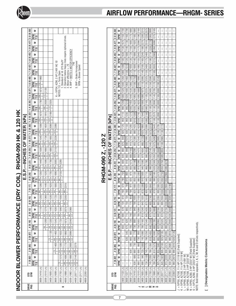
K =
IVP3
4, A
Z90,
2 H
P [1
491
W] 1
ØNO
TES:
T.O
. = T
urns
Ope
n1.
Sta
ndar
d ai
r @ .0
75 lb
s/ft3
2. O
pera
tion
belo
w h
eavy
line
s re
quire
opt
iona
l driv
es.
3. M
otor
effi
cien
cy =
.70
4. B
HP =
WAT
TS x
MOT
OREF
FICI
ENCY
746
5. B
HP =
Bra
ke H
orse
pow
erRP
M =
Blo
wer
Spe
ed
IND
OO
RB
LO
WE
RP
ER
FO
RM
AN
CE
(DR
YC
OIL
)R
HG
M-0
90 H
K &
120
HK
RH
GM
-090
Z,-
120
Z
4000
[188
8 L/
s]78
014
6581
015
7585
016
9088
017
8091
018
8094
020
1097
021
1099
021
8010
2023
0010
5024
0010
7524
9010
7524
4511
0025
7011
3026
9011
4527
8511
7028
5511
8529
2012
1529
8512
6030
9012
7531
65
DRIV
EPK
GST
DCF
M
E.S
.P.—
INC
HE
S O
F W
AT
ER
[kP
a]
4200
[198
2 L/
s]82
517
5085
518
4088
519
2592
020
6094
021
6096
522
6099
523
6510
2524
7010
5025
6010
8026
8010
8026
8511
0027
9511
3028
9011
5030
0011
6530
8011
9031
45—
——
——
——
.1 [0
.02]
—
.2 [0
.05]
4400
[207
7 L/
s]
.3 [0
.07]
845
.4 [0
.10]
1925
.5 [0
.12]
905
.6 [0
.15]
2100
.7 [0
.17]
925
.8 [0
.20]
2195
.9 [0
.22]
950
1.0
[0.2
5]
2320
1.1
[0.2
7]
970
1.2
[0.3
0]
2430
1.3
[0.3
2]
995
1.4
[0.3
5]
2550
1.5
[0.3
7]
1030
1.6
[0.4
0]
2650
1.7
[0.4
2]
1050
1.8
[0.4
5]
2755
1.9
[0.4
7]
1055
2.0
[0.5
0]
2760
1085
2855
RPM
WRP
MW
RPM
WRP
MW
RPM
WRP
MW
RPM
WRP
MW
RPM
WRP
MW
RPM
WRP
MW
RPM
WRP
MW
RPM
WRP
MW
RPM
WRP
MW
RPM
WRP
MW
J K L M N O
2400
[113
3 L/
s]—
——
——
—65
051
069
057
072
061
076
067
079
075
581
580
584
586
087
594
092
011
2595
511
1099
012
0010
0013
2010
4013
5010
8014
9011
0016
3011
3016
7011
5017
00
1100
2600
[122
7 L/
s]—
——
—63
554
567
562
071
566
575
072
078
079
581
086
083
091
086
099
089
010
7093
011
5096
012
3099
513
1010
2014
0010
6014
6011
0015
1011
2016
8011
4017
3011
6017
90
2985
2800
[132
1 L/
s]—
—63
059
566
566
570
572
074
077
577
585
079
591
582
597
585
510
7588
511
6591
512
1095
012
8598
013
7010
0014
5010
4015
3010
8015
9011
2016
5011
3017
2011
5018
0011
7518
80
1130
3000
[141
6 L/
s]63
066
066
073
069
577
573
088
075
594
079
010
0582
510
6585
511
3088
511
9092
012
9095
513
8098
014
2510
1015
0010
3516
2010
6516
9011
0017
5011
1018
0011
4018
8011
6019
2011
8519
80
3115
3200
[151
0 L/
s]66
081
069
586
073
095
075
010
0578
510
8081
511
5085
012
2588
012
8591
013
9095
014
7097
515
4010
1016
2010
3017
4010
6518
2010
9518
8010
9518
9011
2519
8511
5520
4511
7520
9011
9021
60
—
3400
[160
5 L/
s]69
094
072
510
0074
510
9078
011
6081
012
4084
513
2087
513
9091
015
0094
515
9097
016
5099
517
2510
2518
6010
5519
4010
5519
0010
8019
7511
1020
9511
4021
8511
6522
4511
8022
7012
0023
15
—
3600
[169
9 L/
s]73
011
0074
511
7578
012
5081
013
4084
514
3587
515
1090
516
2094
517
1596
017
8099
018
5510
2019
9510
5020
8010
8021
6010
8021
6511
0522
2511
3523
2511
5524
0011
7524
6011
9525
1012
2025
75
—
3800
[179
3 L/
s]74
512
6578
013
5081
014
5584
015
5087
516
3090
517
4094
018
4095
519
0599
020
5010
2521
4510
4522
2510
7523
1510
7522
7011
0023
9011
3024
9511
5025
9011
7026
5011
9027
1012
2027
7012
6528
95
——
——
——
——
——
——
—
4600
[217
1 L/
s]91
522
2593
023
7595
524
9598
026
2010
1027
5010
3028
4010
3529
5010
5529
6010
8030
70—
——
——
——
——
——
——
——
——
——
——
—
4800
[226
5 L/
s]93
025
5596
026
8098
528
1010
1529
4010
3530
4010
3530
4510
5531
80—
——
——
——
——
——
——
——
——
——
——
——
——
—
5000
[236
0 L/
s]96
028
7099
030
1010
2031
35—
——
——
——
——
——
——
——
——
——
——
——
——
——
——
——
——
—
AIRFLOW PERFORMANCE—RHGM- SERIES
7

AIRFLOW PERFORMANCE—RHGM- SERIES
8
COMPONENT AIR RESISTANCERHGM 7.5 TON [26 kW] & 10 TON [35 kW]
NOTE: Add component resistance to duct resistance to determine total E.S.P.
[ ] Designates Metric Conversions
CFM[L/s]
1800[850]
2200[1038]
2600[1227]
3000[1416]
3400[1605]
3800[1793]
4200[1982]
4600[2171]
5000[2360]
Electric Heater 20KW, 30KW .060 [.015] .100 [.025] .140 [.034] .160 [.040] .230 [.057] .320 [.080] .410 [.102] .500 [.124] .600 [.150]
Mixing Box (R/A Damper Open) .006 [.001] .008 [.002] .012 [.003] .024 [.006] .038 [.009] .053 [.013] .068 [.017] .080 [.020] .095 [.024]
Discharge Grille (Set Max. Open) .008 [.002] .011 [.003] .015 [.004] .020 [.005] .025 [.006] .031 [.008] .039 [.010] .046 [.012] .055 [.014]
Inlet Grille .008 [.002] .010 [.002] .014 [.003] .020 [.005] .026 [.006] .032 [.008] .039 [.010] .049 [.012] .058 [.014]
Discharge Plenum .02 [.005] .04 [.010] .05 [.012] .065 [.016] .085 [.021] .100 [.025] .120 [.030] .150 [.037] .180 [.045]

BLOWER PERFORMANCE CURVES—7.5 & 10 TON [26 & 35 kW] (WET COIL)
7.5 & 10 TON [26 & 35 kW]L DRIVE (3Ø only)
7.5 & 10 TON [26 & 35 kW] (RHGM-120 ONLY)J DRIVE (3Ø only)
7.5 & 10 TON [26 & 35 kW]K DRIVE (3Ø only)
7.5 & 10 TON [26 & 35 kW]M DRIVE (3Ø only)
7.5 & 10 TON [26 & 35 kW]N DRIVE (3Ø only)
7.5 & 10 TON [26 & 35 kW]O DRIVE (3Ø only)
[ ] Designates Metric Conversions
AIRFLOW PERFORMANCE—RHGM- SERIES
9
PERFORMANCE DATA—RHGM- SERIES
10
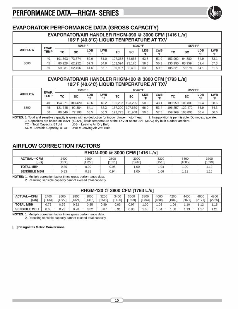
EVAPORATOR PERFORMANCE DATA (GROSS CAPACITY)EVAPORATOR/AIR HANDLER RHGM-090 @ 3000 CFM [1416 L /s]
105°F (40.8°C) LIQUID TEMPERATURE AT TXV
3000
40 101,593 73,674 52.9 51.0 127,358 84,666 63.8 51.9 153,992 94,880 54.9 53.1
45 80,928 62,952 57.3 54.8 103,594 73,170 58.8 56.3 130,995 83,959 59.4 57.3
50 59,031 52,456 61.6 66.7 80,997 82,400 63.0 50.2 105,321 72,678 64.1 61.6
TC SC LDB °F
LWB °F TC SC LDB
°FLWB
°F TC SC LDB°F
LWB°F
AIRFLOW EVAP.TEMP
75/63°F 80/67°F 55/71°F
EVAPORATOR/AIR HANDLER RHGM-120 @ 3800 CFM [1793 L /s]105°F (40.6°C) LIQUID TEMPERATURE AT TXV
50 88,849 77,108 58.5 56.3 122,773 91,908 59.5 57.5 159,969 108,803 60.4 56.6
3800
40 154,071 108,420 49.6 48.2 190,237 123,295 50.5 48.1 189,959 10,8803 60.4 58.6
45 121,745 92,384 54.1 52.3 157,209 107,660 66.0 53.4 196,257 122,470 55.9 54.3
TC SC LDB °F
LWB °F TC SC LDB
°FLWB
°F TC SC LDB °F
LWB °F
AIRFLOW EVAP.TEMP
75/63°F 80/67°F 85/71°F
NOTES: 1. Total and sensible capacity is gross with no deduction for indoor blower motor heat. 2. Interpolation is permissible. Do not extrapolate.3. Capacities are based on 105°F (40.6°C) liquid temperature at the TXV or about 95°F (35°C) dry bulb outdoor ambient.TC = Total Capacity, BTUH LDB = Leaving Air Dry BulbSC = Sensible Capacity, BTUH LWB = Leaving Air Wet Bulb
AIRFLOW CORRECTION FACTORS
NOTES: 1. Multiply correction factor times gross performance data.2. Resulting sensible capacity cannot exceed total capacity.
NOTES: 1. Multiply correction factor times gross performance data.2. Resulting sensible capacity cannot exceed total capacity.
[ ] Designates Metric Conversions
RHGM-090 @ 3000 CFM [1416 L/s]ACTUAL—CFM
[L/s]2400[1133]
2600[1227]
2800[1321]
3000[1416]
3200[1510]
3400[1605]
3600[1699]
TOTAL MBH 0.85 0.90 0.95 1.00 1.04 1.09 1.13
SENSIBLE MBH 0.83 0.88 0.94 1.00 1.06 1.11 1.16
ACTUAL—CFM[L/s]
2400[1133]
2600[1227]
2800[1321]
3000[1416]
3200[1510]
3400[1605]
3600[1699]
3800[1793]
4000[1888]
4200[1982]
4400[2077]
4600[2171]
4800[2265]
RHGM-120 @ 3800 CFM [1793 L/s]
TOTAL MBH 0.76 0.79 0.82 0.85 0.89 0.93 0.97 1.00 1.03 1.06 1.10 1.12 1.15
SENSIBLE MBH 0.68 0.73 0.78 0.82 0.87 0.91 0.96 1.00 1.04 1.08 1.13 1.17 1.21

ELECTRIC HEATER KIT CHARACTERISTICS
NOTE: All kits have two stages of capacity, first stage heating is 50% of total capacity.
ELECTRICAL DATA TABLE
RHGM-090 / RHGM-120 RXHE-DE020CA 208/240 20 43.1/48.9 15.6/20.2
RHGM-090 / RHGM-120 RXHE-DE030CA 208/240 30 60.8/70.2 22.0/29.6
RHGM-090 / RHGM-120 RXHE-DE020DA 480 20 24.7 20.2
RHGM-090 / RHGM-120 RXHE-DE030DA 480 30 35 29.7
AIR HANDLERMODEL
HEATER KITMODEL
HEATER KITVOLTAGE
HEATER KIT[kW]
HEATERKIT
AMPS
HEATINGCAPACITY
[kW]
101.3
68.9
75.1/101
53.2/68.9
HEATINGCAPACITY
MBH
50
37
89/100
67/73
MINIMUMCIRCUIT
AMPACITY
50
40
90/100
70/80
MAX. FUSEOR HACRBREAKER
SIZE
NOTE: N.E.C., C.E.C. and local codes take precedence over suggested wire and fuse sizes.
[ ] Designates Metric Conversions
AIR HANDLERMOTOR
RATINGPLATEAMPS
MOTORLRA
MINIMUMCIRCUIT
AMPACITY
RECOMMENDED MINIMUM CuWIRE SIZE
(3% VOLTAGE 75°C DROP)MAX. RUN IN FEET
MAX.FUSES
BREAKERSHP [W] VOLTS PHASE
1 [746]1 [746]1 [746]
208-230460
115-230
3Ø3Ø1Ø
4.0/3.61.816/8
23.9/21.610.8
96/48
1515
20/15
#14/240#14/400
#12/120 #14/180
1515
20/15
11/2 [1119]11/2 [1119]
208-230 460
3Ø3Ø
5.7/5.22.6
34.5/31.215.6
1515
#14/230#14/300
1515
2 [1491]2 [1491]2 [1491]
208-230 460
115-230
3Ø3Ø1Ø
7.5/6.83.4
24/12
45.1/40.820.4
144/72
1515
30/15
#14/165#14/275
#10/140 #14/120
1515
30/15
3 [2237]3 [2237]
208-230 460
3Ø3Ø
10.6/9.64.8
64.1/5826.8
1515
#14/135#14/230
1515
PERFORMANCE DATA/ELECTRIC HEATER KITS—RHGM- SERIES
11

OPTIONALHEATER KIT
ELECTRIC HEATER KITS—RHGM- SERIES
12

AIR HANDLER ACCESSORIES RXHM MIXING BOX
RXHE ELECTRIC HEATER KIT
ACCESSORYDESCRIPTION
MODELNUMBER
SIZESUSED ON
NET WEIGHT(LBS) [kg]
Hot Water Coil RXHC-C74W 090, 120 200 [91]
Steam Coil RXHC-C74S 090, 120 200 [91]
Filter Frame Kit RXHF-B74A 090, 120 90 [41]
Inlet Grille Kit RXHG-C74A 090, 120 9 [4]
DischargeGrille Kit RXHG-C74B 090, 120 15 [7]
DischargePlenum Kit RXHL-C74B 090, 120 38 [17]
Mixing Box RXHM-BC74H 090, 120 120 [54]
AuxiliaryHeater Kit
RXHE-DE020*A 090, 120 75 [34]
RXHE-DE030*A 090, 120 75 [34]
NOTE: *Designates “C”, “D” or “Y” Voltage
[ ] Designates Metric Conversions
HOT WATER OR STEAM COILS
(090, 120) RXHC-C74WRXHC-C74S
(090, 120) RXHC-C74WRXHC-C74
ACCESSORIES—RHGM- SERIES
13

PHYSICAL SPECIFICATIONS
STEAM COIL COIL DIMENSIONS—INCHES [mm]
GROSS COIL PERFORMANCE
HOT WATER COIL DIMENSIONS—INCHES [mm]
1. Entering air temperature @ 60°F2. Entering steam @ 5 PSIG3. Entering water @ 200°F
4. Face velocity = CFMFace Area
STEAM COIL
HOT WATER COIL
600
VELOCITYFPM
80010 [35.17] 285,000 240,000 4,000 [1888]
NOMINALTONS [kW]
NOMINAL BTUH NOMINALCFM [ L/s]
71/2 [26.38] 242,500 185,000 3,000 [1416]
STEAM WATER
12
CIRCUITS& TUBES
HIGH
NOMINALTONS [kW]
FINNEDHEIGHT–IN. [mm]
FINNEDLENGTH–IN. [mm]
FACEAREA
FT2 [m2]71/2 [26.38]-10 [35.17] 18 [457] 40 [1016] 5.0 [.46]
CMODEL NOMINAL TONS [kW] A B D E F G H J K L M53/8
[137]RXHC-C74 71/2 [26.38]-10 [35.17]
91/16
[230]213/8[543]
33/16
[81]15
[381]24
[610]11/2[38]
11/4[32]
511/2[1308]
475/8[1210]
213/16
[71]31/4[83]
CMODEL NOMINAL TONS [kW] A B D E F G H J K L M53/8
[137]RXHC-C74W 71/2 [26.38]-10 [35.17]
91/16
[230]213/8[543]
33/16
[81]15
[381]24
[610]11/4[32]
11/4[32]
511/2[1308]
475/8[1210]
213/16
[71]3
[76]
[ ] Designates Metric Conversions
AIR HANDLER ACCESSORIES (con’t)
ACCESSORIES—RHGM- SERIES
14

AIR HANDLER ACCESSORIES (con’t)HOT WATER COILS
TABLE IVCurve 2 ratings are based on 200°F entering water and20°F temperature drop. For other conditions use the follow-ing correction factors:
BASIC FORMULA:
Air Temperature Rise, °F = BTUH1.08 x CFM
Water Temperature Drop, °F = BTUH500 x GPM
HOT WATER COIL SELECTION:Specified:Entering Air Temp. @ 40°F5000 CFM @ 6000 Ft. Elevation220°F Entering Water Temp. @ 36 GPM
Select 10 Ton Nominal Coil:Face Area = 5 Ft2
Circuits = 12
Determine Coil Performance:From Table I, Altitude and Temperature Correction Factor = 1.19 Std. CFM = 5000/1.19 = 4202Face Velocity = 4202/5 = 840 FPMFrom Curve 2, BTUH/Ft2 = 57,500Coil Capacity = 5 x 58,000 = 287,500 BTUHWater Temp. Drop = 290,000/(500 x 36) = 16.1°FFrom Table IV, Water Temp. Factor = 1.14From Table IV, Water Temp. Drop Factor = 1.012Total Capacity = 287,500 x 1.14 x 1.015 = 334,570 BTUHFrom Curve 3, Water Pressure Drop 36 GPM/12 Circuits = 3 GPM/Circuit = 1.6 FT. HD.From Table II, Air Side Pressure Drop = .38" H2O
STEAM COIL
CURVE 2HOT WATER COIL
CURVE 3HOT WATER COIL WATER
PRESSURE DROP
ENTERINGWATER °F FACTOR
WATERTEMPERATURE
DROP °FFACTOR
220210200190180
1.141.071.00.98.93
1015202530
1.0301.0151.000.985.970
ACCESSORIES—RHGM- SERIES
15

AIR HANDLER ACCESSORIES (con’t)STEAM COILS AIRFLOW
TABLE IALTITUDE AND TEMPERATURE CORRECTION FACTOR TABLE
Standard Air = Specified CFMCorrection Factor
EXAMPLE: Determine Equivalent “Standard Air” for use in System Performance Calculations:
.92 .94 .96 .98
AIRTEMP.
(F)
ALTITUDE IN FEET ABOVE SEA LEVEL
0 .87 .89 .91 .99 1.01 1.03 1.05 1.09 1.13 1.17 1.22 1.26
1500 2000 2500 30000 500 1000 3500 4000 4500 5000 6000 7000 8000 9000 10,000
1.00 1.02 1.04 1.0640 .94 .96 .98 1.08 1.10 1.12 1.14 1.19 1.23 1.28 1.32 1.36
1.06 1.08 1.10 1.1270 1.00 1.02 1.04 1.14 1.19 1.18 1.20 1.25 1.30 1.35 1.40 1.45
1.12 1.14 1.16 1.19100 1.06 1.08 1.10 1.21 1.23 1.25 1.28 1.33 1.38 1.43 1.48 1.54
1.16 1.18 1.20 1.23120 1.09 1.12 1.14 1.25 1.28 1.30 1.32 1.38 1.43 1.48 1.53 1.58
TABLE IIAIR FRICTION LOSS
ACCESSORIES—RHGM- SERIES
16
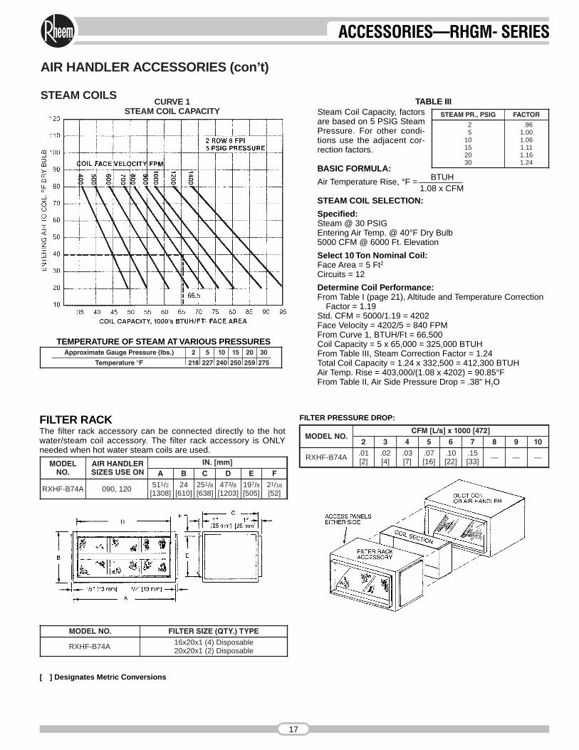
AIR HANDLER ACCESSORIES (con’t)
STEAM COILSCURVE 1
STEAM COIL CAPACITY
TEMPERATURE OF STEAM AT VARIOUS PRESSURES
TABLE IIISteam Coil Capacity, factorsare based on 5 PSIG SteamPressure. For other condi-tions use the adjacent cor-rection factors.
BASIC FORMULA:
Air Temperature Rise, °F = BTUH1.08 x CFM
STEAM COIL SELECTION:
Specified:Steam @ 30 PSIGEntering Air Temp. @ 40°F Dry Bulb5000 CFM @ 6000 Ft. Elevation
Select 10 Ton Nominal Coil:Face Area = 5 Ft2Circuits = 12
Determine Coil Performance:From Table I (page 21), Altitude and Temperature Correction
Factor = 1.19Std. CFM = 5000/1.19 = 4202Face Velocity = 4202/5 = 840 FPMFrom Curve 1, BTUH/Ft = 66,500Coil Capacity = 5 x 65,000 = 325,000 BTUHFrom Table III, Steam Correction Factor = 1.24Total Coil Capacity = 1.24 x 332,500 = 412,300 BTUHAir Temp. Rise = 403,000/(1.08 x 4202) = 90.85°FFrom Table II, Air Side Pressure Drop = .38" H2O
STEAM PR., PSIG FACTOR
25
10152030
.961.001.061.111.161.24
Approximate Gauge Pressure (lbs.) 2 5 10 15
Temperature °F 218 227 240 250 259
20
275
30
MODEL NO. FILTER SIZE (QTY.) TYPE
RXHF-B74A 16x20x1 (4) Disposable20x20x1 (2) Disposable
FILTER RACKThe filter rack accessory can be connected directly to the hotwater/steam coil accessory. The filter rack accessory is ONLYneeded when hot water steam coils are used.
FILTER PRESSURE DROP:
MODELNO.
AIR HANDLERSIZES USE ON
IN. [mm]
RXHF-B74A 090, 120 511/2[1308]
24[610]
251/8[638]
473/8[1203]
197/8[505]
21/16
[52]
A B C D E F
MODEL NO.CFM [L/s] x 1000 [472]
2 3 4 5 6 7 8 9 10
RXHF-B74A .01[2]
.02[4]
.03[7]
.07[16]
.10[22]
.15[33] — — —
[ ] Designates Metric Conversions
ACCESSORIES—RHGM- SERIES
17

UNIT WITH ACCESSORIES7.5 THROUGH 10 NOMINAL TONS [26 THROUGH 35 kW]
AIR HANDLER ACCESSORIES (con’t)
DOUBLE DEFLECTION DISCHARGE GRILLE
[ ] Designates Metric Conversions
MODEL NO. AIR HANDLERSIZES USED ON
NOMINALCFM [L/s] FT. [m] OF THROW
RXHG-C74B
090 3000[1416]
0° DEFLECTION - 43' [13.1]22° DEFLECTION - 37' [11.3]45° DEFLECTION - 22' [6.7]
120 4000[1888]
0° DEFLECTION - 53' [16.2]22° DEFLECTION - 46' [14]45° DEFLECTION - 27' [8.2]
TYPICAL APPLICATION7.5 & 10 NOMINAL TONS[26 & 35 kW] FOUR HEAVY GAUGE ANGLES ARE FURNISHED (SHIPPED LOOSE) FOR
SUSPENDING UNITS FROM ALL FOUR CORNERS, MINIMUM OF 1/2" [13]SUPPORT RODS ARE RECOMMENDED. IF ALL-THREAD IS USED, IT ISALSO RECOMMENDED THAT TWO NUTS AND TWO LOCKWASHERS BETIGHTENED SECURELY AGAINST THE SUSPENSION ANGLES.
WHEN HOT WATER OR STEAM COIL, MIXING BOX OR DISCHARGE AIRPLENUM ACCESSORIES ARE REQUIRED, UNITS CANNOT BE SUS-PENDED AS ILLUSTRATED, AN ALTERNATE SUSPENSION METHOD SUCHAS ANGLES OR CHANNELS (FIELD SUPPLIED) SHOULD BE LOCATEDUNDER UNIT. (SHOWN BELOW)
OPTIONAL ELECTRICAL HEATER KIT SHOWN INSTALLED IN HORIZONTALPOSITION AND CONNECTED DIRECTLY TO THE AIR HANDLER. THEHEATER KIT MAY ALSO BE INSTALLED WITH THE AIR HANDLER SET IN THEVERTICAL POSITION. IN EITHER POSITION THE HEATER KIT CONTROLCOMPARTMENT MUST BE ON THE LEFT SIDE FACING THE AIR DISCHARGEOPENING.
AUXILIARY HEATER KITMODEL NO. AIR HANDLERSSIZES USED ON
IN. [mm]A B
RXHE-DE����A 090, 120 20 [508] 20 [508]
THE BOTTOM OF THE AIR HANDLER SHOULD BE SLOPED IN TWO PLANESTHAT PITCH THE CONDENSATE TO THE DRAIN CONNECTION. THE DRAINPAN SHOULD NOT LEAVE PUDDLES LARGER THAN 2 INCHES IN DIAMETERAND 1/8 INCH DEEP FOR MORE THAN 3 MINUTES.
ACCESSORIES—RHGM- SERIES
18

MIXING BOX ACCESSORY—OPERATING SEQUENCE
CAUTION: IT IS NOT RECOMMENDED THAT HOT WATEROR STEAM COILS BE USED WITH THE MIXING BOXACCESSORY WITHOUT A SUITABLE FREEZE-STAT TOPREVENT THE POSSIBILITY OF FREEZING THE COIL.
[ ] Designates Metric Conversions
MIXING BOX
COOLING SEASON—Thermostat set at “Cool” and “FanAuto,” outside air damper goes to “minimum fresh air” positionwhen cooking thermostat closes, energizing mechanical cool-ing. When cooling thermostat is satisfied, mechanical coolingis de-energized, and outside air damper closes.
INTERMEDIATE SEASON—Same as for cooling season,except that cooling thermostat closes, starting indoor blowermotor, the enthalpy control, mounted on outside air, deter-mines if “free” cooling or mechanical cooling should be uti-lized. If outside air conditions are suitable for cooling, themechanical cooling remains off and the mixed air controllermodulates the damper motor to assume the proper damperposition to maintain mixed air setting. If outside conditions
are not suitable for cooling, then the dampers go to “minimumfresh air” position and mechanical cooling is energized.
HEATING SEASON—Damper always stays at “minimum freshair” position while fan motor is operating. Outside air dampercloses when blower motor is off. “Minimum fresh air” positionmust not allow mixed air temperatures to air handler below50°F. [10°C] during heating seasons.
MODEL NO. AIR HANDLERSIZES USED ON
FLANGED DUCT OPENINGS
27 [686]
“X”LENGTH IN. [mm] WIDTH IN. [mm]RXHM-BC74H 090, 120 42 [1067] 167/8 [454]
IN. [mm]
ACCESSORIES—RHGM- SERIES
19

PIPING—RHGM- SERIES
20
INDOOR COIL BELOWOUTDOOR UNIT
TYPICAL PIPING RECOMMENDATIONSINDOOR COIL ABOVEOUTDOOR UNIT
The 7.5 [26 kW] and 10 [35 kW] Air Handlers are designed astwo (2) circuit, full face equal distribution coils. As shipped fromthe factory, the suction and liquid lines are dual circuits. Copperfittings are supplied in the unit to field manifold the suction andliquid lines for single circuit.
NOTE: The expansion valve bulbs must be secured to the cor-responding suction lines. The circuits are markedaccordingly. See illustration under Typical Piping rec-ommendations for additional information.
REFRIGERANT PIPING (See Tables at Right)
The following will be of help in accomplishing a successful installation.
1. Size liquid line for no more than 50 PSIG [345 kPa] pressuredrop.
2. Size suction lines for no more than 2°F [1.1°C] loss which cor-responds to approximately 5 PSIG [34 kPa] pressure drop.
3. When indoor unit is installed below outdoor unit, do notexceed the recommended vapor line O.D. This will insureadequate velocities for proper oil return.
4. Install strainer-drier and sight glass in liquid line.
5. Pitch all horizontal suction lines downward in the direction offlow for cooling only applications.
6. Locate the outdoor unit and indoor unit as close together aspossible to minimize piping runs.
7. A liquid line solenoid installed just ahead of the expansionvalue is recommended for cooling only applications. Be surecondensing unit is suitable for pump down.
8. Piping runs between condenser and evaporator not toexceed 150' [46 m] linear length (90' [27 m] linear length forheat pumps).
NOTE: Refer to suction and liquid line pressure drop chartsfound in condensing unit and remote heat pumpliterature.
[ ] Designates Metric Conversions
CONDENSATE DRAIN PIPING• Consult local codes or ordinances for specific requirements
regarding condensate drain.• Condensate drain is open to atmosphere and must be trapped.
Trap must be at least 3 inches [76 mm] deep and made of flexiblematerial or fabricated to prevent freeze-up.
• Pitch the drain line at least 1/4 inch [6 mm] per foot away from thedrain pan.
• Do not reduce the drain line size from the connection size pro-vided on the unit.
• Do not connect the drain line to a closed sewer line.
*For cooling only, refer to remote heat pump literature for pipingrecommendations.
PIPING SIZES 090 & 120
101-150 [31-46] 1/2 [13] 5/8 [16] 13/8 [35]
LINEARLENGTH, FT. [m]
LIQUIDLINE O.D., IN. [mm]
15/8 [41]
SUCTIONLINE O.D., IN. [mm]
090 120 090 120
0-50 [0-15] 1/2 [13] 5/8 [16] 11/8 [29] 13/8 [35]
51-100* [16-30] 1/2 [13] 5/8 [16] 13/8 [35] 15/8 [41]
EQUIVALENT LENGTH, FT. [m] OF STRAIGHT TYPE “L” TUBINGFOR NON-FERROUS VALVES AND FITTINGS (BRAZED)
TUBE SIZEINCHES [mm]
O.D.
SOLE-NOID
VALVE
ANGLEVALVE
SHORTRADIUS
ELL
LONGRADIUS
ELL
TEELINE
FLOW
TEEBRANCH
FLOW1/2 [13] 70 [21.3] 8.3 [2.5] 1.6 [0.5] 1.0 [0.3] 1.0 [0.3] 3.1 [0.9]5/8 [16] 72 [21.9] 10.4 [3.2] 1.9 [0.8] 1.2 [0.4] 1.2 [0.4] 3.6 [1.1]3/4 [19] 75 [22.9] 12.5 [3.8] 2.1 [0.7] 1.4 [0.4] 1.4 [0.4] 4.2 [1.3]7/8 [22] 78 [23.8] 14.8 [4.4] 2.4 [0.7] 1.6 [0.5] 1.6 [0.5] 4.8 [1.5]
11/8 [29] 18.8 [5.7] 3.0 [0.9] 2.0 [0.6] 2.0 [0.6] 6.0 [1.8]
13/8 [35] 22.9 [7.0] 3.6 [1.1] 2.4 [0.7] 2.4 [0.7] 7.2 [2.2]
15/8 [41] 27.1 [8.3] 4.2 [1.3] 2.8 [0.8] 2.8 [0.8] 8.4 [2.6]
21/8 [54] 35.4 [10.8] 5.3 [1.6] 3.5 [1.1] 3.5 [1.1] 10.7 [3.3]

GUIDE SPECIFICATIONS—RHGM- SERIES
21
OPERATING SEQUENCENOTE: Please refer to specification sheets covering RAWL- condensing units for operating sequence.
GUIDE SPECIFICATIONS
Furnish and install as shown on the drawing Rheem Model––––––––––––– draw through air handler suitable for both hori-zontal and vertical applications. The entire assembly shall be ULand cUL listed with the cooling (and heat pump heating) capacityA.R.I. Certified.
DRIVE PACKAGE—A complete drive package shall be factoryor field installed. Package shall consist of a 3450 RPM dual volt-age, single phase open drip proof motor or a 3 phase 1750 RPMopen drip proof internally protected motor, not requiring an exter-nal starter. Variable pitch motor sheave, fixed pitch fan sheave,and belt.
COILS—Coils shall be fabricated of 3/8" [10 mm] O.D. seamlesscopper tubing expanded into aluminum fins. All coils shall besubmitted to an air pressure test of up to 550 PSIG [2068 kPa]under water after fabrication and dehydrated prior to assembly inunit. Units shall be shipped with a nitrogen holding charge. Airflow shall be draw through design providing uniform air distri-bution across the coil surface.
BLOWER, BEARINGS AND SHAFT—Fans shall be a doublewidth, double inlet, forward curve, centrifugal type, statically anddynamically balanced, and constructed of galvanized steel. Theyshall be mounted on 3/4" [19 mm] = 7.5 ton [26 kW] & 10 ton [35kW], diameter solid shafts made of high carbon steel, centerlessground and polished, supported by resilient mounted sealedbearings.
DRAIN PAN—The drain pan shall be manufactured of zinccoated steel. The pan shall have internally threaded pipe sizedrain connections and shall be designed to accept condensate ineither horizontal or vertical type applications on either side ofunit.
FILTERS—Filter mounting hardware shall be designed to acceptup to 2" [51 mm] filters for field replacement. One inch [25 mm]throw away filters shall be furnished with the unit.
CABINET—Cabinets shall be manufactured of galvanized steelsubjected to multi-stage cleaning and finished with powder coatpaint. Units shall have removable service access panels on eachside and top.
INSULATION—Cabinets shall be insulated with 1/2" [13 mm] by11/2 pound [.68 kg] density fiberglass insulation coated with neo-prene and bonded to the cabinet surface with a U.L. approvedadhesive. Insulation shall have fire retarding characteristics inaccordance with smoke developed rating not to exceed 50 andflame spread rating of 25 per Underwriters Laboratories testingprocedures.
FACTORY TESTING—In addition to the pre-assembly testingmentioned above, each coil shall be leak tested after assemblyinto the unit. While under pressure, the coil shall be leak testedusing an Electronic Leak Detector.
ELECTRIC HEATERS—UL and cUL listed electric heater kitsshall be available in a wide range of capacities. All kits shall offertwo stages of capacity, blower motor controller and single pointconnection. Heater kits shall be available for installation directly onthe supply fan discharge for either horizontal or vertical application.
MIXING BOX—Mixing box accessory shall be available for mix-ing return air with outside air before entering the air handler. Theaccessory shall include both return and outside air dampers andeconomizer controls factory mounted. Economizer controls shallinclude enthalpy and mixed air sensors and damper motors.Mixing box accessory shall be available for installation to thereturn air section of the air handler for either horizontal or verticalapplications.
DISCHARGE PLENUM AND GRILLE—Shall be available forvertical application. Discharge grille shall provide manuallyadjustable double deflection discharge vanes.
RETURN AIR GRILLES—Shall be provided for vertical returnapplications.
HOT WATER OR STEAM COILS—Shall be available for fieldinstallation. All coils shall be tested to 300 psi. Coils shall beavailable for either horizontal or vertical air handler applications.
[ ] Designates Metric Conversions

NOTES
22

NOTES
23
GENERAL TERMS OF LIMITED WARRANTY*Rheem will furnish a replacement for any part of this productwhich fails in normal use and services within the applicableperiods stated below, in accordance with the terms of the limited warranty.
Any Part ..........................................................One (1) Year
*For Complete Details of the Limited Warranty, IncludingApplicable Terms and Conditions, See Your Local Installer orContact the Manufacturer for a Copy.
Before proceeding with installation, referto installation instructions packagedwith each model, as well as complyingwith all Federal, State, Provincial, andLocal codes, regulations, and practices.
Rheem Heating,Cooling andWater Heating
P.O. Box 17010, Fort Smith, AR 72917
“In keeping with its policy of continuous progress and product improvement, Rheem reserves the right to make changes without notice.”
PRINTED IN U.S.A. 8-09 DC FORM NO. H11-532Supersedes Form No. H11-532 Rev. 2