commander 950 pro - holley
TRANSCRIPT
1
COMMANDER 950 PRO TOTAL ENGINE MANAGEMENT SYSTEM
ELECTRONICS AND FUEL INJECTION MANUAL
199R-10149-7
NOTE: These instructions must be read and fully understood before beginning installation. If this manual is not fully understood, installation should not be attempted. Failure to follow these instructions may result in subsequent system failure.
Copyright © 2004 by Holley Performance Products, Inc. Any unauthorized reproduction of this manual without the express written
permission of Holley Performance Products, Inc. is strictly prohibited.

2 2
INTRODUCTION ..........................................................................................................................................................5
1.0 TERMS & DEFINITIONS OF FUEL INJECTION MANAGEMENT SYSTEMS ...................................................6
1.1 FUEL MANAGEMENT SYSTEM .................................................................................................................................6 1.2 THROTTLE BODY INJECTION (TBI)..........................................................................................................................6 1.3 MULTI-POINT FUEL INJECTION (MPFI)....................................................................................................................7 1.4 ELECTRONIC CONTROL UNIT (ECU).......................................................................................................................7 1.5 THROTTLE BODY ASSEMBLY (TBA)........................................................................................................................7 1.6 FUEL INJECTORS ...................................................................................................................................................8
1.6.1 Bottom-Fed Fuel Injector ..............................................................................................................................8 1.6.2 Top-Fed Fuel Injector ...................................................................................................................................8 1.6.3 High-Impedance Injectors.............................................................................................................................8 1.6.4 Low-Impedance Injectors .............................................................................................................................9
1.7 MANIFOLD ABSOLUTE PRESSURE SENSOR (MAP) ..................................................................................................9 1.8 THROTTLE POSITION SENSOR (TPS) .....................................................................................................................9 1.9 IDLE AIR CONTROL VALVE (IAC) ............................................................................................................................9 1.10 MANIFOLD AIR TEMPERATURE SENSOR..............................................................................................................10 1.11 COOLANT TEMPERATURE SENSOR .....................................................................................................................10 1.12 OXYGEN SENSOR..............................................................................................................................................10 1.13 ELECTRIC IN-LINE FUEL PUMP............................................................................................................................10 1.14 ELECTRIC IN-TANK FUEL PUMP ..........................................................................................................................11 1.15 FUEL PUMP INLET FILTER ..................................................................................................................................11 1.16 MAIN FUEL FILTER ............................................................................................................................................11 1.17 FUEL PRESSURE REGULATOR............................................................................................................................11 1.18 FUEL RAILS.......................................................................................................................................................12 1.19 FUEL INJECTION CONTROL METHODS.................................................................................................................12
1.19A Speed Density EFI Systems .....................................................................................................................12 1.19B Alpha-N EFI Systems................................................................................................................................12
1.20 CLOSED LOOP...................................................................................................................................................12 1.21 OPEN LOOP ......................................................................................................................................................13
2.0 HOW DOES FUEL INJECTION WORK?.............................................................................................................13
2.1 SPEED DENSITY ..................................................................................................................................................15 2.2 ALPHA-N.............................................................................................................................................................16
3.0 SKILL LEVEL REQUIRED...................................................................................................................................17
4.0 TOOLS REQUIRED FOR INSTALLATION..........................................................................................................17
5.0 ELECTRICAL CONNECTIONS ...........................................................................................................................17
5.1 STEP-BY-STEP WIRING HARNESS INSTALLATION ..................................................................................................18 5.2 NON-TERMINATED WIRE CONNECTION.................................................................................................................18 5.3 PLUG-IN CONNECTIONS .......................................................................................................................................19 5.4 IGNITION WIRING.................................................................................................................................................20
6.0 SOFTWARE INSTALLATION, SOFTWARE OPERATIONAL DESCRIPTION, COMPUTER OPERATION, &
FUEL MAP DOWNLOADING .....................................................................................................................................21
6.1 SOFTWARE INSTALLATION....................................................................................................................................21 6.1.1 Windows 95, 98, NT, ME, 2000..................................................................................................................21 6.1.2 Windows 3.1 .................................................................................................Error! Bookmark not defined.
6.2 BASIC COMPUTER OPERATION.............................................................................................................................21 6.3 SOFTWARE OPERATION AND NAVIGATION ............................................................................................................21 6.4 BASE MAPS ........................................................................................................................................................23 6.5 ADVANCED AND BEGINNING USERS......................................................................................................................23
7.0 STEP-BY-STEP INITIAL STARTUP INSTRUCTIONS ........................................................................................23
8.0 STEP-BY-STEP BASIC START-UP TUNING......................................................................................................28
8.1 STARTUP / ENGINE WON’T START ........................................................................................................................28

3
9.0 FUEL MAP TUNING.............................................................................................................................................33
9.1A FUEL MAP TUNING WITH NARROW-BAND OXYGEN SENSOR................................................................................33 9.1B FUEL MAP TUNING WITH WIDE-BAND OXYGEN SENSOR .....................................................................................38 9.2A FUEL MAP TUNING (LOW SPEED) ......................................................................................................................41 9.2B FUEL MAP TUNING (HIGH LOAD & RPM)............................................................................................................43
10.0 REQUIRED ADDITIONAL EFI TUNING ............................................................................................................45
11.0 ALPHA-N TUNING.............................................................................................................................................59
12.0 DATA LOGGER .................................................................................................................................................62
12.1 STARTING THE PC DATALOGGER .......................................................................................................................62 12.2 STARTING THE INTERNAL DATALOGGER..............................................................................................................63
12.3 Datalogger Speed........................................................................................................................................63 12.4 Dataset Size ................................................................................................................................................63
12.5 DOWNLOADING LOGGED DATA TO THE PC. ........................................................................................................64 12.6 VIEWING DATA ..................................................................................................................................................64
13.0 INPUT/OUTPUTS ..............................................................................................................................................65
13.1 INPUT/OUTPUT ..................................................................................................................................................65 13.1.1 Input 1 (12V activation – B8) .....................................................................................................................66 13.1.2 Input 2 (GND activation – B10).................................................................................................................66 13.1.3 Output 1 (D9)............................................................................................................................................66 13.1.4 Output 2 (C1)............................................................................................................................................66
13.2 DATALOGGER....................................................................................................................................................66 13.3 ABOUT ..............................................................................................................................................................66 13.4 NOTES..............................................................................................................................................................66 13.5 VERSION...........................................................................................................................................................66 13.6 ADVANCED USER ..............................................................................................................................................66
APPENDIX 1 COMPLETE SOFTWARE OVERVIEW................................................................................................66
COMMANDS............................................................................................................................................................67 File ........................................................................................................................................................................67 Retrieve ECU Data ...............................................................................................................................................67 Send ECU Data ....................................................................................................................................................67 Force Default Values ............................................................................................................................................67 Open Data from Disk ............................................................................................................................................67 Open only Fuel Data from Disk ............................................................................................................................67 Open only Spark Data from Disk ..........................................................................................................................67 Save Data to Disk.................................................................................................................................................67 Save Fuel Map as Excel File ................................................................................................................................67 Save Spark Map as Excel File..............................................................................................................................67 Print All .................................................................................................................................................................67 Password..............................................................................................................................................................68 Exit........................................................................................................................................................................68 Comm ...................................................................................................................................................................68
FUEL........................................................................................................................................................................68 Main Fuel Map ......................................................................................................................................................68 Data Monitor .........................................................................................................................................................69 Fuel Graph............................................................................................................................................................70 Startup Enrichment ...............................................................................................................................................70 Acceleration Enrichment.......................................................................................................................................71 Modifiers ...............................................................................................................................................................72
SPARK.....................................................................................................................................................................73 Main Spark Map....................................................................................................................................................73 Main Spark Graph.................................................................................................................................................73 Idle Spark Control .................................................................................................................................................74 Knock Control .......................................................................................................................................................74
DATALOGGER ............................................................................................................................................................75 HARDWARE SETTINGS (HDWR SETTINGS)...................................................................................................................75
4 4
Engine Parameters ...............................................................................................................................................75 Idle Air Control ......................................................................................................................................................77 PID Definitions (for Idle Air Control)......................................................................................................................78 Closed Loop Parameters......................................................................................................................................78 Input/Output ..........................................................................................................................................................81
ABOUT.......................................................................................................................................................................82 Notes ....................................................................................................................................................................82 Version..................................................................................................................................................................82
APPENDIX 2 APPLICATION SPECIFIC TUNING .....................................................................................................83
SPECIFIC INFORMATION FOR RACE APPLICATIONS .......................................................................................................83 TBI SPECIFIC TUNING INFORMATION...........................................................................................................................84 5.0L FORD SPECIFIC TUNING INFORMATION ................................................................................................................85
APPENDIX 3 TUNING TROUBLESHOOTING..........................................................................................................85
APPENDIX 4 GENERAL TROUBLESHOOTING ......................................................................................................89
APPENDIX 5 TESTING AND TROUBLESHOOTING ELECTRICAL COMPONENTS .............................................90
TESTING RELAYS .......................................................................................................................................................90 TESTING THE MANIFOLD ABSOLUTE PRESSURE (MAP) SENSOR (1 BAR)......................................................................90 TESTING THROTTLE POSITION SENSOR (TPS) ............................................................................................................90 TESTING IDLE AIR CONTROL (IAC) MOTOR .................................................................................................................91 TESTING COOLANT TEMPERATURE SENSOR................................................................................................................91 TESTING AIR CHARGE TEMPERATURE SENSOR ...........................................................................................................91 TESTING THE OXYGEN SENSOR (NARROW-BAND ONLY) ..............................................................................................91
APPENDIX 6 OXYGEN SENSOR EFFECT ON PERFORMANCE............................................................................92
APPENDIX 7 DESCRIPTION OF FUEL INJECTION SYSTEMS ..............................................................................93
COMBUSTION PRINCIPLES AND AIR / FUEL RATIOS ......................................................................................................93 EMISSIONS AND PERFORMANCE..................................................................................................................................95 ENGINE MANAGEMENT SYSTEMS ................................................................................................................................95
Air Management ...................................................................................................................................................95 Fuel Management.................................................................................................................................................96 Ignition Timing Management ................................................................................................................................97
APPENDIX 8 THE ENGINE APPLICATION AND THE SELECTION OF YOUR FUEL MANAGEMENT SYSTEM
COMPONENTS. .........................................................................................................................................................97
INJECTOR FUEL FLOW ................................................................................................................................................97 FUEL PRESSURE ........................................................................................................................................................98 BIGGER IS BETTER (TRUE OR FALSE) ..........................................................................................................................98
APPENDIX 9 FUEL PUMPS ......................................................................................................................................99
APPENDIX 10 WIRING DIAGRAMS........................................................................................................................100
HOLLEY PERFORMANCE PRODUCTS LIMITED WARRANTY .............................................................................................114

5
INTRODUCTION
Thank you for your purchase of the Holley Commander 950 PRO Fuel Injection System. This tuning manual is designed to take all of the guesswork out of tuning your Commander 950 PRO. Holley is dedicated to providing products for our customers that not only outperform your expectations, but also are easy to install and tune.
NOTE: We highly recommend that you carefully read through all the manuals included with your system before installing and tuning your Commander 950 PRO Fuel Injection System. This will eliminate many problem areas and wasted time. This manual covers only the wiring and tuning aspects of the Commander 950 PRO. The hardware
installation manual (if included) will cover all aspects of the actual installation of the mechanical components (manifold, throttle bodies, etc.).
The Commander 950 PRO systems are the most powerful fuel injection systems available today and are constructed from the highest quality components that have guided many racers to the winner's circle. Holley’s race-winning heritage and technology is taken to the next step with our Commander 950 PRO fuel injection systems. These systems are perfect for both street and full-blown race applications, yet are user friendly.
This controller will allow you to tune fuel delivery, spark timing, boost compensation, fuel pump control, cooling fan, idle quality, and much more. As sophisticated as this system is, this tuning manual will walk you through each step, giving you maximum power, driveability, and reliability out of your engine.
Chapter 1 of this manual consists of the terms and definitions of fuel injection management systems. This is a glossary of components that you will encounter during the installation and tuning of your Commander 950 PRO fuel injection system.
Chapter 2 of this manual will focus on the fundamentals and theory behind electronic fuel injection (EFI). This is where you will learn about how and why fuel injection works.
Chapter 3 will focus on the skills required to install your Commander 950 PRO system. This includes items such as: basic computer knowledge, limitations of the system, and general automotive knowledge.
Chapter 4 will focus on the tools required to install your Commander 950 PRO system
Chapter 5 gives comprehensive instruction on the wiring installation of your Commander 950 PRO system. This is a very comprehensive section and includes step-by-step instructions that are easy to follow in very simple terms.
Chapter 6 covers the software installation, software operational description, computer operation, and fuel map downloading.
Chapter 7 provides step-by-step instruction to get you through initial fire up.
Chapter 8 goes through the basic tuning of your Commander 950 PRO.
Chapter 9 will cover the fuel map tuning with wide-band and narrow-band oxygen sensors. It will also covers the fine points of tuning required to realize optimal performance. This advanced tuning section will allow you to squeeze every last bit of power and driveability out of your vehicle.
Chapter 10 covers the required additional tuning.
Chapter 11 covers some basic fundamentals for Alpha N systems.
Chapter 12 covers the Datalogger functions. Chapter 13 covers the Input and Output functions.
Appendix 1 covers software overview, including: hardware settings, idle air control, PID definitions, and O2.
Appendix 2 covers application specific tuning. It will include sections on Race Application, TBI applications, and 5.0L Ford applications.
Appendix 3 covers tuning troubleshooting.
Appendix 4 is our general troubleshooting guide. This section will answer many of the most common stumbling areas in fuel injection tuning. If you are having a problem, start by looking through this section first.
Appendix 5 covers the testing and troubleshooting of electrical components, including the testing of : Relays, MAP Sensor, TPS, IAC, Coolant Temperature Sensor, Air Charge Temperature Sensor, and Oxygen Sensor.
Appendix 6 covers the Oxygen sensor effect on performance.

6 6
Appendix 7 covers the description of fuel injection systems, including: combustion principles and air/fuel ratios, emissions and performance, and engine management systems. These engine management systems consist of: air management, fuel management, and ignition timing management. Appendix 8 covers the engine application and the selection of your fuel management system components, including: injector fuel flow and fuel pressure. Appendix 9 covers the two kinds of fuel pumps and their flow characteristics. Appendix 10 shows the many wiring diagrams needed to install your Commander 950 PRO fuel injection system.
1.0 TERMS & DEFINITIONS OF FUEL INJECTION MANAGEMENT SYSTEMS
1.1 Fuel Management System Fuel management systems comprise a selection of components and assemblies whose main function is to supply a mixture of fuel and air to the engine in proportions such that it will be easily ignited by the spark. In a carbureted system the main components are the carburetor and the mechanical fuel pump. In fuel injection systems the main components are the fuel injectors, the air valve, the electric fuel pump, and the Engine Control Unit (ECU). The fuel pump’s main function is to supply fuel to the metering unit: carburetor or fuel injectors. Airflow is adjusted by the air valve. In carburetors the air valve is part of the carburetor. In fuel injection systems the air valve is part of the metering system, such in the case of the Throttle Body
Injection systems (TBI systems), or is separate from the fuel metering system as in the Multi-Point Fuel Injection (MPFI systems). In fuel injection systems, the ECU is the computer that controls the fuel metering function of the fuel injectors according to the input of the sensors. In the carburetor the jets and the vacuum regulated by the air valve control the fuel metering function.
Throttle Body Injection (TBI) Multi-Port Fuel Injection (MPFI)
1.2 Throttle Body Injection (TBI) In TBI systems, the throttle body assembly has two major functions: regulate the airflow and house the fuel injectors and the fuel pressure regulator. The choices of throttle bodies range from single barrel/single injector unit generally sized for less than 150 HP to four barrel/four injector unit capable of supporting fuel and air flow for 600 HP The injectors are located in an injector pod above the throttle valves. The quantity of fuel the injector spray into the intake manifold is continuously controlled by the ECU. Most of the TBI systems use bottom fed fuel injectors. The injector spray pattern is designed to allow fuel to pass between the throttle valve and the throttle bore.
7
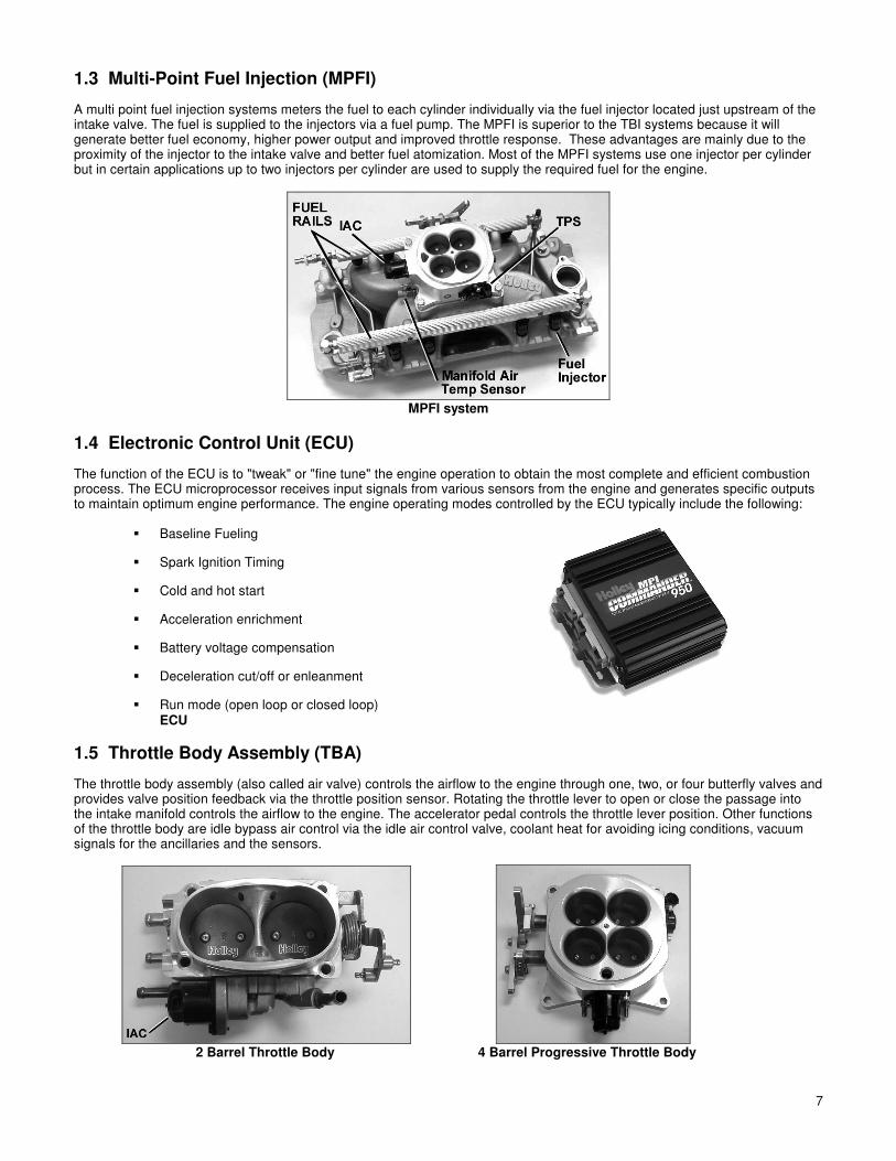
1.3 Multi-Point Fuel Injection (MPFI)
A multi point fuel injection systems meters the fuel to each cylinder individually via the fuel injector located just upstream of the intake valve. The fuel is supplied to the injectors via a fuel pump. The MPFI is superior to the TBI systems because it will generate better fuel economy, higher power output and improved throttle response. These advantages are mainly due to the proximity of the injector to the intake valve and better fuel atomization. Most of the MPFI systems use one injector per cylinder but in certain applications up to two injectors per cylinder are used to supply the required fuel for the engine.
MPFI system
1.4 Electronic Control Unit (ECU)
The function of the ECU is to "tweak" or "fine tune" the engine operation to obtain the most complete and efficient combustion process. The ECU microprocessor receives input signals from various sensors from the engine and generates specific outputs to maintain optimum engine performance. The engine operating modes controlled by the ECU typically include the following:
Baseline Fueling Spark Ignition Timing
Cold and hot start
Acceleration enrichment
Battery voltage compensation
Deceleration cut/off or enleanment
Run mode (open loop or closed loop) ECU
1.5 Throttle Body Assembly (TBA)
The throttle body assembly (also called air valve) controls the airflow to the engine through one, two, or four butterfly valves and provides valve position feedback via the throttle position sensor. Rotating the throttle lever to open or close the passage into the intake manifold controls the airflow to the engine. The accelerator pedal controls the throttle lever position. Other functions of the throttle body are idle bypass air control via the idle air control valve, coolant heat for avoiding icing conditions, vacuum signals for the ancillaries and the sensors.
2 Barrel Throttle Body 4 Barrel Progressive Throttle Body

8 8
1.6 Fuel Injectors
There are basically two approaches in delivering the fuel to the engine: • Above the throttle plate as in throttle body injection • In the intake port toward the intake valves as in multi-point injection
The fuel injector is continuously supplied with pressurized fuel from the electric fuel pump. The pressure to the injector is maintained constant by the fuel pressure regulator. The fuel injector is an electric solenoid valve that when driven by the ECU delivers a metered quantity of fuel into the intake manifold. The ECU controls the fuel flow by opening and closing the injector. The time the injector is open is defined as pulse width. The time the injector is driven into an open condition is determined by the following sensor inputs:
• Engine RPM • Oxygen sensor feedback voltage • Throttle position (TPS) • Intake air charge temperature • Manifold absolute pressure or mass air flow • Battery voltage • Engine coolant temperature
1.6.1 Bottom-Fed Fuel Injector NOTE: This is typically used in TBI systems.
This electromagnetic valve meters fuel into the intake manifold proportional to the air being induced into the engine. When the valve is energized, the electromagnetic force generated by the solenoid lifts the pintle/ball from the seat. Fuel under pressure is then injected into the throttle body bore. For throttle body injection, a hollow conical spray is required to aim the metered flow around the throttle valve.
Bottom-Fed Fuel Injector Top-Fed Fuel Injector
1.6.2 Top-Fed Fuel Injector NOTE: This is typically used in MPFI systems.
When the ECU activates this electromagnetic valve, the injector meters and atomizes fuel in front of the intake valve. The fuel enters the top and is discharged via the metering orifice at the bottom at high pressure. The spray geometry and cross sectional area is specific to the engine application. For MPFI system, a solid spray geometry is required to avoid fuel wall wetting.
In general there are three injector metering design configuration:
1 Pintle injector. This is one of the first fuel injector designs applied to automotive fuel engine management technology.
The fuel flow is metered via an annular orifice between the pintle and the seat. The tip of the pintle has the function of generating the required spray geometry. Pintle type injectors are very susceptible to carbon deposit and have slowly been replaced by director plate metering technology. A conical seat between the plunger and the seat achieves the seal.
2 Disk injector. The disc injector design is different from the above type because a disc replaces the plunger. Sealing is
achieved by seating the disc against the protrusion of the metering orifice. The main advantage of the disc is the lower mass and it is perceived that it can reciprocate at higher frequencies than a plunger. Recent advances in solenoid and plunger manufacturing technology have significantly reduced the weight disparity between the disc and plunger designs. These injectors make use of the director disc design to achieve the required flow and spray geometry.
3 Ball-on-a-stick injector. This metering design is mostly used in the director plate application. The seal is achieved
between a conical seat and a spherical plunger. The director plate’s function is metering the fuel and generating the required spray geometry. Fuel flow is adjusted by the size of the hole machined into the director plate and the spray geometry is adjusted by the orientation of the holes in the director plate. Because the metering components are not exposed to the intake manifold environment, the injector is less susceptible to carbon deposits. All Holley injectors are ball-on-a-stick style.
According to the solenoid design and metering requirements the injectors are further defined into two main categories: 1. High-impedance injectors 2. Low-impedance injectors
1.6.3 High-Impedance Injectors
9
Depending of the brand of the injector, the electric resistance of the coil is in the range 12 to 16 Ohms. In general the high- impedance injector are rated for static fuel flows of 12 to 50 lb./hr. The high-impedance injectors are used with ECUs that are designed with saturation injector drivers. The advantage of using saturation drivers is that the currents running through the ECU circuits and the injectors are relatively low, thus generating less heat. The disadvantage of saturation drivers is that the driver has a slower response time, which could affect the full utilization of such a system at very high engine RPM (two stroke engine applications and four stroke engine applications of 10000RPM and above).
1.6.4 Low-Impedance Injectors
Depending of the brand of the injector, the electric resistance of the coil is in the range 1.2 to 4.0 Ohms. In general the high- impedance injector are rated for static fuel flows of 55 to 160 lb./hr. The low impedance injectors are designed to be run with an ECU that employs peak and hold injector drivers (also called current sensing or current limiting drivers). The advantage of these drivers is that they limit the current in the injector and therefore reduce the heat generation in the ECU. In general, most bottom-fed injectors are of the low impedance design.
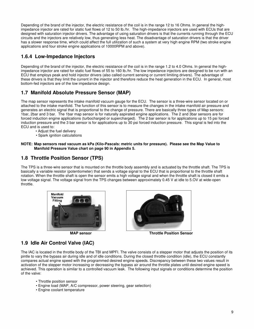
1.7 Manifold Absolute Pressure Sensor (MAP)
The map sensor represents the intake manifold vacuum gauge for the ECU. The sensor is a three-wire sensor located on or attached to the intake manifold. The function of this sensor is to measure the changes in the intake manifold air pressure and generates an electric signal that is proportional to the change of pressure. There are basically three types of Map sensors: 1bar, 2bar and 3 bar. The 1bar map sensor is for naturally aspirated engine applications. The 2 and 3bar sensors are for forced induction engine applications (turbocharged or supercharged). The 2 bar sensor is for applications up to 15 psi forced induction pressure and the 3 bar sensor is for applications up to 30 psi forced induction pressure. This signal is fed into the ECU and is used to: • Adjust the fuel delivery • Spark ignition calculations NOTE: Map sensors read vacuum as kPa (Kilo-Pascals: metric units for pressure). Please see the Map Value to
Manifold Pressure Value chart on page 90 in Appendix 5.
1.8 Throttle Position Sensor (TPS) The TPS is a three-wire sensor that is mounted on the throttle body assembly and is actuated by the throttle shaft. The TPS is basically a variable resistor (potentiometer) that sends a voltage signal to the ECU that is proportional to the throttle shaft rotation. When the throttle shaft is open the sensor emits a high voltage signal and when the throttle shaft is closed it emits a low voltage signal. The voltage signal from the TPS changes between approximately 0.45 V at idle to 5.OV at wide-open throttle.
MAP sensor Throttle Position Sensor
1.9 Idle Air Control Valve (IAC) The IAC is located in the throttle body of the TBI and MPFI. The valve consists of a stepper motor that adjusts the position of its pintle to vary the bypass air during idle and of idle conditions. During the closed throttle condition (idle), the ECU constantly compares actual engine speed with the programmed desired engine speeds. Discrepancy between these two values result in activation of the stepper motor increasing or decreasing the bypass air around the throttle plates until desired engine speed is achieved. This operation is similar to a controlled vacuum leak. The following input signals or conditions determine the position of the valve:
• Throttle position sensor • Engine load (MAP, A/C compressor, power steering, gear selection) • Engine coolant temperature

10 10
Bolt-In IAC Screw-In IAC
1.10 Manifold Air Temperature Sensor The air charge sensor is located in the engine air intake to sense the air induced into the engine manifold. The sensor consists of a thermistor, which generates a voltage signal, that is proportional to the air temperature. This voltage signal is used by the ECU to calculate the air density and using these results to adjust the fueling levels for a particular engine load. A function of the air temperature signal is to:
• Adjust fueling during cold start based on air temperature
1.11 Coolant Temperature Sensor The coolant temperature sensor is a two-wire sensor that is threaded into the engine block and is in direct contact with the coolant. The function of this sensor is to generate a signal that the ECU uses to adjust the fueling levels required for the operation of the engine and operate ancillaries. The thermistor contained in the sensor generates an electric signal that is proportional to the coolant temperature. Other functions of the coolant temperature signal are:
• Idle speed adjustment via the IAC • Modify spark advance • Electric cooling fan operation
1.12 Oxygen Sensor The oxygen sensor (also known as a Lambda sensor) is located in the exhaust manifold and its function is to measure the oxygen content in the exhaust gases. There are two major types of oxygen sensors, commonly referred to “narrow-band” and “wide-band” oxygen sensors. Both will be briefly described below. A narrow-band oxygen sensor is an electrochemical cell, which develops a voltage signal between its two electrodes that is proportional to the oxygen content in the exhaust gases. The oxygen sensor adjusts and maintains an optimum air fuel mixture to control the exhaust emission and the fuel economy. When the oxygen content in the exhaust is high due to a lean mixture, the output voltage of the sensor is close to zero. If the fuel air mixture is on the rich side, the oxygen content in the exhaust is low and the output voltage of the sensor approaches 1.0 volts. Holley uses a 3-wire (heated) O2 sensor. A wide-band oxygen sensor requires addition circuitry for it to function. A wide-band sensor can accurately indicate actual air/fuel ratios between approximately 10:1 to 20:1. This type of sensor is most desirable but the associtated costs are much higher than a narrow-band sensor. Most Holley systems are offered with either a narrow-band or wide-band oxygen sensor. Upgrade kits are availbable to convert to the wide-band sensor.
Manifold Air Temperature Sensor Coolant Temperature Sensor Three-Wire Heated Oxygen Sensor
1.13 Electric In-line Fuel Pump The function of the electric fuel pump is to deliver pressurized fuel to the fuel injection system. The ECU activates the fuel pump relay to operate the fuel pump when the ignition switch is in the On or start position. The pumps are designed to match certain flow and pressure specification for the engine application. In TBI applications, the fuel pump must supply enough fuel flow for the engine Wide-Open Throttle (WOT) output at 15 to 20 psi. In multi-port applications, the fuel pump must be able to supply enough fuel at full engine load to maintain at least 43.5 psi at the fuel rail. At idle, the fuel pressure regulator must be able to return the excess fuel to the tank and maintain the required system pressure. Most of the cars prior to 1987 use an in-line external electric fuel pump.

11
In-line Fuel Pump High-Flow In-line Fuel Pump High Performance Race Pump
1.14 Electric In-tank Fuel Pump Almost all car applications after 1987 designed their fuel pump assembly inside the fuel tank. The advantage of having the fuel pump in the fuel tank is mainly lower noise, lower potential leakage problems, and less mounting sensitivity of the pump with respect to lift of fuel from the tank. The in-tank pump went through several designs evolving from a simple "pump on a stick" to a complex in-tank, fuel-sending module. The new designs combine the high-pressure electric fuel pump, noise isolation, and a fuel level sensor into one compact modular package. This new design also helps in reducing hydrocarbon emissions. The hot gasoline returning from the fuel system is returned to the reservoir surrounding the fuel pump. By returning the hot fuel to the reservoir heating of the bulk fuel in the fuel tank is avoided, thus reducing the evaporation of the high volatile portions in the fuel. At present, all fuel tank modules are designed and serviced as a complete unit. If the pump or fuel level sensor fails, the entire unit will have to be changed. NOTE: Never use an in-tank, low-pressure fuel pump in conjunction with an external high-pressure fuel pump. The low-
pressure, in-tank fuel pump will become a restriction to the external, high-pressure fuel pump. This condition will result in fuel starvation and engine damage.
Aftermarket In-tank Pump Stock-style pump module
1.15 Fuel Pump Inlet Filter The function of this filter is to eliminate any impurities that might harm the fuel pump. In the in-line fuel pump type, this filter is external to the fuel tank and is in a replaceable cartridge filter. In the in-tank fuel pumps, the fuel filter is in the form of a sock and is directly attached to the pump in the "pump on a stick" version and attached to the fuel pump module in the module version. These filters have a rating of 120-150 microns.
NOTE: This fuel filter is required to avoid fuel pump damage.
1.16 Main Fuel Filter The function of this filter is to eliminate any contaminants after the fuel pump. These are either small enough to pass through the fuel filter of the pump inlet or are generated by the fuel pump. This fuel filter is also of the cartridge type, but is designed to sustain much higher fuel pressures than the fuel pump inlet filter. These filters have a rating of 10 microns. NOTE: This fuel filter is required to avoid fuel injector damage.
1.17 Fuel Pressure Regulator Fuel system pressure is maintained by the regulator, while excess fuel is returned to the fuel tank. The regulator consists of two chambers separated by a diaphragm assembly. On the fuel side of the diaphragm, a throttling valve is employed to increase or restrict fuel flow as the fuel pressure fluctuates. The other side contains a spring with an adjustment screw that is set at the factory for correct system pressure and flow. This chamber is connected to the intake manifold in MPFI systems to reference the vacuum in the manifold during engine operation. This pressure reference is required to maintain a constant differential pressure across the metering orifice of the fuel injector. On TBI systems, the regulator is in the throttle body assembly.

12 12
Fuel Pump Inlet Filter Main Fuel Filter Fuel Pressure Regulator
1.18 Fuel Rails
The function of the fuel rails is to deliver fuel at system pressure to the fuel injectors and to retain the fuel injectors on the intake manifold. At the end of the rails, there is the pressure regulator that maintains a constant pressure at the fuel injector regardless of the fuel being injected. The location of the fuel regulator with respect to the fuel rail and the internal volume of the fuel rail is important in maintaining the fuel pressure stability in the system.
Fuel Rails
1.19 Fuel Injection Control Methods
1.19A Speed Density EFI Systems
Speed density EFI systems use input from the MAP sensor and engine rpm to determine the base amount of fuel to inject. The Commander 950 PRO uses these inputs to look up a value from the base fuel table. This method is used on many OEM vehicles.
1.19B Alpha-N EFI Systems Alpha-N EFI systems use input from the Throttle Position Sensor (TPS) and engine rpm to determine the base amount of fuel to inject. The Commander 950 PRO uses these inputs to look up a value from the base fuel table. This method is used only for race cars that have very low manifold vacuum. This method does not sense changes in engine load well and is not recommended for street driven vehicles.
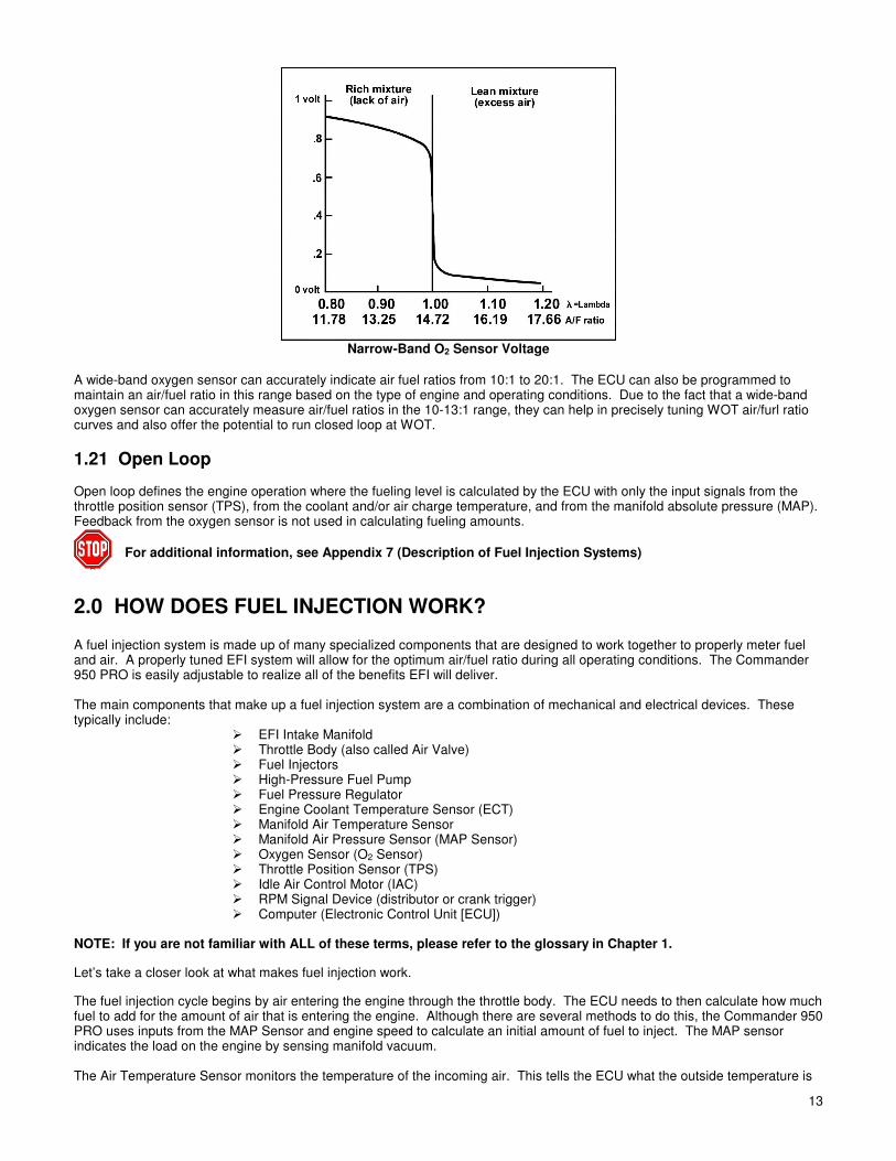
1.20 Closed Loop Closed loop defines the engine operation where the fueling level is calculated and corrected by the ECU based on the signal from the 02 sensor (lambda sensor). Narrow-band oxygen sensor can accurately indicate an air/fuel ratio of 14.7:1 that corresponds to an output voltage of approximately .45 volts. When the 02 sensor emits a voltage signal above 0.45V due to a rich mixture in the exhaust manifold, the ECU reduces the fueling level by reducing the pulse width of the injector. The 02 sensor voltage (lambda sensor voltage) is the feedback that modifies the fuel control program that is based on other signals. When this signal is below .45V the ECU adds fuel.
13
Narrow-Band O2 Sensor Voltage
A wide-band oxygen sensor can accurately indicate air fuel ratios from 10:1 to 20:1. The ECU can also be programmed to maintain an air/fuel ratio in this range based on the type of engine and operating conditions. Due to the fact that a wide-band oxygen sensor can accurately measure air/fuel ratios in the 10-13:1 range, they can help in precisely tuning WOT air/furl ratio curves and also offer the potential to run closed loop at WOT.
1.21 Open Loop Open loop defines the engine operation where the fueling level is calculated by the ECU with only the input signals from the throttle position sensor (TPS), from the coolant and/or air charge temperature, and from the manifold absolute pressure (MAP). Feedback from the oxygen sensor is not used in calculating fueling amounts.
For additional information, see Appendix 7 (Description of Fuel Injection Systems)
2.0 HOW DOES FUEL INJECTION WORK? A fuel injection system is made up of many specialized components that are designed to work together to properly meter fuel and air. A properly tuned EFI system will allow for the optimum air/fuel ratio during all operating conditions. The Commander 950 PRO is easily adjustable to realize all of the benefits EFI will deliver. The main components that make up a fuel injection system are a combination of mechanical and electrical devices. These typically include:
EFI Intake Manifold Throttle Body (also called Air Valve) Fuel Injectors High-Pressure Fuel Pump Fuel Pressure Regulator Engine Coolant Temperature Sensor (ECT) Manifold Air Temperature Sensor Manifold Air Pressure Sensor (MAP Sensor) Oxygen Sensor (O2 Sensor) Throttle Position Sensor (TPS) Idle Air Control Motor (IAC) RPM Signal Device (distributor or crank trigger) Computer (Electronic Control Unit [ECU])
NOTE: If you are not familiar with ALL of these terms, please refer to the glossary in Chapter 1.
Let’s take a closer look at what makes fuel injection work.
The fuel injection cycle begins by air entering the engine through the throttle body. The ECU needs to then calculate how much fuel to add for the amount of air that is entering the engine. Although there are several methods to do this, the Commander 950 PRO uses inputs from the MAP Sensor and engine speed to calculate an initial amount of fuel to inject. The MAP sensor indicates the load on the engine by sensing manifold vacuum. The Air Temperature Sensor monitors the temperature of the incoming air. This tells the ECU what the outside temperature is
14 14
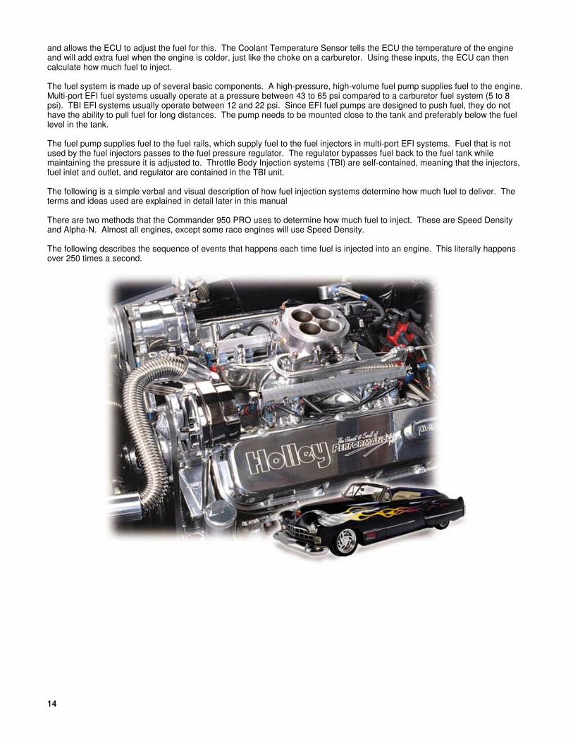
and allows the ECU to adjust the fuel for this. The Coolant Temperature Sensor tells the ECU the temperature of the engine and will add extra fuel when the engine is colder, just like the choke on a carburetor. Using these inputs, the ECU can then calculate how much fuel to inject. The fuel system is made up of several basic components. A high-pressure, high-volume fuel pump supplies fuel to the engine. Multi-port EFI fuel systems usually operate at a pressure between 43 to 65 psi compared to a carburetor fuel system (5 to 8 psi). TBI EFI systems usually operate between 12 and 22 psi. Since EFI fuel pumps are designed to push fuel, they do not have the ability to pull fuel for long distances. The pump needs to be mounted close to the tank and preferably below the fuel level in the tank. The fuel pump supplies fuel to the fuel rails, which supply fuel to the fuel injectors in multi-port EFI systems. Fuel that is not used by the fuel injectors passes to the fuel pressure regulator. The regulator bypasses fuel back to the fuel tank while maintaining the pressure it is adjusted to. Throttle Body Injection systems (TBI) are self-contained, meaning that the injectors, fuel inlet and outlet, and regulator are contained in the TBI unit. The following is a simple verbal and visual description of how fuel injection systems determine how much fuel to deliver. The terms and ideas used are explained in detail later in this manual There are two methods that the Commander 950 PRO uses to determine how much fuel to inject. These are Speed Density and Alpha-N. Almost all engines, except some race engines will use Speed Density. The following describes the sequence of events that happens each time fuel is injected into an engine. This literally happens over 250 times a second.
15
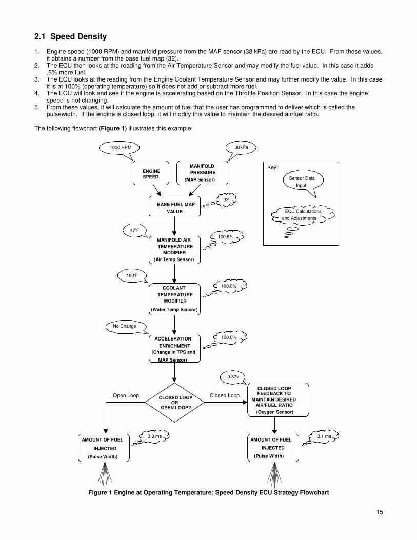
2.1 Speed Density 1. Engine speed (1000 RPM) and manifold pressure from the MAP sensor (38 kPa) are read by the ECU. From these values,
it obtains a number from the base fuel map (32). 2. The ECU then looks at the reading from the Air Temperature Sensor and may modify the fuel value. In this case it adds
.8% more fuel. 3. The ECU looks at the reading from the Engine Coolant Temperature Sensor and may further modify the value. In this case
it is at 100% (operating temperature) so it does not add or subtract more fuel. 4. The ECU will look and see if the engine is accelerating based on the Throttle Position Sensor. In this case the engine
speed is not changing. 5. From these values, it will calculate the amount of fuel that the user has programmed to deliver which is called the
pulsewidth. If the engine is closed loop, it will modify this value to maintain the desired air/fuel ratio. The following flowchart (Figure 1) illustrates this example:
BASE FUEL MAP
VALUE
100.8%
1000 RPM 38kPa
32
47°F
AMOUNT OF FUEL
INJECTED
(Pulse Width)
3.1 ms
ENGINE
SPEED
MANIFOLD
PRESSURE
(MAP Sensor)
MANIFOLD AIR
TEMPERATURE
MODIFIER
(Air Temp Sensor)
ACCELERATION
ENRICHMENT
(Change in TPS and
MAP Sensor)
COOLANT
TEMPERATURE
MODIFIER
(Water Temp Sensor)
100.0%
0.82v
CLOSED LOOPFEEDBACK TO
MAINTAIN DESIRED
AIR/FUEL RATIO
(Oxygen Sensor)
CLOSED LOOPOR
OPEN LOOP?
AMOUNT OF FUEL
INJECTED
(Pulse Width)
3.8 ms
Open Loop Closed Loop
180°F
100.0%
No Change
Sensor Data
Input
ECU Calculations
and Adjustments
Key:
Figure 1 Engine at Operating Temperature; Speed Density ECU Strategy Flowchart
16 16
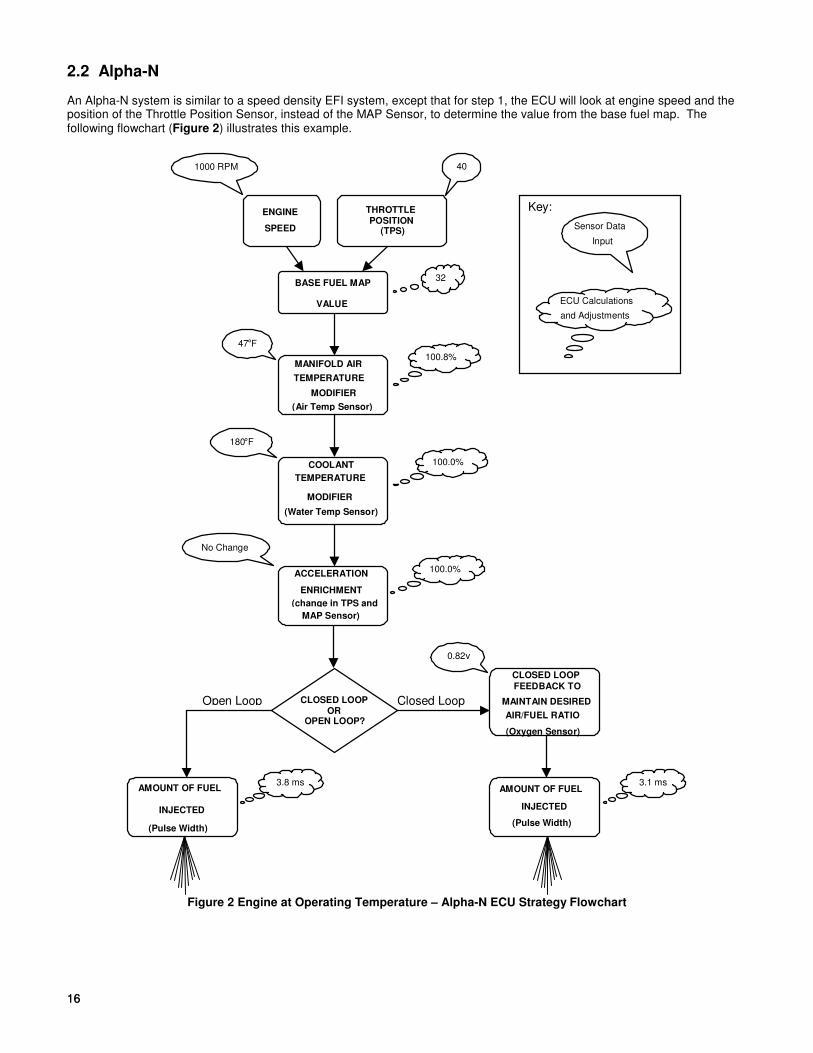
2.2 Alpha-N An Alpha-N system is similar to a speed density EFI system, except that for step 1, the ECU will look at engine speed and the position of the Throttle Position Sensor, instead of the MAP Sensor, to determine the value from the base fuel map. The following flowchart (Figure 2) illustrates this example.
100.8%
1000 RPM 40
47°F
ENGINE
SPEED
THROTTLEPOSITION
(TPS)
MANIFOLD AIR
TEMPERATURE
MODIFIER
(Air Temp Sensor)
ACCELERATION
ENRICHMENT
(change in TPS and
MAP Sensor)
COOLANT
TEMPERATURE
MODIFIER
(Water Temp Sensor)
100.0%
180°F
BASE FUEL MAP
VALUE
32
AMOUNT OF FUEL
INJECTED
(Pulse Width)
3.1 ms
0.82v
CLOSED LOOP
FEEDBACK TO
MAINTAIN DESIRED
AIR/FUEL RATIO
(Oxygen Sensor)
CLOSED LOOPOR
OPEN LOOP?
AMOUNT OF FUEL
INJECTED
(Pulse Width)
3.8 ms
Open Loop Closed Loop
100.0%
No Change
Sensor Data
Input
ECU Calculations
and Adjustments
Key:
Figure 2 Engine at Operating Temperature – Alpha-N ECU Strategy Flowchart

17
3.0 SKILL LEVEL REQUIRED Installation of the COMMANDER 950 PRO intake system and the ECU requires approximately the same level of skill and experience to replace or service an induction system consisting of a carburetor and conventional intake manifold (as well as basic wiring skills for the installations of the ECU). Tuning of the system requires basic computer skills and a basic knowledge of engine and fuel injection principles. The information needed to tune this system is included in this manual. Read it thoroughly. Installation of the actual EFI system hardware is included in hardware installation manuals with each kit. Tuning your EFI system is an ongoing project, until you get it dialed in for all conditions. Be patient. NOTICE: If you are not absolutely certain that you have the skills and experience required to perform these
procedures, we strongly recommend you have this system installed and tested by a technician with specialized training in EFI and fuel systems service.
4.0 TOOLS REQUIRED FOR INSTALLATION The following is a list of materials, which may be needed, depending on the application. Laptop PC w/ Windows 95, 98, ME, NT, 2000, XP, and serial communications port (min. graphics required=800 x 600) Digital Volt-Ohm meter Screwdriver set Drill and assorted bit sizes Hole saw (2”) or Greenlee punch Timing/Advance Light (Dial back recommended) Standard wrench set Standard socket set Fuel pressure gauge Wire terminal pliers Electrical tape Zip ties 14 gauge wire The following is a list of parts that may be required to complete this installation (dependent on the application). 534-138 GM small cap HEI adapter (included with GM MFPI kits) 534-139 Ford TFI adapter (included with 5.0L Ford kits) 538-13 Two bar MAP sensor for applications with 0-14.7 PSI of boost 538-23 Three bar MAP sensor for applications with 14.7-29.4 PSI of boost 534-136 Knock Sensor wiring kit 534-134 Cooling Fan Relay kit 534-135 Crank Trigger wiring kit N/A Aftermarket Crank Trigger (required for LT1 engines)
5.0 ELECTRICAL CONNECTIONS
Proper installation of the wiring harness and all electrical connections is critical for proper and reliable operation of any EFI system. Damage to the ECU can also result from improper wiring.
Wiring diagrams are provided for reference during the connection of electrical components. These diagrams show the connectors included with the wiring harness and table shows the color codes and connections for all of the loose wires without connectors. See Appendix 10 for the wiring harness diagram. NOTE: Some of the wiring schematics include wiring for optional kits, such as a cooling fan kit.

18 18
5.1 Step-by-Step Wiring Harness Installation NOTE: It is advised to leave the battery completely disconnected until the installation of the entire system is
completed. 1. ECU MOUNTING – The ECU should be mounted as far away from the ignition box as is feasible (minimum 6”). The ECU
must be installed in the vehicle in a location free from moisture and dirt. The glove box area is usually a good location in most vehicles. There are sheet metal screws included for this purpose. The ECU must be grounded. If you mount it on a non-metallic surface (ex. fiberglass body), run a 14 gauge ground wire to the chassis.
2. HOLLEY WIDE-BAND OXYGEN SENSOR CONTROLLER – This unit can be mounted either inside the vehicle or engine
compartment. Do not put in direct contact with water or road debris and keep away from excessive heat. 2A. NON-HOLLEY WIDE-BAND OXYGEN SENSOR CONTROLLER – If using a non-Holley wide-band oxygen sensor
controller, refer to the manufacturer’s instructions for its installation. In order for the Commander 950 PRO to use such a device for closed loop operation, a calibrated 0-5 volt output from the wide-band sensor controller must be connected to the purple O2 sensor signal wire on the Commander 950 PRO. The red power wire and black ground wire also contained in the O2 sensor 3 pin weatherpack connector can also be used to power and ground the wide-band controller unit. This is desirable so that the wide-band controller is only powered when the engine is running. If the wide-band controller has a separate analog output ground, it is advisable to connect this to a very good vehicle chassis ground. See the wiring schematics in the back to find the O2 sensor connector. Make sure the proper voltage vs. air/fuel curve is entered into the O2 parameters. It is the responsibility of the customer to make sure this curve is accurate or engine damage can result.
3. WIRING HARNESS - The wiring harness will need to be fed through the firewall in the vehicle. Drill a 2 inch diameter hole
and feed the harness through it. A grommet is provided for this hole so the harness will not be damaged. Be very careful that the hole you drill does not interfere with items like wiring harnesses, heating, or AC systems.
4. CONNECT WIRING HARNESS - After the harness is routed through the hole connect it to the ECU. Route the rest of the
harness into the engine compartment. 5. INSTALL RELAY - A system power relay is included. The relay holder for it is about 3 feet from the ECU connection. The
relay can be mounted inside the interior or in the engine compartment. Decide where you want it and secure the relay. A sheet metal screw is provided for this purpose. Be careful that you don’t drill through the firewall and damage something. Mount the relay and attach it to the harness.
6. INSTALL FUSE - The 15 amp fuse needs to be installed in the fuse holder. The fuse is included and the fuse holder is
located near the ECU. Install it now.
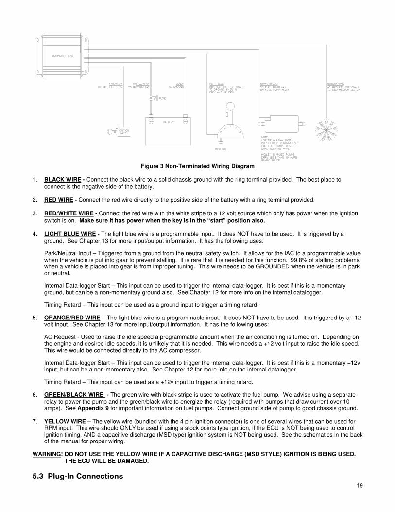
5.2 Non-Terminated Wire Connection Next, the non-terminated wires will be connected (Figure 3). The following chart provides an overview. However, each one will be described separately.
NON-TERMINATED WIRE COLOR AND DESCRIPTION WIRE CONNECTION LOCATION
Black Ground connection
Red with fuse +12 Volt, attach to the battery
Red/White Switched +12 volt power (make sure this has power during cranking also)
Orange/Red AC Request or other programmable inputs [+12v] (this is an optional wire)
Light Blue Park/Neutral or other programmable inputs [Ground] (this is an optional wire)
Green Black +12 volt fuel pump or fuel pump relay
Yellow Wire See text below
WARNING! DO NOT USE THE YELLOW WIRE IF A CAPACITIVE DISCHARGE (MSD STYLE) IGNITION IS BEING USED. THE ECU WILL BE DAMAGED.
WARNING! Keep all wires away from hot exhaust components. Bare or frayed wires can result in electrical short circuits, which can cause system or vehicle damage, or a fire hazard resulting in property damage, serious injury, and/or death.
19
Figure 3 Non-Terminated Wiring Diagram
1. BLACK WIRE - Connect the black wire to a solid chassis ground with the ring terminal provided. The best place to
connect is the negative side of the battery. 2. RED WIRE - Connect the red wire directly to the positive side of the battery with a ring terminal provided. 3. RED/WHITE WIRE - Connect the red wire with the white stripe to a 12 volt source which only has power when the ignition
switch is on. Make sure it has power when the key is in the “start” position also. 4. LIGHT BLUE WIRE - The light blue wire is a programmable input. It does NOT have to be used. It is triggered by a
ground. See Chapter 13 for more input/output information. It has the following uses:
Park/Neutral Input – Triggered from a ground from the neutral safety switch. It allows for the IAC to a programmable value when the vehicle is put into gear to prevent stalling. It is rare that it is needed for this function. 99.8% of stalling problems when a vehicle is placed into gear is from improper tuning. This wire needs to be GROUNDED when the vehicle is in park or neutral.
Internal Data-logger Start – This input can be used to trigger the internal data-logger. It is best if this is a momentary ground, but can be a non-momentary ground also. See Chapter 12 for more info on the internal datalogger.
Timing Retard – This input can be used as a ground input to trigger a timing retard.
5. ORANGE/RED WIRE – The light blue wire is a programmable input. It does NOT have to be used. It is triggered by a +12 volt input. See Chapter 13 for more input/output information. It has the following uses:
AC Request - Used to raise the idle speed a programmable amount when the air conditioning is turned on. Depending on the engine and desired idle speeds, it is unlikely that it is needed. This wire needs a +12 volt input to raise the idle speed. This wire would be connected directly to the AC compressor.
Internal Data-logger Start – This input can be used to trigger the internal data-logger. It is best if this is a momentary +12v input, but can be a non-momentary also. See Chapter 12 for more info on the internal datalogger.
Timing Retard – This input can be used as a +12v input to trigger a timing retard.
6. GREEN/BLACK WIRE - The green wire with black stripe is used to activate the fuel pump. We advise using a separate relay to power the pump and the green/black wire to energize the relay (required with pumps that draw current over 10 amps). See Appendix 9 for important information on fuel pumps. Connect ground side of pump to good chassis ground.
7. YELLOW WIRE – The yellow wire (bundled with the 4 pin ignition connector) is one of several wires that can be used for RPM input. This wire should ONLY be used if using a stock points type ignition, if the ECU is NOT being used to control ignition timing, AND a capacitive discharge (MSD type) ignition system is NOT being used. See the schematics in the back of the manual for proper wiring.
WARNING! DO NOT USE THE YELLOW WIRE IF A CAPACITIVE DISCHARGE (MSD STYLE) IGNITION IS BEING USED. THE ECU WILL BE DAMAGED.
5.3 Plug-In Connections

20 20
NOTE: See Appendix 10 for diagrams.
1. Air Charge Temperature Sensor – Find the 2 wire connector with the BLUE and BLACK/WHITE wires. Plug this into the air temperature sensor, which is located in the intake manifold on MPFI applications. For TBI applications, the air temp sensor is located next to the injector pod.
2. Coolant Temperature Sensor - Find the 2 wire connector with the BROWN and BLACK/WHITE wires. Plug this into the coolant temperature sensor, which is located in a coolant passage.
3. Throttle Position Sensor (TPS) - Find the 3 wire connector with the BLACK/WHITE, GREEN, and ORANGE wires. Plug this into the TPS located on the throttle body.
4. Idle Air Control (IAC) Motor – Find the 4 wire connector with the PURPLE wires. Plug this into the IAC Motor, which is located on the throttle body.
5. Narrow-Band Oxygen Sensor (O2)* – Plug this into the oxygen sensor, located in the exhaust system. It is the 3 wire connector with a RED, PURPLE, and BLACK wire. Route the wire away from heat to avoid damage to the sensor or wire.
6. Wide-Band Oxygen Sensor* – Plug the 3 wire connector with a RED, PURPLE, and BLACK wire into the 3 wire connector from the Holley wide-band oxygen sensor controller. Plug the 8 wire connector from the wide-band oxygen sensor controller into the wide-band oxygen sensor. The four-wire connector is for a display (not included) *A system includes either a narrow-band oxygen sensor or a wide-band oxygen sensor depending on system options.
7. Manifold Absolute Pressure (MAP) Sensor – Locate the 3 wire flat connector with the following color wires: BLACK/WHITE, ORANGE, and RED/BLACK. Plug this connector into the MAP sensor. Two and Three bar MAP sensors are optional in some kits. The base kits come with a one bar MAP sensor. If a two or three bar MAP sensor is used, it must be selected in the “Engine” parameters when you get the computer hooked up. The two and three bar MAP sensors should include a connector that may have to be changed on the harness.
8. Injector Harness – The harness for the fuel injectors is separate from the main harness. For multi-port systems, route the injector harness as desired. This harness plugs into the 5 wire connector on the main harness. TBI systems also plug directly into this connector.
5.4 Ignition Wiring NOTE: Appendix 10 in the back of the manual includes wiring diagrams to wire the following:
Large Cap Computer Controlled GM HEI – Plugs directly into 4 pin weatherpack ignition connector in Comm 950 harness.
Small Cap Computer Controlled GM HEI – Requires adapter (PN 534-138) that plugs into the 4 pin weatherpack connector in the Commander 950 harness. This adapter is included with complete Chevrolet SB and BB Multi-port EFI systems.
Ford TFI – Works with any Ford TFI electronic distributor. Requires adapter (PN 534-139) that plugs into the 4 pin weatherpack connector in the Commander 950 harness. This adapter is included with complete Ford Multi-port EFI systems.
Large Cap Non-Computerized HEI – This distributor uses mechanical and vacuum advance and is not capable of having the Commander 950 control timing.
Crank Trigger CD Ignition Systems – The Commander 950 can control the timing on any engine that uses a crank trigger (magnetic or Hall effect) and capacitive discharge ignition box.
Non-Computer Controlled Inductive Ignition Systems – Any inductive (non-CD) ignition system (most stock ignition systems
are inductive) can be used to provide an RPM signal to the Commander 950. These systems will not allow the Commander 950 to control ignition timing. Points ignition and the Mallory Uni-lite systems fall into this category.
Magnetic Pickup Distributors with Mechanical Advance – Standard magnetic pickup mechanical advance distributors such as a Holley or MSD can be used with a CD ignition system. The C950 will not be able to control timing. Connect the yellow/black ignition wire to the tach output connection on the CD box.
GM LT1 Engines – These engines require the use of a crank trigger and CD ignition box. Follow the wiring instructions for a crank trigger CD system.
NOTE: It is not advisable to use a magnetic pickup distributor to directly feed the magnetic trigger input of the C950. If the magnetic pickup distributor is connected to the C950 via the inductive pickup trigger wires, the pickup/rotor/cap phasing must be corrected. This operation may require a phaseable cap or rotor or possibly machining to the distributor and is

21
therefore beyond the scope of most users. Even with the phasing corrected, the electrical noise inside the cap may be strong enough to cause tuning problems. It is advised to use a crank trigger system or a computer-controlled distributor.
Reconnect the battery cable and check voltages. NOTE: NEVER CONNECT THE YELLOW WIRE TO A CAPACITIVE DISCHARGE IGNITION SYSTEM.
6.0 SOFTWARE INSTALLATION, SOFTWARE OPERATIONAL DESCRIPTION, COMPUTER OPERATION, & FUEL MAP DOWNLOADING
An IBM compatible laptop computer is required for use with the COMMANDER 950 PRO. The computer must be capable of running Windows 95, 98, ME, 2000, XP or Windows NT. The laptop must also have a graphics resolution of at least 800 x 600 to view all areas of the screen. The computer must have a Comm. port.
6.1 Software Installation
6.1.1 Windows 95, 98, NT, ME, 2000, XP
1. Insert CD Rom into the CD drive of your laptop. The CD will run automatically.
2. Follow on screen prompts to load the C950 software.
3. An electronic version of this manual is also on the CD. To open the manual, go to “My Computer” right click on the CD Rom drive, and click on “Explore”. This will bring up the file which can be opened or saved.
6.2 Basic Computer Operation
Once the software is installed, a Commander 950 Pro icon should appear on the main computer screen. When you double-mouse click on this icon, the software should start. There is a communications cable that needs to be hooked up to the ECU (it is connected to the harness near the ECU) for you to program and view data in the ECU. This cable needs to be plugged into the communications (comm) port, which is usually in the back of a laptop computer. If your computer does not have a comm. Port, Holley recommends the use of a Keyspan USB to comm adapter (PN USA19HS). Make sure the laptop is communicating with the USB adapter as comm. Port 1,2,3, or 4. The computer usually recognizes this comm port as comm 1. Sometimes it may be comm 2. The proper port must be selected in the software in order for the computer to communicate with the ECU. If comm 1 does not work, change the software to comm 2.
6.3 Software Operation and Navigation
The Commander 950 PRO is a Windows-based software. It functions the same as all other windows software. Pull-down menus are selected with the mouse. These are then opened to view the various tables.
Software Data Capture – When a window is opened, the software checks for the ECU. If it is present (powered up and connected to the serial cable), the computer will get the latest data from the ECU. This ensures the user and the PC are always using the most up-to-date information. If the ECU is not connected, the PC will just use the information it has in memory. If no map has been loaded into the PC (via file—load operation) and no ECU is present, there will be nothing in memory and zero will be displayed for nearly all variables.
These tables can be edited with the ECU connected and powered or without the ECU powered. With the laptop computer connected and powered, you can tune the vehicle with the engine running and with the vehicle being driven. If the laptop is not connected to the ECU, you can change the files, and then later send the changes to the ECU.
Editing with the ECU Connected and Powered – One of the most important features of the Commander 950 PRO is the ability to make real-time changes when the engine is running. In order to do this, the ECU must be connected to the computer, and the ignition switched on (the engine does not have to be running). When a value is entered and the “Enter” key, Arrow key, or Tab key is pressed, the value is instantly sent to the ECU and the old value is gone.

22 22
Editing with the ECU not Connected – Values can be changed when the computer is not connected or the ignition not switched on. However, for these values to be entered in the ECU, the entire file must be sent to overwrite what data is currently in the ECU. The following shows how to open, send, retrieve, and save a file. When editing tables without being connected to the ECU, you must also press the “Enter” key, Arrow key, or Tab key to enter the value.
Opening a File into the Computer – To open a file into the computer perform the following steps: 1) Select “File” and “Open Data from Disk” 2) Select the file you want to open, either from the hard drive or a disk. (This is explained in “Step-by-Step Initial Startup”). 3) Hit “Enter” or click on “Ok” 4) The file is now in the computer.
Figure 4
Sending a File to the ECU – To send a file to the ECU perform the following steps:
1) Open a file as described above. Do NOT go to any of the other areas in the software, as this will retrieve and corrupt the data that you just opened.
2) Make sure the ignition is on. After the file is opened, immediately go to “File” and “Send ECU Data”. It will take about one minute to send the data. When the hourglass changes back to your mouse pointer, the file has been sent.
Retrieving a File from the ECU – You would want to retrieve a file from the ECU when you want to save it to the hard drive of the computer or to a disk. To retrieve a file, make sure the ignition is on and go to “File” and hit “Retrieve ECU Data”. This pulls the data from the ECU to the computer.
Saving a File to the Computer – It is highly recommended to save your file before making any major changes. If the changes don’t work well you can send the previous file back. To save a file from the ECU, first retrieve it from the ECU and then go to “File” and “Save Data to Disk”. This file will be available to send if you ever need to.
Force Default Values – When loading an older map not made for the PRO software, several of the default values will not be set properly. If these values are not set, an engine will either not start or run very poorly. This feature will allow for these new values to be updated to values that should at least allow for the engine to start and be driveable. To update the values, first load the old map into the ECU. The laptop must be connected and the ignition must be turned on. Under “File”, hit the “Force Default Values” key. This will update the values to usable values. They then can be fine-tuned for the specific application.
Print All – Will print all tables and maps to a printer.
Hot Key Navigating – There are 5 “Hot Keys” that can be used to quickly change from one screen to another. The screens that can be navigated between are the following:
Map Screen Hot Key Fuel Map Screen Control + F Spark Map Screen Control + S Acceleration Enrichment Map Screen Control + A Modifiers Map Screen Control + M Closed Loop Parameters Control + O
NOTE: Remember these. These commands will be needed later on for tuning. You must already be in one of these five screens before you can use the hot keys to navigate to the others.
Mouse Free Navigating – Sometimes a laptop mouse is hard to use. The C950 PRO software can be operated without it. From the main window, press “Alt” and then the underlined letter of the window or menu you want to open (i.e. press “Alt” and then “F” to open the “file menu”). Different locations can be navigated by pressing the “Tab” key. When in any of the windows with tables (such as the fuel and spark tables), it is easier to use the arrow keys, so you can move quickly to the exact spot you want. To exit a window, press the “Esc” key. When making changes, the new value isn’t actually sent until you move off the cell you are working on or press the “Enter” key.
Making Changes to Multiple Cells at Once – In the fuel and spark maps, changes to entire sections of the maps can be made via “cell action” feature. Using the mouse, click on a cell in the area that you wish to modify. Next, click on the diagonally opposite cell. The cells in this region will be highlighted in yellow and a small window will appear. Type the operation that you wish to perform (+ for addition, - for subtraction, * for multiply, / for divide, and % for adding or subtracting a percentage) and the value you wish to modify the cell amount. For example, by typing a “+10”, the ten units will be added to all of the highlighted cells. Typing a “*1.2” would multiply all the highlighted cells by 1.2. This feature is very helpful and should be used when needed.

23
6.4 Base Maps
Base maps are supplied. Choose the one that is closest to your application. If one does not seem to work well, choose another. You will always have to perform additional tuning for the vehicle to operate best. That is the benefit of programmable EFI. This tuning may be small changes or large changes, depending on your engine and vehicle. These base maps will be installed in the Commander 950 PRO directory when the software is installed. There is also an additional sheet supplied that describes what these are for. New base maps can be found on the Holley website (www.holley.com). These are self-extracting zip files. Save them to a directory and double click on them. This will unzip them and allow them to be loaded to the ECU. See the information above on sending these maps to the ECU.
Note that the maps are separated by using a narrow-band or wide-band oxygen sensor. The maps for a narrow-band sensor start with a NB and the wide-band maps start with a WB for systems using a Holley wide-band oxygen sensor. Select depending on which oxygen sensor you have.
6.5 Advanced and Beginning Users
Not all screens may look exactly like they are shown in the manual. Some variables are considered too advanced for the first-time user and are not needed until the tuning process is nearly complete. These variables have been hidden from view. When you are ready to adjust these parameters (and you may never need to use them), go to “About” and then “Version”. Check the “Advanced User” box and all variables will be visible.
7.0 STEP-BY-STEP INITIAL STARTUP INSTRUCTIONS
At this point you should have the mechanical installation complete. The Commander 950 PRO software should be installed in the laptop (Chapter 6.1) you will use for tuning. The next section is the first attempt to start the engine. Base maps are included for different engine combinations. If the base map is close to your application, then the vehicle should fire and run. If the base maps that you try will not start and allow the engine to keep running, go to the detailed tuning information that is included in the Step-by-Step Basic Tuning (Chapter 8.0).
1. CHECK FUSES/RELAYS Make sure the 15 amp fuse is installed in the fuse holder in the main red power wire which is located near the ECU. Make sure the relay is installed in the relay holder.
2. CONNECT COMPUTER CABLE Connect the communications cable to the serial communications port on the computer and to the round connector on the main harness near the ECU.
3. PRIME FUEL SYSTEM Turn the ignition key to “Run”, not start. You should hear the fuel pump energize for about 5 seconds, then shut off. This allows for the pump to pressurize the fuel system. When the vehicle is starting and runs, the pump will turn back on. If you do not hear the pump turn on when the key is turned on, see Appendix 4. After the pump is energized, check the entire fuel system for leaks. You can shut the key off, wait about 10 seconds, then turn it back on to re-energize the pump. It takes 10 seconds in the key “Off” position for the ECU to reset. You may have to do this several times if the entire fuel system is dry. When the system is pressurized, you can hear the speed of the pump slow down. You will also see the pressure come up on a fuel pressure gauge.
4. CHECK FUEL PRESSURE
Do an initial check of the fuel pressure when the key is turned on. See the hardware installation manual for
information on installing a fuel pressure gauge on your particular system. It is critical that the pressure be checked and adjusted. The recommended base setting for Multi-port systems is 44 psi +/-2 psi and Throttle Body Injection systems is 21 psi +/-1 psi. These settings can be raised or lowered if an injector is selected that is too big or too small. Again, you may need to energize the pump a few times if the fuel system is dry.
NOTE: There is a vacuum line going to the fuel pressure regulator. This is needed to compensate for vacuum present in the intake manifold. Make sure you always use this vacuum line. When the engine is running and the vacuum line is hooked to the regulator, the pressure seen on the fuel pressure gauge will be lower depending on how much vacuum is present. 2 inches (Hg) of engine vacuum will lower the fuel pressure 1 psi. For example, 15 inches (Hg) of engine vacuum will lower the fuel pressure about 7 psi. This is normal.
If the pressure is not checked and set, you will possibly have problems later when tuning the engine. There are going to be instances when you will need to increase or decrease the pressure if your injector size is not adequate for your engine. That will be discussed later. At this time, check for fuel leaks. After the engine is started you will then need to re-check for leaks.
24 24
5. IGNITION CHECK It is very important that you are sure that you installed the distributor so that the timing will be close when the engine is first started. If it is not, the vehicle may not start or run very poorly. If you are not sure, review the hardware installation manual for proper distributor installation.
6. IDLE SETTINGS The throttle blades need to be open enough so that an adequate amount of air can enter the engine, which will allow the engine to idle. If they are too far closed, not enough air will be available and it is possible that the engine will not start. The bigger the engine, the more air it will need at idle. Make sure that throttle plates are cracked open. It is better that they are open too far than not far enough. If they are open too far, the engine will just idle too high. If this happens close them far enough until the idle air control motor takes control of the idle.
7. LOAD BASE MAP Next we will load the base map (base map refers to a complete EFI program) that is closest to your engine and vehicle combination. This base map should allow for the vehicle to start and possibly drive but will always need tuning for optimum performance. Perform the following steps:
A) Turn on the computer and start the Commander 950 PRO software.
NOTE: Chapter 6.3 reviews how to open, send, retrieve, and modify data. The steps listed must be followed
or you will corrupt data in the ECU.
B) Base maps should have been loaded in to the C:\Cmdr950 directory when the software was installed. Open this directory and select the base map closest to your application. Note that there are base maps for standard narrow-band oxygen sensors designated by having a “NB” at the beginning of the map name and there are maps for systems with Holley wide-band oxygen sensors will have a “WB” at the beginning of the map name.
C) Mouse click on the base map that most closely fits your application and mouse click on the “Ok” button. See the
included sheet that has descriptions of the base maps.
D) Making sure the ignition key is on, and making sure you don’t enter any of the screens in the software until you send the ECU data, select “File” and “Send ECU Data”. It will take about one minute to send the map. When it is finished sending, the mouse pointer should change back from the hourglass.
E) Your base map is now loaded.
8. SELECT ENGINE PARAMETERS You now need to go in and verify several parameters for your particular combination that must be correct for the engine to start after the base map has been sent. The parameters are located under “Hdwr Settings” and then “Engine Parameters”. Go to this location. All changes MUST be done with the key on or they will not be changed in the ECU. Any changes in “Engine Parameters” must be done with the engine NOT running but with the key ON. The
following items MUST be correct for the engine to start. If they are not, choose the proper selection at this time. See Figure 5.
NOTE: When entering a numerical value, click the mouse on the cell you want to enter. This should highlight it in blue. Then
type in the number. Then hit the “Enter” key or the “Tab” key and this will send the value to the ECU.

25
Figure 5 Engine Parameters Screen
Record your selection in the spaces provided. _________ Cylinders – Pick 4, 6, or 8 _________ Port Fuel Injection or Throttle Body Injection – Select Multi-Port or Throttle Body fuel injection. If multi-port is
selected, you can select whether fuel is injector once per revolution (1 PS per 1 rev.) or once per two revolutions (1 PW per 2 rev.) The one pulse per two revolutions is primarily used when very large port injectors (50+ lb/hr) are used.
_________ Ignition Type – See (Appendix 1—Hardware Settings) FOR DETAILED INFORMATION if you are not absolutely
sure what type of ignition you have. If you have a computer-controlled (has NO mechanical or vacuum advance) GM HEI (1981 and up), select “GM HEI”. If you have a Ford TFI, select “Ford TFI”. If you have a Hall effect sensor connected, select “Hall Effect”. If you are connected to a magnetic pickup, select “Inductive Pickup”. If you are not using timing control and DO NOT have a Capacitive Discharge ignition system, select “Fuel Only (coil-)”. NEVER connect the yellow wire to the coil on a Capacitive Discharge ignition system such as an MSD. This will destroy the ECU.
_________ Load Sense – Select “Speed Density” or “Alpha N”. See Chapter 1.19 for information on these. _________ RPM Below Which Unit is Alpha-N – This features is designed for engines that have very low vacuum at idle.
This allows for an engine to operate in Alpha-N mode below a certain RPM and Speed Density above that. The majority of users will want to enter a “0”. This will allow Speed Density operation all the time. If low vacuum exists at idle that makes using speed density operation at idle difficult, a value such as “1500” may be beneficial.
_________ MAP Sensor – Select whether you have a 1, 2, or 3 bar MAP sensor. See Chapter 1.10 for information on these.
_________ Throttle Sensor Values – The following all pertain to throttle position sensor settings
WOT TPS Value – This Is the TPS value at wide-open throttle. With the ignition on and the engine not running,
open the throttle all the way and look at the TPS value in the data monitor. Enter this value. Clear Flood TPS Position – This is the value, that above which, no fuel will be injected when the engine is cranking. This is just in case the engine should ever get flooded, that no fuel will be injected when the throttle is depressed past this value. A value that is 50 below the WOT value is typically good. TPS Noise Value – This value corresponds to how much of a throttle change needs to be made before the ECU detects it as having changed and not just electrical “noise” having caused a sensor change. Numbers of 1 or 2 will work well.

26 26
Max TPS for Closed Loop Operation – This is the value above which the engine will go open loop. Running closed loop at WOT with a narrow-band oxygen sensor can damage the engine by running too lean. If a wide-band oxygen sensor is being used it is possible but not usually advisable to run closed loop at WOT. See the wide-band tuning section for more information. Naturally aspirated engine normally go open loop at about 2/3 throttle. Forced induction engines may go open loop as soon as 1/3-1/2 throttle.
Max TPS for Idle – A TPS value above this tells the ECU that an idle condition is no longer encountered. This value should be 4-5 above the actual TPS value. It is VERY important that this value is set properly otherwise features like idle spark control and decel fuel cutoff will not work properly. Make sure this number is changed if the idle screw is moved.
_________ Ignition Reference – See Appendix 1—Hardware Settings for the proper number. This is VERY important that it
be correct. It provides the ECU with information so that it knows when Top Dead Center (TDC) will occur. _________ Decel Fuel Cutoff – This feature is for better driveability, fuel economy, and emissions. This allows for the fuel to
be shut off when a vehicle is decelerating. This can help stop an overly rich condition when decelerating and stop “bucking” in a manual transmission vehicle. The Decel Wait Time is the time it takes to shut the fuel off when the
throttle is released. The RPM value added to idle where turns on is the RPM number above the desired idle, that the fuel will “kick back in”. It is essential that the “Max TPS for Idle” value, which is found under “Spark” and “Idle Spark Control” is properly entered. This value should be about 4 more than the idle TPS position.
_________ TBI Switch 2-4 and TBI Switch 4-2 – If you have a Throttle Body Injection System, see Appendix 2—TBI
Specific Tuning Information to set this. This is important.
_________ Load Scale – Set the values to what is shown in the above picture if using a speed density system with a 1 bar
MAP sensor. If using a 2 or a 3 bar MAP sensor, first select 1 bar MAP sensor, enter the numbers shown above, and then select 2 or a 3 bar MAP sensor. The scale will then be changed appropriately. The real intent of this feature is for custom scaling when using a 2 or 3 bar MAP sensor or Alpha-N system. For example, if a person is using a 2 bar MAP sensor, but the engine is only making 5 PSI of boost, then the MAP scale should only go from 0 to 135 Kpa. This will provide the full range needed, but give the most resolution possible. An Alpha-N map normally goes from 0-255 (TPS position), but if it really goes from 40 to 175, then you can make the TPS scale match the actual TPS range giving full use of the fuel map.
Setting these parameters will allow for the ECU to receive a RPM signal and fire the injectors. If the base map is sufficiently close, the other parameters do not have to be changed to see if the car will start. They will be explained and adjusted later.
9. CLOSED LOOP/OXYGEN SENSOR PARAMETERS These parameters must have basic selections correct. Base maps are separated by whether you have a narrow-band sensor or wide-band sensor. If you selected that correctly, and are using a Holley supplied oxygen sensor, then these parameters should all be good starting points. See Chapter 9.1A for more details if using a narrow-band sensor and Chapter 9.1B if using a wide-band oxygen sensor.
10. SAVE PARAMETERS It is recommended that you save your map to the computer hard drive anytime you make changes, that way you can always go back to a previous version. At this time you should save that map that has the correct engine parameters. To save the map perform the following: A. Turn the ignition on. B. Go to “File” and “Retrieve ECU Data” C. Go to “File” and “Save Data to Disk” D. Select the directory that you want to save it to E. Type in a name for the map F. Either hit “Enter” or click on “OK”
The map is now saved on the computer hard drive in the directory you selected. It may be opened and sent back to the ECU if needed. The default directory is “CMDR950”.
11. Next, we will verify that all of the sensors are working correctly. Select “Fuel” and “Main Fuel Map”. This brings up the base fuel map. At the top is the Data Monitor, which among other items, shows all the outputs from the sensors. Several of these will be verified before we start the engine. The ignition key needs to be ON to view the data. The following picture shows typical key on values.
If any of these sensors are not reading correctly, see the troubleshooting area and correct the problem before attempting to start the vehicle.

27
Figure 6 Data Monitor Showing “Key On” Values
Check the following sensor outputs. After each, record the value in the space provided.
_________ MAP (Manifold Air Pressure) – The manifold air pressure when the engine is not running should be between about 88 and 94 with the engine not running. In higher elevations it will be lower. Possibly as low as 75-80.
_________ TPS (Throttle Position Sensor) – The position of the TPS needs to be greater than 5 with the throttle closed and when the throttle is fully opened, it must be less than 255. As the throttle is opened, the TPS value should evenly increase from a low to a high value. There is not a specific value or voltage it needs to be at. But, there are parameters that must be entered depending on what it is. These will be entered later. The TPS on Holley TBI and MPI systems should not need to be changed as they come from the factory preset.
_________ MAT (Manifold Air Temp (F)) – The manifold air temperature should be very close to the actual temperature of the air when the engine is off and cold.
_________ V Bat – (Battery Voltage) – The battery voltage should not be less than 12 volts. It should be over 13.5 volts with the engine running. Proper voltage is essential to an EFI system. If your battery or charging system is not adequate, it must be fixed.
_________ Coolant (F) (Coolant Temperature) – The coolant temperature should be about the same as the manifold air temp (or it should be close to the same as your temperature gauge) if the engine has not been running.
ALL OF THESE SENSORS MUST BE WORKING FOR THE ENGINE TO RUN AND OPERATE. IF THEY ARE NOT READING CORRECTLY, FIND OUT WHY.
11. Now, try to start the car. Make sure the key is off, turn it on, let the fuel pump prime until pressure is built, and start the car. You should hear the pump speed slow down when the system is pressurized. If the base map is close, it should immediately fire and run. If it does not fire or stay running refer to the Basic Tuning-Chapter 8.0. You should not and do not want to move the gas pedal when trying to start the vehicle.
12. Make sure that the fuel is not excessively rich so much as to damage the engine or catalytic converters. The most obvious
sign of this is black smoke coming from the exhaust. If it is, shut it off and refer to the Basic Tuning-Chapter 8.0.

28 28
13. If the engine seems to be operating fairly smoothly, check fluids and check for leaks. Recheck the following sensor outputs at idle and record the values in the space provided. Now is a good time to recheck the fuel pressure with the engine running. Make sure you remove the vacuum reference line.
_________ MAP (Manifold Air Pressure) – Engines with mild camshafts should have a MAP value of 20-40. Engines with performance or racing camshafts may have a MAP value of 40-70.
_________ TPS (Throttle Position Sensor) – The TPS value should be the same as when the engine is not running.
_________ MAT (Manifold Air Temp (F)) – If the MAT sensor is located in the intake manifold as with Holley systems, it should slowly rise as the temperature of the intake air increased.
_________ V Bat – (Battery Voltage) – The battery voltage should be over 13 volts with the engine idling.
_________ Coolant (F) (Coolant Temperature) – The coolant temperature should gradually increase as the engine warms up.
_________ Fuel Pressure – Record the fuel pressure with the vacuum line disconnected.
NOTE: After the vehicle is started and runs, remove the vacuum reference line to the regulator and recheck and adjust the pressure to the proper settings. It may change slightly from when the engine was not running.
Before proceeding to the next section, check for fuel leaks. Fuel leaks could cause engine damage, personal injury, or death.
CONGRATULATIONS! You have now completed the fire-up procedure and should have a running vehicle.
8.0 STEP-BY-STEP BASIC START-UP TUNING
The following is a step-by-step guide to perform basic tuning that will be required with all applications.
TIPS: 1. Tune one parameter at a time. Don’t change things unless you know what they do. 2. Follow the instructions. They provide a methodical tuning plan. 3. This section is designed to help you with 75% of the tuning you need to perform. Fine tuning information is covered in
Chapter 10.0. Fine tuning is required to realize the performance that EFI will deliver. 4. Until you become more familiar with the software and tuning, don’t spend a lot of time or make large changes to fix
small problems. As you tune, they may disappear as other areas are adjusted.
NOTE: It is advised that you save your map every time before you make large changes. That way, if you make changes that
are incorrect, you can always revert to the previous settings. See Chapter 6.3 for instructions how to save a map (saving a file to the computer).
NOTE: If your engine starts and idles, you may want to skip to Chapter 8.0, step 5.
8.1 Startup / Engine Won’t Start TROUBLESHOOTING NOTE: If the engine starts and stalls, proceed to step 4. 1. CHECK RPM SIGNAL
If the engine will not start at all, first check to make sure the ECU is getting an RPM signal. To check for this, go to “Fuel” and “Main Fuel Map”. When the engine is cranking, look in the upper left area where it says “Fuel Pump On”. These words should be highlighted in orange. If they aren’t, then the ECU is not getting an RPM signal and will not fire the injectors or ignition. It is likely that that the wrong ignition setting is chosen or the wrong rpm input wire is used. See the troubleshooting section-Appendix 4 and check the wiring diagram-Appendix 10 for help. The following picture shows what the fuel map screen should look like when the engine is cranking. Note that the “Fuel Pump On” is highlighted and note that there will be no number in the “RPM” box until the engine actually starts.

29
Figure 7 Example of Engine During Cranking
2. CHECK TIMING
If the ECU is getting an RPM signal, the next best thing is to make sure that the ignition is firing. To check this, connect timing light to spark plug #1, and make sure that it is firing while it is cranking. If it is, try to see approximately what the timing is on the harmonic balancer. If it is not between approximately 0 and 40° BTDC, then that may be why it will not start. Adjust the distributor until the timing is about 10° BTDC.
COLD Temperature HOT
Fuel
Amount
Fuel Map (Base Fuel Amount)
Coolant Modifier
Afterstart
Enrichment
Cranking
Enrichment
Figure 8 Idle Fuel vs. Temperature
3. CRANKING PULSEWIDTH
Figure 8 above is a graphical representation of the fuel that is injected at idle when an engine is started. As you can see, cranking fuel is added until the engine starts. After it starts, the base fuel map value is determined from the main fuel map and is multiplied by the coolant modifier and the afterstart enrichment. Refer to this to help understand how fuel is added after an engine is started.

30 30
If the engine still won’t start and you are sure the ignition is firing and is set reasonably close, then you need to change the cranking pulse width. Go to “Fuel” and “Startup Enrichment” (Figure 9). The top line indicates the cranking pulse width (how much fuel is injected when the engine is cranking) based on the coolant temperature. When the key is turned on, the area (temperature) at which the coolant is at should be highlighted in red. If the engine won’t start, the cranking pulsewidth is USUALLY too small. With the key on go into the area highlighted and raise the amount 1-2 milliseconds at a time. Change the cell you are on and the one before and after. A typical V8 should need between 10 and 20 milliseconds when it is cold to start. A TBI system may need more fuel than a Multi-Port system. When the temperature of the engine increases, the cranking fuel needs to decrease (to about 4-10 milliseconds). The bigger the injectors, the less cranking fuel an engine needs. Smaller injectors such as 19 lbs./hr. multi-port or 45 lb./hr. TBI injectors may need more cranking pulse width. Keep this in mind.
Continue raising or lowering the cranking fuel in increments of 1-2 milliseconds until the engine starts. Once again, the base maps should allow the engine to start. The other reason that it may not start is that there is not enough airflow present during cranking. You can open the front throttle plates slightly to ensure enough air is entering. However, it is most likely the problem is from a lack of fuel.
NOTE: The cranking pulsewidth is only while the engine is starting. The second it fires, it no longer affects fuel flow.
Figure 9 Startup Enrichment Table
4. STARTUP / STARTS AND STALLS
If the engine starts and then stalls, it most likely needs more air and/or fuel. There are several areas that may need tuning that relate to fuel. For simplicity’s sake, at this time, we are going to stay in one area, the main fuel map. The other areas that will likely need to be changed are the coolant temperature modifiers and the afterstart enrichment. If these areas are not ideal, we will just tune the fuel map now to compensate. The idea is to allow the engine to stay running and get up to operating temperature where the main fuel map can then be properly tuned. After the main fuel map is tuned with the engine up to operating temperature, you will ONLY use the coolant temperature modifiers and the afterstart enrichment for cold engine performance. Tuning these areas is covered in Required Additional EFI Tuning-Chapter 10.0. Go to “Fuel” and “Main Fuel Map”. This brings up the main fuel map. The fuel map has 16 columns and rows. The bottom indicates the engine rpm scale. The left column indicates manifold vacuum (or pressure). The bottom of the map indicates high vacuum conditions. The top of the map indicates low vacuum that occurs at wide-open throttle conditions. See Figure 11. Start the engine. The area of the fuel map that the ECU is obtaining the fuel value from will be highlighted in red. The following picture (Figure 10) shows an engine idling at 950 rpm with a manifold pressure of 43 kPa.

31
Figure 10 Example of Fuel Map with Engine Idling
Figure 11 Example of Fuel Map with Graphical Representation

32 32
TIP: This red box will move around. Notice where the red box is when the engine starts. If the engine stalls, leave the key on and increase the values in the area where the engine was trying to idle. Raise this area in increments of 5 units at a time. A typical small block or big block with 24-36 lb./hr. injectors should usually only need a number between 22 and 40 in the fuel map depending on many variables. The bigger the injectors and the smaller the engine, the smaller these values will be. If the car is stalling, it is unlikely it is too rich unless the fuel is very excessive. Keep adding fuel in the area that the engine is running in until it stays idling. Let the engine come up to operating temperature. Be careful not to make the engine too rich as damage to the rings can result.
NOTE: As mentioned, if the engine seems to be struggling for air, open the throttle plates more. TIP: The ignition timing, which will be adjusted once the engine idle is maintained, can cause the engine to stall if it is off a lot.
Keep this in mind.
CAUTION! Make sure the engine coolant temperature is not getting too hot. This can be monitored on the data monitor at the top of the fuel map screen.
5. SET TIMING
After the engine has stabilized, the timing must be synchronized if timing control is being used. If timing control is not being used (as with any mechanical advance distributor), set the distributor advance to the proper specifications. If computer controlled timing is used, bring up the spark map (“Spark” and “Main Spark Map” ). This is the main spark map. The following (Figure 12) is an example of an engine idling with a steady spark advance of 10°.
Figure 12 Spark Map with Engine Idling
When the engine is running, the area that it is getting its timing advance from will be highlighted in red. The advance is also shown in the data monitor (spk adv). With a timing light, check the advance at the crankshaft. The value at the crankshaft needs to be the same as the value on the data monitor. If it is not, turn the distributor until it matches. If the value on the data monitor is fluctuating too much, then modify the spark advance table to make it more “flat” in the area the engine is running to help set the timing. In other words, set the idle area to the same value, like 15°. It is best to have a dial-back timing light, or a timing tape to do this. If you don’t have either, most engines have a timing tab that goes up to about 14°. Set the advance in the spark map to 14 and use the tab on the engine to synchronize the timing.
TIP: After it is set, it is best to check the timing at a higher rpm such as 3000 to verify that it is the same as the data monitor. Be careful and do not get in the direct path of the fan blades.
NOTE: If the timing does not advance on the engine, but does on the screen, you have the ignition improperly set up. Resolve
this immediately. If you have a crank trigger, the pickup may need to be moved to synchronize the timing.
6. SET IAC (Idle Air Control Motor)

33
Next the throttle plates should be adjusted. To do this open the data monitor in the main fuel map and look at the “IAC Pos.”. This number should be between 10 and 20 at hot idle in neutral with air conditioning off. If it is higher, open the throttle plates until it moves down. If it is stuck at 10 open the throttle plates slowly until the IAC position reads 10-20. This allows the IAC to have it’s full range when needed for cold starting. It also allows for a more stable idle. The following picture is an example of an engine up to temperature with the IAC at a desirable position of 12 (Figure 13).
Figure 13 Fuel Map Showing Proper IAC Position
For more information on how an IAC works, see Appendix 1—Idle Air Control.
9.0 FUEL MAP TUNING
9.1A Fuel Map Tuning with Narrow-Band Oxygen Sensor
The following section describes tuning the base fuel map using a standard narrow-band oxygen sensor. If using a Holley wide-band oxygen sensor, or other wide-band oxygen sensor, skip to chapter 9.1B NOTE: There are more closed loop tuning features that may be beneficial for some applications such as engine with
large camshafts in Chapter 10. This information is not included in this section as to not confuse a beginner. 7. FUEL MAP TUNING (LOW SPEED)
The next step is to adjust the base fuel map. The method used requires that an oxygen sensor is installed and operating properly. See Appendix 6—O2 for VERY important information about oxygen sensor operation and installation. Most of the base maps should be set so that the engine will go closed loop at idle with engine temperatures above 130° F. See Chapter 10 to help verify these parameters. If you do not thoroughly understand how an oxygen sensor functions and what closed loop operation is, it is highly advised that you review Chapter 1.12 & 1.20 first. The flow chart (Figure 16) describes the following method in a graphical manner. To tune the engine at idle and cruise, we will have the feedback from the O2 sensor tell us how to change the map. This makes it very simple. Get the engine idling and up to operating temperature (at least 150° F). The CLT Mod Box should be at 100 at this point. This indicates that you are not adding any extra fuel due to coolant temperature enrichment. Bring up the main fuel map. The box towards the top center of the map is called “Closed Loop Compensation”. This number will be 100 when the engine is open loop. When it is closed loop it will not be 100. This number tells you if the ECU is adding or subtracting fuel from the engine to maintain a 14.7:1 A/F ratio. If the number is 90, for example, it means that the ECU

34 34
is subtracting 10% fuel from the base map. If it is 110, it means that the ECU is adding 10% fuel from the base map. The following picture shows a properly tuned engine at idle with a Closed Loop Compensation of 100.8% (Fig. 14).
Figure 14 Engine Idling with Proper Closed Loop Compensation
The number should be about 90 -100 when tuned properly. This means the base map is slightly richer than 14.7:1, which will promote good driveability. If it is over 100 it is lean and if it is less than about 85-90 it is too rich. The software limits the amount of compensation possible, although this value is programmable. The base maps have the limit set to +/-19%. If the closed loop compensation number is fixed at 81(%) and does not move, it means the ECU needs to take out even more than 19% and the map is very rich at the point. If it reads 118(%), it means it needs more than 18% fuel added and the map is very lean at that point.
Start tuning at idle. With the engine running and operating closed loop, look at the Closed Loop Compensation. Increase or decrease the fuel map values where the engine is running (the area will be red in the map). Don’t just do one cell, smooth the cells in the surrounding area too. After idle is tuned, put the car in gear with your foot firmly on the brake (if it is an automatic) and tune that point. If your vehicle has air conditioning, turn it on at idle. Usually some additional tuning is necessary when the AC loads the engine. Watch the highlighted area on the fuel map when the AC turns on. The load will increase and the rpm may drop momentarily. You may need to richen the fuel map in the area that the load and rpm falls to when the AC is switched on. After idle is tuned, take the car to a street with low traffic volume. Have one person drive the car and one person tune. Drive the car at a steady speed and load and adjust the map until the Closed Loop Compensation is between 90 and 100. Find hills to drive up to get to different points on the map. You can apply the brakes for short times (as not to overheat the brakes) to change the load. Change the gear the vehicle is in to get to different points on the map. The map should be smooth and never have big spikes or dips. To check how smooth the map is, go to “Fuel” and “Fuel Graph”. The graph will easily show if the map is smooth. Large dips or spikes can be corrected on the graph (Fig. 15).

35
Figure 15 Example of Smooth Fuel Graph
To modify the graph, move the pointer by using the arrow keys. When you want to raise or lower a point, hold the shift key down and use the arrow keys to raise or lower a point one value at a time. Holding the Control (Ctrl) key and using the arrow keys changes the value by 5. The graph can be rotated by using the arrows below and to the right of the graph. Although there are no RPM or MAP numbers on the screen, the positions directly correlate with the main fuel table.

36 36
GOOD! DRIVE TOANOTHER AREA ON
THE FUEL MAP
“O2 Mod” ON THEFUEL MAP IS…LESS THAN 85 MORE THAN 105
SUBTRACT FUELPULSE WIDTH* AND
SMOOTHSURROUNDING
CELLS**
RICHEN TARGET A/FMATRIX
DOES THEENGINE RUN WELL? YES
BETWEEN 85AND 105
NO
MODIFY FUEL MAPAS NEEDED
DOES THEENGINE RUN WELL? YES
NO
ADD FUEL PULSEWIDTH* AND
SMOOTHSURROUNDING
CELLS
LEAN TARGET A/FMATRIX
* The actual amount of fuelortiming advance that needsto beadded or subtracteddependsupon how far the map isoff. Ifthe engine runs worse, gotheother direction and seeif itclearsup.
** Alwayslisten for pinging(pre-ignition). Stop
drivingimmediately, bring up thesparkmap, and subtractignitionadvance in the areapinging isencountered.
Figure 16 EFI Tuning Guide—Idle and Low Speed Cruising—Closed Loop
8. FUEL MAP TUNING (HIGH LOAD AND RPM)
Once the idle and cruise portions of the map are tuned, higher loads and wide-open throttle (WOT) can be adjusted. These areas need to be approached with caution as an excessively lean mixture can cause engine damage. Running closed loop at wide-open throttle will cause the air/fuel ratio to be too lean and can damage the engine. For this reason the engine must be run open loop.
The following procedure describes how to tune wide-open throttle. This method is fine for most naturally aspirated performance vehicles. If you have a supercharged or turbocharged engine, the safest method of tuning would be to use a wide-band oxygen sensor in conjunction with a chassis or engine dyno. First, make sure the engine is set to go open loop at the correct throttle position. This is usually at about 2/3’s throttle. forced induction engines will be around 20% opening. With the ignition on and the engine off, open the throttle 2/3’s open and note the TPS value. Then go to “Hdwr Settings” and “Oxygen Sensor”. Enter this value under “Max TPS for closed loop operation”. This will change the engine to open loop above this number, allowing for the fuel to be richer than 14.7:1. Keep in mind that the fuel delivered will correspond to the value programmed in the fuel map. If it is too lean, you will damage the engine. To tune WOT, find a safe place where the vehicle can be accelerated to legal speeds. Again, you need one person driving and one person tuning and monitoring. Open the main fuel map. The sensor that needs to be monitored carefully is the oxygen sensor voltage output. This is found on the data monitor (O2 V). This voltage is also shown in large numbers on the Rich/Lean indicator. When this voltage is below .45 volts, the color will be red. When this voltage is between .45 and .75 volts, it will be yellow. When the voltage is above .75 volts, it will be green.

37
Figure 17 Fuel Map Showing Proper Wide-Open Throttle O2 Voltage
NOTE: You will know you are open loop when the Closed Loop Compensation is fixed on 100. Gradually open the throttle fully and watch the O2 voltage and note the color of the Rich/Lean indicator. Once the engine goes open loop this voltage should be at least .75-.8 volts and the indicator should turn and stay green. See Appendix 6 on voltage sensor output information. If this voltage is less than .75-.8V then you should immediately add more fuel to the lean areas. As the vehicle hits wide-open throttle, note the rpm at which the engine is lean. Make changes and test again. Once again, the fuel map should be smooth. Keep checking for this on the fuel graph. Once the voltage is proper through the entire rpm range at WOT the entire base fuel map should be tuned fairly well. The picture above shows a WOT O2 voltage of .75 volts. If the voltage is higher than .8, such as .9, it does not necessarily mean that the A/F ratio is too rich. Every application and engine is a little different so be careful. As is discussed in Appendix 6, in isolated cases, some vehicles may NOT exhibit higher voltage readings even when the A/F ratio is in a safe region. If you have any questions call for technical support.
After you get the base fuel map very close, the engine should run fairly well if all the other parameters from the base map are reasonably close for you application. Getting the base map very close is the most important part of tuning EFI. If it is not close in areas, you will not be able to compensate for the problems it will cause. Do not proceed to the next section until you are sure the base map is correct. The only performance that may not be close is cold start performance. This will be covered in the next section. Once the base map is tuned, NEVER modify it to compensate for poor cold engine operation.

38 38
GOOD! MAKEANOTHER RUN TODOUBLE-CHECK
TUNING
WATCH THEA/F RATIO
ON FUEL MAPLEANER THAN 13.0 RICHER THAN 12.0
STOP IMMEDIATELY!ADD FUEL PULSEWIDTH IN LEAN
AREAS* ANDSMOOTH
SURROUNDINGCELLS
STOP IMMEDIATELY!BRING UP THE
SPARK MAP
DOES THEENGINE PING? ** NO
BETWEEN12.0 & 12.8
YES
SUBTRACTADVANCE* AND
SMOOTHSURROUNDING
CELLS
SUBTRACT FUELPULSE WIDTH* INRICH AREAS AND
SMOOTHSURROUNDING
CELLS**
* The actual amount of fuelortiming advance that needsto beadded or subtracteddependsupon how far the map isoff. Ifthe engine runs worse, gotheother direction and seeif itclearsup.
** Alwayslisten for pinging(pre-ignition). Stop
drivingimmediately, bring up thesparkmap, and subtractignitionadvance in the areapinging isencountered.
Note: This flowchart is slightly simplified.Seeaccompanying text fordetails.
Figure 18 EFI Tuning Guide—Wide-Open Throttle—Open Loop
CONGRATULATIONS! You now have a running EFI engine! Now that the essential base fuel map tuning is done, you can move onto the next section.
9.1B Fuel Map Tuning with Wide-Band Oxygen Sensor
The following section describes tuning the base fuel map using a Holley or other wide-band oxygen sensor. A wide-band oxygen sensor offers much more tuning flexibility as compared to a narrow-band oxygen sensor. Before
any fuel map tuning it is important that the closed loop parameters be properly entered. The following explains their use for a wide-band oxygen sensor.
What is air/fuel ratio? The air/fuel ratio is the ratio of the amount of air verses the amount of fuel that an engine is taking in. It is a very important to control this properly for many reasons. A specific engine combination requires certain air/fuel ratio’s for best power, longevity, smooth operation, emissions, and fuel economy at different engine speeds and loads. Good baseline A/F ratio’s are given below.

39
Figure 19 Closed Loop Parameters for Wide-Band Oxygen Sensor
Air/Fuel Ratio vs. Voltage This chart is used to enter the input voltage vs. air/fuel ratio from a wide-band oxygen sensor controller such as the Holley unit or those offered from other companies. These controllers input a voltage signal to the ECU that directly corresponds to the actual air/fuel ratio. This allows for the Commander 950 PRO to show the actual air/fuel ratio and allows for the user to input the actual air fuel ratio for closed loop operation. When a base map is selected that is specifically for use with the Holley wide-band oxygen sensor, these parameters will automatically have the correct numbers entered. If one of these base maps is not used, enter the following numbers when using a Holley wide-band oxygen sensor and controller: A/F Ratio 10.00 11.00 11.50 12.00 12.50 13.00 13.50 14.00 14.25 14.50 14.75 15.00 Voltage .73 1.13 1.34 1.53 1.73 1.88 2.06 2.22 2.29 2.35 2.42 2.45 A/F Ratio 15.50 16.00 17.00 18.00 Voltage 2.54 2.57 2.72 2.82 Note that this provides the Commander 950 PRO with the actual output curve of the controller. This does not limit the Commander 950 PRO from seeing or outputting air/fuel ratios other than those inputted. In other words you will still be able to read and enter an air/fuel ratio such as 12.78:1. The ECU will interpolate between these numbers. If you are using a wide-band sensor and controller other than the one supplied by Holley, you must enter the voltage vs. air/fuel calibration curve from it. IT IS VERY IMPORTANT THAT THIS CURVE IS ENTERED PROPERLY. IF IT IS NOT, IT IS POSSIBLE TO CAUSE SEVERE ENGINE DAMAGE. Target Air/Fuel Ratio This matrix is used to enter the target air/fuel ratio that the ECU will maintain when running closed loop. It can be programmed for values between 10:1 and 18:1. The matrix is an 8x8 that is defined by RPM in the X (bottom) axis and engine load (MAP reading) or TPS value in the Y (left side) axis. The user must input proper A/F ratio values in all of these cells. Base maps for a Holley wide-band oxygen sensor will come with values that should be a good starting point for a typical naturally aspirated performance engine. Forced induction engines should change to richer WOT values. Cams with a lot of overlap may cause fluctuating A/F values at idle and light loads and engine RPM. Even if this is the case, smooth operation should be obtainable running closed loop under these conditions. It is possible that the A/F ratio can be set leaner than one would think acceptable in these cases such as running a big cammed engine at an A/F ratio of 14:1-15:1 at idle and light load. The best way is to experiment. The following is typical A/F ratio ranges for various engines that will result in good performance:
40 40
Stock and Moderate Performance Engines
Idle and Cruise: 14:1-15.5:1 Moderate Load: 13:1-14:1 Wide-Open Throttle: 12.2:1-13:1
Large Cams and Race Engines Idle and Cruise: 13:1-15:1 Moderate Load: 12.5:1-13.5:1 Wide-Open Throttle: Typically 12.5:1-12.7:1 at peak torque and 13-13.2:1 at peak HP Supercharged/Turbo-charged/Nitrous Applications Boost Conditions: 10.8:1-11.8:1 for safe operation O2 Compensation Limit The O2 compensation limit is an important and helpful tuning tool. It limits the amount of fuel the ECU can add or subtract depending on engine RPM and load. The X axis indicates RPM points and the Y axis indicates load points based on the MAP sensor or TPS readings. It is normal to allow the ECU to add or subtract 15-20% under idle and light to moderate load conditions. If running closed loop at higher loads or WOT, it is a good idea to not let the ECU take out much or any fuel. If a problem occurs or the sensor is damaged, closed loop operation won’t allow for any fuel to be removed causing a possible lean condition. Other Closed Loop Parameters Cold Start Delay – It takes time for the wide-band sensor to come up to proper operating temperature. Until this occurs, the wide-band controller will not provide an output to the ECU. For the cold start delay it is a good idea to give the sensor at least 180 seconds to arrive at proper operating temperature. Hot Start Delay – It take less time for the sensor to come up to proper operating temperature on a hot restart. It is a good idea to enter a value of at least 45 seconds for the hot start delay. If either of these numbers are not high enough, the engine may go closed loop before the controller is outputting a proper signal. This will cause for the ECU to show and adjust to a lean condition that is not real. RPM to Enter Closed Loop - This is the RPM above which closed loop operation will occur. With a wide-band oxygen sensor this usually means anytime the engine is operating so values of 400-500 RPM are usually desired. If for some reason you want to just idle open loop then this value would be a number just above idle such as 1200 RPM. Below This RPM Go Closed Loop – This is the RPM that an engine will go back from closed to open loop. It is typically about 100 RPM less then the RPM to Enter Closed Loop. O2 Compensation Step Size – This table specifies what percentage of a change the ECU will make in each step when in closed loop mode. This number can be increased to make the ECU make larger changes.
Seconds between O2 Compensation Step changes – This table sets the amount of time the processor waits before further adjusting the fueling amount. This is commonly referred to as the transport delay. After a fuel change is made, the new amount must travel to the cylinder on the intake stroke, be compressed, ignited by the spark, push the piston down, leave through the exhaust valve, travel down the exhaust tube, and be sensed by the O2 sensor. If the values in this table are too small, the ECU will not be allowing the new fueling changes enough time to be sensed by the O2 sensor and would then be making changes based on old information, not new information. If the values are too big, the ECU will take too long to settle on a change. Most base map values are based on the O2 sensor being in the collector in long tube headers. It is best to experiment by lowering these values and monitoring the effect on the oxygen sensor voltage output. Obtaining the best numbers results in the smoothest idle and cruise speeds. If these values are too low, it is likely that surging will be present when the vehicle is operating closed loop at a specific RPM. Modify these values when the vehicle is being driven at the RPM point you are at. If the values are too high, you will see that the voltage from the O2 sensor will not be changing frequently during closed loop operation. If the sensor is in the collector, try the base values. For sensors mounted about 10 inches from the exhaust port, try the following values as a starting point:

41
Value .56 .38 .32 .31 .3 .29 .28 .24 .22 .21 .18 .15
RPM 600 800 1000 1200 1400 1600 1800 2000 2200 2400 2600 2800 Value .14 .13 .12 .11
RPM 3000 3200 3400 3600 These values are not extremely critical for most applications to obtain smooth operation.
9.2A Fuel Map Tuning (Low Speed) The flow chart (Figure 22) describes the following method in a graphical manner. To tune the engine at idle and cruise, we will have the feedback from the wide-band O2 sensor tell us how to change the map. It will automatically correct to the air/fuel ratio that was programmed into the closed loop parameters. This makes it very simple. Get the engine idling and up to operating temperature (at least 150° F). The CLT Mod Box should be at 100 at this point. This indicates that you are not adding any extra fuel due to coolant temperature enrichment. Bring up the main fuel map. There are several areas to pay particular attention to. They are the “Actual Air/Fuel” shown in the large box, the “Closed Loop Compensation” below it, and the “target A/F” box. The Actual Air/Fuel is the actual air/fuel ratio the engine is running at that exact time. The target A/F is the is the air/fuel ratio that the ECU is trying to maintain based off of the setting in the closed loop parameters based on RPM and load the engine is at. The Closed Loop Compensation is how much fuel the ECU is adding or subtracting to a particular area on the fuel map in order for the engine to operate at the target air/fuel ratio. The bar graph below the Closed Loop Compensation is simply a graphical representation of the Closed Loop Compensation number. If the number is 90, for example, it means that the ECU is subtracting 10% fuel from the base map. If it is 110, it means that the ECU is adding 10% fuel from the base map. The following picture shows a properly tuned engine at idle with an Closed Loop Compensation of 96.1% (Figure 20).
Figure 20 Engine Idling with Proper Closed Loop Compensation
The number should be about 90 -100 when tuned properly. This means the base map is slightly richer than the target A/F setting, which will promote good driveability. If it is over 100 the fuel map is lean and if it is less than about 85-90 it is too rich. The software limits the amount of compensation possible, although this value is programmable. The base maps have the limit set to +/-19%. If the Closed loop compensation number is fixed at 81(%) and does not move, it means the ECU

42 42
needs to take out even more than 19% and the map is very rich at the point. If it reads 119(%), it means it needs more than 19% fuel added and the map is very lean at that point.
Start tuning at idle. With the engine running and operating closed loop, look at the Closed Loop Compensation. Increase or decrease the fuel map values where the engine is running (the area will be red in the map). Don’t just do one cell, smooth the cells in the surrounding area too. After idle is tuned, put the car in gear with your foot firmly on the brake (if it is an automatic) and tune that point. If your vehicle has air conditioning, turn it on at idle. Usually some additional tuning is necessary when the AC loads the engine. Watch the highlighted area on the fuel map when the AC turns on. The load will increase and the rpm may drop momentarily. You may need to richen the fuel map in the area that the load and rpm falls to when the AC is switched on. If the engine does not want to operate smoothly even when the map is tuned, the target A/F ratio may be too lean or possibly too rich. Go into the closed loop parameters and raise or lower the target A/F ratio value in the area you are idling in. Then go back to the fuel map and make sure that the Closed Loop Compensation is not too high or low which would require the fuel map to be adjusted. Change the target A/F ratio and fuel map until the Closed Loop Compensation is between 90-100 and the engine runs smooth. The leaner the engine can be run at the cleaner the plugs will stay and the better fuel economy will be among other benefits. After idle is tuned, take the car to a street with low traffic volume. Have one person drive the car and one person tune. Drive the car at a steady speed and load and adjust the map until the Closed Loop Compensation is between 90 and 100. Find hills to drive up to get to different points on the map. You can apply the brakes for short times (as not to overheat the brakes) to change the load. Change the gear the vehicle is in to get to different points on the map. The map should be smooth and never have big spikes or dips. To check how smooth the map is, go to “Fuel” and “Fuel Graph”. The graph will easily show if the map is smooth. Large dips or spikes can be corrected on the graph (Fig. 21).
Figure 21 Example of Smooth Fuel Graph
To modify the graph, move the pointer by using the arrow keys. When you want to raise or lower a point, hold the shift key down and use the arrow keys to raise or lower a point one value at a time. Holding the Control (Ctrl) key and using the arrow keys changes the value by 5. The graph can be rotated by using the arrows below and to the right of the graph. Although there are no RPM or MAP numbers on the screen, the positions directly correlate with the main fuel table.

43
GOOD! DRIVE TOANOTHER AREA ON
THE FUEL MAP
“O2 Mod” ON THEFUEL MAP IS…LESS THAN 85 MORE THAN 105
SUBTRACT FUELPULSE WIDTH* AND
SMOOTHSURROUNDING
CELLS**
RICHEN TARGET A/FMATRIX
DOES THEENGINE RUN WELL? YES
BETWEEN 85AND 105
NO
MODIFY FUEL MAPAS NEEDED
DOES THEENGINE RUN WELL? YES
NO
ADD FUEL PULSEWIDTH* AND
SMOOTHSURROUNDING
CELLS
LEAN TARGET A/FMATRIX
* The actual amount of fuelortiming advance that needsto beadded or subtracteddependsupon how far the map isoff. Ifthe engine runs worse, gotheother direction and seeif itclearsup.
** Alwayslisten for pinging(pre-ignition). Stop
drivingimmediately, bring up thesparkmap, and subtractignitionadvance in the areapinging isencountered.
Note: This flowchart is slightly simplified.Seeaccompanying text fordetails.
Figure 22 EFI Tuning Guide—Idle and Low Speed Cruising—Closed Loop
9.2B Fuel Map Tuning (High Load & RPM) Once the idle and cruise portions of the map are tuned, higher loads and wide-open throttle (WOT) can be adjusted. These areas need to be approached with caution as an excessively lean mixture can cause engine damage. When a narrow-band O2 sensor is used, an engine is never run closed loop at WOT as that mixture would be too lean and damage could occur. With a wide-band oxygen sensor it is still not advisable to run closed loop at WOT, but it is something that can be done, typically when doing initial tuning and not allowing for the ECU to take out any fuel, but only allowing it to add fuel. This way if the ECU senses a lean condition it can add fuel. Normally after an engine is tuned it is run open loop at WOT. Set the TPS to go open loop value in the closed loop parameters to the desired setting. On a naturally aspirated engine this set point is normally about 2/3 throttle. For a forced induction application that may see boost at part throttle this setting may be ½ throttle or even lower. To tune WOT, find a safe place where the vehicle can be accelerated to legal speeds. Again, you need one person driving and one person tuning and monitoring. Open the main fuel map. Closely monitor the Actual Air/Fuel Ratio. This should be monitored to make sure that the map is not too rich or especially not too lean.
Most naturally aspirated engines run best at an air/fuel ratio between 12:1 and 13:1. Any richer and power is usually lost and any leaner could cause damage.
Supercharged or turbo-charged engines should run at approximately an 11.5:1 air/fuel ratio to avoid the risk of damage.

44 44
When running at WOT for the first time closely monitor the A/F ratio. If it is too lean or rich abort WOT and lower the map if it is too rich or add fuel if it is too lean at the WOT area.
It is a good idea to perform datalogs when doing WOT tuning. The datalog can be reviewed afterwards and closely looked at to see exactly what the RPM, MAP, and A/F ratio was at each point so that the fuel map can be accurately modified. See Chapter 12 on operating the datalogger.
Figure 23 Fuel Map Showing Proper Wide-Open Throttle Air/Fuel Ratio
NOTE: You will know you are open loop when the Closed Loop Compensation is fixed on 100.
After you get the base fuel map very close, the engine should run fairly well if all the other parameters from the base map are reasonably close for you application. Getting the base map very close is the most important part of tuning EFI.
If it is not close in areas, you will not be able to compensate for the problems it will cause. Do not proceed to the next section until you are sure the base map is correct. The only performance that may not be close is cold start performance. This will be covered in the next section. Once the base map is tuned, NEVER modify it to compensate for poor cold engine operation.

45
GOOD! MAKEANOTHER RUN TO
DOUBLE-CHECKTUNING
WATCH THEA/F RATIO
ON FUEL MAPLEANER THAN 13.0 RICHER THAN 12.0
STOP IMMEDIATELY!
ADD FUEL PULSE
WIDTH IN LEANAREAS* AND
SMOOTH
SURROUNDING
CELLS
STOP IMMEDIATELY!
BRING UP THESPARK MAP
DOES THEENGINE PING? ** NO
BETWEEN12.0 & 12.8
YES
SUBTRACTADVANCE* AND
SMOOTHSURROUNDING
CELLS
SUBTRACT FUEL
PULSE WIDTH* IN
RICH AREAS ANDSMOOTH
SURROUNDINGCELLS**
* The actual amount of fuel ortiming advance that needs to be
added or subtracted dependsupon how far the map is off. If
the engine runs worse, go the
other direction and see if itclears up.
** Alwayslisten for pinging (pre-
ignition). Stop drivingimmediately, bring up the spark
map, and subtract ignitionadvance in the area pinging isencountered.
Note: This flowchart is slightly simplified. Seeaccompanying text for details.
Figure 24 EFI Tuning Guide—Wide-Open Throttle—Open
CONGRATULATIONS! You now have a running EFI engine! Now that the essential base fuel map tuning is done, you can move onto the next section.
10.0 REQUIRED ADDITIONAL EFI TUNING The following section contains information on perfecting your EFI performance. Only after the base fuel map is very closely tuned when the vehicle is warmed up, should you proceed to the following. The first tuning section was to get the base fuel map tuned for beginning users. When performing fine tuning it is sometimes necessary to work with several different screens at once. The following will again try to guide you through in a step-by-step method without getting too complicated. IMPORTANT! For typical performance street engines, most of the modifier values in the base maps should be fairly
close for most engines. However, every vehicle and engine combination will require fine tuning once the basic tuning is done to realize the performance EFI will deliver. The more radical your engine combination is, the more likely more extensive changes will be required.
1. Idle Speed Adjustment - If you haven’t already changed the idle speed at which you wish the engine to run, go to “Hdwr
Settings” and then to “Idle Air Control”. On the top it asks for the desired idle based on the engine temperature. Different engines like (and need) to idle at different speeds. Change these to the idle speeds in which you want your engine to idle. Normally, the highest idle speed will be when the engine is coldest and it will decrease as it warms up. The difference is usually 200-300 rpm. Factors that affect the speed you want are the cam size (bigger cams usually need to idle higher), the torque converter (converters with low stall speeds need to idle lower so the vehicle doesn’t “pull” against the brakes), and what the customer wants.
NOTE: In the idle air control motor, there is simply a valve that lets extra air into an engine. It is used to raise the idle when an

46 46
engine is cold and to maintain a desired rpm when a vehicle with an automatic transmission is placed in gear. You must set the throttle plates to provide the majority of the airflow at idle to an engine. The IAC just supplements this. If your idle is higher than you program it to be, you have to close the throttle plates. The IAC can not take out air once it is in the closed position. The position of the IAC is shown on the data monitor. “10” is closed and “200” is the maximum opening position. Conversely, if the engine is idling lower than you program, and the IAC is at “200”, then you need to open up the throttle plates more. The throttle plates must be adjusted properly. This is critical for proper EFI function.
NOTE: With EFI, you should not and do not want to move the gas pedal to start the engine if all of the parameters are adjusted
properly. 2. Acceleration Enrichment - The next area to be addressed is acceleration compensation. This will be tuned at this time
when the engine is at operating temperature. The accelerator pump on a carburetor performs the same function. To get to this screen click “Fuel”, and then “Acceleration Enrichment”.
There are two inputs that cause the ECU to add extra fuel when the engine rpm is increased. They are: 1) When the throttle is moved which is sensed by the throttle position sensor (TPS). 2) When the load on the engine changes which is sensed by the Manifold Pressure (MAP) Sensor.
TIP: Again, the starting values on the base fuel maps should be fairly close to most applications, so you shouldn’t need to
make extremely large changes unless you have an unusual combination.
Figure 25 Acceleration Enrichment
A. Pulse Width—Rate of Change of TPS (mSec) – First, we will adjust acceleration enrichment based on the throttle
position sensor. The top of the chart that you see says “Pulse Width –Rate of change of TPS (mSec)”. It has 16 cells that go from left to right. What these cells do is add extra fuel when the TPS moves. The faster it moves, the more to the right it looks for a value. Conversely, the slower it moves, the more to the left it looks for a value. The value entered is a fuel pulse width in milliseconds. Numbers can range from 0 to 4 in these cells.
TIP: Don’t get overly worried about knowing exactly what 2 milliseconds of fuel are. Just be aware that the number can be
from 0 to 4 and that 4 is the most fuel you can enter when the TPS moves.
1. To tune this, slowly move the gas pedal in neutral to rev the engine up. It should be crisp and very clean. 2. If it hesitates it is either too rich or lean. The feedback from the oxygen sensor should help indicate if the engine
in going rich or lean. Monitor it. It is sometimes hard to tell which, so just change the left 3 numbers up or down in increments of .1-.25 and see if it gets better or worse. Find the values that work best.
3. On most engines the left three values will be from 1 to 2 and the values on the right will be from 3 to 4. The numbers on the right are for very quick movement of the throttle, such as launching a car at the dragstrip.
NOTE: See Figure 26. This tuning provides the same function as an accelerator pump on a carburetor.
B. AE Correction vs. Coolant Temperature – The second line down says “AE correction vs. Coolant temperature”. These numbers are to modify the TPS based acceleration enrichment when the engine is colder. Just like the coolant

47
temperature modifiers, a number 110 for example adds 10% more acceleration enrichment fuel. When the engine temperature gets up to operating level, the numbers should read 100. Usually you don’t need to make the numbers much more than 110 when it is cold. Tune the coolant temperature modifiers first (step 6 in this section), before you modify these values.
C. AE Correction vs. TPS (%) – The third line down is “AE correction vs. TPS (%)”. These numbers are to modify the
TPS based acceleration enrichment based on throttle position. The reason for this is that with some types of throttle bodies, such as a single blade as used on a 5.0L Ford, more air flows when the throttle is first opened than when it is already opened further. Consequently you need to add more acceleration enrichment fuel at this point. You might raise the TPS values where the throttle starts to open to as high as 120 for single blade throttle bodies. Throttle bodies that have 4 throttle plates and progressive throttle linkage may work well with 100 in all the cells. Change these values to find out what works best for your application.
NOTE: Next, we will adjust the acceleration enrichment based on MAP changes.
D. Rate of Change of MAP Sensor (Fuel Units – The top line, “Rate of change of MAP Sensor (Fuel Units)” is similar to
the rate of change of TPS in that the left corresponds to slow change of the MAP sensor (engine load) and the right corresponds to fast MAP sensor change. A slow change would be similar to slowly accelerating onto a road. A fast change would be launching a car at the dragstrip. If you experience hesitation under load when lightly accelerating, change the left three numbers. If you experience a hesitation when you floor the throttle, change the numbers more towards the right. Multi-port systems will usually have numbers between 10 and 40 on the left and 30 to 60 on the right. TBI systems usually require more fuel because of the distance between where the fuel is injected and the cylinder. TBI systems may have numbers between 20 and 80 on the left to 40 to 100 on the right in some cases.
NOTE: This tuning provides the same function as a power valve on a carburetor.
Monitor the feedback from the oxygen sensor and see if it indicates a rich or lean condition. Again, it is sometimes hard to tell the difference between rich and lean hesitations, so make changes increasing and decreasing the numbers.
E. Enrichment Decay Rate (Crank Triggers) – The next line down “Enrichment Decay Rate (Crank Triggers)” is how
fast the added acceleration fuel is removed after it is added. This is based on temperature. When it is colder, you want to let the added fuel remain slightly longer. These values will typically range from up to 20 and down to 10 when the engine is warmer.
F. AE of Map vs. Coolant Temperature (%) – The bottom line, “AE of Map vs. Coolant Temperature (%)” performs the
same function as it did for the TPS based acceleration enrichment. When the coolant temperature is lower, you can increase the amount of MAP based acceleration enrichment that is added. Usually the most this number will be is about 110 when the engine is cold. Again, tune the coolant temperature modifier before tuning this.
Tuning the acceleration enrichment to optimum levels requires balancing the different tuning parameters that are there to assist with that function.

48 48
GOOD! MAKE
ANOTHER RUN TODOUBLE-CHECK
TUNING. THEN
PROCEED TO
MEDIUM LOADTRANSIENT TUING
DOES THE ENGINEREV SMOOTHLY?NO
RAISE LEFT 6 BOXES
OF THE
“Pulse Width – Rate ofChange of TPS” TABLE
0.3 mSec*
DOES THE ENGINEREV SMOOTHLY?
YES
* Most of the time, fuel pulse
width needs to be added to thesetables if the engine doesn’t rev
smoothly. A lot of fuel needs to
be added before the engine
stumbles due totoo much fuel.As always, if the symptom gets
worse, try taking fuel out. Sparkadvance can also have an effect.
REV ENGINE
SLOWLY INNEUTRAL
NO
YES
REV ENGINE QUICKLYIN NEUTRAL
RAISE RIGHT 10
BOXES OF THE“Pulse Width – Rate of
Change of TPS” TABLE0.3 mSec*
Note: This flowchart is slightly simplified. Seeaccompanying text for details.
Figure 26 EFI Tuning Guide—Low Load Transient—After Base Map is Fully Tuned

49
DOES THEENGINE HEISTATE OR
STUMBLE?
RAISE LEFT 6 BOXESOF THE
“Rate of Change of MAPSensor”
TABLE 10 UNITS*
YES
* Most of the time, fuel pulsewidth needs to be added to thesetables if the engine doesn’t revsmoothly. A lot of fuel needs tobe added before the enginestumbles due totoo much fuel.As always, if the symptom getsworse, try taking fuel out. Sparkadvance can also have an effect.
ACCELERATE AT AMEDIUM RATE
Note: This flowchart is slightly simplified. Seeaccompanying text for details.
GOOD! MAKE
ANOTHER RUN TODOUBLE-CHECKTUNING. THEN
PROCEED TO HIGHLOAD TRANSIENT
TUNING
YES
RAISE LEFT 6 BOXESOF THE
“Pulse Width – Rate ofChange of TPS”
TABLE 0.3 mSec**
DOES THEENGINE HEISTATE OR
STUMBLE?
ACCELERATE AT AMEDIUM RATE
NO
NO
** Avoid making too muchchange to the TPS enrichmenttable, as this will affect low loadtransient response. Concentratethe most on the MAPenrichment table, as this has themost affect on medium loadtransient response.
Figure 27 EFI Tuning Guide—Medium Load Transient—After Base Map is Fully Tuned
GOOD! MAKEANOTHER RUN TODOUBLE-CHECK
TUNING.
DOES THEENGINE HESITATE OR
STUMBLE?
* Most of the time, fuel pulsewidth needs to be added to thesetables if the engine doesn’t revsmoothly. A lot of fuel needs tobe added before the enginestumbles due totoo much fuel.As always, if the symptom getsworse, try taking fuel out. Sparkadvance can also have an effect.
YES
NO
FLOOR GAS QUICKLY(DRAG RACE LAUNCH)
RAISE RIGHT 10BOXES OF THE
“Rate of Change of MAPSensor”
TABLE 10 UNITS*
Note: This flowchart is slightly simplified. Seeaccompanying text for details.
Figure 28 EFI Tuning Guide—High Load Transient—After Base Map is Fully Tuned

50 50
3. Spark Advance - The next area that can be reviewed is the spark advance map. The base spark maps provided should provide a good performing baseline but are conservatively low for some applications and may need less for others. Optimizing timing is very important for best idle, peak safe power, and best driveability. Most people do not understand the benefits of having computer-controlled timing. With mechanical advance you are limited to the advance curve of the distributor. You can not change the initial advance without changing the total (unless the distributor is modified). With a timing map, you can put any advance at any engine load and RPM point. If you are familiar with the timing your engine will probably like, change the table now. If you are not, as are most people, then make small changes to each area that you are working on. The spark map follows the same graphical areas as the fuel map (Figure 11).
Figure 29 Spark Map
Keep in mind that stock engines with mechanical advance also have vacuum advance. The vacuum advance could add about an extra 8-15°of timing when the engine is not under load. This increases the response and driveability of the vehicle. The timing at WOT and full load at 2500 rpm is different than what performs best at cruise and light load and 2500 rpm. The timing an engine needs at idle varies widely depending on its specifications. Typically, the bigger the cam, the more advance the engine needs for the best idle. It is not uncommon that an engine with a big cam likes 25-32° of timing at idle. Stock engines may only like 4-12° at idle. Initial timing for supercharged engines must be at least 16-18° for mild camshafts with an advertised duration around 270-290°. A camshaft with more duration will require more initial advance. Some aggressive camshaft profiles may require as much as 24-28° initial timing. Running less initial timing with a supercharger may cause excess heating, glowing headers at idle, and possible stumble when accelerating. Timing at cruise at rpm’s between 2000 and 3000 may run between 25 and 40° and cruising above 3000 may prefer timing from 35-50 degrees. See what your engine likes. At wide-open throttle, timing requirements also vary. An engine that needs a lot of timing to run best is just a sign that it has inefficient combustion. Typically the bigger the bore, the more timing an engine may need. The better the combustion chamber and piston dome design, the less timing it needs. Most typical small blocks need between 32 and 36° for best safe power. Typical big blocks like between 34 and 40° for best safe power. The max advance should usually be in by about 3000 rpm. There are sometimes power gains to add 1-2° more at high rpm with some engines. Also make sure you listen for engine knock, especially in the peak torque area when you are changing timing. If you drag race, sometimes putting in more timing in the map area where you stage and launch will help 60 foot times. Usually, there is little to be gained with a few extra degrees of timing at WOT, so be somewhat conservative or you may damage your engine.

51
A knock sensor is not designed so that you can run a lot of timing and let the knock sensor “pull it back to the best timing”. All that will happen is that it will pull a lot of timing out and the engine will run worse than if you had the correct, safe advance curve. Do not rely on it for performance. In applications such a towing, they are good to have if you get a bad tank of fuel and are driving in mountainous conditions.
4. Idle Fine Tuning - The next area that will be addressed is fine tuning the idle. Getting a very smooth idle is sometimes
one of the most difficult things. The following tips should be helpful: A. One of the best features of the Commander 950 PRO for stabilizing idle is called “Idle Spark Control”. This is only
used if you have computer-controlled timing. Idle spark control is a feature in the ECU that will quickly raise and lower the ignition timing automatically to stabilize the idle. If the idle moves higher than desired, the ECU will pull some advance out to bring it down. If it goes lower than desired, it will raise the ignition timing.
1. To enable this feature, first go to the data monitor and turn the key on. 2. Note the position of the TPS and enter it here___________. 3. Next, go to “Hdwr Settings” and “Engine Parameters”. It asks for the Maximum TPS for idle under the Throttle
Sensor Settings. 4. Take your idle TPS value and ADD 5 to that value. For example if your idle TPS is 30, you would add 5 for a total
of 35. 5. Enter this value as the Maximum TPS for Idle. If this value is not more than 3-4 more than the real idle TPS
position, the idle spark control will not be activated. 6. Next, go to “Spark” and “Idle Spark Control” and mouse click on the “Enable Idle Spark Control”. This will activate
this feature. The idle spark “P” and “D” terms relate to how fast the ECU changes the timing. These values are good for the vast majority of cases, so don’t change them.
7. Next, start the engine. Look in the upper left corner of the fuel map. One of the features there says “Idle Spark Active”. When it is active, it will be highlighted in red. This should occur at idle now. You can look at the spark advance on the data monitor and see that the spark is changing quickly in small increments.
B. The next thing that greatly contributes to a smooth idle is having a fuel and spark map that is smooth in the area that
the engine idles. Note the map (Figure 29) before, the timing at idle is flat. The spark map (Figure 30) below shows poor mapping at idle. If the engine was to idle at 850 rpm at 44 kPa, the timing could be jumping between 11, 19, and 27 between the speeds of 400 to 1000 rpm. This causes the timing to fluctuate and will make the engine surge. The area at which an engine idles should have a relatively flat timing area. It is fine to add advance as the rpm increases, but when an engine is idling, the timing should not vary due to the map. A similar rule applies to the fuel map. When the engine is idling, look at the data monitor at the Injector Pulsewidth (Inj PW). It should not be changing much more than .1 - .2 milliseconds when the engine is idling. If it is, and the engine idle is not smooth, then the fuel map is probably not smooth enough. Try to smooth it so the pulsewidth does not fluctuate much. The following fuel graph (Figure 31) shows poor tuning at idle, which will cause the engine to surge.

52 52
Figure 30 Poor Spark Map at Idle
Figure 31 Poor Fuel Map at Idle and Cruise
C. As was mentioned before, another key for best idle is to adjust the throttle plates so the idle air control motor is not
open much or at all when the engine is hot and in neutral. To do this, look at the data monitor and the IAC Position. It should read 10-15 with the engine at the programmed desired idle. If the IAC is too far open, the desired cold idle speed will not be maintained. If the idle speed is greater than desired, close the throttle plates.

53
D. A small tip is to set the engine to idle at a speed that is proper for the engine. If you installed a very large cam, don’t expect the engine to idle comfortably at 600 rpm.
E. Changing the air/fuel ratio the engine idles at can improve idle quality. See the Closed Loop Operation section below
for information on changing these settings.
Figure 32
F. Sometimes in more extreme cases it is necessary to change the P, I, and D terms in the idle air control area as shown
above. Usually the “P” term is lowered if a hunting idle is a problem. Changing this term to as low as 3-5 will slow how fast the IAC motor moves. You can experiment with this value if you have a problem with the idle hunting. The D and I terms can be changed but don’t have as significant effect and the P term.
P (Proportional Term)—The proportional term makes a change based on how far from the set point the engine is. For example, if the desired idle is 750, the IAC would move more if the actual engine speed was 600 than if it was at 700. Exactly how far the IAC moves is based on how large the “P term” is.
I (Integral Term)—The “I Term” acts to eliminate the steady state error. It is the job of the “I term” to get the engine to idle at exactly 750 rpm (or whatever the set point is) and not at 740 or 760 rpm, for example.
D (Derivative Term)—This term doesn’t look at where the engine is right now, but where it is going and when it will be in a half of a second. For example, if the desired idle is 750 and the engine speed is 700, but it is rapidly approaching 750, the “D term” will try to close the IAC to slow the engine down and keep it from “overshooting” the set point.
Figure 33 Indicates an IAC Position of 200 Figure 34 Indicates an IAC Position of 10
NOTE: It is not recommended that the user change these values, however if desired, these can be altered to improve idle characteristics and reduce “hunting”.
Desired Idle – The engine idle speed will be controlled by the ECU and can be changed at different temperatures. If the engine is cold, the idle speed will need to be higher than if the engine is warm for best idle stability. These values are very specific to each application. Stock engines can idle as low as 600 RPM and some race engines need to idle over 1300 RPM. Normally, the cold idle should be about 200-300 rpm higher than the hot idle for most engines. IAC Parked position – This is the position of the idle air motor when the engine is starting. It is a fixed value depending on

54 54
engine temperature. This is an important value to help proper startup of the engine. If it is too far closed during cranking the engine will not have enough air to start, and may struggle after it fires. If it is too far open it may have too much air. If the engine starts and revs at a high rpm, then falls to its idle speed, the parked position may be too high. Mild small block V8 engines usually have values between 100 and 40 from cold to hot engine temperature. High performance big block engines may need values from 200 to 60 from cold to hot temperatures. Minimum IAC Position – This table allows the user to cause the IAC to “follow” the throttle position. As the throttle is opened, you want the IAC to open also. This is to keep the engine from stalling when the throttle is instantly released. The IAC will not close lower than the throttle follower position, so you will want to set the throttle follower at zero for the idle TPS position and quickly ramp the IAC open after that. 5. Closed Loop Operation, NARROW-BAND Oxygen Sensor (WIDE-BAND functions described in Chapter 9.1B – One
of the major benefits of EFI is the ability to run closed loop. To explain closed loop operation simply, an oxygen sensor provides feedback to the ECU, which allows the ECU to automatically adjust the amount of fuel injected to maintain a 14.7:1 air/fuel ratio. A 14.7:1 air/fuel ratio has several benefits:
A. Provides good fuel economy B. This air/fuel ratio is required for typical catalytic converters to operate efficiently C. Provides good part throttle performance D. Creates efficient combustion which extends the life of the engine and allows for the spark plugs to burn clean There are several parameters that can be adjusted that relate to closed loop operation on the Commander 950 PRO. They are described below.
Figure 35 Closed Loop Parameters (Narrow-Band O2 Sensor)
Minimum engine temp – The minimum engine coolant temperature (F) at which an engine will go into a closed loop mode. When any engine is cold, it needs more fuel to run smoothly. It needs to get the pistons and combustion chambers up to temperature before closed loop operation can begin. Most engines can smoothly begin closed loop operation at about 110-120° F. Engines with bigger camshafts may need to delay this until about 140-150° F. Max. TPS for Closed Loop Operation – The TPS position that an engine changes from closed to open loop. An engine needs to operate at an air/fuel ratio richer than 14.7:1 for best and safest power. This is typically between 12.5 and 13.2 for naturally aspirated engines. For this reason, an engine needs to run open loop when engine load increases and at WOT. The TPS value you input depends on several factors. Keep in mind the following:
1. The design of the throttle body has a big effect. Two opposite examples would be an engine with a 4 bbl progressive
throttle body and one with an 80 mm single blade throttle body. If each one were open half way, the 80 mm would flow more air on a percentage basis due to the design of the throttle body. The 4 bbl with its progressive linkage would be flowing less air due to its design. The 80 mm would need to go open loop sooner as it will allow more air to enter (and consequently the engine would make more power sooner) than the progressive 4 bbl.
2. This value is also adjusted based on the feel of the vehicle. If it feels better to increase or decrease this value do it.
TIP: As a guideline a TPS position that is between 2/3 and 3/4 throttle usually works fine for naturally aspirated engines. This
55
is an important value, but does not need to be exact down to 5 or 10 numbers. A supercharged or turbocharged engine will have this value set much lower. Normally, this value should be about 25% of WOT.
O2 Compensation Step Size – This table specifies how much fuel the ECU will take out or add to the current volume on each step in an attempt to bring the air/fuel ratio to ideal. The base settings that ramp from 1 to 3 as the rpm increases are usually ideal. Increasing the low rpm settings from more than 1 or 2 will usually cause the ECU to “overshoot” the correct setting.
Seconds between O2 Compensation Step changes – This table sets the amount of time the processor waits before further adjusting the fueling amount. This is commonly referred to as the transport delay. After a fuel change is made, the new amount must travel to the cylinder on the intake stroke, be compressed, ignited by the spark, push the piston down, leave through the exhaust valve, travel down the exhaust tube, and be sensed by the O2 sensor. If the values in this table are too small, the ECU will not be allowing the new fueling changes enough time to be sensed by the O2 sensor and would then be making changes based on old information, not new information. If the values are too big, the ECU will take too long to settle on a change. Most base map values are based on the O2 sensor being in the collector in long tube headers. It is best to experiment by lowering these values and monitoring the effect on the oxygen sensor voltage output. Obtaining the best numbers results in the smoothest idle and cruise speeds. If these values are too low, it is likely that surging will be present when the vehicle is operating closed loop at a specific RPM. Modify these values when the vehicle is being driven at the RPM point you are at. If the values are too high, you will see that the voltage from the O2 sensor will not be changing frequently during closed loop operation. If the sensor is in the collector, try the base values. For sensors mounted about 10 inches from the exhaust port, try the following values as a starting point: Value .56 .38 .32 .31 .3 .29 .28 .24 .22 .21 .18 .15
RPM 600 800 1000 1200 1400 1600 1800 2000 2200 2400 2600 2800 Value .14 .13 .12 .11
RPM 3000 3200 3400 3600 Cold Start Delay – The amount of time the system will wait before entering closed loop operation when the engine is cold. This should be about 180 seconds. It also must meet all the other closed loop parameters before entering closed loop.
Hot Start Delay – The amount of time the engine will wait before entering closed loop operation when the engine is restarted while still hot. This should be about 30 seconds.
RPM to Enter Closed Loop – Any rpm above this point will activate closed loop. If your engine idles at 800 rpm and you want to idle closed loop, then set this number to 500-700 rpm. If you have an engine that does not like to idle closed loop, or the oxygen sensor does not get enough heat at idle because of its placement, set this number to approximately 1500 rpm.
RPM to Return to Open Loop – If the rpm falls below this point, open loop operation will occur. This setting should be about 100 rpm below the rpm to enter closed loop. This is so that the ECU doesn’t not “hunt “ between open and closed loop operation.
O2 Compensation Limit (%) – The O2 Compensation Limit is a very useful table that allows the user to adjust how much fuel closed loop operation is allowed to take out or add based on load and RPM. This can be a very useful tuning tool. A user might not want the ECU to be able to lean out the engine at higher load, yet be able to add a lot of fuel if necessary. In this case at high load, the table can be programmed so that minimal fuel is allowed to be subtracted, but a large amount can be added. It is possible that at idle, due to low exhaust gas temperatures that a user might not want any fuel to be added, but would like fuel to be subtracted only. In this case a “0” would be entered for the “+” term and a number such as “15” could be added for the subtraction limit. Target O2 Voltage – Target O2 Voltage is the voltage output that the ECU tries to maintain from the oxygen sensor. This allows for the user to adjust the desired air/fuel ratio that the ECU tries to maintain. When using a regular O2 sensor, which has a non-linear output, it is advised to usually use a value of .45 to .5. This will maintain the A/F ratio at approximately a 14.7:1 air/fuel ratio. This is known as “stoiciometric” which is a chemically perfect air/fuel ratio for good economy, emissions, and driveability. This value can be raised or lowered when a tuner gets more experienced to have some beneficial affects. If a larger cam is used that requires a richer air/fuel mixture to idle smoothly, the O2 trigger voltage can be raised to a value between .5

56 56
and .65. This will cause the engine to run at an air/fuel ratio richer than 14.7:1 which is needed with larger cams sometimes. Other areas such as moderate load or even cruise can be changed to make the engine run smoother. Just remember that a narrow-band oxygen sensor does not have as good of control at voltages outside of .45-.5 volts.
6. Cold Start Tuning - The first area that will likely need tuning will be cold-start enrichment. The base maps should be fairly
close for mild performance engines. Engines with large camshafts may need large increases in this area however. There are two areas that are very important and need to be tuned in conjunction with each other. They are the coolant temperature enrichment and the afterstart enrichment. We will first explain and tune the coolant temperature enrichment. It is found under “Fuel” and “Modifiers”. The coolant temperature enrichment is extra fuel that is added to the engine as it warms up to operating temperature. It performs the same function as a choke on a carburetor. The lower the coolant temp, the more fuel it will need.
Figure 36 Air and Coolant Temperature Modifier Table
Figure 36 shows an example of the coolant temperature enrichment table. With the Commander 950 PRO, you enter a number that multiplies whatever fuel value you are using from the base fuel map (based on the RPM and load of the engine). This number needs to be larger, the colder the engine is. It is very simple how it works so don’t try to overcomplicate it. If you enter a number such as 120, then the base fuel map will be increased by 20%. If the number is 105 the base fuel map is increased by 5%. If you enter 100, the fuel map is not changed. 100 is used when the engine is warm enough that it does not need any extra fuel enrichment. You can put in a number such as 90, and this will TAKE OUT 10% of the fuel from the base fuel map. This is not usually needed but can be used in some instances. Most moderate performance engines need values of about 120-125 when the temperature is about 50° F. This number will increase to about 135 at 10° F. Engines with big camshafts may need this value to be closer to 130 at 50° F and closer to 140 at 10° F. These numbers should ramp down to 100 by about 120°-150° F. You can see the current value of the coolant modifier as the engine warms up on the data monitor. You can watch it ramp down and see and hear how the car is running. The after-start enrichment, which heavily affects how the car runs for a few seconds after the car is started, is tuned after the Coolant Temperature Enrichment is tuned. If the vehicle is to be driven or started in cold weather this tuning will have to be performed in cold weather for best performance. In other words, you can tune the coolant temperature and afterstart modifiers in the summer, but they may have to be tuned further when the weather gets colder.

57
Figure 37 Fuel Map Showing Coolant Mod and Afterstart Mod After Engine Start
To tune the Coolant Temperature Enrichment, make sure the vehicle sits overnight to completely cool down. Start the vehicle. If it stalls, start it again. Try to keep it running for a few seconds with the gas pedal. If you can’t at all, go to the Coolant temperature enrichment. With the key on and the engine not running, see what cell is highlighted in the coolant temperature enrichment table. This is the value that is being used at the engine temperature you are at. Increase this cell and the cell to the left of it and the right by 5 (for example 120 to 125). Start the car again. Try to modulate the gas to keep it running. If it doesn’t increase the coolant temperature enrichment 5 more, start the car again. After this much change, it should be able to idle. If it doesn’t, you may need to now alter the after-start enrichment. If the car was able to idle without adding any more coolant temperature enrichment or was ok after adding 5-10% more, let the engine continue to warm up at idle. You can watch the coolant temperature enrichment on the data monitor. If at any time during the warm up period the engine seems too lean or rich, go to the Coolant Temperature Enrichment table and increase the percentage at the temperature that the engine is at (again, you will see that cell highlighted in red). Change this area while the engine is running until the engine sounds better. Narrow-Band Oxygen Sensor If the oxygen sensor is correctly placed relatively close to the cylinder head, you should see a voltage output of approximately .7-.9 volts when the coolant temperature enrichment is close to ideal after the oxygen sensor is up to proper operating temperature and when the engine is still cold. If the car is running rough and the oxygen voltage is below this, you need to raise the coolant temperature modifier at the particular coolant temperature the engine is at. Wide-Band Oxygen Sensor Most engines run well when cold with an air/fuel ratio between 12.7 and 13.5. Experiment to find which is best. The leaner you can tune an engine to run while still have smooth operation, the better the fuel economy will be.

58 58
GOOD! START THE
ENGINE THE NEXT
MORNING TO
RECHECKSETTINGS**
DOES THE ENGINE
STALL IN THE FIRST 2SECONDS?
YES
INCREASE
AFTERSTARTENRICHMENT 5% ATTHAT ENGINE TEMP*
ADD 5% MORE
COOLANT TEMP
ENRICHMENT ATTHAT ENGINE TEMP*
DOES THE ENGINE
STALL DURINGWARMUP?
NO
NO
* The actual amount of fuel that
needs to be added depends upon
how far the settings are off.
** The settings may need fine
tuning as varying cold start
conditions change (summer towinter, etc.)
START THE ENGINE
YES
DOES THE ENGINERUN ROUGHLY DURING
WARMUP?
NO
ADD 2% MORE
COOLANT TEMP
ENRICHMENT ATTHAT ENGINE TEMP*
YESDOES THE ENGINECONTINUE TO RUN
ROUGHLY?
NO
YES
Note: This flowchart is slightly simplified. Seeaccompanying text for details.
Figure 38 EFI Tuning Guide—Cold Start—After Base Map is Tuned Hot
Afterstart Enrichment - Afterstart enrichment is fuel added immediately after the vehicle starts. It is then taken out very quickly. How much and how quickly is adjustable with tables in the software. Even after the coolant temperature enrichment is properly set, afterstart enrichment provides and engine with more fuel for a short time that is necessary for best operation. Like coolant temperature enrichment, how much afterstart enrichment needed has a lot to do with the camshaft in the engine. Efficient, high vacuum engines with small cams need less afterstart enrichment than engines with large cams and low vacuum at idle.
Figure 39 Startup Enrichment

59
Afterstart enrichment is found in “Fuel” and then “Startup Enrichment”. There are three parts of this area that deal specifically with afterstart enrichment. They are:
Afterstart Enrichment – Works the same way as the coolant temperature enrichment. If the number is 140, then 40%
more fuel is added from the base fuel map when the vehicle starts. Unlike the coolant temperature enrichment that decreases as the engine temperature increases, afterstart enrichment decreases based on the “Afterstart Decay Rate”, defined below.
This is by far the most critical value of the three mentioned here. For moderate performance engines, 130-140 is a good value for temperatures between 40 and 60° F. The values will need to be increased as the temperature gets colder and decreased as the temperature gets warmer.
Afterstart Holdoff – Number of engine revolutions that the engine turns before adding the afterstart enrichment. This
number is usually between 15 and 5. It allows the engine a few revolutions before adding the fuel. Afterstart Decay Rate – How quickly the Afterstart Enrichment decreases. The number entered is how many
revolutions of the engine between each 1% decrease of the afterstart enrichment. A higher number slows the decrease and a lower number increases the decay. This number usually needs to be between about 20 and 5.
You can watch how much afterstart enrichment is added on the data monitor screen when the engine starts and is running. You can also view the coolant temperature enrichment there. When you do a cold start watch these numbers and listen and feel how the engine is running. Make modifications to them until the engine starts and will not stall or run roughly.
NOTE: Since the base fuel map was already tuned when the engine was warm, DO NOT change it to help cold start
performance. If you do, you will ruin the hot performance. Change the parameters above only to help cold start performance.
11.0 ALPHA-N TUNING NOTE: Alpha-N is never used for supercharged or turbocharged engines. The information in this section translates into some basic fundamentals for Alpha-N systems: 1) Only use Alpha-N if you absolutely have to. This means that your engine has roughly less than 8.5” (Hg) of vacuum at idle,
although you can successfully tune in speed density mode with less vacuum than this. 2) On street driven cars, select a camshaft that will provide more than approximately 8.5” (Hg) of vacuum. Ideally at least 12”
(Hg). This will make tuning easier, but once again, engines with very low vacuum can be successfully tuned in speed density mode when tuned properly.
3) If you must use Alpha-N on a street car, use a throttle body that delivers a linear increase in airflow. 4) Alpha-N can be used on drag-only cars successfully no matter what the camshaft or throttle body design is. Alpha-N Overview – Speed density and Alpha-N are the two methods that the Commander 950 PRO can use to determine fueling requirements. Most all aftermarket EFI systems allow the user to use one of these methods. To determine how much fuel to inject, the ECU uses two base inputs. For speed density it uses the RPM and manifold pressure (from the MAP sensor). Alpha-N also uses RPM but instead of manifold pressure, it uses the throttle position sensor (TPS) to calculate fuel pulsewidth. You should always use speed density with engines running a blower or a turbo as they need the MAP sensor to sense boost and add the proper and safe amount of fuel. Alpha-N should only be used when there is not enough manifold vacuum at idle which is typical of race engines with camshafts with large duration and overlap. There are no set-in-stone rules when to run Alpha-N. The following reviews when you most likely need to use it and the problems and limitations of Alpha-N. The advantage of speed density is that it truly senses changes in engine load by monitoring manifold pressure (or vacuum) that directly relates to fuel requirements. Alpha-N can not truly sense engine load, just throttle position, which in some cases can not come close to accurately sensing large changes in engine load. Why is this true? The following example will explain this:
A good example of an engine that will not work well running an Alpha-N strategy is a hot street/strip car with a single, monoblade throttle body, such a naturally aspirated 5.0L style Ford engine. A vehicle like this, especially if it is running big diameter throttle body, will have driveability problems running Alpha-N. When tuning an engine like this you would first adjust the idle fuel. This would be no problem to accomplish. However, due to the design of the throttle body, a small change in the throttle position (just after idle) creates a large change in airflow into the engine. The area that you are on the fuel map may only change a little, but because of the large increase in airflow, you need a large increase in fuel. This makes the fuel map very uneven. This causes poor driveability that is hard or impossible to resolve with mapping. If this same engine were mapped using speed density operation, this large change in airflow would create a large change in the position of the fuel map. This would allow for the map to be smooth creating a much better driveability.

60 60
It is always best to run a throttle body design that has the most linear increase in airflow possible. A good example would be a 4 bbl style with a progressive linkage. Another example of a deficiency of Alpha-N would be a vehicle with an automatic transmission. With speed density you would tune the fuel map when the car was in neutral. You would then put it into gear. This would change the load on the engine and would change the point on the map you are tuning, allow proper fuel in neutral and in gear. With Alpha-N, you would be at the same point in the map whether in neutral or in gear. The result would be a fuel map that is a compromise between these two points. You likely need to run Alpha-N when the manifold pressure as measured with the MAP sensor is greater than about 70 kPa. This is approximately 8.5 inches of vacuum. The reason for this is really the same as the problem described above with running speed density. You will have large changes in the fuel map that will hurt driveability. For example, if an engine idles at 75 kPa, you can tune it to idle fine at that rpm. However, 2500 rpm and 75 kPa usually mean that the engine is under load and needs a lot more fuel than it did at idle. Therefore, the map would have big “valley” below about 1500 rpm what would make it hard to transition from idle to light load and higher load. Alpha-N is typically used on drag-only cars. Even if they have a throttle body design that is not ideal such as the Ford style mentioned above, it is not usually a problem on drag cars because they mostly need to operate at idle and wide-open throttle (WOT). Other than the burnout and driving through the pits, they only see these two extremes. These two areas can be mapped very successfully with Alpha-N. Cars with throttle stops also are ok because the throttle stop area of the map can be properly mapped. There seems to be some misinformation about Alpha-N and closed loop operation. You can run a system Alpha-N and run closed loop. The two are completely non-related, except for the fact that most Alpha-N systems are used on all-out racecars, which run open loop all the time typically. If you have a street car that runs Alpha-N, you can run closed loop as long as the engine runs smoothly at a 14.7:1 air/fuel ratio at idle and/or cruise. Tuning Alpha-N – Tuning Alpha-N is basically the same as tuning a speed density system. All of the other tables (start-up enrichment, ignition timing, coolant and air temp modifiers, IAC, & O2) work the same whether you are running Alpha-N or Speed Density. If you had both fuel maps tuned precisely, then these tables would be practically the same. The only difference would be the fuel map. They will be very different. The WOT fuel curve will be exactly the same. That is because with both speed density and Alpha-N, you will be using the fuel values from the top row. However, depending on the TPS position, you may be reading values a few lines down from the top using Alpha-N.

61
Figure 40 Typical Alpha-N Fuel Map
Mapping is the same as speed density from the aspect that the area on the base fuel map that you are obtaining fuel map values from will be highlighted in red. Drive the vehicle at different throttle positions and engine speeds to modify the fuel map as needed. Closed loop feedback and oxygen sensor voltage can both be used for feedback just like speed density.
Photograph courtesy of Tony Thacker

62 62
12.0 DATA LOGGER
Figure 41 – Datalogger
The Commander 950 Pro software both and internal and PC datalogger. The internal datalogger does not require the laptop computer to be hooked up. The internal datalogger can be used for logging runs at the dragstrip or for other types of racing where you can not or do not have a laptop in the vehicle. The data is then downloaded later for review in the laptop. The PC datalogger is used when a large amount of data needs to be stored and it is feasible to have a laptop connected to the ECU.
12.1 Starting the PC Datalogger To start the PC data logger, first select “File”, and “Log Data”, after the datalogger is opened. This will bring up the window below (Figure 42) asking you to specify a filename. Select the directory you want to save it under and enter a filename.
Figure 42

63
After you enter a filename hit “OK”. The “Trigger” screen below (Figure 43) will appear.
Figure 43
The trigger screen (Figure 43) allows you to start the data logger immediately or wait for a trigger point. The trigger point is a selectable input such as RPM, TPS, and more. You can input a value for any of these. When the system reaches this value it will automatically start. The example above would wait for an engine rpm greater than 3000 to start taking data. After selecting the parameters wanted, hit the “Start Datalog” button. Once the “Start Datalog” button is pressed, the PC starts monitoring the data stream from the ECU and is looking for the start conditions to be met. This is indicated above the start button with “waiting for trigger”. If the ECU is not connected or powered up, the datalog will abort (as indicated by printing “Datalog Aborted” above the start button). If the datalog is aborted, the start button can be pressed again to restart the datalog session. Once the conditions are met, the PC will start logging data as fast as it can. The sampling speed will depend on the speed of the PC, but is typically 10-20 samples per second. At the end of the session the user can press “Stop”, or simply turn off the vehicle. Once the session is stopped, pressing the start button will restart the session but all prior data will be LOST. This can help if a datalog is started prematurely and you want to restart it. NOTE: If you select “Start now” the data logger will automatically start when the “Start Datalog” button is pressed. If a datalogging session is stopped from the stop button, a “Continue” button pops up. Pressing this button will continue the datalogging session without starting over. This could be useful when trying to log data while driving in traffic, but you have no desire to log data at the stoplights.
12.2 Starting the Internal Datalogger The internal datalogger is started by one of two input lines. These lines can be used for multiple purposes and must be programmed to activate the internal datalogger in the Input/Output window covered in Chapter 13 Input/Output. Depending on which line is selected, they are either brought to ground or to battery voltage, which triggers the datalogger to start. For example, the user could select the Park/Neutral input to start the datalogger. Instead of connecting this wire to the neutral safety switch, it could be connected to a pushbutton on the wheel or on the dash. As the driver stages, he could push the button to activate the datalogger and start storing data. Once the datalogger has started, it will continue to log data until the ECU is shut down, the memory is full, or the user asks the PC to extract the data from the ECU memory. Depending on how many variables are logged and at what rate they are logged will determine how much time it takes to fill the available memory. At the fastest rate and the maximum dataset size, there is enough memory for 24 seconds of data – more than enough for a typical drag race. At the slowest rate and the smallest dataset size, the datalogger will run for two and a half minutes before it runs out of memory. The datalogger speed and dataset sizes are selectable from the Input/Output screen covered in Chapter 13.
12.3 Datalogger Speed The selection here determines how fast the internal datalogger will sample. Three sample rates are available: 20 times per second, 10 times per second, and 5 times per second. Each of the sensors in the chosen dataset will be sampled at this rate and saved to memory for later retrieval. Naturally, there is a limited amount of memory and choosing a faster data sample speed will use up the available memory faster.
12.4 Dataset Size

64 64
This selection will determine how many of the sensors the datalogger will store. There are three set sizes, which can be selected – small, medium, and large. The sensors that are sample for each set size include: Small: TPS MAP Engine RPM Injector Pulse Width O2 sensor voltage Closed Loop Modifier value Analog input 1 (pin B6, 0 – 5V input) Medium: All the previous sensors plus: Analog input 2 (pin B12, 0 – 5v input) Ignition timing Engine coolant temperature Large: All the previous sensors plus: Battery Voltage Air temperature Air temperature modifier Obviously, there is a limited amount of memory available and choosing a larger dataset size will fill the available memory faster than a smaller dataset. However, even with a large dataset size and the fastest sample rate (20 times per second) there is still over 20 seconds of sample time available; more than enough for a typical drag race. With the smallest dataset size and slowest sample rate (5 times per second), there is enough memory for about two and a half minutes worth of data.
12.5 Downloading Logged Data to the PC. Before the data can be viewed, the data must be downloaded from the internal datalogger to the PC. With the ECU powered up and the communications cable attached between the PC and the ECU, go to the datalogger and select “Xfer Data from ECU to File” from the File menu selection. You will need to enter a filename when asked. This will be the filename the data will be saved to. The data extraction will take a couple of minutes. Once the data has been extracted from the ECU, the ECU data counter is reset and another internal datalogging session can occur. When you are ready to view the data, follow the instructions in the next section.
12.6 Viewing Data After data is saved you can open and review it. Go to “File” and “Open Data File” in the data logger. Select the directory and filename that you want to open. The following screen will then appear. You can review each point of the data. The following features are available in the data logger (Figure 44). Select Inputs to View – You can select which inputs to view and not view by simply clicking once on the input name on the bottom of the screen. If the data is not shown the input name will be in black. If it is shown it will be a color other than black. The color of the name will correspond to the color of the data on the chart. Up to six data points can be graphed at once. To View a Data Point – To view the values for any point on the graph, move the mouse pointer to a data line at the point you want to view. When in the correct area, the pointer will turn to a “hand”. Click the left mouse button. This will move to that point. To move to a different value you can use the arrow keys to move left and right. Zoom - To zoom in on data, move the mouse to the left portion you would like to zoom to, make sure it the mouse pointer is an “arrow”, and hold the left mouse button down. Sweep the mouse to the right to the position you want to zoom to and release the mouse button. You will automatically zoom in. Zoom out by clicking the “Undo Zoom” button.

65
Figure 44
TIP: If more than 5,000 data points are taken, the software will automatically split them up into separate files. 5,000 data
points amount to 5-8 minutes depending on the computer. TIP: For example, if you take 15 minutes of data and name the data file TEST, you will have 3 separate files automatically
saved. When you go to load a file you will see three file names. They will be TEST, TEST01, and TEST02. The software automatically adds a 01, 02, etc. at the end of extra files.
13.0 INPUT/OUTPUTS
13.1 Input/Output These parameters determine how some of the input and output lines are controlled. Two inputs and two outputs can be programmed by the user to perform different functions. Also, the internal datalogger speed and data set size is programmed here.
Figure 45 – Input/Output Screen

66 66
13.1.1 Input 1 (12V activation – B8) This input is positioned in location B8 of the main ECU connector. This line is activated by a 12V input. This input can be selected for three uses. The first use is as an indication of whether or not the A/C was activated and therefore if the idle speed needs to be increased. It can be used to start the internal datalogger, or it can be used to activate a timing retard. If the retard option is selected, you will need to program the amount of retard desired. If it is used for the datalogger, it is best if a momentary switch is used, although the datalogger can be trigger by a 12v input that is left on.
13.1.2 Input 2 (GND activation – B10) This input is positioned in location B10 of the main ECU connector. This line is activated by a Ground input. This input can be selected for three uses. The first use is as an indication of when the vehicle is shifted out of park or neutral and into drive or reverse and therefore needing a little “kick” of the IAC to overcome the initial load increase. It can be used to start the internal datalogger, or it can be used to activate a timing retard. If the retard option is selected, you will need to program the amount of retard desired. If it is used for the datalogger, it is best if a momentary switch is used, although the datalogger can be trigger by a 12v input that is left on. Note that only one retard is available and if both inputs are selected to perform the retard function, there will not be a doubling of the retard amount. For example, if the retard is programmed for 5 degrees for both the B8 and B10 lines, activating either of the lines will give 5 degrees of retard and activating both of the lines will still only give 5 degrees of retard (not 10).
13.1.3 Output 1 (D9) This output is positioned in location D9 of the main ECU connector. This line will give a ground output when activated and can supply up to four amps of current. This output can be programmed to function as a RPM activated switch, a TPS position switch, or a MAP position switch. Some possible uses include a shift light or a wastegate.
13.1.4 Output 2 (C1) This output is positioned in location C1 of the main ECU connector and normally functions as a fan switch, turning the fan on at one temperature and off at another. Alternately it can be programmed to function as a RPM, TPS, or MAP position switch as described above. This output supplies a ground connection when activated and can supply up to four amps of current.
13.2 Datalogger See Datalogger Chapter 12.
Figure 46
13.3 About
13.4 Notes This window allows the tuner to view or change notes about the current fuel map. If an ECU is attached, it will extract the notes from the ECU, otherwise it will show whatever notes may be in memory. These notes are also saved to disk when the data is saved.
13.5 Version The version shows the computer software version and the firmware hardware version. The Pro software version should be version 3.x and the firmware should be version 3.x. The firmware version is only viewed when live with the ECU.
13.6 Advanced User The advanced user box is used to hide several of the more advanced features in several screens. The features normally do not need to be changed for most applications. To view these features click the advanced user box.
APPENDIX 1 COMPLETE SOFTWARE OVERVIEW
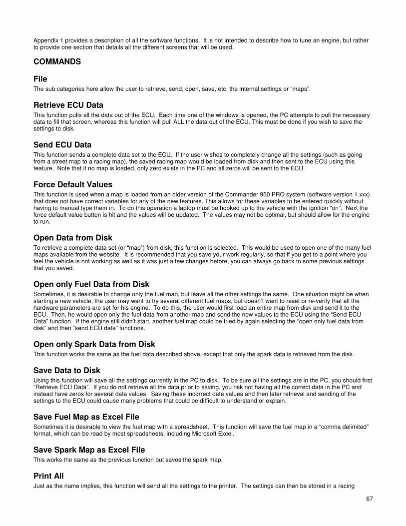
67
Appendix 1 provides a description of all the software functions. It is not intended to describe how to tune an engine, but rather to provide one section that details all the different screens that will be used.
COMMANDS
File The sub categories here allow the user to retrieve, send, open, save, etc. the internal settings or “maps”.
Retrieve ECU Data This function pulls all the data out of the ECU. Each time one of the windows is opened, the PC attempts to pull the necessary data to fill that screen, whereas this function will pull ALL the data out of the ECU. This must be done if you wish to save the settings to disk.
Send ECU Data This function sends a complete data set to the ECU. If the user wishes to completely change all the settings (such as going from a street map to a racing map), the saved racing map would be loaded from disk and then sent to the ECU using this feature. Note that if no map is loaded, only zero exists in the PC and all zeros will be sent to the ECU.
Force Default Values This function is used when a map is loaded from an older version of the Commander 950 PRO system (software version 1.xxx) that does not have correct variables for any of the new features. This allows for these variables to be entered quickly without having to manual type them in. To do this operation a laptop must be hooked up to the vehicle with the ignition “on”. Next the force default value button is hit and the values will be updated. The values may not be optimal, but should allow for the engine to run.
Open Data from Disk To retrieve a complete data set (or “map”) from disk, this function is selected. This would be used to open one of the many fuel maps available from the website. It is recommended that you save your work regularly, so that if you get to a point where you feel the vehicle is not working as well as it was just a few changes before, you can always go back to some previous settings that you saved.
Open only Fuel Data from Disk Sometimes, it is desirable to change only the fuel map, but leave all the other settings the same. One situation might be when starting a new vehicle, the user may want to try several different fuel maps, but doesn’t want to reset or re-verify that all the hardware parameters are set for his engine. To do this, the user would first load an entire map from disk and send it to the ECU. Then, he would open only the fuel data from another map and send the new values to the ECU using the “Send ECU Data” function. If the engine still didn’t start, another fuel map could be tried by again selecting the “open only fuel data from disk” and then “send ECU data” functions.
Open only Spark Data from Disk This function works the same as the fuel data described above, except that only the spark data is retrieved from the disk.
Save Data to Disk Using this function will save all the settings currently in the PC to disk. To be sure all the settings are in the PC, you should first “Retrieve ECU Data”. If you do not retrieve all the data prior to saving, you risk not having all the correct data in the PC and instead have zeros for several data values. Saving these incorrect data values and then later retrieval and sending of the settings to the ECU could cause many problems that could be difficult to understand or explain.
Save Fuel Map as Excel File Sometimes it is desirable to view the fuel map with a spreadsheet. This function will save the fuel map in a “comma delimited” format, which can be read by most spreadsheets, including Microsoft Excel.
Save Spark Map as Excel File This works the same as the previous function but saves the spark map.
Print All Just as the name implies, this function will send all the settings to the printer. The settings can then be stored in a racing

68 68
logbook, for example.
Password
Figure 47
The software package allows password protection, if so enabled. This window is used to set/reset the password and for password verification once set. If the password is not set, the window will come up as shown and allow the user to set the new password. Type the password in the text space available and press Set Password. Once the password is set, the password protection can be enabled by checking the checkbox labeled “Password Protection On”. Once the password protection is enabled, the unit will need to have the password sent before any values can be viewed or changed. If you forget to send the password and go straight to a tuning screen, only zeros will be displayed. If new values are sent, they will not be accepted by the ECU, until after the password is sent and verified. Once the password is verified by the ECU, normal communication will resume. DON’T FORGET YOUR PASSWORD. IF YOU FORGET IT, YOU MUST SEND THE ECU BACK TO HOLLEY TO HAVE THE PASSWORD CLEARED.
Exit Use this to exit the software.
Comm Under this heading, the user must select the serial communication port (“Comm Port”) that will be used to communicate with the ECU. The software must know where to look for the ECU and supports comm ports one through four. If your computer does not have a DB9 serial port (many newer laptops don’t), you will need to purchase a USB to DB9 serial adapter from your local computer store. Once the selection is made, the software will “remember” the settings the next time you use it.
FUEL These allow the user to alter the fuel specific parameters of the engine.
Main Fuel Map This is the primary table the engine uses when it is running. Each box or “cell” contains a number representing the injector pulse time. The larger the number, the longer the injector is pulsed, and the more fuel is delivered. The cells are organized by engine speed (RPM) and load (MAP or TPS depending on whether speed-density or Alpha-N is selected; typically, speed-density will be used). Typically, the greater the manifold pressure, the more fuel is needed. Also, the fuel requirements vary with engine speed based on the breathing efficiency of the engine. If the ECU is attached to the PC, the cell background color will change to indicate which cell is being utilized by the ECU for its fuel calculations. This cell background color change will move around as the engine speed and load change.
When first brought up, the cursor will be in the lower left corner of the cells. Obviously, you can use the mouse to move the cursor to different cells, but it is probably more beneficial to use the arrow keys. When using the arrow keys, the number in the cell will be highlighted so you can immediately type a new number to alter the fuel amount in that cell. You can also use the up and down arrow keys with the shift or control keys pressed to increase the cell value. After using the arrow keys to change the cell value or typing a new number, the data is not sent to the ECU until you press enter or move off that cell with the arrow keys. All other cells in the system work the same way. Pressing ctrl-R will fill all cells in the row to the right of the cell you are working on with the same value you just entered. This can greatly speed up the process of building a map from scratch.
Another feature is the use of the “Cell action” function. If you click on one cell and click on another cell, the square they create will be highlighted yellow and a “Cell Action” window will appear. You can now type either +, -, *, /, =, or % followed by a number and that action will be performed. For example, if you type “*1.5”, all the highlighted cells will be multiplied by 1.5 and the new values will be sent to the Commander 950 PRO. If the “=” sign is used, a single number can be entered in all selected cells. For example “=20” would put a 20 in all selected cells.
A very useful feature that is provided in the fuel map is that if a number is entered that will cause the injectors to become static, that cell will be highlighted in red. This means that increasing this number further will not add any additional fuel to the engine.

69
Figure 48
Data Monitor Used for monitoring real-time engine parameters.
Both the Main Fuel Map and Spark Map screens have a readout of real-time engine parameters above the graph. This is an essential tool when tuning an engine. The following is an explanation of each readout:
Closed Loop Compensation – Indicates the percent modification to the base fuel injection pulse width, only when the engine is operating closed loop. 100 would mean that no correction is occurring. 120 would mean that the computer is adding 20% more fuel to the base pulse width value. A value of 80 would mean that the computer is subtracting 20% from the base pulse width.
Closed Loop Compensation Graph – There is a small bar graph that is a graphical representation of whether the computer is adding or subtracting fuel in a closed loop mode. If the bar graph reads to the right, the computer is adding fuel because the base pulse width is leaner than the target air fuel ratio. If the bar graph reads to the left, the computer is subtracting fuel because the base pulse width is rich. The far left or right of the scale indicates a fuel change of 10% at least.
Rich/Lean Indicator Light – This light includes the voltage output from the oxygen sensor in large numbers to aid in tuning. When the air/fuel ratio is leaner than 14.7:1, it will turn red. When the air/fuel ratio is richer than 14.7:1, it will turn yellow. When the voltage is higher than .75V, it will turn green. This signifies a safe air/fuel ratio under load. The colors will only change when a narrow-band oxygen sensor is used. The background will not change when a wide-band sensor is used.
RPM – Indicates actual engine speed. This new software shows the engine speed to one RPM.
Spk Adv – Shows current spark advance.
IAC Position – Indicates the position of the pintle on the idle air control motor. This is a very important reading for adjusting idle. The scale reads from 0 (closed) to 200 (fully open). If the idle is too high and this value is 10, the IAC can not close further, which means that the throttle plates must be closed instead. If the idle is too low and the value is 200, the IAC is fully open and can not add more air, which means that the throttle plates must be opened more.
O2 Trigger Voltage/Target A/F – When a narrow-band oxygen sensor is used, this Indicates the voltage level the ECU is trying to maintain at the O2 sensor input. When a wide-band oxygen sensor is used, this indicates the air/fuel ratio the ECU is trying to maintain.
MAP – Shows the manifold pressure: if 1 bar, will vary between 0-100, 2 bar=0-200, and 3 bar=0-300.

70 70
TPS – Shows the position of the throttle position sensor. MAT – Manifold air temperature in degrees Fahrenheit.
O2 – Shows the output voltage from the oxygen sensor. The range is 0 to 1 volt for a narrow-band oxygen sensor and 0-5 volts for most wide-band oxygen sensor inputs.
V Bat – Indicates battery voltage.
Coolant – Indicates the coolant temperature in degrees Fahrenheit.
MAT Mod – Indicates the modification to the base fuel pulse width based on intake air temperature. Based off of a percentage of 100%.
Clt Mod – Indicates the modification to the base fuel pulse width based on coolant temperature. Based off of a percentage of 100%.
Aft Mod – Indicates the fuel afterstart modifier—percentage based.
Atm Mod – Indicates modification due to atmospheric conditions—percentage based. This modifier is now always available (old software made it available in Alpha-N mode only.)
Inj PW – Indicates fuel injector pulse width. Units are milliseconds.
Duty Cycle – Indicates the amount of time that the injectors are open, based on a percentage of available on and off time. It is important to make sure it is not over 85% (ideally) at wide-open throttle. This will reduce injector overheating. If it is 100 or more, the injectors are fully open (static) and can not provide any more fuel to the engine. If you enter a value in the injection volume table that will drive the system to a static condition, that cell will become red. This value will have to be lowered. If more fuel is needed, the fuel pressure can be raised, or larger injectors are needed. Labels on the left indicate status of various functions by changing the background color. For example, you will notice that the “Fuel Pump On” will highlight when the fuel pump is running.
Trigger Type – Indicates the ignition type selected in the engine parameters.
Fuel Graph This is a graphical representation of the fuel cell values. When properly tuned, the fuel map should be smooth. The graph mode can be used to refine the fuel values into a smoother curve. You will want to view some of the supplied fuel maps to see what a fuel graph should look like once finished. Once you become familiar with engine tuning, you can often tune an engine very close by tuning 10 to 15 points and using the fuel graph feature to fill in the rest. You can move around this map using the arrow keys and can alter values by pressing the shift or ctrl key along with the up or down arrow. Naturally, the up arrow increments the values and the down key decrements the values. The shift key causes the step amount to be one unit, whereas using the ctrl key causes the changes to be made by 5 units. After making changes, the new value is not sent, until you press “Enter” or move off the cell using one of the arrow keys.
Figure 49
Startup Enrichment The following five parameters are used by the ECU during cranking and shortly after the engine actually starts.
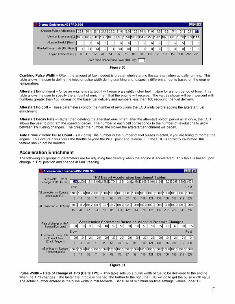
71
Figure 50
Cranking Pulse Width – Often, the amount of fuel needed is greater when starting the car than when actually running. This table allows the user to define the injector pulse width during cranking and to specify different amounts based on the engine temperature. Afterstart Enrichment – Once an engine is started, it will require a slightly richer fuel mixture for a short period of time. This table allows the user to specify the amount of enrichment that the engine will receive. The values shown will be in percent with numbers greater than 100 increasing the base fuel delivery and numbers less than 100 reducing the fuel delivery. Afterstart Holdoff – These parameters control the number of revolutions the ECU waits before adding the afterstart fuel enrichment. Afterstart Decay Rate – Rather than deleting the afterstart enrichment after the afterstart holdoff period all at once, the ECU allows the user to program the speed of decay. The number in each cell corresponds to the number of revolutions to allow between 1% fueling changes. The greater the number, the slower the afterstart enrichment will decay. Auto Prime 7 mSec Pulse Count – (TBI only) This number is the number of fuel pulses injected, if you are trying to “prime” the engine. This occurs if you press the throttle beyond the WOT point and release it. If the ECU is correctly calibrated, this feature should not be needed.
Acceleration Enrichment The following six groups of parameters are for adjusting fuel delivery when the engine is accelerated. This table is based upon change in TPS position and change in MAP reading.
Figure 51
Pulse Width – Rate of change of TPS (Delta TPS) – This table sets up a pulse width of fuel to be delivered to the engine when the TPS changes. The faster the throttle is opened, the further to the right the ECU will go to get the pulse width value. The actual number entered is the pulse width in milliseconds. Because of minimum on-time settings, values under 1.5

72 72
milliseconds will not inject fuel.
AE Correction vs. Coolant Temperature (%)– This allows the user to give more acceleration fuel based on the engine temperature to compensate for fuel droplets sticking to the manifold walls or cylinder walls. The number entered is a percentage modification to the Delta TPS. Numbers over 100, such as 110 (%), add 10 percent more fuel to the base Delta TPS number. Numbers lower than 100, such as 90 (%), reduce the base Delta TPS by 10 percent. If 100 is entered, there is no modification due to temperature to the base Delta TPS. AE Correction vs. TPS (%)– This allows the user to adjust the size of the acceleration compensation, based on how far open the throttle is. This can be very useful for large throttle bodies, where small changes off idle can give large airflow increases. Changes to the throttle after about mid-throttle give little airflow increase. This is also percentage-based with numbers lower than 100 subtracting a percentage from the base Delta TPS and numbers higher than 100 adding a percentage to the base Delta TPS. The numbers below the table indicate the throttle position sensor position. Rate of Change of MAP Sensor (Delta MAP) – A change in the manifold pressure can indicate a change in the engine loading requirements. The values entered are fuel units, are the same as the base fuel map (whole numbers), and are added to the base fuel value. Decay – This is how fast to pull out the additional fuel after detecting a change in the manifold pressure. This is the number of triggers to wait between the subtraction of 1% of enrichment. AE of MAP vs. Coolant Temperature (%) – Colder engine temperatures may require different transitional fueling requirements. This table allows the user to tailor the synchronous fueling to the engine temperature. Numbers are percentage-based. Numbers below 100 subtract a percentage from the base Delta MAP and numbers higher than 100 add a percentage to the base Delta MAP.
Modifiers The following three tables adjust the base fuel delivery according to various external sensors. All table entries are in percent. Numbers greater than 100 increase the fuel delivered, and values lower than 100 decrease the amount of fuel delivered.
Figure 52
Air Temperature Enrichment (%) – This table adjusts the base fuel delivery based on the air temperature. The density of air increases one percent for every eleven degrees Fahrenheit of temperature increase. Once the engine is tuned correctly at a certain temperature, the fuel should be adjusted accordingly for all temperatures warmer and colder than the tuning air temperature.
Coolant Temperature Enrichment (%)– This table is similar to a carburetor’s choke function. At cold engine temperatures, the engine will need more fuel, because some of the injected fuel will stick to the manifold walls or to the walls of the cylinder. At higher engine temperatures, this table can be used to increase the amount of fuel delivered to help cool the engine down.
Additional Timing vs. Temperature (degrees)– This table allows the tuner to add or subtract ignition timing, based on the current engine temperature. This could be useful to add a little timing when the engine is cold to help increase the idle or to get a little more power out of the engine when the cooler engine temperatures permit. A zero value will not change the timing at all. Values greater than zero increase the timing and values less than zero decrease the timing.
Barometric Compensation (%) – This table is available in just Alpha-N mode. It allows the user to adjust fuel delivery as altitude changes. As shown in Figure 52, one of the cells will be highlighted that will correspond to the barometric pressure being used. A value of 100 in this cell will not change the programmed fuel delivery amount. A value greater than 100 will increase the amount of fuel to be delivered and an amount less than 100 will decrease the amount of fuel delivered. If this feature is to be used, do all the fuel tuning at a constant altitude. Once the fuel map is tuned, adjust the barometric

73
compensation values to adjust for altitude requirements. In order for this to work properly, the map sensor must be open to atmospheric air.
SPARK These are all the parameters for adjusting the spark delivery to the engine.
Main Spark Map This is the primary spark map used by the ECU to determine where to make the spark. The table is organized just like the fuel map, where moving further to the right represents an increase in the engine speed and traveling up the table represents an increase in the engine load. The number in each cell represents the actual timing degrees for the engine. If the ECU is attached to the PC, the cell background color will change to indicate which cell is being utilized by the ECU for its spark calculations. This cell background color change will move around as the engine speed and load change, just as in the fuel map. The spark map also has most of the data monitor features of the fuel map. The spark map has the same feature as the fuel map, whereby large changes can be made by selecting an area of cells and performing a mathematical function to them (+,-,/,*,=).
Figure 53
Main Spark Graph This is a graphical representation of the main spark map. You will want to view some of the supplied spark maps to see what a spark graph should look like once finished. You can move around this map using the arrow keys and can alter values by pressing the shift or ctrl key along with the up or down arrow. Naturally, the up arrow increments the values and the down key
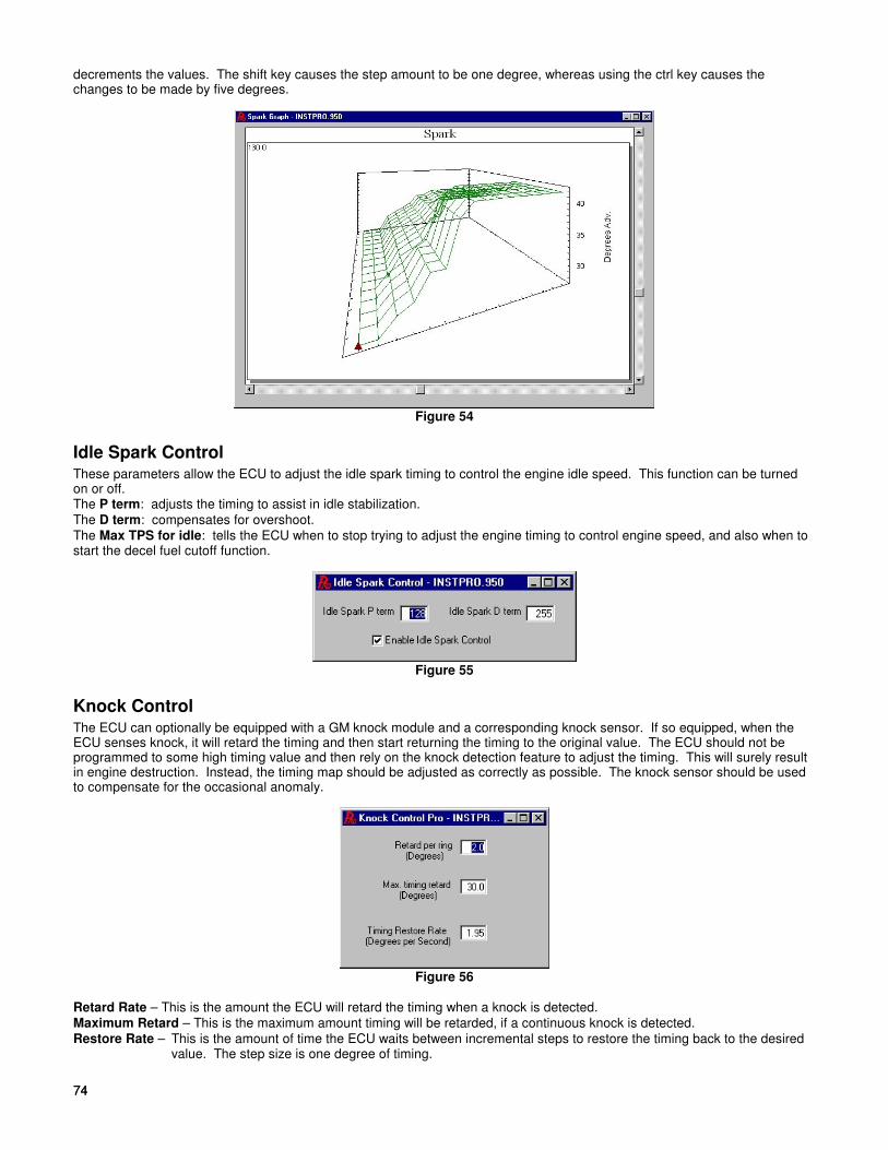
74 74
decrements the values. The shift key causes the step amount to be one degree, whereas using the ctrl key causes the changes to be made by five degrees.
Figure 54
Idle Spark Control These parameters allow the ECU to adjust the idle spark timing to control the engine idle speed. This function can be turned on or off. The P term: adjusts the timing to assist in idle stabilization.
The D term: compensates for overshoot.
The Max TPS for idle: tells the ECU when to stop trying to adjust the engine timing to control engine speed, and also when to start the decel fuel cutoff function.
Figure 55
Knock Control The ECU can optionally be equipped with a GM knock module and a corresponding knock sensor. If so equipped, when the ECU senses knock, it will retard the timing and then start returning the timing to the original value. The ECU should not be programmed to some high timing value and then rely on the knock detection feature to adjust the timing. This will surely result in engine destruction. Instead, the timing map should be adjusted as correctly as possible. The knock sensor should be used to compensate for the occasional anomaly.
Figure 56
Retard Rate – This is the amount the ECU will retard the timing when a knock is detected.
Maximum Retard – This is the maximum amount timing will be retarded, if a continuous knock is detected.
Restore Rate – This is the amount of time the ECU waits between incremental steps to restore the timing back to the desired value. The step size is one degree of timing.
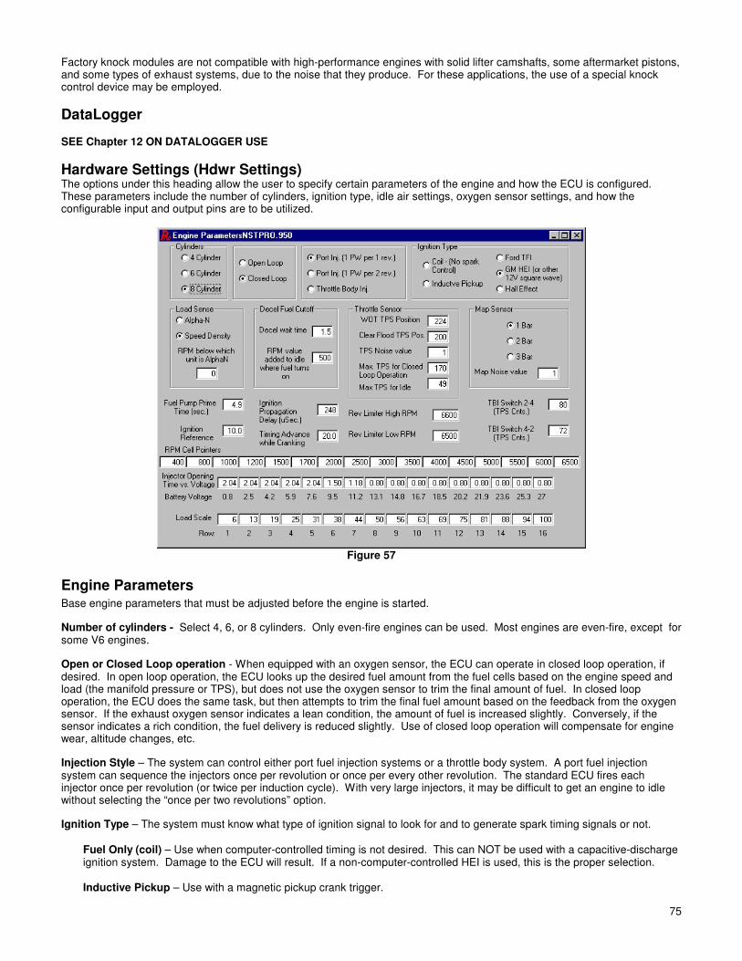
75
Factory knock modules are not compatible with high-performance engines with solid lifter camshafts, some aftermarket pistons, and some types of exhaust systems, due to the noise that they produce. For these applications, the use of a special knock control device may be employed.
DataLogger SEE Chapter 12 ON DATALOGGER USE
Hardware Settings (Hdwr Settings) The options under this heading allow the user to specify certain parameters of the engine and how the ECU is configured. These parameters include the number of cylinders, ignition type, idle air settings, oxygen sensor settings, and how the configurable input and output pins are to be utilized.
Figure 57
Engine Parameters Base engine parameters that must be adjusted before the engine is started.
Number of cylinders - Select 4, 6, or 8 cylinders. Only even-fire engines can be used. Most engines are even-fire, except for some V6 engines.
Open or Closed Loop operation - When equipped with an oxygen sensor, the ECU can operate in closed loop operation, if desired. In open loop operation, the ECU looks up the desired fuel amount from the fuel cells based on the engine speed and load (the manifold pressure or TPS), but does not use the oxygen sensor to trim the final amount of fuel. In closed loop operation, the ECU does the same task, but then attempts to trim the final fuel amount based on the feedback from the oxygen sensor. If the exhaust oxygen sensor indicates a lean condition, the amount of fuel is increased slightly. Conversely, if the sensor indicates a rich condition, the fuel delivery is reduced slightly. Use of closed loop operation will compensate for engine wear, altitude changes, etc.
Injection Style – The system can control either port fuel injection systems or a throttle body system. A port fuel injection system can sequence the injectors once per revolution or once per every other revolution. The standard ECU fires each injector once per revolution (or twice per induction cycle). With very large injectors, it may be difficult to get an engine to idle without selecting the “once per two revolutions” option.
Ignition Type – The system must know what type of ignition signal to look for and to generate spark timing signals or not.
Fuel Only (coil) – Use when computer-controlled timing is not desired. This can NOT be used with a capacitive-discharge ignition system. Damage to the ECU will result. If a non-computer-controlled HEI is used, this is the proper selection.
Inductive Pickup – Use with a magnetic pickup crank trigger.

76 76
Ford TFI – Use with Ford TFI electronic distributors. This allows for the Commander 950 PRO to control ignition timing. This requires an adapter cable PN 534-139, which is included in Ford 5.0L MPFI kits.
GM HEI – If any of the following ignition systems are used, select GM HEI. - 1981 and up GM small and large cap computer-controlled HEI distributors. This allows for the Comm 950 PRO to
control timing. Adapter PN 534-138 is needed with small cap distributors. It is included with all Holley small and big block Chevy MPFI systems.
- CD ignition system with a fixed timing (typical with race applications) point (for example 36°) when the tach output from the CD ignition system will be used to trigger the fuel system.
Hall Effect – Use with a Hall Effect crank trigger of Hall Effect Distributor. Load Sense – The ECU can operate in either Alpha-N or Speed-Density mode. Speed density is always used if possible, but for applications with low manifold vacuum, Alpha-N is most likely needed. As an alternative to selecting Alpha-N, an RPM can be selected where the ECU will switch from Speed Density to Alpha-N. Using this feature, a person could have a radical cam and operate in speed density during all but idle conditions, where it would use the TPS position to determine fuel requirements. For example, if the engine is equipped with a radical cam, which will not generate any significant vacuum below 1500 rpm, a value of 1500 could be entered into the rpm transition cell. If the vacuum is above 1500, the system would operate in speed density mode. If the vacuum is below 1500, the system would operate in Alpha-N mode. If this feature is not desirable, enter 0 for the minimum RPM Decel Cutoff – The Commander 950 PRO can cut fuel entirely when the system is in a deceleration mode. If the driver is cruising and removes his foot from the accelerator, so the TPS returns to the idle setting, the ECU will wait a programmable amount of time. If the RPM is high enough, the fuel will be cut. Fuel will be restored, if the TPS is moved above the idle setting or the engine speed approaches the idle setpoint. So as not to cut the fuel when shifting gears on a manual transmission, there is a programmable wait time. This time is typically set to about 1.5 seconds. When the fuel is shut off, the engine RPM will drop faster and the engine needs some time to react to the new fuel, once it is turned back on. For this reason, the fuel should be turned back on before the engine rpm reaches the desired idle rpm. The RPM parameter indicates how many rpm above the desired idle the fuel should be turned back on. As the desired idle speed changes, so does the setpoint, but it always stays the specified RPM above the desired idle. This parameter is usually set to about 300 RPM. Throttle Sensor – Adjust the following settings - WOT TPS Position – Enter the position of the TPS at wide-open throttle. Do this with the key “on” and engine not running.
Look at the data monitor in the main fuel map for this value. Reset, if the throttle position is changed at idle. - Clear Flood TPS Position – At a TPS position higher than this value, the ECU will not add cranking fuel. Make this number
about 50 lower than the WOT TPS Position. If the engine is flooded when it is started, depress the pedal past the Clear Flood TPS Position.
- TPS Noise Value – This value corresponds to how much of a throttle change needs to be made before the ECU detects it as having changed, and not just electrical “noise” having caused a sensor change. Numbers of 1 or 2 should be fine.
- Max TPS for Closed Loop Operation – This setting is where the system changes from closed to open loop. - Max TPS for Idle – This value is important and should be set 5 numbers higher than the idle TPS position. Map Sensor – The ECU can be connected to a 1, 2, or 3 bar manifold pressure sensor. All naturally-aspirated applications will use a 1 bar MAP sensor. The 2 and 3 bar map sensors would be used in supercharged or turbocharged applications where a two bar sensor is good for up to 15 pounds of boost and a 3 bar sensor is good for up to 30 pounds of boost. Map Noise value – This value is very similar to the TPS noise value, except that it corresponds to the manifold pressure sensor instead of the throttle sensor. The base value of 3 should work fine. It should be set between 1 and 3. Fuel pump prime time – When the key is first turned to the on position, the system will energize the fuel pump to pressurize the system. The ECU will not allow the pump to run longer than this much time, if the engine is not started. Naturally, as soon as the engine is started, the fuel pump will turn on and remain on, until the triggers stop. This number can be raised if the fuel system takes an abnormally long time to prime. 5 seconds should be adequate. Ignition Reference – This angle corresponds to the position of the ignition-triggering device in crankshaft degrees. The following are guidelines for different ignition systems: GM HEI – Set to 10 Ford TFI – Set to 10 Crank Trigger and Hall Effect – Set 10 HIGHER than the maximum timing. For example, if you will have a maximum timing of 42 degrees, set the Ignition Reference to 52 and align the crank sensor with the magnet at 52 degrees before top dead center.

77
Ignition propagation delay – All ignition modules have some amount of delay built in. This parameter will compensate for this delay. If this delay is not correct, the timing light will show a timing advance or retard with engine speed, even if the timing curve is “flat”. This value should be set so that the actual timing is correct at all RPMs. Usually the base value of 48 usec is fine. If the rpm is raised and the actual timing (as measured with a timing light) is less than the desired (as shown on the laptop), increase the propagation delay until the actual timing matches the desired. If the actual timing is more than the desired, decrease the propagation delay. Make changes in units of 20 usec. Timing advance while cranking – This is the amount of timing the ECU will give when the engine is trying to start. This is only active when the Inductive or Hall Effect Settings are used. If HEI or TFI is used, the timing during cranking will be the same as the base module timing below 400 rpm. Rev. limiter high RPM – At this rpm, the engine will stop injecting fuel to limit the speed of the engine in an attempt to protect the engine from self-destruction. Rev. limiter low RPM – Once the ECU has stopped injecting fuel because the rev. limiter has been hit, this is the rpm the engine will have to drop below before the ECU starts injecting fuel again. This value is usually set 100 to 500 rpm lower than the rev. limiter high rpm, depending on the desired effect. TBI Switch 2-4 – Allows the rear two injectors to be shut off with a TBI system. At this value, the ECU will then allow all four injectors to start firing instead of just the two primary injectors. This MUST be set properly if a progressive throttle body is used. The value should be 10-15 higher than when the secondary plates start to open. Check this for your application. It should also be used with a non-progressive TBI setup, so that the pulse width at idle is higher for best idle. TBI Switch 4-2 – This is used to switch from all four injectors firing, back to two. This value should be about 10 below the TBI Switch 2-4 value. RPM Cell Pointers – This table allows the user to define where the breakpoints will occur in the fuel and spark maps. This feature allows the user to define where the most resolution should occur. For any vehicle, the fuel map should most broadly cover the most typical operating range. Street-driven vehicles should have the scale set up so that the idle and cruise regions have adequate resolution. Injector opening times – All injectors will take a certain amount of time to open before any fuel starts coming out. The amount of time this takes is dependent on battery voltage. Unlike most other systems on the market, this ECU allows the user to specify the amount of time the injectors need at specific battery voltages. The base values are fine for the majority of users. Unless you are involved in professional racing and don’t run an alternator to ensure a constant voltage, changing these numbers is not needed. The standard software allows settings for both port and TBI injectors. The new software uses the same table for both style of injectors. Load Scale – Much like the RPM cell pointers can set the breakpoints on the lower (“X”) axis, this scale is used to set the breakpoints on the left (“Y”) axis. Most likely, not all of the fuel map would be used with the standard firmware. This firmware allows you to specify where you want the resolution to be. For example, if you are running a blower motor and only make 6 lbs. of boost, you do not need the additional 10 lbs. of boost capability available in the standard software. In this instance, you may want to evenly space your pressure steps so that all 16 spaces are filled, but the top cell shows only 6 lbs. of boost. Because the load scale entries are made in kPa, you will need to convert pounds of pressure to kPa. One pound of pressure is equal to about 6.8 kPa. This feature can also be used to evenly space the load scale when running in Alpha N mode. In this mode, the throttle position will determine which row the ECU uses for its calculations. The TPS can range from 0 to 255 units, but it is unlikely that any application would ever use the entire range. Instead, the tuner will want to set the bottom row a couple of units lower than the idle TPS setting and the top row to be a couple units higher than the WOT TPS setting (the TPS position can be viewed on either the Fuel map screen or the Spark map screen in the data monitor section). All the rows between the top and bottom will most likely need to be evenly spaced, but it may be desirable to have the bottom rows be more finely spaced, so you can get good resolution just off idle.
Idle Air Control These parameters adjust how the idle air motor is controlled.

78 78
Figure 58 - IAC at position 200 Figure 59 - IAC at position 10
NOTE: It is not recommended that the user change these values. However, if desired, these can be altered to improve idle
characteristics and reduce “hunting”.
PID Definitions (for Idle Air Control) P (Proportional Term)—The proportional term makes a change based on how far the engine is from the setpoint. For example, if the desired idle is 750, the IAC would move more if the actual engine speed was 600 than if it was 700. The size of the “P term” determines how far the IAC moves. I (Integral Term)—The “I Term” acts to eliminate the steady state error. It is the job of the “I term” to get the engine to idle at exactly 750 rpm (or whatever the setpoint is) and not at 740 or 760 rpm, for example. D (Derivative Term)—This term looks at where the engine is going and when it will be in a half of a second. It doesn’t look at where the engine is right now. For example, if the desired idle is 750 and the engine speed is 700, but it is rapidly approaching 750, the “D term” will try to close the IAC to slow the engine down and keep it from “overshooting” the setpoint.
Figure 60 - Idle Air Control
Desired Idle – The engine idle speed will be controlled by the ECU and can be changed at different temperatures. If the engine is cold, the idle speed will need to be higher than if the engine is warm. This is because the oil will be thick and the friction internal to the engine will be greater. IAC Parked position – After the ECU is told to shut off, it will command the IAC motor to this location. By having the IAC motor parked in a known location, it will enable easier starting and a better initial idle on the restart. Minimum IAC Position – This table allows the user to cause the IAC to “follow” the throttle position. As the throttle is opened, you want the IAC to open also. This is to keep the engine from stalling when the throttle is instantly released. The IAC will not close lower than the throttle follower position, so you will want to set the throttle follower at zero for the idle TPS position and quickly ramp the IAC open after that.
Closed Loop Parameters All parameters dealing with closed loop operation and the use of the oxygen sensor are found in this screen.

79
Figure 61 - Closed Loop Parameters
O2 Compensation Step Size – This table shows how much fuel the ECU will take out or add to the current volume on each step, attempting to bring the air/fuel ratio to ideal. The base settings that ramp from 1 to 3 as the rpm increases are ideal.
Seconds between O2 Compensation Step changes – This table sets the amount of time the processor waits before further adjusting the fueling amount. This is commonly referred to as the transport delay. After a fuel change is made, the new amount must travel to the cylinder on the intake stroke, be compressed, ignited by the spark, push the piston down, leave through the exhaust valve, travel down the exhaust tube, and be sensed by the O2 sensor. If the values in this table are too small, the ECU will not allow the new fueling changes enough time to be sensed by the O2 sensor and would then make changes based on old information, not new information. If the values are too big, the ECU will take too long to settle on a change. These values are based on the position of the O2 sensor in the exhaust. The base map values are close for sensors mounted in the collector. Sensors mounted closer can have the values reduced. See what works best for your application.
Target O2 Voltage/Target A/F Ratio – This table is programmable via a similar table as that described for the compensation limit. The fuel map is broken into sixteen evenly sized portions and each portion has its own programmable voltage where the ECU will try to maintain the air/fuel ratio for wide-band sensors (10:1-18:1 range) or sensor voltage value for narrow-band sensors (0-1 volt). Changing the values will effectively change the air/fuel ratio that the ECU tries to maintain. Wide-Band O2 – With standard O2 sensors, lower voltages indicate a lean condition and higher voltages indicate a rich condition. Typically, aftermarket wide-band sensor amplifiers show the opposite; low voltages are rich and high voltages are lean. If a wide-band sensor is installed, it usually necessary to check this box – refer to the voltage-to-A/F ratio chart supplied by the manufacturer. The Holley Wide-Band oxygen sensor requires this box to be checked.

80 80
Figure 62 - How the O2 Parameters Correspond to the Fuel Map
Air/Fuel Ratio vs. Voltage This chart is used to enter the input voltage vs. air/fuel ratio from a wide-band oxygen sensor controller such as the Holley unit or those offered from other companies. These controllers input a voltage signal to the ECU that directly corresponds to the actual air/fuel ratio. This allows for the Commander 950 PRO to show the actual air/fuel ratio and allows for the user to input the actual air fuel ratio for closed loop operation. When a base map is selected that is specifically for use with the Holley wide-band oxygen sensor, these parameters will automatically have the correct numbers entered. If one of these base maps is not used, enter the following numbers when using a Holley wide-band oxygen sensor and controller: A/F Ratio 10.00 11.00 11.50 12.00 12.50 13.00 13.50 14.00 14.25 14.50 14.75 15.00 Voltage .73 1.13 1.34 1.53 1.73 1.88 2.06 2.22 2.29 2.35 2.42 2.45 A/F Ratio 15.50 16.00 17.00 18.00 Voltage 2.54 2.57 2.72 2.82 Note that this provides the Commander 950 PRO with the actual output curve of the controller. This does not limit the

81
Commander 950 PRO from seeing or outputting air/fuel ratios other than those inputted. In other words you will still be able to read and enter an air/fuel ratio such as 12.78:1. The ECU will interpolate between these numbers. If you are using a wide-band sensor and controller other than the one supplied by Holley, you must enter the voltage vs. air/fuel calibration curve from it. WARNING! IT IS VERY IMPORTANT THAT THIS CURVE IS ENTERED PROPERLY. IF IT IS NOT, IT IS POSSIBLE TO
CAUSE SEVERE ENGINE DAMAGE. O2 Compensation Limit The O2 compensation limit is an important and helpful tuning tool. It limits the amount of fuel the ECU can add or subtract depending on engine RPM and load. The X axis indicates RPM points and the Y axis indicates load points based on the MAP sensor or TPS readings. It is normal to allow the ECU to add or subtract 15-20% under idle and light to moderate load conditions. If running closed loop at higher loads or WOT, it is a good idea to not let the ECU take out much or any fuel. If a problem occurs or the sensor is damaged, closed loop operation won’t allow for any fuel to be removed causing a possible lean condition. Cold Start Delay – It takes time for the wide-band sensor to come up to proper operating temperature. Until this occurs, the wide-band controller will not provide an output to the ECU. For the cold start delay it is a good idea to give the sensor at least 180 seconds to arrive at proper operating temperature. Hot Start Delay – It take less time for the sensor to come up to proper operating temperature on a hot restart. It is a good idea to enter a value of at least 45 seconds for the hot start delay. If either of these numbers are not high enough, the engine may go closed loop before the controller is outputting a proper signal. This will cause for the ECU to show and adjust to a lean condition that is not real. RPM to Enter Closed Loop - This is the RPM above which closed loop operation will occur. With a wide-band oxygen sensor this usually means anytime the engine is operating so values of 400-500 RPM are usually desired. If for some reason you want to just idle open loop then this value would be a number just above idle such as 1200 RPM. Below This RPM Go Closed Loop – This is the RPM that an engine will go back from closed to open loop. It is typically about 100 RPM less then the RPM to Enter Closed Loop. Minimum Engine Temp – The minimum temperature of the engine is set before the ECU enters closed loop operation. This value is typically set between 100 to 160°.
Input/Output These parameters determine how some of the input and output lines are controlled. Two inputs and two outputs can be programmed by the user to perform different functions. Also, the internal datalogger speed and data set size is programmed here.
Figure 63 – Input/Output Screen

82 82
Input 1 (12V activation – B8) This input is positioned in location B8 of the main ECU connector. This line is activated by a 12V input. This input can be selected for three uses. The first use is as an indication of whether or not the A/C was activated and therefore if the idle speed needs to be increased. It can be used to start the internal datalogger, or it can be used to activate a timing retard. If the retard option is selected, you will need to program the amount of retard desired. If it is used for the datalogger, it is best if a momentary switch is used, although the datalogger can be trigger by a 12v input that is left on.
Input 2 (GND activation – B10) This input is positioned in location B10 of the main ECU connector. This line is activated by a Ground input. This input can be selected for three uses. The first use is as an indication of when the vehicle is shifted out of park or neutral and into drive or reverse and therefore needing a little “kick” of the IAC to overcome the initial load increase. It can be used to start the internal datalogger, or it can be used to activate a timing retard. If the retard option is selected, you will need to program the amount of retard desired. If it is used for the datalogger, it is best if a momentary switch is used, although the datalogger can be trigger by a 12v input that is left on. Note that only one retard is available and if both inputs are selected to perform the retard function, there will not be a doubling of the retard amount. For example, if the retard is programmed for 5 degrees for both the B8 and B10 lines, activating either of the lines will give 5 degrees of retard and activating both of the lines will still only give 5 degrees of retard (not 10).
Output 1 (D9) This output is positioned in location D9 of the main ECU connector. This line will give a ground output when activated and can supply up to four amps of current. This output can be programmed to function as a RPM activated switch, a TPS position switch, or a MAP position switch. Some possible uses include a shift light or a wastegate.
Output 2 (C1) This output is positioned in location C1 of the main ECU connector and normally functions as a fan switch, turning the fan on at one temperature and off at another. Alternately it can be programmed to function as a RPM, TPS, or MAP position switch as described above. This output supplies a ground connection when activated and can supply up to four amps of current.
About This section allows the user to enter notes, look up the version of the firmware and software, and specify the type of user.
Figure 64
Notes This window allows the tuner to view or change notes about the current fuel map. If an ECU is attached, it will extract the notes from the ECU. Otherwise, it will show whatever notes may be in memory. These notes are also saved to disk when the data is saved.
Version This window indicates the current software version and (if an ECU is connected to the computer) will also show the current firmware (the firmware is the ECU internal software) version. The user can also specify the “advanced user” box, which allows some more advanced features to be displayed in some of the windows.
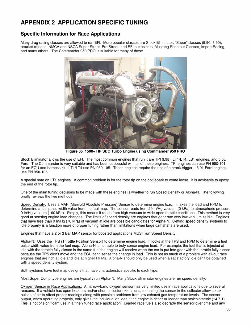
83
APPENDIX 2 APPLICATION SPECIFIC TUNING
Specific Information for Race Applications
Many drag racing classes are allowed to run EFI. More popular classes are Stock Eliminator, “Super” classes (9.90, 8.90), bracket classes, NMCA and NSCA Super Street, Pro Street, and EFI eliminators, Mustang Shootout Classes, Import Racing, and many others. The Commander 950 PRO is suitable for many of these.
Figure 65 1500+ HP SBC Turbo Engine using Commander 950 PRO
Stock Eliminator allows the use of EFI. The most common engines that run it are TPI (L98), LT1/LT4, LS1 engines, and 5.0L Ford. The Commander is very suitable and has been successful with all of these engines. TPI engines can use PN 950-101 for an ECU and harness kit. LT1/LT4 use PN 950-105. These engines require the use of a crank trigger. 5.0L Ford engines use PN 950-106.
A special note on LT1 engines. A common problem is for the rotor tip on the opti-spark to come loose. It is advisable to epoxy the end of the rotor tip.
One of the main tuning decisions to be made with these engines is whether to run Speed Density or Alpha-N. The following briefly reviews the two methods.
Speed Density: Uses a MAP (Manifold Absolute Pressure) Sensor to determine engine load. It takes the load and RPM to determine a fuel pulse width value from the fuel map. The sensor reads from 29 In/Hg vacuum (0 kPa) to atmospheric pressure 0 In/Hg vacuum (100 kPa). Simply, this means it reads from high vacuum to wide-open throttle conditions. This method is very good at sensing engine load changes. The limits of speed density are engines that generate very low vacuum at idle. Engines that have less than 9 In/Hg (70 kPa) of vacuum at idle are possible candidates for Alpha-N. Getting speed density systems to idle properly is a function more of proper tuning rather than limitations when large camshafts are used.
Engines that have a 2 or 3 Bar MAP sensor for boosted applications MUST run Speed Density.
Alpha-N: Uses the TPS (Throttle Position Sensor) to determine engine load. It looks at the TPS and RPM to determine a fuel pulse width value from the fuel map. Alpha-N is not able to truly sense engine load. For example, the fuel that is injected at idle with the throttle fully closed is the same fuel the engine will receive when the car is put into gear with the throttle fully closed because the TPS didn’t move and the ECU can’t sense the change in load. This is not as much of a problem with all-out race engines that are rich at idle and idle at higher RPMs. Alpha-N should only be used when a satisfactory idle can’t be obtained with a speed density system.
Both systems have fuel map designs that have characteristics specific to each type.
Most Super Comp type engines are typically run Alpha-N. Many Stock Eliminator engines are run speed density.
Oxygen Sensor in Race Applications: A narrow-band oxygen sensor has very limited use in race applications due to several reasons. If a vehicle has open headers and/or short collector extensions, mounting the sensor in the collector allows back pulses of air to affect proper readings along with possible problems from low exhaust gas temperature levels. The sensor output, when operating properly, only gives the individual an idea if the engine is richer or leaner than stoichiometric (14.7:1). This is not of significant use in a finely tuned race application. Leaded race fuels also degrade the sensor over time and any

84 84
readings it does emit have to be suspect over time. However, the output from it can be data-logged to give an idea if the fuel map might need to be changed as weather conditions change. For example, if it is reading .8 volts and drops to .75 volts when the air changes, it is a sign that the fuel map may need to be richened. For this reason it is HIGHLY recommended that a wide-band oxygen sensor be used in any race application. This makes tuning much easier. The air/fuel ratio can be datalogged and the fuel and timing tuned accordingly. Tuning a Race Engine: The best way to initially tune a high horsepower race engine is on the engine dyno. The dyno must provide certain feedback as to the brake specific fuel consumption (BSFC), and/or Air/Fuel Ratio to help initial tuning. Exhaust gas temperatures also provide helpful feedback. If the engine is already installed in the vehicle, a chassis dyno can be used for power measurement but is not near as useful as an engine dyno. High stall torque converters also makes tuning on the chassis dyno more complicated. Again, having a wide-band oxygen sensor makes tuning much easier. It is feasible to tune a high powered engine at the track safely using a wide-band oxygen sensor. Supercharged and Turbocharged Engines: Supercharged and turbo-charged engines must run speed density so that they can sense boost and the proper amount of fuel. A 2 or 3 bar MAP sensor needs to be used. A 2 bar sensor will register up to 14.7 psi of boost and a 3 bar will register up to 29.4 psi of boost. When you select 2 or 3 bar MAP sensor from the engine parameters screen, the manifold pressure scale on the fuel map will automatically change from 0 to 100 kPa to 0 to 200 kPa (2 bar) or 0 to 300 kPa (3 bar). This scale can and should be changed so that the highest value represents the most boost expected. This provides the maximum map resolution. The engine can still be precisely tuned, but the tuning must be more exact. Again, it is HIGHLY recommended to use a wide-band oxygen sensor on forced-induction engines.
TBI Specific Tuning Information TBI systems have some additional parameters that MUST be correct in order for the system to operate properly. Also included is some TBI specific tuning information that you will find helpful. TBI systems are inherently less efficient than Multi-port EFI systems. This shows up in the fuel required during cold engine operation and transient (when the engine speed changes) engine operation. The extra fuel required when the engine is cold (on a percentage basis) is higher with a TBI system than with a Multi-port system. The MAP based acceleration enrichment is usually higher than it would be with a Multi-port system. Base maps that are for TBI should have values that reflect this. Keep this in mind when you are tuning TBI systems.
Figure 66
1. Fuel Injection Type - In the engine parameter’s screen, Throttle Body Inj. must be selected for the fuel injection type.

85
2. TBI Switch – If a TBI system with progressive throttle linkage is used, the following two parameters must be set correctly or significant problems will occur. They also need to be adjusted with a non-progressive TBI system.
With a progressive linkage, the rear throttle plates do not open until the throttle is approximately 1/3 open. If the rear injectors are turned on before the rear plates start to open, the fuel would puddle on the throttle plates. The rear injectors need to be shut off until the rear throttle plates are open. The “TBI Switch 2-4” setting is the TPS position that the rear injectors turn on. To obtain the proper setting for this, turn the key on and with the engine not running open the throttle until the rear throttle plates just start to open. Note the TPS position. Add 10 to this number and enter it for the “TBI Switch 2-4” setting.
The “TBI Switch 4-2” is the TPS position that the rear injectors will turn back off when the throttle is closed. This value should be about 5 less than the “TBI Switch 2-4” setting.
Figure 67
3. Under “Fuel” and “Startup Enrichment”, you will find what is called “Auto Prime 7 Msec Pulse Count”. This feature allows you to add some fuel to wet the intake manifold before the engine is started. Most engines, when tuned properly, do not need to add this extra fuel. The key should just need to be turned and the engine should start. If this is not the case, the accelerator pedal can be pressed down with the key on and the engine not running, and the amount of fuel programmed into the area will be added. The value entered is the number of 7 millisecond pulses of fuel that will be added.
5.0L Ford Specific Tuning Information
5.0L Ford engines are typically more sensitive to idle tuning than most other engines. The following are some tips on tuning these engines.
1. When the engine is up to operating temperature and in neutral, make sure that the idle air control motor (IAC) is fully closed (signified by a position of 10). If the IAC is contributing to the air needed to idle when the engine is warm, it sometimes causes instability. To adjust this, very slowly open the throttle plates until the IAC is closed and you are at the desired idle speed. You may have to have the engine idle slightly higher than the desired idle speed to ensure the IAC does not open when the engine is in neutral.
2. Make sure you use the idle spark control feature.
3. Make sure the fuel map is smooth in the idle area. Make sure the timing map is “flat” in the idle area.
4. These engines typically like to idle at a leaner air/fuel mixture in order to idle smooth. Richer mixtures at idle sometimes make the engine surge. Try leaning the idle out if the engine surges.
5. The “P” term can be lowered in the Idle Air Control settings. This will slow the movement of the idle air control motor. Values as low as 3 to 5 are not uncommon. See what works best for your application.
APPENDIX 3 TUNING TROUBLESHOOTING Engine will not Start

86 86
There are several different reasons why an engine will not start. - Make sure that the engine is receiving a RPM signal. To verify this, see if the “Fuel Pump On” which is located on the data
monitor on the base fuel map screen, is highlighted in red (indicating the fuel pump is turned on). If it is not red, the ECU is not getting an RPM signal. There are several things to check, make sure everything is receiving power, as it should. Make sure that the proper ignition type is selected. Make sure all the ignition wiring is properly wired.
- If the ECU is receiving an RPM signal, it is most likely that there is not enough cranking fuel available. Go to the “Startup
Enrichment” screen and raise the “Cranking Pulse Width” at the proper temperature until the engine starts. Unstable Idle There are many things that can cause an unstable idle. The following are a list of possibilities. - Incorrect pulse width. If the engine is open loop and the mixture is too lean (as indicated by a low oxygen sensor voltage
output of 0 - .3 volts) the engine will tend to surge. If the engine is too rich (as indicated by a high oxygen sensor voltage output of .8 - .9 volts) the engine may load up and want to stall. Black smoke from the tailpipe is an obvious indicator of this. If the engine is running closed loop and the Closed Loop Compensation amount is at its maximum upper limit, the system is telling you that it is lean and that it can’t add enough fuel. The injection volume map needs to be increased. If the engine is running closed loop and the Closed Loop Compensation amount is at its lower limit, the system is telling you that the injection volume map is too rich and needs to be reduced at idle.
The fix for this is to alter the injection volume map.
- Oxygen sensor is too cool and causing incorrect closed loop feedback control (see Appendix 6). Generally the signs of this are when the system is running closed loop and adding fuel, yet the engine seems to be running to rich.
The fix for this is to move the oxygen sensor closer to the cylinder head. If this is not possible, the engine should be set to operate in open loop operation until it reaches an rpm where it has enough exhaust heat to function properly.
- Timing map is not “flat” in the area that the engine is idling at. While the engine is running, monitor the spark map. If the map is constructed in a way that the timing changes a lot at idle due to the map, the idle may not be smooth.
The fix is to modify the spark map so it is “flat” at idle.
- The throttle plates are too far closed. If the throttle plates are too far closed, the idle air motor must add a significant portion of the idle air. Generally, if the idle air motor shows a value of more than 30 in neutral at hot idle, the throttle plates should be opened more.
The fix is to open the throttle plates more.
- The fuel map is not smooth in the idle area. If the injection volume map has significant increases or decreases around the idle area, inconsistent fuel amount can be delivered to the engine causing an erratic idle.
The fix is to smooth the injection volume map in the idle area.
- Not enough spark advance. If computer controlled timing is used (which is highly recommended), the advance can be increased at idle which can stabilize the idle. Since the timing map is fully programmable, this has no affect on other areas of the timing such as wide-open throttle.
The fix is to increase only the idle spark timing.
- Engine too lean at idle when closed loop. Some engines require air/fuel ratios richer than stoichiometric (14.7:1) which
closed loop operation maintains. Typically engines with large camshafts and low manifold vacuum need to run richer than 14.7:1. If running a wide-band oxygen sensor, richen the target A/F table. If running a narrow-band oxygen sensor, raise the target O2 voltage at idle.
The fix is to change richen the target A/F ratio or O2 voltage.
Engine Hesitates When the Throttle is Applied
The following tuning will help alleviate hesitation when the throttle is applied. The flowchart (Figure 26) shows a graphical representation. - Injection volume map not correct. When the throttle is applied to accelerate, the areas on the injection volume map that
the ECU reads from changes (rpm and load increases). If the next area on the injection volume map that the ECU reads from is lean, a stumble will occur, even if there is a lot of acceleration enrichment.

87
The fix is to make sure that precise steady state mapping is performed at all points before transitional fueling and mapping is tuned.
- If steady state mapping is done, and there is a hesitation when the throttle is applied, than the “acceleration enrichment” under the “Fuel” column must be tuned. If there is a hesitation under a heavy load, increase the “Rate of Change of Map Sensor”. If the hesitation occurs when the engine is in neutral, increase the “Rate of Change of TPS”. Use a combination of the two for final tuning. The left portion of these tables is for slow changes in the TPS and the MAP sensors. The right portion of these tables is for fast changes in the TPS or MAP sensors.
The fix is to increase the Acceleration Enrichment Tables.
- Increasing or decreasing the timing can affect acceleration. Increase or decrease the timing at different points and feel the difference.
The fix is to modify the “Main Spark Map”
Cold Start Performance The following is tuning help for when the engine is cold. The following flowchart (Figure 68) provides a simple graphical representation.
Engine Runs Rough When Cold The following will help cold engine startup.
- If the engine runs poorly when it is cold, the problem could be that the base injection volume map is too lean. Before performing cold start tuning, make sure that the base fuel map is thoroughly tuned to be slightly rich of stoichiometric.
The fix is to tune the base fuel map after the engine is at operating temperature.
- After the base fuel map is tuned at operating temperature, if poor cold performance occurs, the coolant temperature enrichment most likely needs modifications. This can be tuned while the engine is running until it operates smoothly.
The fix is to add or subtract coolant temperature enrichment while the engine is running until it runs properly
Engine Stalls Immediately After Startup The following will help with problems after the vehicle is immediately started.
- If the engine stalls after it is started, the problem could be that the base fuel map is lean and/or the cold temperature enrichment is lean.
The fix is to properly map the base fuel map and the cold start enrichment. - If the base fuel map is correct, and cold temperature enrichment is correct and the engine still stalls after startup, the most
likely reason for this is that the afterstart enrichment is too low at the problematic temperature.
The fix is to increase the afterstart enrichment until the engine will remain running after startup.
- If the engine seems to struggle for air after startup, the “IAC Parked Position” most likely needs to be increased.
The fix is to increase the “IAC Parked Position”

88 88
GOOD! START THEENGINE THE NEXT
MORNING TORECHECK
SETTINGS**
DOES THE ENGINESTALL IN THE FIRST 2
SECONDS?
YES
INCREASEAFTERSTART
ENRICHMENT 5% ATTHAT ENGINE TEMP*
ADD 5% MORECOOLANT TEMPENRICHMENT AT
THAT ENGINE TEMP*
DOES THE ENGINESTALL DURING
WARMUP?
NO
NO
* The actual amount of fuelthatneeds to be added dependsuponhow far the settings areoff.
** The settings may needfinetuning as varying coldstartconditions change(summer towinter,etc.)
START THE ENGINE
YES
DOES THE ENGINERUN ROUGHLY DURING
WARMUP?
NO
ADD 2% MORECOOLANT TEMPENRICHMENT AT
THAT ENGINE TEMP*
YESDOES THE ENGINECONTINUE TO RUN
ROUGHLY?
NO
YES
Note: This flowchart is slightly simplified.Seeaccompanying text fordetails.
Figure 68 EFI Tuning Guide—Cold Start—After Base Map is Tuned Hot

89
APPENDIX 4 GENERAL TROUBLESHOOTING Double check ALL wiring connections and system voltages BEFORE replacing components. If you suspect an ECU or component failure, check all other possible problems before replacing a component.
CONDITION POSSIBLE CAUSE REMEDY
1. Fuel Pump fails to operate
- Open or blown fuse - Poor ground connection - Faulty power relay - Faulty fuel pump - Faulty ECU
- Replace fuse - Clean ground and tighten securely - See Testing Relay section - Check for voltage and ground at pump. If voltage and ground are present, replace pump. - Replace ECU
2. No fuel from injectors - Open or blown fuse - Poor ground connection - Injector connection loose - No fuel in tank - Low fuel pressure - High return fuel pressure - Bad fuel pump - No tach signal - Faulty ECU
- Replace fuse - Clean ground and tighten securely - Inspect and clean connections, reconnect - Add fuel to tank - Install pressure gauges and adjust pressure. - Kinked or restricted fuel line. Repair kinks and remove obstructions from lines - See Item 1 above - Make sure proper ignition signal wire is used - Replace ECU
3. Engine runs rich - High supply fuel pressure - High return fuel pressure - System not tuned properly - MAP sensor hooked up improperly - Faulty MAP sensor - Oxygen sensor mounted incorrectly - Faulty oxygen sensor
- Install pressure gauges and adjust pressure. - Kinked or restricted fuel line. Repair kinks and remove obstructions from lines - See Tuning section - Using vacuum gauge, ensure MAP sensor is hooked up to full manifold vacuum - See Testing MAP Sensor section - See Oxygen Sensor installation in instructions - Replace oxygen sensor
4. Engine runs lean - Low supply fuel pressure - System not tuned properly - Faulty MAP sensor - Faulty oxygen sensor - Incorrect system sizing
- Install pressure gauges and adjust pressure. - See Tuning section - See Testing MAP Sensor section - Replace oxygen sensor - See Choosing the Right System section
5. Hard starting (cold) - Faulty coolant temperature sensor - Faulty air charge temp sensor - Faulty IAC motor - Fuel pump not flowing fuel
- See Testing Coolant Temperature Sensor section - See Testing Air Charge Temp Sensor section - See Testing IAC section - See Item 1 above
6. Hard starting (warm) - Engine flooding - Faulty coolant temperature sensor - Faulty air charge temp sensor - Fuel pump not flowing fuel
- Use “Clear Flood” mode. Inspect injectors after shutting off engine for injector leakage. Replace leaking injectors. - See Testing Coolant Temperature Sensor - See Testing Air Charge Temperature Sensor - See Item 1 above
7. Poor performance - MAP sensor hooked up improperly - Faulty MAP sensor - Faulty coolant temperature sensor
- Using vacuum gauge, ensure MAP sensor is hooked up to full manifold vacuum - See Testing MAP Sensor section - See Testing Coolant Temperature Sensor section
8. High idle speed - Idle speed not adjusted correctly - Binding or sticking throttle linkage - Faulty IAC motor - Faulty ECU
- Set idle speed. - Find cause of binding or sticking and correct. - See Testing IAC section - Replace ECU
9. Low idle speed - Idle speed not adjusted correctly - Faulty IAC motor - Faulty ECU
- Set idle speed. - See Testing IAC section - Replace ECU
10. Surging idle - Engine running rich - Engine running lean - Idle fuel or timing not tuned correctly - Throttle plates not adjusting
- See Item 3 above - See Item 4 above. - See Tuning section - Adjust throttle plates

90 90
APPENDIX 5 TESTING AND TROUBLESHOOTING ELECTRICAL COMPONENTS
Testing Relays
1. To test the relays, apply a 12 volt power source to terminal 85 and ground terminal 86. The relay should click. Using an ohm meter, check for low resistance across terminals 87 and 30.
2. With the 12 volt power source removed from terminal 85, check for high resistance across terminals 87 and 30. 3. If the relay does not perform as described above, the relay is defective and must be replaced.
Testing the Manifold Absolute Pressure (MAP) Sensor (1 Bar)
One way to check the MAP sensor is to monitor the system with the software. Check the map sensor readings with the engine turned off. It should be fairly close to 101 kPa at sea level and decrease by about 3.4-3.5 kPa per 1000 feet elevation above sea level. The MAP value may also vary a small amount due to weather conditions. The table below shows MAP values in kPa compared to the more familiar units of in Hg. The second column is gauge pressure in Hg and the third column is vacuum in units of in Hg.
MAP Value to Manifold Pressure Value to Vacuum Comparison
MAP Value (as read on the computer) Manifold Pressure Value (in Hg) Vacuum (in Hg) Relative to Ambient Pressure Condition (sea level)
101 kPa 29.7 0.0 90 kPa 26.5 3.2 80 kPa 23.5 6.2 70 kPa 20.6 9.1 60 kPa 17.6 12.1 50 kPa 14.7 15.0 40 kPa 11.8 17.9 30 kPa 8.8 20.9 20 kPa 5.9 23.8
NOTE: Users at higher altitudes will have MAP values lower than 101 kPa as described in the above paragraph along with a lower corresponding manifold pressure. However, the vacuum on a typical vacuum gauge is referenced to ambient conditions and will read 0.0 with no engine vacuum regardless of MAP value unlike the sea level based third column in the above table. A MAP value lower than 20 kPa is most likely an indication of a bad MAP sensor connection or a MAP sensor problem.
1. If you do not have a PC, use a digital voltmeter and tap into the ORANGE wire at the MAP sensor. With the engine off and the key in the run position, voltage should be close to 5.0 volts.
2. Connect a hand vacuum pump to the MAP sensor with the key in the run position. Using the vacuum pump, the MAP
sensor can be checked at the following vacuums. Voltage output should be close to these values. The following values are for a 1 Bar MAP sensor.
20” Hg vacuum 1.1 volt 15” Hg vacuum 2.0 volt 10” Hg vacuum 2.8 volts 5” Hg vacuum 3.8 volts 0” Hg vacuum 4.6 volts at sea level (less at altitude)
Testing Throttle Position Sensor (TPS)
Test the sensor as follows:
1. Locate the harness wiring that connects to the TPS and remove a piece of the sheathing from the GREEN wire and the BLACK/WHITE wire.
2. Attach the (+) lead of the digital voltmeter to the GREEN wire (pin B) and the (-) lead to the BLACK/WHITE wire (pin A) of
the TPS. 3. Check the voltage on the TPS with the throttle closed. It should be between approximately .3 and .8 volts. While watching
the voltmeter, move the throttle lever from fully closed to fully open. The voltage should change smoothly from the idle voltage to 4.5-5.0 volts. If the reading fluctuates, the TPS is intermittent and should be replaced. If the voltage is range, turn the ignition key off, remove jumper wires, and reconnect the TPS.
91
4. Cover any exposed wiring with electrical tape to prevent shorting.
Testing Idle Air Control (IAC) Motor
A simple test for the IAC motor is as follows:
1. Remove the air cleaner assembly. Check the electrical connections at the IAC motor and at the ECU for integrity. 2. With the warm engine idling in neutral, place your finger slowly over the IAC opening. The idle speed should drop and the
suction on your finger will increase. 3. After 5 or 10 seconds, remove your finger from the opening. The engine idle speed should increase and then slowly return
to normal. 4. If your engine speed does not respond as described, the IAC motor is defective and must be replaced.
DANGER! ROTATING OR HOT PARTS IN AN ENGINE COMPARTMENT CAN CAUSE BURNS, SERIOUS INJURY AND/OR DEATH IF CONTACTED WITH A PERSON. KEEP LOOSE CLOTHING AND BODY PARTS AWAY FROM ROTATING OR HOT PARTS.
Testing Coolant Temperature Sensor
1. Remove the coolant temperature sensor from the manifold. Allow the sensor to reach room temperature, approximately
70° F. 2. With a digital voltmeter set to measure resistance and connected to the pins of the coolant temperature sensor, the
resistance should read approximately 3,800 Ω. 3. Place the sensor in boiling water with the voltmeter leads still connected. The resistance with the water boiling (212 F)
should be approximately 182 Ω. 4. If your coolant temperature sensor does not respond as described above, the sensor is defective and must be replaced.
Testing Air Charge Temperature Sensor
1. Connect a digital voltmeter set to read resistance to the air charge temperature sensor leads and not the resistance value. 2. Using a hair dryer, warm the tip of the air charge temperature sensor. The resistance should decrease as the tip is heated. 3. If your air charge temperature sensor does not respond as described above, the sensor is defective and must be replaced.
Testing the Oxygen Sensor (Narrow-Band only)
The COMMANDER 950 PRO systems oxygen sensor performance can be evaluated. The oxygen sensor voltage can be checked through the monitor option of the COMMANDER 950 PRO software. The other option if no PC is available is to probe the gray wire from the oxygen sensor connector with the positive (+) lead of a digital voltmeter. With the engine running open-loop, the meter reading should be near zero or one volt. During closed-loop operation, the readings should constantly change between zero and one volt. If the reading is always zero volts, be sure +12V and ground are present on the RED and BLACK wires. If so, the sensor is probably bad. If you see a changing voltage, but the readings do not vary far from 0.5 volts, the sensor is lazy and should be replaced. WARNING! Be sure to use a high impedance digital voltmeter. An older style analog (dial type readout) has an internal
resistance that is too low and will destroy the oxygen sensor if connected to the gray wire.

92 92
APPENDIX 6 OXYGEN SENSOR EFFECT ON PERFORMANCE
NOTE: The following is only for a NARROW-BAND oxygen sensor.
The oxygen sensor monitors the exhaust gases and outputs a voltage that corresponds to the air/fuel mixture. The range of voltage output from the oxygen sensor is 0.0 to 1.0 volts. A lean fuel/air mixture gives a lower oxygen sensor output voltage while a rich fuel/air mixture gives a higher oxygen sensor output voltage. The stoichiometric or chemically perfect fuel/air mixture gives an oxygen sensor output of approximately 0.5 volts. The engine ECU reads this output from the oxygen sensor and adjusts the fuel delivery to maintain a stoichiometric air/fuel mixture. Most automobiles, both currently and for the past 20 years, are using oxygen sensors to monitor the engine fuel/air mixture. This is done primarily to improve engine emissions. It also gives the advantage of maintaining a stoichiometric air/fuel mixture under varied operating conditions giving generally better engine performance and fuel economy.
Holley includes oxygen sensor feedback capability with the Commander 950 PRO system and recommends the user to use the oxygen sensor. For most user applications, better performance and fuel economy will be obtained by using the oxygen sensor. In addition, the oxygen sensor can make the tuning process much easier since the user can monitor the ECU functions as it adjusts the fuel to meet a stoichiometric fuel/air mixture.
The mounting location of the oxygen sensor is extremely important for the proper operation of the engine. The exhaust gas temperature (EGT) in the exhaust where the sensor is mounted is very important for proper closed loop operation. If the EGT is too low, two undesirable conditions can result. First, the ECU may sense that the O2 sensor is not up to proper temperature and will not activate closed loop operation. Second and much more troublesome is that the sensor could emit a false low voltage even if the air/fuel ratio is rich. The ECU will see this as a lean condition and add fuel to compensate in closed loop mode. This makes the rich condition even worse which will lower the EGT and complicate the problem. The lower the EGT the sensor sees, the slower the sensor will react, reducing the benefits of closed loop operation. The minimum recommended temperature for reasonable closed loop operation is 600° F (Fahrenheit) at the sensor. Maximum continuous temperature at the sensor is 1500° Fahrenheit. Most engines idle with an EGT of 800-1100° F near the cylinder head exhaust port. If the sensor is mounted far away, such as in the collector of long tube headers, the temperature may drop to as low as 300° F at idle. If the oxygen sensor attempts to control the air/fuel ratio when the EGT it sees is between 300 and 600° F, the problems mentioned above can occur.
It is recommended to mount the oxygen sensor as close as possible where one bank of cylinders merge together. If an OEM mounting location is available, use it. With stock cast iron manifolds, the sensor can be mounted in the exhaust pipe, right after the cast iron manifold in the exhaust pipe or possibly in the end of the manifold itself. If the vehicle has “shorty” headers, the sensor can be mounted in the collector of the headers. This is usually an acceptable location.
If the vehicle has long tube headers, the sensor can be mounted in the collector, but the temperature will likely be too low at idle for proper operation. A fix for this, if proper closed loop operation does not occur, is to run open loop at lower engine speeds until enough heat is available for proper operation. This is programmable in the ECU. Other factors such as camshaft specifications will effect how well closed loop operation occurs at low engine speeds and loads.
Figure 69
The oxygen sensor should be mounted in such a way the condensation in the exhaust tubing will not enter the sensor. Mount the O2 sensor in the upper half of the exhaust tubing, with the angle “x”, shown above (Figure 69), being greater than 10°. The picture above indicates that the sensor can be mounted on either side of the exhaust tubing. Figure 70 below shows the voltage output of an oxygen sensor. As shown, the voltage changes considerably when the air / fuel ratio approaches 14.7:1. This explains why a standard oxygen sensor is only accurate at signifying an air / fuel ratio of 14.7:1. Air / fuel ratios richer and leaner can only be approximated. As discussed above, if the exhaust gas temperature is too low, these readings will be false.

93
Figure 70 Narrow-Band O2 Sensor Voltage
The following information pertains to most WIDE-BAND oxygen sensors including the Holley Performance Products When installing most wide-band oxygen sensors, use figure 69 above for proper bung/sensor installation. Unlike a narrow-band sensor, a wide-band can and should be installed in the collector of an engine without worry. For a sensor to output properly, there should be at least 12-18 inches of pipe after the sensor, otherwise the exhaust will mix with outside air giving a false lean reading, especially at low RPM and load.
APPENDIX 7 DESCRIPTION OF FUEL INJECTION SYSTEMS
Combustion Principles and Air / Fuel Ratios During combustion of any substance a required surface to mass ratio and a correct amount of oxygen must be must be available. In internal combustion engines these requirements are controlled by the fuel management system. Optimum surface to mass ratio is achieved by finely atomizing the fuel, while the right air fuel ratio is achieved by metering fuel in proportion to the induced air. On a mass basis a mixture of 14.7 parts air and 1 part of fuel are required to sustain complete combustion. At ratios higher or lower than 14.7:1 combustion is still possible but it will not be complete. Mixtures that are either too rich or too lean will still burn but their combustion efficiency will be low generating unwanted by-products and other side effects. However, it is necessary to run at air/fuel ratios richer than 14.7:1 at high engine loads to avoid engine damage. This is due to the fact that complete and uniform atomization does not occur in reality, so extra fuel must be added to compensate. A rich mixture is characterized by a low air/fuel ratio: excess fuel and not enough oxygen present to support complete combustion. Very rich mixtures generate high hydrocarbon emissions and high carbon monoxide emissions. They also tend to reduce power and increase the carbon deposits, and in extreme cases, foul spark plugs and dilute engine’s lubricating oil. A lean mixture is characterized by a high air fuel ratio: excess air and not enough fuel to support a complete combustion. These mixtures burn slowly and high temperatures producing high NOx emissions. Fuel management systems can be calibrated to obtain maximum engine performance, best fuel economy, or lowest exhaust emissions. For maximum power the fuel management system is calibrated for a 12.6:1 air fuel ratio. Best fuel economy is attained at a 15.4:1 air fuel ratio. To meet today’s strict emission specifications the fuel management system must be able to maintain strict control of air fuel ratio in order to achieve the best compromise and meet the conflicting demands of maximum power and best fuel economy.
Fuel/Air Mixture Definition
Rich Stoichiometric Correct Mixture
Lean
Air/Fuel Ratio (A/F) 12.6 14.7 15.4
Lambda ( λλλλ ) 0.86 1.00 1.05
While air fuel ratio is a common way when referring to combustible mixtures, lambda is also used to determine the combustion efficiency. Lambda is the ratio of the air quantity supplied to the theoretical air quantity required for stoichiometric correct mixture. A stoichiometric correct mixture is equivalent to lambda equal to 1, a rich mixture is defined by lambda less than 1 and a lean mixture is defined by lambda larger than 1.
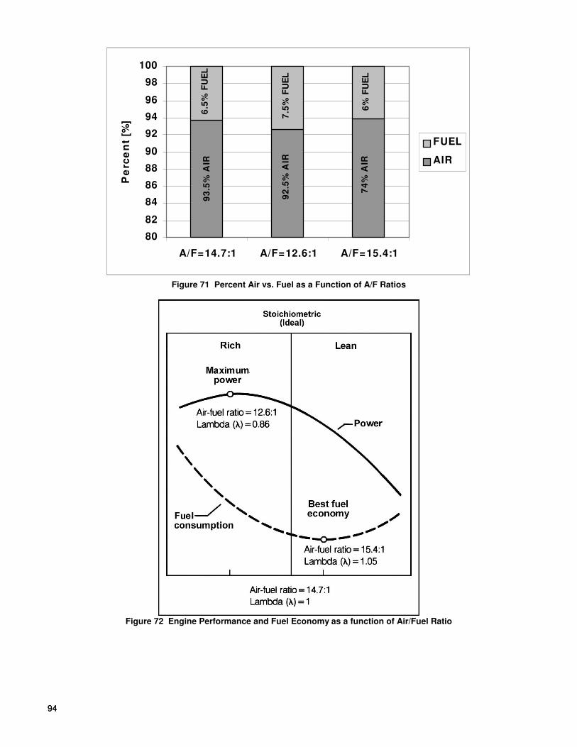
94 94
80
82
84
86
88
90
92
94
96
98
100
A/F=14.7:1 A/F=12.6:1 A/F=15.4:1
Pe
rce
nt
[%]
FUEL
AIR
93
.5%
AIR
6.5
% F
UE
L
7.5
% F
UE
L
6%
FU
EL
74
% A
IR
92
.5%
AIR
Figure 71 Percent Air vs. Fuel as a Function of A/F Ratios
Figure 72 Engine Performance and Fuel Economy as a function of Air/Fuel Ratio

95
Emissions and Performance
Internal combustion engines generate power by burning air and fuel mixtures. In gasoline fueled engines, the proportions of air and fuel (air/fuel ratio) are critical for optimum combustion. The quality of combustion is directly related to engine power output and its running characteristics. The goal of a fuel metering system is to generate a homogenous air/fuel mixture. A homogenous mixture of 14.7 parts of air and 1 part of fuel on a mass basis are required to achieve complete combustion. Homogenous mixtures are only possible when the fuel is totally vaporized. Vaporization can take place from the metering up to ignition process. To achieve maximum engine performance all cylinders should receive equal charges at a common air fuel ratio. Variations in quantity and air fuel ratios generate rough engine running conditions and detonation.
Deviation from stoichiometrically correct air fuel mixtures can generate excessive exhaust emissions, poor fuel economy, or poor engine performance. For stoichiometrically correct air fuel mixture 14.7 lb. of air per 1 part of fuel is required. For best engine performance a slightly richer mixture is required: 12.6 lb. of air per 1 lb. of fuel. Although this A/F ratio generates optimum engine performance it generates carbon monoxide emissions due to incomplete combustion. For best fuel economy a slightly leaner mixture is required: 15.4 lb. of air per 1 lb. of fuel. A 15.4 A/F ratio generates the lowest fuel consumption but affects engine driveability.
14.7: 1 + CO2 + H2O
12.6: 1 + CO2 + H2O + CO
15.4: 1 + CO2 + H2O + O2
Figure 73 Air / Fuel Ratio Effect on Emissions Output
Engine Management Systems
Three main functions are performed by the engine management system: air management, fuel management and ignition timing management.
Air Management
The mass flow rate of the induced air must first be determined to deliver the appropriate amount of fuel to an engine operating under certain conditions. The engine is like an air pump, with each intake stroke air is drawn into the cylinder. The piston moving down on its intake stroke increases the cylinder volume and lowers the cylinder pressure. With the intake valve open, air rushes in from the intake manifold to fill the cylinder and equalizes the differential pressure existent between the intake manifold and the cylinder.
The opening of the air valve regulates the pressure in the intake manifold. The greatest intake air flow occurs when the throttle valve is fully open and generates the highest intake manifold pressure. The least intake air flow occurs when the air valve is nearly closed. A closed throttle valve decreases the pressure in the intake manifold. Lower intake manifold pressure reduces the differential pressure between the intake and the cylinder directly reducing the airflow into the cylinders. The amount of fuel required to generate a stoichiometric mixture depends on how much air was induced into the cylinder.
There are 3 methods commonly used to determine the mass flow rate of air: speed density, air flow measurement and air mass measurement. In the speed density method the ECU calculates the induced amount of air based on the air inlet temperature, intake manifold pressure and engine RPM. The temperature and manifold pressure are required to calculate the density of the air and the RPM to calculate the flow.
In the air flow measurement approach the flow is measured using a vane type meter. The air density changes are compensated via an air inlet temperature sensor. In the air mass measurement method, the air charge is measured directly using a hot wire or hot film air mass flow sensor. The heated element is part of a bridge circuit that keeps the element at a constant temperature above the inlet air temperature.
The volumetric air flow rate is determined by the following general equation:
Volumetric Air Flow Rate = (RPM/60)*(Displacement/2)*Volumetric Efficiency
The volumetric efficiency is a ratio that describes how efficiently the engine acts as an air pump for its size. The volumetric efficiency is calculated by the following equation: Volumetric efficiency (VE) = Actual Volume of Air/Fuel induced into the Engine Engine Displacement

96 96
In general, the volumetric efficiency of naturally aspirated engine configuration is as follows:
Engine Configuration VE (%VE)
Stock Engine 0.85 85%
Modified Engine 0.93 93%
Highly Modified Engine 0.98 98%
Supercharged 1.0+ 100%+
Engine with VE above 100% are supercharged or turbo-charged applications. The supercharger or turbocharger is like a blower that pushes much more air into the engine than what could be drawn in naturally.
Fuel Management Fuel metering mainly comprises two tasks: metering of the fuel quantity in accordance with the required power output; control of the mixture composition in accordance with the air fuel ratio desired for a given engine load condition. The fuel metering function in spark ignited engines can be attained by two basic systems: carburetors or injection systems. Carburetors meter fuel by means of the Venturi principle. The air flow through the throats of the carburetor generate a vacuum (low pressure) which sucks the fuel from the float chamber via the metering jets. Larger flows of air through the carburetor increases the low pressure in the Venturi that in turn pulls more fuel through the metering jets. Fuel is therefore metered in proportion to the air flow. In electronic fuel injection systems, pressurized fuel is delivered in to the incoming air stream by means of an electrically actuated solenoid valve (fuel injector). The ECU determines the opening time of the injector to maintain the required air fuel ratio according to the air flow that is being measured or calculated. The longer the injector is open, the more fuel is injected. Because the fuel is delivered under pressure the fuel metering operation can be managed more precisely to meet the special engine operating demands. Fuel metering depends on how much load is applied to the engine. Driving uphill at constant speed would require a larger air valve opening than cruising on a level road. When opening the air valve the intake pressure rises causing more air to fill the cylinder, which in turn causes a higher supply of fuel, generating more power from the engine. Regardless of engine speed, the air flow and fuel delivery is directly proportional to the load applied on the engine. The load and the resulting air valve opening directly affects intake manifold pressure. In turn manifold pressure affects air flow and thus fuel requirements. In electronic fuel injection systems, also sometimes referred to pulsed systems, the fuel is metered in reference to a measured air flow by means of solenoid activated metering valves (injectors). The airflow is measured by a sensor, which generates an electronic signal proportional to the flow. The electronic control unit (ECU), responding to the airflow signal, meters fuel to the engine by means of the injectors. Fuel is metered in a series of short pulses, which are proportional to the engine RPM and load. The main components are: the fuel pump, which must deliver reliably, without pulsation in flow, at closely controlled pressure; the injectors, which must contribute to accurate metering, without pre- or post-injection dribble, and deliver the fuel in a highly atomized spray; and the electronic control unit. Sensitivity of the control unit to engine parameters and ambient conditions are essential. The sensors generating the required signals must therefore function reliably and accurately. There are two major multi-point fuel injection strategies that are currently being used in the automotive industry:
- Sequential Fuel Injection System. In this fuel management system each injector is controlled separately. The timing of the metering event, referenced both to the crankshaft/camshaft position and the pulse width can be optimized for each individual cylinder.
- Batch or Group Fuel Injection System. The injectors are divided into two or more groups that are activated separately. Each group meters fuel once per each cycle of a 4 stroke engine. Each group or pair of group is offset by one crankshaft revolution. This arrangement allows for an injector timing selection that eliminates metering the fuel into an open intake valve. Holley uses this type of system.
A subsystem of the fuel management system is the O2 or lambda closed loop control. Lambda defines the deviation from a stoichiometrically correct combustion: 14.7:1 air/fuel ratio (lambda =1.00). Under steady state conditions, the O2 sensor (lambda sensor) oscillates between rich and lean within a defined operating window. As the O2 sensor switches, the injector pulse width is adjusted by the ECU until the lambda sensor switches again to the opposite condition. This switching operation continuously supplies the ECU with the information needed to maintain a stoichiometrically correct combustion. Three wire O2 sensors are designed to indicate an air/fuel ratio of 14.7:1. Although the voltage output can be used to estimate the air/fuel ratio above and below this, it can only be used as an estimate.

97
Ignition Timing Management Two major ignition systems are available in the automotive industry: the mechanical system (including electronic ignition) and the microcomputer controlled ignition system. In a mechanical system timing advance is achieved by centrifugal weights, and a vacuum activated diaphragm. The centrifugal weights adjust ignition timing according to engine RPM and the vacuum advance adjust ignition timing according to engine load. The major disadvantage of a mechanical system is that there is only limited control of timing advance possible. A timing point that is proper for one speed and load condition is wrong for other combinations of centrifugal weight position and vacuum diaphragm action. In microcomputer controlled ignition systems the ECU processes several inputs from the sensors on the engine and then adjusts ignition timing for all conditions based on its ignition data map. The ECU computes the ignition angle between consecutive spark pulses from the information about engine load (MAP sensor), speed (RPM sensor), throttle position (TPS), knock sensor, and temperature (air and coolant). Thus, it is able to adjust quickly to every operating condition and give optimum performance, fuel consumption, and emissions.
APPENDIX 8 THE ENGINE APPLICATION AND THE SELECTION OF YOUR FUEL MANAGEMENT SYSTEM COMPONENTS.
Injector Fuel Flow Engine output is in direct relation to fuel supplied to the engine, however installing injectors, which are too big, will not make more power. It is therefore very important to match the fuel injector flow characteristics to specific engine applications. Matching the fuel flow characteristics of fuel injectors is as important as matching the carburetor jets for a specific engine application. The fuel flow of the injectors and the carburetor has to be matched to the air flow requirements of the engine over a broad RPM operating range. In the carburetor the operating range is usually divided into three sub-ranges: idle, mid-range and power. Three distinct fuel circuits supply the fuel for these three ranges. In MPFI systems one single injector has to cover all three ranges for individual cylinders from 500 RPM at idle to 8000 at WOT. The operating range of fuel injectors is normally referred to as the dynamic range of the injector. An injector with a wide dynamic range is capable not only of potentially covering several engine applications but also is a very sought after metering tool for high performance applications. The dynamic range must encompass the minimal quantities of fuel required at idle conditions and the large quantities of fuel required at maximum engine output. It must also cover the required fuel amounts during transient response. The dynamic range of the fuel injector is further stressed in turbo charged applications because of the additional fuel required due to the higher engine air mass flow rates generated by the turbocharger. The following equation sizes fuel injectors for specific engine applications. Injector Static Flow Rate [Ib./hr.] = (Engine HP * BSFC)/ (Number of injectors * DC of Inj.) Engine HP = Realistic HP output estimate of the engine BSFC = Brake Specific Fuel Consumption [Ib./HP*hr.]. Good approximation 0.50 Duty Cycle of Injector = Maximum opening time of injector/cycle time. Maximum Duty Cycle = 0.90 Example: Engine HP = 400HP Number of Injectors = 8 Injector Static Flow Rate [Ib./hr.] = (400 * 0.50)/(8 *0.90) = >27.78 lb./hr. NOTE: If the application requires a static flow rate that falls in between two available injectors always use the next larger
injector. For the example above if only 25 Ib./hr. and 30 Ib./hr. injectors are available, choose 30 lb./hr. injectors.

98 98
Fuel pressure In certain occasions matching of the injectors' static fuel flow for a specific engine application cannot be done due to injector availability or the static fuel flow step between the available injectors is too large. Since the fuel injector is a pressure/time-metering device, increasing the fuel pressure can increase the fueling level. Increasing the fuel pressure is limited mainly to four factors: burst pressure of the components in the fuel system, increase of opening time of the injector, reduced life expectancy of the fuel system components and limitations of the fuel pump. The maximum pressure for a TBI injector is typically 30 psi. The maximum pressure for a MPFI injector is 65 psi. Reducing the fuel pressure to match the required fuel flow can be done but lower fuel pressures affect the atomization efficiency of the fuel injector nozzle. To project potential fueling levels by changing the fuel pressure, the following equation can be used: M1/M2 = square root of P1 / square root of P2 M1 = rated mass flow rate of the injector at fuel pressure P1 in lb./hr. M2 = new mass flow rate of the injector at fuel pressure P2 in lb./hr. P1 = existing fuel pressure setting in psi P2 = new fuel pressure setting in psi Example: Rated mass flow rate M1 = 30 Ib./hr. Existing fuel pressure P1 = 43.5 psi Required fuel mass flow rate M2 = 35 Ib./hr. P2 = (M2/M1)
2 *Pi
P2 = (35/30)
2 *43.5
P2 = 59.21 psi = >60psi To obtain a fueling level of 35 Ib./hr., the system pressure has to be increased to 60 psi. After increasing the fuel pressure to obtain certain engine output, idle, off-idle, and light load condition will have to be re-tested. Increasing the fueling level at the upper end requires the fuel injector to run at smaller pulse widths at idle conditions. When running at pulse widths smaller than 1.8 ms, the injector might be running in the non-linear portion of its dynamic range. Such condition can lead to engine "hunting" during idle to hesitation during off-idle conditions. NOTE: Always double check the fuel pump flow specification when increasing fuel pressure. Higher fuel pressures can
drastically reduce the fuel output, affecting the top end fuel delivery capabilities.
Bigger is better (True or False) Larger injector or higher fuel pressure results in higher fuel delivery to the engine. If the engine is an emission-controlled lambda feedback closed looped controlled EFI engine, such an approach will only result in that the ECU will reduce the injector on time (pulse width) to decrease the amount of fuel available per pulse to maintain an air/fuel ratio of 14.7:1. No performance gains will be obtained with such modifications. In the case where the ECU cannot control the excess fuel, engine or catalytic converter damage might occur. The system can be tuned for maximum power at an air fuel ratio of 12.6:1 or best fuel economy at 15.4:1, but for A/F ratios below or above these values no performance gain is achievable. The same is true for the air management side of the engine. Installing a throttle body, which is capable of higher airflow's without increasing the breathing characteristics of the engine, can result in driveability problems. A larger throttle body may cause air velocity changes or uneven flow distributions in the intake manifold, resulting in lean and rich variations in fuel delivery and hesitation during off-idle conditions.

99
APPENDIX 9 FUEL PUMPS Fuel pumps produce volume. Fuel pressure regulators make fuel pressure. It is important to understand this principle. An adjustable fuel pressure regulator can be used to raise or lower fuel pressure, if necessary. When doing this, one must ensure that the fuel pump can maintain the needed volume at higher pressures.
All Holley MPFI and 4 BBL TBI Systems come with fuel pump PN 12-920. This pump is recommended on engines up to 700 HP at 45 PSI, which includes a safety factor. The following is the flow characteristics of this pump at 13.5 Volts:
Pressure (PSI) Flow (Lbs./Hr.) Flow (Liters/Hour) Flow (Gallons/Hour) Current (Amps) 45 404 255 67 8 60 361 229 60 10 75 331 209 55 11.2
If the pump is run at 12 Volts, the flow will decrease by approximately 20%. If the current of any pump used exceeds approximately 10 Amps, it is recommended to use another relay that is triggered by the green/black wire. Use the pump manufacture’s suggested wire gauge for the positive and negative leads that feed the pump. If too small of a wire is used, there will be a voltage drop to the pump and the pump output will suffer accordingly. If you do not want the Commander 950 PRO to turn on the fuel pump, that is fine. You can use a separate switch and relay system to do so.
It is very important to mount the pump as close as possible to the fuel tank. It needs to be at a level that is below the fuel level in the tank. Do not clamp the pump in the center of the pump and overtighten, as this may damage the pump.

100 100
APPENDIX 10 WIRING DIAGRAMS Figure 74: Commander 950 PRO to Ford TFI Ignition Using Ford Computer Controlled Distributor, TFI Module.
Figure 75: Commander 950 PRO to Aftermarket Ignition Using Ford Computer Controlled Distributor, TFI Module.
Figure 76: Commander 950 PRO to GM HEI Using Mechanical and Vacuum Advance 4-Pin Module Distributor. Figure 77: Commander 950 PRO to Aftermarket Ignition Using GM HEI with Mechanical Advance 4-Pin Module Distributor.
Figure 78: Commander 950 PRO to GM HEI Using Computer Controlled Distributor, 7-Pin Module.
Figure 79: Commander 950 PRO to Aftermarket Ignition Using Computer Controlled Distributor, 7-Pin Module.
Figure 80: Commander 950 PRO to GM HEI Using Computer Controlled Distributor, External Coil.
Figure 81: Commander 950 PRO to Aftermarket Ignition Using a GM 7-Pin Style Distributor and External Coil.
Figure 82: Commander 950 PRO to Aftermarket Ignition Using Magnetic Pick-up Distributor.
Figure 83: Commander 950 PRO to Aftermarket Ignition Using Magnetic Pick-up Crank Trigger.
Figure 84: Commander 950 PRO to Aftermarket Ignition Using Hall Effect Pick-up Crank Trigger.
Figure 85: GM TPI Engines—P/N 271R865A
Figure 86: Holley SBC & BBC MPFI—P/N 271R875A
Figure 87: Holley 4 BBL TBI—P/N 271R884A
Figure 88: GM LT1/LT4 Engine—P/N 271R886A
COMMANDER 950 PRO TO FORD TFI IGNITION
USING FORD COMPUTER-CONTROLLED DISTRIBUTOR, TFI MODULE (COMMANDER 950 PRO CONTROLLING IGNITION TIMING)
BLUE/WHITE
YELLOW/BLACK
TAN/BLACK
BLACK (16 AWG)
DISTRIBUTOR
GROUND CASE TO ENGINE BLOCK
5
TACHOMETER
0
2
1
3
4
RPM
10
9
76
8
(PIP) YELLOW/BLACK
(SPOUT) BLUE/WHITE
(START) PIN NOT USED
(POWER) RED
(TACH) RED/WHITE
(GROUND) BLACK
(+) SWITCHED POWER
SWITCHIGNITION
(+)
INDUCTIVE COIL
(-)
4-PIN PIGTAIL CONNECTOR
HARNESS P/N534-139
COMMANDER 950
Figure 74

101
COMMANDER 950 PRO TO AFTERMARKET IGNITION USING FORD COMPUTER-CONTROLLED DISTRIBUTOR, TFI MODULE
(COMMANDER 950 PRO CONTROLLING IGNITION TIMING)
(PIP) YELLOW/BLACK
(SPOUT) BLUE/WHITE
(START) PIN NOT USED
(POWER) RED
(TACH) RED/WHITE
(GROUND) BLACK
4-PIN PIGTAIL CONNECTOR
VIOLET (+) AND GREEN (-)
RED (+) SWITCHED POWER
ORANGE (+) AND BLACK (-)
GREEN (TO CHASSIS GROUND)
ORANGE (+)
CD COIL
BLACK (-)
(CRANE: GREEN)
4 8
TACHOMETER
1
2
3
RPM0
9
10
5 6 7
BROWN
+ BATTERY
IGNITIONSWITCH
HEAVY RED (+)
NOT USED
HOLLEY 800-SERIES IGNITION
CRANE HI-6 IGNITIONMSD 6-SERIES IGNITION
-
HEAVY BLACK (-)
(POINTS TRIGGER)
WHITEHARNESS P/N534-139
NOTE:
ROUTE THESE WIRES
AWAY FROM ALL OTHERS
TO AVOID INTERFERENCE
BLUE/WHITE
YELLOW/BLACK
TAN/BLACK
BLACK (16 AWG)
DISTRIBUTOR
COMMANDER 950
GROUND CASE TO ENGINE BLOCK
Figure 75
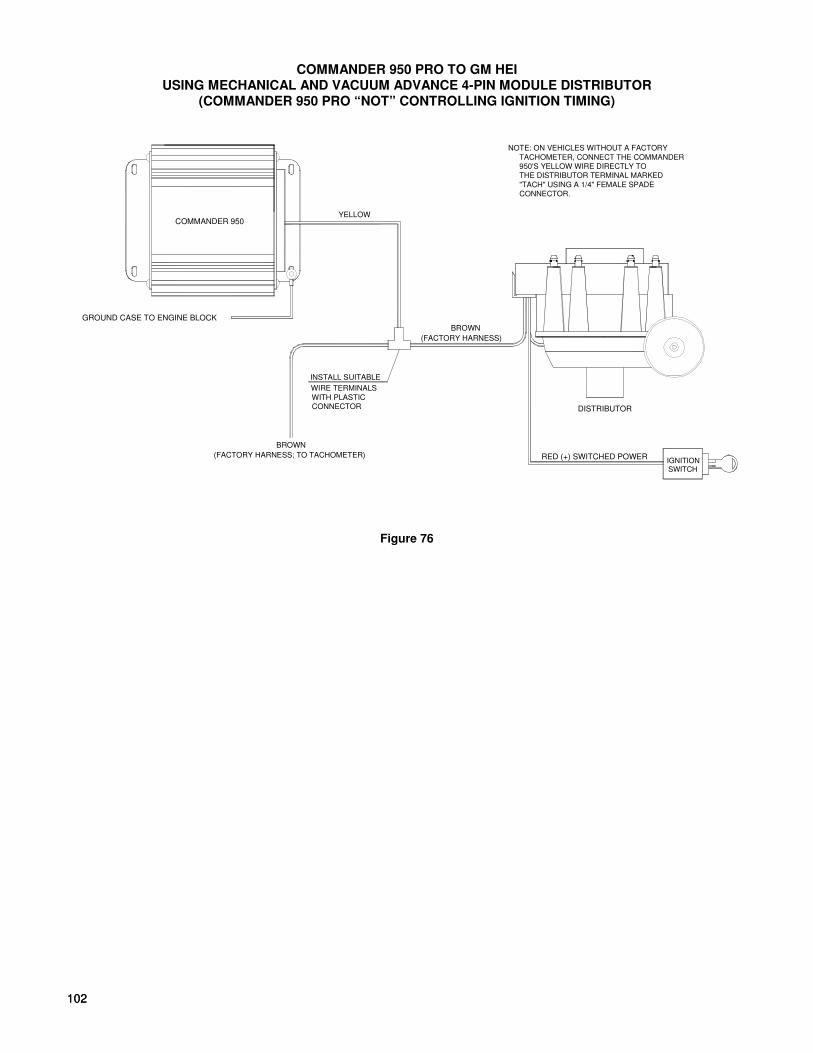
102 102
COMMANDER 950 PRO TO GM HEI USING MECHANICAL AND VACUUM ADVANCE 4-PIN MODULE DISTRIBUTOR
(COMMANDER 950 PRO “NOT” CONTROLLING IGNITION TIMING)
COMMANDER 950
INSTALL SUITABLE
WIRE TERMINALS
WITH PLASTICCONNECTOR
(FACTORY HARNESS)
YELLOW
BROWN
BROWN
(FACTORY HARNESS; TO TACHOMETER)
DISTRIBUTOR
NOTE: ON VEHICLES WITHOUT A FACTORY
TACHOMETER, CONNECT THE COMMANDER
950'S YELLOW WIRE DIRECTLY TO
THE DISTRIBUTOR TERMINAL MARKED
"TACH" USING A 1/4" FEMALE SPADE
CONNECTOR.
GROUND CASE TO ENGINE BLOCK
RED (+) SWITCHED POWERIGNITIONSWITCH
Figure 76
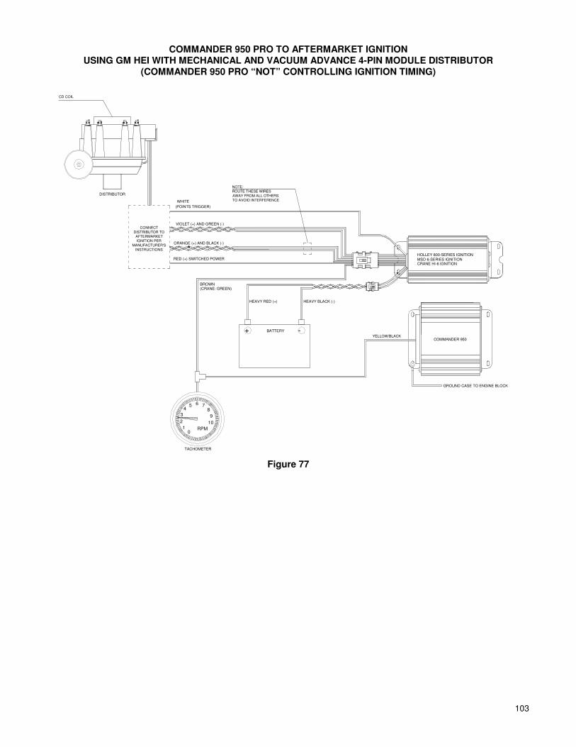
103
COMMANDER 950 PRO TO AFTERMARKET IGNITION USING GM HEI WITH MECHANICAL AND VACUUM ADVANCE 4-PIN MODULE DISTRIBUTOR
(COMMANDER 950 PRO “NOT” CONTROLLING IGNITION TIMING)
5
TACHOMETER
0
2
1
3
4
RPM
10
9
76
8
BATTERY+ -
ORANGE (+) AND BLACK (-)
VIOLET (+) AND GREEN (-)
RED (+) SWITCHED POWER
(CRANE: GREEN)BROWN
HEAVY RED (+) HEAVY BLACK (-)
HOLLEY 800-SERIES IGNITION
MSD 6-SERIES IGNITIONCRANE HI-6 IGNITION
COMMANDER 950YELLOW/BLACK
DISTRIBUTOR
GROUND CASE TO ENGINE BLOCK
WHITE
(POINTS TRIGGER)
CONNECT
DISTRIBUTOR TO AFTERMARKET
IGNITION PER
MANUFACTURER'S
INSTRUCTIONS
CD COIL
NOTE:
ROUTE THESE WIRES
AWAY FROM ALL OTHERS
TO AVOID INTERFERENCE
Figure 77
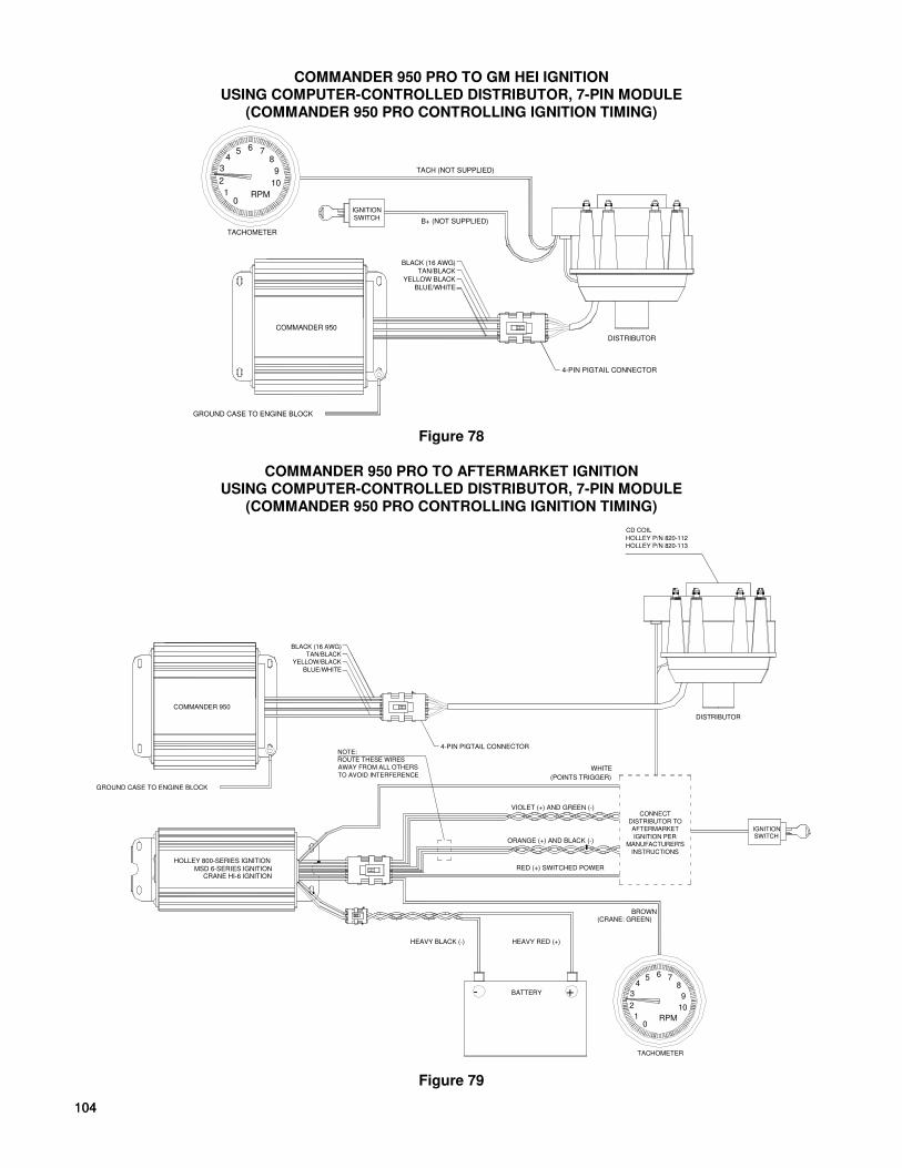
104 104
COMMANDER 950 PRO TO GM HEI IGNITION USING COMPUTER-CONTROLLED DISTRIBUTOR, 7-PIN MODULE
(COMMANDER 950 PRO CONTROLLING IGNITION TIMING)
COMMANDER 950
BLACK (16 AWG)
TAN/BLACK
YELLOW BLACK
BLUE/WHITE
DISTRIBUTOR
4-PIN PIGTAIL CONNECTOR
GROUND CASE TO ENGINE BLOCK
B+ (NOT SUPPLIED)
TACH (NOT SUPPLIED)
5
TACHOMETER
0
2
1
3
4
RPM
10
9
76
8
IGNITIONSWITCH
Figure 78
COMMANDER 950 PRO TO AFTERMARKET IGNITION
USING COMPUTER-CONTROLLED DISTRIBUTOR, 7-PIN MODULE (COMMANDER 950 PRO CONTROLLING IGNITION TIMING)
COMMANDER 950
BLACK (16 AWG)
TAN/BLACK
YELLOW/BLACK
BLUE/WHITE
DISTRIBUTOR
4-PIN PIGTAIL CONNECTOR
GROUND CASE TO ENGINE BLOCK
IGNITIONSWITCH
CONNECT
DISTRIBUTOR TO AFTERMARKET
IGNITION PER
MANUFACTURER'S
INSTRUCTIONS
VIOLET (+) AND GREEN (-)
RED (+) SWITCHED POWER
ORANGE (+) AND BLACK (-)
(CRANE: GREEN)
1
3
2
RPM
TACHOMETER
0
45 6
8
10
7
9
BROWN
HEAVY RED (+)
+BATTERY
WHITE
(POINTS TRIGGER)
CRANE HI-6 IGNITIONMSD 6-SERIES IGNITION
HOLLEY 800-SERIES IGNITION
HEAVY BLACK (-)
-
HOLLEY P/N 820-112
HOLLEY P/N 820-113
CD COIL
NOTE:
ROUTE THESE WIRES
AWAY FROM ALL OTHERS
TO AVOID INTERFERENCE
Figure 79

105
COMMANDER 950 PRO TO GM HEI IGNITION USING COMPUTER-CONTROLLED DISTRIBUTOR, EXTERNAL COIL
(COMMANDER 950 PRO CONTROLLING TIMING)
COMMANDER 950
QUICK DISCONNECT
BY-PASSES COMMANDER 950 TIMING
BLACK (16 AWG)
TAN/BLACK
YELLOW/BLACK
BLUE/WHITE
HOLLEY ADAPTER
P/N 534-138
TO REVERT TO HEI MODULE TIMING
INDUCTIVE COIL
IGNITIONSWITCH
(+) SWITCHED POWER
(-)(+)
C (WHITE) + (PINK OR RED)
GROUND CASE TO ENGINE BLOCKMSD P/N 8366
HOLLEY P/N 890-160
DISTRIBUTOR
HOLLEY 820-214
Figure 80

10
6
10
6
CO
MM
AN
DE
R 9
50 P
RO
TO
AF
TE
RM
AR
KE
T IG
NIT
ION
U
SIN
G A
GM
7-P
IN S
TY
LE
DIS
TR
IBU
TO
R A
ND
EX
TE
RN
AL
CO
IL
(CO
MM
AN
DE
R 9
50 P
RO
CO
NT
RO
LL
ING
IG
NIT
ION
TIM
ING
)
COMMANDER 950
QUICK DISCONNECT
BY-PASSES COMMANDER 950 TIMING
DISTRIBUTOR
BLACK (16 AWG)
TAN/BLACK
YELLOW/BLACK
BLUE/WHITE
HOLLEY ADAPTER
P/N 534-138
TO REVERT TO HEI MODULE TIMING
HOLLEY P/N 890-160
IGNITIONSWITCH
(+) SWITCHED POWER
C (WHITE) + (PINK OR RED)
GROUND CASE TO ENGINE BLOCK
GREEN (TO CHASSIS GROUND)
HEAVY RED (+)
+3
TACHOMETER
RPM0
2
110
9
(CRANE: GREEN)
45 6
87
BROWN
BATTERY
HEAVY BLACK (-)
RED (+) SWITCHED POWER
-
ORANGE (+) BLACK (-)
NOT USED
VIOLET (+) AND GREEN (-)
ORANGE (+) AND BLACK (-)
CRANE HI-6 IGNITIONMSD 6-SERIES IGNITIONHOLLEY 800-SERIES IGNITION
(POINTS TRIGGER)
WHITE
MSD P/N 8366
HOLLEY P/N 820-100
CD COIL
(HARNESS NOT SUPPLIED)
NOTE:
ROUTE THESE WIRES
AWAY FROM ALL OTHERS
TO AVOID INTERFERENCE
F
igu
re 8
1
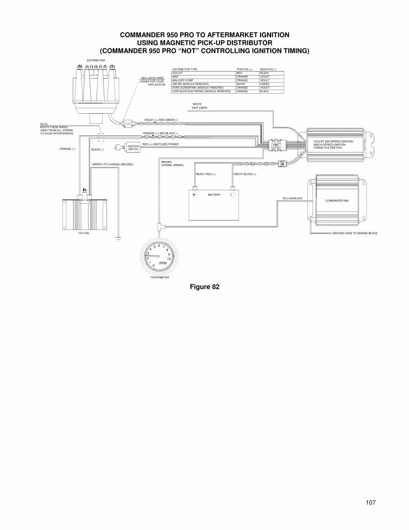
107
COMMANDER 950 PRO TO AFTERMARKET IGNITION USING MAGNETIC PICK-UP DISTRIBUTOR
(COMMANDER 950 PRO “NOT” CONTROLLING IGNITION TIMING)
5
TACHOMETER
0
2
1
3
4
RPM
10
9
76
8
BATTERY+ -
ORANGE (+) AND BLACK (-)
VIOLET (+) AND GREEN (-)
RED (+) SWITCHED POWER
(CRANE: GREEN)BROWN
HEAVY RED (+) HEAVY BLACK (-)
HOLLEY 800-SERIES IGNITIONMSD 6-SERIES IGNITIONCRANE HI-6 IGNITION
WHITE
(NOT USED)
SWITCHIGNITION
ORANGE (+)
GREEN (TO CHASSIS GROUND)
BLACK (-)
DISTRIBUTOR
CD COIL
COMMANDER 950YELLOW/BLACK
GROUND CASE TO ENGINE BLOCK
SEE LISTED WIRE
CODES FOR YOUR
APPLICATION
ORANGE BLACK
VIOLETORANGE
GREENGM HEI (MODULE REMOVED) WHITE
VIOLETMALLORY COMP ORANGE
VIOLETMSD ORANGE
BLACKHOLLEY RED
NEGATIVE (-)DISTRIBUTOR TYPE POSITIVE (+)
FORD DURASPARK (MODULE REMOVED)
CHRYSLER ELECTRONIC (MODULE REMOVED)
NOTE:
ROUTE THESE WIRES AWAY FROM ALL OTHERS
TO AVOID INTERFERENCE
Figure 82

108 108
COMMANDER 950 PRO TO AFTERMARKET IGNITION USING MAGNETIC PICK-UP CRANK TRIGGER
(COMMANDER 950 PRO CONTROLLING IGNITION TIMING)
ORANGE (+) AND BLACK (-)
RED (+) SWITCHED POWERIGNITION
VIOLET (+)
GREEN (-)
APPLICATION
SEE LISTED WIRE
CODES FOR YOUR
CONNECTORWITH PLASTIC
WIRE TERMINALS
INSTALL SUITABLE
MSD 6-SERIES IGNITION
SENSORPICKUP
TRIGGERWHEEL
CRANK
VIOLET (+) AND GREEN (-)
NOT USED
GREEN (-)
VIOLET (+)
WHITE
0RPM
10
9
8765
4
3
2
1
+ -
TACHOMETER
BATTERY
HEAVY BLACK (-)
COMMANDER 950
CD COIL
ORANGE (+) BLACK (-)
GREEN (TO CHASSIS GROUND)
(POINTS TRIGGER)
CRANE HI-6 IGNITION
HOLLEY 800-SERIES IGNITION
(CRANE: GREEN)
GROUND CASE TO (-) TERMINAL OF BATTERY
CRANK
TRIGGER
IGNITION SIGNAL FLOW CHART
SENDS SIGNAL
TO
COMMANDER 950
SENDS SIGNAL
TO
AFTERMARKET
IGNITION BOXSENDS SIGNAL
TO
IGNITION COIL
WHICH FIRES
SPARK PLUG
HARNESS P/N
534-135 (MAGNETIC PICK-UP)
MOROSO
FIREPOWER
CRANK TRIGGER TYPE
MSD (LATE)
MSD (EARLY)
HOLLEY LASERSTRIKE (EARLY)
HOLLEY LASERSTRIKE (LATE)
NEGATIVE (-)POSITIVE (+)
VIOLET
ORANGE
GREY OR ORANGE
BLACK
BLACK
VIOLET
WHITE
WHITE
GREEN
BLACK
GREEN
BLACK
NOTE:
ROUTE THESE WIRES
AWAY FROM ALL OTHERS
TO AVOID INTERFERENCE
HEAVY RED (+)
WHITE
BROWN
SWITCH
Figure 83

109
COMMANDER 950 PRO TO AFTERMARKET IGNITION USING HALL EFFECT PICK-UP CRANK TRIGGER
(COMMANDER 950 PRO CONTROLLING IGNITION TIMING)
ORANGE (+) AND BLACK (-)
RED (+) SWITCHED POWERIGNITION
MSD 6-SERIES IGNITION
SENSORPICKUP
TRIGGERWHEEL
CRANK
HEAVY RED (+)
WHITE
BROWN
SWITCH
VIOLET (+) AND GREEN (-)
NOT USED
0RPM
10
9
8765
4
3
2
1
+ -
TACHOMETER
BATTERY
HEAVY BLACK (-)
COMMANDER 950
CD COIL
ORANGE (+) BLACK (-)
GREEN (TO CHASSIS GROUND)
(POINTS TRIGGER)
CRANE HI-6 IGNITION
HOLLEY 800-SERIES IGNITION
(CRANE: GREEN)
GROUND CASE TO (-) TERMINAL OF BATTERY
CRANK
TRIGGER
IGNITION SIGNAL FLOW CHART
SENDS SIGNAL
TO
COMMANDER 950
SENDS SIGNAL
TO
AFTERMARKET IGNITION BOX
SENDS SIGNAL
TO
IGNITION COIL
WHICH FIRES
SPARK PLUG
BLACK
RED
WHITEYELLOW/BLACK
BLACK
NOTE:
ROUTE THESE WIRES
AWAY FROM ALL OTHERS
TO AVOID INTERFERENCE
Figure 84
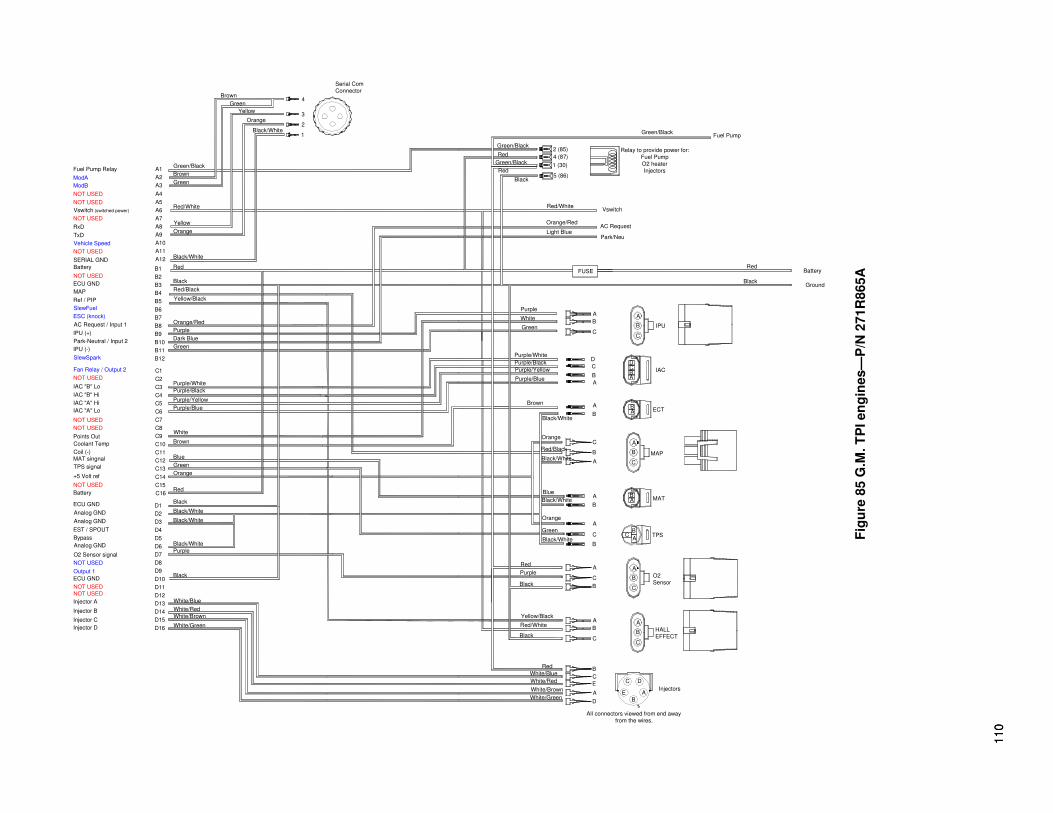
11
0
11
0
Orange
Green
Black/White
Blue
Black/White
Red/Black
Orange
Black/White
B
A
A
B
BA
C
A
B
A
C
B MAP
Red
Relay to provide power for:
Fuel Pump
O2 heater
Injectors
IAC
IPU
Purple/White
Purple/Blue
Purple/Yellow
Purple/Black
Brown
White
Purple
Green
A
A
C
B
D
BECT
C
AB
D
B
C
A
B
C
A
Orange/Red
Light Blue
Black
Red/White
5 (86)
Park/Neu
FUSE
AC Request
Vswitch
Black
RedBattery
Ground
Green/Black
Green/Black
Green/Black
Red2 (85)
4 (87)
1 (30)
Fuel Pump
Analog GND
EST / SPOUT
Analog GND
ECU GND
Battery
Coolant Temp
TPS signal
MAT singnal
Points Out
NOT USED
NOT USED
Coil (-)
D12
White/Green
White/Brown
White/Red
White/Blue
D16
D13
D15
D14
Black
Purple
Black/White
D8
D11
D10
D9
D7
D5
D6
C14Orange
Black/White
Black/White
BlackD1
D3
D4
D2
C16
C15Red
Green
Brown
White
C10
C11
C12
C13
Blue
C8
C9
C7
Fuel Pump Relay
MAP
NOT USED
IAC "A" Lo
IAC "A" Hi
IAC "B" Hi
IAC "B" Lo
Fan Relay / Output 2
SlewSpark
AC Request / Input 1
ESC (knock)
Park-Neutral / Input 2
IPU (+)
IPU (-)
Ref / PIP
SlewFuel
TxD
SERIAL GND
NOT USED
Vehicle Speed
ECU GND
NOT USED
Battery
NOT USED
NOT USED
NOT USED
Vswitch (switched power)
RxD
ModA
ModB
A1Brown
B4
B11
Purple/Blue
Purple/Yellow
Purple/Black
Purple/White
C5
C4
C3
B12
C1
C2
Yellow/Black
Green
Dark Blue
Purple
Orange/RedB8
B10
B9
B6
B7
B5
A9Orange
Red/Black
Black
Black/White
B2
B3
B1 Red
A11
A12
A10
Yellow
Red/White
Green
A5
A7
A8
A6
A3
A4
A2
Brown
Green/Black
3Yellow
Black/White
Orange2
1
Green4
Serial Com
Connector
AB
All connectors viewed from end away
from the wires.
Injectors
White/Blue
White/Red
White/Brown
White/Green
Red
E
D
A
B
C
A
B
E
C D
MAT
HALL
EFFECT
O2
Sensor
CC TPS
Yellow/Black
Red/White
Black
Purple
Red
Black
Black/White
B
C
A A
C
B
A
C
B
B
B
C
A
A
C6
Bypass
NOT USED
Injector D
Injector C
Injector B
Injector A
O2 Sensor signal
Analog GND
NOT USED
ECU GND
NOT USED
Output 1
+5 Volt ref
NOT USED
F
igu
re 8
5 G
.M. T
PI en
gin
es—
P/N
271R
865A
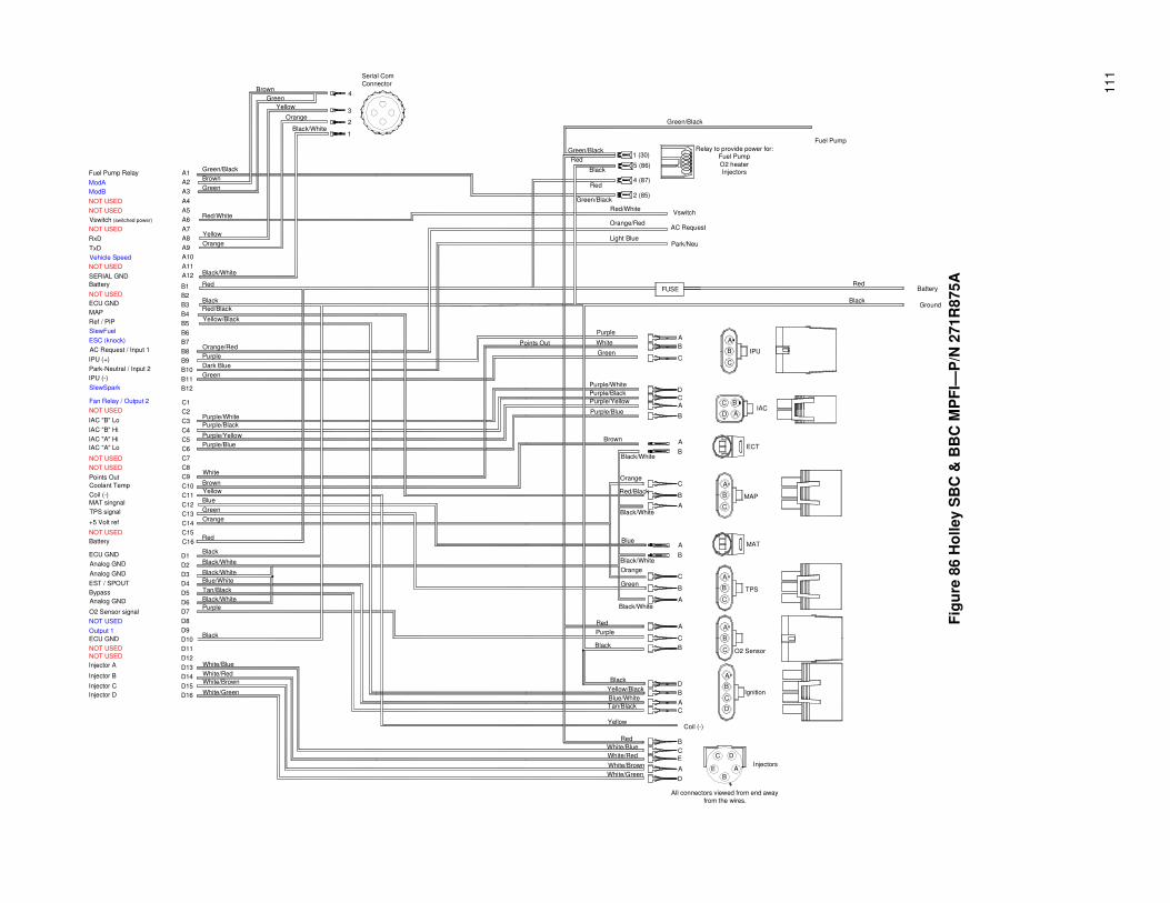
1
11
D8
D16
D14
D15
D11
D12
D13
D9
D10
B2
B12
D3
D6
D7
D4
D5
D1
D2
B7
B11
B10
B9
B8
B4
B6
B5
B3
B1
C15
C5
C2
C1
C3
C4
C10
C6
C7
C8
C9
C13
C11
C12
C14
C16
A1
A2
A3
A4
A5
A6
A7
A8
A9
A10
A11
A12
Ignition
Serial Com
Connector
Ground
Battery
Fuel Pump
O2 Sensor
ECT
MAP
MAT
TPS
IAC
IPU
Coil (-)
Vswitch
Park/Neu
Relay to provide power for:Fuel Pump
O2 heaterInjectors
Points Out
Injectors
C
E
B
A
D
AC Request
FUSE
4
3
2
1
Brown
Green/Black
Green
Red/White
Yellow
Orange
Black/White
Red
Black
Yellow/Black
Orange/Red
Purple
Dark Blue
Green
Purple/White
Purple/Black
Purple/Yellow
Purple/Blue
White
Brown
Yellow
Blue
Green
Orange
Red
Black
Black/White
Black/White
Blue/White
Tan/Black
Black/White
Purple
Black
White/Blue
White/Red
White/Brown
White/Green
Red/Black
5 (86)
1 (30)
4 (87)
2 (85)
A
B
C
D
CA
B
C
B
A
A
B
C
B
A
A
C
D
B
A
C
B
C
E
A
DWhite/Green
White/Brown
White/Red
White/Blue
Red
Yellow
Tan/Black
Blue/White
Yellow/Black
Black
Purple
Red
Black
Green
Orange
Blue
Red/Black
Brown
Purple/White
Purple/Black
Purple/Yellow
Purple/Blue
Green
Purple
Green/Black
Green/Black
Black
Red
Green/Black
Red
Black
Red/White
Orange/Red
Light Blue
Brown
Green
Yellow
Orange
Black/White
Red
White
C
B
A
A
BC
D
B
A
B
C
Black/White
Black/White
Black/White
Black/White
Orange
B
All connectors viewed from end away
from the wires.
A
D
B
A
C
B
C
A
C
B
A
AC Request / Input 1
Battery
Injector D
NOT USED
Injector A
Injector B
Injector C
NOT USED
O2 Sensor signal
Bypass
Output 1
NOT USED
ECU GND
Analog GND
ECU GND
Analog GND
EST / SPOUT
Analog GND
IAC "A" Lo
Coolant Temp
Coil (-)
MAT singnal
TPS signal
NOT USED
+5 Volt ref
NOT USED
NOT USED
Points Out
Fan Relay / Output 2
Park-Neutral / Input 2
IAC "B" Lo
IAC "B" Hi
IAC "A" Hi
NOT USED
IPU (-)
IPU (+)
SlewSpark
TxD
Vehicle Speed
NOT USED
ECU GND
SlewFuel
Ref / PIP
ESC (knock)
MAP
Battery
NOT USED
SERIAL GND
(switched power)
Fuel Pump Relay
NOT USED
RxD
Vswitch
NOT USED
NOT USED
ModB
ModA
F
igu
re 8
6 H
olley S
BC
& B
BC
MP
FI—
P/N
271R
875A

11
2
11
2
IPU (-)
IPU (+)
SlewSpark
TxD
Vehicle Speed
NOT USED
ECU GND
SlewFuel
Ref / PIP
ESC (knock)
MAP
Battery
NOT USED
SERIAL GND
(switched power)
Fuel Pump Relay
NOT USED
RxD
Vswitch
NOT USED
NOT USED
ModB
ModA
AC Request / Input 1
Battery
Injector D
NOT USED
Injector A
Injector B
Injector C
NOT USED
O2 Sensor signal
Bypass
Output 1
NOT USED
ECU GND
Analog GND
ECU GND
Analog GND
EST / SPOUT
Analog GND
IAC "A" Lo
Coolant Temp
Coil (-)
MAT singnal
TPS signal
NOT USED
+5 Volt ref
NOT USED
NOT USED
Points Out
Fan Relay / Output 2
Park-Neutral / Input 2
IAC "B" Lo
IAC "B" Hi
IAC "A" Hi
NOT USED
Points Out
Purple/Yellow
D3 Black/White
D10
D14
D16
D15
D12
D13
D11
White/Red
White/Green
White/Brown
White/Blue
D8
D9
D7
D5
D6
D4
Purple
Black
Black/White
Tan/Black
Blue/White
BlueC12
D1
D2
C16
C14
C15
C13
Red
Black/White
Black
Orange
Green
C8
C10
C11
C9
C6
C7
C5
Brown
Yellow
White
Purple/Blue
B2
Dark Blue
C1
C4
C3
C2
B11
B12
B10
Purple/Black
Purple/White
Green
B6
B8
B9
B7
B4
B5
B3
Orange/Red
Purple
Red/Black
Yellow/Black
Black
A7
B1
A12
A11
A9
A10
A8
Black/White
Red
Orange
Yellow
A3
A5
A6
A4
A1
A2
Red/White
Green/Black
Brown
Green
1
2
3
4Brown
Black/White
Orange
Green
Yellow
Serial Com
Connector
DTan/BlackC
All connectors viewed from end away
from the wires.
White/Blue
White/Red
White/Brown
White/Green
Yellow
Red
D B
Coil (-)
B
E
A
CC
E A
D
Injectors
Ignition
MAP
Orange
Black/White
Black
Black
Yellow/Black
Blue/White
Red
Purple
Green
BC
IAC
IPU
BlackGround
RedBattery
Green/Black
2 (85)Green/Black
Fuel Pump
B
A
D
B
A
C
B
C
A
B
A
C
A
B
C
A
Black/White
Black/White
Black/White
Red/Black
Blue
Orange
Brown
A
B
A
B
A
C
C
B
B
A
A
B
O2 Sensor
TPS
MAT
ECT
Red 4 (87)Relay to provide power for:
Fuel Pump
O2 heaterInjectors
Purple/Blue
Purple/Yellow
Purple/Black
Purple/White
White
Purple
Green
C
B
A
D
C
B
C
A
B
A
Light Blue
Orange/Red
Red/White
1 (30)
5 (86)Black
Green/Black
Red
AC Request
Park/Neu
FUSE
Vswitch
Fig
ure
87 H
olley 4
BB
L T
BI—
P/N
271R
884A

113
C6
Byp
ass
NO
T U
SE
D
Inje
cto
r D
Inje
cto
r C
Inje
cto
r B
Inje
cto
r A
O2
Se
nso
r sig
na
l
An
alo
g G
ND
NO
T U
SE
D
EC
U G
ND
NO
Se
na
ble
NO
S1
+5
Vo
lt r ef
NO
T U
SE
D
An
alo
g G
ND
ES
T / S
PO
UT
An
alo
g G
ND
EC
U G
ND
Ba
ttery
Co
ola
nt T
em
p
TP
S s
ign
al
MA
T s
ing
na
l
Po
ints
Ou
t
NO
T U
SE
D
NO
T U
SE
D
Co
il (- )
D12
Wh
ite/G
ree
n
Wh
ite/B
row
n
Wh
ite/R
ed
Wh
ite/B
lue
D16
D13
D15
D14
Bla
ck
Purp
le
Bla
ck/W
hite
D8
D11
D10
D9
D7
D5
D6
C1
4O
ran
ge
Bla
ck/W
hite
Bla
ck/W
hite
Bla
ck
D1
D3
D4
D2
C1
6
C1
5R
ed
Gre
en
Bro
wn
Wh
ite
C1
0
C1
1
C1
2
C1
3
Blu
e
C8
C9
C7
Fu
el P
um
p R
ela
y
MA
P
NO
T U
SE
D
IAC
"A" L
o
IAC
"A" H
i
IAC
"B" H
i
IAC
"B" L
o
Co
olin
g F
an
Re
lay
Sle
wS
pa
rk
AC
Re
qu
est
ES
C (k
no
ck)
Pa
rk / N
eu
tral
IPU
(+)
IPU
(- )
Re
f / PIP
Sle
wF
ue
l
TxD
SE
RIA
L G
ND
NO
T U
SE
D
Ve
hic
le S
pe
ed
EC
U G
ND
NO
T U
SE
D
Ba
ttery
NO
T U
SE
D
NO
T U
SE
D
NO
T U
SE
D
Vsw
itch
(sw
itch
ed
po
we
r)
RxD
Mo
dA
Mo
dB
A1
Bro
wn
B4
B1
1
Purp
le/B
lue
Purp
le/Y
ello
w
Pu
r ple
/Bla
ck
Purp
le/W
hite
C5
C4
C3
B1
2
C1
C2
Yello
w/B
lack
Gre
en
Dark
Blu
e
Purp
le
Ora
ng
e/R
ed
B8
B1
0
B9
B6
B7
B5
A9
Ora
ng
e
Red
/Bla
ck
Bla
ck
Bla
ck/W
hite
B2
B3
B1
Red
A1
1
A1
2
A1
0
Yello
w
Red
/Wh
ite
Gre
en
A5
A7
A8
A6
A3
A4
A2
Bro
wn
Gre
en
/Bla
ck
3Y
ello
wBla
ck/W
hite
Ora
ng
e21
Gre
en
4
Se
rial C
om
Co
nn
ecto
r
AB
All c
onne
ctors
vie
wed fro
m e
nd a
way
from
the w
ires.
Inje
cto
rs
White
/Blu
e
White
/Red
White
/Bro
wn
White
/Gre
en
Red
ED A BC
A
B
E
CD
MA
T
HA
LL
EF
FE
CT
O2
Sen
sor
CC
TP
S
Ye
llow
/Bla
ck
Red/W
hite
Bla
ck
Purp
le
Red
Bla
ck
Bla
ck/W
hite
BC AAC B
ACB B
BC A A
Ora
nge
Gre
en
Bla
ck/W
hite
Blu
e
Bla
ck/W
hite
Red
/Bla
ck
Ora
nge
Bla
ck/W
hite
BA A
B BA
CA B
AC BM
AP
Red
Rela
y to
pro
vid
e p
ow
er fo
r:
Fu
el P
um
p
O2 h
eate
rIn
jecto
rs
IAC
IPU
Purp
le/W
hite
Purp
le/B
lue
Purp
le/Y
ello
w
Pur p
le/B
lack
Bro
wn
White
Purp
le
Gre
en
AA CB D
BE
CT
CA B D
BC A
BC A
Ora
nge/R
ed
Lig
ht B
lue
Bla
ck
Red
/White
5 (8
6)
Park
/Neu
FU
SE
AC
Request
Vsw
itch
Bla
ck
Red
Ba
ttery
Gro
un
d
Gre
en/B
lack
Gre
en/B
lack
Gre
en
/Bla
ck
Red
2 (8
5)
4 (8
7)
1 (3
0)
Fu
el P
um
p
Figure 88 G.M. LT1/LT4 engine—P/N 271R886A
114 114
Holley Performance Products 1801 Russellville Road
Bowling Green, KY 42101-3542
Toll Free Technical Service: 1-866-GOHOLLEY Technical Service: 1-270-781-9741
Fax: 1-270-781-9772 For online help, please refer to the Tech Service section of our website: www.holley.com
Holley Performance Products Limited Warranty
All Holley Performance Products Limited Warranties are extended to the original consumer only. This Limited Warranty is not assignable or otherwise transferable. There are no warranties that extend beyond those stated herein. Holley Performance Products offers no other warranties expressed or implied beyond this Limited Warranty.
In the event of an alleged defect in material or workmanship, Holley Performance Products’ responsibility is strictly limited to repair or replace the defective product. Holley has no other obligation expressed or implied. Final warranty determination will be in the sole discretion of Holley Performance Products. Holley shall not be responsible for; (a) actual or alleged labor, transportation, or other incidental charges; or (b) actual or alleged consequential or other damages incurred by use of any product of Holley Performance Products.
To initiate the warranty process, the consumer must return the alleged defective product to the place of purchase with a dated receipt and completed applicable warranty claim tag. Warranty claims will be rejected if the date of purchase cannot be established by the consumer. Do not send products directly to Holley Performance Products. Holley Performance Products assumes no responsibility for products sent directly to Holley Performance Products.
This Limited Warranty sets forth specific legal rights. The consumer may have other rights as a result of variations in state laws or provincial laws. This Limited Warranty supersedes all prior warranty statements.
HOLLEY/ANNIHILATOR/FLOWTECH/HOOKER/NOS/WEIAND – NEW PRODUCT
Holley Performance Products warrants its new Holley, Annihilator, Flowtech, Hooker, NOS, and Weiand products to be free from defects in material and workmanship for a period of 90 days from date of purchase.
Holley Performance Products Limited Warranty specifically does not apply to products, which have been (a) modified or altered in any way; (b) subjected to adverse conditions, such as misuse, neglect, accident, improper installation or adjustment, dirt or other contaminants, water, corrosion, or faulty repair; or (c) used in other than those applications recommended by Holley Performance Products. Holley Performance Products also does not warrant, and disclaims all liability for products used in racing activities and/or applications other than those specifically recommended in the current brand catalog.
Holley limits the warranty on Metallic Ceramic Coatings to be free from defects in material and workmanship for a period of 90 days from the date of purchase. This limited coating warranty does not apply to any products which have been subjected to adverse conditions, such as high heat encountered during engine break-in or if used during any racing activity. MARINE PRODUCTS Holley Performance Products warrants its new marine products to be free from defects in material and workmanship for a period of 90 days from date of purchase. For the safety and protection of persons and property, all United States Coast Guard and other marine product safety installation and use requirements and recommendations must be carefully studied and applied. The above recommendations include, but are not limited to the recommendation that the installation, adjustment, and repair of Holley carburetors or other marine products must be performed only by a trained mechanic having adequate marine fuel system experience, and in strict compliance with the applicable Holley installation, maintenance, and other instructions. Failure to follow such requirements and recommendations will void this Holley Marine Limited Warranty, and Holley disclaims any responsibility and/or liability for accidents resulting from such failure. Holley Performance Products Limited Warranty specifically does not apply to products, which have been (a) modified or altered in any way; (b) subjected to adverse conditions, such as misuse, neglect, accident, improper installation or adjustment, dirt or other contaminants, water, corrosion, or faulty repair; or (c) used in other than those applications recommended by Holley Performance Products. Holley Performance Products also does not warrant, and disclaims all liability for products used in racing activities and/or applications other than those specifically recommended in the current brand catalog.
Holley Printed in U.S.A. 199R-10149-7 Date: 7-12-04 Performance Products, Inc.
Copyright © 2004 by Holley Performance Products, Inc. Any unauthorized reproduction of this manual without the express written
permission of Holley Performance Products, Inc. is strictly prohibited.