comfort and energy savings - energie transfert thermique · comfort and energy savings october 2014...
TRANSCRIPT

Comfortand energysavings
October 2014 edition
0.1.0.2.3 CTA CH Rooftop Single Flow Air Handling UnitHigh Energy Performance range
A different c l imateEnvironmental control solutions
CTA CH : Single Flow Air Handling Unit
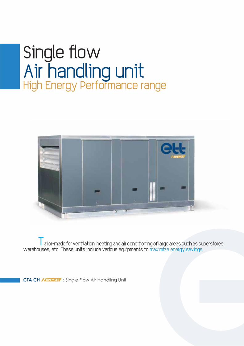
Single fl owAir handling unitHigh Energy Performance range
Tailor-made for ventilation, heating and air conditioning of large areas such as superstores, warehouses, etc. These units include various equipments to maximize energy savings.

CTA CH
ummary
A different climateEnvironmental control solutionsnv
mu
ico
General description ........................................................................................................................................... 05Principle of operation ....................................................................................................................................... 06Description ............................................................................................................................................................... 07Options......................................................................................................................................................................... 08
Technical featuresType 10 ......................................................................................................................................................................... 09Type 20 ......................................................................................................................................................................... 15Type 30 ......................................................................................................................................................................... 21Type 40 ......................................................................................................................................................................... 27
Dimensions and connectionsType 10Supply air below .................................................................................................................................................... 10Supply air on top ................................................................................................................................................... 11Supply air below - return air at the end ................................................................................................. 12Supply air on side .................................................................................................................................................. 13Supply air at the end .......................................................................................................................................... 14Type 20Supply air below .................................................................................................................................................... 16Supply air on top ................................................................................................................................................... 17Supply air below - return air at the end ................................................................................................. 18Supply air on side .................................................................................................................................................. 19Supply air at the end .......................................................................................................................................... 20Type 30Supply air below .................................................................................................................................................... 22Supply air on top ................................................................................................................................................... 23Supply air below - return air at the end ................................................................................................. 24Supply air on side .................................................................................................................................................. 25Supply air at the end .......................................................................................................................................... 26Type 40Supply air below .................................................................................................................................................... 28Supply air on top ................................................................................................................................................... 29Supply air on side .................................................................................................................................................. 30Supply air at the end .......................................................................................................................................... 31
ArrangementsSupply air downwards ....................................................................................................................................... 32Supply air upwards ............................................................................................................................................... 33Other arrangements ........................................................................................................................................... 34
Installation accessoriesRoof curb general description .................................................................................................................... 36Adjustable connection roof curb .............................................................................................................. 37Adjustable ventilated roof curb .................................................................................................................. 38"Free Heating" adjustable connection roof curb ............................................................................ 39"Free Heating" adjustable ventilated roof curb ............................................................................... 40Roof curbs laying principle ............................................................................................................................. 41
AuxiliaryHot water coil .......................................................................................................................................................... 42Electric heaters ....................................................................................................................................................... 43Water recovery coils ........................................................................................................................................... 44
Sound levelin supply air mode ................................................................................................................................................ 46In return air mode ................................................................................................................................................. 47
Probes connection scheme .......................................................................................................................... 48
E n e r g i eTr a n s f e r tThermique
5CTA CH HPE+ CEE - 10/2014 - 0.1.0.2.3
ETT may change equipment data & design without prior notice.Specifi cations and data in this document are not contractual.
• 2006/42/EC machine Directive - Safety prescriptions• 2006/95/EC low voltage Directive - Electricity• EMC 2004/108/EC Directive - Electromagnetic
compatibility
• 2009/142/EC directive• EN 1886 - Air treatment box mechanical performances• EN 60204-1 - Electrical appliances
Moreover, each unit is delivered with an EC standard conformity certifi cate and respects standards below listed:
The ETT packaged unit, delivered ready to operate, is made of aluminium frame & casing, giving an extremely high resistance to the elements (20-year warranty against corrosion). The ETT unit can be installed at ground level (plantroom) or on a roof. GREEN DESIGN involves DECONSTRUCTION: ETT units are 98% recyclable (re-use and recycling rates based on CH 99 RR HPE+).
Each unit, prior to shipment, is checked and tested at the factory, with issue of a test certifi cate.ETT Quality organization is certifi ed ISO 9001 (AFNOR Certifi cate 1994/2016f).
We placed ease of operation at the heart of our units design: • a separated technical section facilitates service and control of the unit and allows measurement and
adjustment during operation.• the BEST controller specifi cally designed for this application, allows great fl exibility of operation and therefore
optimum performance of the ETT unit, it being user-friendly whether it is with local or remote (with remote display, PC or BMS) communication.
• Law: European directive 2008/98/EC of 19th November 2008: - The 26th point: "The polluter-pays principle is a guiding principle at European and international levels.The waste producer and the waste holder should manage the waste in a way that guarantees a high level of protection of the environment and human health".• Energy: ETT, innovator in Heat Transfer solutions.• Aluminium: a good choice for the planet!- aluminium is 100% recyclable and endlessly.- recycling gives 30% of aluminium needs.• Low polluting ETT manufacturing process:- sorting done by job. All wastes are recycled. No paint, no use of water.- ISO 14001 Certifi cation (Environmental Management System).- ETT has been recognized able to manipulate refrigerant fl uid as stipulated by the F-gas Regulation European Directive, and more particularly, the fi fth Article "minimum requirements and the conditions for mutual recognition shall be established in accordance with the procedure referred to in Article 12(2) in respect of training programmes and certifi cation for both the companies and the relevant personnel involved in installation, maintenance or servicing of the equipment and systems covered by Article 3(1)" which are "refrigeration, air conditioning and heat pump equipment".
• An effi cient waste management:- fi ltration: ETT includes "green-designed" air fi lters (sorting frame - grille - media).
Our technical choices have several impacts on the environment:
General description

6 CTA CH HPE+ CEE - 10/2014 - 0.1.0.2.3
ETT may change equipment data & design without prior notice.Specifi cations and data in this document are not contractual.
Operating modes can be:> Heating> Air conditioner> "Free cooling": cooling with external air, without
thermodynamics
The unit can operate:> In all recycling mode> In all fresh air mode> In mixing mode
The ETT package comprises 2 different sections:1/ a separated technical section including hydraulic components, electric board and regulating
elements.2/ an internal section for air change and handling.
Aluminium frame and casing assembly designed with:- a rigid, compact, lightweight and weather-resistant casing that includes a 20-year corrosion-resistant warranty on
frame & casing.- a watertight fl oor with drainage outlets located at the border of the unit and linked to rubber siphons. - vertical AG3-type aluminium panels and roof. - access through large "easy to remove" panels. Access to components is made through large "easy to remove"
lockable aluminium panels. Doors tightness is ensured by fl exible gasket under compression, providing an ideal elasticity day after day.
- inside acoustic and thermal insulation made by M0 glass wool, 50 mm thickness. The insulation is reinforced in the ventilation section.- fl oor acoustic and thermal insulation made by double skin M0 rock wool, 100 mm thickness. - 2-damper mixing box with motorized fresh air damper with bird proof grid and return air damper ensuring the
desired proportions and optimizing "free cooling" economizer phases. Dampers have class 3 extruded aluminium blades with low pressure drop. The damper frame is made of aluminium.
Principle of operation

7CTA CH HPE+ CEE - 10/2014 - 0.1.0.2.3
ETT may change equipment data & design without prior notice.Specifi cations and data in this document are not contractual.
Air assembly designed with:- easy-to-remove green-designed fi lters - 98 mm, folded, 95% ASHRAE gravimetric (G4) effi ciency, fouling controlled
by pressure-switch. - free wheeling supply air fan. This technology avoids losses due to pulley-belt transmissions.- motor with:
• reduced kickback during the starting for textile ducts (soft start mode).• maximum rotation speed regulation according to pressure drops on site.• reduced speed operation in free-cooling mode to save energy.
- supply air fan compliant with EuP 2013 / ErP 2015 directives.- internal exchanger: Water change over coil made with copper pipes and aluminium fi ns and frame. This coil can
be supplied with hot or chilled water to ensure a heating or cooling operation.
Electrical assembly designed with:an electrical board that complies with European standards EN 15-100 and EN 60204-01, and includes: - ETT controller with display.- disconnector with lockable external handle to cut in full load.- 400-230-24 volts transformer for control circuits.- fault synthesis with pending dry contact on terminal.- numbered terminal blocks with disconnecting terminals for remote controls or transfers.- internal wiring numbered at both extremities using numbered ferrules.- Ik3 breaking capacity of basis 10 kA.- components protection using circuit breakers.
Control assembly designed with:- one or more BEST-type controllers (Building Energy Saving Technology) especially developed by ETT for this range
of units. Programs update is done once a year in order to add functions requested for some applications and to optimize units electricity consumption. The microprocessor, memory and controllers size are adapted to the chosen applications and options by integrating a program set-up in the factory out of 160 possible confi gurations. The controller is in a plastic box which guarantees a high mechanical protection and reduces electrostatic shocks threats.
- CTN type temperature sensors. Their accuracy and liability have been tested and validated at the factory and on site.
The controller has the following functions:- on / off with remote contact or unoccupancy contact.- on / off according to operating hours (2 slots per day).- fault synthesis with dry contact for transfer on customer system.- 2 setpoints (cooling and heating) according to European directive 2002/91/EC.- security management (fi re thermostat, smoke detector...) and faults management.- "free-cooling" economizer management by analysing internal temperature and comparing return and outside
air temperatures.- out-of-frost restart.- written faults history (no code needed) displaying hour and outside temperature.- unit and auxiliaries operating hours counting.- air quality control with CO2 sensor to optimize the quantity of fresh air to introduce, therefore limiting energy
consumption.
Description
8 CTA CH HPE+ CEE - 10/2014 - 0.1.0.2.3
ETT may change equipment data & design without prior notice.Specifi cations and data in this document are not contractual.
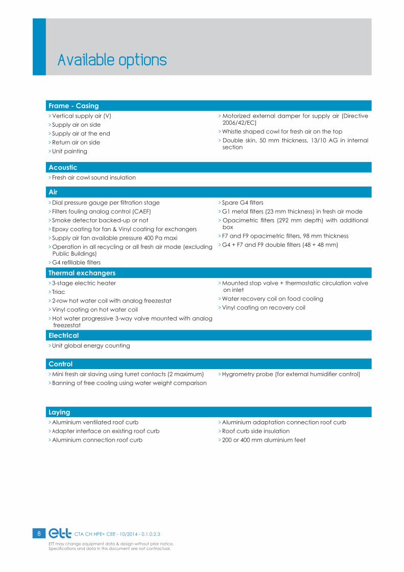
Frame - Casing> Vertical supply air (V)> Supply air on side> Supply air at the end> Return air on side> Unit painting
> Motorized external damper for supply air (Directive 2006/42/EC)
> Whistle shaped cowl for fresh air on the top> Double skin, 50 mm thickness, 13/10 AG in internal
section
Acoustic> Fresh air cowl sound insulation
Air> Dial pressure gauge per fi ltration stage> Filters fouling analog control (CAEF)> Smoke detector backed-up or not> Epoxy coating for fan & Vinyl coating for exchangers> Supply air fan available pressure 400 Pa maxi> Operation in all recycling or all fresh air mode (excluding
Public Buildings)> G4 refi llable fi lters
> Spare G4 fi lters> G1 metal fi lters (23 mm thickness) in fresh air mode> Opacimetric fi lters (292 mm depth) with additional
box> F7 and F9 opacimetric fi lters, 98 mm thickness > G4 + F7 and F9 double fi lters (48 + 48 mm)
Thermal exchangers> 3-stage electric heater > Triac > 2-row hot water coil with analog freezestat> Vinyl coating on hot water coil> Hot water progressive 3-way valve mounted with analog
freezestat
> Mounted stop valve + thermostatic circulation valve on inlet
> Water recovery coil on food cooling> Vinyl coating on recovery coil
Electrical> Unit global energy counting
Control> Mini fresh air slaving using turret contacts (2 maximum)> Banning of free cooling using water weight comparison
> Hygrometry probe (for external humidifi er control)
Laying> Aluminium ventilated roof curb> Adapter interface on existing roof curb> Aluminium connection roof curb
> Aluminium adaptation connection roof curb > Roof curb side insulation> 200 or 400 mm aluminium feet
Available options

9CTA CH HPE+ CEE - 10/2014 - 0.1.0.2.3
ETT may change equipment data & design without prior notice.Specifi cations and data in this document are not contractual.
Specifi cations Unit 10 10 10Rated air fl ow rate for 200 Pa m3 / h 5500 7500 9900Mini / Maxi air fl ow rate m3 / h 4500 / 12000 6500 / 12000 8500 / 12000
Heating powersAir exchanger's inlet at -7° 95% HR water supply 90°/70° kW 101 126 154
Air exchanger's inlet at -7° 95% HR water supply 45°/35° kW 54 67 82
Air exchanger's inlet at 20° 50% HR water supply 90°/70° kW 70 87 106
Air exchanger's inlet at 20° 50% HR water supply 45°/40° kW 27 33 41
Cooling powersAir exchanger's inlet at 27° 47% HR water supply 5°/11° kW 13 23 29
Air exchanger's inlet at 27° 47% HR water supply 6°/12° kW 13 20 27
Air exchanger's inlet at 35° 40% HR water supply 5°/11° kW 31 37 44
Air exchanger's inlet at 35° 40% HR water supply 6°/12° kW 29 35 42
Water fl ow rate in heating modeAir exchanger's inlet at -7° 95% HR water supply 90°/70° m3 / h 4.4 5.5 6.5
Air exchanger's inlet at -7° 95% HR water supply 45°/35° m3 / h 4.6 5.7 6.5
Air exchanger's inlet at 20° 50% HR water supply 90°/70° m3 / h 3.1 3.8 4.6
Air exchanger's inlet at 20° 50% HR water supply 45°/40° m3 / h 4.5 5.6 6.5
Water fl ow rate in cooling modeAir exchanger's inlet at 27° 47% HR water supply 5°/11° m3 / h 2.1 3.4 4.3
Air exchanger's inlet at 27° 47% HR water supply 6°/12° m3 / h 2.0 3.0 4.0
Air exchanger's inlet at 35° 40% HR water supply 5°/11° m3 / h 4.5 5.5 6.4
Air exchanger's inlet at 35° 40% HR water supply 6°/12° m3 / h 4.2 5.2 6.1
Electrical connection200 Pa total installed electrical power (***) kW 3.7 3.7 4.1
Rated / Start current at 200 Pa A 6.3 / 7.9 6.3 / 7.9 6.9 / 9.4
400 Pa total installed electrical power (***) kW 3.7 3.7 5.7
Rated / Start current at 400 Pa A 6.3 / 7.9 6.3 / 7.9 9.3 / 13
Fan200 Pa absorbed electrical / installed mechanical power (***) kW 1.07 / 2.7 1.67 / 2.7 2.29 / 3.1400 Pa absorbed electrical / installed mechanical power (***) kW 1.6 / 2.7 2.28 / 2.7 2.61 / 4.72002/91/EC - Fans total regulatory capacity
200 Pa "Central air savings" kW 0.59 0.88 1.14
2002/91/EC - Fans total regulatory capacity400 Pa "Central air savings" kW 1.13 1.58 1.74
2002/91/EC - Ventilation average capacity per 200 Pa fl ow rate unit W/(m3/h) 0.20 0.22 0.232002/91/EC - Ventilation average capacity per 400 Pa fl ow rate unit W/(m3/h) 0.29 0.30 0.26
GeneralAverage sound pressure at 10 m, reference: 2x10⁻⁵ in free fi eld dB(A) 42 48 48Filters effi ciency G4 (98 mm) G4 (98 mm) G4 (98 mm)
Filters dimensions & number mm (4x) 595 x 498 x 98(2x) 595 x 287 x 98
Unit weight without any option (****) kg 480 480 492Connection roof curb weight kg 87 87 87Standard ventilated roof curb weight kg 120 120 120Connection roof curb weight with fi lter box kg 105 105 105Ventilated roof curb weight with fi lter box kg 150 150 150
*** Out of electrical resistances - **** For hot water coils and electric heaters weight, please consult "Auxiliaries". For installation accessories weight, please consult "Installation accessories". 400V - 50 Hz + earth without neutral 3-phase power supply.
Technical featuresType 10

10 CTA CH HPE+ CEE - 10/2014 - 0.1.0.2.3
ETT may change equipment data & design without prior notice.Specifi cations and data in this document are not contractual.
SUPPLY AIR belowSide view
Top view
Return air view
Supply air view
1625
306
1
2
150 500 160
3
A A
A A
C
1950
2
400
3
16801200 345135
2
1
500 310
3
Length Width Height
Casing dimensions 1950 mm 1680 mm 1625 mm
Transport overall dimensions 2000 mm 1730 mm 1675 mm
Nota:Nota: Fresh air cowls laying shall be made by the installer.
1 Fresh Air 2 Return air3 Supply airA Access
Power supplyC Technical section
Dimensions and connectionsType 10

11CTA CH HPE+ CEE - 10/2014 - 0.1.0.2.3
ETT may change equipment data & design without prior notice.Specifi cations and data in this document are not contractual.
Side view
Top view
Return air view
Supply air view
SUPPLY AIR on top
Length Width Height
Casing dimensions 1950 mm 1680 mm 1625 mm
Transport overall dimensions 2000 mm 1730 mm 1675 mm
Nota:Nota: Fresh air cowls laying shall be made by the installer.
1 Fresh Air 2 Return air3 Supply airA Access
Power supplyC Technical section
Dimensions and connectionsType 10
1625
1
125 310
2 3
A A
A A
C
1950
2
400
3
310
500
500 160
1680
1
1200 345
2
135
3

12 CTA CH HPE+ CEE - 10/2014 - 0.1.0.2.3
ETT may change equipment data & design without prior notice.Specifi cations and data in this document are not contractual.
Dimensions and connectionsType 10
SUPPLY AIR below, return air on sideSide view
Top view
Return air view
Supply air view
Length Width Height
Casing dimensions 1950 mm 1680 mm 1625 mm
Transport overall dimensions 2000 mm 1730 mm 1675 mm
Nota:Nota: Fresh air cowls laying shall be made by the installer.
1 Fresh Air 2 Return air3 Supply airA Access
Power supplyC Technical section
1625
1
2
3
500 160
A A
A A
C
3
1950400
2
1
16801200 345
310
358
1200 345
356
213
135
135
3500 310
13CTA CH HPE+ CEE - 10/2014 - 0.1.0.2.3
ETT may change equipment data & design without prior notice.Specifi cations and data in this document are not contractual.
Side view
Top view
Return air view
Supply air view
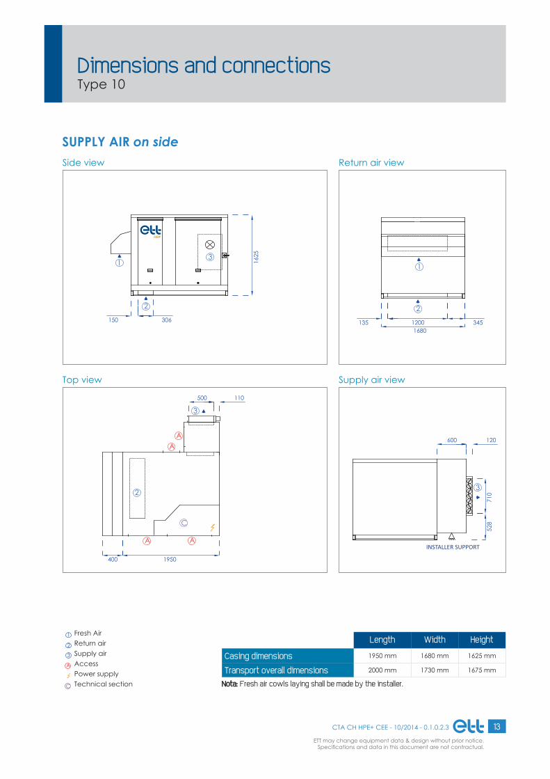
SUPPLY AIR on side
Length Width Height
Casing dimensions 1950 mm 1680 mm 1625 mm
Transport overall dimensions 2000 mm 1730 mm 1675 mm
Nota:Nota: Fresh air cowls laying shall be made by the installer.
1 Fresh Air 2 Return air3 Supply airA Access
Power supplyC Technical section
Dimensions and connectionsType 10
1625
306
1
2
150
3
A
A A
C
1950
2
400
A
3
500 110
16801200 345135
2
1
371
0
SUPPORTAGEINSTALLATEUR
600 120
528
INSTALLER SUPPORT

14 CTA CH HPE+ CEE - 10/2014 - 0.1.0.2.3
ETT may change equipment data & design without prior notice.Specifi cations and data in this document are not contractual.
Dimensions and connectionsType 10
SUPPLY AIR at the endSide view
Top view
Return air view
Supply air view
Length Width Height
Casing dimensions 1950 mm 1680 mm 1625 mm
Transport overall dimensions 2000 mm 1730 mm 1675 mm
Nota:Nota: Fresh air cowls laying shall be made by the installer.
1 Fresh Air 2 Return air3 Supply airA Access
Power supplyC Technical section
1625
306
1
2
150
575
610
440
3
A A
A A
C
1950
2
400
240
700
740
3
16801200 345135
2
1
3

15CTA CH HPE+ CEE - 10/2014 - 0.1.0.2.3
ETT may change equipment data & design without prior notice.Specifi cations and data in this document are not contractual.
Technical featuresType 20
Specifi cations Unit 20 20 20 20Rated air fl ow rate for 200 Pa m3 / h 12000 14000 16000 21000Mini / Maxi air fl ow rate m3 / h 10000 / 22000 12000 / 22000 14000 / 22000 17000 / 22000
Heating powersAir exchanger's inlet at -7° 95% HR water supply 90°/70° kW 194 217 238 285
Air exchanger's inlet at -7° 95% HR water supply 45°/35° kW 103 115 126 152
Air exchanger's inlet at 20° 50% HR water supply 90°/70° kW 133 149 163 196
Air exchanger's inlet at 20° 50% HR water supply 45°/40° kW 51 57 63 76
Cooling powersAir exchanger's inlet at 27° 47% HR water supply 5°/11° kW 23 23 24 40
Air exchanger's inlet at 27° 47% HR water supply 6°/12° kW 21 22 23 24
Air exchanger's inlet at 35° 40% HR water supply 5°/11° kW 53 59 65 76
Air exchanger's inlet at 35° 40% HR water supply 6°/12° kW 49 56 61 77
Water fl ow rate in heating modeAir exchanger's inlet at -7° 95% HR water supply 90°/70° m3 / h 8.6 9.5 10.5 12.5
Air exchanger's inlet at -7° 95% HR water supply 45°/35° m3 / h 8.8 9.8 10.8 12.9
Air exchanger's inlet at 20° 50% HR water supply 90°/70° m3 / h 5.9 6.5 7.2 8.6
Air exchanger's inlet at 20° 50% HR water supply 45°/40° m3 / h 8.6 9.6 10.5 12.6
Water fl ow rate in cooling modeAir exchanger's inlet at 27° 47% HR water supply 5°/11° m3 / h 3.4 3.6 3.8 6.2
Air exchanger's inlet at 27° 47% HR water supply 6°/12° m3 / h 3.2 3.4 3.5 3.9
Air exchanger's inlet at 35° 40% HR water supply 5°/11° m3 / h 7.8 8.8 9.6 11.3
Air exchanger's inlet at 35° 40% HR water supply 6°/12° m3 / h 7.2 8.3 9.1 11.5
Electrical connection200 Pa total installed electrical power (***) kW 5.7 5.7 7.2 7.2
Rated / Start current at 200 Pa A 9.3 / 13 9.3 / 13 11.8 / 16.7 11.8 / 16.7
400 Pa total installed electrical power (***) kW 5.7 5.7 7.2 10.4
Rated / Start current at 400 Pa A 9.3 / 13 9.3 / 13 11.8 / 16.7 16.6 / 23.9
Fan200 Pa absorbed electrical / installed mechanical power (***) kW 2.38 / 4.7 3.22 / 4.7 3.36 / 6.2 5.34 / 6.2400 Pa absorbed electrical / installed mechanical power (***) kW 3.22 / 4.7 4.11 / 4.7 4.8 / 6.2 5.87 / 9.42002/91/EC - Fans total regulatory capacity
200 Pa "Central air savings" kW 1.26 1.64 1.66 2.44
2002/91/EC - Fans total regulatory capacity400 Pa "Central air savings" kW 2.23 2.77 3.17 3.69
2002/91/EC - Ventilation average capacity per 200 Pa fl ow rate unit W/(m3/h) 0.20 0.23 0.21 0.252002/91/EC - Ventilation average capacity per 400 Pa fl ow rate unit W/(m3/h) 0.27 0.29 0.30 0.28
GeneralAverage sound pressure at 10 m, reference: 2x10⁻⁵ in free fi eld dB(A) 52 56 48 52Filters effi ciency G4 (98 mm) G4 (98 mm) G4 (98 mm) G4 (98 mm)
Filters dimensions & number mm (6x) 595 x 498 x 98(3x) 595 x 287 x 98
Unit weight without any option (****) kg 689 687 759 808Connection roof curb weight kg 124 124 124 124Standard ventilated roof curb weight kg 185 185 185 185Connection roof curb weight with fi lter box kg 153 153 153 153Ventilated roof curb weight with fi lter box kg 210 210 210 210
*** Out of electrical resistances - **** For hot water coils and electric heaters weight, please consult "Auxiliaries". for installation accessories weight, please consult "Installation accessories". 400V - 50 Hz + earth without neutral 3-phase power supply.

16 CTA CH HPE+ CEE - 10/2014 - 0.1.0.2.3
ETT may change equipment data & design without prior notice.Specifi cations and data in this document are not contractual.
SUPPLY AIR belowSide view
Top view
Return air view
Supply air view
2750
1690
900 1603
150 506
650
1
2
AAA
A A
C
32
2200
1800 2652
1
135
4807103
1010
Length Width Height
Casing dimensions 2750 mm 2200 mm 1690 mm
Transport overall dimensions 2800 mm 2250 mm 1740 mm
Nota:Nota: Fresh air cowls laying shall be made by the installer.
1 Fresh Air 2 Return air3 Supply airA Access
Power supplyC Technical section
Dimensions and connectionsType 20

17CTA CH HPE+ CEE - 10/2014 - 0.1.0.2.3
ETT may change equipment data & design without prior notice.Specifi cations and data in this document are not contractual.
Side view
Top view
Return air view
Supply air view
SUPPLY AIR on top
Length Width Height
Casing dimensions 2750 mm 2200 mm 1690 mm
Transport overall dimensions 2800 mm 2250 mm 1740 mm
Nota:Nota: Fresh air cowls laying shall be made by the installer.
1 Fresh Air 2 Return air3 Supply airA Access
Power supplyC Technical section
Dimensions and connectionsType 20
2750
1690
1608003
1
150 5102
AAA
A A
C
32
2200
475
510
1
2
135 1800 265
3
435800965

18 CTA CH HPE+ CEE - 10/2014 - 0.1.0.2.3
ETT may change equipment data & design without prior notice.Specifi cations and data in this document are not contractual.
Dimensions and connectionsType 20
SUPPLY AIR below, return air on sideSide view
Top view
Return air view
Supply air view
Length Width Height
Casing dimensions 2750 mm 2200 mm 1690 mm
Transport overall dimensions 2800 mm 2250 mm 1740 mm
Nota:Nota: Fresh air cowls laying shall be made by the installer.
1 Fresh Air 2 Return air3 Supply airA Access
Power supplyC Technical section
2750
1690
900 1603
650
1
2
AAA
A A
C
3
2200
1800 265
135 1800
135
265
217
510
170
556
1
2
4807103
1010

19CTA CH HPE+ CEE - 10/2014 - 0.1.0.2.3
ETT may change equipment data & design without prior notice.Specifi cations and data in this document are not contractual.
Side view
Top view
Return air view
Supply air view
SUPPLY AIR on side
Length Width Height
Casing dimensions 2750 mm 2200 mm 1690 mm
Transport overall dimensions 2800 mm 2250 mm 1740 mm
Nota:Nota: Fresh air cowls laying shall be made by the installer.
1 Fresh Air 2 Return air3 Supply airA Access
Power supplyC Technical section
Dimensions and connectionsType 20
2750
1690
150 506
650
1
2
3
AAA
A
C
2
A
3
500 160
2200
1800 2652
1
135
428
3
1010
600 120
SUPPORTAGEINSTALLATEUR
INSTALLER SUPPORT

20 CTA CH HPE+ CEE - 10/2014 - 0.1.0.2.3
ETT may change equipment data & design without prior notice.Specifi cations and data in this document are not contractual.
Dimensions and connectionsType 20
SUPPLY AIR at the endSide view
Top view
Return air view
Supply air view
Length Width Height
Casing dimensions 2750 mm 2200 mm 1690 mm
Transport overall dimensions 2800 mm 2250 mm 1740 mm
Nota:Nota: Fresh air cowls laying shall be made by the installer.
1 Fresh Air 2 Return air3 Supply airA Access
Power supplyC Technical section
2750
1690
150 506
650
1
2
3
525
810
355
AAA
A A
C
32
340
1000
860
2200
1800 2652
1
135
3

21CTA CH HPE+ CEE - 10/2014 - 0.1.0.2.3
ETT may change equipment data & design without prior notice.Specifi cations and data in this document are not contractual.
Technical featuresType 30
Specifi cations Unit 30 30 30Rated air fl ow rate for 200 Pa m3 / h 22000 24000 30000Mini / Maxi air fl ow rate m3 / h 18000 / 33000 22000 / 33000 24000 / 33000
Heating powersAir exchanger's inlet at -7° 95% HR water supply 90°/70° kW 322 342 396
Air exchanger's inlet at -7° 95% HR water supply 45°/35° kW 171 182 210
Air exchanger's inlet at 20° 50% HR water supply 90°/70° kW 221 235 272
Air exchanger's inlet at 20° 50% HR water supply 45°/40° kW 84 90 103
Cooling powersAir exchanger's inlet at 27° 47% HR water supply 5°/11° kW 34 34 63
Air exchanger's inlet at 27° 47% HR water supply 6°/12° kW 32 32 56
Air exchanger's inlet at 35° 40% HR water supply 5°/11° kW 89 94 107
Air exchanger's inlet at 35° 40% HR water supply 6°/12° kW 84 89 109
Water fl ow rate in heating modeAir exchanger's inlet at -7° 95% HR water supply 90°/70° m3 / h 14.2 15.1 17.5
Air exchanger's inlet at -7° 95% HR water supply 45°/35° m3 / h 14.6 15.5 18.0
Air exchanger's inlet at 20° 50% HR water supply 90°/70° m3 / h 9.7 10.3 11.9
Air exchanger's inlet at 20° 50% HR water supply 45°/40° m3 / h 14.3 15.1 17.5
Water fl ow rate in cooling modeAir exchanger's inlet at 27° 47% HR water supply 5°/11° m3 / h 5.1 5.3 9.4
Air exchanger's inlet at 27° 47% HR water supply 6°/12° m3 / h 4.8 4.9 8.4
Air exchanger's inlet at 35° 40% HR water supply 5°/11° m3 / h 13.0 13.7 15.6
Air exchanger's inlet at 35° 40% HR water supply 6°/12° m3 / h 12.3 13.1 16.0
Electrical connection200 Pa total installed electrical power (***) kW 10.4 10.4 15.1
Rated / Start current at 200 Pa A 16.6 / 23.9 16.6 / 23.9 23.9 / 34.9
400 Pa total installed electrical power (***) kW 10.4 10.4 15.1
Rated / Start current at 400 Pa A 16.6 / 23.9 16.6 / 23.9 23.9 / 34.9
Fan200 Pa absorbed electrical / installed mechanical power (***) kW 4.36 / 9.4 5.05 / 9.4 6.22 / 14.1400 Pa absorbed electrical / installed mechanical power (***) kW 5.94 / 9.4 6.76 / 9.4 8.52 / 14.12002/91/EC - Fans total regulatory capacity
200 Pa "Central air savings" kW 2.15 2.44 2.77
2002/91/EC - Fans total regulatory capacity400 Pa "Central air savings" kW 3.92 4.39 5.25
2002/91/EC - Ventilation average capacity per 200 Pa fl ow rate unit W/(m3/h) 0.20 0.21 0.212002/91/EC - Ventilation average capacity per 400 Pa fl ow rate unit W/(m3/h) 0.27 0.28 0.28
GeneralAverage sound pressure at 10 m, reference: 2x10⁻⁵ in free fi eld dB(A) 52 55 51Filters effi ciency G4 (98 mm) G4 (98 mm) G4 (98 mm)
Filters dimensions & number mm (6x) 595 x 595 x 98(3x) 595 x 498 x 98
Unit weight without any option (****) kg 1096 1104 1175Connection roof curb weight kg 151 151 151Standard ventilated roof curb weight kg 200 200 200Connection roof curb weight with fi lter box kg 186 186 186Ventilated roof curb weight with fi lter box kg 260 260 260
*** Out of electrical resistances - **** For hot water coils and electric heaters weight, please consult "Auxiliaries". For installation accessories weight, please consult "Installation accessories". 400V - 50 Hz + earth without neutral 3-phase power supply.

22 CTA CH HPE+ CEE - 10/2014 - 0.1.0.2.3
ETT may change equipment data & design without prior notice.Specifi cations and data in this document are not contractual.
SUPPLY AIR belowSide view
Top view
Return air view
Supply air view
353021
30
31601100
900
1
2606110
C
AA
AAA
C
AA
AAA
32
2200
21800 265
1
455
610
135
3350900950
Length Width Height
Casing dimensions 3530 mm 2200 mm 2130 mm
Transport overall dimensions 3580 mm 2250 mm 2180 mm
Nota:Nota: Fresh air cowls laying shall be made by the installer.
1 Fresh Air 2 Return air3 Supply airA Access
Power supplyC Technical section
Dimensions and connectionsType 30

23CTA CH HPE+ CEE - 10/2014 - 0.1.0.2.3
ETT may change equipment data & design without prior notice.Specifi cations and data in this document are not contractual.
Side view
Top view
Return air view
Supply air view
SUPPLY AIR on top
Length Width Height
Casing dimensions 3530 mm 2200 mm 2130 mm
Transport overall dimensions 3580 mm 2250 mm 2180 mm
Nota:Nota: Fresh air cowls laying shall be made by the installer.
1 Fresh Air 2 Return air3 Supply airA Access
Power supplyC Technical section
Dimensions and connectionsType 30
2130
16011003
1
2110 610
3530
C
AA
AAA
C
AA
AAA
32
1
455
610
2
135 1800 265
2200
3
950 900 350
24 CTA CH HPE+ CEE - 10/2014 - 0.1.0.2.3
ETT may change equipment data & design without prior notice.Specifi cations and data in this document are not contractual.
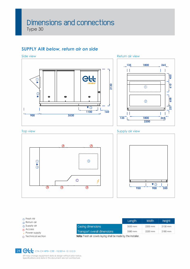
SUPPLY AIR below, return air on sideSide view
Top view
Return air view
Supply air view
Length Width Height
Casing dimensions 3530 mm 2200 mm 2130 mm
Transport overall dimensions 3580 mm 2250 mm 2180 mm
Nota:Nota: Fresh air cowls laying shall be made by the installer.
1 Fresh Air 2 Return air3 Supply airA Access
Power supplyC Technical section
Dimensions and connectionsType 30
2130
31601100
900
1
2
3530
C
AA
AAA
C
AA
AAA
31
2
22001800 265
455
610
237
658
135 1800 265
1
2
135
3350900950

25CTA CH HPE+ CEE - 10/2014 - 0.1.0.2.3
ETT may change equipment data & design without prior notice.Specifi cations and data in this document are not contractual.
Side view
Top view
Return air view
Supply air view
SUPPLY AIR on side
Length Width Height
Casing dimensions 3530 mm 2200 mm 2130 mm
Transport overall dimensions 3580 mm 2250 mm 2180 mm
Nota:Nota: Fresh air cowls laying shall be made by the installer.
1 Fresh Air 2 Return air3 Supply airA Access
Power supplyC Technical section
Dimensions and connectionsType 30
3530
2130
3530
2130
900
1
2606110
3
C
A
AAA
C
A
AAA
2
A
3
800 150
22002200
21800 265
1
455
610
135
434
314
10
SUPPORTAGEINSTALLATEUR
600 120
INSTALLER SUPPORT

26 CTA CH HPE+ CEE - 10/2014 - 0.1.0.2.3
ETT may change equipment data & design without prior notice.Specifi cations and data in this document are not contractual.
SUPPLY AIR at the endSide view
Top view
Return air view
Supply air view
Length Width Height
Casing dimensions 3530 mm 2200 mm 2130 mm
Transport overall dimensions 3580 mm 2250 mm 2180 mm
Nota:Nota: Fresh air cowls laying shall be made by the installer.
1 Fresh Air 2 Return air3 Supply airA Access
Power supplyC Technical section
Dimensions and connectionsType 30
353021
303530
2130
3
900
1
2606110
715
1010
405
C
AA
AAA
C
AA
AAA
2
200
1200
800
3
22002200
21800 265
1
455
610
135
3

27CTA CH HPE+ CEE - 10/2014 - 0.1.0.2.3
ETT may change equipment data & design without prior notice.Specifi cations and data in this document are not contractual.
Technical featuresType 40
Specifi cations Unit 40 40Rated air fl ow rate for 200 Pa m3 / h 35000 40000Mini / Maxi air fl ow rate m3 / h 28000 / 44000 34000 / 44000
Heating powersAir exchanger's inlet at -7° 95% HR water supply 90°/70° kW 488 534
Air exchanger's inlet at -7° 95% HR water supply 45°/35° kW 259 284
Air exchanger's inlet at 20° 50% HR water supply 90°/70° kW 335 366
Air exchanger's inlet at 20° 50% HR water supply 45°/40° kW 129 141
Cooling powersAir exchanger's inlet at 27° 47% HR water supply 5°/11° kW 47 87
Air exchanger's inlet at 27° 47% HR water supply 6°/12° kW 44 74
Air exchanger's inlet at 35° 40% HR water supply 5°/11° kW 131 141
Air exchanger's inlet at 35° 40% HR water supply 6°/12° kW 134 144
Water fl ow rate in heating modeAir exchanger's inlet at -7° 95% HR water supply 90°/70° m3 / h 21.5 23.5
Air exchanger's inlet at -7° 95% HR water supply 45°/35° m3 / h 22.1 24.1
Air exchanger's inlet at 20° 50% HR water supply 90°/70° m3 / h 14.7 16.0
Air exchanger's inlet at 20° 50% HR water supply 45°/40° m3 / h 21.6 23.5
Water fl ow rate in cooling modeAir exchanger's inlet at 27° 47% HR water supply 5°/11° m3 / h 7.3 13.1
Air exchanger's inlet at 27° 47% HR water supply 6°/12° m3 / h 6.9 11.3
Air exchanger's inlet at 35° 40% HR water supply 5°/11° m3 / h 19.3 20.9
Air exchanger's inlet at 35° 40% HR water supply 6°/12° m3 / h 19.7 21.4
Electrical connection200 Pa total installed electrical power (***) kW 13.4 13.4
Rated / Start current at 200 Pa A 21.6 / 31.4 21.6 / 31.4
400 Pa total installed electrical power (***) kW 13.4 19.8
Rated / Start current at 400 Pa A 21.6 / 31.4 31.2 / 45.8
Fan200 Pa absorbed electrical / installed mechanical power (***) kW 8.02 / 12.4 10.08 / 12.4400 Pa absorbed electrical / installed mechanical power (***) kW 11.02 / 12.4 11.44 / 18.82002/91/EC - Fans total regulatory capacity
200 Pa "Central air savings" kW 3.68 4.44
2002/91/EC - Fans total regulatory capacity400 Pa "Central air savings" kW 6.93 7.00
2002/91/EC - Ventilation average capacity per 200 Pa fl ow rate unit W/(m3/h) 0.23 0.252002/91/EC - Ventilation average capacity per 400 Pa fl ow rate unit W/(m3/h) 0.31 0.29
GeneralAverage sound pressure at 10 m, reference: 2x10⁻⁵ in free fi eld dB(A) 52 55Filters effi ciency G4 (98 mm) G4 (98 mm)
Filters dimensions & number mm (9x) 595 x 595 x 98(3x) 595 x 498 x 98
Unit weight without any option (****) kg 1211 1246Connection roof curb weight kg 157 157Standard ventilated roof curb weight kg 225 225Connection roof curb weight with fi lter box kgVentilated roof curb weight with fi lter box kg
*** Out of electrical resistances - **** For hot water coils and electric heaters weight, please consult “Auxiliaries”. For installation accessories weight, please consult “Installation accessories”. 400V - 50 Hz + earth without neutral 3-phase power supply.
28 CTA CH HPE+ CEE - 10/2014 - 0.1.0.2.3
ETT may change equipment data & design without prior notice.Specifi cations and data in this document are not contractual.
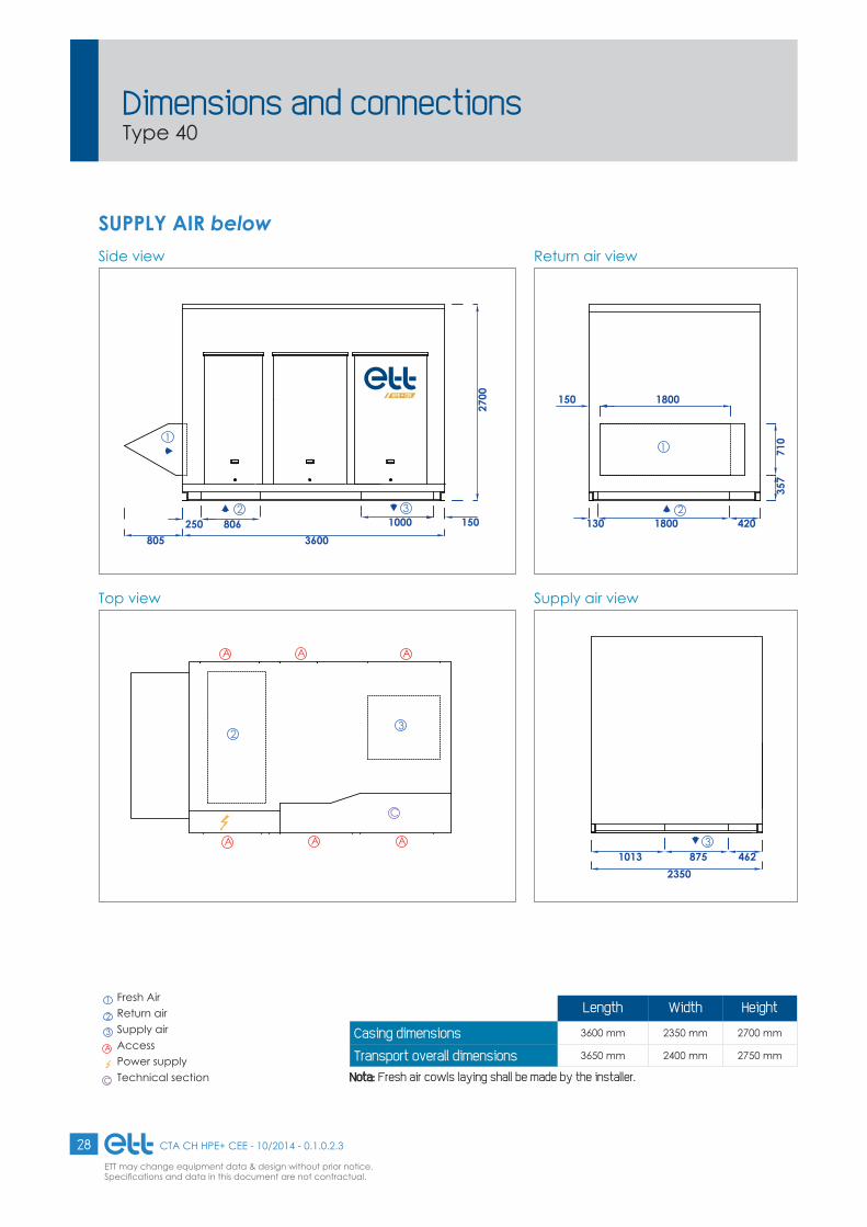
SUPPLY AIR belowSide view
Top view
Return air view
Supply air view
3600
2700
1
2250 806
805
31000 150
C
AAA
A A A
23
1
2130 1800 420
357
710
150 1800
2350
34628751013
Length Width Height
Casing dimensions 3600 mm 2350 mm 2700 mm
Transport overall dimensions 3650 mm 2400 mm 2750 mm
Nota:Nota: Fresh air cowls laying shall be made by the installer.
1 Fresh Air 2 Return air3 Supply airA Access
Power supplyC Technical section
Dimensions and connectionsType 40

29CTA CH HPE+ CEE - 10/2014 - 0.1.0.2.3
ETT may change equipment data & design without prior notice.Specifi cations and data in this document are not contractual.
Side view
Top view
Return air view
Supply air view
3600
2700
1
2250 810
805
1501000
3
C
AAA
A A A
23
1
130 1800 420
2
357
710
150 1800
2350
462
38751013
SUPPLY AIR on top
Length Width Height
Casing dimensions 3600 mm 2350 mm 2700 mm
Transport overall dimensions 3650 mm 2400 mm 2750 mm
Nota:Nota: Fresh air cowls laying shall be made by the installer.
1 Fresh Air 2 Return air3 Supply airA Access
Power supplyC Technical section
Dimensions and connectionsType 40

30 CTA CH HPE+ CEE - 10/2014 - 0.1.0.2.3
ETT may change equipment data & design without prior notice.Specifi cations and data in this document are not contractual.
SUPPLY AIR on sideSide view
Top view
Return air view
Supply air view
3600
2700
1
2250 806
805
3
C
A
A A A
2
AA
3
1000 150
1
2130 1800 420
357
710
4001800
2350
434
3
1410
SUPPORTAGEINSTALLATEUR
600 120
Length Width Height
Casing dimensions 3600 mm 2350 mm 2700 mm
Transport overall dimensions 3650 mm 2400 mm 2750 mm
Nota:Nota: Fresh air cowls laying shall be made by the installer.
1 Fresh Air 2 Return air3 Supply airA Access
Power supplyC Technical section
Dimensions and connectionsType 40
INSTALLER SUPPORT

31CTA CH HPE+ CEE - 10/2014 - 0.1.0.2.3
ETT may change equipment data & design without prior notice.Specifi cations and data in this document are not contractual.
Side view
Top view
Return air view
Supply air view
3600
2700
1
2250 806
805
695
1210
795
3
C
AA
A A A
32
A
250
1300
250
1
2130 1800 420
357
710
4001800
2350
3
SUPPLY AIR at the end
Length Width Height
Casing dimensions 3600 mm 2350 mm 2700 mm
Transport overall dimensions 3650 mm 2400 mm 2750 mm
Nota:Nota: Fresh air cowls laying shall be made by the installer.
1 Fresh Air 2 Return air3 Supply airA Access
Power supplyC Technical section
Dimensions and connectionsType 40

32 CTA CH HPE+ CEE - 10/2014 - 0.1.0.2.3
ETT may change equipment data & design without prior notice.Specifi cations and data in this document are not contractual.
Arrangement 1.1
1
1
1
1
1
12
2
2
2
2
2
3
3
33
3
3
Arrangement 1.2
Arrangement 1.4with whistle shaped cowl (optional)
Arrangement 1.6
Arrangement 1.8
Arrangement 1.10
Arrangement 1.3
Arrangement 1.5with whistle shaped cowl (optional)
Arrangement 1.7
Arrangement 1.9with whistle shaped cowl (optional)
1
2
31
2
3
1
2
3
1
2
3
Arrangements
SUPPLY AIR downwardsLaying on roof curb or customer frame on roof
1 Fresh air 2 Return air 3 Supply air

33CTA CH HPE+ CEE - 10/2014 - 0.1.0.2.3
ETT may change equipment data & design without prior notice.Specifi cations and data in this document are not contractual.
Arrangement 2.1
1
1
1
1
1
12
2
2
2
2
2
3
3
33
3
3
Arrangement 2.2
Arrangement 2.4with whistle shaped cowl (optional)
Arrangement 2.6
Arrangement 2.8
Arrangement 2.10
Arrangement 2.3
Arrangement 2.5with whistle shaped cowl (optional)
Arrangement 2.7
Arrangement 2.9with whistle shaped cowl (optional)
3
1
21
2
3
1 3
2
1
2
3
Arrangements
1 Fresh air 2 Return air 3 Supply air
SUPPLY AIR upwardsLaying on feet (400 mm minimum) or customer frame. Feet are optional. A supply air damper is necessary for units bigger than 10000 m3/h in Public Buildings.

34 CTA CH HPE+ CEE - 10/2014 - 0.1.0.2.3
ETT may change equipment data & design without prior notice.Specifi cations and data in this document are not contractual.
AB C
ED
ou1
2
ou1
2
ou1 2
ou1 2
ou1 2
Arrangements
"FRESH AIR" & "RETURN AIR" are similar to the corresponding unit dimensions and connections
Other arrangementsOptional: opacimetric fi lters box 292 mm depth
Dimension Unit 10 20 30 40A = B+ C mm 3705 5306 6886
OPTION NOT AVAILABLE
FOR SERIES 4
B mm 750 1100 1200
C mm 1950 2750 3530
D mm 1680 2200 2200
E mm 1625 1690 2130
Weight kg 150 220 330
1 Fresh air 2 Return air
OR
OR
OR
OR
OR

35CTA CH HPE+ CEE - 10/2014 - 0.1.0.2.3
ETT may change equipment data & design without prior notice.Specifi cations and data in this document are not contractual.
G
E
D
F
H
BA
C
B
E
A
D
Top viewSERIES 1-2-3
SERIES 4Top view
Side view
Side view
Dimension Unit 10 20 30 40A mm 180 202 251 250
B mm 415 551 614 335
C mm 329 367 367 385
D mm 450 480 630 700
E mm 700 700 800 1230
F mm 1625 1690 2130 2700
G mm 1400 1480 2130 2450
H mm 1680 2200 2200 2350
G F
HC
Other arrangementsWater recovery coil
Arrangements

36 CTA CH HPE+ CEE - 10/2014 - 0.1.0.2.3
ETT may change equipment data & design without prior notice.Specifi cations and data in this document are not contractual.
The roof curb provides interfacing between the roof and the rooftop unit. It has been designed for easy assembly on the roof and simplifi ed unit laying.
Adjustable packaged connection roof curb- Compliant with P 84-206-1 French standard (watertight ribbed sheet metal implement).- the packaged AG3 aluminium roof curb is lighter than galvanized steel constructions.- adjustable angles to compensate roof slope. You can ask for other slope percentages (optional). In this case,
please confi rm percentage and slope direction during execution.- sealing string reinforcing tightness and insulation up to 100 mm maximum (as stipulated by the directive 2002/91/
EC).- roof curbs with a 145 mm steel tank and a 200 mm insulation maximum height (i.e. maxi H = 345 mm).
Adjustable packaged ventilated roof curb- Compliant with P 84-206-1 French standard (watertight ribbed sheet metal implement).- the packaged AG3 aluminium roof curb is lighter than galvanized steel constructions.- adjustable angles to compensate roof slope. You can ask for other slope percentages (optional). In this case,
please confi rm percentage and slope direction during execution.- 200 mm ventilated air space conforming to French standards for public buildings. 4 (or 6) feet fi xed by bolting and
tightness guaranteed with foam gasket on supply air and return air ducts frames.- sound insulation is ensured by an air space which considerably limits the noise below the unit.- 200 mm length double skin insulated supply and return air ducts connections, with an aluminium external
mechanical protection.- cable pipes below the unit for power supply and hot water coils pipework. - the insulation below the roof curb is ensured with a 25 mm thickness glass wool with a protection veil. The insulation
is fi xed by aluminium clips welded on the sheet metal for a better fastening than other gluing methods. The insulation limits waste and avoids an under-surface condensation.
- sealing string reinforcing tightness and insulation up to 100 mm maximum (as stipulated by the directive 2002/91/EC).
- roof curbs with a 145 mm steel tank and a 200 mm insulation maximum height (i.e. maxi H = 345 mm).- lifting lugs to make the cranage easier.
Adapter interface on existing roof curbBespoke roof curb to be adapted on any type of existing roof curbs or headers according to dimensions sent by the installer (see our particular clauses for this equipment).
Roof curb general description

37CTA CH HPE+ CEE - 10/2014 - 0.1.0.2.3
ETT may change equipment data & design without prior notice.Specifi cations and data in this document are not contractual.
AB
H
mm Layings Dimensions
SERIES A B Height Overall
widthOveralllength
Overall height
Maxi slope (%)
10 1700 1970 600 1910 2180 630 4
20 2220 2770 600 2430 2980 630 4
30 2220 3550 650 2430 3760 680 4
40 2370 3620 650 2580 3830 680 4
WARNING: for this roof curb laying, the installer has the decennial responsibility for cover warranty. Please indicate the roof pitch and direction when placing the order. Roof curbs for a 145 mm steel tank and a 200 mm insulation maximum height (i.e. maxi H = 345 mm). Roof curbs have to be drilled back-to-back after mounting. Unit must be bolted on the roof curb. Sealant below the unit frame.
Installation accessoriesAdjustable connection roof curb

38 CTA CH HPE+ CEE - 10/2014 - 0.1.0.2.3
ETT may change equipment data & design without prior notice.Specifi cations and data in this document are not contractual.
200
AB
H
mm Layings Dimensions
SERIES A B Height Overall
widthOveralllength
Overall height
Maxi slope (%)
10 1700 1970 600 1900 2170 830 4
20 2220 2770 600 2420 2970 830 4
30 2220 3550 650 2420 3750 880 4
40 2370 3620 650 2570 3820 880 4
WARNING: for this roof curb laying, the installer has the decennial responsibility for cover warranty. Please indicate the roof pitch and direction when placing the order. Roof curbs for a 145 mm steel tank and a 200 mm insulation maximum height (i.e. maxi H = 345 mm). Roof curbs have to be drilled back-to-back after mounting. Unit must be bolted on the roof curb. Sealant below the unit frame.
Installation accessoriesAdjustable ventilated roof curb

39CTA CH HPE+ CEE - 10/2014 - 0.1.0.2.3
ETT may change equipment data & design without prior notice.Specifi cations and data in this document are not contractual.
A
B
H
mm Layings Dimensions
SERIES A B Height Overall
widthOveralllength
Overall height
Maxi slope (%)
10* 1700 2720 600 1900 2920 830 4
20 2220 3870 650 2420 4070 880 4
30 2220 4750 650 2420 4950 880 3.5
40 OPTION NOT AVAILABLE
* Available for fi lters but not in free heating.WARNING: for this roof curb laying, the installer has the decennial responsibility for cover warranty. Please indicate the roof pitch and direction when placing the order. Roof curbs for a 145 mm steel tank and a 200 mm insulation maximum height (i.e. maxi H = 345 mm). Roof curbs have to be drilled back-to-back after mounting. Unit must be bolted on the roof curb. Sealant below the unit frame.
For unit with optional 300 mm "box" fi lters.
Installation accessoriesAdjustable connection roof curb

40 CTA CH HPE+ CEE - 10/2014 - 0.1.0.2.3
ETT may change equipment data & design without prior notice.Specifi cations and data in this document are not contractual.
AB
200
H
mm Layings Dimensions
SERIES A B Height Overall
widthOveralllength
Overall height
Maxi slope (%)
10* 1700 2720 600 1900 2920 830 4
20 2220 3870 650 2420 4070 880 4
30 2220 4750 650 2420 4950 880 3.5
40 OPTION NOT AVAILABLE
* Available for fi lters but not in free heating.WARNING: for this roof curb laying, the installer has the decennial responsibility for cover warranty. Please indicate the roof pitch and direction when placing the order. Roof curbs for a 145 mm steel tank and a 200 mm insulation maximum height (i.e. maxi H = 345 mm). Roof curbs have to be drilled back-to-back after mounting. Unit must be bolted on the roof curb. Sealant below the unit frame.
For unit with optional 300 mm "box" fi lters
Installation accessoriesAdjustable ventilated roof curb

41CTA CH HPE+ CEE - 10/2014 - 0.1.0.2.3
ETT may change equipment data & design without prior notice.Specifi cations and data in this document are not contractual.
Unit 10 20 30 40
Nr. of feet 4 4 4 6
Unit frame
H
Sealant gasket between the frame andthe roof curb on the periphery
150
min
i
50
100
600
(or 6
50 d
epen
din
g on
the
unit)
Sides insulationOptional
Unit bolted to the roof curbby the installer
Frame header
tankSteel
Insulation
FeetAG3 Fixed feetUnit weight: 1kg
Roof curbs for a 145 mm steel tank and a 200 mm insulation maximum height (i.e. maxi H = 345 mm).
Nota: One (for connection roof curb) or two (for ventilated roof curb) optional cover sheets can be added to protect the building from the weather during the time between the roof curb and the unit layings.
AccessoriesRoof curbs laying principle

42 CTA CH HPE+ CEE - 10/2014 - 0.1.0.2.3
ETT may change equipment data & design without prior notice.Specifi cations and data in this document are not contractual.
de raccordement
C
A B
1Sensde l’air
Option
Top view Principle
Dimensions
CapacityWith +10°C air inlet temperature on coils
Optional: Stop valve on outlet and TC valves on inlet
Unit 10 20 30 40
A 795 1250 1300 1800
B 185 200 200 200
C 95 135 135 120
Ø 40/49 40/49 40/49 40/49
Coil + 3WV water weight (kg) 50 74 74 74
Unit 10 20 30 40
Water supply90/70 °C
Maxi power (kW) 134 180 180 180
Maxi fl ow rate (m3/h) 5.9 7.9 7.9 7.9
3-way valve + coil pressure drop (wcm) 5.6 5.7 5.7 5.7
Water supply80/60 °C
Maxi power (kW) 113 153 153 153
Maxi fl ow rate (m3/h) 5 6.7 6.7 6.7
3-way valve + coil pressure drop (wcm) 4 4.2 4.2 4.2
Unit 10 20 30 40
90/70 °C water supply Stop and TC valves pressure drop 3 rounds opening (wcm) 2.2 3.9 3.9 3.9
80/60 °C water supply Stop and TC valves pressure drop 3 rounds opening (wcm) 1.6 2.8 2.8 2.8
1 Fresh Air
AuxiliaryHot water coils
Connec� on Ø
Op� on
Air fl ow way

43CTA CH HPE+ CEE - 10/2014 - 0.1.0.2.3
ETT may change equipment data & design without prior notice.Specifi cations and data in this document are not contractual.
Options weightOptions 10 10 10 20 20 20 20 30 30 30 40 40
Ventilation optionsDampers removal -20 -20 -20 -42 -42 -42 -42 -51 -51 -51 -67 -67Soundproofi ng options
Technical section soundproofi ng 2.3 2.3 2.3 3 3 3 3 4.5 4.5 4.5 6 6
Nota: it is possible to add a coil in supply air duct or fresh air inlet for higher performances. Please consult us.
Total power (kW)
Intensity (A) 1st stage 2nd
stage 10 10 10 20 20 20 20 30 30 30 40 40 Weight(kg)
9 13.0 3 6 • • • • • • • • • • • • 9.6 12 17.3 3 9 • • • • • • • • • • • • 13.3 15 21.7 6 9 • • • • • • • • • • • • 19.9 18 26.0 6 12 • • • • • • • • • • • • 24.3 21 30.3 6 15 • • • • • • • • • • • • 29.1 24 34.6 9 15 • • • • • • • • • • • • 32.7 27 39.0 9 18 • • • • • • • • • • • • 37.2 30 43.3 12 18 • • • • • • • • • 41.7 33 47.6 12 21 • • • • • • • • • 44.1 36 52.0 15 21 • • • • • • • • • 48.9 39 56.3 15 24 • • • • • • • • • 53.7 42 60.6 18 24 • • • • • • • • • 58.2 45 65.0 18 27 • • • • • • • • • 62.7 48 69.3 21 27 • • • • • 65.1 54 77.9 21 33 • • • • • 74.4 60 86.6 21 39 • • • • • 81.3 63 90.9 27 36 • • • • • 88.2 72 103.9 27 45 • • 100.2 81 116.9 27 54 • • 113.7
Available powers (in kW)
AuxiliaryElectric heaters

44 CTA CH HPE+ CEE - 10/2014 - 0.1.0.2.3
ETT may change equipment data & design without prior notice.Specifi cations and data in this document are not contractual.
Type 10 10 10 20 20 20 20Rated fl ow rate m3/h 5500 7500 9900 12000 15000 16000 21000
Air pressure drops Pa 14 21 30 21 28 30 44
Recovery capacityat +10°C/70% kW 19.1 22.7 26.3 38.1 43 44.5 51.2
Supply air conditionscoil outlet °C / %HR 20.2 / 36.2 18.9 / 39.2 17.8 / 42 19.4 / 38.1 18.4 / 40.3 18.2 / 41 17.2 / 43.8
Water supply °C 35 / 30 35 / 30 35 / 30 35 / 30 35 / 30 35 / 30 35 / 30
Water fl ow rate m3/h 3.29 3.91 4.57 6.57 7.42 7.67 8.83Water pressure dropscoil + valves + 3wv Wcm 1.1 1.4 1.6 2 2.2 2.3 2.9
Recovery capacityat +20°C/50% kW 9.5 11.3 13.1 19.7 22.1 22.9 26.2
Supply air conditionscoil outlet °C / %HR 25 / 36.7 24.4 / 38.1 23.8 / 39.4 24.8 / 52.3 24.3 / 38.4 24.2 / 38.7 23.7 / 40
Water supply °C 35 / 30 35 / 30 35 / 30 35 / 30 35 / 30 35 / 30 35 / 30
Water fl ow rate m3/h 1.65 1.95 2.25 3.4 3.81 3.94 4.52Water pressure dropscoil + valves + 3wv Wcm 0.8 0.8 0.8 0.9 0.9 1 1.2
Connection Ø 33x42 33x42 33x42 50X60 50X60 50X60 50X60
Weight Kg 41 41 41 59 59 59 59
Type 30 30 30 40 40Rated fl ow rate m3/h 22000 24000 30000 35000 40000
Air pressure drops Pa 43 49 66 44 53
Recovery capacityat +10°C/70% kW 48 50.1 55.7 84.7 90.5
Supply air conditionscoil outlet °C / %HR 16.4 / 45.9 16.1 / 46.7 15.4 / 48.8 17.1 / 43.9 16.7 / 45.2
Water supply °C 35 / 30 35 / 30 35 / 30 35 / 30 35 / 30
Water fl ow rate m3/h 8.27 8.63 9.6 14.6 15.6Water pressure dropscoil + valves + 3wv Wcm 2 2.1 2.2 3.1 3.6
Recovery capacityat +20°C/50% kW 22.3 23.2 25.8 43.1 46
Supply air conditionscoil outlet °C / %HR 23 / 41.6 22.8 / 42 22.5 / 42.8 23.6 / 40 23.4 / 40.6
Water supply °C 35 / 30 35 / 30 35 / 30 35 / 30 35 / 30
Water fl ow rate m3/h 3.84 4 4.45 7.43 7.93Water pressure dropscoil + valves + 3wv Wcm 0.9 0.9 1 1.3 1.3
Connection Ø 66x76 66x76 66x76 66x76 66x76
Weight Kg 76 76 76 97 97
Dimensions: please consult us.
2-row coil
AuxiliaryWater recovery coils

45CTA CH HPE+ CEE - 10/2014 - 0.1.0.2.3
ETT may change equipment data & design without prior notice.Specifi cations and data in this document are not contractual.
Type 10 10 10 20 20 20 20
Rated fl ow rate m3/h 5500 7500 9900 12000 15000 16000 21000
Air pressure drops Pa 22 32 47 32 44 48 69Recovery capacityat +10°C/70% kW 27.4 33.5 39.6 55.4 63.5 66 77.3
Supply air conditionscoil outlet °C / %HR 24.7 / 27.5 23.1 / 30.2 21.8 / 32.8 23.6 / 29.4 22.4 / 31.4 22.1 / 32 20.8 / 34.7
Water supply °C 35 / 30 35 / 30 35 / 30 35 / 30 35 / 30 35 / 30 35 / 30
Water fl ow rate m3/h 4.73 5.77 6.82 9.55 10.95 11.38 13.33
Water pressure dropscoil + valves + 3wv Wcm 1.7 2.4 3.1 3.6 4.5 4.6 5.9
Recovery capacityat +20°C/50% kW 14.5 17.5 20.5 29.6 33.7 35.1 40.8
Supply air conditionscoil outlet °C / %HR 27.7 / 31.3 26.8 / 33 26.1 / 34.5 27.2 / 32.3 26.6 / 33.5 26.3 / 33.8 25.7 / 35.4
Water supply °C 35 / 30 35 / 30 35 / 30 35 / 30 35 / 30 35 / 30 35 / 30
Water fl ow rate m3/h 2.5 3 3.54 5.1 5.82 6.05 7.04
Water pressure dropscoil + valves + 3wv Wcm 1 1.1 1.1 1.4 1.7 1.8 2.1
Connection Ø 33x42 33x42 33x42 50X60 50X60 50X60 50X60
Weight Kg 52 52 52 81 81 81 81
Type 30 30 30 40 40
Rated fl ow rate m3/h 22000 24000 30000 35000 40000
Air pressure drops Pa 68 78 104 69 83Recovery capacityat +10°C/70% kW 75.1 78.8 88.8 128.8 138.1
Supply air conditionscoil outlet °C / %HR 20 / 36.5 19.6 / 37.4 18.7 / 39.7 20.8 / 34.9 20.2 / 36.6
Water supply °C 35 / 30 35 / 30 35 / 30 35 / 30 35 / 30
Water fl ow rate m3/h 12.94 13.58 15.31 22.08 23.8
Water pressure dropscoil + valves + 3wv Wcm 3.9 3.9 4.5 4.8 5
Recovery capacityat +20°C/50% kW 37.4 39.2 44 67.5 72.7
Supply air conditionscoil outlet °C / %HR 25 / 36.9 24.8 / 37.3 24.3 / 38.4 25.7 / 35.4 25.3 / 36.2
Water supply °C 35 / 30 35 / 30 35 / 30 35 / 30 35 / 30
Water fl ow rate m3/h 6.46 6.76 7.58 11.63 12.52
Water pressure dropscoil + valves + 3wv Wcm 1.4 1.4 1.5 2 2.4
Connection Ø 66x76 66x76 66x76 66x76 66x76
Weight Kg 87 87 87 147 147
Dimensions: please consult us.
3-row coil
AuxiliaryWater recovery coils

46 CTA CH HPE+ CEE - 10/2014 - 0.1.0.2.3
ETT may change equipment data & design without prior notice.Specifi cations and data in this document are not contractual.
Available pressure: 200 Pa
Available pressure: 400 Pa
FREQUENCYBAND
Hz ► 63 125 250 500 1000 2000 4000 8000Fan
General level Lw (dB(A))FLOW RATE
(m3/h) ▼
10 5500 43.4 56.1 69.3 75.1 79.1 76.7 73.4 63.8 82.9
10 7500 48.2 62.3 74.9 80.2 84.4 82.1 80.4 68.3 88.4
10 9900 52.8 64.5 75.9 83.3 86.3 81.6 77.1 67.1 89.5
20 12000 47.3 59.2 73.6 82.7 84.7 86.9 80.7 80.2 90.9
20 14000 50.0 63.0 77.4 86.5 88.7 91.2 85.4 83.7 95.0
20 16000 54.0 62.3 73.8 82.0 85.2 81.2 77.1 68.1 88.5
20 21000 56.9 68.9 80.3 87.5 90.6 85.8 81.2 71.2 93.7
30 22000 47.8 59.0 74.1 83.5 85.9 86.8 80.4 80.1 91.2
30 24000 50.0 61.7 76.4 85.6 87.7 89.4 83.2 82.8 93.6
30 30000 47.3 58.4 73.6 83.2 86.1 85.7 79.4 78.4 90.6
40 35000 58.2 67.1 78.6 86.8 90.0 85.7 81.6 72.3 93.2
40 40000 59.6 70.5 81.9 89.5 92.6 88.0 83.6 73.9 95.8
* Lw acoustic power (dB(A))
* Lw acoustic power (dB(A))
FREQUENCYBAND
Hz ► 63 125 250 500 1000 2000 4000 8000Fan
General level Lw (dB(A)) FLOW RATE
(m3/h) ▼
10 5500 47.7 58.4 72.5 77.5 81.3 78.8 74.6 66.9 85.0
10 7500 49.2 62.3 75.4 81.2 85.3 83.0 80.2 69.7 89.1
10 9900 43.5 57.5 70.6 79.1 82.6 81.0 75.4 72.4 86.6
20 12000 46.2 56.8 72.4 82.2 84.9 85.0 78.4 78.0 89.7
20 14000 50.3 61.8 76.6 85.9 88.1 89.5 83.3 82.9 93.8
20 16000 57.8 65.8 76.6 83.4 86.8 83.4 79.0 71.3 90.3
20 21000 47.6 60.9 74.5 83.2 86.6 85.2 79.5 76.8 90.7
30 22000 48.0 59.9 74.6 83.8 86.9 86.1 80.0 78.3 91.3
30 24000 49.2 60.0 75.5 85.3 88.1 87.9 81.4 80.7 92.8
30 30000 48.8 63.5 76.1 84.4 87.9 86.1 80.7 77.2 91.8
40 35000 61.4 69.2 80.4 87.8 91.1 87.5 83.2 75.2 94.5
40 40000 50.1 64.8 77.3 85.6 89.2 87.4 81.9 78.4 93.1
Sound level*Supply air fan - Octave band spectrum

47CTA CH HPE+ CEE - 10/2014 - 0.1.0.2.3
ETT may change equipment data & design without prior notice.Specifi cations and data in this document are not contractual.
Available pressure: 200 Pa
Available pressure: 400 Pa
FREQUENCYBAND
Hz ► 63 125 250 500 1000 2000 4000 8000Fan
General level Lw (dB(A))FLOW RATE
(m3/h) ▼
10 5500 38.9 51.5 60.5 62.2 61.8 64.4 62.4 52.0 69.6
10 7500 42.7 57.4 66.5 67.5 66.8 69.6 70.0 56.6 75.4
10 9900 48.0 59.1 66.5 68.3 69.2 70.0 65.1 55.2 75.3
20 12000 43.1 53.9 66.1 65.9 68.0 76.6 70.2 72.6 79.5
20 14000 45.6 57.5 69.3 69.9 71.7 81.1 73.5 76.1 83.5
20 16000 49.8 56.8 64.6 67.0 68.6 70.2 65.2 56.0 74.8
20 21000 52.1 63.5 70.9 72.6 73.4 74.2 69.3 59.3 79.6
30 22000 43.6 53.4 66.5 66.9 69.6 76.6 70.8 72.3 79.7
30 24000 45.9 56.3 68.9 68.9 71.2 79.2 73.0 75.1 82.2
30 30000 43.4 52.2 66.1 66.9 70.2 75.6 70.3 70.2 78.8
40 35000 53.8 61.6 69.5 71.9 73.2 74.6 69.7 60.3 79.4
40 40000 54.9 65.1 72.6 74.6 75.6 76.6 71.7 61.9 81.8
* Lw acoustic power (dB(A))
* Lw acoustic power (dB(A))
FREQUENCYBAND
Hz ► 63 125 250 500 1000 2000 4000 8000Fan
General level Lw (dB(A)) FLOW RATE
(m3/h) ▼
10 5500 43.9 53.3 63.0 64.0 64.4 66.5 63.3 54.9 71.6
10 7500 44.4 57.5 67.0 68.5 67.9 70.6 69.3 58.0 76.0
10 9900 40.7 49.9 63.4 63.3 66.7 70.7 66.1 63.4 74.3
20 12000 42.0 51.0 64.8 65.7 68.9 74.8 69.4 70.0 78.0
20 14000 46.1 56.3 69.1 69.2 71.6 79.3 73.3 75.1 82.3
20 16000 53.9 60.3 66.3 68.1 71.1 73.1 67.2 59.3 77.1
20 21000 44.5 53.6 67.2 67.3 70.6 74.9 70.2 68.0 78.5
30 22000 44.4 53.3 67.1 67.6 70.9 75.9 70.9 69.8 79.3
30 24000 45.2 54.1 68.0 68.9 72.1 77.8 72.4 72.6 81.0
30 30000 46.2 55.6 68.9 68.6 72.0 75.8 71.4 68.1 79.5
40 35000 57.4 63.6 70.4 72.5 75.1 77.0 71.4 63.1 81.2
40 40000 47.5 56.8 70.1 69.9 73.2 77.0 72.6 69.3 80.7
Sound level*Return air fan - Octave band spectrum

48 CTA CH HPE+ CEE - 10/2014 - 0.1.0.2.3
ETT may change equipment data & design without prior notice.Specifi cations and data in this document are not contractual.
180
3
2
1
1 Room probe: 1 shielded pair wire, 2 x 0.75 mm2 LIY-CY (maxi. length 100 ml)
CO2 sensor: 2 shielded pairs wire, 4 x 0.75 mm2 LIY-CY (maxi. length 100 ml)
Hygrometry probe: 2 shielded pairs wire, 4 x 0.75 mm2 LIY-CY (maxi. length 100 ml)(optional)
23
Probes connection principle
Nota: - Please note that depending on where you install the probe, the value indicated can change.For that reason, in order to have the most accurate results representing the room air, do not install them:> Close to heat sources (spotlight, cooking appliances, glass wall, chimney)> In drafts zones (close to entrance, stockrooms, openings)> In dead zones (behind shelvings, building angle)> Close to crowded areas (checkout, fi tting rooms)
- Those conditions can disturb measures:
> Probes must not be in the axis of the duct used for their wiring to avoid false air fl ow> Holes for control cables must be different from those for power cables (risk of electromagnetic
interference)
Probes connection scheme
change.air, do not install
fl owectromagnetic

www.ett.fr
Shopping centersSSSSShhhhhhhooooppppppppppppiiiiinnnngggggg cccceeeennnntttttteeeeerrrrssss
Comfortand energy savings
Des
ign:
ETT
- D
ocum
ent p
rinte
d by
an
envi
ronm
enta
lly fr
iend
ly p
rinte
r us
ing
vege
tabl
e ba
sed
ink
on P
EFC
pap
er c
reat
ed fr
om s
usta
inab
ly-m
anag
ed fo
rest
.
56 route de Brest - CS 93002 - 29830 Ploudalmézeau - FrancePhone number: +33 (0)2 98 48 14 22 - Fax: +33 (0)2 98 48 09 12Export contact: +33 (0)2 98 48 00 70 - ETT Services: +33 (0)2 98 48 02 22
A different c l imateEnvironmental control solutions