combivert - Сервотехника Нева · ± 10v differential input scan time 128 µs analog...
TRANSCRIPT

COMBIVERT
ANTRIEBSTECHNIK
Servo Systems
0.3... 70 Nm
0… 6000 rpm

2
Introduction 3
Features, Selection 4
Application Examples 5
Technical Data Control Circuit 7
Technical Data Power Part 8
Connection 9
Technical Data Motor 10
Dimensions Motor 12
Operator Panel, Field Bus Communication 13
Radio Interference Suppression, Cables 14
Braking Resistors 15
Gearbox 16
Technical Data LP Gearbox 17
Technical Data SP Gearbox 18
Catalogues at a Glance 19
Table of Contents

COMBIVERT S4ANTRIEBSTECHNIK
3
„What must a drive be capable of ?”
That is a question design engineers are constantly faced with during their daily work. The selection of the most suitablepower transmission equipment is of most importance for the performance of the machine or plant. All in one - thisstatement with appeal is one way to pick up the global slogan of the past years, but in operation it often results inconcepts that are not cost effective.
Sensible use of material and capital is the basic principle of theKEB COMBIVERT F4/S4 inverter series which makes fully digitaldrive controllers in various sizes available for the core areas of
- open loop and
- controlled loop applicationsin combination with asynchronous and synchronous motors.
The Servo System KEB COMBIVERTcomprises modern, industrial drive systems withhigh-dynamic synchronous motors of the latestgeneration.
The program is based on the design of KEB COMBIVERT F4 using the more than hundred thousandfold proven technicalbasis and in combination with the optimized DSP controller it provides an outstanding performance.
An parameter concept with two access levels with identical addresses of the parameters, the mechanical constructiondesigned in a modular system and efficient tools for the operation ensure short planning, training and commissioningtimes.
Serial interfaces provide a versatile way for communication via
Profibus DP, INTERBUS, CAN, LON or DIN66019
UL/cUL - approval and CE - conformity show suitability for a global use.
Introduction

4
Selection
As a result of the mechanical computation the average and maximum torque form the basis for an optimal selection ofthe KEB COMBIVERT Servo System.In addition to that the motor size is determined according to the tables on page 10 and 11 based on the data of therequired standstill torque and rated speed.
The available voltage class and the required peak torque of the drive axis is to be taken into account for the selectionof the servo amplifier. The sizes listed in the tables on page 10 and 11 represent only a preselection based onpractical experiences. The selection for different applications can be made with the aid of the current specification ofthe servo amplifier according to the table on page 8.
In coordination with the overall planning of the machine the selection of- the radio interference suppression- the preassembled cables for encoder and power connection- as well as necessary braking resistorsis to be made (see page 14 and 15).
For more information as well as advice in solving your application contact our engineers and technicians within the KEBdistribution network at the parent company Barntrup.
Features
Combination of digital, preprogrammed servo amplifier, dynamically optimized synchronous motor withNdFeB-magnets, resolver-, Sin/Cos- or multiturn SSI-encoder and preassembled connecting technique forcontinuous standstill torque in the range of
0.3 … 70 NmEasy operation with the CP basic menu comprising only 24 parameters for the essential adjustments of ramp, speed,torque, regulator setting P- and I-part and conditions for outputs and jog-speed.
The display of status, actual speed and motor current gives clear information.
The extensive functionality of the system is fully accessable in the password protected application level with8 parameter sets and features to use in tasks like synchronous control, register functions, single-axis positioning.Free-to-program digital and analog in- and outputs shift the PLC-tasks into the drive .
Plugin operator modules for operating, display and serial interfaces provide maximum flexibility for the adaption toindividual requirements.
KEB COMBIVERT

COMBIVERT S4ANTRIEBSTECHNIK
5
12 BitResolverposition
feedback
S4 Positioning System Features
Positioning
The KEB COMBIVERT servo systemis capable of operating as a „stand alone“ positioning system
The universal drive unit for
Packaging machinery
Thermalform machinery
Polybag machinery
Electronic cam-operated switches
Pick and place systems
Feed or cut to length
Rotary tool changers
Extruder and worm drives
Automatic assembly machinery
8 internally stored positions
Absolute or incremental feedback systems
Drive profile with speed, ramps, s-curves
Moves changed via serial communication or keypad
Teach function
Built-in limit functions
Auto homing sequence
Adjustable „in position“ signal
Secondary position loop
Absolute and relative positions
Example Application - Cut to length
Material spool Continuous feed loop Knife cuts material
Motor cable
Serial communicationDIN66019, Profibus DPInterBus S, CAN, LON

6
S4 Synchronizing and Conveying
S4 Dynamic and Precise Controlling
KEB COMBIVERT Servo Systems can also be used tosynchronize one mechanical system to another
Applications
Electronic line shaft
Electronic gearbox
Flying saws
Merge mechanisms / Register
functions
Transfer lines
Features
Programmable angular offsets
Adjustable gear ratio
KEB COMBIVERT Servo Systems take over importantparts of the plant and machine controlling
Example - Torque control Applications
Motion control
± 10V Speed control
± 10V Torque control
Replacement of DC-drives
Features
High speed current control circuit (64µµµµµs)
up to 5 * TN peak torque
Motor protection IP65
12-Bit Resolverfeedback
Motor cableMotionControl
1024 I/UIncremental encoder signal
± 10 V
Example- Electronic line shaft
Master Slave1
Slave2
12-Bit Resolverfeedback
Simulatedencoder signal
Motorcable

COMBIVERT S4ANTRIEBSTECHNIK
7
Technical Data - Control Circuit
Host microprocessor 16-bit
DSP 16-bit
Analog inputs (2) 12-bit signed (11bit plus sign bit)± 10V differential inputscan time 128 µs
Analog outputs (2) 8-bit± 10V outputsample rate 2ms
Digital inputs PNP or NPN13-30V DC Rin = 2.7kΩScan time 2ms(special software 128 µs)
Digital outputs PNP / Relay2-Transistor 13-30V DCILoadmax = 20mA each outputRelay 30V DC 1ANO and NCScan time 2ms
Power supply Internal 24V DCILoadmax = 60mA
External 24-30V DCILoadmax = 100mA
Feedback Resolver 12-bitoptional sin/cos encoder
Auxiliary feedback Simulated encoder output 1024 pprconnection or encoder input - 500-5000 ppr;
optional SSI absolute encoder input24-bit greyscale
Speed Control
Accuracy ± 0,5 rpm
Speed control sample rate 128 µs
Current control sample rate 64 µs
Syncronous Control
Accuracy ± 0,15°(1:1 gear ratio )
Gear ratio 0,001 to 20,000
Offset compensation adjustable
Master speed signal 5V RS485A+, A- / B+, B- / C+, C-,quadrature 500 to 5000 ppr. adjustable
Position Control
Internally stored 8 selectable through i/O (newpositions positions can be downloaded via
serial bus)
Velocity profile s-curve, ACC- and DEC-ramps,adjustments maximum run speed, nominal
speed, target window, distance
Accuracy ± 1 increment
Output signals position reached, greater or lessthan preset position, speed limit,fault
Hardware Controller
Base Parameters CP-Mode
CP 0 Password input
CP 1 Actual speed indication
CP 2 Inverter status
CP 3 Apparent motor current
CP 4 Max. apparent motor current
CP 5 Actual torque
CP 6 Set speed
CP 7 Acceleration time
CP 8 Deceleration time
CP 9 Torque limit
CP 10 Max. run speed
CP 11 Jog speed
CP 12 Proportion gain speed regulator
CP 13 Integral gain speed regulator
CP 14 Incremental encoder pulses/revolution
CP 15 External fault condition
CP 16 Zero volt offset analog input 1
CP 17 Zero volt noise filter analog input 1
CP 18 Function analog output 1
CP 19 Amplification analog output 1
CP 20 Amplification analog output 2
CP 21 Switching condition digital output 1
CP 22 Switching condition digital output 2
CP 23 Torque level digital output 1
CP 24 Speed level digital output 2

8
POWER XXXXXXXXXXXX
INPUT
OUTPUT
KEB AntriebstechnikKarl E. Brinkmann GmbHD-32677 Barntrup
Made in Germany
VOLTAGECYCLE
XXXXXXXXXXXXXXXXXXXXXX
VOLTAGECURRENT
VER-NO.ART-NO.SER-NO.
XXXXXXXXXXXXXXX˜
95000001/XXXXXXXXX.F4.XXX-XXXX
XXXXXXXXXXXXXXXXXXXXXX
AC-MOT. 4,0 KW, 2/4 P, 50/60 HZ
START
STOP
FUNC.
SPEE
ENTE
F/R
ANTRIEBSTECHNIK
C / C1 A
B /
B1
Technical Data - Power Part
KEB COMBIVERT is designed to operate from industrial voltages ranging from 180 to 264 V AC (200 V class)and 305 to 500 V AC (400 V class).The ready-to-connect „stand alone“ units are listed with the values for rated output current, stall current and maximumoutput current and can drive different makes of synchronous motors.
Dimensions Servo Amplifier
Housing (Dimensions in mm) WeightA B B1* C C1* [kg]
D 90 250 - 165 - 2.0with filter 90 - 265 - 210 2.5
E 130 290 - 200 - 3.6with filter 130 - 352 - 250 4.6
G 170 340 - 255 - 10with filter 181 - 415 - 311 13.2
H 297 340 - 255 - 14with filter 300 - 445 - 321 19.1
* optional with submount filter (page14)
Temperature range Operation: -10° … +45°C Storage: -25° … +70°CType of protection IP 20
Size 03 05 07 10Housing size D D D DSupply voltage [V] 180 ... 264 ± 0% 305 ... 500 ± 0%Line frequency [Hz] 50/60 ± 2Hz 50/60 ± 2HzLine phases 1/3 3Rated input curent (1/3-phase) [A] 4.8 / 2.6 12.8 / 7 3 7Max. perm. line fuse [A] 16 (1ph.) 16 (1ph.) 10 10Rated output current IN [A] 2.4 6.4 2.7 6.4Stall current Id0 [A] 2.4 6.4 2.7 6.4Maximum output current Imax [A] 9.7 / 1000ms 16 / 500ms 10.6 / 200ms 22 / 200msLine cross section [mm2] 1.5 1.5 1.5 1.5
Size 12 16 18Housing size E G HSupply voltage [V] 305 ... 500 ± 0%Line frequency [Hz] 50/60 ± 2HzLine phases 3Rated input current [A] 18.2 24 57.5Max. perm. line fuse [A] 20 25 80Rated output currentIN [A] 16.5 21.5 50Stall current Id0 [A] 16.5 21.5 50Maximum output current Imax [A] 38 / 200ms 50 / 600ms 75 / 1000msLine cross section [mm2] 2.5 4 10
When ordering please specify motor size, speed and voltage and we will match the amplifier.

COMBIVERT S4ANTRIEBSTECHNIK
9
POWERXXXXXXXXXXXX
INPUTOUTPUT
KEB Antriebstechnik
Karl E. Brinkmann GmbH
D-32677 Barntrup
Made in Germany
VOLTAGECYCLE XXXXXXXXXXX
XXXXXXXXXXX
VOLTAGECURRENTVER-NO.
ART-NO.SER-NO.
XXXXXXXXXXXXXXX˜
95000001/XXXXXXX
XX.F4.XXX-XXXX
XXXXXXXXXXXX
XXXXXXXXXX
AC-MOT. 4,0 KW, 2/4 P, 50/60 HZ
L1 L2 L3
2
3
4
5
6
7
8
1
2
3
4 5
6
7
89
10
11
12A
B C
D
1
23
4
9 10
STARTSTOP
ENTERF/R
FUNC.SPEED
electronic
ANTRIEBSTECHNI
1 1
2
3
4
5
6
7
8
9
10
12
34
20 21 22 23
5 6 7
89 10 11 12 13 14 15 16 17 18 19
L1 L2 L3
U V W
PA PB
A
B C
D
1
2
3
4
12 3
4
5
678
9
10
11
12 12
3 45
6
78
91011
12
15
1314
17
16
L1 L2 L3 PBPA - U V WOH OH
L1 L2 PEL3 PE ++ PB--
OH OH
PE U WV
L1 L2 L3 ++-- PB
OH OH
U V W
L1 L2 PB U V WOH OH
PAL3
1 Drive enable
2 Reset
3 Enable forward
4 Enable reverse
5 Jog-speed forward
6 Jog-speed reverse
7 Input external fault
8 Digital output 1
9 Digital output 2
10 +24 V voltage output
11 Digital ground +24V
12 +10 V reference voltage
13 Analog Common
14 Analog set value +
15 Analog set value -
16 Analog torque +
17 Analog torque -
18 Progr. analog output 1
19 Progr. analog output 2
20 Relay: NO contact
21 Relay: NC contact
22 Relay: switching contact
23 Ext. supply +24 V
9-pin Sub-D-socket X3,incremental encoder simulation
Terminal strip X2,motor connection, supply voltage connection, braking resistor connection
Terminal OH / OH, PTC-connection
AMP tab connector,shield connection / earth ground
15-pin Sub-D-socket X4,resolver- / sin/cos-encoder input
GND connection
Terminal strip X1,connection of the control terminals
8-pin power connector,motor power connection, PTC, brake (option)
12-pin resolverconnection
17-pin sin/cos encoderconnection
9-pin Sub-D-socket,parameterization interface (option)
Hosuing D Servo amplifierSize 03,05 (1/3 x 230V)Size 07,10 (3 x 400V)
Housing E Servo amplifierSize 12 (3 x 400V)
Connection
Power Part Terminals Control Circuit Terminals X1
Housing G Servo amplifierSize 16 (3 x 400V)
L1, L2, L3 - Power supplyPA/ ++, PB - Connection braking resistorU, V, W - Motor connectionOH, OH - PTC - connectionPE - Ground connection
Housing H Servo ampflifierSize 18 (3 x 400V)

10
Technical Data - Servo Motors
Motor Size A1 A2 A3 A4 B1 B2 B3Rated speed nn [min-1] 6000 6000 6000 6000 4000 6000 4000 6000 4000 6000Power rating [kW] 0.2 0.3 0.375 0.5 0.25 0.31 0.54 0.62 0.83 0.94
Rated torque TN
[Nm] 0.32 0.48 0.6 0.8 0.6 0.5 1.3 1.0 2.0 1.5Stall torque Td0 [Nm] 0.34 0.5 0.65 1.0 0.65 1.5 2.3Pulse torque Tds [Nm] 1.6 2.4 3 4 3 2,5 6,5 5 10 7,5Rotor inertia torque (x10-4) [kg·m2] 0.17 0.24 0.31 0.45 0.22 0.36 0.57
Perm. radial load FR (at x=I1/2) [N] 210 300 270 300 270 300 270Perm. axial load F
A[N] 140 220 180 220 180 180 180
Type of protection IP64 ( IP65 with shaft seal ring )
Holding torque brake [Nm] 2 2,5Rating of brake (24 V DC) [W] 11 12Brake inertia torque (x10-4) [kg·m2] 0.67 0.38
Suggested amplifier size 03 / 07 05 / 07 05 / 10
Voltage [V] 230 / 400
Motor Size C1 C2 C3 C4Rated speed nn [min-1] 3000 4000 6000 3000 4000 6000 3000 4000 6000 3000 4000 6000Power rating [kW] 0.25 0.31 0.44 0.75 0.92 1.25 1.22 1.47 1.76 1.57 1.88 1.88
Rated torque TN
[Nm] 0.8 0.75 0.7 2.4 2.2 2 3.9 3.5 2.8 5 4.5 3Stall torque Td0 [Nm] 0.95 2.7 4.5 6Pulse torque Tds [Nm] 4 3.7 3.5 12 11 10 19.5 17.5 14 25 22.5 15Rotor inertia torque (x10-4) [kg·m2] 1.2 2.7 4.2 5.4
Perm. radial load FR (at x=I1/2) [N] 400 350 320 400 356 320 400 350 320 370 330 260perm. axial load F
A[N] 310 260 220 310 260 220 310 260 220 280 240 200
Type of protection IP64 ( IP65 with shaft seal ring )
Holding torque brake [Nm] 9Rating of brake (24 V DC) [W] 18Brake inertia torque (x10-4) [kg·m2] 0.6
Suggested amplifier size 05 / 07 05 / 10
Voltage [V] 230 / 400
Motor Size D1 D2 D3 D4Rated speed nn [min-1] 3000 4000 6000 3000 4000 6000 3000 4000 6000 3000 4000Power rating [kW] 1.2 1.5 1.9 1.9 2.4 2.4 2.6 3.2 3.1 3.1 3.6
Rated torque TN
[Nm] 3.7 3.5 3.0 6.1 5.8 3.8 8.4 7.6 5 9.9 8.6Stall torque Td0 [Nm] 4.2 7 10 12Pulse torque Tds [Nm] 18.5 17.5 15 30.5 29 19 42 36 25 49.5 43Rotor inertia torque (x10-4) [kg·m2] 4.8 7.4 9.8 12.7
Perm. radial load FR (at x=I1/2) [N] 640 550 490 640 550 490 640 550 490 640 550Perm. axial load F
A[N] 500 420 350 500 420 350 500 420 350 500 420
Type of protection IP64 ( IP65 with shaft seal ring )
Holding torque brake [Nm] 11Rating of brake (24 V DC) [W] 21Brake inertia torque (x10-4) [kg·m2] 2,3
Suggested amplifier size 10
Voltage [V] 400
COMBIVERT S4ANTRIEBSTECHNIK
11
0 20 40 60 80 100 120 t [s]
t [ms]4000 800
0
1
2
< 3
> 3
4
5
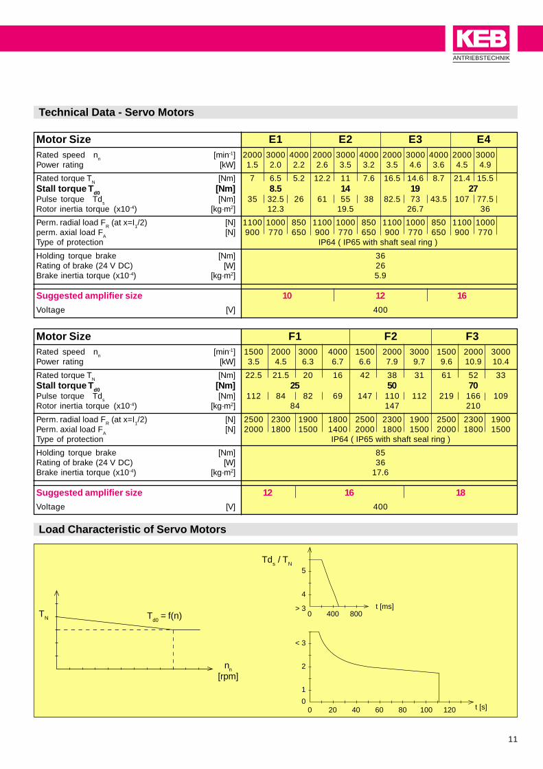
Technical Data - Servo Motors
Motor Size E1 E2 E3 E4Rated speed nn [min-1] 2000 3000 4000 2000 3000 4000 2000 3000 4000 2000 3000Power rating [kW] 1.5 2.0 2.2 2.6 3.5 3.2 3.5 4.6 3.6 4.5 4.9
Rated torque TN
[Nm] 7 6.5 5.2 12.2 11 7.6 16.5 14.6 8.7 21.4 15.5Stall torque Td0 [Nm] 8.5 14 19 27Pulse torque Tds [Nm] 35 32.5 26 61 55 38 82.5 73 43.5 107 77.5Rotor inertia torque (x10-4) [kg·m2] 12.3 19.5 26.7 36
Perm. radial load FR (at x=I1/2) [N] 1100 1000 850 1100 1000 850 1100 1000 850 1100 1000perm. axial load F
A[N] 900 770 650 900 770 650 900 770 650 900 770
Type of protection IP64 ( IP65 with shaft seal ring )
Holding torque brake [Nm] 36Rating of brake (24 V DC) [W] 26Brake inertia torque (x10-4) [kg·m2] 5.9
Suggested amplifier size 10 12 16
Voltage [V] 400
Motor Size F1 F2 F3Rated speed nn [min-1] 1500 2000 3000 4000 1500 2000 3000 1500 2000 3000Power rating [kW] 3.5 4.5 6.3 6.7 6.6 7.9 9.7 9.6 10.9 10.4
Rated torque TN
[Nm] 22.5 21.5 20 16 42 38 31 61 52 33Stall torque Td0 [Nm] 25 50 70Pulse torque Tds [Nm] 112 84 82 69 147 110 112 219 166 109Rotor inertia torque (x10-4) [kg·m2] 84 147 210
Perm. radial load FR (at x=I1/2) [N] 2500 2300 1900 1800 2500 2300 1900 2500 2300 1900Perm. axial load F
A[N] 2000 1800 1500 1400 2000 1800 1500 2000 1800 1500
Type of protection IP64 ( IP65 with shaft seal ring )
Holding torque brake [Nm] 85Rating of brake (24 V DC) [W] 36Brake inertia torque (x10-4) [kg·m2] 17.6
Suggested amplifier size 12 16 18
Voltage [V] 400
Load Characteristic of Servo Motors
Td0
= f(n)TN
nn
[rpm]
Tds / T
N
12
c
l b
øa2
k1
S2
S
a1
a3dk6
e f
k
k2
m p
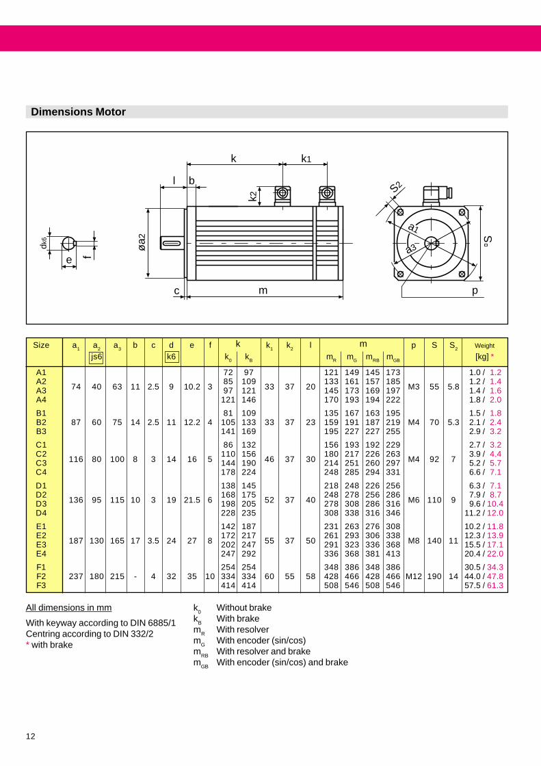
Dimensions Motor
k0
Without brakek
BWith brake
mR
With resolverm
GWith encoder (sin/cos)
mRB
With resolver and brakem
GBWith encoder (sin/cos) and brake
All dimensions in mm
With keyway according to DIN 6885/1Centring according to DIN 332/2* with brake
Size a1 a2 a3 b c d e f k1 k2 l p S S2 Weight
js6 k6 k0 kB mR mG mRB mGB [kg] *
A1 72 97 121 149 145 173 1.0 / 1.2A2 85 109 133 161 157 185 1.2 / 1.4A3 74 40 63 11 2.5 9 10.2 3 97 121 33 37 20 145 173 169 197 M3 55 5.8 1.4 / 1.6A4 121 146 170 193 194 222 1.8 / 2.0
B1 81 109 135 167 163 195 1.5 / 1.8B2 87 60 75 14 2.5 11 12.2 4 105 133 33 37 23 159 191 187 219 M4 70 5.3 2.1 / 2.4B3 141 169 195 227 227 255 2.9 / 3.2
C1 86 132 156 193 192 229 2.7 / 3.2C2 110 156 180 217 226 263 3.9 / 4.4C3 116 80 100 8 3 14 16 5 144 190 46 37 30 214 251 260 297 M4 92 7 5.2 / 5.7C4 178 224 248 285 294 331 6.6 / 7.1
D1 138 145 218 248 226 256 6.3 / 7.1D2 168 175 248 278 256 286 7.9 / 8.7D3 136 95 115 10 3 19 21.5 6 198 205 52 37 40 278 308 286 316 M6 110 9 9.6 / 10.4D4 228 235 308 338 316 346 11.2 / 12.0
E1 142 187 231 263 276 308 10.2 / 11.8E2 172 217 261 293 306 338 12.3 / 13.9E3 187 130 165 17 3.5 24 27 8 202 247 55 37 50 291 323 336 368 M8 140 11 15.5 / 17.1E4 247 292 336 368 381 413 20.4 / 22.0
F1 254 254 348 386 348 386 30.5 / 34.3F2 237 180 215 - 4 32 35 10 334 334 60 55 58 428 466 428 466 M12 190 14 44.0 / 47.8F3 414 414 508 546 508 546 57.5 / 61.3
mk
COMBIVERT S4ANTRIEBSTECHNIK
13
Fiber optic Operator00.F4.010-A009
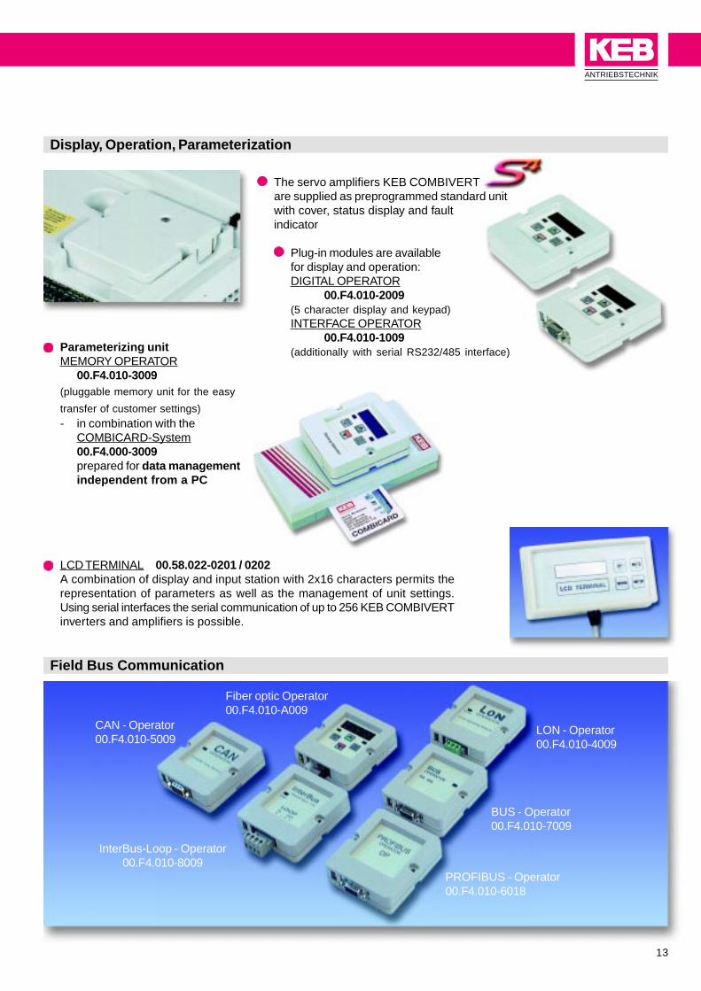
LCD TERMINAL 00.58.022-0201 / 0202A combination of display and input station with 2x16 characters permits therepresentation of parameters as well as the management of unit settings.Using serial interfaces the serial communication of up to 256 KEB COMBIVERTinverters and amplifiers is possible.
Display, Operation, Parameterization
The servo amplifiers KEB COMBIVERTare supplied as preprogrammed standard unitwith cover, status display and faultindicator
Plug-in modules are availablefor display and operation:DIGITAL OPERATOR
00.F4.010-2009(5 character display and keypad)INTERFACE OPERATOR
00.F4.010-1009(additionally with serial RS232/485 interface)Parameterizing unit
MEMORY OPERATOR00.F4.010-3009
(pluggable memory unit for the easy
transfer of customer settings)- in combination with the
COMBICARD-System00.F4.000-3009prepared for data managementindependent from a PC
Field Bus Communication
BUS - Operator00.F4.010-7009
LON - Operator00.F4.010-4009
CAN - Operator00.F4.010-5009
PROFIBUS - Operator00.F4.010-6018
InterBus-Loop - Operator00.F4.010-8009

14
Motor cable
Encoder cable resolver
Radio Interference Suppression Filter
Optionally the servo amplifiers KEB COMBIVERT are available with integrated radio interference suppression. Thefilters comply with EN 55011/B taken into account conducted interferences. This permits the use of the units in domesticand industrial districts. Besides the filters the radio interference suppression also incorporates effective grounding platesproviding a large contact surface for the shield connection.
Technical data radio interference suppression filter KEB COMBIVERT S4Unit size Voltage Filter designation Rated current Discharge
[V] [A] current [mA]
03* 230 09.E4.T60-0001 20 12
05* 230 09.E4.T60-0001 20 12
07* 400 10.E4.T60-1001 8 15
10* 400 10.E4.T60-1001 8 15
12* 400 14.E4.T60-1001 20 30
16* 400 16.E4.T60-1001 50 30
18 400 18.E4.T60-1001 70 30
Shielded motor cables preassembled with connector on one end for motors upto size E, which incorporate separately shielded wires two each for thetemperature sensor and the brake.
Shielded resolver cables preassemled with plug connector on one end for themotor and Submin 15-pin connector for the direct connection to the servoamplifier, encoder interface 1/ X4, on the other end.
5 m 00.S4.019-000510 m 00.S4.019-001015 m 00.S4.019-001520 m 00.S4.019-00205 m 00.S4.119-0005
10 m 00.S4.119-001015 m 00.S4.119-001520 m 00.S4.119-0020
Preassembled Cables
MotorsizesA1-E1
MotorsizesE2-E4
5 m 00.S4.109-000510 m 00.S4.109-001015 m 00.S4.109-001520 m 00.S4.109-0020
Allsizes
* available with built-on filter

COMBIVERT S4ANTRIEBSTECHNIK
15
D
EØ
F
B
C
A
Pulse Braking Resistor
To take up short-time generatoric load pulses compact back mounted brakingresistors are available designed with space savings in mind. The braking resistorsare fitted with a thermal contact and are layed out for total on time of 5 %.
Separation platefor servo amplifier03, 05, 07, 10, 12
Temperature sensorconnection to [OH OH]
Braking resistorconnection to [PA PB]
Braking Resistor for Continuous Load
Size Part Number Braking PN (5% ED)
Resistor [Ω] [W]
03,05,07,10 12.F4.D50-4200 82 700
12 14.F4.E50-4200 60 1200
16 16.F4.G50-4200 25 3200
Braking TimeED =
Total Cycle Time
To take up larger energies use either the braking resistors designed for continuous load or the feedback module KEBCOMBIVERT R4 which is available on request.
Amplifier Part Number RB PD PN A B C D E Ø FSize 6 s / 120 s [Dimensions in mm]
[Ohm] [W] [kW]
03, 05 09.BR.100-1100 100 82 1.5 160 28 40 10 145 6
07, 10 10.BR.100-6270 270 130 2.1 300 28 40 10 285 6
12 12.BR.100-6150 150 230 3.7 300 28 80 10 285 6
16 16.BR.110-6423 42 820 13.1 470 63 96 32 455 16,5
18 18.BR.226-6203 20 1700 27.4 625 270 120 176/240 526 6

16
For the adaption of speed and torque different gearbox solutions are available in the classical design of inline helicalgear, spur worm gear, shaftmounted helical gear and helical bevel gear.With the low backlash planetary gearboxes of the series Alpha, available in two performance variants
LP = 12/15‘ SP = 6/8 ‘, you get an optimal combination for dynamic tasks.
Panetary Gearboxes
high reliability
high efficiency > 95%
maximum accuracy
thermal length compensation
Motor nN MN LP 050 LP 070 LP 090 LP 120 LP 155 SP 060 SP 075 SP 100 SP 140 SP 180 SP 210Size
rpm Nm
A1.SM. 6000 0.34 5…10 5…25 4…40 4…100
A2.SM. 6000 0.5 5 5…10 4…28 4…50
A3.SM. 6000 0.65 5 5…10 4…20 4…16
A4.SM. 6000 1.0 5…10 4…16 4…40
B1.SM. 6000 0.65 5 5…10 5…25 4…40 4…100
B2.SM. 6000 1.5 5…10 5…25 5…50 4…10 4…40 4…100
B3.SM. 6000 2.3 5 5…10 5…25 4…7 4…20 4…50
C1.SM. 3000 1.0 5…10 5…25 5…50 4…10 4…40 4…100
C2.SM. 3000 1.8 5 5…10 5…25 4…7 4…20 4…50
C3.SM. 3000 2.8 5…10 5…25 4…5 4…10 4…28
C4.SM. 3000 4.8 5…10 4…7 4…20
D1.SM. 3000 3.4 5 5…10 5…25 4…7 4…20 28…50 70…100
D2.SM. 3000 5.6 5 5…10 5…25 4…7 7…16 20…28 40…70
D3.SM. 3000 7.5 5 5…10 5…,25 4…5 7…10 16…28 40…50
D4.SM. 3000 9.6 5…10 5…10 4…5 7…10 16…20 28…50
E1.SM. 3000 8.4 5…10 5…10 4…10 16…20 28…40 50…70
E2.SM. 3000 12.0 5 5…10 4…7 10…16 20…28 40…50
E3.SM. 3000 15.5 5 5…10 4…7 4…10 16…28 40
E4.SM. 3000 20.5 5 5…10 4…5 7…10 16…28 28…40
Assignment Motor Size / Gear Ratio

COMBIVERT S4ANTRIEBSTECHNIK
17
L3 L2
D6
D2 k
6
D4
D1
D3 k
6
L4
L1
L6
D8
D54x90°
D94x90°
L5
L7
Technical Data LP Gearbox
Technical Data Gearbox LP 050 LP 070 LP 090 LP 120 LP 155
Max. acceleration torque T2B
[Nm] 11.5 32 80 200 400
Nominal torque T2N
[Nm] 5.2 15 35 90 170
Max. radial load Frmax
[N] 650 1450 2400 4600 7500
Max. axial load Famax
[N] 700 1550 1900 4000 6000
Torsional backlash jt [arcmin] 12-15 12 - 15 12 - 15 12 - 15 12 - 15
Torsional rigidity Ct.21 [Nm/arcmin] 0.9 3.3 9 24 55
Max. input speed mmax
[min-1] 8000 6000 6000 4800 3600
Nominal input speed mnom
[min-1] 4000 3000 3000 2400 1800
Output shaft dshaft
* lshaft [mm] 12 x 18 16 x 28 22 x 36 32 x 58 40 x 82
Size D1 D2h6
D3k6
D4 D5 D6 L1 L2 L3 L4 L5 L6 L7
[mm] Ø 1-stage 2-stage
LP 050 50 35 12 44 M4 17 75 91 18 6,5 14 13.5 4 20
LP 070 70 52 16 62 M5 25 104 124 28 8 25 18 5 22
LP 090 90 68 22 80 M6 40 126 152.5 36 10 32 24.5 6 28
LP 120 120 90 32 108 M8 50 172 204.5 58 12 50 35 10 38
LP 155 155 120 40 140 M10 62 219.5 250 82 15 70 43 12 45

18
D5
D1
L5
D4
L3 L2
D6
D2 g
6
D3 k
6
L4
L1
L6
Technical Data SP Gearbox
Technical Data Gearbox SP 060 SP 075 SP 100 SP 140 SP 180 SP 210
Max. acceleration torque T2B
[Nm] 40 100 250 500 1100 1900
Nominal torque T2N
[Nm] 25 70 170 360 1050 1500
Max. radial load Frmax
[N] 2600 3800 6000 9000 14000 18000
Max. axial load Famax
[N] 1300 1900 3000 4500 7000 9000
Torsional backlash jt [arcmin] < 6 < 6 < 4 < 4 < 4 < 4
Torsional rigidity Ct.21 [Nm/arcmin] 3 8 24 45 144 400
Max. input speed mmax
[min-1] 6000 6000 4500 4000 3500 3000
Nominal input speed mnom
[min-1] 4000 3000 2500 2000 2000 1500
Output shaft dshaft
* lshaft [mm] 16 x 28 22 x 36 32 x 58 40 x 82 55 x 82 75 x 105
Size D1 D2h6
D3k6
D4 D5 D6 L1 L2 L3 L4 L5 L6
[mm] Ø 1st. 2st.
SP 060 62 60 16 68 5.5 30 129 149 28 20 25 18 5
SP 075 76 70 22 85 6.6 38 156 182.5 36 20 32 24.5 6
SP 100 101 90 32 120 9 55 202 234.5 58 30 50 35 10
SP 140 141 130 40 165 11 70 256.5 296.5 82 30 70 43 12
SP 180 182 160 55 215 13 90 297 315.5 82 30 70 59 16
SP 210 212 180 75 250 17 120 350 397 105 38 90 79.5 20

COMBIVERT S4ANTRIEBSTECHNIK
19
COMBIVIS
19
KEB Drive Systems

Karl E. Brinkmann GmbHFörsterweg 36 - 38 • D - 32683 BarntrupTelefon 0 52 63 / 4 01 - 0 • Telefax 4 01 - 116Internet: www.keb.de • E-mail: [email protected] ©
KE
B
00.
00.0
00-5
1S4
10
/200
0