combined shock and vibration isolation through the self
TRANSCRIPT

Northrop Grumman Newport News Proprietary/Sensitive Information - This document contains information proprietary or sensitive to Northrop Grumman Newport News and is not to be disclosed to, copied by, or used in any manner by others without the prior
express, written permission of Northrop Grumman Newport News.
Combined Shock and Vibration Isolation Through the Self-Powered, Semi-Active Control
of a Magnetorheological Damper in Parallel with an Air Spring
E. Troy Tanner
Dissertation submitted to the faculty of the Virginia Polytechnic Institute and State University in partial fulfillment of the requirements for the degree of
Doctor of Philosophy in
Mechanical Engineering
Daniel J. Inman, Co-Chairman Mehdi Ahmadian, Co-Chairman
Harry H. Robertshaw Donald J. Leo
Douglas K. Lindner
November 7, 2003 Blacksburg, Virginia
Keywords: Shock Isolation, Vibration Isolation, Magnetorheological Damper 2003, E. Troy Tanner

Northrop Grumman Newport News Proprietary/Sensitive Information - This document contains information proprietary or sensitive to Northrop Grumman Newport News and is not to be disclosed to, copied by, or used in any manner by others without the prior
express, written permission of Northrop Grumman Newport News.
Combined Shock and Vibration Isolation Through the Self-Powered, Semi-Active Control
of a Magnetorheological Damper in Parallel with an Air Spring
E. Troy Tanner
Abstract
Combining shock and vibration isolation into a single isolation system package is
explored through the use of an air spring in parallel with a controlled magnetorheological
fluid damper. The benefits of combining shock and vibration isolation into a single
package is discussed. Modeling and control issues are investigated and test and
simulation results are discussed. It is shown that this hybrid isolation system provides
significantly increased performance over current state-of-the-art passive systems. Also
explored is the feasibility of scavenging and storing ambient shipboard vibration energy
for use in powering the isolation system.
To date the literature has not adequately explored the direct design of a combined
shock and vibration isolation system. As shock and vibration isolation are typically
conflicting goals, the traditional approach has been to design separate shock and vibration
isolation systems and operate them in parallel. This approach invariably leads to
compromises in terms of the performance of both systems. Additionally, while
considerable research has been performed on magnetorheological fluids and devices
based on these fluids, there has been little research performed on the use of these fluids in
devices that are subjected to high velocities such as the velocity seen by a ship exposed to
underwater near-miss explosive events. Also missing from the literature is any research
involving the scavenging and storage of ambient shipboard vibration energy. While the
focus of this work is on the use of this scavenged energy to power the subject isolation
system, many other uses for this energy can be envisioned.

Northrop Grumman Newport News Proprietary/Sensitive Information - This document contains information proprietary or sensitive to Northrop Grumman Newport News and is not to be disclosed to, copied by, or used in any manner by others without the prior
express, written permission of Northrop Grumman Newport News.
iii
Experimental and analytical results from this research clearly show the
advantages of this hybrid isolation system. Drop tests show that inputs as great as 167
g’s were reduced to 3.42 g’s above mount at 1.11 inches of deflection using a Velocity
Feedback controller suggested by the author. When contrasted with typical test results
with similar inputs, the subject isolation system achieved reductions in above mount
accelerations of 300% and reductions in mount deflections of 200% over current state-of-
the-art passive shipboard isolation systems. Furthermore, simulations using a validated
model of the isolation system suggest that this performance improvement can be achieved
in multi-degree-of-freedom isolation systems as well. It was shown that above mount
accelerations in the vertical and athwartship directions could be effectively limited to a
predefined value, while achieving the absolute minimum mount defections, using an
Acceleration Limiting Bang-Bang controller suggested by the author. Further
experimentation suggests that the subject isolation system could be entirely self-powered
from scavenged ambient shipboard vibration energy. An experiment using an energy
scavenging and storage system consisting of a Piezoelectric Stack Generator and a bank
of ultracapacitors showed that enough energy could be harvested to power the isolation
system though several shock events.

Northrop Grumman Newport News Proprietary/Sensitive Information - This document contains information proprietary or sensitive to Northrop Grumman Newport News and is not to be disclosed to, copied by, or used in any manner by others without the prior
express, written permission of Northrop Grumman Newport News.
iv
Dedication
I would like to dedicate this dissertation to my mother Marlene Tanner and my
grandfather, Albert Ford. My mother taught me the value of hard work and to this day
she is the hardest working person I know. During my younger years she struggled
working several jobs to make sure that our family had what we needed. My grandfather
taught me what it was to be a decent human being. He was the kindest, most virtuous
man I have ever known and he would do anything for anyone in a time of need. I only
hope that at the end of my life I can look back and say that my mother and grandfather
would have been proud of me.

Northrop Grumman Newport News Proprietary/Sensitive Information - This document contains information proprietary or sensitive to Northrop Grumman Newport News and is not to be disclosed to, copied by, or used in any manner by others without the prior
express, written permission of Northrop Grumman Newport News.
v
Acknowledgements
I would first like to thank my wife, Kelly, and kids, Riley, Braden and Collin, for
putting up with my addiction to education which lead to my pursuit of this degree. They
have had to make many sacrifices over the years while I have been working and going to
school and I truly appreciate their support.
Special thanks are in order for my two co-advisors, Dr. Dan Inman and Dr. Mehdi
Ahmadian. Drs. Inman and Ahmadian have shown great patience and support while
dealing with the difficulties and frustrations of advising an off-campus student working in
industry. I could not ask for a better pair to guide me through the overwhelming task of
getting to this point in my studies. I would also like to thank Dr. Harry Robertshaw, Dr.
Don Leo and Dr. Doug Lindner for serving on my committee. Furthermore, Drs.
Robertshaw and Leo deserve a special thanks for teaching controls to an old guy with no
controls background. Whoever said you can't teach an old dog new tricks?
I would also like to thank Bob Marshall, my Supervisor at Northrop Grumman
Newport News, for all of his help in pushing my company to realize the potential, and
ultimately funding, this research. Bob never gave up no matter how dim the prospects
became. Bob was also very supportive of my pursuing an advanced degree and helped
me considerably in working out the logistics of taking classes, exams, and trips to
Virginia Tech by working around my schedule.
Finally I would like to thank Doug Huebner of Newport News for teaching me
much of what I needed to know about electronics and the practical aspects of
implementing control and data acquisition systems. Doug’s knowledge of electronics and
engineering in general is no less than amazing. There is not a single subject in
engineering that Doug is not familiar with. I am convinced that if Doug had not chosen
engineering as a career he would have made a great teacher.
Northrop Grumman Newport News Proprietary/Sensitive Information - This document contains information proprietary or sensitive to Northrop Grumman Newport News and is not to be disclosed to, copied by, or used in any manner by others without the prior
express, written permission of Northrop Grumman Newport News.
vi
Contents
1.0 INTRODUCTION ....................................................................................................1
1.1 Overview ....................................................................................................................1
1.2 Research Approach ....................................................................................................3
2.0 LITERATURE REVIEW .......................................................................................6
2.1 Overview ....................................................................................................................6
2.2 Magnetorheological or Electrorheological Fluids and their Applications .................7
2.2.1 Fluid Properties and Modeling ...................................................................................7
2.2.2 Application to Control of Civil Structures ...............................................................13
2.2.3 Helicopter Lag Mode Damping ...............................................................................22
2.2.4 Automotive Applications .........................................................................................22
2.2.5 Gun Recoil Control Applications .............................................................................25
2.2.6 Other Applications of MR/ER Fluid Devices ..........................................................26
2.3 Combined Shock and Vibration Isolation ................................................................26
2.4 Self-Powered Isolation Systems ..............................................................................27
2.5 Active and Semiactive Mounts ................................................................................27
2.6 Power Scavenging ....................................................................................................29
2.6.1 Scavenging Footfall Energy .....................................................................................29
2.6.2 Scavenging Vibration Energy ..................................................................................30
2.6.3 Other Power Scavenging Applications ....................................................................32
2.7 Summary ..................................................................................................................34
3.0 SHOCK AND VIBRATION ISOLATION THEORY .......................................36
3.1 Vibration Isolation Theory .......................................................................................36

Northrop Grumman Newport News Proprietary/Sensitive Information - This document contains information proprietary or sensitive to Northrop Grumman Newport News and is not to be disclosed to, copied by, or used in any manner by others without the prior
express, written permission of Northrop Grumman Newport News.
vii
3.1.1 The Direct Excitation Problem ................................................................................37
3.1.2 The Base Excitation Problem ...................................................................................40
3.2 Shock Isolation Theory ............................................................................................45
3.3 Combined Shock and Vibration Isolation ................................................................47
4.0 SHIP SHOCK ANALYSIS AND TESTING .......................................................48
4.1 Ship Shock Inputs ....................................................................................................48
4.2 Navy Shock Test Machines .....................................................................................50
5.0 MR/AIR MOUNT DEVELOPMENT AND MODELING ................................54
5.1 The Air Spring as a Shock Isolator ..........................................................................54
5.2 Developing the System Model .................................................................................58
5.3 Control Algorithm Investigaton ...............................................................................63
5.3.1 Lyapunov Controller ................................................................................................64
5.3.2 Modulated Homogeneous Friction Controller .........................................................65
5.3.3 Decentralized Bang-Bang Controller .......................................................................66
5.3.4 Linear Quadratic Regulator Optimal Controller ......................................................67
5.3.5 Controller Performance Evaluation .........................................................................70
5.3.6 Velocity Feedback Controller ..................................................................................74
5.3.7 Acceleration Limiting Bang-Bang Controller .........................................................77
6.0 MR/AIR MOUNT TESTING AND VALIDATION ...........................................79
6.1 Shock Isolation Performance ...................................................................................79
6.2 Drop Test Fixture Design..........................................................................................79
6.3 Drop Test Procedure ................................................................................................82
6.4 Drop Test Data Acquisition and Control Instrumentation .......................................84

Northrop Grumman Newport News Proprietary/Sensitive Information - This document contains information proprietary or sensitive to Northrop Grumman Newport News and is not to be disclosed to, copied by, or used in any manner by others without the prior
express, written permission of Northrop Grumman Newport News.
viii
6.5 Drop Test Results .....................................................................................................89
6.6 Model Validation .....................................................................................................98
6.7 Acceleration Limiting Bang-Bang Controller Performance ..................................101
6.8 Controller Performance Comparison .....................................................................104
6.9 MRAM Performance Case Studies.........................................................................109
6.9.1 Equipment Level Isolation Performance ................................................................110
6.9.2 Equipment Raft Isolation Performance...................................................................113
6.9.3 Deck Isolation Performance....................................................................................115
6.10 Vibration Isolation Performance.............................................................................121
6.11 Chapter Summary ..................................................................................................122
7.0 MRAM MULTI-DEGREE-OF-FREEDOM PERFORMANCE ....................124
7.1 Multi-Degree-of-Freedom System Modeling ........................................................124
7.2 MDOF Control Algorithms ....................................................................................130
7.2.1 MDOF Skyhook Controller ...................................................................................131
7.2.2 MDOF Velocity Feedback Controller ...................................................................132
7.2.3 MDOF Acceleration Bang-Bang Controller ..........................................................132
7.3 MDOF Simulation Results .....................................................................................134
7.4 Chapter Summary ..................................................................................................141
8.0 POWER SCAVENGING SYSTEM DEVELOPMENT ...................................143
8.1 Introduction ............................................................................................................143
8.2 The Moving Magnet Linear Generator ..................................................................143
8.3 The Piezoelectric Stack Generator .........................................................................146
8.4 The Storage of Scavenged Energy .........................................................................152

Northrop Grumman Newport News Proprietary/Sensitive Information - This document contains information proprietary or sensitive to Northrop Grumman Newport News and is not to be disclosed to, copied by, or used in any manner by others without the prior
express, written permission of Northrop Grumman Newport News.
ix
8.5 Analysis of the Ultracapacitor Stack ......................................................................155
8.6 Empirical Analysis of the Piezoelectric Stack Generator ......................................160
8.7 Chapter Summary ..................................................................................................170
9.0 CONCLUSION ....................................................................................................172
9.1 Summary ................................................................................................................172
9.2 Future Work ...........................................................................................................174
10.0 APPENDICES ......................................................................................................175
Appendix A. MATLAB/Simulink Simulation Models .……. ....................................175 Appendix B. Drop Test Fixture Drawings .…….............................................................200 11.0 REFERENCES ......................................................................................................205
Northrop Grumman Newport News Proprietary/Sensitive Information - This document contains information proprietary or sensitive to Northrop Grumman Newport News and is not to be disclosed to, copied by, or used in any manner by others without the prior
express, written permission of Northrop Grumman Newport News.
x
List of Figures
Figure 3.1a. Illustration of Two Typical Vibration Isolation Problems (Base Excitation) ………………………………………………………..... 36 Figure 3.1b. Illustration of Two Typical Vibration Isolation Problems (Direct Excitation) ………………………………………………..……..... 36
Figure 3.2. Force Transmissibility (Direct Excitation) …...…………..…………….… 40 Figure 3.3. Displacement Transmissibility (Base Excitation) ………..…………….… 43 Figure 3.4. Force Transmissibility (Base Excitation) …...…………..…………..….… 45 Figure 3.5. Acceleration Transmissibility (Base Excitation) …..……..…………….… 46 Figure 4.1. UNDEX Bubble Development ……………….…………..…………….… 48 Figure 4.2. Typical Hull-Level Response to an UNDEX Event ……...…………….… 49 Figure 4.3. Typical Deck-Level Response to an UNDEX Event …...………………… 50 Figure 4.4. Lightweight Shock Machine ……………………….……..…………….… 51 Figure 4.5. Medium Weight Shock Machine ………………………....…………….… 51 Figure 4.6. Floating Shock Platform …………………….…………..…………..….… 52 Figure 4.7. FSP During an UNDEX Test …………………….……..……………....… 52 Figure 5.1. Absolute Acceleration Response of Equipment on a 2 Hz Air Spring ….... 55
Figure 5.2. Relative Displacement of a 2 Hz Air Spring ……………..…………….… 56
Figure 5.3. The Effect of Adding Passive Damping to an Air Spring (Displacement) .. 57
Figure 5.4. The Effect of Adding Passive Damping to an Air Spring (Acceleration) ... 57
Figure 5.5. SDOF System Model …………………………...………..…………….…. 59
Figure 5.6. System Free-Body Diagram ………………………………...………..…… 59 Figure 5.7. LQR Optimal Control System Block Diagram ………..………..…...….… 68 Figure 5.8. Scaled Base Input Used in Algorithm Comparison Simulations..…...….… 71

Northrop Grumman Newport News Proprietary/Sensitive Information - This document contains information proprietary or sensitive to Northrop Grumman Newport News and is not to be disclosed to, copied by, or used in any manner by others without the prior
express, written permission of Northrop Grumman Newport News.
xi
Figure 5.9. Controller Acceleration Response Comparison ………..……..…..…...…. 72 Figure 5.10. Controller Displacement Response Comparison …..…………...…....…… 72 Figure 5.11. Displacement and Acceleration Peak Comparison …..………...…....…… 73 Figure 5.12. Velocity Feedback Control System Block Diagram .…………...…....…… 75
Figure 5.13. Comparison of Energy Loss per Cycle ………………….………..……… 76
Figure 6.1. Drop Test Fixture Assembly……………………...………………….…… 81 Figure 6.2. Drop Test Operation ………………...………..………………………..… 82
Figure 6.3. MR/Air Mount Technology Demonstrator …………….………………… 83 Figure 6.4. MR Damper Pair Detail …………….……………………………………. 83 Figure 6.5. dSpace Data Acquisition and Control Set-up …………………………… 85 Figure 6.6. dSpace Connector Panel Layout ……………………………………...…. 85 Figure 6.7. Drop Test Signal Conditioning Equipment ………………………………. 87 Figure 6.8. MR Damper Current Drivers and Power Supplies ………………………. 88 Figure 6.9. Acceleration Response to 1 in. Drop with LQR Optimal Controller….….. 91
Figure 6.10. Displacement Response to 1 in. Drop with LQR Optimal Controller ….... 91 Figure 6.11. Acceleration Response to 1 in. Drop with Velocity Feedback Controller .. 92
Figure 6.12. Displacement Response to 1 in. Drop with Velocity Feedback Controller . 92 Figure 6.13. Damping Force for 1 in. Drop with LQR Optimal Controller ……….…... 93
Figure 6.14. Damping Force for 1 in. Drop with Velocity Feedback Controller …….... 93 Figure 6.15. Acceleration Response to 2 in. Drop with LQR Optimal Controller .…..... 94
Figure 6.16. Displacement Response to 2 in. Drop with LQR Optimal Controller …..... 94 Figure 6.17. Acceleration Response to 2 in. Drop with Velocity Feedback Controller .. 95 Figure 6.18. Displacement Response to 2 in. Drop with Velocity Feedback Controller . 95

Northrop Grumman Newport News Proprietary/Sensitive Information - This document contains information proprietary or sensitive to Northrop Grumman Newport News and is not to be disclosed to, copied by, or used in any manner by others without the prior
express, written permission of Northrop Grumman Newport News.
xii
Figure 6.19. Damping Force for 2 in. Drop with LQR Optimal Controller ………......... 96
Figure 6.20. Damping Force for 2 in. Drop with Velocity Feedback Controller ……..... 96 Figure 6.21. Comparison of FSP Inputs to MR/Air Mount Test Input ………….…....... 98
Figure 6.22. Experimental and Analytical Data Comparison (Relative Displacement) .. 99 Figure 6.23. Experimental and Analytical Data Comparison (Relative Velocity) .…… 100 Figure 6.24. Experimental and Analytical Data Comparison (Absolute Acceleration) . 100 Figure 6.25. Above Mount Acceleration with Acceleration Limiting Controller …...... 103 Figure 6.26. Mount Deflection with Acceleration Limiting Controller ………..…....... 104 Figure 6.27. Comparison of Mount Relative Displacements …………………..…....... 106 Figure 6.28. Comparison of Above Mount Absolute Acceleration ……………..…..... 106 Figure 6.29. Controller Damping Force Comparison……………………………......... 107 Figure 6.30. Damping Force and Control Voltage with LQR Controller …………...... 107 Figure 6.31. Damping Force and Control Voltage with Velocity Feedback Controller. 108 Figure 6.32. Damping Force and Control Voltage with Bang-Bang Controller …….... 108 Figure 6.33. Input Used in Peformance Case Studies ……………………...…..…....... 110 Figure 6.34. Case Study 1 (Relative Displacement, FSP DSF Input) ……...……......... 111 Figure 6.35. Case Study 1 (Absolute Acceleration, FSP DSF Input) …..…….....…..... 111 Figure 6.36. Case Study 1 (Relative Displacement, FSP Inner Bottom Input) ……..... 112 Figure 6.37. Case Study 1 (Absolute Acceleration, FSP Inner Bottom Input) ……...... 112 Figure 6.38. Damping Force versus Displacement Behavior ………………..……….. 114 Figure 6.39. Case Study 2 & 3 (Relative Displacement, 15g Controller, FSP DSF Input) …………........ 117 Figure 6.40. Case Study 2 & 3 (Absolute Acceleration, 15g Controller, FSP DSF Input) …...…...…....... 117
Northrop Grumman Newport News Proprietary/Sensitive Information - This document contains information proprietary or sensitive to Northrop Grumman Newport News and is not to be disclosed to, copied by, or used in any manner by others without the prior
express, written permission of Northrop Grumman Newport News.
xiii
Figure 6.41. Case Study 2 & 3 (Relative Displacement, 5g Controller, FSP DSF Input) ……………...... 118 Figure 6.42. Case Study 2 & 3 (Absolute Acceleration, 5g Controller, FSP DSF Input) ………….…...... 118 Figure 6.43. Case Study 2 & 3 (Relative Displacement, 15g Controller, FSP IB Input) ……………….... 119 Figure 6.44. Case Study 2 & 3 (Absolute Acceleration, 15g Controller, FSP IB Input) ……….…..…..... 119 Figure 6.45. Case Study 2 & 3 (Relative Displacement, 7g Controller, FSP IB Input) ………….……..... 120 Figure 6.46. Case Study 2 & 3 (Absolute Acceleration, 7g Controller, FSP IB Input) ………….……..... 120 Figure 6.47. Force Transmissibility Comparison ……………..…………………….... 121 Figure 7.1. 3DOF System Model …………………………………………..……....... 125
Figure 7.2. Spring Deflection Due to Cabinet Rotation ……………….…..…...…..... 126 Figure 7.3. 14Hz FSP Input Used in the Simulations …………………...…...…….... 135
Figure 7.4. Athwartship Response (Relative Displacement) ………………….…….. 135 Figure 7.5. Vertical Response (Relative Displacement) …………………..……........ 136
Figure 7.6. Athwartship Response (Absolute Acceleration) …………………..…….. 136 Figure 7.7. Vertical Response (Absolute Acceleration) ……………………..…........ 137 Figure 7.8. Rotational Response About the CG …………………...……………….... 137
Figure 7.9. Response Peaks Comparison …………………….………………..…….. 138 Figure 7.10. Voltage Output from Controllers …………….………………..……........ 138
Figure 7.11. 3DOF Cabinet Response (Air Spring Only versus MRAM) ………...….. 139 Figure 7.12. 3DOF Cabinet Response (Passive Mount versus MRAM) ……….….......139 Figure 8.1. Moving Magnet Linear Generator ……………………………..……....... 144

Northrop Grumman Newport News Proprietary/Sensitive Information - This document contains information proprietary or sensitive to Northrop Grumman Newport News and is not to be disclosed to, copied by, or used in any manner by others without the prior
express, written permission of Northrop Grumman Newport News.
xiv
Figure 8.2. Behavior of Piezoceramic with Applied Voltage ………….…………..... 147 Figure 8.3. Behavior of Piezoceramic with Applied Force ……………...…...…….... 147
Figure 8.4. Piezogenerator Relationships ……………………………………..…….. 148 Figure 8.5. Piezoelectric Stack Generator …………………………..………….......... 151
Figure 8.6. Schematic of Charging Circuit …………...…………………......……..... 155 Figure 8.7. Ultracapacitor Charging Circuit ………………………….……...…….... 156 Figure 8.8. Charging Curve for the Ultracapacitor Stack ………………………….... 157
Figure 8.9. Discharging Curve for the Ultracapacitor Stack …………...…..….…….. 159 Figure 8.10. Capacitor Voltage as a Function of Constant Discharge Power ……….... 159
Figure 8.11. Kinetic Ceramics Prototype Piezoelectric Stack Generator …….………. 160 Figure 8.12. Piezoelectric Stack Generator in the MTS Load Frame ……………..….. 161 Figure 8.13. Data Acquisition Equipment for the Power Scavenging Experiment …... 162
Figure 8.14. Schematic of the Equipment used in the Power Scavenging Experiment . 163 Figure 8.15. Schematic of the Charging Circuit for the PSG Test ................................. 163 Figure 8.16. Model Used to Determine Force in the PSG…………………………….. 164 Figure 8.17. Output Voltage versus Frequency for the Piezoelectric Stack Generator . 165
Figure 8.18. Output Voltage versus Force for the Piezoelectric Stack Generator …..... 166 Figure 8.19. Charging Curve for the Ultracapacitor with PSG as the Charge Source ... 168
Figure 8.20. Force – Deflection Plot for the PSG …………………… .……...……..... 169 Figure 8.21. Load – Capacitance Behavior of the PSG …………………….……….... 170

Northrop Grumman Newport News Proprietary/Sensitive Information - This document contains information proprietary or sensitive to Northrop Grumman Newport News and is not to be disclosed to, copied by, or used in any manner by others without the prior
express, written permission of Northrop Grumman Newport News.
xv
List of Tables
Table 5.1. Parameters for the MR Damper Model …………………..…...………..…... 61
Table 6.1. Drop Test Response Comparison ……………………………...………….... 97 Table 7.1. Skyhook Control Algorithm ……………….……………..…...…………... 131
Table 7.2. MDOF Skyhook Logic Table ………..………………………...……..….... 131 Table 8.1. RMS AC Voltage (Volts) from PSG into a 5 MΩ LLoad ….…..…….…...... 167
Table 8.2. RMS AC Voltage (Volts) from PSG into a 10 kΩ LLoad …….…..……....... 167

Northrop Grumman Newport News Proprietary/Sensitive Information - This document contains information proprietary or sensitive to Northrop Grumman Newport News and is not to be disclosed to, copied by, or used in any manner by others without the prior
express, written permission of Northrop Grumman Newport News.
1
Chapter 1 Introduction
1.1 Overview
A classic problem in isolation system design is the design of a single isolator that
can perform equally well as both a shock and a vibration isolator. This problem arises
due to the fact that a good vibration isolator tends to be a poor shock isolator and vice
versa. Most attempts to solve the combined isolation problem with a passive device
quickly lead to frustration. This is certainly the case in shipboard isolation applications
where many different inputs are often present simultaneously. The typical approach to
solving the shipboard isolation problem involves utilizing separate passive isolators for
shock and vibration. This inevitably leads to modifying vibration isolators to survive
shock inputs and/or modifying shock isolators to perform adequately as vibration
isolators. Inevitably the result of using this approach is less than optimal isolation
performance.
When combined shock and vibration isolation is a design goal a semi-active
isolation system becomes attractive. Semi-active isolation systems can be designed to
simultaneously isolate for the combined and varying inputs that are present in shipboard
applications. The physical advantages to combining shock and vibration isolation into a
single package are obvious. A single combined isolation system replaces at least two
separate systems and therefore reduces weight and increases available volume. This is
particularly important in submarine applications where space is limited. Furthermore,
with varying and diverse inputs, a combined semi-active isolation system can be designed
to perform better than separate passive shock and vibration isolation systems operating in
parallel. With careful design procedures the result can be nearly mathematically optimal
isolation performance.

Northrop Grumman Newport News Proprietary/Sensitive Information - This document contains information proprietary or sensitive to Northrop Grumman Newport News and is not to be disclosed to, copied by, or used in any manner by others without the prior
express, written permission of Northrop Grumman Newport News.
2
For shipboard applications the ideal isolation system would provide effective
acoustic, vibration, and shock isolation from a variety of inputs such as underwater
explosions, wave slap, impact, etc. Thus a "soft" isolator with a natural frequency no
greater than say 2 Hz is desired that can survive various shock inputs. An ideal vibration
isolator that meets this design criteria is an air spring. Air springs have a low natural
frequency and are excellent shock isolators during the initial shock transient.
Unfortunately, they tend to behave poorly as shipboard shock isolators due to the fact that
shock events, such as underwater explosions (UNDEX), tend to drive the air spring into
resonance following the initial transient. An air spring, being an inherently low
frequency and lightly damped device, tends to undergo large deflections at resonance.
Clearly this is undesirable in shipboard applications due to ever present tight rattle space
requirements.
An ideal combined isolator would be an air spring that could provide large,
variable damping forces on demand during a shock event. Producing large, variable
damping forces is an ideal application for a magnetorheological (MR) fluid damper.
Therefore, combining an air spring with a parallel-mounted MR damper would provide
an ideal combined isolation system provided the damping force can be applied and varied
rapidly enough to attenuate the shock input and simultaneously meet rattle space
requirements.
A further motivation for investigating the MR damper as an isolator element is the
current desire to introduce Commercial Off-the-Shelf (COTS) equipment into the
shipboard environment. COTS equipment is typically categorized as either Industrialized
COTS equipment or Commercial-Grade COTS equipment. Industrialized COTS
equipment typically requires a 15g maximum above mount environment and
Commercial-Grade COTS equipment typically requires a 7 to 8g maximum above mount
environment. Furthermore, it is anticipated that in the near future COTS equipment
manufacturers will be seeking to achieve above mount environments as low as 5 g’s.
These environments are very difficult to achieve with passive isolators, particularly if
stringent vibration isolation specifications need also be met simultaneously. However,

Northrop Grumman Newport News Proprietary/Sensitive Information - This document contains information proprietary or sensitive to Northrop Grumman Newport News and is not to be disclosed to, copied by, or used in any manner by others without the prior
express, written permission of Northrop Grumman Newport News.
3
numerical studies and experimental data have shown that both shock and vibration
specifications for all grades of COTS equipment can be easily met by using an isolation
system consisting of an MR damper in parallel with an air spring. Furthermore, with
current refresh rates for electronic equipment now approaching 18 months, the weight of
the equipment, and its center-of-gravity is very likely to change with each refresh.
Therefore, a re-evaluation and/or replacement of the isolation system could conceivably
be required every 18 months. This is a very costly and time-consuming process. A semi-
active isolation system can be designed to automatically adapt to variations in equipment
mass and center-of-gravity as new equipment is introduced.
One drawback to any semi-active system is the need for a power source, with its
associated cabling, as well as additional cabling to connect to an external controller. This
problem is recognized and has stalled many attempts to use semi-active devices in
shipboard isolation systems. MR devices are attractive in that they have low power
requirements, are inherently stable, and in the absence of power they still behave as
passive dampers. The later is particularly attractive as a failsafe feature as there is no
guarantee that power will be available to the isolation system during battle conditions. A
benefit of having low power requirements is that it may be possible to create a self-
powered device. This could conceivably be accomplished by scavenging vibration
energy and storing it to drive the MR damper/control system during a shock event.
Having a self-powered, self-contained, combined shock and vibration isolator would be
especially attractive as it would eliminate the need for external power sources and
external controller connections.
1.2 Research Approach
The following outlines the approach taken for this research effort. First a simple
single degree-of-freedom (SDOF) model of the isolation system was developed. This
allowed a survey of control methodologies to be performed by simulation of the
algorithms that have been successfully implemented in the past for controlling the MR

Northrop Grumman Newport News Proprietary/Sensitive Information - This document contains information proprietary or sensitive to Northrop Grumman Newport News and is not to be disclosed to, copied by, or used in any manner by others without the prior
express, written permission of Northrop Grumman Newport News.
4
damper. This was done to determine the optimum control algorithm for use with ship
shock inputs from the currently accepted control algorithms for the MR damper. The
results of the simulations suggested that Linear Quadratic Regulator (LQR) optimal
control provided the best performance of the algorithms tested. LQR was then used as an
example for comparison for the other controllers that were developed. In an attempt to
minimize the number of sensors required to implement LQR a controller was developed
that utilized velocity feedback. This controller was designed to provide an energy loss
per cycle that was as close as possible to being equivalent to that obtained with LQR
control. This approach was driven by the nature of a ship-shock input due to an
underwater near-miss explosion. These events tend to be fairly low cycle thus the
maximum energy loss per cycle is desired in a ship-shock isolation system.
The LQR and velocity feedback controllers were then tested experimentally in a
custom designed drop test machine. The design of the drop test machine was part of this
effort. The drop test subjected the isolation system to a true base excitation shock event
that was similar in acceleration magnitude to that seen in a Floating Shock Platform
(FSP) test which is a standard Navy test platform. The FSP is essentially a barge to
which can be fitted deck simulators of varying frequencies. The excitation is provided by
underwater high-explosive charges at various stand-off distances. The test data suggested
that the isolation system was very effective at isolating some very significant shock
inputs with both of the control algorithms. The test data was also used to validate the
single degree-of-freedom model. Very good correlation was achieved between the test
and simulation data.
In an attempt to determine whether it would be feasible to power the isolation
system using scavenged ambient shipboard vibration energy, the energy requirements for
powering the device through a single shock event was determined. While in a practical
application it would be desirable to be able to power the system through several shock
events, for this test the design goal was set for powering the isolation system through one
event. This was done with the realization that the approach could be scaled up to
scavenge and store more energy fairly easily. For this study it was assumed that the

Northrop Grumman Newport News Proprietary/Sensitive Information - This document contains information proprietary or sensitive to Northrop Grumman Newport News and is not to be disclosed to, copied by, or used in any manner by others without the prior
express, written permission of Northrop Grumman Newport News.
5
energy to be scavenged would come from a vibrating deck. Therefore, it was necessary
to determine the amplitude and frequency of the available driving force. This was done
analytically and verified through simulation. A survey of candidate power scavenging
devices was then conducted and it was determined that a Piezoelectric Stack Generator
(PSG) appeared to be an ideal device for the small amplitude, relatively high force inputs
available to drive the device. Although several means exist for storing the scavenged
energy, a stack of ultracapacitors was selected for this test. The PSG and the
ultracapacitor stack was then tested experimentally both separately and as a system.
Comparison was made with the expected performance from simulation and reasonable
agreement was achieved.
From insight into the ship shock problem another controller was developed that
limited the above mount acceleration to a preset maximum. Simulation suggested that
this controller was ideal for use in ship shock applications as it simultaneously limited the
above mount acceleration while minimizing the mount deflection. The later is desirable
as ships typically have very tight rattle space requirements.
Using the validated SDOF model a three degree-of-freedom (3DOF) model of a
generic equipment cabinet isolated with the subject isolation system was developed. In
shipboard applications a 3DOF model is of sufficient fidelity to determine the response of
an isolated piece of equipment since the vast majority of the input energy occurs in the
vertical and athwartship (port-starboard) directions. Very little energy is input in the
fore-aft direction. This model allowed an examination of the isolation system
performance due to simultaneous multi-axis inputs and included the effects of rotation of
the isolated equipment. The simulation results with the 3DOF model suggested that the
acceleration limiting controller was very effective in simultaneously limiting above
mount acceleration in both axes, as well as minimizing mount deflections and cabinet
rotation.

Northrop Grumman Newport News Proprietary/Sensitive Information - This document contains information proprietary or sensitive to Northrop Grumman Newport News and is not to be disclosed to, copied by, or used in any manner by others without the prior
express, written permission of Northrop Grumman Newport News.
6
Chapter 2
Literature Review
2.1 Overview
A comprehensive review of the available literature was conducted to determine
the uniqueness of the subject areas of research. The specific areas of interest that were
investigated were: (1) magnetorheological or electrorheological fluid devices and their
applications, (2) the design of isolation systems that are specifically designed for
combined shock and vibration isolation, (3) active and semiactive mounts, (4) self-
powered isolation systems, and (5) the scavenging of ambient energy. The following
approach was taken to complete the search. First an internet search was performed to
find any available papers that were accessible via the internet or included contact
information. The papers were then downloaded form the internet or the author was
contacted to obtain a copy of the paper. The initial papers obtained, as well as the
reference list from each of these papers, was then used to compile a master reference list.
Next a search on the above topics was conducted using the ISI Web of Science service.
All of the hits using this approach were added to the master list. Finally any contacts
familiar to the author that happened to be working in this general area of research were
contacted in an effort to obtain any papers they may have published. All of these papers
were compiled in the master list.
The original master list contained 274 papers. At this point it became clear that
the resources necessary to retrieve the remaining papers was beyond the capabilities of
those available to the author. Thankfully, Dr. Inman offered to have an on-campus
student track down as many of the papers on the master list as possible. Approximately
half of the papers could not be found due to their age or the cost of obtaining a copy. The
papers that were retrieved were further culled by eliminating any papers whose topics

Northrop Grumman Newport News Proprietary/Sensitive Information - This document contains information proprietary or sensitive to Northrop Grumman Newport News and is not to be disclosed to, copied by, or used in any manner by others without the prior
express, written permission of Northrop Grumman Newport News.
7
were not similar to the subject work. The result was a compilation of 91 papers whose
content is summarized in the next sections.
2.2 Magnetorheological or Electrorheological Fluids and their
Applications
For the purpose of this review, magnetorheological and electrorheological fluids
were lumped together due to the similarity in their mechanical properties. Any paper that
discussed MR and/or ER fluids was considered acceptable for review. The MR and ER
fluid papers were separated into the following sub-topics.
2.2.1 Fluid Properties and Modeling
Many of the papers whose topics involved MR and ER fluids were concerned
with the mechanical properties of the fluids and/or modeling of these properties. 28 of
the papers reviewed were devoted to the discussion or modeling of the properties of these
unique fluids. The following is a review of the literature that explored MR or ER fluid
properties and their modeling.
Ashour, Rogers and Kordonsky [1] discussed the basic properties of MR fluids
and their potential applications in vibration control problems. The complete process from
the manufacture of the fluid to its application in a cross stepper exercise machine was
discussed. The manufacture of the fluid in a high-speed bead mill was shown to produce
a high quality MR fluid. The characterization of the resulting fluid was discussed and the
increase of the apparent viscosity with the magnetic field strength was shown to be as
high as two orders of magnitude with moderate magnetic fields. The importance of the
MR throttle valve in MR devices was discussed and it was shown that the greatest
increase in apparent viscosity occurs when the flow direction of the MR fluid is normal to

Northrop Grumman Newport News Proprietary/Sensitive Information - This document contains information proprietary or sensitive to Northrop Grumman Newport News and is not to be disclosed to, copied by, or used in any manner by others without the prior
express, written permission of Northrop Grumman Newport News.
8
the magnetic field direction. As an application example, a conventional damper in a
commercial cross stepper exercise machine was retrofitted with an external throttle valve
and the hydraulic fluid was replaced with MR fluid. It was shown that the resistance of
the stroke of the foot pedals could be easily adjusted by varying the current to the coil in
the throttle valve. Bossis, Lemaire, Volkova and Clercx [2] looked at two models for
predicting the yield stress in MR and ER fluids.
Carlson, Catanzarite, and St. Clair [3] discussed the history of ER and MR fluids
mentioning that the first paper on ER fluids was published in 1949 and the first patent
was issued in 1947, both to Willis M. Winslow. Also mentioned was that the first papers
on MR fluids were written in 1948 and the first patent was issued in 1951, both to Jacob
Rabinow of the U.S. National Bureau of Standards. Several advantages of MR fluids
over ER fluids were pointed out. The two basic modes of operation for MR devices were
shown to be fixed poles (valve mode) or relatively moving poles (direct-shear mode). It
was further shown that to achieve comparable performance an ER fluid device requires
an active fluid volume that is 100-1000 times as large as that of an MR device. However,
it was shown that both devices would have similar power requirements, the problem
being that ER devices require high voltage at low current while MR devices require
higher current at low voltage. Three examples of commercially available MR fluid
devices were discussed: A MR Fluid Linear Damper for use in vehicle seat suspensions, a
MR Fluid Rotary Brake for use in aerobic exercise equipment, and an MR Fluid
Vibration Damper that can be used as a controllable dashpot.
Chang and Roschke [4] explored the development of a multi-layer perceptron
neural network model for the MR damper. It was shown that the model satisfactorily
represented dynamic behavior of the MR damper and therefore represents an adequate
alternative to the typical characterization models that consist of a system of non-linear
differential equations. Chu, Lee, and Ahn [5] explored the effect of changes in squeeze
flow behavior of ER fluids as applied electric field, volume concentration of silica
particles, viscosity of the carrier medium and water content in the silica was varied.

Northrop Grumman Newport News Proprietary/Sensitive Information - This document contains information proprietary or sensitive to Northrop Grumman Newport News and is not to be disclosed to, copied by, or used in any manner by others without the prior
express, written permission of Northrop Grumman Newport News.
9
Felt, Hagenbuchle, Liu and Richard [6] investigated the rheological behavior of
an MR fluid. It was shown that exposure of MR fluids to a magnetic field eventually
leads to non-Newtonian rheology, i.e., the occurrence of yield stress and shear thinning.
The dependence of apparent viscosity of the fluids on shear rate, field strength, volume
fraction of ferrous particles and diameter of the ferrous particles was explored. It was
shown that the dynamic yield stress increases in proportion to both the volume fraction
and particle size of the ferrous particles. In addition, it was shown that the shear stress in
the fluid is proportional to the square of the applied field. Furthermore, it was shown that
the rheology of MR fluids is very similar to the rheology of ER fluids. It was suggested
that the commonly used Bingham model gives an insufficient rheological description of
the MR fluid as it does not account for the effect of shear thinning.
Gamota and Filisko [7] explored the response of an ER fluid consisting of
alumino-silicate particles in paraffin oil to sinusoidally oscillating shear strains ranging in
frequency from 10 to 50 Hz. It was shown that the response of the fluid can be divided
into three distinct regions; pre-yield, yield and post-yield. Furthermore, it was shown that
the material behaves as a viscoelastic material in the pre-yield region, a viscoelastic-
plastic material in the yield region, and a plastic material in the post-yield region. These
modes are dependent on the applied electric field strength, strain amplitude and strain
frequency. It was determined that the energy dissipated by the ER material is
proportional to the strain raised to the second power in the pre-yield region, varies
between the strain raised to the second power and raised to the first power in the yield
region, and is proportional to the strain in the post yield region. A model for the ER
material was proposed consisting of a Zener element in series with a Coulomb and a
viscous element that describes the general behavior of the material as it changes from
viscoelastic to viscoeleastic-plastic. It was shown that as the electric field increased both
the ER fluid’s viscous and elastic components increase. Thus, the material has increased
its energy dissipating and energy absorbing capability.
Gorodkin, Lukianovich and Kordonski [8] investigated the modeling of the
pressure-flowrate characteristics of an MR throttle valve in which the hydraulic

Northrop Grumman Newport News Proprietary/Sensitive Information - This document contains information proprietary or sensitive to Northrop Grumman Newport News and is not to be disclosed to, copied by, or used in any manner by others without the prior
express, written permission of Northrop Grumman Newport News.
10
resistance characteristics of the valve are determined as a function of the Reynolds and
Hedstrom numbers. It was shown that the hydraulic characteristics of the valve predicted
by the Hedstrom technique accurately describes the characteristics of the valve. This was
validated by comparison to experimental data. A procedure for prediction of the valve
parameters necessary for damper design was suggested.
Jolly, Carlson and Munoz [9] explored the development of a quasi-static, one-
dimensional model that accurately described the mechanical and magnetic properties of
MR fluids and elastomers. The model needed to be fit to experimental magnetic
induction curves by adjusting a parameter that accounts for the un-modeled magnetic
interactions between neighboring particle chains. It was shown that these interactions
decrease with decreasing particle volume fraction. Once fit to the experimental data the
model was shown to be in relatively good agreement with published yield stress data for
MR fluids as well as pre-yield data taken on MR elastomers.
Kamath and Wereley [10] discussed a nonlinear dynamic model that effectively
described the electrorheological behavior of an ER fluid in terms of shear stress versus
shear strain. The model combined a three-parameter fluid element and a viscous fluid
element to accurately describe the shear flow behavior in the pre-yield and post-yield
regimes, respectively. To accurately describe the behavior through the yield point a
nonlinear combination of the linear shear flow mechanisms was utilized.
Kamath, Hurt and Wereley [11] discussed the development and validation of a
model that described the rheological behavior of an ER damper. The model was based on
an idealized nonlinear Bingham plastic shear flow mechanism. This mechanism predicts
that in a typical annular valve three annular flow regions develop as a function of local
shear stress. In the central region between the two electrodes, the so-called plug region,
the local shear stress is less that the yield stress and the fluid behaves as a rigid solid. In
the other two regions near the electrodes the local shear stress exceeds the yield stress
and the material flows. It was shown that the damping behavior of an ER damper is
strongly coupled with the behavior in the plug region. For a constant force, as the applied

Northrop Grumman Newport News Proprietary/Sensitive Information - This document contains information proprietary or sensitive to Northrop Grumman Newport News and is not to be disclosed to, copied by, or used in any manner by others without the prior
express, written permission of Northrop Grumman Newport News.
11
field increases, the plug thickness and the equivalent viscous damping increase as well.
For a constant applied field, as the force increases, the plug thickness and the equivalent
viscous damping both decrease.
Kordonsky [12] discussed the modeling of an MR fluid valve (Here called a
magnetorheological converter). The model takes into account the behavior of the
magnetic field producing inductor. Also discussed is a concept for a MR actuator as well
as the use of MR fluids as the working medium in seals.
Li, Chen, and Yeo [13] investigated the mechanical properties of MR fluids in the
pre-yield region. The viscoelastic properties were measured with a parallel-plate strain-
controlled rheometer. Two experiments were performed; a strain-amplitude sweep test
and a frequency sweep test. The strain-amplitude sweep test varied the strain amplitude
from 0.0001 to 0.001 at a fixed driving frequency of 10 Hz. The frequency sweep test
varied the driving frequency from 1 Hz to 100 Hz at a constant strain amplitude of 0.001.
The results showed that the both the storage modulus and the loss modulus increase with
increasing frequency while both decrease with an increase in strain amplitude. It was
also shown that an increase in magnetic field increases the storage modulus and loss
modulus and an increase in volume fraction of ferrous particles leads to an increase in
storage modulus.
Pang, Kamath and Wereley [14] discussed four models for describing the
hysteresis behavior of a Lord Rheonetics SD-1000-2 MR damper. The four models
discussed were: (1) nonlinear, Bingham plastic model, (2) nonlinear, biviscous model, (3)
nonlinear, hysteretic biviscous model, and (4) nonlinear, viscoelastic-plastic model. It
was shown that any of the models could predict the damper behavior adequately enough
to estimate energy dissipation or damping. It was suggested that the nonlinear,
viscoelastic-plastic model is superior to the other models for simulation because it is
piecewise smooth in velocity. The other three models are only piecewise continuous in
velocity. All of the models represent the force vs. displacement behavior of the damper
equally well.

Northrop Grumman Newport News Proprietary/Sensitive Information - This document contains information proprietary or sensitive to Northrop Grumman Newport News and is not to be disclosed to, copied by, or used in any manner by others without the prior
express, written permission of Northrop Grumman Newport News.
12
In the survey paper [15] Parthasarathy and Klingenberg discussed the current state
of modeling of ER fluid behavior. Sims, Peel, Stanway, Johnson and Bullough [16]
discussed the development of a model for an ER damper and its experimental
verification. The model consisted of a spring, mass and a damper connected in series.
The spring stiffness is based upon the bulk modulus of the ER fluid and the mass is
determined from the fluid density. The damping characteristics were described by a non-
dimensional, Bingham plastic function.
Sims, Stanway, Peel, Bullough and Johnson [17] discussed a control algorithm
that effectively linearizes the response of an ER damper to mimic the response of a
viscous damper using a proportional feedback control strategy. The result is the
equivalent of a viscous damper with a continuously variable damping coefficient. It was
shown experimentally that the slope of the force-velocity characteristics can be specified
and modified through a change in a gain term in the controller. The effectiveness of the
algorithm was shown at frequencies up to 5 Hz. Spencer, Dyke, Sain and Carlson [18]
discussed the development and validation of the Modified Bouc-Wen model of the MR
damper. The model was shown to accurately predict the force-displacement and force-
velocity behavior of a Lord MR damper. A survey paper [19] by Stanway, Sproston and
El-Wahed discussed the current (circa 1995) state of the use of ER fluids in vibration
control.
Timko, Zentko, Zentkova, M., Koneracka, Kellnerova, Zentkova, A., Stepan and
Barbora [20] discussed the effect of external magnetic field, velocity of flow and
concentration of magnetic particles on the rheological properties of mineral oil-based MR
fluids. It was shown that the apparent increase in the viscosity of the fluid increased with
increasing external magnetic field and increasing concentration of ferrous particles.
Furthermore, it was shown that at higher flow velocities the change of viscosity became
smaller. It was suggested that this was due to breakup of the chain structure formed by
the ferrous particles in the MR fluid.

Northrop Grumman Newport News Proprietary/Sensitive Information - This document contains information proprietary or sensitive to Northrop Grumman Newport News and is not to be disclosed to, copied by, or used in any manner by others without the prior
express, written permission of Northrop Grumman Newport News.
13
Weiss, Carlson and Nixon [21] investigated the transition area between elastic and
viscous behavior in ER and MR fluids. It was shown that the storage modulus for an MR
fluid is several orders of magnitude greater than that of an ER fluid, and is in the range of
common viscoelastic solids. Experiments showed that both MR and ER fluids yield at a
strain level of less than 1%. It was suggested that this behavior may hinder the use of
either fluid in applications that require stability in pre-yield properties. The authors felt
that future R&D efforts should be focus on increasing the yield of these fluids to higher
strain levels. In [22], Wereley and Pang discussed the nondimensional analysis of ER
and MR dampers using approximate parallel plate models. However, the accuracy of the
suggested models was not discussed.
2.2.2 Application to Control of Civil Structures
In terms of applications of MR and ER fluids, the vast majority of the published
work has involved the use of these fluids in structural response control of civil structures.
31 of the papers reviewed were devoted to this topic. Of particular interest appears to be
work involving earthquake hazard mitigation. Much of the civil structure work has been
performed by Bill Spencer at Notre Dame and later by his former graduate student
Shirley Dyke at the University of Washington.
Dyke and Spencer [23] investigated four different semiactive control algorithms
for the MR damper. The algorithms considered were control based on Lyapunov stability
theory, decentralized bang-bang control, modulated homogeneous friction and clipped
optimal control. The clipped optimal controller is essentially a linear optimal controller
that provides an optimal force value. A force feedback loop provides a measure of the
actual damping force which is then compared to the optimal control force. Based on this
comparison the voltage to the MR damper is varied to provide as near as possible the
optimal control force. The force feedback loop uses readily available accelerometers as
sensors. The performance of the various controllers was compared through the
simulation of the response of a 3-story structure with an MR damper connected between

Northrop Grumman Newport News Proprietary/Sensitive Information - This document contains information proprietary or sensitive to Northrop Grumman Newport News and is not to be disclosed to, copied by, or used in any manner by others without the prior
express, written permission of Northrop Grumman Newport News.
14
ground and the first story. The input for the simulations was the N-S component of the El
Centro earthquake data. As a control, two additional cases were considered, one being a
constant 0V being applied to the current driver and the other being a constant 2.25V
being applied to the current driver. This corresponds to the minimum and maximum
damping forces that can be generated by the MR damper. It was shown that all of the
algorithms performed noticeably better than the passive controllers in some way. The
largest reduction in the maximum acceleration was achieved with the decentralized bang-
bang controller. The largest reduction in third floor displacement and peak interstory
displacement was achieved with the clipped optimal controller. The paper also discusses
the Modified Bouc-Wen model of the MR damper, although it is not mentioned by that
name.
In [24], Dyke and Spencer continue the work of [23] by applying the clipped
optimal control algorithm to a five-story structure. The paper also discusses the Modified
Bouc-Wen model of the MR damper. In the experiment the dampers were placed
between the first floor and ground as well as the first and second stories. It was shown
that this damper placement using the clipped optimal control algorithm resulted in
significant reductions in floor accelerations while simultaneously reducing interstory
displacements. The inputs to the structure were data from the El Centro earthquake at
three different magnitudes. The semiactive approach achieved a 22%, 28% and 32%
reduction in the peak absolute acceleration over the best passive case while
simultaneously achieving large reductions in the interstory displacements.
In [25], Dyke continued the studies begun in [23] and [24] and expands the
simulation to the control of seismically excited 20-story building. The clipped optimal
control algorithm is again employed to control a total of 30 dampers that were applied to
control the structure. In addition to the dampers, the control system employed 36 sensors
and the controller had 40 states. Four inputs were considered including the El Centro
earthquake considered in the previous papers as well as the Hachinohe, Kobe and
Northridge earthquakes. It was shown that the control system achieved significant
reductions in all structural responses for all of the four earthquake excitations. Maximum

Northrop Grumman Newport News Proprietary/Sensitive Information - This document contains information proprietary or sensitive to Northrop Grumman Newport News and is not to be disclosed to, copied by, or used in any manner by others without the prior
express, written permission of Northrop Grumman Newport News.
15
relative displacements were reduced by 21.6-55.8%, maximum normalized drift was
reduced by 36.4-55.0%, maximum accelerations were reduced by 22.8-50.0% and base
shear was reduced by 34.4-55.3% as compared to the uncontrolled values.
Dyke, Spencer, Quast, Kaspari and Sain [26] discussed the use of acceleration
feedback control strategies based on H2/LQG control design techniques to control the
structural response of a three-story test structure using an active mass driver (AMD)
mounted at the top of the structure. It was shown that under broadband excitation the
AMD controller was able to achieve an 80% reduction in RMS acceleration responses as
well as a significant response reduction in all three modes of the system. Furthermore,
when excited by an earthquake disturbance, the reduction of the peak top floor
acceleration was 65%.
In [27], Dyke, Spencer, Sain and Carlson extended the work performed in [26]
which explored the effectiveness of the clipped optimal controller for controlling an MR
damper mounted in a 3-story test structure. Two optimal controllers were considered.
Controller A placed a heavy weighing on the third floor relative displacement. Controller
B placed a heavy weighting on the third floor acceleration. As a control two passive
cases were also considered. Passive off implied 0V was applied to the current driver of
the MR dampers. Passive on implied 2.25V was applied to the current driver of the MR
damper which corresponded to saturation of the magnetorheological effect. It was shown
experimentally that when subjected to the N-S component of the El Centro earthquake
Controller A achieved a 24.3% reduction in the peak third floor displacement and a
29.1% reduction in the maximum interstory displacement over the best passive case.
Controller B achieved a 33.3% reduction in the peak third floor relative displacement
over the best passive case although an increase in the maximum floor accelerations was
also seen.
Dyke, Spencer, Sain and Carlson [28] explored the modified Bouc-Wen model of
the MR damper as well as evaluated the performance of the MR damper and clipped
optimal control algorithm for controlling the response of a scaled three-story building

Northrop Grumman Newport News Proprietary/Sensitive Information - This document contains information proprietary or sensitive to Northrop Grumman Newport News and is not to be disclosed to, copied by, or used in any manner by others without the prior
express, written permission of Northrop Grumman Newport News.
16
model. It was shown that the performance of the semi-active clipped optimal controller
surpassed that of an active controller while requiring a small fraction of the power.
Dyke, Spencer, Sain, and Carlson [29] explored the efficiency of the MR damper in
conjunction with the clipped optimal control algorithm to control the structural response
of a scaled three-story structure. The structure was modeled and the model was
validated. Three versions of the clipped optimal controller were utilized. Controller A
placed a high weighting on the third-floor relative displacement. Controllers B and C
placed low and high weighting, respectively, on the third floor acceleration. It was
shown that the control system effectively reduced both the peak and RMS responses due
to a broad class of seismic excitations over that of the response using both passive-off
and passive-on control. All of the controllers achieved excellent results when compared
to the passive cases. In addition, it was shown that the semi-active control systems were
able to achieve these performance gains using smaller control forces than the passive-on
case.
Dyke, Spencer, Sain and Carlson [30] discussed the modified Bouc-Wen model of
the MR damper and its effectiveness at predicting the response of the MR damper. The
paper then explored the effectiveness of the clipped optimal control algorithm in reducing
the structural response of a scaled three-story structure model. It was shown that the
clipped optimal control strategy performed better than either the passive-off or passive-on
cases. Furthermore, the clipped optimal controller outperformed a simulated optimal
active controller, while requiring only a small fraction of the power of the active system.
In [31], Dyke, Spencer, Sain and Carlson present essentially the same information as in
[30].
Dyke, Yi and Carlson [32] experimentally explore the effectiveness of utilizing
shear mode MR dampers in conjunction with the clipped optimal control algorithm to
control a six-story test structure. The control system employs four shear mode MR
dampers which are claimed to produce a maximum force of 20kN (4500 lbf) each. It was
shown that the semi-active controller is capable of surpassing the performance of the
passive-on controller at the first two modes of vibration.

Northrop Grumman Newport News Proprietary/Sensitive Information - This document contains information proprietary or sensitive to Northrop Grumman Newport News and is not to be disclosed to, copied by, or used in any manner by others without the prior
express, written permission of Northrop Grumman Newport News.
17
Housner, Bergman, Caighey, Chassiakos, Claus, Masri, Skelton, Soong, Spencer
and Yao [33] present a survey paper that summarizes the current (circa 1997) state-of-
the-art in structural control of civil engineering structures. The history of MR fluid
devices is discussed from their discovery by Winslow (1947) to the current work by
Spencer, Dyke and Carlson. The clipped optimal controller is mentioned briefly, but no
technical information or performance characteristics are discussed.
Inaudi [34] discussed a control algorithm that makes the contact force between
sliding surfaces of a friction damper proportional to the absolute value of the prior local
peak of the damper displacement. This control logic results in a nonlinear force-
displacement behavior such that when the damper displacement is scaled by a constant,
the damper force is scaled by the same constant. The force-displacement hysteresis loops
of the closed-loop system are rectangular and the area (energy dissipation) are
proportional to the square of the damper displacement. This paper only discussed the
modeling and control of a friction damper in a model of a six-story structure with the
dampers installed as cross braces. No results that showed the effectiveness of the
dampers with the proposed algorithm were discussed.
Jansen and Dyke [35] explored three nonlinear control algorithms: (1) control
based on Lyapunov stability theory, (2) decentralized bang-bang control and (3) clipped
optimal control. A modified Bouc-Wen model of the shear mode dampers that were
utilized was developed. A numerical study of the response of a six-story structure
controlled with four shear mode MR dampers controlled using the above algorithms was
conducted. The test input was a scaled version of the N-S component of the El Centro
earthquake. Two of the dampers were mounted between the first floor and ground and
the other two were mounted between the first and second floors. Two versions of the
Lyapunov and clipped optimal controllers were investigated (Denoted A and B), but it is
not explained how these differ. As a control two passive controllers were also
considered; Passive-off and passive-on. Based on the numerical results it was shown that
all of the algorithms showed improvement over the best passive case. It was determined
that two of the controllers were most suitable for use with multiple MR dampers, the
Northrop Grumman Newport News Proprietary/Sensitive Information - This document contains information proprietary or sensitive to Northrop Grumman Newport News and is not to be disclosed to, copied by, or used in any manner by others without the prior
express, written permission of Northrop Grumman Newport News.
18
Lyapunov and clipped optimal controllers. The Lyapunov B controller was able to
achieve the largest reduction in maximum floor displacement. The largest reduction in
maximum interstory displacement and maximum absolute acceleration was achieved with
the clipped optimal controller B and A, respectively.
In [36], Jansen and Dyke essentially expanded the work performed in [35] by
adding the modulated homogeneous friction controller to the study. In addition, the
differences between the Lyapunov and clipped optimal A and B controllers is explained.
The two Lyapunov controllers have different QP matrices. The clipped optimal A
controller placed a moderate weighting on the relative displacements of all floors. The
clipped optimal B controller placed a higher weighing on the relative displacement of all
floors. The results were as in [35] with the exception of the added modulated
homogeneous friction controller which was shown to achieve a significant reduction in
displacements and drifts at the expense of increased accelerations.
Makris, Burton and Taylor [37] discussed the design, analysis and modeling of an
ER fluid damper developed for seismic response reduction in civil structures. A multi-
layer neural network was developed and trained with an efficient algorithm known as the
Dependence Identification Algorithm. It was shown that a neural network constructed
with the Dependence Identification Algorithm and combined with a standard Maxwell
model satisfactorily predicts the response of the damper with and without the presence of
an electric field.
Makris, Burton, Hill and Jordan [38] discussed the mechanical behavior of a
silicon oil based ER fluid and a damper that utilizes this fluid. The damper was designed
for the reduction of seismic response and vibration in civil structures. The damper
consisted of a cylinder and piston that pushed the ER fluid through an external annular
duct. The electric field was applied to the fluid flowing through this duct. It was shown
that the flow through the duct can be satisfactorily approximated with an elastic-
viscoplastic model based on Hagen-Poiseille flow theory. Furthermore, it was shown that
to have a significant contribution to the damper force from the ER effect, the flow rate

Northrop Grumman Newport News Proprietary/Sensitive Information - This document contains information proprietary or sensitive to Northrop Grumman Newport News and is not to be disclosed to, copied by, or used in any manner by others without the prior
express, written permission of Northrop Grumman Newport News.
19
across the duct must be kept relatively small. It was suggested that this can be achieved
by increasing the number of bypasses. This suggests that ER fluids may not be ideal for
shock applications where high flow rates can be anticipated.
Masri, Kumar and Ehrgott [39] discussed the modeling and control of an ER
damper for structural control applications. The model utilized was developed by fitting
Chebyshev polynomials to experimental ER damper force data. It was shown that the
damper model accurately predicts the damper behavior. The controller used appears to
be based on optimal control, but sufficient detail is not presented to follow the control
algorithm development. After determining an optimum damping force the controller uses
a force-voltage function to determine the voltage to be applied to the damper. This
controller was termed “pulse” control. It was suggested that the use of this controller
produces a favorable reduction in displacement and acceleration response, but the one
plot shown suggested only minimal performance improvement.
Quast, Sain, Spencer and Dyke [40] discussed digital control concepts and their
application to the acceleration feedback control of a three-story test structure. The
control force was provided by an active bracing system that utilized a hydraulic actuator.
The controller was implemented on a Texas Instruments TMS320C30 DSP chip at a
sampling rate of 1 kHz. Although the control strategy was not discussed in detail, it was
shown experimentally that the digital controller reduced the absolute accelerations of the
top two floors of the test structure by more than a factor of two.
Ramallo, Johnson and Spencer [41] discussed the use of sponge-type MR
dampers in a base isolation system for the seismic control of structures. A modified
clipped optimal control algorithm was used for control. When compared to the damper
operating in an optimal passive mode (which was determined experimentally), the
damper controlled with the modified clipped optimal control algorithm achieved
significant accelerations reductions over the entire range of earthquake intensities
considered.

Northrop Grumman Newport News Proprietary/Sensitive Information - This document contains information proprietary or sensitive to Northrop Grumman Newport News and is not to be disclosed to, copied by, or used in any manner by others without the prior
express, written permission of Northrop Grumman Newport News.
20
Sadek and Mohraz [42] discussed three semi-active control algorithms for
controlling variable dampers. The three algorithms discussed were: (1) Classic LQR
control, (2) A modified LQR algorithm that places a penalty on the absolute acceleration
of each DOF to place an additional emphasis on the structural accelerations, and (3) A
semi-active displacement-acceleration domain algorithm that changes the damping
coefficient based on the angle formed in the displacement-acceleration plane by the
absolute acceleration and the displacement. It was shown that variable dampers are
effective in reducing the responses in flexible structures, but not in rigid structures. The
best performance in terms of displacement and acceleration response was achieved with
the modified LQR algorithm. The other two algorithms achieved similar performance for
SDOF structures, but the displacement-acceleration domain algorithm was not effective
for MDOF structures.
Spencer and Sain [43] discussed the use of feedback control methods for the
response control of civil structures. The paper reviews the control implementations that
have already been incorporated in civil structures and discusses current research in the
area of structural control. No results or mathematical description of algorithms are
presented.
Spencer, Yang, Carlson and Sain [44] explored the development and validation of
a model for a 20-ton MR damper designed for seismic protection of civil structures. The
damper was designed and built by the Lord Corporation. Two models were considered;
an axisymetric model and a simpler parallel-plate model. It was shown that the simpler
parallel-plate model could accurately approximate the force-velocity behavior of the
damper. It was also shown that the controllable force range is inversely related to the gap
size.
In this survey paper [45] Symans and Constantinou compare passive, active, and
semi-active structural control systems in a general sense. Also included is a review of the
literature on semi-active structural control systems. Yang, Spencer, Carlson and Sain
[46] discussed the modeling of the Lord 20-ton prototype MR damper using the modified

Northrop Grumman Newport News Proprietary/Sensitive Information - This document contains information proprietary or sensitive to Northrop Grumman Newport News and is not to be disclosed to, copied by, or used in any manner by others without the prior
express, written permission of Northrop Grumman Newport News.
21
Bouc-Wen model. This damper was designed for full-scale implementation of MR
dampers in civil structures. Excellent agreement was shown between the model and
experimental data.
Yi and Dyke [47] explored the capabilities of ideal passive and active control
systems on response reduction of structures. The passive system considered was an ideal
passive damper. The ideal active system consisted of an ideal actuator using a H2/LQG
control algorithm. To evaluate the performance of the controllers, the structural response
of 1, 3, 6, 10 and 20-story buildings was determined. In all cases the base excitation was
white noise and the responses and control forces were recorded as RMS values. It was
shown that active control offers no advantage over passive systems for the SDOF
structure. However, as the number of degrees-of-freedom increased the performance of
the active system surpassed that of the passive system and the performance increase was
greater as the number of floors increased.
Yi, Dyke, Caicedo and Carlson [48, 49] discussed the results of a numerical study
to determine the effectiveness of utilizing shear mode MR dampers in conjunction with
the clipped optimal controller for seismic response reduction. This study used four
randomly placed MR dampers in a six-story structure. Each damper was capable of
producing 29 kN (6520 lb) of force. It was shown that this semi-active system achieved
excellent performance, surpassing a number of optimal passive systems, while using a
very small amount of power to do so. Yi, Dyke, Frech and Carlson [50] presented
essentially the same material as in [48, 49].
Yoshida and Dyke [51] discussed a control solution to the third generation
benchmark problem on structural control. This benchmark problem consisted of the
control of a seismically-excited, full-scale, nonlinear, 20-story building. The control
approach taken in this paper was the use of shear mode MR dampers that were controlled
using the clipped optimal control algorithm as well as a modified clipped optimal control
algorithm. The modified clipped optimal control algorithm assumed a linear relationship
between the force produced by the damper and voltage applied to the current driver. It

Northrop Grumman Newport News Proprietary/Sensitive Information - This document contains information proprietary or sensitive to Northrop Grumman Newport News and is not to be disclosed to, copied by, or used in any manner by others without the prior
express, written permission of Northrop Grumman Newport News.
22
was shown that both of the controllers provided performance that equaled, and in some
cases exceeded, the performance of an active system. Furthermore, it was shown that the
modified controller was significantly more effective at reducing structural accelerations,
while achieving nearly the same reduction in interstory drifts, as with the non-modified
controller.
2.2.3 Helicopter Lag Mode Damping
Marathe, Gandhi and Wang [52] investigated the use of a shear mode MR damper
for improving lag damping in helicopter rotor blades. A model of the MR damper is
incorporated into a mechanical model of the rotor. Two controllers were considered: An
on-off controller and a feedback linearization controller. The on-off controller attempts
to linearize the response of the nonlinear MR damper to approximate an equivalent linear
damper. The feedback linearization controller attempts to linearize the force output of
the nonlinear MR damper. It was shown that both controllers are effective in reducing
ground resonance and reducing periodic damper loads in forward flight.
It should be noted that additional work in the area of helicopter lag mode damping
has been performed by Norman Wereley at the University of Maryland, but none of Dr.
Wereley's papers on this subject were readily available.
2.2.4 Automotive Applications
A sizable amount of MR fluid research has been performed for the automotive
industry. However, due to the desire to protect proprietary material, it is difficult to find
much literature on automotive applications of MR fluids available to the general public.
What is clear is that MR damper-based suspension systems for automobiles have reached
the production phase (Witness the MR damper-based suspensions on the new Cadillac

Northrop Grumman Newport News Proprietary/Sensitive Information - This document contains information proprietary or sensitive to Northrop Grumman Newport News and is not to be disclosed to, copied by, or used in any manner by others without the prior
express, written permission of Northrop Grumman Newport News.
23
and Corvette). Reducing the cost of these systems will surely lead to their introductions
on lower priced vehicles. Being very research oriented, the fact that the auto industry is
paying this much attention to MR devices is a clear indication of the significant
performance increases that can be obtained with these devices.
Carter's [53] thesis explores the transient response characteristics of a Class 8
truck using passive and semactive dampers. The response was simulated using a four-
degree-of-freedom roll-plane model. Four different control policies were investigated
including on-off skyhook, continuous skyhook, on-off groundhook and a newly
developed method of fuzzy logic control. The results of the simulations show that
compared to passive dampers, semiactive dampers have minimal effect on improving the
vehicle body and tire transients due to forces or torques applied to the body. However,
for road inputs the semiactive dampers are able to provide a more favorable compromise
between the body and axle transient dynamics as compared to passive dampers.
Furthermore, it was shown that the fuzzy logic semiactive control policy is better able to
control body and axle dynamics than the more traditional semiactive policies that were
investigated.
Choi and Cheong [54] discussed the development and testing of a suspension
system consisting of an ER damper powered by a generator system consisting of a rack
and pinion gear to transform the linear motion of the damper into rotary motion which
was then amplified through additional gearing. The resulting rotary motion is then used
to drive a generator and the energy is stored in a battery to power the damper and control
circuitry. It was shown that this fairly complex system could generate enough power to
operate the ER damper-based suspension. Furthermore, it was shown that acceptable
vibration isolation could be achieved in terms of displacement transmissibility up to 2 Hz
when utilized in a quarter car model.
McLellan [55] discussed the development and testing of a digital controller for a
MR damper-based suspension system for a Class 8 truck. The controller used a skyhook
policy to control the MR dampers which were installed in the truck’s primary suspension

Northrop Grumman Newport News Proprietary/Sensitive Information - This document contains information proprietary or sensitive to Northrop Grumman Newport News and is not to be disclosed to, copied by, or used in any manner by others without the prior
express, written permission of Northrop Grumman Newport News.
24
system. The controller utilized accelerometers that were placed on the truck’s frame and
axle. The completed control system was tested with both random (on highway) and
impulse (speed bump) inputs. It was shown that the semiactively controlled MR dampers
do not offer any significant benefits in reducing the overall vibration levels at the frame
or axles. However, some benefit was realized with transient inputs (speed bumps).
Pare [56] discussed the development and testing of a semi-active suspension
system for a passenger vehicle that utilized MR dampers. To test the system a full-scale,
2DOF, 1/4 car test apparatus was designed and built. Three control schemes were
evaluated: (1) Skyhook control, (2) Groundhook control, and (3) Hybrid semiactive
control (essentially combining both skyhook and groundhook control). Skyhook control
was shown to be effective at isolating the motion of the sprung mass from the base
excitation at the expense of excessive un-sprung mass motion. Groundhook control was
shown to be effective at controlling the un-sprung mass motion at the expense of
excessive sprung mass motion. Hybrid semiactive control (essentially a linear
combination of skyhook and groundhook control) yielded a performance that essentially
took advantage of the benefits of both skyhook and groundhook control. Finally, the MR
dampers were installed in a Chevy Lumina in a constant voltage mode, i.e., the
controllers were not utilized in the actual test vehicle.
Simon [57] discussed the design and testing of a MR damper-based, semi-active
suspension system for a heavy truck. The dampers were controlled using a skyhook
control policy. The performance was evaluated with two different inputs. The first was a
transient input which was implemented by driving the truck over a speed bump at a
relatively low (5-7 MPH) speed. The second was a random input which was achieved by
driving the truck at 55 MPH on a straight and level highway. To determine the effective
performance benefit of the MR damper-based suspension, the response was compared to
the response with the stock suspension and passive-on and passive-off MR damper
suspensions. For the transient input, it was shown that the MR damper-based suspension
with the skyhook control policy showed a small change in vehicle body and wheel
dynamics as compared to the stock suspension. However, in terms of peak accelerations

Northrop Grumman Newport News Proprietary/Sensitive Information - This document contains information proprietary or sensitive to Northrop Grumman Newport News and is not to be disclosed to, copied by, or used in any manner by others without the prior
express, written permission of Northrop Grumman Newport News.
25
and displacements the MR suspension showed little performance improvement. For the
random input the MR damper-based suspension achieved a significant improvement in
performance over the stock suspension.
2.2.5 Gun Recoil Control Applications
The research on gun recoil control using MR dampers is the only work found that
looked at using MR dampers in extremely high velocity applications. As such, this work
represents the only work using MR dampers in systems that are subjected to the type of
velocities that are seen in shipboard shock isolation applications.
Ahmadian and Poyner [58] discussed the application of MR dampers for
controlling gun recoil dynamics. The development of a demonstrator consisting of a
single-shot 50 caliber BMG rifle and a prototype MR damper was discussed. It was
shown that the MR damper was very effective at reducing the recoil stroke of the gun at
the expense of significantly increased recoil forces. This work, and that in [59], is
significant in that it is the only known work on MR dampers subjected to very high
velocities. In this effort no control was performed. A constant voltage was applied to the
current drivers, which in turn supply the current to the dampers, and the resulting recoil
stroke and force were measured for varying input voltages.
Ahmadian, Appleton and Norris [59] explored the application of MR dampers for
controlling the dynamics of a fire out-of-battery (FOOB) recoil system for large guns
using a dynamic simulation of a 105mm cannon. The FOOB system works by pre-
accelerating the recoiling parts in the direction opposite to the recoil prior to ignition. It
was shown through simulation that while conventional hydraulic recoil dampers can be
designed and tuned to control FOOB as effectively as MR dampers, they cannot perform
well when firing faults are encountered. The results showed that MR dampers were able
to adapt to firing faults such as pre-fire, hang-fire and misfire and provided “soft-recoil”

Northrop Grumman Newport News Proprietary/Sensitive Information - This document contains information proprietary or sensitive to Northrop Grumman Newport News and is not to be disclosed to, copied by, or used in any manner by others without the prior
express, written permission of Northrop Grumman Newport News.
26
under all firing conditions. Further work will apply this concept to actual hardware in the
field.
2.2.6 Other Applications of MR/ER Fluid Devices
The following two papers did not fit into the categories established above for MR
and ER-based device applications, but are still significant and are therefore included in
this review.
Yalcintas and Dai [60] discussed the vibration control capabilities of MR and ER
adaptive beam structures (essentially a beam constructed by sandwiching a layer of MR
or ER fluid between two layers of a suitable substrate material). It was shown that both
MR and ER materials were quite successful at controlling vibrations in adaptive beam
structures.
Yao, Yap, Chen, Meng, Fang and Qiu [61] discussed the design and modeling of
a multi-layer squeeze film ER damper and its application to the vibration control of a
rotor system. It was shown that: (1) the damper can suppress large vibration amplitudes
at the critical speed, (2) the on/off type control discussed successfully suppressed the
resonance without causing rotor instability, (3) the damper can suppress sudden
imbalance response, shorten the transient response and reduce the steady-state vibration
amplitude, and (4) the suggested damper model accurately predicted the steady-state
response and the sudden imbalance response.
2.3 Combined Shock and Vibration Isolation
No papers were found that specifically addressed the design of an isolation system
for simultaneous isolation of shock and vibration. This was surprising as the design of an

Northrop Grumman Newport News Proprietary/Sensitive Information - This document contains information proprietary or sensitive to Northrop Grumman Newport News and is not to be disclosed to, copied by, or used in any manner by others without the prior
express, written permission of Northrop Grumman Newport News.
27
isolation system that can perform adequately with both shock and vibration inputs is a
significant problem
2.4 Self-Powered Isolation Systems
Nakano, et al., [62,63,64] developed a self-powered active vibration control
system consisting of an energy regenerative damper (DC linear motor) that was used to
generate energy which was then stored in a capacitor. The stored energy was then used
to power another DC linear motor which was used as an actuator to provide active
vibration control. This system was designed for use in isolating heavy truck cabs from
road inputs. It was shown that the isolation system provided better performance than
passive and semi-active isolation systems considered. These three papers were
significant in that they were the only papers, other than that by Choi and Cheong [54]
discussed above, that considered scavenging vibration energy to power an isolation
system.
2.5 Active and Semiactive Mounts
The papers in this section discussed active and semiactive mount technologies
that did not fit into any of the categories previously discussed, but whose subject was
relevant to this discussion.
Ahmadian, Miller, Southward and Roemer [65] explored the development and
performance of a prototype active mount for commercial jet isolation application. The
mount consisted of a prototype fluid mount which was originally developed for aircraft
engine mount applications that had been retrofitted with an electromagnetic actuator to
control fluid flow and thus mount force actively. The controller was based on an
adaptive Least Mean Square (LMS) algorithm and was implemented digitally on a DSP.

Northrop Grumman Newport News Proprietary/Sensitive Information - This document contains information proprietary or sensitive to Northrop Grumman Newport News and is not to be disclosed to, copied by, or used in any manner by others without the prior
express, written permission of Northrop Grumman Newport News.
28
The isolated structure consisted of two beams of different resonant frequencies to which
were attached two accelerometers. The accelerometers provided the feedback signals for
the control algorithm. For test purposes the below mount excitation was provided by an
MTS load frame and the dynamic stiffness of the mount and the vibration reduction
performance of the mount were determined. It was shown that the addition of active
control can reduce the effective dynamic stiffness of the mount by over a factor of 100
across the controlled frequency bandwidth. Furthermore, by appropriately applying the
control force the dynamic stiffness of the mount can be driven toward zero at one or
several frequencies. Transmitted vibration was reduced by over 20 dB relative to a
passive mount and over 30 dB relative to a hard-mounted configuration.
Leo and Inman [66] discussed a quadratic programming algorithm for studying
the tradeoffs of active-passive vibration isolation systems. The novelty of this technique
is that the optimal control problem is posed as a quadratic optimization with linear
constraints. The optimal active-passive isolation system was compared directly with a
purely passive approach to determine the performance benefit of the active-passive
design. Numerical studies showed that the performance advantage gained by the active
system varied significantly with the energy content of the input. For the disturbance
cases studied, the optimal control technique showed significant advantages over passive
systems when the input energy shows a large increase near the break frequency of the
isolation system.
Miller and Ahmadian [67] discussed the potential performance improvements that
can be realized by adding electromagnetic actuators in parallel with traditional
elastomeric or fluid mounts. Also discussed was the possibility of using piezoelectric or
magnetostrictive materials to produce more efficient actuators. It was suggested that
adaptive control algorithms could be very effective for controlling these hybrid mounts.
It was also suggested that benefits of this technology could include improved vibration
isolation and noise attenuation, higher static stiffness, and adaptable dynamic stiffness.
Northrop Grumman Newport News Proprietary/Sensitive Information - This document contains information proprietary or sensitive to Northrop Grumman Newport News and is not to be disclosed to, copied by, or used in any manner by others without the prior
express, written permission of Northrop Grumman Newport News.
29
2.6 Power Scavenging
The subject of scavenging environmental energy to use for powering various
devices has long been a scientific curiosity. Many types of energy have been harvested
with varying degrees of success. Recent interest in power scavenging has led to an
increase in research in this area. The following represents a summary of power
scavenging literature to date.
2.6.1 Scavenging Footfall Energy
Increased interest in powering electrical devices, such as communication
equipment for soldiers in the field, has led to several unique concepts for scavenging,
storing and ultimately using this energy. All of these concepts are based on scavenging
footfall energy. The following is a summary of the current literature on scavenged
footfall energy.
Kymissis, Kendall, Paradiso and Gershenfeld [68] examined three different
devices that can be built into a shoe to generate electrical power parasitically from
walking. The three devices considered were a unimorph strip made from a piezoelectric
composite material, a stave made from a multilayer laminate of PVDF foil, and a shoe-
mounted rotary magnetic generator. It was shown that the rotary generator produces two
orders of magnitude more power than either of the other generators, but was large and
could not be incorporated inside the shoe. As an example of a potential application a
circuit that periodically broadcasts a digital RFID as the wearer walks was designed
around the three generators. It was shown that all three generators were capable of
producing enough power to supply the circuitry.
Shenk's thesis [69] demonstrated the feasibility of generating and storing electric
energy from the available mechanical energy in heel strikes. The generator considered

Northrop Grumman Newport News Proprietary/Sensitive Information - This document contains information proprietary or sensitive to Northrop Grumman Newport News and is not to be disclosed to, copied by, or used in any manner by others without the prior
express, written permission of Northrop Grumman Newport News.
30
consisted of two Face International THUNDERTM unimorph piezoceramic transducers
connected in parallel and mounted on opposite sides of a Be-Cu backplate which was
then inserted into a sport sneaker. The resulting voltage was then converted into a useful
form using high-frequency switching techniques. Much of the paper discusses this power
conditioning circuitry and its evaluation.
2.6.2 Scavenging Vibration Energy
This section discusses the relevant literature whose subject is the scavenging of
ambient vibration energy.
Amirtharajah and Chandrakasan [70] explored the feasibility of self-powering a
DSP-based FIR filter, as well as a switching DC/DC converter, using converted ambient
vibration energy. The generator consisted of a mass-spring system with a coil attached to
the moving mass. The mass was attached to a spring and the spring was in turn attached
to a rigid housing that could be subjected to external vibrations. Also encased in the
housing was a permanent magnet that supplied the necessary magnetic field. A voltage
was induced in the moving coil in accordance with Faraday’s law. The excitation source
considered was human walking. The voltage produced by the generator was stepped up
using a transformer, rectified and used to power the load circuitry. It was shown that 400
µW of power could be generated which was enough to power the load circuitry entirely
from ambient vibration energy. It was suggested that optimization of the generator’s
mechanical and electrical parameters could eliminate the need for a transformer.
Amirtharajah, Meninger, Mur-Miranda, Chandrakasan and Lang [71] discussed
the use of a MEMS transducer to convert mechanical vibration into electrical energy for
use in DSP-based sensor applications. The transducer consisted of a moving mass that
had been etched with fingers which fit between fingers on a fixed comb. As the mass
oscillates, these fingers slide past one another creating a variable area capacitance. The

Northrop Grumman Newport News Proprietary/Sensitive Information - This document contains information proprietary or sensitive to Northrop Grumman Newport News and is not to be disclosed to, copied by, or used in any manner by others without the prior
express, written permission of Northrop Grumman Newport News.
31
resulting charge is scavenged to power an ultra-low-power DSP. It was shown that the
transducer is capable of producing 8.66 µW of power.
Meninger, Mur-Miranda, Amirtharajah, Chandrakasan and Lang [72] proposed a
system to convert ambient mechanical vibration energy into electrical energy. This
system could be used to power an autonomous low-power electronic systems. Through
the use of a variable capacitor that was designed with MEMS technology, the energy was
transduced. A low power controller was fabricated, and it directed energy conversion
and supplied power to the load. The controller consisted of a power electronics
subsystem, which was responsible for exciting the transducer, and was optimized to
minimize losses. A digital control core generated the timing pulses that drove the gates
in the power electronics subsystem. A second capacitor of constant value was added in
parallel to the MEMS device, and it was determined that the mechanical energy produced
moved the plates apart and caused the voltage across the capacitor combination to reach a
maximum. Thus the energy harvesting was performed. Based on predicted values of
capacitance from the MEMS transducer, approximately 8µW was expected to be
available for use by the load.
Umeda, Nakamura and Ueha [73] explored the transformation of mechanical
impact energy to electrical energy using a piezoelectric generator consisting of an edge
supported bronze disk to which a layer of piezoceramic material had been bonded. The
excitation is provided by the impact of a free falling steel ball on the disk. Several
interesting results were discussed. 1) It was determined that as the initial potential energy
of the ball is increased, the maximum efficiency is decreased. 2) A large part of the
energy is dissipated as the kinetic energy of the rebounding steel ball. 3) If the steel ball
is allowed to stick to the piezogenerator and oscillate with it after impact an efficiency of
greater than 50% can be achieved.
Umeda, Nakamura, K. and Ueha [74] investigated the conversion of mechanical
impact energy to electrical energy using the impact of a steel ball on a piezoelectric
vibrator. The AC output form the piezogenerator is rectified using a bridge rectifier and

Northrop Grumman Newport News Proprietary/Sensitive Information - This document contains information proprietary or sensitive to Northrop Grumman Newport News and is not to be disclosed to, copied by, or used in any manner by others without the prior
express, written permission of Northrop Grumman Newport News.
32
stored in various batteries and capacitors. It was shown that the efficiency of the
generation and storage is greater with a bridge rectifier as opposed to a single rectifier.
Efficiencies of up to 35% were observer which is over three times the efficiency of a
solar cell. It was concluded that this method of energy conversion and storage could be
used to charge a practical battery or a large capacitor.
Williams and Yates [75] proposed a device, which generated electricity from
mechanical energy when embedded in a vibrating environment. For their evaluation, an
electromagnetic transducer was chosen. A harmonic analysis of the generator was
performed in order to evaluate the viability of the device and optimize the design. It was
determined from the analysis that the amount of power generated was proportional to the
cube of the vibration frequency. This illustrated that the generator was likely to perform
poorly at low frequencies. It was also determined that a low damping factor was required
to maximize power generation, and therefore the design must allow for large deflections
of the mass. For a typical device the predicted power generation was 1µW at an
excitation frequency of 70 Hz, and 0.1mW at 330 Hz, (assuming a deflection of 50µm).
Finally, it was determined that the choice of transducer had no direct effect on the amount
of power generated.
2.6.3 Other Power Scavenging Applications
The following represents power scavenging literature that did not fit into the
above categories, but was relevant nonetheless.
Choi and Cheong [54] discussed the development and testing of a suspension
system consisting of an ER damper powered by a generator system consisting of a rack
and pinion gear to transform the linear motion of the damper into rotary motion which
was then amplified through additional gearing. The rotary motion wass then used to
drive a generator and the resulting energy is stored in a battery to power the damper and
control circuitry. It was shown that this fairly complex system could generate enough

Northrop Grumman Newport News Proprietary/Sensitive Information - This document contains information proprietary or sensitive to Northrop Grumman Newport News and is not to be disclosed to, copied by, or used in any manner by others without the prior
express, written permission of Northrop Grumman Newport News.
33
power to operate the ER damper-based suspension. Furthermore, it was shown that
acceptable vibration isolation could be achieved in terms of displacement transmissibility
up to 2 Hz when utilized in a quarter car model.
Clark and Ramsey [76] conducted a design study that investigated the feasibility
of using piezoelectric materials in a power supply for an in vivo MEMS application. The
33- and 31- modes of operation for a piezoelectric generator were analyzed and
compared, and it was determined that when using the 31- mode, or thin plate
configuration, there existed a strong mechanical advantage in converting applied pressure
to working stress. For very low-pressure sources the 31- mode had a greater advantage in
energy conversion, which became important when attempting to implement this
technology in a biological micro system application. A design study was used to
investigate whether or not the 31- mode was well suited for the in vivo environment, and
it was carried out using a square thin plate driven by blood pressure. It was shown that
ample power existed in the body from various sources to meet the requirements of their
investigation, and additional calculations illustrated the feasibility of providing
intermittent power instead of continuous power.
Fry, Holcomb, Munro, Oakes and Maston [77] provided a report that focused on
advances in portable electric power sources made within the last two years, as well as
assessing emerging PEPS technologies. Light weight, high power capacity, high
reliability PEPS technology was emphasized in this report. It began by outlining the
power source requirements that must be met in order for any new technology to be
approved for use by Special Operations Forces. Potential power sources such as
batteries, thin films, fuel cells, ultracapacitors, thermophotovoltaics, thermoelectric
generators, various types of mechanical power sources, solar power, alkali metal to
electric converters, and “exotic” portable power sources were all discussed. Power
source standards were presented in order to address different concerns such as electrical
and physical properties, environmental qualifications, maintenance, handling and
disposal. Various tables were used to summarize the overall results of their assessments

Northrop Grumman Newport News Proprietary/Sensitive Information - This document contains information proprietary or sensitive to Northrop Grumman Newport News and is not to be disclosed to, copied by, or used in any manner by others without the prior
express, written permission of Northrop Grumman Newport News.
34
of the power sources for use by SOCOM, and provided a comparison of portable power
source technologies.
Hausler and Stein [78] proposed an implantable physiological power supply using
PVDF films. Based on the concept that the energy expended for respiration could be
converted into electric power, Hausler, et al, used the relative motion of the ribs to
periodically stretch a converter. They designed a miniaturized prototype and conducted
an animal experiment. A converter was fixed to the ribs of a dog and spontaneous
breathing led to a peak voltage of 18V, which corresponded to a power of about 17µW.
This power was insufficient for use as an implanted power supply, but optimization of the
PVDF film properties, as well as more suitable converter attachment at the ribs, could
make it possible to develop power converters with an electric power output of 1mW,
yielding a mechanical power load of 20mW.
Starner [79] explored scavenging power from the human body to power wearable
computing devices. The following potential sources of energy are discussed: Body heat,
breath, blood pressure, upper limb motion, walking and finger motion. It was shown that
the greatest amount of power derived from body-driven sources is footfall energy. It was
shown that 5-8 W of power could be recovered by walking at a brisk pace.
2.7 Summary
Of all the work reviewed in the literature above, none considered the use of MR
dampers in shipboard isolation systems. Furthermore, none of the papers discussed the
use of MR dampers or air springs in combined shock and vibration isolation systems.
Surprisingly no papers were found at all that specifically discussed the design of
combined shock and vibration isolation systems.
In terms of power scavenging several papers were devoted to the scavenging of
vibration energy, but none looked at the scavenging of ambient shipboard vibration

Northrop Grumman Newport News Proprietary/Sensitive Information - This document contains information proprietary or sensitive to Northrop Grumman Newport News and is not to be disclosed to, copied by, or used in any manner by others without the prior
express, written permission of Northrop Grumman Newport News.
35
energy. Also, none of the papers looked at using scavenged energy to power MR
dampers. Based on the results of the literature review it is clear that the subject shock
and vibration isolation system and the associated power scavenging system has several
novel features. Further strengthening the case for uniqueness of this work is the fact that
this isolation system has passed a rigorous patent search by a reputable patent attorney.
The result of the search showed that the isolation system included several patentable
features and a patent application was filed listing 56 claims. Some of the patents that
were discovered during the patent search included several patents for MR and ER fluid
devices and two patents for piezoelectric energy generation devices [80-88]. This being
the case much of this research has been previously unexplored and it follows that this
work contributes to furthering the body of knowledge in the subject areas of combined
shock and vibration isolation and self-powered, semiactive isolation systems.

Northrop Grumman Newport News Proprietary/Sensitive Information - This document contains information proprietary or sensitive to Northrop Grumman Newport News and is not to be disclosed to, copied by, or used in any manner by others without the prior
express, written permission of Northrop Grumman Newport News.
Chapter 3
Shock and Vibration Isolation Theory
3.1 Vibration Isolation Theory
Shipboard vibration isolation can be broken down in terms of two distinct design
goals, (1) isolating a piece of equipment from a moving base and (2) isolating the point of
attachment of the equipment (deck or ground) from a moving piece of equipment. In
shipboard isolation this is typically referred to as vibration and acoustic isolation,
respectively. These two systems are shown graphically in Figures 3.1a and 3.1b
Figures 3.
Note that in Fi
excitation sour
k
Equipment
36
1a and 3.1b: Illustration of Two Typical Vibr
gure 3.1a the excitation source is the moving
ce is the moving equipment. Consider first th
m
k
Di
Equipment
mIsolation System
ation Isolation Pr
base and in Fig
e direct excitation
rect Excitation
Isolation System
( ) ( )tXtx ωsin=
c
c( ) ( )tXtx bgg ωsin=
( ) ( )tFtF drωcos0=
( )tx
Base Excitation
oblems
ure 3.1b the
problem.

Northrop Grumman Newport News Proprietary/Sensitive Information - This document contains information proprietary or sensitive to Northrop Grumman Newport News and is not to be disclosed to, copied by, or used in any manner by others without the prior
express, written permission of Northrop Grumman Newport News.
37
3.1.1 The Direct Excitation Problem
Applying Newton’s Second Law to the system shown in Figure 3.1b leads to the
equations of motion for the system,
( )tFkxxcxm drωcos0=++ &&& (3.1)
Dividing by mass m yields,
( )tfxxx drωωζω cos2 02 =++ &&& (3.2)
where mk=2ω , mc=ζω2 and mFf 00 = . Now, the solution of Equation (3.2) will
be the sum of the homogeneous solution and the particular solution, where the particular
solution is the steady-state solution and the homogeneous solution is the transient
solution. In this case we are interested in the particular solution as vibration isolation
performance is typically measured in the steady-state. What happens during initial start-
up transients is typically ignored. The exception is if the driving passes through the
resonant frequency of the isolation system during start-up. This can lead to significant
equipment responses, therefore, it is necessary to consider resonant conditions in any
isolation system design. Here we will only consider the steady-state response and hence
are only interested in the particular solution.
From a first course in differential equations it is known that the forced response of a
damped system is a harmonic function of the same frequency as the driving force, but
with a different amplitude and phase. Therefore, assume a particular solution of the
form,
( ) ( )φω −= tAtx drp cos0 (3.3)
Northrop Grumman Newport News Proprietary/Sensitive Information - This document contains information proprietary or sensitive to Northrop Grumman Newport News and is not to be disclosed to, copied by, or used in any manner by others without the prior
express, written permission of Northrop Grumman Newport News.
38
which can be written in the equivalent form,
( ) ( ) ( )tBtAtx drsdrsp ωω sincos += (3.4)
where the constants sA and sB satisfy,
220 ss BAA += and
= −
s
s
AB1tanφ (3.5)
Taking derivatives of the assumed form of the solution given by Equation (3.4) and
substituting into Equation (3.2) gives,
( ) ( )( ) ( ) 0sin2...
...cos222
022
=+−−+
+−++−
tBABtfABA
drssdrsdr
drssdrsdr
ωωζωωω
ωωζωωω(3.6)
Now, Equation (3.6) must hold for all time. In particular, it must hold for drt ωπ2= ,
therefore, the coefficient of ( )tdrωcos must vanish. A similar argument can be made for
the coefficient of ( )tdrωsin . Simultaneously satisfying both requirements leads to the
following system of equations for the two undetermined coefficients,
( )( ) ( )
( ) ( )22220
22220
22
22
2
drdr
drs
drdr
drs
fB
fA
ζωωωωζωω
ζωωωωωω
+−=
+−
−=
(3.7)
Substituting Equations (3.7) into Equation (3.5), and the result into Equation (3.4), leads
to the particular solution,
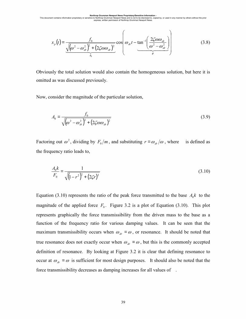
Northrop Grumman Newport News Proprietary/Sensitive Information - This document contains information proprietary or sensitive to Northrop Grumman Newport News and is not to be disclosed to, copied by, or used in any manner by others without the prior
express, written permission of Northrop Grumman Newport News.
39
( )( ) ( )
−
−+−
= −
44 344 214444 34444 21 φ
ωωζωωω
ζωωωω22
1
2222
0 2tancos2
0
dr
drdr
A
drdr
p tftx (3.8)
Obviously the total solution would also contain the homogeneous solution, but here it is
omitted as was discussed previously.
Now, consider the magnitude of the particular solution,
( ) ( )2222
00
2 drdr
fAζωωωω +−
= (3.9)
Factoring out 2ω , dividing by mF0 , and substituting ωωdrr = , where is defined as
the frequency ratio leads to,
( ) ( )2220
0
21
1
rrFkA
ζ+−= (3.10)
Equation (3.10) represents the ratio of the peak force transmitted to the base kA0 to the
magnitude of the applied force 0F . Figure 3.2 is a plot of Equation (3.10). This plot
represents graphically the force transmissibility from the driven mass to the base as a
function of the frequency ratio for various damping values. It can be seen that the
maximum transmissibility occurs when ωω =dr , or resonance. It should be noted that
true resonance does not exactly occur when ωω =dr , but this is the commonly accepted
definition of resonance. By looking at Figure 3.2 it is clear that defining resonance to
occur at ωω =dr is sufficient for most design purposes. It should also be noted that the
force transmissibility decreases as damping increases for all values of .

Northrop Grumman Newport News Proprietary/Sensitive Information - This document contains information proprietary or sensitive to Northrop Grumman Newport News and is not to be disclosed to, copied by, or used in any manner by others without the prior
express, written permission of Northrop Grumman Newport News.
40
Figure 3.2: Force Transmissibility (Direct Excitation)
3.1.2 The Base Excitation Problem
Applying Newton’s Second Law to the system shown in Figure 3.1a leads to the
equations of motion for the system,
( ) ( ) 0=−+−+ gg xxkxxcxm &&&& (3.11)
Substituting the assumed form for the base excitation ( ) ( )tXtx bgg ωsin= into Equation
(3.11) yields,
( ) ( )tkXtcXkxxcxm bgbbg ωωω sincos +=++ &&& (3.12)
FORCE TRANSMISSIBILITY(Base Excitation)
0.0001
0.001
0.01
0.1
1
10
100
0 1 2 3
Frequency Ratio (ωωωωb/ωωωω)
T.R
.
ζ = 0.01
ζ = 0.05
ζ = 0.10
ζ = 0.20
ζ = 0.50
ζ = 1.00
ζ Increasing

Northrop Grumman Newport News Proprietary/Sensitive Information - This document contains information proprietary or sensitive to Northrop Grumman Newport News and is not to be disclosed to, copied by, or used in any manner by others without the prior
express, written permission of Northrop Grumman Newport News.
41
Dividing Equation (3.12) by m and using the definitions of damping ratio and natural
frequency defined in Section 3.1.1 leads to,
( ) ( )tYtYxxx bbb ωωωζωωωζω sincos22 22 +=++ &&& (3.13)
As explained in Section 3.1.1 the particular solution to Equation (3.13) is desired. The
particular solution to Equation (3.13) consists of two parts, one for each harmonic input.
The particular solution for the first harmonic input ( )tY bb ωζωω cos2 follows from the
method of undetermined coefficients as detailed in Section 3.1.1. The solution can be
determined directly by substituting Ybζωω2 for 0f in Equation (3.8). The result is,
( )
( ) ( )
−
−+−
= −22
1
2222
1 2tancos2
2
b
bb
bb
bp tYx
ωωζωωω
ζωωωω
ζωω (3.14)
The particular solution for the second harmonic input ( )tY bωω sin2 can be determined by
following the method of undetermined coefficients as detailed in Section 3.1.1. The
result is,
( )
( ) ( )
−
−+−
= −22
1
22
222
22 2tansin
2 b
bb
b
p tYxωω
ζωωωζωωωω
ω (3.15)
By the principle of superposition the total particular solution is the sum of the two
particular solutions given by Equations (3.14) and (3.15). Therefore, the total particular
solution is,
( ) ( ) ( )
( )( ) ( )
−
−
−
+−
+=
+=
−−
bb
bb
bb
ppp
tY
xxtx
ζωω
ωωζωωω
ζωωωωζωωω
2tan2tancos
22 1
221
21
2222
22
21
(3.16)

Northrop Grumman Newport News Proprietary/Sensitive Information - This document contains information proprietary or sensitive to Northrop Grumman Newport News and is not to be disclosed to, copied by, or used in any manner by others without the prior
express, written permission of Northrop Grumman Newport News.
42
Defining the magnitude of the particular solution ( )txp by X and utilizing the definition
of the frequency ratio ωωbr = yields,
( )( ) ( )
21
222
2
2121
+−
+=rr
YXζ
ζω (3.17)
Dividing Equation (3.17) by Y gives,
( )( ) ( )
21
222
2
2121
+−
+=rrY
Xζ
ζω (3.18)
Equation (3.18) represents the ratio of the maximum response magnitude to the input
displacement magnitude, or the displacement transmissibility. Equation (3.18) is plotted
in Figure 3.3. From the figure it can be seen that for frequency ratios less than 2 the
motion of the isolated mass is greater in amplitude that the motion of the base. However,
for frequency ratios greater than 2 the amplitude of the motion of the isolated mass is
less than that of the base. Therefore, if isolation in terms of diminished motion of the
isolated mass is the design goal, then it is desirable for the isolation system to have a
natural frequency ω that results in a frequency ratio greater than 2 . It should also be
noted that the effectiveness of the isolation system in terms of displacement
transmissibility is diminished as the damping ratio increases. Therefore, if minimizing
displacement transmissibility is the design goal then the isolation system should be
lightly damped.
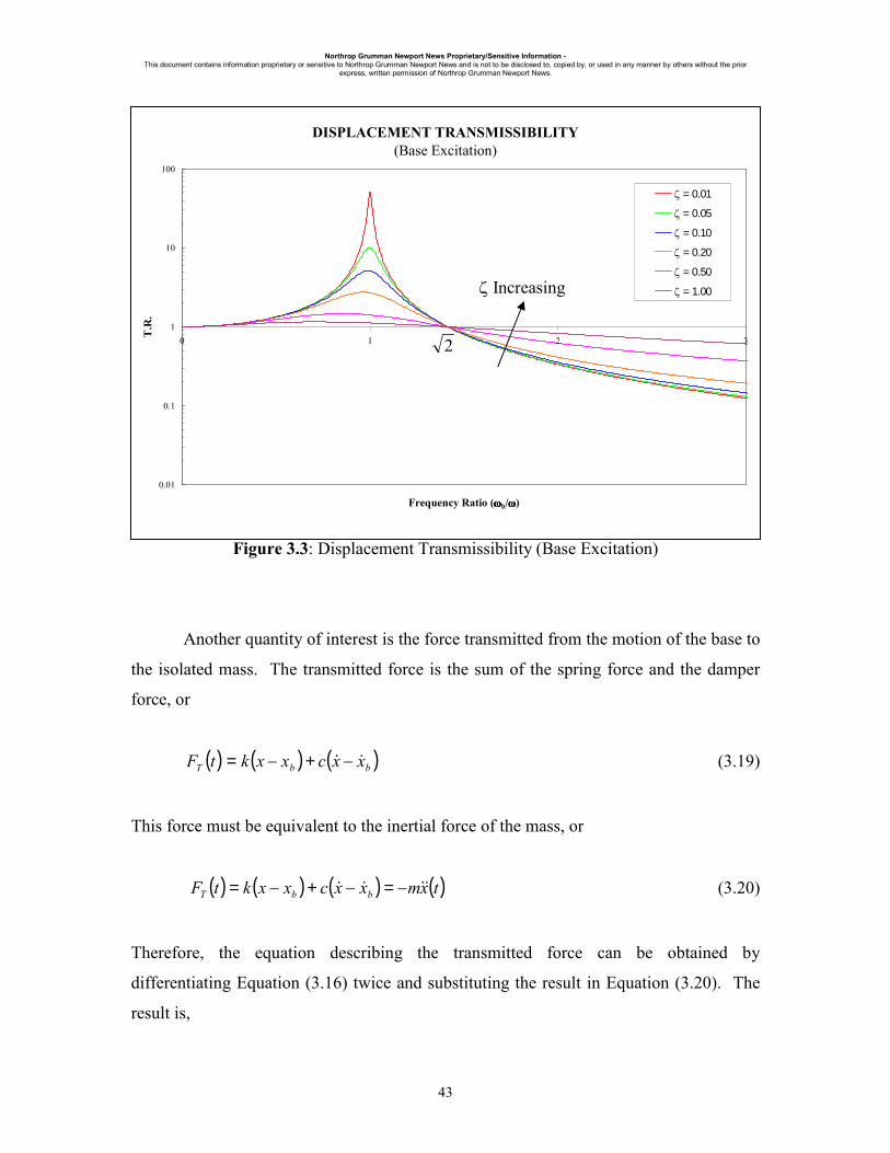
Northrop Grumman Newport News Proprietary/Sensitive Information - This document contains information proprietary or sensitive to Northrop Grumman Newport News and is not to be disclosed to, copied by, or used in any manner by others without the prior
express, written permission of Northrop Grumman Newport News.
Figure 3.3: Displacement Transmissibility (Base Excitation)
Another quantity of interest is the force transmitted from the motion of the base to
the isolated mass. The transmitted force is the sum of the spring force and the damper
force, or
( ) ( ) ( )bbT xxcxxktF && −+−= (3.19)
This force must be equivalent to the inerti
( ) ( ) ( ) mxxcxxktF bbT && −=−+−=
Therefore, the equation describing t
differentiating Equation (3.16) twice and
result is,
2
DISPLACEMENT TRANSMISSIBILITY(Base Excitation)
0.01
0.1
1
10
100
0 1 2 3
Frequency Ratio (ωωωωb/ωωωω)
T.R
.
ζ = 0.01
ζ = 0.05
ζ = 0.10
ζ = 0.20
ζ = 0.50
ζ = 1.00ζ Increasing
43
al force of the mass, or
( )tx&& (3.20)
he transmitted force can be obtained by
substituting the result in Equation (3.20). The

Northrop Grumman Newport News Proprietary/Sensitive Information - This document contains information proprietary or sensitive to Northrop Grumman Newport News and is not to be disclosed to, copied by, or used in any manner by others without the prior
express, written permission of Northrop Grumman Newport News.
44
( ) ( )( ) ( )
−
−
−
+−
+= −−
bb
bb
bb
bbT tYmtF
ζωω
ωωζωωω
ζωωωωζωωωω
2tan2tancos
22 1
221
21
2222
222
(3.21)
Therefore, the magnitude of the transmitted force is,
( )( ) ( )
21
2222
222
22
+−
+=bb
bbT YmF
ζωωωωζωωωω (3.22)
Substituting the definition for the frequency ratio ωωbr = into Equation (3.22) gives,
( )( ) ( )
21
222
22
2121
+−
+=rr
rkYrFTζ
ζ (3.23)
Dividing Equation (3.23) by kY results in the force transmissibility ratio,
( )( ) ( )
21
222
22
2121
+−
+=rr
rrkYFT
ζζ (3.24)
This equation represents the ratio of the magnitude of the force transmitted to the isolated
mass to the magnitude of the force applied to the isolation system due to the motion of
the base. Figure 3.4 is a plot of Equation (3.24). Note that unlike the displacement
transmissibility, the force transmissibility does not necessarily decrease for all 2>r .
In fact as damping increases the transmitted force can increase significantly for 2>r .
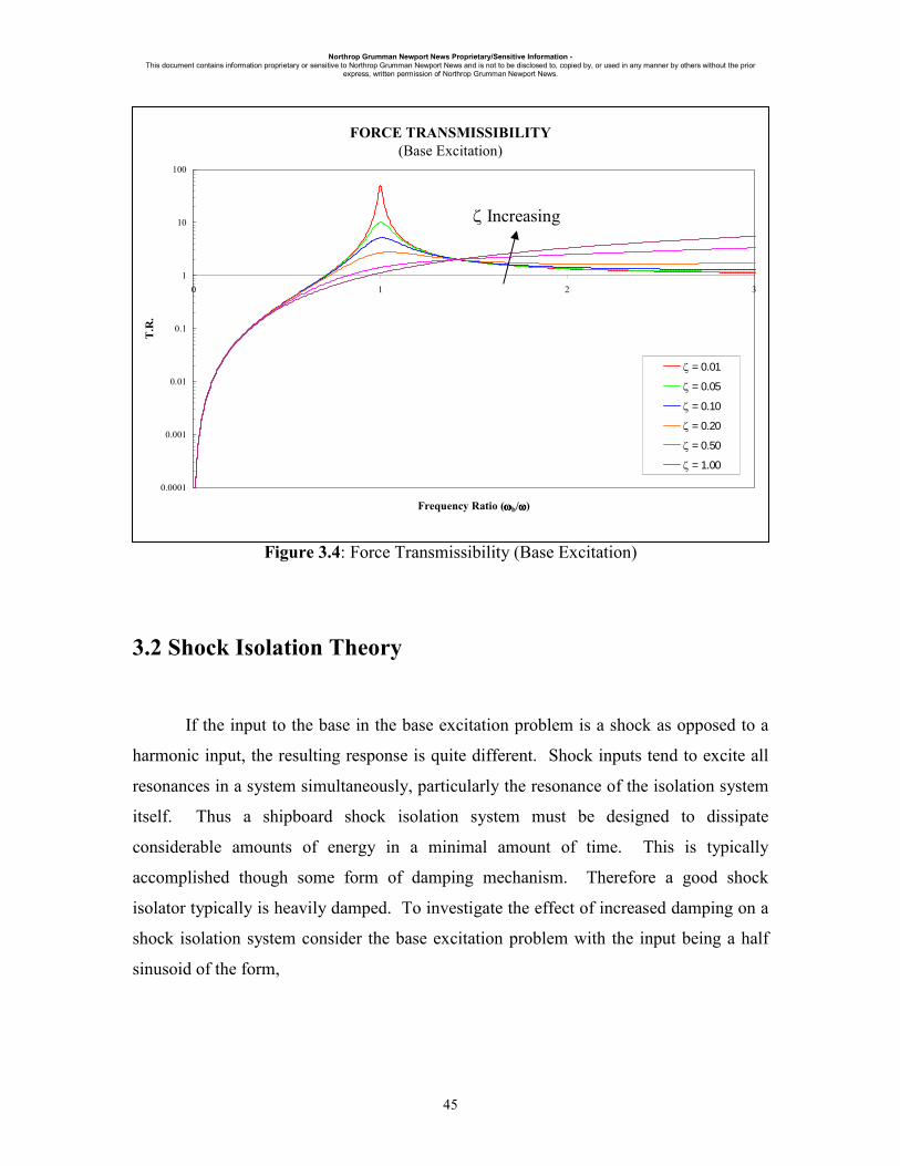
Northrop Grumman Newport News Proprietary/Sensitive Information - This document contains information proprietary or sensitive to Northrop Grumman Newport News and is not to be disclosed to, copied by, or used in any manner by others without the prior
express, written permission of Northrop Grumman Newport News.
45
Figure 3.4: Force Transmissibility (Base Excitation)
3.2 Shock Isolation Theory
If the input to the base in the base excitation problem is a shock as opposed to a
harmonic input, the resulting response is quite different. Shock inputs tend to excite all
resonances in a system simultaneously, particularly the resonance of the isolation system
itself. Thus a shipboard shock isolation system must be designed to dissipate
considerable amounts of energy in a minimal amount of time. This is typically
accomplished though some form of damping mechanism. Therefore a good shock
isolator typically is heavily damped. To investigate the effect of increased damping on a
shock isolation system consider the base excitation problem with the input being a half
sinusoid of the form,
FORCE TRANSMISSIBILITY(Base Excitation)
0.0001
0.001
0.01
0.1
1
10
100
0 1 2 3
Frequency Ratio (ωωωωb/ωωωω)
T.R
.
ζ = 0.01
ζ = 0.05
ζ = 0.10
ζ = 0.20
ζ = 0.50
ζ = 1.00
ζ Increasing

Northrop Grumman Newport News Proprietary/Sensitive Information - This document contains information proprietary or sensitive to Northrop Grumman Newport News and is not to be disclosed to, copied by, or used in any manner by others without the prior
express, written permission of Northrop Grumman Newport News.
46
( )
=>
=≤≤=
p
pp
gtt
tttYtx
ωπωπω
1
1
0
0sin (3.25)
Figure 3.5 is as plot of the response of a 2.27 Hz isolator to the base excitation described
in Equation (3.25).
Figure 3.5: Acceleration Transmissibility (Base Excitation)
From Figure 3.5 it can be seen that in terms of shock isolation performance it is desirable
for the isolation system to be heavily damped.
ACCELERATION TRANSMISSIBILITY(Base Excitation)
0
0.2
0.4
0.6
0.8
1
1.2
1.4
1.6
1.8
2
0 5 10 15 20
Frequency Ratio (ωωωω/ωωωωP)
T.R
.
ζ = 0.00ζ = 0.05ζ = 0.10ζ = 0.20ζ = 0.30ζ = 0.50ζ = 0.80ζ = 1.00
ζ Increasing

Northrop Grumman Newport News Proprietary/Sensitive Information - This document contains information proprietary or sensitive to Northrop Grumman Newport News and is not to be disclosed to, copied by, or used in any manner by others without the prior
express, written permission of Northrop Grumman Newport News.
47
3.3 Combined Shock and Vibration Isolation
A common misconception is that a good shock isolation system must be
mechanically “stiff”. In reality “soft” isolation systems, such as air springs perform very
well as shock isolators. A soft system tends to behave as a mechanical low pass filter and
any high frequency input, such as typical ship-shock input, tend to be mitigated when
passing through a low frequency device. Very little of this high frequency energy passes
through to the isolated mass. However, the problem with a low frequency device is that
shock inputs tend to excite the resonance of the isolator. Being a low frequency device
this tends to result in significant deflections that are often unacceptable due to rattle space
requirements.
By looking at Figures 3.3 and 3.4 it can be seen that increasing damping is
detrimental to both the force and displacement transmissibility under vibration inputs.
However, as was shown in Figure 3.5 large amounts of damping are required in a shock
isolation system. This is the classic trade-off in shock and vibration isolation system
design. A good compromise is to use a controllable damper that provides light damping
in vibration isolation mode, but can be turned on during a shock event to provide the
large amounts of damping necessary for controlling the effect of the shock input.

Northrop Grumman Newport News Proprietary/Sensitive Information - This document contains information proprietary or sensitive to Northrop Grumman Newport News and is not to be disclosed to, copied by, or used in any manner by others without the prior
express, written permission of Northrop Grumman Newport News.
48
Chapter 4
Ship Shock Analysis and Testing
4.1 Ship Shock Inputs
A ship can be subjected to many different types of shock inputs such as wave
slap, impact, weapons air blast, etc. In this dissertation it is assumed that the shock input
to the ship is due to a near-miss underwater weapons explosion. Typically this is the
most damaging input to a ship and is the input most often considered in ship design. A
weapon exploding underwater produces a gas bubble that initially expands rapidly and
simultaneously an initial transient pressure wave propagates outward. As the bubble is
forming it is simultaneously being carried toward to water surface by buoyant forces. At
some point the internal pressure in the bubble cannot support the weight of the
surrounding water and the bubble collapses. The implosion of the bubble causes a
second pressure wave to propagate (the so-called “Bubble Pulse”) and the bubble
expands again. This process is repeated until the bubble breaks the surface of the water.
The bubble development is shown graphically in Figure 4.1.
Figure 4.1: UNDEX Bubble Development

Northrop Grumman Newport News Proprietary/Sensitive Information - This document contains information proprietary or sensitive to Northrop Grumman Newport News and is not to be disclosed to, copied by, or used in any manner by others without the prior
express, written permission of Northrop Grumman Newport News.
49
The propagating pressure wave is the destructive force in these near-miss
explosive events. In terms of destructive potential the initial transient is the most
damaging to a ship. However, the pressure wave developed by the first bubble collapse
can be significant in terms of damage potential as well.
The pressure waves produced by the underwater explosion then propagate through
the water and eventually impinge upon the ship’s hull. This pressure wave then excites
the ship’s structure. Equipment that is mounted near the hull experiences a shock that is
similar to the hull motion. A typical hull-level motion due to an underwater explosion is
shown in Figure 4.2.
Figure 4.2: Typical Hull-Level Response to an UNDEX Event
Note that the input tends to contain fairly high frequencies and that the majority of
the energy is contained in the early time. As the energy travels through the ship’s
structure it is dissipated through structural damping and other means. In addition its
character is modified by the excited structure. For example, a deck excited by the
UNDEX RESPONSE TO FSP TEST(INNER BOTTOM)
-150
-100
-50
0
50
100
150
200
250
0 0.5 1 1.5
Time (s)
Vel
ocity
(in/s
)
-20
-15
-10
-5
0
5
10
15
Dis
plac
emen
t(in
)
VelocityDisplacement

Northrop Grumman Newport News Proprietary/Sensitive Information - This document contains information proprietary or sensitive to Northrop Grumman Newport News and is not to be disclosed to, copied by, or used in any manner by others without the prior
express, written permission of Northrop Grumman Newport News.
50
propagating shock wave will oscillate at its fundamental frequency. Figure 4.3 is a plot
of a typical deck-level motion.
Figure 4.3: Typical Deck-Level Response to an UNDEX Event
Note that the amplitude of the motion has been reduced due to the dissipation of
the energy as the wave propagates through the ships structure. Also note the predominant
frequency content at the deck-level occurs at the fundamental frequency of the deck, in
this case 14 Hz.
4.2 Navy Shock Test Machines
Due to the danger and difficulty of shock testing a ship with underwater
explosives, several machines have been developed over the years to simulate an input due
UNDEX RESPONSE TO FSP TEST(WITH 14 Hz DECK FIXTURE)
-150
-100
-50
0
50
100
150
200
0 0.5 1 1.5 2
Time (s)
Vel
ocity
(in/s)
-15
-10
-5
0
5
10
15
20
Dis
plac
emen
t(in
)
VelocityDisplacement

Northrop Grumman Newport News Proprietary/Sensitive Information - This document contains information proprietary or sensitive to Northrop Grumman Newport News and is not to be disclosed to, copied by, or used in any manner by others without the prior
express, written permission of Northrop Grumman Newport News.
51
to an UNDEX event. Figures 4.4 through 4.6 depict the currently accepted Navy shock
test machines.
Figure 4.4: Lightweight Shock Machine
Figure 4.5: Medium Weight Shock Test Machine

Northrop Grumman Newport News Proprietary/Sensitive Information - This document contains information proprietary or sensitive to Northrop Grumman Newport News and is not to be disclosed to, copied by, or used in any manner by others without the prior
express, written permission of Northrop Grumman Newport News.
52
Figure 4.6: Floating Shock Platform
The decision to use one machine or the other is based on the weight of the
equipment to be tested. The Lightweight Shock Machine, shown in Figure 4.4 is used for
test articles up to 350 lbs. The Medium Weight Shock Machine, shown in Figure 4.5, is
used for test articles up to 7,400 lbs. The Floating Shock Platform, shown in Figure 4.6,
is used for test articles of up to 60,000 lbs. The Lightweight and Medium Weight Shock
Machine are impact machines and the excitation to the test article is provided by a
hammer impacting an anvil. With the Floating Shock Platform the excitation is provided
by a high explosive charge placed underwater at various stand-off distances from the
FSP. Figure 4.7 shows an FSP undergoing a test. Note that a typical test only involves
one charge and that Figure 4.7 represents a rare double shot.
Figure 4.7: FSP During an UNDEX Test (Double Shot)

Northrop Grumman Newport News Proprietary/Sensitive Information - This document contains information proprietary or sensitive to Northrop Grumman Newport News and is not to be disclosed to, copied by, or used in any manner by others without the prior
express, written permission of Northrop Grumman Newport News.
53
The FSP is essentially a floating barge to which test articles can be attached. The
FSP arguably provides a more accurate representation of what happens on an actual ship
during an UNDEX event. To simulate a hull-mounted condition test articles can be
mounted directly to inner bottom of the hull. To simulate a deck mounted condition
Deck Simulator Fixtures (DSF) can be installed in the FSP to simulate deck of various
frequencies.