combined edge trim installation - acs stainless steel … · combined edge trim installation ......
TRANSCRIPT
ACS Stainless Steel Fixings Ltd, 1 Cross Green Approach, Cross Green Industrial Park, Leeds, LS9 0SG
Tel: 0113 391 8200 Fax: 0113391 8209
Web: www.acsstainless.co.uk Page 1 of 3 ACS Installation
Training & Seminars
Combined Edge Trim Installation Introduction CET has been developed for use with steel frame structures and acts as a
permanent shuttering when pouring concrete in-situ onto ribbed decking
floors. One of the main advantages of this system is that the profiled edge
trim incorporates a channel for casting into the concrete to enable the fixing
of masonry support angles, windposts & curtain walling at a later stage, as it
is often not practical to site drill and fix into the concrete slab, as the
thicknesses of the slabs are usually limited
ACS CET is supplied in standard 3 metre lengths which are positioned
around the perimeter of the building butted together and taped to prevent the
egress of concrete during pouring. The standard lengths can be easily cut to
suit the length of a run or alternatively special corner details and other
special fabricated sections can be manufactured as required. The edge trim
is fixed to top of the steel beam and then restrained using straps fixed to the
metal deck to ensure the line of the vertical face remains plumb during the
pouring process.
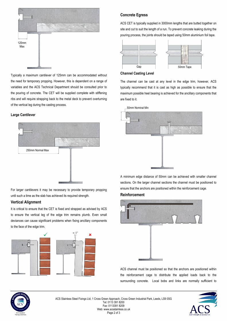
Safety Although every effort is made to remove sharp
edges during the manufacture of the product,
appropriate personal protective equipment
should always be worn when handling and
installing masonry support to avoid injury.
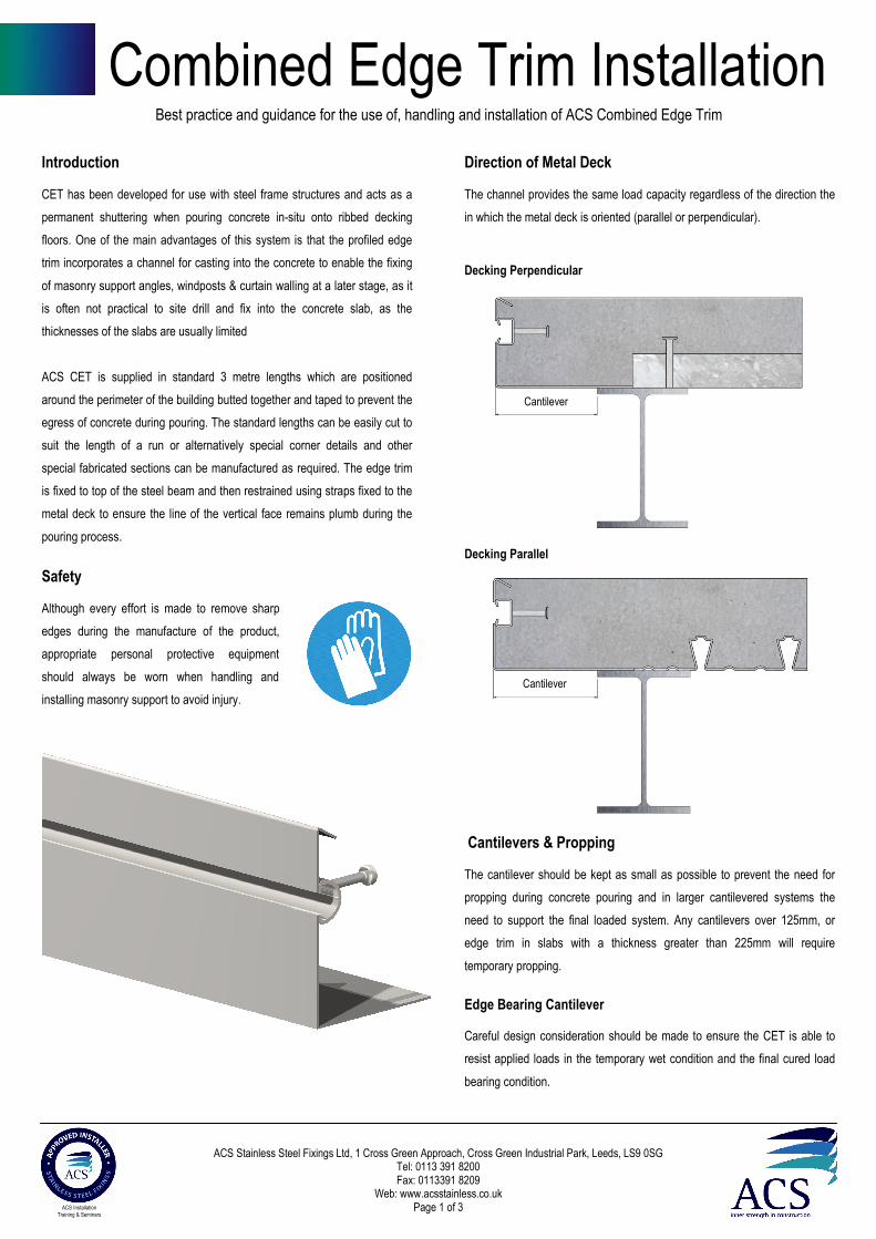
Direction of Metal Deck The channel provides the same load capacity regardless of the direction the
in which the metal deck is oriented (parallel or perpendicular).
Decking Perpendicular
Decking Parallel
Cantilevers & Propping The cantilever should be kept as small as possible to prevent the need for
propping during concrete pouring and in larger cantilevered systems the
need to support the final loaded system. Any cantilevers over 125mm, or
edge trim in slabs with a thickness greater than 225mm will require
temporary propping.
Edge Bearing Cantilever Careful design consideration should be made to ensure the CET is able to
resist applied loads in the temporary wet condition and the final cured load
bearing condition.
Best practice and guidance for the use of, handling and installation of ACS Combined Edge Trim
Cantilever
Cantilever
ACS Stainless Steel Fixings Ltd, 1 Cross Green Approach, Cross Green Industrial Park, Leeds, LS9 0SG
Tel: 0113 391 8200 Fax: 0113391 8209
Web: www.acsstainless.co.uk Page 2 of 3 ACS Installation
Training & Seminars
Typically a maximum cantilever of 125mm can be accommodated without
the need for temporary propping. However, this is dependent on a range of
variables and the ACS Technical Department should be consulted prior to
the pouring of concrete. The CET will be supplied complete with stiffening
ribs and will require strapping back to the metal deck to prevent overturning
of the vertical leg during the casting process.
Large Cantilever
For larger cantilevers it may be necessary to provide temporary propping
until such a time as the slab has achieved its required strength.
Vertical Alignment
It is critical to ensure that the CET is fixed and strapped as advised by ACS
to ensure the vertical leg of the edge trim remains plumb. Even small
deviances can cause significant problems when fixing ancillary components
to the face of the edge trim.
Concrete Egress ACS CET is typically supplied in 3000mm lengths that are butted together on
site and cut to suit the length of a run. To prevent concrete leaking during the
pouring process, the joints should be taped using 50mm aluminium foil tape.
Channel Casting Level The channel can be cast at any level in the edge trim, however, ACS
typically recommend that it is cast as high as possible to ensure that the
maximum possible heel bearing is achieved for the ancillary components that
are fixed to it.
A minimum edge distance of 50mm can be achieved with smaller channel
sections. On the larger channel sections the channel must be positioned to
ensure that the anchors are positioned within the reinforcement cage.
Reinforcement
ACS channel must be positioned so that the anchors are positioned within
the reinforcement cage to distribute the applied loads back to the
surrounding concrete. Local bobs and links are normally sufficient to
125mm
Max
250mm Normal Max
� �
Gap 50mm Tape
< 1°
50mm Nominal Min
ACS Stainless Steel Fixings Ltd, 1 Cross Green Approach, Cross Green Industrial Park, Leeds, LS9 0SG
Tel: 0113 391 8200 Fax: 0113391 8209
Web: www.acsstainless.co.uk Page 3 of 3 ACS Installation
Training & Seminars
achieve this, but mesh reinforcement can also be used.
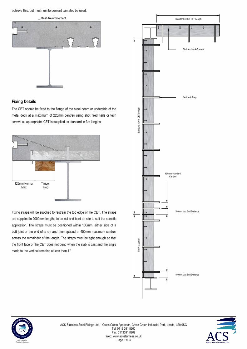
Fixing Details
The CET should be fixed to the flange of the steel beam or underside of the
metal deck at a maximum of 225mm centres using shot fired nails or tech
screws as appropriate. CET is supplied as standard in 3m lengths
Fixing straps will be supplied to restrain the top edge of the CET. The straps
are supplied in 2000mm lengths to be cut and bent on site to suit the specific
application. The straps must be positioned within 100mm, either side of a
butt joint or the end of a run and then spaced at 450mm maximum centres
across the remainder of the length. The straps must be tight enough so that
the front face of the CET does not bend when the slab is cast and the angle
made to the vertical remains at less than 1°.
Mesh Reinforcement
125mm Normal Max
Timber Prop
450mm Standard Centres
100mm Max End Distance
100mm Max End Distance
Restraint Strap
Stud Anchor & Channel
Standard 3.00m CET Length
Sta
ndar
d 3.
00m
CE
T L
engt
h S
ite C
ut L
engt
h