combinational circuits 06-02-2016 - university of maryland · combinational vs sequential circuits...
TRANSCRIPT

Combinational Circuits
Jason Filippou
CMSC250 @ UMCP
06-02-2016
Jason Filippou (CMSC250 @ UMCP) Circuits 06-02-2016 1 / 1

Outline
Jason Filippou (CMSC250 @ UMCP) Circuits 06-02-2016 2 / 1

Hardware design levels
Hardware design levels
Jason Filippou (CMSC250 @ UMCP) Circuits 06-02-2016 3 / 1
Hardware design levels
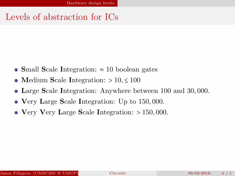
Levels of abstraction for ICs
Small Scale Integration: ≈ 10 boolean gates
Medium Scale Integration: > 10,≤ 100
Large Scale Integration: Anywhere between 100 and 30,000.
Very Large Scale Integration: Up to 150,000.
Very Very Large Scale Integration: > 150,000.
Jason Filippou (CMSC250 @ UMCP) Circuits 06-02-2016 4 / 1
Hardware design levels
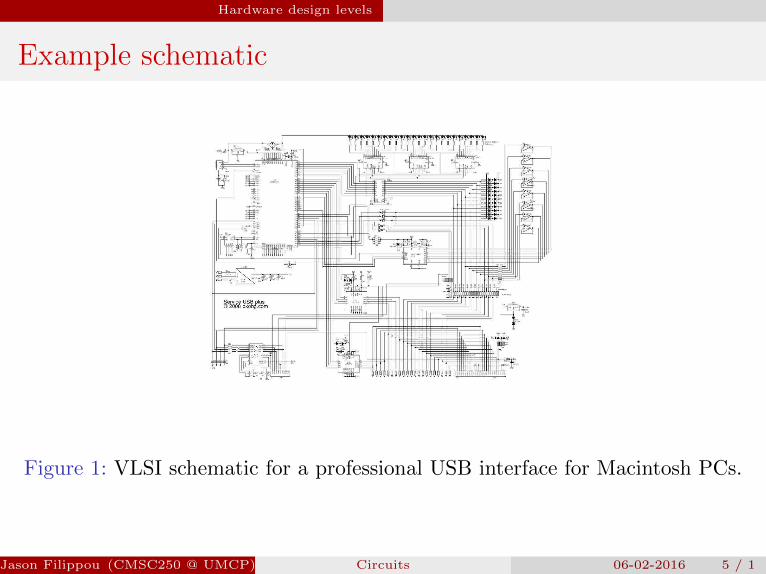
Example schematic
Figure 1: VLSI schematic for a professional USB interface for Macintosh PCs.
Jason Filippou (CMSC250 @ UMCP) Circuits 06-02-2016 5 / 1

Hardware design levels
SSI
Consists of circuits that contain about 10 gates.
16-bit adders.Encoders / Decoders.MUX/DEMUX.. . .
All our examples will be at an SSI level.
Logic Design is the branch of Computer Science that essentiallyanalyzes the kinds of circuits and optimizations done at anSSI/MSI level.
We do not have such a course in the curriculum, but you can expectto be exposed to it if you ever take 411.
Jason Filippou (CMSC250 @ UMCP) Circuits 06-02-2016 6 / 1

Combinational Circuit Design
Combinational Circuit Design
Jason Filippou (CMSC250 @ UMCP) Circuits 06-02-2016 7 / 1

Combinational Circuit Design
Combinational vs Sequential circuits
A combinational circuit is one where the output of a gate isnever used as an input into it.
A sequential circuit is one where this constraint can be violated.
Example: Flip-flops (yes, seriously).
In this course, we will only touch upon combinational circuits.
Jason Filippou (CMSC250 @ UMCP) Circuits 06-02-2016 8 / 1
Combinational Circuit Design Boolean Gates
Boolean Gates
Jason Filippou (CMSC250 @ UMCP) Circuits 06-02-2016 9 / 1

Combinational Circuit Design Boolean Gates
Analogy between logic and hardware
Every binary or unary boolean operator (∧,∨, ∼) is mapped to agate.
This includes the binary connectives (⇒,⇔) (why?)
So, every propositional logic construct (“compound” orotherwise) can be mapped to a logically equivalent booleancircuit!
Jason Filippou (CMSC250 @ UMCP) Circuits 06-02-2016 10 / 1
Combinational Circuit Design Boolean Gates
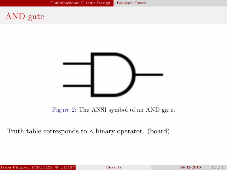
AND gate
Figure 2: The ANSI symbol of an AND gate.
Truth table corresponds to ∧ binary operator. (board)
Jason Filippou (CMSC250 @ UMCP) Circuits 06-02-2016 11 / 1
Combinational Circuit Design Boolean Gates
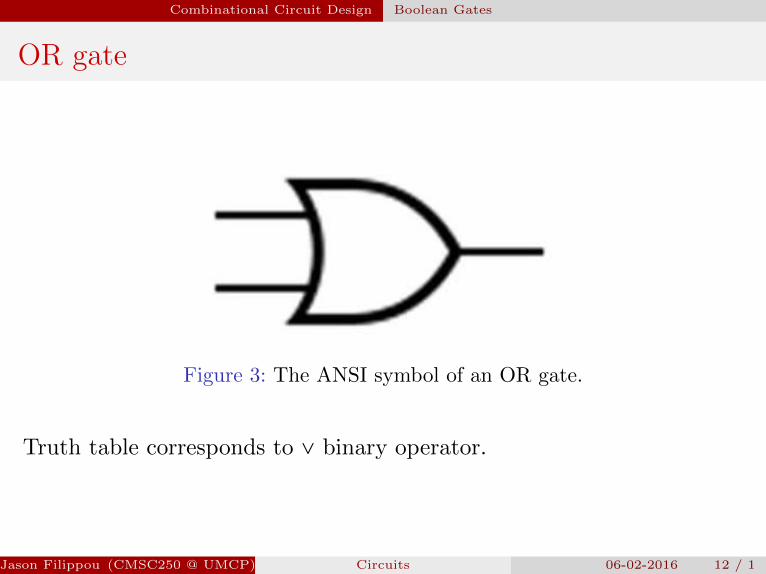
OR gate
Figure 3: The ANSI symbol of an OR gate.
Truth table corresponds to ∨ binary operator.
Jason Filippou (CMSC250 @ UMCP) Circuits 06-02-2016 12 / 1
Combinational Circuit Design Boolean Gates
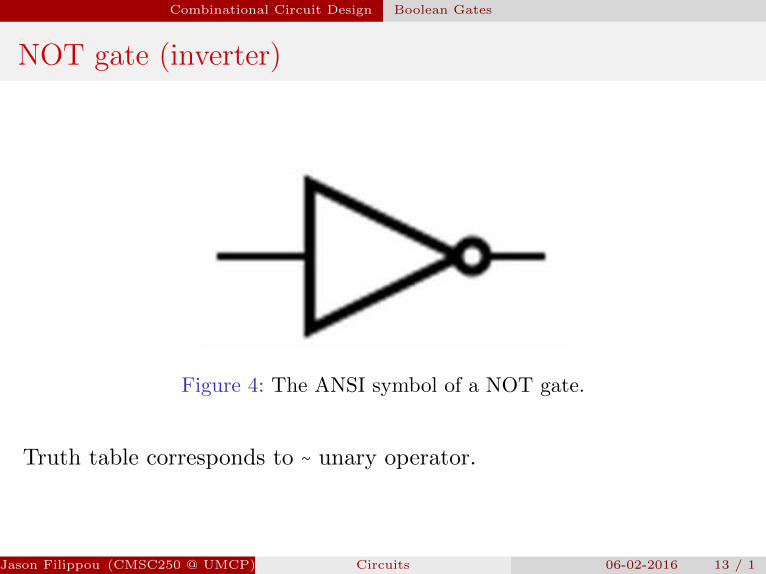
NOT gate (inverter)
Figure 4: The ANSI symbol of a NOT gate.
Truth table corresponds to ∼ unary operator.
Jason Filippou (CMSC250 @ UMCP) Circuits 06-02-2016 13 / 1
Combinational Circuit Design Boolean Gates
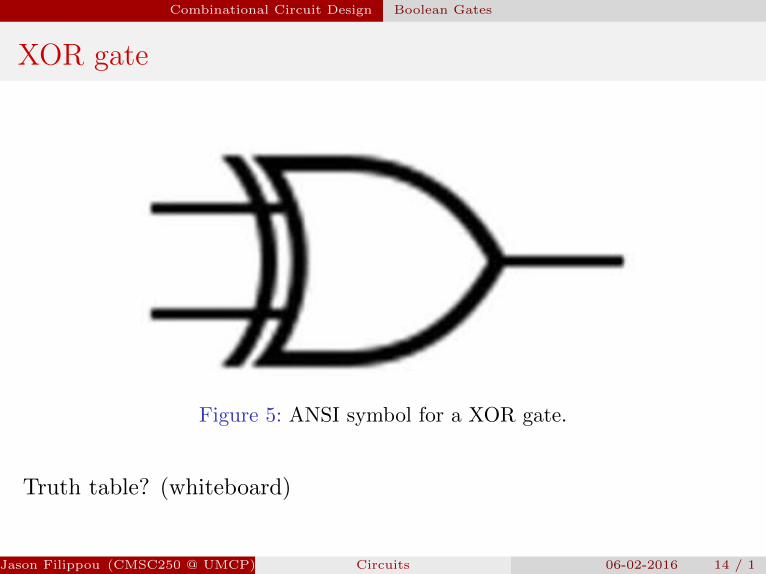
XOR gate
Figure 5: ANSI symbol for a XOR gate.
Truth table? (whiteboard)
Jason Filippou (CMSC250 @ UMCP) Circuits 06-02-2016 14 / 1
Combinational Circuit Design Boolean Gates
XOR gate
Can I implement a XOR gate using gates I know?
Homework ,
Jason Filippou (CMSC250 @ UMCP) Circuits 06-02-2016 15 / 1

Combinational Circuit Design Boolean Gates
XOR gate
Can I implement a XOR gate using gates I know?
Homework ,
Jason Filippou (CMSC250 @ UMCP) Circuits 06-02-2016 15 / 1

Combinational Circuit Design Boolean Gates
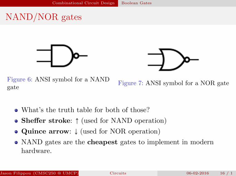
NAND/NOR gates
Figure 6: ANSI symbol for a NANDgate
Figure 7: ANSI symbol for a NOR gate
What’s the truth table for both of those?
Sheffer stroke: ↑ (used for NAND operation)
Quince arrow: ↓ (used for NOR operation)
NAND gates are the cheapest gates to implement in modernhardware.
Jason Filippou (CMSC250 @ UMCP) Circuits 06-02-2016 16 / 1

Combinational Circuit Design Boolean Gates
NAND/NOR gates
Figure 6: ANSI symbol for a NANDgate
Figure 7: ANSI symbol for a NOR gate
What’s the truth table for both of those?
Sheffer stroke: ↑ (used for NAND operation)
Quince arrow: ↓ (used for NOR operation)
NAND gates are the cheapest gates to implement in modernhardware.
Jason Filippou (CMSC250 @ UMCP) Circuits 06-02-2016 16 / 1
Combinational Circuit Design Complex circuits
Complex circuits
Jason Filippou (CMSC250 @ UMCP) Circuits 06-02-2016 17 / 1
Combinational Circuit Design Complex circuits
Examples
Convert the following boolean expressions to their correspondingcircuits:
(p ∧ q ∧ z) ∨ (∼r)(p ∨ q) ∧ q
Now, convert them into circuits that only use NAND gates!
Jason Filippou (CMSC250 @ UMCP) Circuits 06-02-2016 18 / 1

Combinational Circuit Design Complex circuits
Simplifying circuits
We can often use the axioms of boolean logic to simplify a circuitinto one that uses a smaller number of gates.
Then, we can convert that circuit into one that only uses NANDgates!
Pipeline (Important to remember!):1 Identify boolean expression implemented by the circuit (tip: scan
the circuit from output to inputs).2 Use axioms of boolean algebra to simplify expression in terms of
boolean connectives used.3 Use axioms of boolean algebra to translate the expression into one
that only uses (possibly negated) conjunctions (∼(p ∧ ∼q ∧ z ∧ . . . ).4 Draw the corresponding circuit.
Jason Filippou (CMSC250 @ UMCP) Circuits 06-02-2016 19 / 1

Combinational Circuit Design Complex circuits
Examples
Whiteboard...
Jason Filippou (CMSC250 @ UMCP) Circuits 06-02-2016 20 / 1
Combinational Circuit Design Complex circuits
K-maps
A much more efficient way to quickly simplify circuits is theKarnaugh map, or K-map for short.1
Automatically converts any boolean expression to either asum-of-product form (ORs of ANDs) or product-of-sums form(ANDs of ORs).
We will not analyze them in this course, but you’re directed to theWikipedia article for information.
1Named such after Maurice Karnaugh.Jason Filippou (CMSC250 @ UMCP) Circuits 06-02-2016 21 / 1