combi sensor module - led shop -der led … · rc5/rc6, nec, sony, nokia . ... be manually...
TRANSCRIPT

© 2015, Lunatone Industrielle Elektronik GmbH DALI CS
DALI CS
Datasheet
Combi Sensor Module
Sensor unit for automatic lighting
control in DALI systems
Art. Nr. 86458621 (DALI CS Temp)
Art.Nr. 86458672 (DALI CS IR)

DALI CS, Datasheet © 2015, Lunatone Industrielle Elektronik GmbH
DALI CS Combi Sensor Module
Overview
• Sensor Module for DALI lighting
systems
• Motion detection
• Light intensity measurement
• motion dependent control
• Sensor for ambient temperature
measurement and monitoring (type
DALI CS Temp)
• integrated IR remote control receiver
(DALI CS IR)
• The DALI CS module can be used
either as active lighting control unit or
just for measurements and monitoring
• Sensor properties are set easily via the
“DALI-Cockpit” software tool
• The DALI CS is able to transmit DALI-
commands (e.g. ON, OFF, RECALL
MIN/MAX, GO TO SCENE X, …) to
single destination addresses, group
addresses or broadcast.
• The rotary switch on the back of the
housing helps to assign a destination
group address easily
• Several DALI CS modules can be used
within one DALI-line
• The compact module can easily be
installed in recessed conduit boxes or
directly on cavity walls.
• The DALI CS must not be connected to
the mains. It is directly supplied by the
DALI-line.
Specification, Characteristics
Type DALI CS Temp DALI CS IR
article number 86458621 86458672
power supply aus DALI- Bus
typ. current consumption 3.5 mA (Temp) 4.1mA (IR)
input/ouput DALI
sensors
motion
light intensity
temperature
motion
light intensity
IR receiver
function adjustable
operating temperature 0°C-70°C
storage temperature -25°C-85°C
protection class IP20
connecting wire cross
section 0.5-1.5 mm
2
operating temperature RAL9010
PIR Motion Detection:
distance: <12m, 92 zones
range: hor.: ±51°, vert. ±46°
temp.diff. target to ambience:
>4°C
Light Intensity Measurement:
range: 0-2500lux, resolution: 1lux
Temperature Measurement:
range: 0°C-70°C, resolution: 1°C
IR receiver:
Apple-Remote (7 buttons) or
4 programmable buttons
(universal receiver),
supported protocols: Philips
RC5/RC6, NEC, Sony, Nokia

DALI CS, Datasheet © 2015, Lunatone Industrielle Elektronik GmbH
typical installation
geometry
Installation
The DALI CS module is connected to the DALI-
line. Like all DALI modules it is powered
directly via the DALI signal line, which is
supplied by a DALI PS. A separate power
supply is not needed. A typical value for the
current consumption is 3.5mA.
The DALI-line input is polarity free and
protected against overvoltage of up to
270Vac. DALI signals are not SELV. Therefore
the same procedures should be applied as
working with main voltage. Allowed
connection wire cross sections range from
0.5mm2 to 1.5mm
2.
rear view / mounting ring
The DALI CS mounting ring can be attached to
cavity walls directly or by using an electrical
box. The housing can then simply be attached
on the mounting ring. Even in a flush-mounted
box there is enough room for a sunken sensor
head.

DALI CS, Datasheet © 2015, Lunatone Industrielle Elektronik GmbH
sensor head: sunken and extended
Finally the sensor head can be aligned to the
desired position. Declination angles of 40° in
vertical and 360° in axial direction are
provided.
aligned sensor head
Functionality and Configuration
The DALI CS measures various physical
properties (motion, light intensity and
temperature) and offers the possibility to
react according to the measurements by
sending DALI commands.
Via a DALI-USB interface the software tool
“DALI-Cockpit” can communicate with the
DALI CS. So the desired functionality can be
configured easily on PC. DALI-Cockpit and
DALI-USB interface are required for the
configuration only and can be removed when
configuration is finished. The settings of the
sensor components and the configuration of
the DALI commands and destination addresses
can be defined in the DALI Cockpit. Before
going in detail the functionality of the sensors
and the basic operating conditions of the DALI
CS will be explained.
Motion Detection
The motion sensor is spatially divided into 92
zones. In each zone the received thermal
radiation is determined and differentially
compared to the adjacent zones (PIR sensor).
For motion detection there is a need for a
temperature difference of at least 4°C
between moving object and environment.
Heat sources such as copiers or heaters may
have a negative influence on motion
detection.
This method allows observation of relatively
large areas by using only one sensor head.
With opening angles of 46.3° and 51.3° and a
sensor mounted at a height of 5 meters the 92
zones cover an area of more than 100m2.
The distance between sensor and the object
of interest should be less than 12 meters.
relationship opening angle / detection area

DALI CS, Datasheet © 2015, Lunatone Industrielle Elektronik GmbH
The DALI CS can send DALI commands on
movement detection as well as on
disappearance of a previously detected
motion. In the case of the disappearance of a
previously detected motion a delay time
between the occurrence of the event and the
transmission of the DALI command can be
defined.
timing motion detection / reaction
This functionality offers a simple and
convenient way to implement an automatic
lighting control. The light is turned on and off
as reaction on motion.
Light Intensity Sensor
The light sensor measures illuminance in a
range from 0 to 2500 lux. The resolution is 1
lux. The incident light is rated by the spectral
sensitivity of the human eye and thus a
property for the subjective visual perception
of brightness.
In the DALI-Cockpit switching threshholds for
light intensity can be defined by setting
values for threshold and hysteresis. When the
measured value falls below the lower limit or
exceeds the upper one various DALI-
commands can be selected to be sent as
response.
hysteresis light sensor
Besides direct lighting control the light sensor
can be used for measurement and monitoring
as well. The measured value can be
transmitted to a superimposed control.
A combined functionality of light intensity
sensor and motion detector can be selected
optionally. With this option the motion sensor
can be forced to work only at night while it is
deactivated during daytime.
Temperature Measurement
hysteresis temperature sensor
The temperature sensor covers a range from
0°C to 70°C. The resolution is 1°C. The setting
of switching thresholds is implemented similar
to the light sensor.
The temperature sensor can be used for
measurement and monitoring purposes only.

DALI CS, Datasheet © 2015, Lunatone Industrielle Elektronik GmbH
The measured value can then be transmitted
to a higher level controller.
IR Remote Control Empfänger
The DALI CS is available with infrared (IR)
remote control receiver.
The transmission of DALI commands can then
be manually triggered by a remote control.
The 7 button Apple-Remote is the standard
remote control. Optional learning of up to 4
IR-codes is supported (protocols: Philips RC5,
Philips RC6, NEC, Sony, Nokia, RCAA and X-
Sat).
Configuration
For applications requiring a motion sensor
only the default configuration may be
sufficient. The destination address can be set
by the rotary switch on the rear side of the
sensor (0…Broadcast, 1…15 -> group
addresses G0…G14).
In the default configuration light- and
temperature-sensor are deactivated. The
motion sensor sends the DALI-command
RECALL MAX in case of a detected motion and
the DALI-command OFF (without delay) if
movement isn’t detected any longer. The
destination address is G0...G14 or broadcast
as selected by the rotary switch.
For any other configuration the free DALI-
Cockpit software tool can be used to adjust
the sensor individually.
In the DALI-Cockpit the DALI addressing
procedure can easily be initiated. After
addressing has finished the spatial localization
of any DALI CS can be done by forcing the
desired sensor to turn on a red LED. Therefore
select the check box to switch on the LED in
the DALI Cockpit. The relationship between
spatial arrangement and assigned number in
the software is simply established that way.
The parameters like threshold and hysteresis
of light intensity measurement and
temperature sensor can be configured in the
DALI Cockpit as well as the delay time of the
PIR sensor. Moreover each sensor can be
separately enabled or disabled.
When a defined event (such as crossing
temperature thresholds or detected motion)
occurs, each sensor module can send freely
configurable DALI-commands (Send Cmd X/Y)
to up to four destination addresses. In
contrast to the default setting multiple
destination addresses can be selected. These
can be either individual addresses or group
addresses as well as broadcast.
Besides the destination addresses the DALI-
command to be transmitted must also be
selected. Available DALI-commands can be
separated into commands for Switching On
(CmdX) and Switching Off (CmdY).
CmdX (ON-commands):
CmdNr Command Function
-
DIRECT ARC
POWER>0 direct arc power in %
5 RECALL MAX recalls MAX value
6 RECALL MIN recalls MIN value
8
ON AND STEP
UP
Increases light level by one
increment, if OFF switch
ON (MIN value)
16-31 GO TO SCENE go to scene 0-15
CmdY (OFF-commands):
CmdNr Command Function
-
DIRECT ARC
POWER = 0 direct arc power in %
0 OFF off
16-31 GO TO SCENE go to scene 0-15
If there is no destination address, no DALI
commands will be sent. The DALI CS may be
used for measurement and monitoring
purposes in this mode. The measured values
can be retrieved using special commands. For
more details check the DALI CS manual.

DALI CS, Datasheet © 2015, Lunatone Industrielle Elektronik GmbH
At the IR-Type either the apple remote or a
universal IR receiver can be selected. The
learinng procedure for a button can be easily
started in the DALI-Cockpit and as reaction the
DALI CS starts blinking, indicating that the
DALI CS is ready to learn an IR-code. Press the
button on the remote which will result in a
permanent lighting of the DALI CS. Release the
button again will result in a blinking light
again. The procedure (Press/Release) has to
be repeated 2 more times, otherwise the code
will not be accepted.
The configuration options of the buttons are
similar to other input devices like the DALI
Switch or DALI MC+.
For each button the effective range, the
switching mode and the DALI commands can
be defined. The functions vary from simple
push buttons or toggle push buttons via
lighting based push button dimming keys to
standard stairwell function with configurable
delay time.
Function Action Description
1 Push Button short/long: 1 *
command X
Briefly pressing or holding down the push button will send
command X one time
2 Push Button short: 1 * command X Briefly pressing or holding down the push-button will send
command X one time
long: 1 * command X
then 1 * command Y
Holding down the push button will send command X once and
then command Y once
3 Push Button short: 1 * command X Briefly pressing or holding down the push-button will send
command X one time
long: 1 * command X
then repeatedly
command Y
Holding down the push button will send command X once and
then command Y repeatedly
4 Push Button
Toggle
short: toggle between
command X and Y
Briefly pressing the push button will alternate between
sending commands X and Y
5 Push Button
Toggle
short: toggle between
command X and Y
lighting status based
Briefly pressing the push button will alternate between
sending commands X and Y lighting based:
If the light was previously switched off -> command X
If the light was previously switched on -> command Y
6 Push Button
Dimming Key
short: toggle between
command X and Y,
Briefly pressing the push button will alternate between
sending commands X and Y lighting based:
If the light was previously switched off -> command X
If the light was previously switched on -> command Y
long: ON AND STEP UP
and repeatedly: dim
UP/DOWN
Holding down the dimmer starts the ON AND STEP UP
function. Afterwards the current light status is dimmable with
UP or DOWN.
9 Stairwell
Function
short/long: command X,
after run-on time
command Y
If the pushbutton is pressed, command X is sent and the run-
on time starts. Once the run-on time elapsed, command Y is
sent.
10 Push Button short: 1*command X on
release
Briefly pressing the push button and release will send
command X
long: command Y
repeated
Holding down the push button will send command Y repeated
11 Push Button short: 1*command X,
then command Y
repeated without long
button delay
Pressing the pushbutton will send command X and then
command Y repeated without long button press delay.
DALI CS, Datasheet © 2015, Lunatone Industrielle Elektronik GmbH
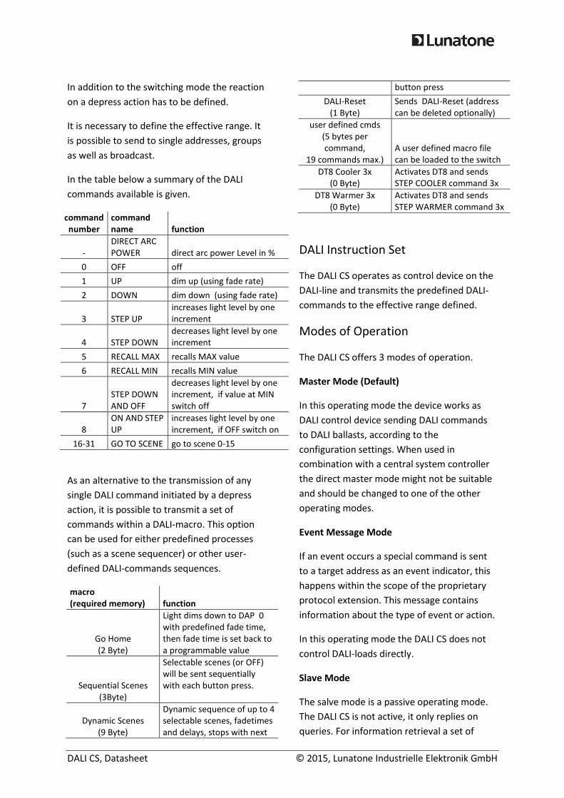
In addition to the switching mode the reaction
on a depress action has to be defined.
It is necessary to define the effective range. It
is possible to send to single addresses, groups
as well as broadcast.
In the table below a summary of the DALI
commands available is given.
command
number
command
name function
-
DIRECT ARC
POWER direct arc power Level in %
0 OFF off
1 UP dim up (using fade rate)
2 DOWN dim down (using fade rate)
3 STEP UP
increases light level by one
increment
4 STEP DOWN
decreases light level by one
increment
5 RECALL MAX recalls MAX value
6 RECALL MIN recalls MIN value
7
STEP DOWN
AND OFF
decreases light level by one
increment, if value at MIN
switch off
8
ON AND STEP
UP
increases light level by one
increment, if OFF switch on
16-31 GO TO SCENE go to scene 0-15
As an alternative to the transmission of any
single DALI command initiated by a depress
action, it is possible to transmit a set of
commands within a DALI-macro. This option
can be used for either predefined processes
(such as a scene sequencer) or other user-
defined DALI-commands sequences.
macro
(required memory) function
Go Home
(2 Byte)
Light dims down to DAP 0
with predefined fade time,
then fade time is set back to
a programmable value
Sequential Scenes
(3Byte)
Selectable scenes (or OFF)
will be sent sequentially
with each button press.
Dynamic Scenes
(9 Byte)
Dynamic sequence of up to 4
selectable scenes, fadetimes
and delays, stops with next
button press
DALI-Reset
(1 Byte)
Sends DALI-Reset (address
can be deleted optionally)
user defined cmds
(5 bytes per
command,
19 commands max.)
A user defined macro file
can be loaded to the switch
DT8 Cooler 3x
(0 Byte)
Activates DT8 and sends
STEP COOLER command 3x
DT8 Warmer 3x
(0 Byte)
Activates DT8 and sends
STEP WARMER command 3x
DALI Instruction Set
The DALI CS operates as control device on the
DALI-line and transmits the predefined DALI-
commands to the effective range defined.
Modes of Operation
The DALI CS offers 3 modes of operation.
Master Mode (Default)
In this operating mode the device works as
DALI control device sending DALI commands
to DALI ballasts, according to the
configuration settings. When used in
combination with a central system controller
the direct master mode might not be suitable
and should be changed to one of the other
operating modes.
Event Message Mode
If an event occurs a special command is sent
to a target address as an event indicator, this
happens within the scope of the proprietary
protocol extension. This message contains
information about the type of event or action.
In this operating mode the DALI CS does not
control DALI-loads directly.
Slave Mode
The salve mode is a passive operating mode.
The DALI CS is not active, it only replies on
queries. For information retrieval a set of

DALI CS, Datasheet © 2015, Lunatone Industrielle Elektronik GmbH
commands can be used, provided within the
scope of the proprietary protocol extension. It
is also possible to assign the DALI CS an
address and information can then be retrieved
via scene-retrieval.
The operating mode can be set within the
DALI Cockpit.
Additional Information and
Equipment
DALI-Cockpit – free configuration tool from
Lunatone for DALI systems
http://lunatone.at/en/dali-systems/software/
DALI-Manual http://www.dali-
ag.org/c/manual_gb.pdf
DALI USB – PC interface for DALI system. The
DALI-Cockpit can access DALI components
using the DALI USB
http://lunatone.at/en/downloads/Lunatone_
Art24138923_DALI_USB_Datasheet_EN.pdf
DALI PS – power supply for a DALI line
http://lunatone.at/en/downloads/Lunatone_
Art24033444_DALI_PS_Datasheet_EN.pdf
Contact
Technical Support: [email protected]
Requests: [email protected]
www.lunatone.com