com600 fdir configuration manual - abb configuration ... for example, press the enter key. 5...
TRANSCRIPT
Station Automation COM600 3.5FDIR Configuration Manual


Contents:
1. About this manual .................................................................................. 5
1.1. Copyrights ...................................................................................... 51.2. Trademarks .................................................................................... 51.3. General .......................................................................................... 51.4. Document conventions .................................................................. 51.5. Use of symbols .............................................................................. 61.6. Terminology .................................................................................... 71.7. Abbreviations ................................................................................. 71.8. Related documents ........................................................................ 81.9. Document revisions ....................................................................... 8
2. Introduction ............................................................................................. 9
2.1. Overview of FDIR ........................................................................... 9
3. FDIR configuration ............................................................................... 10
3.1. Building FDIR project on SAB600 ................................................ 103.2. FDIR communication structure .................................................... 103.3. FDIR single line diagram .............................................................. 123.4. FDIR Configuration Tool ............................................................... 14
3.4.1. Launching FDIR Configuration Tool .............................. 143.4.2. FDIR Configuration Tool functions ................................ 153.4.3. Specifying network settings .......................................... 153.4.4. Setting parameters for setting groups ........................... 163.4.5. Changing cross references ........................................... 173.4.6. Generating FDIR Logic Processor configuration .......... 193.4.7. Options .......................................................................... 20
3.5. Downloading FDIR configuration ................................................. 213.5.1. Downloading FDIR configuration .................................. 213.5.2. Downloading FDIR Logic Processor Project ................. 213.5.3. Downloading FDIR SAB600 configuration .................... 22
3
Station Automation COM600 3.51MRS757278
FDIR Configuration ManualIssued: 30.6.2011Version: A/30.6.2011

4
About this manual1.
Copyrights1.1.
The information in this document is subject to change without notice and should not beconstrued as a commitment by ABB Oy. ABB Oy assumes no responsibility for anyerrors that may appear in this document.
In no event shall ABB Oy be liable for direct, indirect, special, incidental, or consequentialdamages of any nature or kind arising from the use of this document, nor shall ABB Oybe liable for incidental or consequential damages arising from use of any software orhardware described in this document.
This document and parts thereof must not be reproduced or copied without written per-mission from ABB Oy, and the contents thereof must not be imparted to a third partynor used for any unauthorized purpose.
The software or hardware described in this document is furnished under a license andmay be used, copied, or disclosed only in accordance with the terms of such license.
© Copyright 2011 ABB. All rights reserved.
Trademarks1.2.
ABB is a registered trademark of ABB Group. All other brand or product names men-tioned in this document may be trademarks or registered trademarks of their respectiveholders.
General1.3.
This manual provides thorough information on FDIR configuration on Station AutomationBuilder (SAB600) and the central concepts related to it. You find instructions on buildingFDIR project on SAB600. Information in this configuration manual is intended forapplication engineers who configure the FDIR project communication structure and usethe FDIR configuration tool to set up FDIR.
Document conventions1.4.
The following conventions are used for the presentation of material:• The words in names of screen elements (for example, the title in the title bar of a
window, the label for a field of a dialog box) are initially capitalized.• Capital letters are used for the name of a keyboard key if it is labeled on the keyboard.
For example, press the ENTER key.
5
Station Automation COM600 3.51MRS757278
FDIR Configuration Manual

• Lowercase letters are used for the name of a keyboard key that is not labeled on thekeyboard. For example, the space bar, comma key, and so on.
• Press CTRL+C indicates that you must hold down the CTRL key while pressingthe C key (to copy a selected object in this case).
• Press ESC E C indicates that you press and release each key in sequence (to copya selected object in this case).
• The names of push and toggle buttons are boldfaced. For example, click OK.• The names of menus and menu items are boldfaced. For example, the File menu.
• The following convention is used for menu operations: MenuName > Menu-Item > CascadedMenuItem. For example: select File > New > Type.
• The Start menu name always refers to the Start menu on the Windows taskbar.• System prompts/messages and user responses/input are shown in the Courier font.
For example, if you enter a value out of range, the following message is displayed:
Entered value is not valid. The value must be 0 - 30 .
• You can be asked to enter the string MIF349 in a field. The string is shown as followsin the procedure:
MIF349• Variables are shown using lowercase letters:
sequence name
Use of symbols1.5.
This publication includes warning, caution, and information icons that point out safety-related conditions or other important information. It also includes tip icons to point outuseful information to the reader. The corresponding icons should be interpreted as follows.
The electrical warning icon indicates the presence of a hazardwhich could result in electrical shock.
The warning icon indicates the presence of a hazard whichcould result in personal injury.
The caution icon indicates important information or warningrelated to the concept discussed in the text. It may indicatethe presence of a hazard which could result in corruption ofsoftware or damage to equipment or property.
6
1MRS757278Station Automation COM600 3.5
FDIR Configuration Manual

The information icon alerts the reader to relevant facts andconditions.
The tip icon indicates advice on, for example, how to designyour project or how to use a certain function.
Terminology1.6.
The following is a list of terms associated with COM600 that you should be familiarwith. The list contains terms that are unique to ABB or have a usage or definition thatis different from standard industry usage.
DescriptionTerm
A physical device that behaves as its own communication nodein the network, for example, protection relay.
Device
Change of process data or an OPC internal value. Normally, anevent consists of value, quality, and timestamp.
Event
A physical IEC 61850 device that behaves as its own commu-nication node in the IEC 61850 protocol.
Intelligent Electronic Device
Series of standards specifications aiming at open connectivityin industrial automation and the enterprise systems that supportindustry.
OPC
Named data item.Property
Abbreviations1.7.
The following is a list of abbreviations associated with COM600 that you should befamiliar with.
DescriptionAbbreviation
Fault detection, fault isolation and load restorationFDIR
Human Machine InterfaceHMI
Intelligent Electronic DeviceIED
Station Automation Builder 600SAB600
Single Line DiagramSLD
7
Station Automation COM600 3.51MRS757278
FDIR Configuration Manual
Related documents1.8.
MRS numberName of the manual
1MRS756738COM600 Logic Processor User's manual
Document revisions1.9.
HistoryProduct revisionDocument version/date
Document created3.5A/30.6.2011
8
1MRS757278Station Automation COM600 3.5
FDIR Configuration Manual
Introduction2.
Overview of FDIR2.1.
FDIR on COM600 provides a feeder automation function for radial distribution networks.It gathers data from protection and control IEDs and runs a fault detection, fault isolationand load restoration (FDIR) algorithm on Logic Processor to realize automatic faultrestoration.
When a fault happens in the network, FDIR on COM600 detects the location of the faultand issues switch operation commands to isolate faulty sections from the network andto restore the electricity to the healthy sections. It also sends commands to IEDs con-trolling the switches to return to the normal pre-fault condition when a fault has beencleared.
9
Station Automation COM600 3.51MRS757278
FDIR Configuration Manual
FDIR configuration3.
Building FDIR project on SAB6003.1.
To build an FDIR project on SAB600, you need to configure a proper communicationstructure, single line diagram and use FDIR Configuration Tool to automatically generatea Logic Processor FDIR project and cross-references.
When FDIR is used in COM600, the single line diagram rep-resents only the FDIR network.
The FDIR single line diagram differs from the normal COM600 substation single linediagram. The FDIR single line diagram currently only uses the Circuit Breaker symbolto represent a switch, the Outfeeder symbol to represent load, and Infeeder and Busbarsymbols to represent source. Other symbols are not used in the FDIR single line diagram.
FDIR communication structure3.2.
The IEDs in the network need to be configured in the SAB600 communication structure.For more information on the configuration, refer to the related communication protocolconfiguration manual. Figure 3.2-1 shows an example of a typical IED configuration.
10
1MRS757278Station Automation COM600 3.5
FDIR Configuration Manual

IED_configuration
Figure 3.2-1 IED configuration
To implement FDIR, certain settings must be configured properly to enable the automationrestoration logic.
Table 3.2-1 Data objects required for FDIRMandatory/optionalDescriptionData object
MandatoryThis data object is used to determineif the switch is in Remote or Localemode.
LLN0/Loc
11
Station Automation COM600 3.51MRS757278
FDIR Configuration Manual
Mandatory/optionalDescriptionData object
OptionalUsed to change setting group on theIED. In the FDIR configuration tool,user can set the load level for differentsetting groups. During FDIR opera-tion, system will check the new loadand change the setting group on theIED.
LLN0/Act1SG
LLN0/Act2SG
LLN0/Act3SG
LLN0/Act4SG
LLN0/Act5SG
LLN0/Act6SG
MandatoryUsed to read switch status and oper-ate the switch.
CSWI/Pos
MandatoryThe current measurement through theIED, which is used to calculate theload in the network.
MMXU/A
MandatoryThe lock out signal from the IED. Thissignal and switch open fromCSWI\Pos will contribute a fault condi-tion in FDIR.
RREC/LO
FDIR single line diagram3.3.
Single line diagram should be built to map the actual distribution network. In FDIR threeelements are used to describe distribution network: Source, Switch and Load. In FDIRsingle line diagram, Infeeder or Bus Bar should be used to represent Source, CircuitBreaker to represent Switchers, and Outfeeder to represent Load. There should alwaysbe an Outfeeder (Load) connection between any two switches.
All objects of FDIR should be placed below one voltage level. All devices can be placedunder one bay to create a simple network. It is recommended to configure a bay for eachsubstation, configure a substation network under each bay and in Voltage Level to con-figure connections among substations.
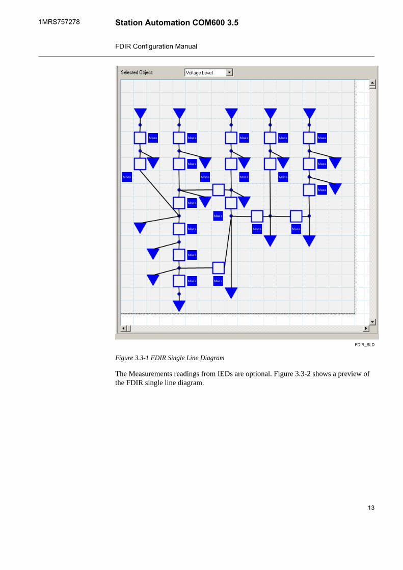
Figure 3.3-1 shows a typical single line diagram with 5 Sources, 15 Loads and 20 Switchesin the network.
12
1MRS757278Station Automation COM600 3.5
FDIR Configuration Manual
FDIR_SLD
Figure 3.3-1 FDIR Single Line Diagram
The Measurements readings from IEDs are optional. Figure 3.3-2 shows a preview ofthe FDIR single line diagram.
13
Station Automation COM600 3.51MRS757278
FDIR Configuration Manual

FDIR_SLD_preview
Figure 3.3-2 Preview of FDIR single line diagram
FDIR Configuration Tool3.4.
Launching FDIR Configuration Tool3.4.1.
To launch FDIR Configuration Tool:1. In the Substation Structure, right-click the Voltage Level node in the Substation
Structure.2. Select FDIR Tool, see Figure 3.4.1-1.
14
1MRS757278Station Automation COM600 3.5
FDIR Configuration Manual

launch_FDIR_configuration_tool
Figure 3.4.1-1 Launch FDIR Configuration Tool
The FDIR Tool opens.
FDIR Configuration Tool functions3.4.2.
FDIR Configuration Tool can be used for the following functions:• enabling device in the network and specifying capacity limit• specifying group setting• generating FDIR Logic Processor configuration• changing cross references
Specifying network settings3.4.3.
Figure 3.4.3-1 shows the Network setup tab in FDIR Configuration Tool, in which youcan enable or disable a device in the network and change the capacity limit of sourcesand switches.
15
Station Automation COM600 3.51MRS757278
FDIR Configuration Manual

FDIR_network_setup
Figure 3.4.3-1 FDIR Configuration Tool - Network Setup
On the Switch tab, you can enable or disable the switch to be included in the FDIR net-work. You can also change the capacity limit on the switch. FDIR also supports singlephase switch in the network. When single phase is selected, you can select the switchfor phase B and phase C. Phase B and Phase C switch should be disabled from the FDIRnetwork.
On the Source tab, you can enable or disable the source to be included in the FDIR net-work. Also you can change the capacity limit on the source.
On the Load tab, you can enable or disable the load to be included in the FDIR network.
Setting parameters for setting groups3.4.4.
In the Group Settings tab, you can set parameters for setting groups, the range toactivate the setting group, a data object to read the current setting group number, and adata object to send a command to change the setting group.
16
1MRS757278Station Automation COM600 3.5
FDIR Configuration Manual

FDIR_setting_groups
Figure 3.4.4-1 Protection Setting Group
Changing cross references3.4.5.
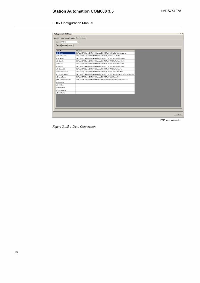
In the Data Connection tab, you can view and manually change the cross reference ofFDIR variables.
The Variable column contains a list of variables used in the FDIR logic. The OPC itemcontains the mappings for the variables in the OPC servers of the communication structure.The data connection mapping is a table view of the logic processor cross reference, whichis generated by the FDIR configuration tool. The FDIR configuration tool uses dataconnection information in the substation structure to find the corresponding switch dataobject for the variables. Any change on the data connection table is reflected on the logicprocessor cross reference.
To change the cross reference:1. Select the row and click Change.2. The Select Cross Reference dialog opens with a list of available data objects to
select, see Figure 3.4.5-2.3. Select any data object on the list, and click OK.
17
Station Automation COM600 3.51MRS757278
FDIR Configuration Manual
FDIR_data_connection
Figure 3.4.5-1 Data Connection
18
1MRS757278Station Automation COM600 3.5
FDIR Configuration Manual

select_cross_reference
Figure 3.4.5-2 Select Cross Reference
Generating FDIR Logic Processor configuration3.4.6.
Another result of FDIR Configuration Tool is the Logic Processor cross reference. Inthe communication structure, right-click Logic Processor and select Cross References.Cross Reference Tool opens between OPC Server data objects and Logic Processorvariables automatically generated by FDIR configuration.
19
Station Automation COM600 3.51MRS757278
FDIR Configuration Manual
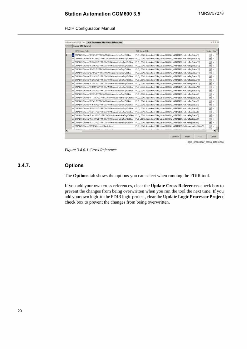
logic_processor_cross_reference
Figure 3.4.6-1 Cross Reference
Options3.4.7.
The Options tab shows the options you can select when running the FDIR tool.
If you add your own cross references, clear the Update Cross References check box toprevent the changes from being overwritten when you run the tool the next time. If youadd your own logic to the FDIR logic project, clear the Update Logic Processor Projectcheck box to prevent the changes from being overwritten.
20
1MRS757278Station Automation COM600 3.5
FDIR Configuration Manual

options.png
Figure 3.4.7-1 Options
Downloading FDIR configuration3.5.
Downloading FDIR configuration3.5.1.
The following steps are required for downloading FDIR configuration to COM600:• 3.5.2, Downloading FDIR Logic Processor Project• 3.5.3, Downloading FDIR SAB600 configuration
Downloading FDIR Logic Processor Project3.5.2.
FDIR Configuration Tool will generate the FDIR Logic Processor project automatically.
To download FDIR Logic Processor project:1. In the communication structure, select Logic Processor IED.2. Right-click the IED and select Logic Editor to launch Logic Processor Editor, see
Figure 3.5.2-1.
21
Station Automation COM600 3.51MRS757278
FDIR Configuration Manual

launch_logic_editor
Figure 3.5.2-1 Launch Logic Editor
The FDIR project opens in a separate Logic Processor Editor window.3. In Logic Processor Editor, select Device to open the device dialog.4. In the device dialog, select the default device. For more information, see Logic
Processor User Manual.5. Select Online\Login to download the FDIR Logic Processor project.
Downloading FDIR SAB600 configuration3.5.3.
After you have downloaded the FDIR Logic Processor project, download FDIR SAB600configuration to COM600 with updated cross references. The FDIR configuration isdownloaded in the same way as other SAB600 projects.
To download the FDIR SAB600 configuration:1. In the communication structure, select Gateway.2. Right-click the Gateway object and select Management.3. In the Management dialog, select the Reset check-box.4. Click the Update and reload configuration button.
22
1MRS757278Station Automation COM600 3.5
FDIR Configuration Manual

Contact us
1MR
S75
7278
A/3
0.6.
2011
© C
opyr
ight
201
1 A
BB
. All
right
s re
serv
ed.
ABB OyDistribution AutomationP.O. Box 699FI-65101 VAASA, FINLANDTel. +358 10 22 11Fax. +358 10 224 1094
ABB Inc.Distribution Automation655 Century PointLake Mary, FL 32746, USATel: +1 407 732 2000Fax: +1 407 732 2335
www.abb.com/substationautomation