colloids a - yonsei universitychem.yonsei.ac.kr/~mhmoon/pdf/papers/15_colloid.pdf · colloids and a...
TRANSCRIPT

COLLOIDS AND A
Colloids and Surfaces SURFACES A: Physicochemical and Engineering Aspects 113 (1996) 215-228 E L S E V I E R
Influence of accumulation wall and carrier solution composition on lift force in sedimentation/steric field-flow fractionation
P. Stephen Williams, Myeong Hee Moon 1, j. Calvin Giddings * Field-Flow Fractionation Research Center, Department of Chemistry, University of Utah,
Salt Lake City, Utah 84112, USA
Received 12 September 1995; accepted 20 March 1996
Abstract
Sedimentation/steric field-flow fractionation is an established analytical technique for characterizing particulate materials by size in the approximate diameter range 1-100 ~tm. Particles are eluted through a thin, parallel-walled channel by a flow of a carrier liquid while a centrifugal field is applied across the thin dimension perpendicular to the flow. During elution, particles are driven towards equilibrium positions between the channel walls where the force due to the applied field is balanced by hydrodynamic lift forces. These lift forces are not yet fully characterized, and calibration using latex standards is at present a necessary prerequisite for size characterization of unknown materials. A greater understanding of the forces involved will ultimately eliminate this need for calibration.
The elution of latex standards under various field strength and carrier flow rate regimes yields information on lift force as a function of particle size, flow velocity, position within the channel, and any other controllable system property. The work presented here examines the influence of channel wall and carrier solution composition (ionic strength and pH) on overall lift. It is shown that the observed lift may be described as the sum of a force due to the effects of fluid inertia, an empirical near-wall lift force inversely dependent on particle distance from the wall, and a force due to electrostatic repulsion.
Keywords: Electric double layer; Electrostatic repulsion; Field-flow fractionation; Hydrodynamic lift force; Inertial lift force; Sedimentation
1. Introduction
Field-flow fract ionation ( F F F ) comprises a family of related elution techniques used for sepa- rating and characterizing macromolecular , colloi- dal, and particulate materials having grain sizes from 10 -3 to 102~tm [1,2] . Separat ion of the components (either in solution or in suspension, as the case may be) is effected within a thin, closed
* Corresponding author. 1 Current address: Department of Chemistry, Kangnung
National University, Kangnung, Kangwon-Do, Korea, 210-702.
0927-7757/96/$15.00 © 1996 Elsevier Science B.V. All rights reserved PII S0927-7757 (96) 03669-2
channel of rectangular cross-section. The material to be analyzed is driven across the thin channel dimension towards the so-called accumulat ion wall by interaction with some externally applied field. A flow of carrier liquid then drives the different components along the channel length to the outlet and generally on to a detector and sometimes a device to collect fractions. The geometry of the channel induces a parabolic velocity profile in the carrier liquid across the thin dimension; the differ- ing distributions of the various components within this velocity profile lead to their separation and differential elution. Elution times (generally called
216 P.S. Williams et al./Colloids' Surfaces A." Physicochem. Eng. Aspects' 113 (1996) 215-228
retention times) typically range from a few minutes to a few tens of minutes.
In the so-called normal mode of FFF, the par- ticles to be separated are sufficiently small that a dynamic equilibrium is set up between their field- induced motion towards the accumulation wall and their back-diffusion from the resultant high concentration at the wall. In tile steric mode, the mode of interest in the present work, the particles are of such a large size (generally greater than 1 gm) that Brownian motion brings about negligi- ble back-diffusion. Rather, the particle motion towards the accumulation wall will be opposed by hydrodynamic lift forces [3-5] and possibly other forces such as electrostatic repulsion or electroki- netic lift as investigated below.
Equilibrium between opposing forces is generally achieved when the particles are relatively close to the accumulation wall. The larger particles then protrude further into faster flowing streamlines than do the smaller ones, and are swept through the channel more quickly. Steric FFF is therefore characterized by larger particles eluting before smaller ones [6], which is opposite to the elution order in the normal mode.
The work described here was carried out using steric FFF with a sedimentation driving force, constituting the subtechnique sedimentation/steric field-flow fractionation (Sd/StFFF). The sedi- mentation field is obtained by wrapping the thin channel around the inside of a specially designed centrifuge basket with the flow of carrier being conveyed to and from the channel via rotating seals. The retention volume (i.e. the product of retention time and the volumetric flow rate of the carrier solution) of particles in Sd/St FFF has been found to be influenced by the external field strength (or sedimentation force), carrier flow rate, particle size, and particle density [7-10]. The work pre- sented here shows that retention volume is also influenced by the composition of both the accumu- lation wall and the carrier solution. It is not presently possible to predict retention volume because of the complicated and not fully charac- terized nature of the forces opposing the field- induced force on the particles. Because these forces are not fully understood, the equilibrium position relative to the accumulation wall cannot be pre-
dicted and it is thus not possible to predict particle velocity within the channel. A better understanding of the forces acting on eluting particles will make it possible to characterize such particles (especially with respect to size, size distribution, and density) without the need for calibration. Such knowledge will also improve our understanding and control of the capture of particles in flowing fluids by surfaces, which leads to particle adhesion and consequent changes (wanted or unwanted) in the nature of the surface.
2. Theory
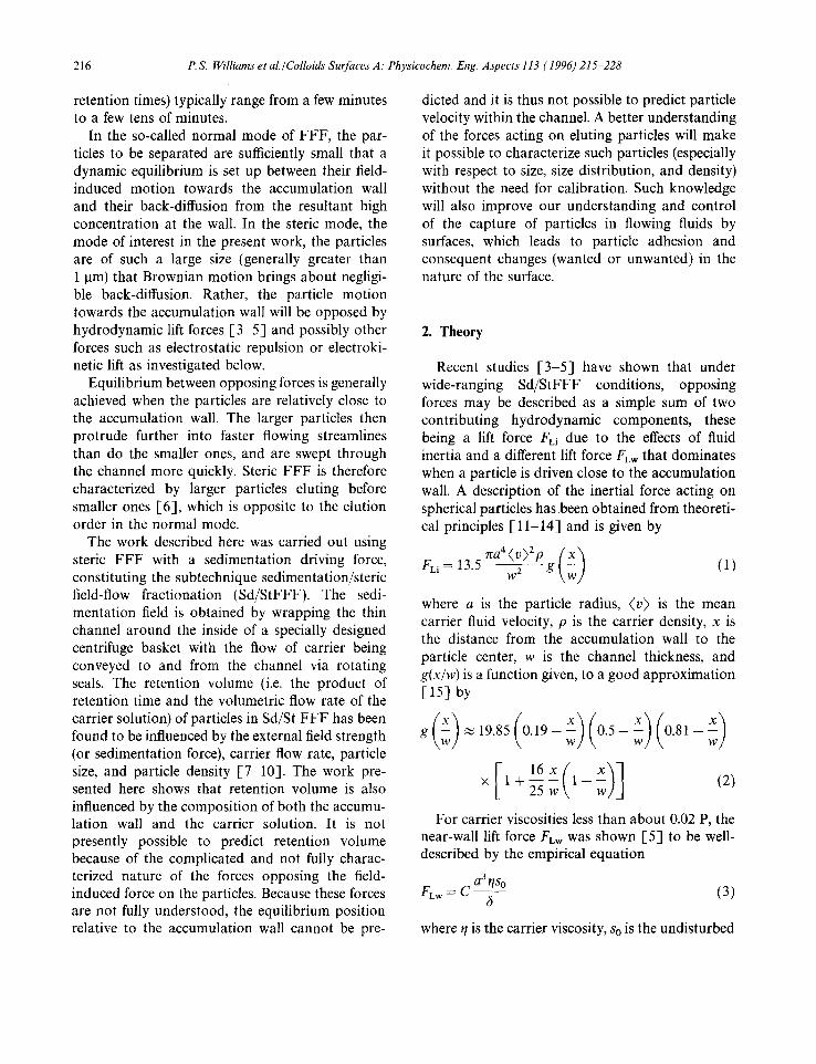
Recent studies [3-5] have shown that under wide-ranging Sd/StFFF conditions, opposing forces may be described as a simple sum of two contributing hydrodynamic components, these being a lift force FL: due to the effects of fluid inertia and a different lift force FLw that dominates when a particle is driven close to the accumulation wall. A description of the inertial force acting on spherical particles has.been obtained from theoreti- cal principles [ 11-14] and is given by
na4(v)Zp {x '~ FLi =13"5 ~5 g ~ w ) (1)
where a is the particle radius, (v) is the mean carrier fluid velocity, p is the carrier density, x is the distance from the accumulation wall to the particle center, w is the channel thickness, and g(x/w) is a function given, to a good approximation [15] by
[ 16X(,w) ] x 1 + ~-~ w
For carrier viscosities less than about 0.02 P, the near-wall lift force Few was shown [5] to be well- described by the empirical equation
a 3 qs o F L w = C - (3)
6
where q is the carrier viscosity, So is the undisturbed

P.S. Williams et al./Colloids Surfaces A: Physicoehem. Eng. Aspects 113 (1996) 215--228 217
shear rate of the carrier solution at the accumula- tion wall, 6 is the distance between the particle surface and the wall (equal to x - a), and C is a dimensionless empirical coefficient. For carrier vis- cosities significantly greater than 0.02 P, a higher- order dependence of FEw on r/ was apparent.
When entrained in the flowing carrier solution, a particle is driven to an equilibrium height above the accumulation wall at which the sedimentation force IF~I is exactly counterbalanced by opposing forces (here assumed to be the sum of the two contributions to lift force), so that
IFoL= FL= FLw + FLi (4)
Because FL is dependent upon the particle position, this equation yields the particle coordinate x. The particle velocity vp at this position does not exactly correspond to the undisturbed carrier velocity v(x) at the position of the particle center, but to a somewhat reduced velocity [ 16]. The ratio of the velocity of the particle Vp to that of the fluid v(x) is predicted to be a function, f(6/a), of the ratio 6/a. The particle velocity Vp is thus given by
sedimentation force is calculated from the equation
IF~[ =~rca2GAp (7)
where Ap is the density difference between the particle and the carrier fluid, and G is the centrifu- gal acceleration given by o~2ro, where ~ is the angular velocity of the centrifuge and r 0 is the radius of the channel. The near-wall lift force is then assumed to be the excess force required to balance Eq. (4). The form of Eq. (3) was obtained using multiple linear regression of parameters for extensive sets of experimental measurements.
Since the near-wall lift force plays such a major role in determining equilibrium positions of par- ticles within FFF channels, it is important to elucidate its mechanism. It is expected that the consideration of the effects of a wider range of parameters will contribute to our understanding. To this end, the influence of the channel wall material and of the ionic strength and pH of the carrier solution on the near-wall lift force have been examined.
vP = f(5/a)v(x) = 6 f (6 /a) (v ) X ( 1 - x (5) 3. Experimental
in which v(x) has been replaced by the parabolic velocity function and where x = a + 6. The function f(6/a) approaches zero as 5 / a ~ O and quickly approaches unity as the particle moves away from the wall.
The retention ratio R is defined by
R - ( v ) - 6f(fi/a) 1 - (6)
Experimentally, R is most readily obtained as the ratio of the void time t o (the elution time of a non- retained species) to the retention time tr. It is also equal to the channel void volume divided by the measured retention volume.
The procedure for determining the value of the contribution FEw for a given set of conditions is as follows. A measurement of R for a given particle standard yields, via solution of Eq. (6), equilibrium values for 5 and x. The contribution ELi is calcu- lated from theory using Eqs. (1) and (2), and the
The sedimentation FFF syste.m used in this study has been described previously [4,5]. It has the same design as the model S101 colloid/particle fractionator from FFFractionation, LLC (Salt Lake City, UT). The channel accumulation wall is made of polished Hastelloy-C. The channel outline was cut from a Mylar strip 127 gm thick, and had a breadth b of approximately I cm and a tip-to- tip length Ltt of 90 cm. The Mylar strip was used as a spacer between the two parallel channel walls. The void volume of the channel was determined to be 1.18 ml by elution of a non-retained sample of sodium benzoate. For some experiments, the accumulation wall was coated with Teflon depos- ited from solution (3M Co., Minneapolis, MN); for some it was covered by Kapton polyimide tape (CHR Industries, New Haven, CT); and for others it was covered with Mylar. The void volume for the Mylar-coated channel was determined to be 0.98 ml. The effective channel thickness was appa- rently reduced due to compression of ~he Mylar
218 P.S. Williams et al./Colloids Surfaces A: Physicochem. Eng. Aspects 113 (1996) 215-228
beneath the channel spacer, although there is in addition some uncertainty in b due to the difficulty of aligning the spacer between the channel walls. The Teflon coated and polyimide coated channels may also have had somewhat reduced thicknesses compared to the bare Hastelloy-C channel.
Several different carrier solutions were used in this study. All were made up using doubly distilled, deionized water. For the examination of the influ- ence of channel wall composition on lift force, a 0.1% (w/v) solution of FL-70 detergent (Fisher Scientific, Fairlawn, NJ) with 0.02% sodium azide added as a bactericide was used. This carrier composition was used in some previous lift force studies I-4,5] and is commonly used for latex size analysis by FFF. The ionic strengths of the FL-70 solutions were calculated on the basis of the com- position as provided by the manufacturer, this being 3.0% oleic acid, 3.0% sodium carbonate, 1.8% Tergitol (which is a mixture of polyoxyethyl- ene alcohols functioning as a non-ionic surfactant), 1.4% tetrasodium EDTA, 1.3% triethanolamine, and 1.0% polyethylene glycol, made up in water.
For the study of the effects of ionic strength on the lift force, two different carrier solution/accumu- lation wall combinations were employed. A series of carrier solutions containing 0.1% (w/v) of Triton X-100 (a non-ionic surfactant from J.T. Baker Chemical Co. Phillipsburg, NJ) was used with the bare Hastelloy-C accumulation wall. Carrier solu- tions of different ionic strength were made by the addition of sodium nitrate. The pH was fixed at 8.6 for all salt concentrations by adding a small amount of sodium hydroxide. Both the sodium nitrate and sodium hydroxide were considered in the calculation of solution ionic strengths. A series of solutions of sodium dodecyl sulphate (SDS) of differing concentrations was used in conjunction with the Mylar-covered accumulation wall. It was found that resolution of the different particle sizes was relatively poor when SDS carriers were used with a Hastelloy-C accumulation wall.
The standards used in this study were polysty- rene latex beads (Duke Scientific, Palo Alto, CA) with nominal diameters of 20.49, 19.58, 15, 9.87, 7.04, and 5.002 gm (hereafter described as 20, 15, 10, 7, and 5 ~tm, respectively). All experiments were carried out using the stopless flow-injection
method. Mixtures of the five different polystyrene latex beads in suspension were injected directly into the carrier flow near the channel inlet while the centrifuge was spinning at a desired rate.
The carrier fluid was driven by a Kontron LC pump (Kontron Electrolab, London, U.K.) for flow rates of less than 10mlmin -1, and by an FMI Lab pump model QD-2 (Fluid Metering, Inc., Oysterbay, NY) for higher channel flow rates and for flushing the channel at about 30 ml min- t. The eluted sample was tracked by a Spectroflow moni- tor SF770 (Kratos Analytical Instruments, Westwood, NJ) UV-VIS detector set at 300 nm. An OmniScribe strip chart recorder (Houston Instrument Corp., Austin, TX) was used for record- ing the detector response. All experiments were conducted at an ambient laboratory tempera- ture of 23 __+ 1 °C; carrier densities and viscosities were accordingly assumed to equal those of pure water at 296 K (i.e. 0.998 gm1-1 and 0.933 cP, respectively).
4. Results and discussion
4.1. Composition of accumulation wall
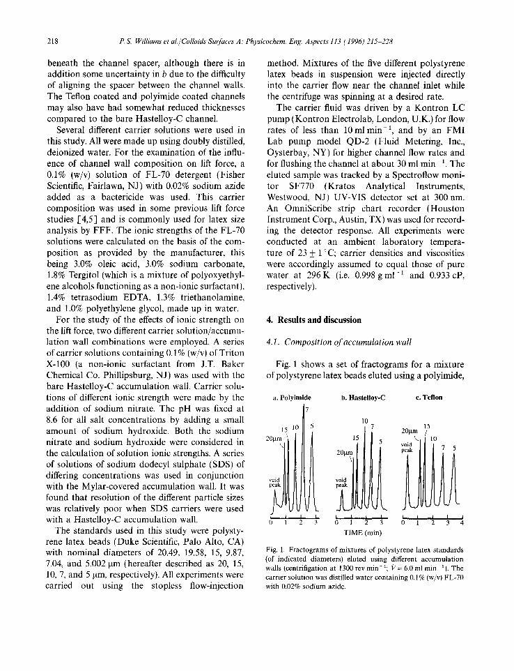
Fig. 1 shows a set of fractograms for a mixture of polystyrene latex beads eluted using a polyimide,
a. P o l y i m i d e
7
15 10 5
20..( i
1 ; 1
b. Hastelloy-C c. Teflon
L
3
10 7
15
20~tm\ l
void peak
L . i I 0 3
TIME (rain)
201am \
void
i I
0 1
15
lO
i I 1 2 3 4
Fig. 1. Fractograms of mixtures of polystyrene latex standards (of indicated diameters) eluted using different accumulation wails (centrifigation at 1300 rev min- 1; 17 = 6.0 ml rain 1). The carrier solution was distilled water containing 0.1% (w/v) FL-70 with 0.02% sodium azide.

P.S. Williams et al./Colloids Surfaces A: Physicochem. Eng. Aspects 113 (1996) 215--228 219
a bare Hastelloy-C, and a Teflon-coated accumula- tion wall. In all cases, the carrier was a 0.1% (w/v) FL-70 with a 0.02% sodium azide solution with a flow rate of 6.0 ml min- 1. The centrifuge was run at 1300revmin -1. The separation time ranges from less than 3 min for the polyimide channel to about 3.5 min for the Teflon coated channel. This suggests that the near-wall lift force is largest for polyimide and smallest for Teflon. It was men- tioned that the channel thickness was uncertain for the channels having coated accumulation walls. The apparent increase in lift force for the poly- imide-coated channel compared to the bare Hastelloy-C channel may be due to a reduction in channel thickness [3] . However, the apparent reduction in lift force for the Teflon-coated channel (compared to Hastelloy-C) cannot be explained in this way.
At least 40 determinations of Few were made in the manner described earlier for each of the channel wall materials (assuming w = 127 gm for all). In each case, FLw had a dependence on a, So, and 6 consistent with Eq. (3). Values of the coefficient C were determined to be 1.9 x 10 -4, 0.93 x 10 -4, and 0.45 X 10 -4 for polyimide, Hastelloy-C, and Teflon, respectively, although as explained above, there is more uncertainty associated with the values for the coated walls.
The nature of the accumulation wall apparently influences the near-wall lift force quite strongly. Electrostatic and van der Waals interactions of particles with the accumulation wall are known to influence retention times in normal-mode FFF [17,18]. Electrostatic interactions have also been considered to account qualitatively for the varia- tion of retention times in the steric mode [ 19]. We shall examine these interactions quantitatively for their possible influence on retention time in the steric mode.
The electrostatic repulsive force F r caused by the surface charge interaction between a particle and a plane wall is given by [20]
Fr = BK exp(-- ~:3) (8)
where the constant B is given by
/ kT~ 2 , (egtt'~ (e~-t2) B= 1 6 e a ~ - ) t a n n ~ 4 ~ ) t a n h 4 ~ (9)
where e is the static dielectric constant of the fluid, k is the Boltzmann constant, e is the electronic charge, and 7Jl and ~2 are the surface potentials of the sphere and the wall material. The constant rc in Eq. (8) is the reciprocal of the double-layer thickness given by Gouy-Chapman theory as [21]
K_ 1 (ekT~ 1/2 = \2 - -~} (10)
where I is the ionic strength of the carrier solution. Eqs. (8) and (9) require the double-layer thickness ~ - i to be much smaller than the gap distance 3, and 6 to be much smaller than the particle radius a (i.e. ~ca >> to8 >> 1).
The van der Waals attractive force F,, in the limiting case of 3 << a, is given by [22,23]
A132a F a - - 682 (11)
where A132 is the effective Hamaker constant for materials 1 and 2 interacting across medium 3. This constant A132 is related to A131 and A232 by the approximation [24]
A132 ~ ! ~ (12)
When the gap distance 8 is larger than about 0.10 gin, the attractive force in Eq. (11) is reduced due to the finite time for propagation of electro- magnetic radiation between the particle and the wall. The modification of the force above this limit is not considered because the magnitude of attrac- tive forces above this range are, in fact, negligible. The Hamaker constants and surface potentials of materials used in this study were obtained from Ref. [17] and are listed in Table 1.
Figs. 2(a) and 2(b) show the attractive and repulsive contributions and their sum, the net
Table 1 Hamaker constants (for interaction across an aqueous medium) and surface potentials of the materials used in this study
Materials Hamaker constant Surface potential 1020 × A131 (j) ~u (mV)
Polystyrene 0.95 - 80 Polyimide 5.0 - 25 Teflon 0.33 - 10

220 P.S. Williams et al./Colloids Surfaces A." Physicochem. Eng. Aspects 113 (1996) 215-228
d o a b l e layer
6 ; ~' repuls ive a . P o l y i m i d e
force / _ ~ J ~ , wal l -e f fec t lift force
4 f \ ~ \ /---16.8 cm/s
.94 2
° - 1 , ) < I - I . ox° .I
~'~ -2 , , I , i . . . . , . . . . ,,,,~ . . . . . . . .
× b. T e f l o n
/ repuls ive 4 - P ~ fdrce , wal l -e f fec t lift force
~ N : k /---16.8cm/s I N ' \ / f - 7.87
i;gtr.e
"] [, /"--at tract ive !It [../.1 force ~2
, , , I , r ~ , , , , . . . . . . . . , . . . . . . . .
0.001 T 0.01 o. 1 1.0 double layer 5 ([tm)
Fig. 2. The electrostatic repulsive force Fr, the van der Waals attractive force Fa, their sum FDLVO, and the empirical near- wall lift force FLw plotted versus the gap 6 between 10 ~tm particle and (a) the polyimide wall, and (b) the Teflon wall. The curves for electrostatic forces are based on I = 4.29 x 10 -3 M.
interactive force FDLV o, between a 10 pm diameter polystyrene particle and the polyimide and Teflon surfaces, respectively, suspended in the 0.1% (w/v) FL-70 and 0.02% sodium azide carrier solution. The ionic strength I of the carrier solution was calculated to be 4.29 × 10 3 M, with the FL-70 contributing 1.22 x 10 -3 M and the sodium azide 3.07 × 10 -3 M. Assuming that e for water at the experimental temperature was equal to 78.54e0, where eo is the permittivity of free space, the double-layer thickness was calculated by Eq. (10) to be 4.63 nm. The position of the double layer is indicated in each of the figures. Also included in each figure is the range of ,5 (designated 6oxp) determined for the sets of experimental measure-
ments. In the case of polyimide, 6 ranged from 0.027 to 0.60 pm, and for the Teflon-coated chan- nel, 6 ranged from 0.008 to 0.14 ~tm. For compari- son with the theoretical interactive forces with both polyimide and Teflon, the empirical near-wall lift force FLw is plotted for mean carrier fluid velocities of 3.94, 7.87, and 16.8 cms -1. These curves were calculated using Eq.(3) with the respective coefficients C reported earlier. For the range of experimental conditions studied, we observe that the empirical lift force is in all cases far greater than any predicted net repulsion due to particle-wall interactions. We conclude that simple electrostatic repulsion between particles and channel walls cannot account for the lift forces involved with the steric migration of particles in these systems.
4.2. Ionic strength of carrier solution
Fractograms of the latex bead mixture eluted with 0.1% Triton X-100 carrier solution are shown in Fig. 3. In the case of fractograms (b) and (c), the carrier was modified by the addition of a small amount of N aO H to set the pH at 8.6 and sodium nitrate to alter the ionic strength to 3.3 × 10 - 4 M and 3.0 × 10 -2 M, respectively. Fractogram (a) was obtained without the addition of either NaOH
a. I = 5 .9 x IO-~M b. I = 3.3 x IO-4M
10
20Bm void peak
I I o 0.5 1.o
10 15
void
l L 1 1 0 0.5 1.0 1.5
TIME (min)
c. I = 3.0 × lO-2M
10 15 5
20Bm
void ~.~ peak
I I I I I 0 0.5 1.0 1.5 2.0
Fig. 3. Fractograms of polystyrene latex standards eluted at 1300 rev min - 1 and 17 = 8.25 ml rain I using 0.1% Triton X-100 carrier solutions. For fractograms (b) and (c) the carrier contained NaOH in order to fix the pH at 8.6 and sodium nitrate to modify the ionic strength. The channel accumulation wall was of Hastelloy-C.

P.S. Williams et aL/Colloids Surfaces A: Physicochem. Eng. Aspects 113 (1996) 215 228 221
or sodium nitrate. The ionic strength of this carrier was estimated as 5.9 x 1 0 - 6 M by a comparison of the conductivity measurements on the different carrier solutions, and the pH was found to be about 5.2-5.3. The carrier flow rate in each case was set at 8.25 ml min -1 and the centrifuge rota- tion rate at 1300 rev min-1. The accumulation wall was bare Hastelloy-C. The retention time for the different latex beads is seen to increase with increase of carrier ionic strength, and at the same time the resolution improves. The peaks for the 7 and 5 ~tm particles are only partially resolved at the lowest ionic strength. (The void peak in (c) appears negative due to the difference in relative absorptivity between the carrier solution and the injected sample solution.)
Two other carrier solutions were also used in this study, one containing only Triton X-100 and sufficient N a O H to set the pH at 8.6 ( I = 3.8 x 10 -5 M), and another containing, in addi- tion, sodium nitrate with a total ionic strength of 3.1 × 10 -3 M. The polystyrene standard mixture was eluted using all five carrier solutions under many different field strength and flow rate combi- nations. Treatment of the results in the manner described earlier yielded differing values for the coefficient C of the near-wall lift force as described by Eq. (3). The results are listed in Table 2A. Close to 70 data points were taken into consideration for the determination of each value of C. The value of C, and therefore the strength of the near-wall contribution to the overall lift force, is seen to decrease with increase of carrier ionic strength. The variation in this empirical lift force is not great, changing by a factor of about two for a five- thousand fold change in I. We found that the fit to the model described by Eq. (4), judged by the sum of the squares of the residuals, improved with increase of I.
Further insight into what seem to be competing mechanisms for the lift force close to the accumula- tion wall may be gained by plotting selected data in various ways. For example, Fig. 4 shows data for 10 ~tm particles plotted as log(g) versus log(I) for five different carrier flow rates. Except for the points corresponding to the highest flow rate and two lowest ionic strengths, the data appear to show an understandable trend. At the lowest flow
Table 2 Values of the dimensionless coefficient C of the near-wall lift force (see Eq. (3)) obtained for carrier solutions of different ionic strength
A. 0.1% Triton X-tO0 carrier solution/Hastelloy-C accumula- tion wall
I ~-1 pH 104C (M) (ktm)
5.9 × 10 -6 0.12 5.2 3.2
3.8 × 10 -5 0.049 8.6 2.5
3.3 x 10 -4 0.016 8.6 2.1
3.1 × 10 3 0 .0054 8.6 1.8
3.0 × 10 -2 0.0018 8.6 1.7
B. SDS carrier solution/Mylar accumulation wall
I K - 1 1 0 4 C
(M)
3.0 × 10 -6 0.18 3.1 3.0 x 10 4 0.018 1.5 3.0 x 10 3 0.0055 1.1
-3
-4
_5 I
- 6 -
- 7
-7
I I I I I
I
o • o o o
0
A
Cl • 12.80 m L / m i n o 8 .25 • 5 .75 A 4 .35 o 3 .00
I [ I I I I -6 -5 -4 -3 -2 -1 0
Log 1 (M)
Fig. 4. Data for 10 ktm particles eluted with 0.1% Triton X-100 carrier solutions of five different ionic strengths plotted in the form of log(h) versus log(l) for five different carrier flow rates.
rate (3.0 ml min - 1), the equilibrium 6 decreases as the ionic strength is raised (6 varies approximately with 1-°'2). The dependence of 6 on 1 decreases as the flow rate is increased. This behavior may be explained as follows. At the lower flow rates, hydrodynamic lift forces may be small enough such that the equilibrium 6 is comparable to x 1. If electrostatic repulsion contributes significantly to

222 P.S. Williams et al./Colloids Surfaces A: Physicochem. Eng. Aspects 113 (1996) 215-228
the overall lift force, then we would expect 5 to decrease (along with x -a) with increase of I. At higher flow rates, the equilibrium 5 is larger, proba- bly determined by a balance between the field- induced force and the larger hydrodynamic contri- butions to the lift force. The decreasing dependence of 5 on I with increase in (v) is to be expected if the dominating hydrodynamic lift forces at the equilibrium c~ are independent of I. The influence of double-layer repulsion on the equilibrium 6 would rapidly decline as hydrodynamic effects come into play (see Eq. (8), which describes the exponential decline in Fr with increasing 6). This would also explain the improved fit to the model of Eq. (4) for higher ionic strengths.
To examine the above explanation, the data of Fig. 4 are replotted in Fig. 5 in the form of log(~c6) versus log(I), where ~c6 is the ratio of 6 to double- layer thickness ~c 1. The calculated values for double-layer thickness are tabulated in Table 2A for each ionic strength used in this set of experi- ments. They range from 0.12 gm at the lowest ionic strength (far left side of Fig. 5) to 0.0018 gm at the highest. The slopes of the plots are positive. This is because ~c -1 varies with I o.s according to Eq. (10), so that
d log(to6) d log(5) - - + 0 . 5 ( 1 3 )
d log(I) - d log(I)
At the lower ionic strengths and lower flow rates considered, log(~cS) is seen to fall to the region of
zero and below. The distance 6 is therefore compa- rable with tc -1. Certainly at such narrow gap spacings we would expect double-layer repulsion to contribute significantly to the total lift force.
Another observation that may be made from either Figs. 4 or 5 concerns the dependence of 6 on (v) with a change of I, all other parameters remaining constant. At the highest ionic strength considered, 5 varies approximately with the square of (v), which suggests that an inertial mechanism dominates FL. At the lowest ionic strength, where double-layer repulsion is expected to play some role in overall lift, the dependence falls to about (v) o.8 (ignoring the outlying point at highest (v)). This decreasing dependence on (v) is to be expected since the empirical lift force FLwvaries linearly with (v) and the double-layer interaction should be independent of (v). The dependence of 6 on the square of (v) at high I is, however, at odds with the observed dependence of & on a. A set of plots of log(6) versus log(a) corresponding to the five ionic strengths at a flow rate of 5.75mlmin -1 and 1800revmin -1 is shown in Fig. 6. The slopes of these plots range from - 1.1 to +0.1, corresponding to I changing from 5.9 × 10 6 M tO 3.0 x 10⁻²M, respectively. The lack of dependence on 6 on a observed for the higher I is consistent with a dominant lift force that varies with a 3, as shown by FEw in Eq. (3). A lift force dominated by the inertial contribution would result in a slope approaching unity. As
J
5
4-
3-
2-
1-
0 -
- 1 -
-2 -7
[ I I I I I
• 1 2 . 8 0 m L / m i n o 8.25 • 5.75 a 4 . 3 5 a 3.00
I -~ -~1 -~ i -~1 -6 -2 0 Log I (M)
Fig. 5. Data for Fig. 4 replotted in the form of log(~c6) versus log(I).
- 3 . 8 1 ' I ' I ' I ' I ~ I ~ I /
- 4 . 1 - t o I = 5 . 9 x l f f 6 M | ~ _ o I = 3 .8 x l f f f M
- 4 . 4 ~ . . . ~ ~ • l = 3 .3 x 1 0 - 4 M [ ~ ~ " ~ . . ~ , i = 3.1 x l O - 3 M
-4.7-] ~"--.....,.....~'-...~.~ • l = 3.0x 10⁻²M
- 5 " 0 1 ~ -5.3
• | | • • |
-5.9~ •
-6"2 t -6.5
-6.8 , ~ ; , , , , 0 0 . 2 0 . 4 0 . 6 0 . 8 1 .0 1 .2
Log a (lam)
Fig. 6. Plots of log(6) versus log(a) for data obtained at 1800 rev min 1 and f /= 5.75 ml min -1 with five different ionic strength 0.1% Triton X-100 carrier solutions.

P. S. Williams et aL /Colloids Surfaces A." Physicochem. Eng. Aspects 113 (1996) 215-228 223
conditions are changed such that electrostatic repulsion as described by Eqs. (8) and (9) becomes increasingly important, then we would expect 3 to approach a dependence on a -2. The increasingly negative slope seen in Fig. 6 as I is reduced is consistent with this expectation.
The foregoing discussion suggests that we should modify our model for particle elution in steric FFF to include double-layer repulsion. The dependence of best fit coefficients C on I as shown in Table 2 may be simply the result of fitting experimental data to a flawed model that omits double-layer repulsion. The hydrodynamic lift components may yet turn out to be independent of I. The observa- tion concerning the goodness of fit to the model excluding Fr supports this proposition. The fit consistently improved as ! was raised. As explained earlier, as I increases, Fr becomes less significant, and its omission from the model less important.
A similar set of elution time measurements was also carried out with three carrier solutions con- taining only SDS at ionic strengths 3.0 x 10 -6 ,
3.0 x 10 4, and 3.0 x 10 -3 M. The CMC for SDS is 8.12 x 10 -3 M at the experimental temperature [25], which is greater than the concentrations of the carrier solutions used, and we can therefore discount any complicating effects of micelle forma- tion. A Mylar-coated accumulation wall was used in conjunction with these carriers as it was found that resolution was greatly improved compared to bare Hastelloy-C. Fractograms obtained at 900 rev min- 1 and 6.0 ml min- 1 using the three different carriers are shown in Fig. 7. At an SDS concentration of 3.0 x 10 . 6 M, the 10 ktm particles did not elute. This is thought to be due to their adsorption on the channel wall following aggrega- tion. It was observed that 10 and 7 gm particles flocculated together and adhered to the wall when the SDS carrier solution was too dilute to stabilize the suspension.
The results of data reduction for a set of experi- ments carried out at various flow rates and field strengths are listed in Table 2B in terms of the apparent coefficients C. Again, the values obtained for C decrease with increase of carrier ionic strength. For these calculations, a channel thick- ness w of 102 gm was assumed, this being consis- tent with void volume measurement as mentioned
a. I = 3.0 x lO-6M
15
20p.m 5
void
pea i 7
I 0 0.5 1.0
b. I = 3.0 x 10⁴M
20l.tm - ~ 15
e. I = 3.0 x 10-aM
15
void peak
0 0.5 1.0 1.5
TIME (min)
20gm
void
I 0 0.5
10
I i I 1.0 1.5 2.0
Fig. 7. F rac tog rams of polys tyrene la tex part icles ob ta ined at 900 rev m i n - 1 and 17 = 6.0 ml m i n - 1 wi th SDS carr ier solutions.
The accumula t ion wall was coa ted wi th Mylar .
earlier. The uncertainty in w and the sensitivity of the calculated C to the assumed w (see Ref. [3]) unfortunately precludes any meaningful compari- son of empirical coefficients for the two different carrier/accumulation wall systems described in Table 2. Clearly the trend in C with changing I and the trend in goodness of fit mentioned above was also apparent for this system.
4.3. pH of carrier solution
The effect of pH on the lift force is examined at a fixed ionic strength (I = 3.0 x 10 - 4 M) using SDS surfactant. The same Mylar-coated channel described above was utilized. The pH of the carrier solution was adjusted by adding known amounts of sodium hydroxide, and this was taken into account when making up the carrier solution to the required ionic strength with SDS. Fig. 8 shows typical fractograms for the standard mixture eluted at 900 rev min- 1 and a flow rate of 6.0 ml min- 1 with each of the four carriers with indicated pH. It may be observed that the peak height for the 7 lam particles is relatively low with the acidic carrier (pH6.2, obtained without addition of NaOH). As the pH of the carrier solution is increased, the sample recovery improves. The best resolution appears to be obtained at pH 9.2. This pH coincidentally corresponds to that of a carrier solution of 0.1% FL-70 with 0.02% sodium azide, the most commonly used carrier solution for latex

224 P.S. Williams et al./Colloids Surfaces A: Physicochem. Eng. Aspects 113 (1996) 215-228
a . p H = 6 .2 b . p H = 7 .7 c . p H = 9 .2 d . p H = 1 0 . 3
2 0 p m x.
void pea
15 15
20 5 20
I I I I I I I I I I 2 0 1 0
TIME (rain)
voi, ~ ~ °
I I I I I 2 1 2
Fig. 8. Separation of polystyrene latex mixture using SDS carrier solutions adjusted to four different pHs with I fixed at 3.0 x 10 -4 M. The field strength corresponded to 900 rev min 1 and IY = 6.0 ml m i n - 1.
Table 3 Values of the coefficients C of the empirical near-wall lift force (see Eq. (3)) obtained with carriers containing SDS and differing amounts of N a O H such that the pH varied while the ionic strength was fixed at 3.0 x 10 4 M
pH 104 C
6.24 1.5 7.70 1.8 9.24 1.6
10.50 1.8
The channel was the same as that used in gathering data for Table 2B.
by forces largely independent of pH and the resul- tant particle surface charge.
4.4. Electrokinetic lift force
analysis by FFF to date. The elution times of particles do not appear to vary significantly with pH over the range 6.2-10.3. Lower pH carriers were not examined although perturbations in retention times have been reported [17] for the normal mode elution of polystyrene (PS) particles at pH 5. Visser [23] reported ~-potentials for 250 nm PS particles measured within different ionic strength solutions that are consistent with isoelec- tric points at pH values between 3 and 4. It has also been reported [26] that various properties of PS particles, including the surface charge, are sensitive not only to the method of preparation but also to the properties of the suspending medium in subsequent handling. If electrostatic repulsion contributes significantly to overall lift, then it might be expected that at lower pH other particle sizes, in addition to the 7 I.tm size, would exhibit decreased recovery. Data reduction was carried out as before on a set of retention time measurements at different flow rates and field strengths for each pH carrier. The resultant appar- ent coefficients C are listed in Table 3. The values do not differ significantly for the range of pH considered. It seems that as long as the particles elute then they tend to do so at equilibrium heights above the accumulation wall that are determined
A mechanism is still required for the empirical lift force described by Eq. (3). We shall next exam- ine the phenomenon of electrokinetic lift as a possible origin for our observations. Prieve and Alexander [27,28] attempted to indirectly deter- mine double-layer repulsion between PS latex par- ticles and a flat glass plate by measuring the particle velocity within a shear flow across the plate. The velocity retardation relative to undis- turbed fluid at the position of the particle center [ 16] was taken into account for the calculation of 6 in the same way as for the work described here. However, on starting the flow they observed a relaxation process. Instead of immediately obtain- ing constant equilibrium values for 6 (determined by double-layer repulsion acting against gravity), they observed the action of a viscosity-dependent hydrodynamic force that drove the particle towards an elevated equilibrium height. Prieve and Bike [29] proposed an electrokinetic mechanism associated with the streaming potential generated between the two charged surfaces (those of the particle and the wall) undergoing sliding motion.
For a non-rotating particle drawn through a quiescent fluid, parallel to a plane wall but not in close proximity to it, the electrokinetic lift force
P.S. Williams et al. /Colloids Surfaces A: Physicochem. Eng. Aspects 113 (1996) 215 228 225
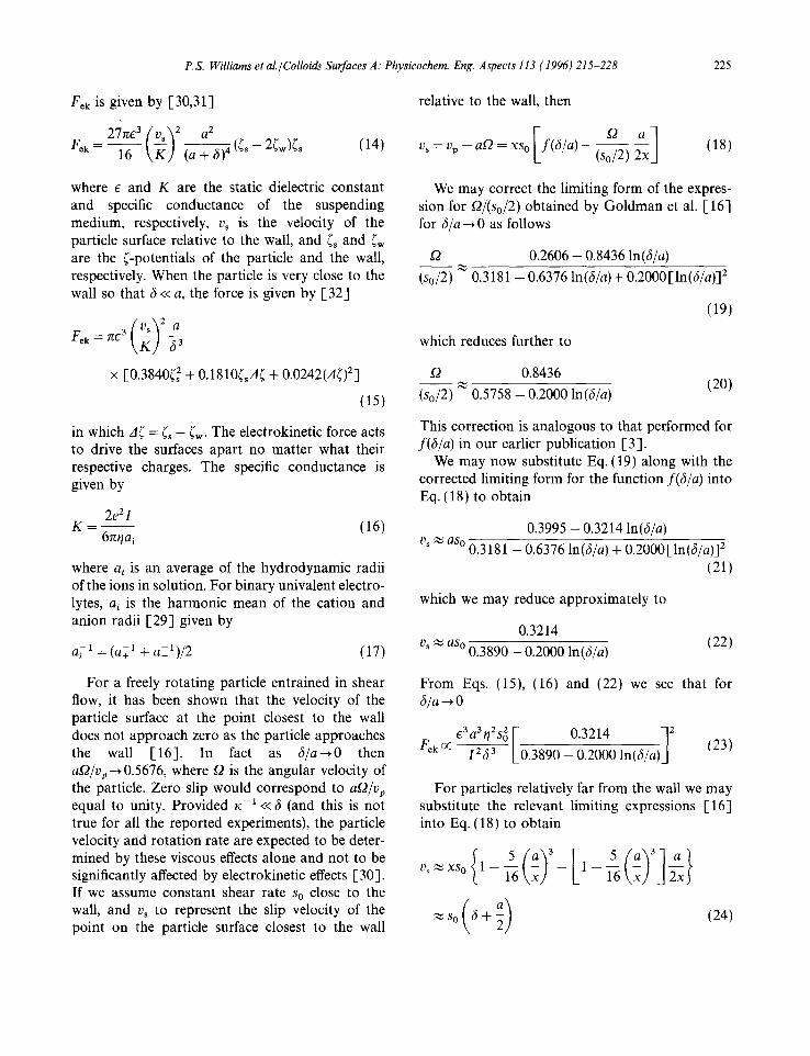
Fek is given by [30,31]
F~k-- 16 ~ (~ + 2ffw)~s (14)
relative to the wall, then
I - ° ' xl v~ = Vp -- at2 = xso f (b /a ) - (So/2) (18)
where e and K are the static dielectric constant and specific conductance of the suspending medium, respectively, vs is the velocity of the particle surface relative to the wall, and ~s and ~w are the ~-potentials of the particle and the wall, respectively. When the particle is very close to the wall so that b << a, the force is given by [32]
Fek = roe 3 b-- ~
× [0.3840( 2 + 0.1810(~A( + 0.0242(A() 2]
(15)
in which A( = (s -- (~. The electrokinetic force acts to drive the surfaces apart no matter what their respective charges. The specific conductance is given by
2e2I K - (16)
6rtr/ai
where ai is an average of the hydrodynamic radii of the ions in solution. For binary univalent electro- lytes, ai is the harmonic mean of the cation and anion radii [29] given by
a~ -1 = (a+ 1 --t- a7_1)/2 (17)
We may correct the limiting form of the expres- sion for t2/(So/2) obtained by Goldman et al. [ 16] for 6/a ~ 0 as follows
£2 0.2606 - 0.8436 ln(b/a)
(s0/2) 0.3181 - 0.6376 ln (b /a)+ 0.2000[ln(b/a)] 2
(19)
which reduces further to
t2 0.8436 (20)
(So/2) 0.5758-0.2000In(b/a)
This correction is analogous to that performed for f (b /a) in our earlier publication [3].
We may now substitute Eq. (19) along with the corrected limiting form for the function f (b /a ) into Eq. (18) to obtain
0.3995 - 0.3214 ln(b/a)
v~ ~ aso 0.3181 - 0.6376 ln(b/a) + 0.2000[ln(b/a)] 2
(21)
which we may reduce approximately to
0.3214 (22)
vs ~ aso 0.3890 - 0.2000 In(b/a)
For a freely rotating particle entrained in shear flow, it has been shown that the velocity of the particle surface at the point closest to the wall does not approach zero as the particle approaches the wall [16]. In fact as 6 / a ~ O then at2/vp ~ 0.5676, where t2 is the angular velocity of the particle. Zero slip would correspond to at2/Vp equal to unity. Provided K-x<< 6 (and this is not true for all the reported experiments), the particle velocity and rotation rate are expected to be deter- mined by these viscous effects alone and not to be significantly affected by electrokinetic effects [30]. If we assume constant shear rate So close to the wall, and vs to represent the slip velocity of the point on the particle surface closest to the wall
From Eqs. (15), (16) and (22) we see that for b/a --, 0
£3 a3 r/2S~ V 0.3214 12 Fek ~: ~ [_0.3890 -- 0.2000 ln(b/ai (23)
For particles relatively far from the wall we may substitute the relevant limiting expressions [16] into Eq. (18) to obtain
Vs~XS° (1 - -~ - -6 (a )3 - - [ 1 - 5 ( a - ) 3 ] k x J J 2xJ

226 P.S. Williams et al./Colloids Surfaces A: Physicochem. Eng. Aspects 113 (1996) 215-228
In this case, we obtain the following proportional- ity
E3a2y]2S2(6 + a /2) 2
Fek OC i2(a + 6) 4 (25)
For the conditions typical of steric FFF, we would expect the behavior to fall between those of Eqs. (23) and (25). The dependence of F~k on a 3 shown by Eq. (23) is consistent with our observa- tions for FLw. It is not possible to say if the dependence on 6 -3 is to be dismissed since the equation also includes an additional 6 dependence. The rapid increase of FCk with reduction in 6 would be moderated to a certain extent by the reduction in the final squared term. The dependence on q2 in both Eq. (23) and Eq. (25) may be reconciled with our observation of a higher-order dependence of FLw on ~/ at higher viscosities [5]. The latter work was carried out with ternary (water/ ethanol/glycerol) carrier mixtures which were of equal density but differed in viscosity. The ternary mixtures would be expected to exhibit lower e in comparison to water, which would moderate to some extent the effects of the increased viscosity. The dependence of F~k on the square of So is not generally in accordance with our observations of FLw, although such behavior was noted in relation to Figs. 4 and 5. While FLw is apparently slightly reduced by increasing I (although another explana- tion for this has been given), the dependence on the reciprocal of 12 is not borne out. While electro- kinetic lift forces may be significant under certain conditions, the relative insensitivity of measured FLw to ionic strength of the carrier solution consti- tutes strong evidence against an electrokinetic mechanism for near-wall lift force.
5. Conclusions
A mechanism for the experimentally measured near-wall contribution to hydrodynamic lift force has not yet been discovered. It does not, however, appear to have an electrokinetic origin. The possi- bility (unlikely as it is) may be advanced that FLw is simply an artifact corresponding to the observed particle elution behavior in some limited region of
for steric FFF, a region where various lift force contributions having different dependences on experimental parameters act in concert to give the overall apparent dependences seen for Few. Consider the particle size and shear rate depen- dences of the various proposed contributions to the lift force
Fr ~ al s 0 Fa oc al s 0 FLw OC a3 s~
Fek oc a 3 So 2 ELi z~ a4s g
The dependences for Few do fall between those for other contributions. However, theory predicts that as the ionic strength is raised, both Fr and Fek will be reduced to insignificance for typical values of the equilibrium 6 calculated via the solution of Eq. (6). Yet it is under these conditions that the fit to a model where F L is given by the sum of FLw and Fei is best. Such an explanation therefore appears unlikely.
Other possible explanations for the near-wall lift force require further investigation. The effects of surface roughness, which might disturb the flow properties for distances comparable to 6 away from the surface, should be examined. Also, any fundamental error in the velocity slip term (as given in Ref. [16]) would alter the force-versus-6 relationship since 6 is obtained on the basis of measured particle velocities or retention times [3].
The data presented in this work, amounting to 650 measurements of the elution time, appear to be consistent with a model in which the equilibrium particle height above the accumulation wall is determined by the following balance of forces
IFGI = Few + FLi + FoLvo (26)
where FLw remains an empirical contribution described by Eq. (3), Fei is the lift force due to fluid inertia effects (see Eqs. (1) and (2)), and FDevo is the net repulsive force due to double-layer interaction. For typical ionic strength carrier solu- tions, field strengths, and carrier flow rates, the latter contribution (FoLvo) tends to be negligible. It might be added that if experiments are to be designed to determine the origin of near-wall lift forces then the carrier solution should be of suffi- cient ionic strength to remove the complicating contribution due to double-layer interactions.

P.S. Williams et al./Colloids Surfaces A: Physicochem. Eng. Aspects 113 (1996) 215-228 227
Acknowledgment Greek letters
This work was CHE-9322472 from Foundation.
supported by grant the National Science
List of symbols
a
al
A132
b C
e
f(h/a) v~ Vok V~ FL ELi
VLw v~ g(x/w) G I k K Ltt r o
R
s O
T
v(x)
Vp
I) s
(v>
W
particle radius an average of hydrodynamic radii of ions in solution effective Hamaker constant for materials 1, and 2 interacting across medium 3 breadth of channel coefficient of the empirical near-wall lift force as given by Eq. (3) the unit electronic charge particle retardation factor van der Waals attractive force electrokinetic lift force sedimentation force lift force inertial lift force near-wall lift force repulsive electrostatic force function of x/w given by Eq. (2) field strength measured as acceleration ionic strength Boltzmann constant specific conductance tip-to-tip channel length radius of rotation of sedimentation channel retention ratio undisturbed shear rate at the wall temperature carrier velocity at distance x from accumu- lation wall particle velocity along length of channel velocity of particle surface at point closest to wall relative to wall mean carrier velocity volumetric carrier flow rate distance of particle center from the accu- mulation wall channel thickness
Ap
E
60
~s ~w
K
P
% (2)
(2
distance from particle surface to the wall, equal to x - a density difference between particle and the carrier fluid static dielectric constant permittivity of free space l-potential of particle (-potential of wall carrier viscosity reciprocal of double-layer thickness density of carrier fluid surface potential of particle surface potential of wall angular velocity of centrifuge angular velocity of particle
References
[ 1 ] J.C. Giddings, Science, 260 (1993) 1456-1465. 1,2] M. Martin and P.S. Williams, in F. Dondi and
G. Guiochon (Eds.), Theoretical Advancement in Chromatography and Related Separation Techniques, NATO ASI Ser. C: Mathematical and Physical Sciences, Vol. 383, Kluwer, Dordrecht, 1992, pp. 513 580.
1,3] P.S. Williams, T. Koch and J.C. Giddings, Chem. Eng. Commun., 111 (1992) 121-147.
1,4] P.S. Williams, S. Lee and J.C. Giddings, Chem. Eng. Commun., 130 (1994) 143-166.
I-5] P.S. Williams, M.H. Moon, Y. Xu and J.C. Giddings, Chem. Eng. Sci., in press.
[6] T. Koch and J.C. Giddings, Anal. Chem., 58 (1986) 994-997.
[7] J.C. Giddings, M.N. Myers, K.D. Caldwell and J.W. Pav, J. Chromatogr., 185 (1979) 261-271.
1,8] K.D. Caldwell, T.T. Nguyen, M.N. Myers and J.C. Giddings, Sep. Sci. Technol., 14 (1979) 935-946.
I-9] J.C. Giddings, M.H. Moon, P.S. Williams and M.N. Myers, Anal. Chem., 63 (1991) 1366-1372.
[10] P.S. Williams, M.H. Moon, and J.C. Giddings, in N.G. Stanley-Wood and R.W. Lines (Eds.), Particle Size Analysis, Royal Society of Chemistry, Cambridge, UK, 1992, pp. 280-289.
[11] R.G. Cox and H. Brenner, Chem. Eng. Sci., 23 (1968) 147-173.
1-12] B.P. Ho and L.G. Leal, J. Fluid Mech., 65 (1974) 365-400. [13] R.G. Cox and S.K. Hsu, Int. J. Multiphase Flow, 3
(1977) 201-222. [14] P. Vasseur and R.G. Cox, J. Fluid Mech., 78 (1976)
385-413. 1-15] P.S. Williams, Sep. Sci. Technol., 29 (1994) 11-45.

228 P.S. Williams et aL /Colloids Surfaces A." Physicochem. Eng. Aspects 113 (1996) 215-228
[16] A.J. Goldman, R.G. Cox and H. Brenner, Chem. Eng. Sci., 22 (1967) 653-660.
[17] M.E. Hansen and J.C. Giddings, Anal. Chem., 61 (1989) 811-819.
[18] Y. Mori, B. Scarlett and H.G. Mercus, J. Chromatogr., 515 (1990) 27-35.
[19] E. Dalas, P. Koutsoukos and G. Karaiskakis, Colloid Polym. Sci., 268 (1990) 155-162.
[20] E.J. Verwey and J.Th. Overbeek, Theory of Stability of Lyophobic Colloids, Elsevier, Amsterdam, 1948.
[21] D.J. Shaw, Introduction to Colloid and Surface Chemistry, 3rd edn., Butterworths, London, 1980, Chapter 7.
[22] J. Visser in E. Matijevi6 (Ed.), Surface and Colloid Science, Vol. 8, Wiley, New York, 1976, Chapter 1.
[23] J. Visser, J. Colloid Interface Sci., 55 (1976) 664-677. [24] J.N. Israelachvili, Intermolecular and Surface Forces, 2nd
edn., Academic Press, London, 1992, Chapter 11.
[25] H.V. Olphen and K.J. Mysels, Physical Chemistry: Enriching Topics from Colloid and Surface Science, Thorex, La Jolla, 1975, Chapter 1.
[26] Th.J.J. van den Hoven and B.H. Bijsterbosch, J. Colloid Interface Sci., 115 (1986) 559-560.
[27] D.C. Prieve and B.M. Alexander, Science, 231 (1986) 1269-1270.
[28] B.M. Alexander and D.C. Prieve, Langmuir, 3 (1987) 788-795.
[29] D.C. Prieve and S.G. Bike, Chem. Eng. Commun., 55 (1987) 149-164.
[30] S.G. Bike and D.C. Prieve, J. Colloid Interface Sci., 154 (1992) 87 96.
[31] T.G.M. van de Ven, P. Warszynski and S.S. Dukhin, J. Colloid Interface Sci., 157 (1993) 328-331.
f-32] S.G. Bike and D.C. Prieve, J. Colloid Interface Sci., 136 (1990) 95 112.