collie river valley tourist park accessible bathroom
TRANSCRIPT
Collie River Valley Tourist Park Accessible Bathroom 1 Porter Street, Collie, WA 6225, Tel: (08) 9734 5088
Tender and Specification for the Works Closing of tenders
Date: 14 June 2019
Time: 5pm
Place for lodgement
Tender Box
Shire of Collie Administration Centre
87 Throssell Street
COLLIE WA 6225
Or:
Electronic submission via email at:
Revision Date Approved by
Issue for Tender 23 May 2019 SG

NATSPEC Table of contents and wall fixtures
© NATSPEC (Apr 18) 1 Collie River Valley Accessible Bathroom
TABLE OF CONTENTS Table of contents ................................................................................................................................... 1
0121 Tendering ...................................................................................................................................... 2
0131 Preliminaries ................................................................................................................................. 8
0171 General requirements ................................................................................................................ 14
0180 Scope of Work ............................................................................................................................ 19
0184 Termite management ................................................................................................................. 20
0201 Demolition ................................................................................................................................... 21
0271 Pavement base and subbase .................................................................................................... 23
0310 Concrete ...................................................................................................................................... 25
0331 Brick and block construction .................................................................................................... 30
0382 Light timber framing ................................................................................................................... 35
0453 Doors ........................................................................................................................................... 39
0455 Door hardware and wall fixtures ............................................................................................... 42
0511 Lining ........................................................................................................................................... 44
0621 Waterproofing - wet areas ......................................................................................................... 46
0631 Ceramic tiling .............................................................................................................................. 49
0671 Painting ....................................................................................................................................... 53
0802 Hydraulic design and install ...................................................................................................... 57
0902 Electrical design and install ...................................................................................................... 62
Appendix 1 – existing site photos ..................................................................................................... 67
Appendix 2 – Door Hardware and wall fixtures schedule ..................... Error! Bookmark not defined.

NATSPEC 0121 Tendering and wall fixtures
© NATSPEC (Apr 18) 2 Collie River Valley Accessible Bathroom
0121 TENDERING
1 CONDITIONS OF TENDERING
1.1 RESPONSIBILITIES
General This tender is for the construction of a Accessible Bathroom in an existing laundry at the Collie River Valley Tourist Park.
1.2 GENERAL
Status General: These conditions of tendering will not form part of the contract.
Code of practice General: Tendering procedure will conform with AS 4120 1994 Code of Tendering
Definition General: In these conditions of tendering, the word principal has the same meaning as owner and proprietor.
1.3 PROJECT INFORMATION
Outline description of the works Construction of new bathroom and laundry facility
Description of the site Collie River Valley Tourist Park, 1 Porter Street COLLIE WA 6225 Tender documents The tender documents comprise the following:
- Conditions of tendering.
- General conditions of contract.
- Appendix or annexure to general conditions of contract, partly pre-completed.
- Specifications.
- Drawings.
1.4 FURTHER INFORMATION
Contact person Enquiries: Only refer enquiries to the following person at the Shire of Collie
Manager of Building Services - Mr Scott Geere
Tel: (08) 9734 9017
Email: [email protected]
Examination General: A full set of documents is available for examination, which may be arranged through the contact person. Site inspections and briefing No formal site inspection is arranged, Tenderers must visit the site during the tender period and determine all building requirements, traffic issues, storage, staging and logistics to complete the works. Tenderers shall also review the documents against the existing circumstances and should there be any discrepancies report those items to the architect a minimum of 5 days prior to the close of tenders and seek an instruction. By submission of a tender without notifying the architect of any discrepancies shall be acceptance of existing circumstances.
Site inspections must be arranged by appointment only via the Proprietor’s representative as detailed below:

NATSPEC 0121 Tendering and wall fixtures
© NATSPEC (Apr 18) 3 Collie River Valley Accessible Bathroom
Manager Shire Building Services - Mr Scott Geere
Addenda General: Written addenda issued by the principal are the only recognised explanations of, or amendments to, the tender documents.
1.5 PREPARATION OF TENDERS
Tender form Form: Submit the tender on the Tender form provided.
Addenda: Confirm on the Tender form that allowance has been made of each addendum and any extensions of the tender period.
Name and address of tenderer: State the following:
- If an individual, the name in full and address of the individual.
- If an unincorporated body, the registered business name and address of the body and the name in full and address of each member of the body.
- If a company, the name, ABN and registered office address of the company.
Address for service of notices: Include on the Tender form a street address for service of notices for the purpose of this tender and any subsequent contract arising out of this tender.
Execution: Sign the Tender form or, if a company, comply with the relevant provisions of the Corporations Law and regulations.
Scope Scope: Tender for the whole of the work described in the tender documents unless the tender documents provide otherwise.
Exclusions: If unable to tender on parts of the works, inform the contact person in writing as soon as possible, defining the relevant parts and giving reasons.
Completion General: Complete in full the Tender form and other required documents.
Alterations: Do not alter or add to tender documents except as may be required by these conditions of tendering.
Selected subcontracts General: Submit with the tender the identity of subcontractors proposed for selected subcontract work.
Alternatives General: Alternative proposals may be submitted with the tender for consideration, but:
- A conforming tender must be submitted, which complies with the tender documents.
- A detailed description of the alternative must be submitted, stating clearly the manner in which it differs from the requirements of the tender documents whilst complying with the principal’s commercial and technical objectives.
Alternative time for practical completion: Consideration will be given to alternative tenders which offer different times for practical completion. The prescribed liquidated damages will apply to those different times.
Alternative working hours and working days: If the tender includes an allowance for work at times other than the working hours or working days prescribed in the tender documents, submit the working hours and days proposed.
Evidence of contractor’s registration or licensing General: If it is a statutory requirement of the state or territory in which the works are located that a contractor (as defined by the statutory requirement) be registered or licensed to carry out the work described in the tender documents, submit with the tender evidence of registration or licence.
Program General: Submit a construction program in the form of a preliminary bar chart and network diagram, showing the following:
- Sequence of work.
- Periods within which various stages or parts of the work are to be executed.
NATSPEC 0121 Tendering and wall fixtures
© NATSPEC (Apr 18) 4 Collie River Valley Accessible Bathroom
- Critical paths of activities related to the work.
- Allowance for holidays.
- Restraints imposed by the contract documents.
- Significant milestones including separable parts, if any.
- Activity inter-relationships, including those activities to be undertaken by subcontractors and suppliers, both on and off site.
- External dependencies including provision of access, document approvals and work by others.
- The estimated value of work completed for each month.
Time for submission: Within 14 days of acceptance of Tender
Quality system Tenderer’s submission: Submit a statement of quality control resources.
Time for submission: Within 14 days of Acceptance of Tender
1.6 SUBMISSION OF TENDERS
Lodgement Procedure: Enclose tenders in a sealed envelope marked with the description of the work and tender item (if any) and lodge in the tender box at, or send by prepaid post to, the nominated place, by the date and time for closing of tenders.
Franking: Impressions of franking machines are not acceptable evidence of timely posting or dispatch.
Supporting information: Enclose in a separate sealed envelope marked with the description of the work and the identity of the tenderer.
Oral tenders: Oral tenders will not be considered.
Tenders submitted by Email shall NOT be accepted
Tenders submitted by Facsimile shall NOT be accepted
Late tenders Late tenders sent by any form of delivery or transmission will not be considered.
Closing of tenders Date: 14th June 2019
Time: 5pm
Place for lodgement
Tender Box
Shire of Collie Administration Centre
87 Throssell Street
COLLIE WA 6225
Or:
Electronic submission via email at:
1.7 PROCEDURES AFTER TENDER PERIOD
Tender validity period General: Unless withdrawn, tenders must remain valid from the date and time for closing of tenders, for the following period: Refer to Form of Tender
Public opening of tenders Not applicable

NATSPEC 0121 Tendering and wall fixtures
© NATSPEC (Apr 18) 5 Collie River Valley Accessible Bathroom
Evaluation of tenders Tenders shall be evaluated in accordance with the Compliance Criteria, Pricing Schedule and Qualitative Criteria
Correction of errors in tenders Procedure: All corrections to be advised by issuance of an Addenda to ALL tenderers
Additional information General: If required, submit additional information, by the stipulated date and time, to allow further consideration of the tender before any tender is accepted. Failure to meet this requirement may result in the tender being rejected.
Confidentiality General: Treat as confidential any information provided after the tender period.
Acceptance of tender Non-acceptance: The principal is not bound to accept the lowest or any tender, or to give reasons.
Acceptance: A tender is not accepted until notice in writing of acceptance is:
- Handed to the tenderer.
- Sent by prepaid post to, or left at, the address for service of notices stated in the Tender form.
- Transmitted by facsimile to the tenderer’s facsimile number.
Formal instrument of agreement: Required.
Arrangements for return of tender documents Return of documents: Not required
Period between acceptance of tender and possession of site Anticipated maximum period: Refer to Tender offer Form
NATSPEC 0121 Tendering and wall fixtures
© NATSPEC (Apr 18) 6 Collie River Valley Accessible Bathroom
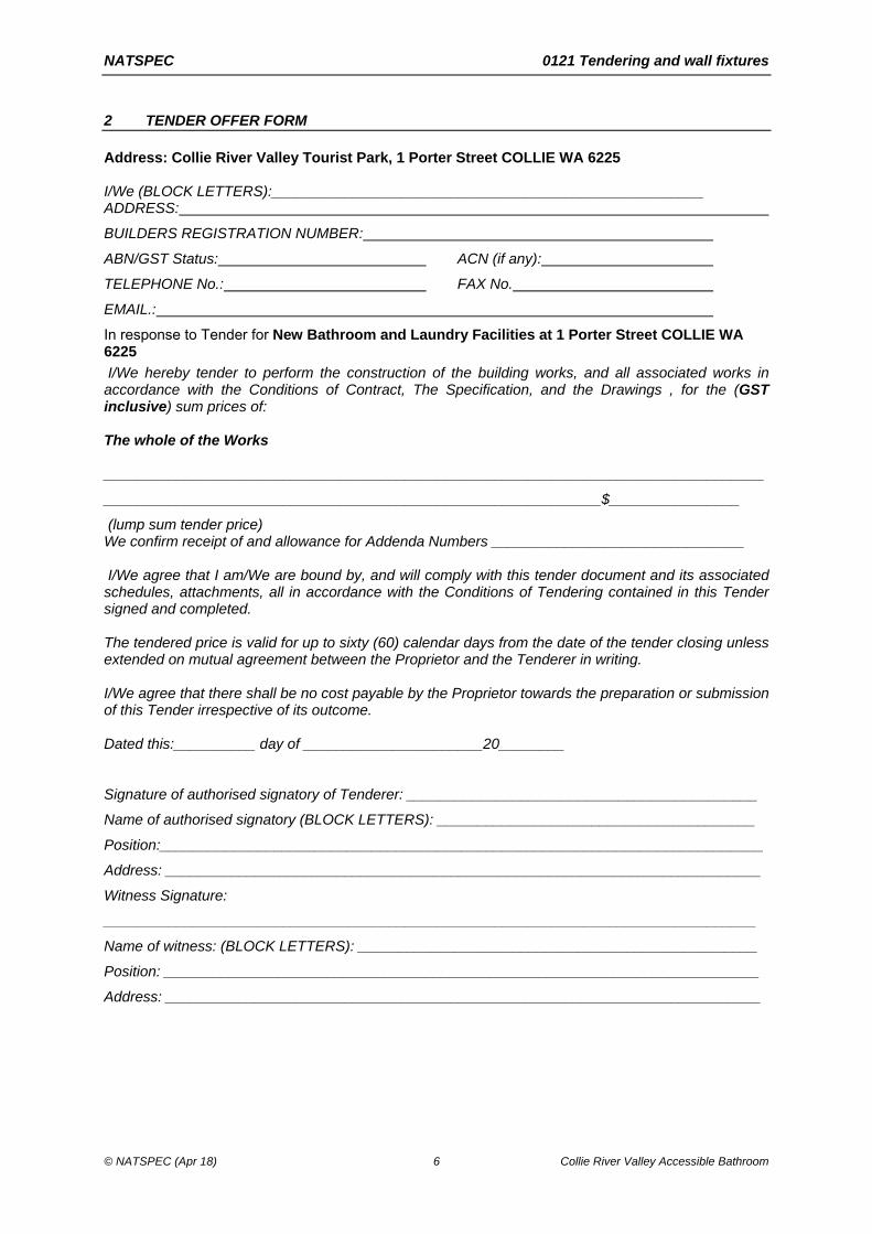
2 TENDER OFFER FORM
Address: Collie River Valley Tourist Park, 1 Porter Street COLLIE WA 6225 I/We (BLOCK LETTERS):_____________________________________________________ ADDRESS:
BUILDERS REGISTRATION NUMBER:
ABN/GST Status: ACN (if any):
TELEPHONE No.: FAX No.
EMAIL.:
In response to Tender for New Bathroom and Laundry Facilities at 1 Porter Street COLLIE WA 6225
I/We hereby tender to perform the construction of the building works, and all associated works in accordance with the Conditions of Contract, The Specification, and the Drawings , for the (GST inclusive) sum prices of: The whole of the Works _________________________________________________________________________________
_____________________________________________________________$________________
(lump sum tender price) We confirm receipt of and allowance for Addenda Numbers _______________________________ I/We agree that I am/We are bound by, and will comply with this tender document and its associated schedules, attachments, all in accordance with the Conditions of Tendering contained in this Tender signed and completed. The tendered price is valid for up to sixty (60) calendar days from the date of the tender closing unless extended on mutual agreement between the Proprietor and the Tenderer in writing. I/We agree that there shall be no cost payable by the Proprietor towards the preparation or submission of this Tender irrespective of its outcome. Dated this:__________ day of ______________________20________ Signature of authorised signatory of Tenderer: ___________________________________________
Name of authorised signatory (BLOCK LETTERS): _______________________________________
Position:__________________________________________________________________________
Address: _________________________________________________________________________
Witness Signature:
________________________________________________________________________________
Name of witness: (BLOCK LETTERS): _________________________________________________
Position: _________________________________________________________________________
Address: _________________________________________________________________________

NATSPEC 0121 Tendering and wall fixtures
© NATSPEC (Apr 18) 7 Collie River Valley Accessible Bathroom
PRICE 2 – WHOLE OF THE WORKS
TENDER SUM BREAKDOWN
Tenderer’s Name:
Date:
1. PRELIMINARIES $ EXCL.GST
2. $ EXCL.GST
3. $ EXCL.GST
4. $ EXCL.GST
5. $ EXCL.GST
6. $ EXCL.GST
7. $ EXCL.GST
8. $ EXCL.GST
9. $ EXCL.GST
10. $ EXCL.GST
11. $ EXCL.GST
12. $ EXCL.GST
13. $ EXCL.GST
14. $ EXCL.GST
SUBTOTAL
$
EXCL.GST
+ GST
$
TOTAL
$
INCL. GST
NATSPEC 0131 Preliminaries and wall fixtures
© NATSPEC (Apr 18) 8 Collie River Valley Accessible Bathroom
0131 PRELIMINARIES
1 GENERAL
1.1 GENERAL
General conditions General: To ABIC SW-2018 Simple Works Contract, issued by the Australian Institute of Architects and Master Builders Australia. Variables to this contract shall be as set out within the extracts of Schedules at the end of this Section
Interpretation Cross reference: The clause INTERPRETATION, in the General requirements worksection, also applies.
1.2 THE SITE
Site restrictions Site limitations: Comply with the restrictions on the use of the site.
Access: Comply with access on to and within the site, use of the site for temporary works and constructional plant, including working and storage areas, location of offices, workshops, sheds, roads and parking, as documented.
Occupied premises General: For the parts of the site documented in the Occupied premises schedule:
- Allow occupants to continue in secure possession and occupancy of the premises for the required period.
- Maintain safe access for occupants.
- Arrange work to minimise nuisance to occupants and for their safety.
- Protect occupants against weather, dust, dirt, water or other nuisance.
Proposals: Submit details of proposed methods.
- Purpose of submission: Information only.
Protection of persons and property Temporary works: Provide and maintain required barricades, guards, fencing, shoring, temporary roadways, footpaths, signs, lighting, watching and traffic management.
Accessways and services: Do not obstruct or damage roadways and footpaths, drains and watercourses and other existing services in use on or adjacent to the site. Determine the location of such services.
Property: Do not interfere with or damage trees and property which are to remain on or adjacent to the site, including adjoining property encroaching onto the site.
Rectification Accessways and services: Rectify immediately any obstruction or damage to roadways and footpaths, drains and watercourses and other existing services in use on or adjacent to the site. Provide temporary services whilst repairs are carried out.
Property: Rectify immediately any interference or damage to trees and property which are to remain on or adjacent to the site, including adjoining property encroaching onto the site.
Existing services Service to be continued: Repair, divert or relocate, as documented.
Trenches: If the existing service crosses the line of a required trench, or will lose support when the trench is excavated, provide permanent support for the existing service.
Redundant services: Remove redundant parts and make safe.
Interruptions to services: Minimise the number and duration of interruptions.
Proposals: Submit proposals for action to be taken to existing services before starting this work.
- Purpose of submission: For review.

NATSPEC 0131 Preliminaries and wall fixtures
© NATSPEC (Apr 18) 9 Collie River Valley Accessible Bathroom
Adjoining property Notice: At least 10 working days before commencing work, submit to owners and occupants of adjoining property written notice of intention to commence work and an outline description of the type and extent of work.
Revealed encroachments: If the works reveal unknown encroachments of adjoining property on to the site or of existing site structures on to adjoining property, immediately seek instructions.
Records: For each property described in the Adjoining properties to be recorded schedule:
- Inspect the property with the architect and owner and occupant of the property, before commencement of work.
- Make detailed records of conditions existing within the property, especially structural defects and other damage or defacement.
- Arrange for at least 2 copies of each record, including drawings, written descriptions, and photographs, endorsed by the owner and occupant of the property, or their representatives, as evidence of conditions existing before commencement of work.
Endorsed copies: Submit one endorsed copy of each record. Keep the other endorsed copy on site.
- Purpose of submission: Information only.
1.3 CONSTRUCTION PLANT
Access Access route: As nominated and documented.
Parking Owner’s existing parking areas: Use spaces only in designated parking areas.
Use of existing services General: Existing services may be used as temporary services for the performance of the contract subject to conditions of use, as documented in the Existing services schedule.
Temporary services General: Provide temporary services for the performance of the contract as documented in the Temporary services schedule.
Project signboards General: Provide project-specific signboards and as follows:
- Locate where directed.
- Maintain in good condition for duration of the work.
- Obtain permission for removal.
- Remove on completion.
1.4 BUILDING THE WORKS
Surveys General: Use information from a licensed surveyor for the following:
- Setting out.
- Check surveys.
- Final survey.
Survey marks Definition: A survey peg, bench mark, reference mark, signal, alignment, level mark or any other mark used or intended to be used for the purpose of setting out, checking or measuring the work.
Care of survey marks: Preserve and maintain the principal’s survey marks in their true positions.
Rectification: If the survey marks are disturbed or obliterated, immediately rectify.
Safety Accidents: Promptly notify the contract administrator of the occurrence of the following:
- Accidents involving death or personal injury.
- Accidents involving loss of time.
- Incidents with accident potential such as equipment failure, slides and cave-ins.
Accident reports: Submit reports of accidents.
- Purpose of submission: Information only and action as required.

NATSPEC 0131 Preliminaries and wall fixtures
© NATSPEC (Apr 18) 10 Collie River Valley Accessible Bathroom
Contractor's representative General: Must be accessible, and fluent in English and technical terminology.
Subcontracting General: Submit a complete list of proposed subcontractors and suppliers.
Items supplied by owner General: Materials and other items supplied free of charge to the contractor for installation in the execution of the works, as documented in the Items supplied by owner schedule. Unload and take delivery, inspect for defects and take care of the items. If defects are found, advise. Return unused items to the principal. Once delivered to site ensure all items are covered by insurance of the Works.
1.5 COMPLETION OF THE WORKS
Reinstatement General: Before the date for practical completion, clean and repair damage caused by installation or use of temporary work and restore existing facilities used during construction to original condition.
Adjoining property Evaluation: At practical completion, for each property described in the Adjoining properties to be recorded schedule inspect the property with the architect and owner and occupant of the property, recording any damage that has occurred since the pre-commencement inspection.
Pest eradication General: Employ suitably qualified pest exterminators. At practical completion, verify that completed works are free of pest types as documented in the Pest eradication treatments schedule.
1.6 MISCELLANEOUS
Contractor and owner to observe confidentiality Publicity: Do not issue information concerning the project for publication in the media without prior written approval of the owner.
Compliance with the law Requirements of authorities: The Principal, before entering into the contract, has given the notices, paid the fees, and obtained the permits, approvals and other authorisations, as documented in the Prior applications and approvals schedule.
2 SELECTIONS
2.1 SCHEDULES
Adjoining properties to be recorded schedule:
Title Adjoining property owner Description
Services schedule
Service Remarks
Power
Water
Sewer
Authority approvals schedule
Authority Document Conditions

NATSPEC 0131 Preliminaries and wall fixtures
© NATSPEC (Apr 18) 11 Collie River Valley Accessible Bathroom
Authority Document Conditions

NATSPEC 0131 Preliminaries and wall fixtures
© NATSPEC (Apr 18) 12 Collie River Valley Accessible Bathroom
Contract Schedules
With reference to ABIC SW– 2018 Simple Works Contract the following Schedules shall apply
Schedule 1
Item 7 Security Retention or Bank Guarantee
Item 8 Retention % Five (5)
Item 9 % of guarantee Five (5) in two guarantees of 2.5%
Item 10 Period for payment Fourteen (14)
Item 11 Public Liability Insurance by
The Contractor
Item 12 Contract works Insurance by
The Contractor
Item 13 % fees for consultants Twelve (12)
Item 14 % for Demolition Ten (10)
Item 15 Insurance for liability $5,000,000
Item 16 Insurance excess $500 payable by Contractor
Item 17 % for contractor Ten (10)
Item 18 Cost & stage of completion
N/A
Item 19 % of difference Nil (0)
Item 20 Delay for weather Thirty (30) days
Item 21 Adjustment of time costs Nil
Item 22 Date of completion Whole of the Works
Eight (8) weeks after date of possession
Item 23 Commissioning Tests All electrical, hydraulic & mechanical items
Item 24 Rate for liquidated damages
$100 per calendar day
Item 25 Liability period Twelve (12) months
Item 26 Date for progress claim Monthly – Date to be agreed
Item 27 Information for claim Trade break down of claim with total amount per trade, amount completed per trade and amount claimed.
Item 28 Interest amount Eight (8)
Item 29 Governing law Western Australia
Item 30 Official documents Building Permit
Schedule 2
Special Conditions: Not Applicable
Schedule 3
Order of Precedence: The Contract
The Specification
The Drawings

NATSPEC 0131 Preliminaries and wall fixtures
© NATSPEC (Apr 18) 13 Collie River Valley Accessible Bathroom
Schedule 4
Site Information: Refer Appendices
Schedule 5
Guarantee Format: N/A
Schedule 6
Provisional Sums: Sum allowed (excl.GST)
Description Allowance for
$ NIL
$
ITEMS ABOVE NOMINATED FOR SUPPLY ONLY, THE ALLOWANCE EXCLUDES DELIVERY – IN ADDITION, THE BUILDER SHALL ALLOW FOR PROFIT AND ATTENDANCE, ALL DELIVERY & INSTALLATION INCLUDING SCREEDS, ADHESIVES, GROUTS, FIXINGS, WIRING, PLUMBING, LAYING, TRIMS ETC.
ITEMS ABOVE NOMINATED FOR SUPPLY AND INSTALL, THE BUILDER SHALL ALLOW FOR PROFIT AND ATTENDANCE, ALL ASSOCIATED ELECTRICAL, HYDRAULIC AND BUILDERS WORK IN ADDITION TO THE PROVISIONAL SUM
Schedule 7
Prime Costs: Sum allowed (excl.GST)
Description Particular person
$ NIL
NOTE: THE ABOVE ALLOWANCES EXCLUDE DELIVERY AND INSTALLATION – IN ADDITION, THE BUILDER SHALL ALLOW FOR PROCURING, DELIVERY, PLACING AND COMMISSIONING OF ALL OF THE ABOVE ITEMS.
Schedule 8
Items supplied by Owner for incorporation in to works and installed by contractor.
Description: Not applicable
Items supplied & installed by Owner and no allowance has been included in contract price.
Description: Not applicable
NOTE: For all separate contractors the builder shall allow access and amenities, power, water, scaffold and rubbish disposal at an appropriate time.
NATSPEC 0171 General requirements and wall fixtures
© NATSPEC (Apr 18) 14 Collie River Valley Accessible Bathroom
0171 GENERAL REQUIREMENTS
1 GENERAL
1.1 APPLICABILITY
General Requirement: Conform to 0171 General requirements, as appropriate, in all worksections.
1.2 PERFORMANCE
Energy efficiency Energy efficiency approval commitments: To the performance requirements of BCA 2.6, the construction requirements of BCA 3.12 and the Building performance schedule.
Structural design actions Standard: To the AS/NZS 1170 series and AS 4055, as appropriate.
Importance level to AS/NZS 1170.0: Level 2.
1.3 STANDARDS
Current editions General: Use referenced Australian or other standards (including amendments), and the BCA including state and territory variations which are current three months before the date of the contract except where other editions or amendments are required by statutory authorities. Any local authority requirements take precedence.
1.4 INTERPRETATION
Abbreviations General: For the purposes of this specification the following abbreviations apply:
- BCA: National Construction Code series
Volume One: Building Code of Australia Class 2 to 9 Buildings and / or
Volume Two: Building Code of Australia Class 1 and Class 10 buildings.
Definitions General: For the purposes of this specification, the following definitions apply:
- Owner: Owner has the same meaning as client, principal or proprietor and is the party to whom the contractor is legally bound to construct the works.
- Contractor: Means the same as builder.
- Documented: Documented, as documented and similar terms mean contained in the contract documents.
- Metallic-coated: Steel coated with zinc or aluminium-zinc alloy via a continuous hot-dip process.
- Hot-dip galvanized: Zinc coated to AS/NZS 4680 after fabrication.
- Professional engineer: As defined by the BCA.
- Proprietary: Identifiable by naming manufacturer, supplier, installer, trade name, brand name, catalogue or reference number.
- Provide: Provide and similar expressions mean supply and install and include development of the design beyond that documented.
- Required: Means required by the contract documents, the local council or statutory authorities.
- Supply: Supply, furnish and similar expressions mean supply only.
1.5 BUSHFIRE PROTECTION
General Bushfire Attack Level (BAL) to AS 3959 and BCA 3.7.4: To the Building performance schedule.

NATSPEC 0171 General requirements and wall fixtures
© NATSPEC (Apr 18) 15 Collie River Valley Accessible Bathroom
2 PRODUCTS
2.1 GENERAL
Manufacturers’ or suppliers’ recommendations General: Provide and select, if no selection is given, transport, deliver, store, handle, protect, finish, adjust and prepare for use the manufactured items in accordance with the current written recommendations and instructions of the manufacturer or supplier.
Proprietary items/systems/assemblies: Assemble, install or fix to substrate in accordance with the current written recommendations and instructions of the manufacturer or supplier.
Product identification Sealed containers: If materials or products are supplied by the manufacturer in closed or sealed containers or packages, bring the material or products to point of use in the original containers or packages.
Substitution Identified proprietary items: Identification of a proprietary item does not necessarily imply exclusive preference for the identified item, but indicates the necessary properties of the item.
Alternatives: If alternatives to the documented products, methods or systems are proposed, submit sufficient information to permit evaluation of the proposed alternatives for approval. Approval for alternatives shall not be assumed or relied upon and shall be at the sole discretion of the Owner or their Agent.
2.2 TIMBER
Moisture content General: Make milled products from timbers seasoned as follows:
- To within 3% of the equilibrium moisture content appropriate to the timber and its intended conditions of use.
- With no more than 3% difference between any 2 pieces in any one group.
Acclimatisation General: Acclimatise timber fitouts by stacking them for two weeks in the in-service conditions with air circulation to all surfaces after the following are complete:
- Air conditioning operational.
- Lighting operational.
- Site drainage and stormwater works are complete.
- Space fully enclosed and secure.
- Wet work complete and dry.
Unseasoned timber General: If unseasoned timber is provided, or variation in moisture content is likely, make allowance for shrinkage, swelling and differential movement.
Recycled timber Grit blasted or re-machined: Remove all nails and screws.
Classification: Visually graded.
Durability General: Provide timbers with natural durability appropriate to the conditions of use or preservative-treated timbers of equivalent durability.
Natural durability class of heartwood: To AS 5604.
Preservative treatment: To the AS 1604 series.
Minimum requirement: To the Natural and treated timber durability table.
Natural and treated timber durability table
Exposure Natural timber Treated timber Remarks
Required durability class to AS 5604
Required hazard class to the AS 1604 series
Inside, above ground. Completely protected
Class 4 H1 Treated timber resistant to lyctids. Untreated

NATSPEC 0171 General requirements and wall fixtures
© NATSPEC (Apr 18) 16 Collie River Valley Accessible Bathroom
Exposure Natural timber Treated timber Remarks
from the weather. Well ventilated
timber must be protected from termites
Inside, above ground. Protected from wetting with nil leaching. Well ventilated
Class 3 H2 Treated timber resistant to borers and termites. Untreated timber must be protected with a finish
Above ground, exposed to weather. Periodic moderate wetting and leaching
Class 2 H3 Treated timber resistant to borers, termites and moderate decay. Applicable to weatherboards, fascias, pergolas (above ground), window joinery, framing and decking
In-ground Class 1 H4 (Severe wetting and leaching)
Treated timber resistant to borers, termites and severe decay. Applicable to fence posts, greenhouses, pergolas (in-ground) and landscaping timbers
H5 (Extreme wetting and leaching and/or critical uses)
Applicable to retaining walls, piling, house stumps, building poles, cooling tower fill
2.3 STEEL
Durability General: Provide steel products protected from corrosion to suit the conditions of use.
Internal engineer designed steel members: Remove mill scale, rust, moisture and oil. Coat with a zinc phosphate primer to the manufacturer’s instructions.
Built-in products below damp-proof course: Stainless steel 316 or engineered polymer.
Corrosion resistance General: Conform to the atmospheric corrosivity category as defined in AS 4312, the AS/NZS 2312 series and the Building performance schedule.
Compliance: Conform to the Corrosion resistance table or provide proprietary products with metallic and/or organic coatings of equivalent corrosion resistance.
Corrosion resistance table
Atmospheric corrosivity category to AS 4312
Heavy steel members including lintels more than 3.2 mm thick
Steel cladding, lining, trims and flashings
C1 and C2 (Low) Galvanize after fabrication 600 g/m2
Metallic-coated sheet AZ150
C3 (Medium) Galvanize after fabrication 600 g/m2
Metallic-coated sheet AZ200
C4 and T (High) Stainless steel 316 or 316L or galvanize after fabrication 600 g/m2 plus organic coating
Metallic-coated sheet AZ200 plus organic coating
Preparation and pre-treatment Standard: To the AS 1627 series.
NATSPEC 0171 General requirements and wall fixtures
© NATSPEC (Apr 18) 17 Collie River Valley Accessible Bathroom
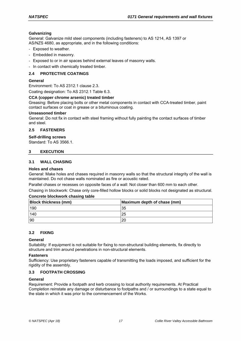
Galvanizing General: Galvanize mild steel components (including fasteners) to AS 1214, AS 1397 or AS/NZS 4680, as appropriate, and in the following conditions:
- Exposed to weather.
- Embedded in masonry.
- Exposed to or in air spaces behind external leaves of masonry walls.
- In contact with chemically treated timber.
2.4 PROTECTIVE COATINGS
General Environment: To AS 2312.1 clause 2.3.
Coating designation: To AS 2312.1 Table 6.3.
CCA (copper chrome arsenic) treated timber Greasing: Before placing bolts or other metal components in contact with CCA-treated timber, paint contact surfaces or coat in grease or a bituminous coating.
Unseasoned timber General: Do not fix in contact with steel framing without fully painting the contact surfaces of timber and steel.
2.5 FASTENERS
Self-drilling screws Standard: To AS 3566.1.
3 EXECUTION
3.1 WALL CHASING
Holes and chases General: Make holes and chases required in masonry walls so that the structural integrity of the wall is maintained. Do not chase walls nominated as fire or acoustic rated.
Parallel chases or recesses on opposite faces of a wall: Not closer than 600 mm to each other.
Chasing in blockwork: Chase only core-filled hollow blocks or solid blocks not designated as structural.
Concrete blockwork chasing table
Block thickness (mm) Maximum depth of chase (mm)
190 35
140 25
90 20
3.2 FIXING
General Suitability: If equipment is not suitable for fixing to non-structural building elements, fix directly to structure and trim around penetrations in non-structural elements.
Fasteners Sufficiency: Use proprietary fasteners capable of transmitting the loads imposed, and sufficient for the rigidity of the assembly.
3.3 FOOTPATH CROSSING
General Requirement: Provide a footpath and kerb crossing to local authority requirements. At Practical Completion reinstate any damage or disturbance to footpaths and / or surroundings to a state equal to the state in which it was prior to the commencement of the Works.
NATSPEC 0171 General requirements and wall fixtures
© NATSPEC (Apr 18) 18 Collie River Valley Accessible Bathroom
3.4 COMPLETION
General Removal of temporary work, services and plant: Remove temporary work services and construction plant within 10 working days after occupation of the works.
Final cleaning: Remove rubbish and surplus material from the site and clean the works throughout including interior and exterior surfaces exposed to view. Vacuum clean carpeted and soft surfaces. Clean debris from the site, roofs, gutters, downpipes and drainage systems.
Samples: Remove non-incorporated samples, sample panels and prototypes.
Warranties: Register with manufacturers, as necessary, and provide copies of manufacturers’ warranties.
Instruction manuals: Provide the manufacturers’ instruction manuals.
Operation: Make sure moving parts operate safely and smoothly.
Surveyor’s certificate: Provide a certificate which confirms that the work, including boundary fences, has been correctly located.
Services layout: Provide a plan which shows the location of underground services.
Authorities’ approvals: Provide evidence of approval of the local authority or principal accredited certifier and statutory authorities whose requirements apply to the work.
Keys: Provide two keys for each set of locks keyed alike and two keys for each lock keyed to differ.

0180 SCOPE OF WORK
The project is defined but is not limited to the following:
1. Demarcate and fence off work area. 2. Decommission affected services. 3. Remove existing fittings, wall tiles, floor tiles. Refer documentation. 4. Remove fire extinguisher and reinstall in laundry. 5. Remove portion of slab/ screed required for installation of new floor drains positions and to
achieve falls. 6. Construct brick bund walls (2 courses) below all new framed walls. 7. Remove brickwork to suit new doors. Install new doors with aluminium door relief vents and
kickplates both sides. Render and paint reveals and make good. 8. Screed slab to floor drains. Refer documentation. 9. Construct stud frame walls. Refer documentation. 10. Decommission and remove GPO adjacent to existing slop hopper. 11. Separate lighting to two circuits for UAT and laundry. 12. Supply and install new mechanical extraction in existing window to BCA requirements and
switch with lighting. Provide for necessary electrical components to allow fan (and light if necessary) to run on for 10 minutes.
13. Supply and install new drain and grate at door thresholds. 14. Construct new concrete entrance walkways on DMP with landing level with internal FFL. 15. On Eastern end, remove 5 concrete pavers of path that meets perpendicular to the walkway.
Raise lawn to level of new concrete walkway. Reinstate pavers to new concrete landing level. 16. Tile floor and walls. Refer documentation. 17. Supply and install sanitaryware and fittings. Refer documentation. 18. Paint rendered portions of existing walls internally and untiled portions of new stud framed
walls. 19. Recommission services. 20. Remove all debris and clean site before handover.
Refer below specifications for further detail.

0184 TERMITE MANAGEMENT
1 GENERAL
1.1 STANDARDS
General Standard: To AS 3660.1.
Chemical soil barriers – reticulation systems Type testing: To AS 3660.3 Section 5.
Termite management system notice Requirement: Permanently fix a durable notice in a prominent location to BCA 3.1.3.4.
Certification Requirement: Submit installation certificate to AS 3660.1 Appendix A3.
2 SELECTIONS
2.1 SCHEDULES
Termite management system schedule
Item Description
Termite control The whole building shall be protected in accordance with the requirements of the Australian standard AS3660:2014, termite management, part 1 new building work (2014 edition of AS3660.1)
All critical areas of termite entry including the external building perimeter, construction joints and slab penetrations shall be protected by a chemical termite management system that meets the requirements of the building code of Australia (BCA), installed in conjunction with a concrete slab built to AS2870.
The system must contain Bifenthrin at a concentration as per manufacturers recommendations and must be compliant with the relevant Australian Standards. The system installation is to conform with the manufacturer's installation guidelines and the installer shall provide a certificate of compliance with the BCA.
A minimum manufacturer's warranty of 50 years for the building shall be provided against termite breach.
The installer shall fix a durable notice within the building's meter box as per BCA requirements to state:
· details of installer and contact details · method of termite protection including all chemicals used · date of installation · life expectancy of system · recommended frequency of future inspections

NATSPEC 0201 Demolition and wall fixtures
© NATSPEC (Apr 18) 21 Collie River Valley Accessible Bathroom
0201 DEMOLITION
1 GENERAL
1.1 STANDARDS
Demolition Standard: To AS 2601.
1.2 SUBMISSIONS
Records Dilapidation record:
- Before demolition: Submit to each owner of each adjacent property a copy of the part of the record relating to that property and obtain their written agreement to the contents of the record.
- Rectification work: Submit written acceptance of rectification works from the owner of each adjoining property affected.
2 PRODUCTS
2.1 DEMOLISHED MATERIALS
General Removal: Except for items to be recovered for re-use in the works, or delivery to the owner and materials to be recycled in the works, take possession of demolished materials and remove them from the site. Do not burn or bury demolished materials on the site. Prevent spillage of demolished materials in transit.
Recycling: If possible, dismantle building components for off-site recycling.
3 EXECUTION
3.1 SUPPORT
Temporary support Existing buildings: Until permanent support is provided, provide temporary support for sections of existing buildings which are to be altered and which rely for support on work to be demolished.
3.2 PROTECTION
Encroachment General: Prevent the encroachment of demolished materials onto adjoining property, including public places.
Weather protection General: If walls or roofs are opened for alterations and additions, or the surfaces of adjoining buildings are exposed, provide temporary covers to prevent water penetration. Provide covers to protect existing plant equipment and materials intended for re-use.
Security General: If walls or roofs are opened for alterations or additions, provide security against unauthorised entry to the building.
Fixed items Individual protection: Protect items in their existing position and as documented in the Protection schedule.
3.3 DEMOLITION
Hazardous materials removal Standard: To AS 2601 clause 1.6.2.
Refer Hazardous Materials Schedule

NATSPEC 0201 Demolition and wall fixtures
© NATSPEC (Apr 18) 22 Collie River Valley Accessible Bathroom
Notice of completion General: Give at least 5 working days' notice of completion of demolition so that adjacent structures may be inspected following completion of demolition.
Reinstatement Assessment of damage: Use the dilapidation record to assess the damage and rectification work arising from the demolition work.
Rectification: Repair damage arising out of demolition work. Obtain written acceptance from the owner of each adjoining property of the completeness and standard of the rectification work.
4 SELECTIONS
4.1 SCHEDULES
Demolition to include items as shown on the drawings.

NATSPEC 0271 Pavement base and subbase and wall fixtures
© NATSPEC (Apr 18) 23 Collie River Valley Accessible Bathroom
0271 PAVEMENT BASE AND SUBBASE
1 PRODUCTS
1.1 BASE AND SUBBASE MATERIAL
Granular material Requirement: Provide unbound granular materials, including blends of two or more different materials which when compacted develop structural stability and are uniform in grading and physical characteristics.
Crushed rock Requirement: Provide crushed rock as follows:
- Base: 20 mm nominal.
- Subbase: 40 mm nominal.
Natural gravel Requirement: Provide unbound natural gravel materials as follows:
- Base: 20 mm nominal.
- Subbase: 40 mm nominal.
Base and subbase material properties and test methods Particle size distribution or grading: To AS 1289.3.6.1.
CBR (98% modified compaction): To AS 1289.6.1.1.
Unconfined compressive strength to AS 5101.4: Maximum 1.0 MPa.
2 EXECUTION
2.1 SUBGRADE PREPARATION
General Requirement: Prepare the subgrade in conformance with 0222 Earthwork.
2.2 PLACING BASE AND SUBBASE
General Weak surfaces: Do not place material on a surface that is weakened by moisture and is unable to support, without damage, the construction plant required to perform the works.
Spreading: Spread material in uniform layers without segregation.
Moisture content: Maintain wet mixed materials at the required moisture content before and during spreading. Add water to dry mixed materials through fine sprays to the entire surface of the layer after spreading, to bring the material to the required moisture content.
Compacted layer thickness: 200 mm maximum and 100 mm minimum. Provide layers of equal thickness in multilayer courses.
2.3 TOLERANCES
Surface level General: Provide a finished surface level which is free draining and evenly graded between level points.
2.4 BASE AND SUBBASE COMPACTION
General Construction operation: Compact each layer of fill to the required depth and density, as a systematic construction operation.
Minimum relative compaction table
Item description Minimum dry density ratio (modified compaction) to AS 1289.5.2.1
Subbase 95%

NATSPEC 0271 Pavement base and subbase and wall fixtures
© NATSPEC (Apr 18) 24 Collie River Valley Accessible Bathroom
Item description Minimum dry density ratio (modified compaction) to AS 1289.5.2.1
Base 98%
Compaction requirements General: Apply uniform compactive effort, over the whole area to be compacted, until the required density is achieved or until failure is acknowledged.
Equipment: Use rollers appropriate to the materials and compaction requirements documented.
NATSPEC 0310 Concrete and wall fixtures
© NATSPEC (Apr 18) 25 Collie River Valley Accessible Bathroom
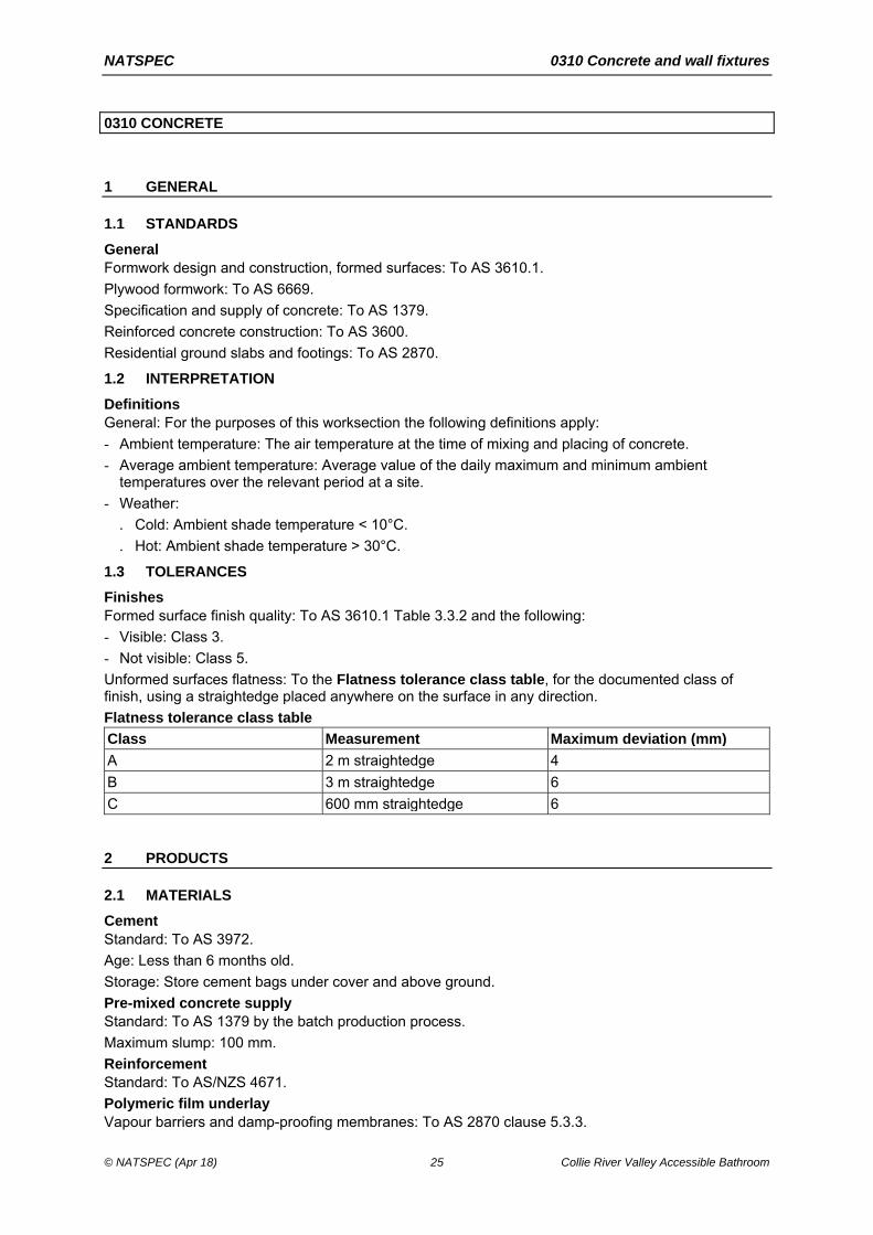
0310 CONCRETE
1 GENERAL
1.1 STANDARDS
General Formwork design and construction, formed surfaces: To AS 3610.1.
Plywood formwork: To AS 6669.
Specification and supply of concrete: To AS 1379.
Reinforced concrete construction: To AS 3600.
Residential ground slabs and footings: To AS 2870.
1.2 INTERPRETATION
Definitions General: For the purposes of this worksection the following definitions apply:
- Ambient temperature: The air temperature at the time of mixing and placing of concrete.
- Average ambient temperature: Average value of the daily maximum and minimum ambient temperatures over the relevant period at a site.
- Weather:
. Cold: Ambient shade temperature < 10°C.
. Hot: Ambient shade temperature > 30°C.
1.3 TOLERANCES
Finishes Formed surface finish quality: To AS 3610.1 Table 3.3.2 and the following:
- Visible: Class 3.
- Not visible: Class 5.
Unformed surfaces flatness: To the Flatness tolerance class table, for the documented class of finish, using a straightedge placed anywhere on the surface in any direction.
Flatness tolerance class table
Class Measurement Maximum deviation (mm)
A 2 m straightedge 4
B 3 m straightedge 6
C 600 mm straightedge 6
2 PRODUCTS
2.1 MATERIALS
Cement Standard: To AS 3972.
Age: Less than 6 months old.
Storage: Store cement bags under cover and above ground.
Pre-mixed concrete supply Standard: To AS 1379 by the batch production process.
Maximum slump: 100 mm.
Reinforcement Standard: To AS/NZS 4671.
Polymeric film underlay Vapour barriers and damp-proofing membranes: To AS 2870 clause 5.3.3.
NATSPEC 0310 Concrete and wall fixtures
© NATSPEC (Apr 18) 26 Collie River Valley Accessible Bathroom
Minimum thickness: 0.2 mm.
Curing compounds Standard: To AS 3799.
2.2 FORMWORK
General Lost formwork: Free of timber or chlorides and not to impair the structural performance of the concrete members.
Design Formwork: The design of the formwork is the contractor’s responsibility.
Plywood formwork Material: To AS 6669.
Grade: Use appropriate grade for the documented design dimensions, loading and surface quality.
Joints: Seal the joints consistent with the documented surface finish class.
Tolerances: To AS 3610.1 Section 3.
3 EXECUTION
3.1 POLYMERIC FILM UNDERLAY
Location General: Under slabs on ground including integral ground beams and footings, provide a vapour barrier or, in areas prone to rising damp or salt attack, a damp-proofing membrane.
3.2 FORMWORK
Preparation Cleaning: Before placing concrete, remove free water, dust, debris and stains from the formwork and the formed space.
Corners Work above ground: Chamfer at re-entrant angles, and fillet at corners.
- Face of bevel: 25 mm.
Void formers Protection: Keep void formers dry until time of use. Place them on a firm level surface and place reinforcement and concrete with minimum delay.
3.3 REINFORCEMENT
Supports Proprietary concrete, metal or plastic supports: To AS/NZS 2425 and as follows:
- Able to withstand construction and traffic loads.
- With a protective coating if they are ferrous metal, located within the concrete cover zone, or are used with galvanized or zinc-coated reinforcement.
Spacing:
- Bars: ≤ 60 diameters.
- Mesh: ≤ 600 mm.
Supports over membranes: Prevent damage to waterproofing membranes or vapour barriers. If appropriate, place a metal or plastic plate under each support.
Projecting reinforcement Protection: If starter or other bars extend beyond reinforcement mats or cages, through formwork or from cast concrete, provide a plastic protective cap to each bar until it is cast into later work.
Tying Requirement: Secure the reinforcement against displacement at intersections with either wire ties, or clips. Bend the ends of wire ties away from nearby faces of formwork or unformed faces to prevent the ties projecting into the concrete cover.
Bar lapping Requirement: Minimum lap as follows:
NATSPEC 0310 Concrete and wall fixtures
© NATSPEC (Apr 18) 27 Collie River Valley Accessible Bathroom
- Mesh sheets: Overlap by a minimum of 2 cross bars.
- Trench mesh: 500 mm.
- Bars: Greater of either 500 mm or 25 x bar diameter.
- Strip footing intersections and corners: Full width of intersecting reinforcement.
3.4 CONCRETE
Placing Method: Avoid segregation and loss of concrete, and minimise plastic settlement. Maintain a nominally vertical and plastic concrete edge during placement.
Horizontal elements: Place concrete in layers not more than 300 mm thick. Compact the following layer into previous layer before previous layer has taken initial set.
Compaction Methods: Use immersion and screed vibrators accompanied by hand methods as appropriate to remove entrapped air and to fully compact the mix.
Vibrators: Do not allow vibrators to contact set concrete, reinforcement or items including pipes and conduits embedded in concrete. Do not use vibrators to move concrete along the formwork. Avoid causing segregation by over-vibration.
Rain Protection: During placement and before setting, protect the surface from damage.
Placing in cold weather Temperature limits: Maintain the following:
- Freshly mixed concrete: ≥ 5°C.
- Formwork and reinforcement before and during placing: ≥ 5°C.
- Water: Maximum 60°C when placed in mixer.
Temperature control: Heat the concrete materials, other than cement, to the minimum temperature necessary so that the temperature of the placed concrete is ≥ 5°C.
Placing in hot weather Temperature limits: Maintain the following:
- Freshly mixed concrete at ≤ 35°C.
- Formwork and reinforcement before and during placing: ≤ 35°C.
Temperature control: Select one or more of the following methods of maintaining the temperature of the placed concrete at 35°C or less:
- Cover the horizontal transport containers.
- Spray the coarse aggregate using cold water prior to mixing.
- Use chilled mixing water or ice.
Evaporation control barriers: Erect barriers to protect freshly placed concrete from drying winds.
3.5 CURING
General Requirements: Taking into account the average ambient temperature at site over the relevant period affecting the curing, adopt procedures to make sure of the following:
- Curing: Cure continuously from completion of finishing, when the concrete has set sufficiently not to be damaged by the curing process, until the minimum total cumulative number of days or fractions of days, during which the air temperature in contact with the concrete is above 10°C, conforms to the following:
. Fully enclosed internal surfaces: 3 days.
. Other concrete surfaces: 7 days.
- End of curing period: Prevent rapid drying out at the end of the curing period.
Curing compounds Application: Provide a uniform continuous flexible coating without visible breaks or pinholes, which remains unbroken for at least the required curing period after application.
Substrates: Do not use wax-based or chlorinated rubber-based curing compounds on surfaces forming substrates to applied finishes, concrete toppings and cement-based render.
NATSPEC 0310 Concrete and wall fixtures
© NATSPEC (Apr 18) 28 Collie River Valley Accessible Bathroom
Cold weather curing Temperature: Maintain concrete surface temperature above 5°C for the duration of the curing period.
Hot weather curing Requirement: If the concrete temperature exceeds 25°C, or the ambient shade temperature exceeds 30°c, protect from drying winds and sun by using an evaporative retarder until curing is commenced.
Water curing Method: Select a method of ponding or continuously sprinkling water to prevent damage to the concrete surface during the required curing period.
3.6 JOINTS
Construction joints Location: Do not relocate or eliminate construction joints, or form undocumented construction joints. If emergency construction joints are made necessary by unforeseen interruptions to the concrete pour, submit a report on the action taken.
Preparation: Roughen and clean the hardened concrete joint surface. Remove loose or soft material, free water, foreign matter and laitance. Dampen the surface just before placing the fresh concrete and coat with a neat cement slurry.
Slip joints Requirement: If concrete slabs are supported on masonry, provide proprietary slip joints.
3.7 FORMED SURFACES
General Damage: Do not damage concrete works through premature removal of formwork.
Curing General: If formwork is stripped before the minimum curing period for the concrete has elapsed, continue curing the exposed faces as soon as the stripping is completed.
Surface repairs Method: If surface repairs are required, submit proposals.
3.8 UNFORMED SURFACES
Surface finishes General: As documented in the Unformed surface finishes schedule.
Surface repairs Method: If surface repairs are required, submit proposals.
3.9 COMPLETION
Formwork removal Extent: Remove formwork, other than lost formwork, including formwork in concealed locations.
Timing: Do not disturb formwork until concrete is hardened enough to withstand formwork movements and removal without damage.
Stripping times: Leave formwork for suspended structures in place after pouring concrete for the following periods:
- Vertical surfaces: To AS 3610.1 Appendix B Table B1.
- Horizontal surfaces: To AS 3600 clause 17.6.2.
Curing General: If formwork is stripped before the minimum curing period for the concrete has elapsed, continue curing the exposed faces as soon as the stripping is completed.
Protection General: Protect the concrete from damage due to construction loads, physical and thermal shocks and excessive vibrations, particularly during the curing period.
Surface protection: Protect finished concrete surfaces and applied finishes from damage.

NATSPEC 0310 Concrete and wall fixtures
© NATSPEC (Apr 18) 29 Collie River Valley Accessible Bathroom
4 SELECTIONS
4.1 SCHEDULES
Refer to the Architectural Drawings for extent of concrete work.

NATSPEC 0331 Brick and block construction and wall fixtures
© NATSPEC (Apr 18) 30 Collie River Valley Accessible Bathroom
0331 BRICK AND BLOCK CONSTRUCTION
1 GENERAL
1.1 STANDARD
General Materials and construction: To AS 4773.1 and AS 4773.2.
2 PRODUCTS
2.1 DURABILITY
General Exposure environment: To AS 4773.1 clause 4.3.
Exposure locations: To AS 4773.1 clause 4.4.
2.2 MATERIALS
Bricks and blocks Standard: To AS/NZS 4455.1 and AS/NZS 4455.3.
Minimum age of clay bricks: 7 days.
Salt attack resistance grade: To AS 4773.2 Table 2.1.
Mortar materials Sand: Fine aggregate with a low clay content and free from efflorescing salts, selected for colour and grading.
Mortar mixes: To AS 4773.1 Table 3.1.
Grout Standard: To AS 4773.1 clause 3.3.
2.3 BUILT-IN COMPONENTS
General Durability class of built-in components: To AS 4773.1 Table 4.1.
Steel lintels Angles and flats: Sizes to AS 4773.1 Table 12.2.
Cold-formed lintels: Designed to AS/NZS 4600.
Corrosion protection: To AS/NZS 2699.3.
Galvanizing: Do not cut after galvanizing.
Reinforcement Standard: To AS/NZS 4671.
Wall ties Standard: To AS/NZS 2699.1.
Type: A.
Corrosion protection: To AS/NZS 2699.1.
Connectors and accessories Standard: To AS/NZS 2699.2.
Corrosion protection: To AS/NZS 2699.2.
Flashings and damp-proof courses Standard: To AS/NZS 2904.

NATSPEC 0331 Brick and block construction and wall fixtures
© NATSPEC (Apr 18) 31 Collie River Valley Accessible Bathroom
3 EXECUTION
3.1 GENERAL
Mortar mixing General: Measure volumes accurately to the documented proportions. Machine mix for at least six minutes.
Protection Masonry materials and components: Protect from ground moisture and contamination.
During construction: Cover top surface of brickwork and blockwork to prevent the entry of rainwater and contaminants.
Bond Type: Stretcher bond.
Building in Embedded items: Build in wall ties and accessories as the construction proceeds. If not practicable to obtain the required embedment within the mortar joint in hollow masonry units, fill appropriate cores with grout or mortar.
Clearance for timber frame shrinkage General: In timber frame brick veneer construction, leave clearances between window frames and brick sill and between roof frames and the brick veneer as follows:
- Single storey frames and ground floor windows (not for slab on ground): 10 mm.
- Two storey frames and upper floor windows: 20 mm.
- Additional clearance: Accommodate additional shrinkage of unseasoned floor timbers.
Joining to existing General: Provide a control joint where joining to existing structures. Do not tooth new masonry into existing work unless approved by a professional engineer.
Mortar joints General: Set out masonry with joints of uniform width and the minimum of cutting of masonry units.
Solid and cored units: Lay on a full bed of mortar. Fill perpends solid. Cut mortar flush.
Face-shell bedded hollow units: Fill perpends solid. Cut mortar flush.
Joint thickness: 10 mm.
Finish: Conform to the following:
- Externally: Tool to give a dense water-shedding finish.
- Internally: If wall is to be plastered, do not rake more than 10 mm to give a key.
Rate of construction General: Regulate the rate of construction to eliminate joint deformation, slumping or instability.
Rods Set-out: Construct masonry to the following rods:
- 75 mm high units: 7 courses to 600 mm.
- 90 mm high units: 6 courses to 600 mm.
- 190 mm high units: 3 courses to 600 mm.
3.2 FACEWORK
Cleaning General: Clean progressively as the work proceeds to remove mortar smears, stains and discolouration. Do not erode joints if using pressure spraying.
Acid solution: Do not use.
Colour mixing Distribution: In facework, distribute the colour range of units evenly to prevent colour concentrations and banding.
Sills and thresholds General: Solidly bed sills and thresholds and lay them with the top surfaces drain away from the building.

NATSPEC 0331 Brick and block construction and wall fixtures
© NATSPEC (Apr 18) 32 Collie River Valley Accessible Bathroom
Minimum size of unit: Three quarters full width.
3.3 SUBFLOOR WORK
Bearer piers Provide engaged or free standing unreinforced masonry piers to support bearers at 1800 mm maximum centres and to the Bearer pier table.
Bearer pier table
Type Minimum size (mm)
Engaged 230 x 110 bonded or tied to walls
Freestanding up to 1500 mm high 230 x 230
Freestanding 1500 to 2700 mm high 350 x 350
Access openings General: In internal walls, leave door-width openings beneath doorways to give access to underfloor areas.
Air vent location General: Provide air vents to give adequate cross ventilation to the space under suspended ground floors.
Cavity walls: Provide matching vents in the internal leaves located as near as practicable to the air vents in the external leaves.
Location: Below damp-proof course to internal and external walls.
Minimum provision: 6000 mm2 net ventilation area per linear metre of wall.
Underpinning Requirement: Install underpinning while maintaining the building undamaged.
Grouting: Pack dry mix M4 mortar between underpinning and existing structure within 24 and 48 hours of completion of each panel of underpinning.
3.4 CAVITY WORK
Cavity clearance General: Keep cavities clear at all times.
Cavity fill General: Fill the cavity with mortar to 1 course above adjacent finished (ground) level. Fall the top surface towards the outer leaf.
Cavity width General: Construct minimum cavity widths in conformance with the following:
- Masonry walls: 50 mm.
- Masonry veneer walls: 40 mm between the masonry leaf and the loadbearing frame and 25 mm minimum between the masonry leaf and sheet bracing.
Openings Jambs of external openings: Do not close the cavity.
Wall ties connectors and accessories Protection: Install to prevent water passing across the cavity.
3.5 DAMP-PROOF COURSES
Location General: Locate damp-proof courses as follows:
- Timber floors: In the first course below the level of the underside of ground floor timbers in internal walls and inner leaves of cavity walls.
- Cavity walls built off slabs on ground: In the bottom course of the outer leaf, continuous horizontally across the cavity and up the inner face bedded in mortar, turned 30 mm into the inner leaf 1 course above.
- Masonry veneer construction: In the bottom course of the outer leaf, continuous horizontally across the cavity. Fastened to the inner frame 75 mm above floor level.

NATSPEC 0331 Brick and block construction and wall fixtures
© NATSPEC (Apr 18) 33 Collie River Valley Accessible Bathroom
- Walls adjoining infill floor slabs on membranes: In the course above the underside of the slab in internal walls and inner leaves of cavity walls. Project 40 mm and dress down over the membrane turned up against the wall.
Height: Not less than:
- 150 mm above the adjacent finished ground level.
- 75 mm above the finished paved or concrete area.
- 50 mm above the finished paved or concreted area and protected from the direct effect of the weather.
Installation General: Lay in long lengths. Lap the full width of angles and intersections and 150 mm at joints. Step as necessary, but not more than 2 courses per step for brickwork and 1 course per step for blockwork. Sandwich damp-proof courses between mortar.
Junctions: Preserve continuity of damp-proofing at junctions of damp-proof courses and waterproof membranes.
3.6 FLASHINGS
Location General: Locate flashings as follows:
- Floors: Full width of outer leaf immediately above slab, continuous across cavity and up the inner face bedded in mortar, turned 30 mm into the inner leaf 2 courses above for brick and 1 course for block. If the slab supports the outer skin and is not rebated, bed the flashing in a suitable sealant.
- Under sills: 30 mm into the outer leaf bed joint 1 course below the sill, extending up across the cavity and under the sill in the inner leaf or the frame for masonry veneer. Extend at least 150 mm beyond the reveals on each side of the opening.
- Over lintels to openings: Full width of outer leaf immediately above the lintel, continuous across cavity, turned 30 mm into the inner leaf 2 courses above for brick and 1 course for block or turned up against the frame and fastened to it. Extend at least 150 mm beyond the ends of the lintels.
- At abutments with structural frames or supports: Vertical flash in the cavity from 150 mm wide material, wedged and grouted into a groove in the frame opposite the cavity.
- At jambs: Vertically flash jamb extending 75 mm into the cavity, interleaved with the sill and head flashing at each end. Fix to jambs.
- At roof abutments with cavity walls: Cavity flash immediately above the roof and over-flash the roof apron flashing.
Installation General: Sandwich flashings between mortar except where on lintels.
Pointing: Point up joints around flashings to fill voids.
Weepholes Location: Provide weepholes to external leaves of cavity walls in the course immediately above flashings, and cavity fill, and at the bottoms of unfilled cavities.
Form: Open perpends.
Maximum spacing: 1200 mm.
Weephole guards: Provide access barrier.
3.7 WALL TIES
Location Spacing: To AS 4773.2 clause 9.7 and clause 10.6.
Installation Embedment: At least 50 mm into mortar ensuring that mortar cover is 15 mm minimum to the outside face of the mortar.
3.8 CONTROL JOINTS
General Location and spacing: Provide contraction joints, expansion joints and articulation joints to AS 4773.2 Section 7.

NATSPEC 0331 Brick and block construction and wall fixtures
© NATSPEC (Apr 18) 34 Collie River Valley Accessible Bathroom
Control joint filling Installation: Clean the joints thoroughly and insert an easily compressible backing material before sealing.
Sealant depth: Fill the joints with a gun-applied flexible sealant for a depth of at least two-thirds the joint width.
Sealant type: External: UV stable.
Flexible masonry ties Requirement: Provide stabilising ties at control joints and abutting structural elements, including columns, beams and slab soffits.
3.9 REINFORCED AND GROUTED BLOCKWORK
Cleaning core holes General: Provide purpose-made cleanout blocks or machine cut a cleaning hole at the base of each grouted core.
Location: Locate on the side of the wall which is to be rendered or otherwise concealed.
Cleaning: Rod cores to dislodge mortar fins protruding from the blocks and mortar droppings from reinforcement. Remove through the clean-out blocks.
Grouting Commencement: Do not commence until grout spaces have been cleaned out and the mortar joints have attained sufficient strength to resist blow-outs.
Height of lift: Limit the height of individual lifts in any pour to make sure that the grout can be thoroughly compacted to fill all voids.
Compaction: Compact by vibration or by rodding.
Topping up: On the completion of the last lift, top up the grout after 10 min to 30 min, and vibrate or rod to mix with the previous pour.
3.10 LINTELS
Installation General: Do not cut on site. Keep lintels 10 mm clear of heads of frames.
Steel lintels: Pack mortar between any vertical component and supported masonry units. For angles install with the long leg vertical.
Propping: Provide temporary props to lintels to prevent deflection or rotation.
3.11 BAGGING
Preparation General: Cut joints flush before bagging.
Dry bagging Application: Apply laying mortar to the surface using a hessian bag or similar. Flush up irregularities, but leave a minimum amount of mortar on the surface.
4 SELECTIONS
4.1 SCHEDULES
Refer to the Architectural Drawings.

NATSPEC 0382 Light timber framing and wall fixtures
© NATSPEC (Apr 18) 35 Collie River Valley Accessible Bathroom
0382 LIGHT TIMBER FRAMING
1 GENERAL
1.1 STANDARDS
General Framing: To AS 1684.2, AS 1684.3 or AS 1684.4, as appropriate.
Design: To AS 1720.3.
Nailplated roof trusses: To AS 1720.5.
1.2 SUBMISSIONS
Design General: Where the structural drawings define performance criteria, submit independent design, documentation and certification from a professional engineer, including for the erected work.
Reactions: Provide location and magnitude of reactions to be accommodated by the support structure.
Floor and wall frame member sizes: Submit a schedule of proposed member sizes, certified as meeting stated project, AS 1684 series and AS 1720.3 requirements for span, spacings, loadings and deflections.
Preservative treatment CCA treated timber: If proposed to be used, provide details.
Shop drawings Requirement: Submit shop drawings, to a scale that best describes the detail, or product design guide certified by a professional engineer stating that the design has been carried out to AS 1684 series.
Prefabricated roof trusses: Include the following:
- Plan: Truss layout.
- Elevations: Arrangement of members allowing for the accommodation of in-roof services and the size and section type of each member.
- Camber of bottom chord.
- Method of assembly, connection, lifting, holding down and bracing.
Prefabricated wall frames: Include the following:
- Plan: Wall layout.
- Elevations: Arrangement of members, and the size and section type of each member.
- Method of assembly, connection, lifting, holding down and bracing.
2 PRODUCTS
2.1 GENERAL
Storage and handling General: Do not distort or damage timber or timber products.
Moisture content: Maintain the equilibrium moisture content of seasoned timber.
Protection from weather: Provide temporary protection for members until permanent covering is in place.
2.2 TIMBER
Fascia, valley and barge boards Hardwood: To AS 2796.1.
Softwood: To AS 4785.1.
2.3 SHEET PRODUCTS
Structural plywood Standard: To AS/NZS 2269.0.

NATSPEC 0382 Light timber framing and wall fixtures
© NATSPEC (Apr 18) 36 Collie River Valley Accessible Bathroom
Bond: Type A to AS/NZS 2754.1.
Wet-processed fibreboard (including hardboard) Standard: To AS/NZS 1859.4.
2.4 COMPONENTS
Mild steel post bases Minimum dimensions:
- Stirrup: 75 mm wide x 6 mm thick.
- Dowel: 20 mm diameter heavy tube.
Location: To timber posts supported off concrete slabs or footings.
Finish: Galvanize after fabrication.
Fasteners Installation: Do not split or otherwise damage the timber.
Coating: Before placing bolts in contact with CCA treated timber, coat the shank of the bolt in a grease or bituminous coating.
Damp-proof course Material: To AS/NZS 2904.
Flashings Material: To AS/NZS 2904.
3 EXECUTION
3.1 GENERAL
Prefabricated frames General: Protect frames from damage or distortion during erection. Provide temporary protection for members until permanent covering is in place.
3.2 FLOOR FRAMING
Bearers and joists Levelling: Level bearers and joists by checking or by packing for the full width of the member with dense corrosion resistant material which is secured in place.
Maximum thickness of packing: 3 mm.
Spring: Lay bearers and joists to allow for straightening under loading.
Joints Requirement: Locate joints only over supports:
- Minimum bearing of bearers: 50 mm.
- Minimum bearing of joists: 30 mm.
Fixing and restraint Fixing: Secure bearers and joists to supports to provide restraint against lateral movement.
Deep joists: To AS 1684.2 clause 4.8.2.3.
Trimmers or blocking dimensions:
- Depth: Joist depth less 25 mm.
- Width: ≥ 25 mm.
Engineered timber joists 200 mm deep or greater: Provide lateral restraint using blocking or seasonal rim board.
3.3 WALL FRAMING
Additional support Requirement: Provide additional support in the form of noggings, trimmers and studs for fixing lining, cladding, hardware, accessories, fixtures and fittings as required.
Spacing of noggings: Maximum 1350 mm centres.
Vermin barriers Requirement: Provide vermin barriers as follows:

NATSPEC 0382 Light timber framing and wall fixtures
© NATSPEC (Apr 18) 37 Collie River Valley Accessible Bathroom
- Brick veneer barrier: Close nail 10 mm galvanized steel wire mesh to the underside of the bottom plate of external stud walls, extending across the cavity for building into brickwork.
Damp-proof course Requirement: Provide damp-proof courses under the bottom plate of stud walls built off slabs or masonry dwarf walls, as documented or as follows:
- External walls (not masonry veneer): Turn up at least 75 mm on the inside and tack. Project 10 mm beyond the external slab edge or dwarf wall and turn down at 45°.
- Walls of bathrooms, shower rooms and laundries: Turn up at least 150 mm on the wet side and tack to studs.
Installation: Lay in long lengths. Lap full width at angles and intersections and at least 150 mm at joints.
Junctions: Preserve continuity at junctions of damp-proof courses, sarking and waterproof membranes.
Flashings Location: Provide flashings to external openings sufficient to prevent the entry of moisture. Form trays at the ends of sill flashings.
Masonry veneer construction: Extend flashing across cavities and build into brickwork.
Prefabricated walling Assembly: Factory assemble wall frames.
Bracing: Provide details of bracing.
Certification: Obtain certification from a professional engineer for the erected frames.
3.4 ROOF AND CEILING FRAMING
Wall plates Fixing: Fix timber wall plates to masonry, with either straps, bolts or both.
Fixing plates General: Provide 45 mm minimum thick timber fixing plates to transfer the design loads where timber joists, rafters or purlins bear on or into steel members. Bolt to the steel member at maximum 500 mm centres and maximum 100 mm from the end of the fixing plate.
Beam framing Ridge straps: Butt ends of rafters together at ridge, and strap each pair together with 900 mm long steel strap passing over the ridge, triple nail to each rafter.
Supports for water containers General: If a water container or heater is located in the roof space, provide a support platform to AS/NZS 3500.4 clause 5.5.
Additional support General: Provide a frame member behind every joint in fibre cement sheeting or lining.
Anti-ponding boards Standard: To AS 4200.2.
3.5 TRUSSES
Marking General: Permanently mark each truss to show:
- Project identification.
- Manufacturer.
- Tag or number.
- Location.
- Support points.
Installation Nailplated prefabricated roof trusses: To AS 4440.
Support: Support trusses on bottom chord at two points only, unless designed for additional support.
Plumb: The lessor of H/50 or 50 mm, where H is the height of the truss at the point where plumb is being measured.

NATSPEC 0382 Light timber framing and wall fixtures
© NATSPEC (Apr 18) 38 Collie River Valley Accessible Bathroom
Vertical movement: Provide at least 10 mm vertical clearance plus ceiling batten depth over internal non-load bearing walls. Use bracing methods that accommodate the design vertical movements.
3.6 ROOF TRIM
Fascia, valley and barge boards Requirement: Provide fascia, valley gutter boards and barge boards.
3.7 COMPLETION
Fasteners Requirement: Make sure all bolts, screws and other fixings have been tightened so that joints and anchorages are secure at practical completion.
4 SELECTIONS
4.1 SCHEDULES
Refer to the Architectural Drawings for extent.

NATSPEC 0453 Doors and wall fixtures
© NATSPEC (Apr 18) 39 Collie River Valley Accessible Bathroom
0453 DOORS
1 GENERAL
1.1 STANDARDS
General Timber and composite doors: To AS 2688.
1.2 INTERPRETATION
Definition General: For the purposes of this worksection the following definition applies:
- Doorset: An assembly comprising a door or doors and supporting frame, guides and tracks including the hardware and accessories necessary for satisfactory operation.
2 PRODUCTS
2.1 DOOR FRAMES
Steel frames Construction: Assembled from folded steel sections, including accessories such as buffers, pile strips, strike plates, fixing ties or brackets and cavity flashing, with provision for fixing documented hardware.
Aluminium frames Construction: Assembled from aluminium sections, including accessories such as buffers, pile strips, strike plates, fixing ties or brackets and cavity flashing, with provision for fixing documented hardware.
Timber frames Hardwood: To AS 2796.1.
- Grade: Select.
Softwood: To AS 4785.1.
- Grade: Select.
Joints:
- Morticed head and through tenons.
- Trenched head:
. Bare faced tenons on jambs.
. Full let-in jambs.
2.2 DOORS
General Doors: Proprietary products manufactured for interior or exterior applications and for the finish required.
Flush panel doors General: Provide flush panel doors of balanced construction.
Construction Door thickness:
- General: 35 mm.
- External doors and doors over 900 mm wide: 40 mm.
Edge strips: Minimum thickness 10 mm. Increase overall thickness to greater than 15 mm to accommodate the full depth of the rebate in rebated doors. Apply to the external edges of door after the facings are bonded to the door framing/core and finish flush with outside surface of the facings.
Tolerances Standard: To AS 2688 clauses 4.1 and 5.3.
Security screen doors Standard: To AS 5039.

NATSPEC 0453 Doors and wall fixtures
© NATSPEC (Apr 18) 40 Collie River Valley Accessible Bathroom
Bushfire screens and seals Protection: Protect glazed windows and doors from the ingress of embers.
Standard: AS 3959.
2.3 ANCILLARY MATERIALS
Flashings Standard: To AS/NZS 2904.
Weather bars General: Provide a weather bar under hinged external doors, locate under the centres of closed doors.
3 EXECUTION
3.1 GENERAL
Security screen doors Installation: To AS 5040.
Ceiling access General: Trim an opening and provide a loose access panel of minimum size 600 x 400 mm.
Under floor access Requirements: Provide a frame and a door, minimum size 620 mm wide x 600 mm high, complete with padbolt.
Priming General: Prime timber door leaves on top and bottom edges before installation.
3.2 FRAMES
General Frames: Install the frames as follows:
- Plumb, level, straight and true.
- Fixed or anchored to the building structure.
- Isolated from any building loads, including loads caused by structural deflection or shortening.
Steel frames Building into masonry: Screw galvanized steel brackets twice to jambs and build in.
Fixing to masonry openings: Build in seasoned timber plugs to masonry joints or use proprietary expansion anchors and screw twice through jambs at each fixing.
Fixing to stud frame openings: Screw once to studs at each fixing.
Aluminium frames Building into masonry: Screw galvanized steel brackets twice to jambs and build in.
Fixing to masonry openings: Build in seasoned timber plugs to masonry joints or use proprietary expansion anchors and screw twice through jambs at each fixing.
Fixing to stud frame openings: Screw once to studs at each fixing.
Timber frames Building into masonry: Screw galvanized steel brackets twice to jambs and build in.
Fixing to masonry openings: Build in seasoned timber plugs to masonry joints or use proprietary expansion anchors and screw twice through jambs at each fixing.
Fixing to stud frame openings: Back screw twice to jambs at each fixing.
Heads of fasteners: Conceal where possible, otherwise sink the head below the surface and fill the sinking flush with a material compatible with the surface finish.
Finishing Trim: Provide mouldings, architraves, reveal linings, and other internal trim using materials and finishes matching the door frames. Install to make neat and clean junctions between the frame and the adjoining building surfaces.

NATSPEC 0453 Doors and wall fixtures
© NATSPEC (Apr 18) 41 Collie River Valley Accessible Bathroom
Weatherproofing Flashings and weatherings: Install flashings, weather bars, drips, storm moulds, caulking and pointing to prevent water from penetrating the building between the door frame and the building structure under the prevailing service conditions, including normal structural movement of the building.
4 SELECTIONS
4.1 SCHEDULES
Item Description Manufacturer
Door Frames
Door frames: Steel Material:
Note:
Pressed steel 1.1mm thick single (or double) rebate fully welded frames with floor spreader.
Provide 8 or 10, 3mm wire ties per frame for building into walls and two black stops on closing side. Fully grout back of frames with cement mortar.
Internal door frames -Supply steel frames with shop applied rust inhibitive paint.
External door frames -Supply steel frames with galvanised steel and shop applied rust inhibitive paint.
External Doors
Doors solid core Thickness:
Core:
Face:
Edge strips:
Door Air relief vent:
Drip deflector:
40mm
Particleboard
Plywood Veneer, hardboard, waterproof plywood - Paint finish
10mm hardwood to all four edges
Note - When faced to the exterior, use exterior grade weatherproof materials and construction
335 x 185 Aluminium vent to both doors
Provide Kilargo IS9010 drip deflector over toilet door.
Humes, Corinthian or similar approved equivalent

NATSPEC 0455 Door hardware and wall fixtures and wall fixtures
© NATSPEC (Apr 18) 42 Collie River Valley Accessible Bathroom
0455 DOOR HARDWARE AND WALL FIXTURES
1 PRODUCTS
1.1 COMPONENTS
Hinges Requirement: Provide 3 hinges for external doors and door leafs over 2040 mm in height and 600 mm in width. Conform to the Hinges table.
Hinges table
Size of door (mm x mm) Number of hinges (per door leaf)
Size of hinges (steel)
2040 x 920 3 Unless noted otherwise 100 x 75 x 2.5 mm
2040/2400 x 1020 4 Unless noted otherwise 100 x 100 x 2.5 mm
Locksets External doors: Push-button key and knob set and a double-cylinder dead bolt to each door.
Internal doors:
- Generally: Passage sets.
- Bathrooms, showers and toilets: Privacy sets.
- Sliding patio doors and windows: Key-lockable surface mounted bolts.
Keying Requirement: Key doors (excluding garage doors) alike and key windows alike.
2 EXECUTION
2.1 INSTALLATION
Supply Delivery: Deliver door hardware items, ready for installation, in individual complete sets for each door, as follows:
- Clearly labelled to show the intended location.
- In a separate dust and moisture proof package.
- Including the necessary templates, accessories, fixings and fixing instructions.
Mounting height Door lockset mounting heights: 1000 mm above finished floor to centreline of spindle.
Locks Cylinders: Fix vertically and with consistent key alignment.
Door stops Fixing: Fix on the floor, skirting or wall, as appropriate, to prevent the door or door furniture striking the wall or other surface.
Fasteners Materials: Provide materials compatible with the item being fixed, and of sufficient strength, size and quality to perform their function.
- Concealed fixings: Provide a corrosion resistant finish to concealed fixings.
- Exposed fixings: Match exposed fixings to the material being fixed.
Security: Locate exposed fixings to lock furniture on the inside faces of external doors.
Support: Provide appropriate back support (for example lock stiles, blocking, wall noggings and backing plates) for hardware fixings.
Hinges Metal frames: Fix hinges using metal thread screws.

NATSPEC 0455 Door hardware and wall fixtures and wall fixtures
© NATSPEC (Apr 18) 43 Collie River Valley Accessible Bathroom
Timber doorsets: Install butt hinges in housings equal in depth to the thickness of the hinge leaf (except for hinges designed for mounting without housing), and fix with countersunk screws.
3 SELECTIONS
3.1 SCHEDULES
Refer to drawings for Door Hardware Schedule
Keying to be keyed alike to Caravan Park system.
Refer included Door Hardware and Wall fixtures Schedule – Appendix 2.

NATSPEC 0511 Lining and wall fixtures
© NATSPEC (Apr 18) 44 Collie River Valley Accessible Bathroom
0511 LINING
1 PRODUCTS
1.1 MATERIALS AND COMPONENTS
Plasterboard Standard: To AS/NZS 2588.
Fibre cement Standard: To AS/NZS 2908.2.
Wall and ceiling linings: Type B, Category 2.
Minimum thickness: 4.5 mm.
2 EXECUTION
2.1 CONSTRUCTION GENERALLY
Substrates or framing General: Before fixing linings check and, if necessary, adjust the alignment of substrates or framing.
Ceiling linings General: Do not install until at least 14 days after the timber roof structure is fully loaded.
Accessories and trim General: Provide accessories and trim as required to complete the installation.
Cornices: Proprietary item to the Lining schedule.
2.2 PLASTERBOARD LINING
Installation Gypsum plasterboard: To AS/NZS 2589.
Supports General: Install timber battens or proprietary cold-formed galvanized steel furring channels as follows:
- Where framing member spacing exceeds the recommended spacing.
- Where direct fixing of the plasterboard is not possible due to the arrangement or alignment of the framing or substrate.
- Where the lining is the substrate for tiled finishes.
- If required to support fixtures.
Joints Flush joints: Provide recessed edge sheets and finish flush using perforated paper reinforcing tape.
External corner joints: Make joints over metallic-coated steel corner beads.
Control joints: Provide purpose-made metallic-coated control joint beads at not more than 12 m centres in plasterboard linings or 7.2 m centres in fibre cement lining in walls and ceilings and to coincide with structural control joints.
Wet areas: Install additional supports, flashings, trim and sealants as required.
Joints in tiled areas: Do not apply a topping coat after bedding perforated paper tape in bedding compound.
2.3 FIBRE CEMENT LINING
Installation General: Run sheets across the framing members. In flush jointed applications, stagger end joints in a brick pattern and locate them on framing members, away from the corners of large openings. Provide supports at edges and joints.
Timber framed construction: Nail only or combined with adhesive.
Steel framed construction: Screw only or combined with adhesive.

NATSPEC 0511 Lining and wall fixtures
© NATSPEC (Apr 18) 45 Collie River Valley Accessible Bathroom
Wall framing: Conform to the following:
- Do not fix to top and bottom plates or noggings.
- In tiled areas: Provide an extra row of noggings immediately above wall-to-floor flashings. Fix sheet at 150 mm centres to each stud and around the perimeter of the sheet.
Ceilings: Fix using screws and/or adhesive to ceiling furring members. Do not fix sheets to the bottom chords of trusses.
Wet areas: Do not use adhesive fixing alone.
Supports General: Install timber battens or proprietary cold-formed galvanized steel furring channels as follows:
- Where framing member spacing exceeds the recommended spacing.
- Where direct fixing of the fibre cement is not possible due to the arrangement or alignment of the framing or substrate.
- Where the lining is the substrate for tiled finishes.
- If required to support fixtures.
Joints Flush joints: Provide recessed edge sheets and finish flush using perforated paper reinforcing tape.
External corner joints: Make joints over metallic-coated steel corner beads.
Dry joints: Provide square edged sheet and finish with a PVC-U joining section.
Control joints: Provide purpose-made metallic-coated control joint beads at not more than 7.2 m centres in walls and ceilings and to coincide with structural control joints.
Wet areas: Provide additional supports, flashings, trim and sealants as required.
Joints in tiled areas: Bed perforated paper tape in bedding compound. Do not apply a topping coat.
- Control joints: Not more than 4.2 m centres and space to suit joints required in tiling.
- Internal corners: Reinforce with metallic-coated steel angles. In corners subject to continuous moisture, flash over the angle and under the sheeting with continuous bitumen coated aluminium flashing.
3 SELECTIONS
3.1 SCHEDULES
SHEET LINING SCHEDULE
Item Thickness/Type Location Support system Remarks
Plaster Board 13mm Gyprock EC08 Impact MR
To bathroom walls- interior
Timber framing Tiled and Paint finish as documented

NATSPEC 0621 Waterproofing - wet areas and wall fixtures
© NATSPEC (Apr 18) 46 Collie River Valley Accessible Bathroom
0621 WATERPROOFING - WET AREAS
1 GENERAL
1.1 STANDARDS
Waterproofing wet areas Standard: To AS 3740.
2 PRODUCTS
2.1 PRODUCTS
Membranes Standard: To AS/NZS 4858.
Membrane systems Requirement: Provide a proprietary membrane system suitable for the intended internal waterproofing.
Shower tray General: Purpose-made jointless shower tray, with wall upstands at least 50 mm higher than the hob upstands. Set hob masonry on the inside of the tray upstands.
Bond breakers Requirement: Compatible with the extensibility class of the membrane to be used.
Material: Purpose made bond breakers tapes and closed cell foam backing rods or fillets of sealant.
Sealants Requirement: Waterproof, flexible, mould-resistant and compatible with host materials.
3 EXECUTION
3.1 PREPARATION
Substrates General: Provide substrates as follows:
- Clean and free of any deposit or finish which may impair adhesion of membranes.
- If walls are plastered, remove loose sand.
- If walls or floors are framed or discontinuous, support members in full lengths without splicing.
- If floors are solid or continuous:
. Remove excessive projections.
. Fill voids and hollows greater than 10 mm with abrupt edges with a cement:sand mix not stronger than the substrate nor weaker than the bedding.
. Fill depressions less than 10 mm with a latex modified cementitious product with feathering eliminated by scabbling the edges.
. Fill cracks in substrates wider than 1.5 mm with a filler compatible with the membrane system.
Concrete substrates: Cure for at least 28 days.
External corners: Round or arris edges.
Moisture content Requirement: Verify that the moisture content of the substrate is compatible with the water vapour transmission rate of the membrane system by testing to AS 1884 Appendix A.
Falls Substrate: If the membrane is directly under the floor finish, make sure the fall in the substrate conforms to the fall documented for the finish.
Water stop angles Requirement: Provide water stop angles at door thresholds and shower enclosures to support the waterproof membrane at junctions between waterproofed and non-waterproofed areas.
Sealant fillet bond breakers:

NATSPEC 0621 Waterproofing - wet areas and wall fixtures
© NATSPEC (Apr 18) 47 Collie River Valley Accessible Bathroom
- Application: Form a triangular fillet or cove of sealant to internal corners within the period recommended by the membrane manufacturer after the application of the primer.
- Widths: 8 mm minimum to vertical corners. 10 to 12 mm to horizontal corners.
Backing rod bond breakers: Retain in position with continuous length of tape pressed firmly in place against the surfaces on each side of the rod.
Bond breakers Requirement: After the priming of surfaces, provide bond breakers at all wall/floor, hob/wall junctions and at control joints where the membrane is bonded to the substrate.
Sealant fillet bond breakers:
- Application: Form a triangular fillet or cove of sealant to internal corners within the period recommended by the membrane manufacturer after the application of the primer.
- Widths: 8 mm minimum to vertical corners. 10 to 12 mm to horizontal corners.
Backing rod bond breakers: Retain in position with continuous length of tape pressed firmly in place against the surfaces on each side of the rod.
3.2 APPLICATION
Protection Damage: Protect membrane from damage during installation and for the period after installation until the membrane achieves its service characteristics that resist damage.
Extent of waterproofing Waterproof or water resistant surfaces: To requirements of BCA 3.8.1.2.
Vertical membrane terminations Upstands: At least 150 mm above the finished tile level of the floor or 25 mm above the maximum retained water level, whichever is the greater.
Anchoring: Secure sheet membranes along the top edge.
Edge protection: Protect edges of the membrane.
Waterproofing above terminations: Waterproof the structure above the termination to prevent moisture entry behind the membrane using tiler’s angle and finish overlaps.
Door jambs and architraves Requirement: If the bottom of doorjambs and architraves do not finish above the floor tiling, waterproof their surfaces below tile level to provide a continuous seal between the perimeter flashing to the wall/floor junction and the water stop angle.
Drainage connections Floor wastes: Turn membrane down 50 mm minimum into the floor waste drainage flanges and adhere to form a waterproof connection.
Enclosed showers with hobs Internal membranes: Extend membrane over the hob and into the room at least 50 mm.
Unenclosed showers Requirement: Extend membrane at least 1500 mm into the room from the shower rose outlet on the walls and floor.
Membrane vertical penetrations Pipes, ducts, and vents: Provide separate sleeves for all pipes, ducts, and vents and have fixed to the substrate.
Membrane horizontal penetrations Sleeves: Provide a flexible flange for all penetrations, bonded to the penetration and to the membrane.
Curing of liquid applied systems General: To the manufacturer’s instructions.
Curing: Allow membrane to fully cure before tiling.
Overlaying finishes on membranes Requirement: Protect waterproof membranes with compatible water-resistant surface materials that do not cause damage to the membrane.
Bonded or partially bonded systems: If the topping or bedding mortar is required to be bonded to the membrane, provide sufficient control joints in the topping or bedding mortar to reduce the movement over the membrane.
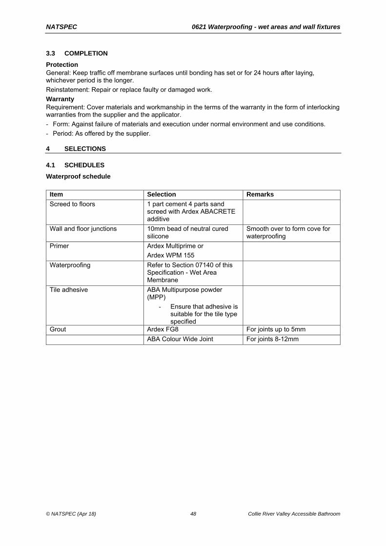
NATSPEC 0621 Waterproofing - wet areas and wall fixtures
© NATSPEC (Apr 18) 48 Collie River Valley Accessible Bathroom
3.3 COMPLETION
Protection General: Keep traffic off membrane surfaces until bonding has set or for 24 hours after laying, whichever period is the longer.
Reinstatement: Repair or replace faulty or damaged work.
Warranty Requirement: Cover materials and workmanship in the terms of the warranty in the form of interlocking warranties from the supplier and the applicator.
- Form: Against failure of materials and execution under normal environment and use conditions.
- Period: As offered by the supplier.
4 SELECTIONS
4.1 SCHEDULES
Waterproof schedule
Item Selection Remarks
Screed to floors 1 part cement 4 parts sand screed with Ardex ABACRETE additive
Wall and floor junctions 10mm bead of neutral cured silicone
Smooth over to form cove for waterproofing
Primer Ardex Multiprime or
Ardex WPM 155
Waterproofing Refer to Section 07140 of this Specification - Wet Area Membrane
Tile adhesive ABA Multipurpose powder (MPP)
- Ensure that adhesive is suitable for the tile type specified
Grout Ardex FG8 For joints up to 5mm
ABA Colour Wide Joint For joints 8-12mm

NATSPEC 0631 Ceramic tiling and wall fixtures
© NATSPEC (Apr 18) 49 Collie River Valley Accessible Bathroom
0631 CERAMIC TILING
1 GENERAL
1.1 STANDARDS
Tiling General: Conform to the recommendations of AS 3958.1.
2 PRODUCTS
2.1 TILES AND ACCESSORIES
Tiles Standard: To AS ISO 13006.
Coves, nosings and skirtings: Provide matching stop-end and internal and external angle tiles moulded for that purpose.
Exposed edges: Purpose-made border tiles with the exposed edge (whether round, square or cushion) glazed to match the tile face. If such tiles are not available, mitre tiles on external corners.
Accessories General: If available, provide tile accessories such as round edge ceramic tiles, cove tiles, step treads and nosings to stairs, landings, and thresholds, skirtings, sills, copings and bath vents, which match the surrounding tiles, composition, colour and finish.
Slip resistance Stair treads, ramps and landings: Classification to AS 4586.
2.2 MATERIALS
Adhesives Standard: To AS ISO 13007.1.
PVA (polyvinyl acetate)-based adhesives: Do not use in wet areas or externally.
Mortar materials Cement type to AS 3972: GP.
Sand: Fine aggregate with a low clay content selected for grading, sharp and free from efflorescing salts.
Bedding mortar Mix proportion (cement:sand), by volume: Select proportions from the range 1:3 to 1:4 for satisfactory adhesion. Provide minimum water.
Water General: Clean and free from any deleterious matter.
Grout Cement-based proprietary grout: Mix with water. Fine sand may be added as a filler in wider joints.
Terracotta tiles: Provide proprietary polymer modified grout.
General purpose cement based grout: Mix with fine sand. Provide minimum water consistent with workability.
Pigments for coloured grout: Colourfast fillers compatible with the grout material. For cement-based grouts, provide lime-proof natural or synthetic metallic oxides compatible with cement.
3 EXECUTION
3.1 SUBSTRATES
Drying and shrinkage General: Before tiling, allow at least the following times to elapse (for initial drying out and shrinkage) for these substrates:
- Concrete slabs: 42 days.
NATSPEC 0631 Ceramic tiling and wall fixtures
© NATSPEC (Apr 18) 50 Collie River Valley Accessible Bathroom
- Concrete blockwork: 28 days.
- Toppings on slabs and rendering on brick or blockwork: A further 21 days.
- Rendering on swimming pool shell: A further 21 days minimum.
3.2 PREPARATION
Substrates without wet area membranes General: Conform to the following:
- Clean off any deposit or finish which may impair adhesion or location of tiles.
- If framed or discontinuous, support members are in full lengths without splicing.
- If solid or continuous:
. Remove excessive projections.
. Fill voids and hollows greater than 10 mm with abrupt edges with a cement:sand mix not stronger than the substrate or weaker than the bedding.
. Fill depressions less than 10 mm with a latex modified cementitious product and eliminate feathering by scabbling the edges.
Absorbent substrates: If suction is excessive, control it by dampening but avoid over-wetting and do not apply mortar bedding to substrates showing surface moisture.
Dense concrete: If not sufficiently rough to provide a mechanical key, roughen by scabbling or the like to remove 3 mm of the surface and expose the aggregate; then apply a bonding treatment.
Substrates with wet area membranes General: Make sure substrates are as follows:
- Clean and free of any deposit or finish which may impair adhesion or location of tiles.
- Compatible with all components of the floor system.
3.3 TILING GENERALLY
Cutting and laying Cutting: Cut tiles neatly to fit around fixtures and fitting and at margins where necessary. Drill holes without damaging tile faces. Cut recesses for fittings such as soap holders. Rub edges smooth without chipping.
Laying: Return tiles into sills, reveals and openings. Butt up to returns, frames, fittings, and other finishes. Strike and point up beds where exposed. Remove tile spaces before grouting.
Variations General: Distribute variations in hue, colour, or pattern uniformly, by mixing tiles or tile batches before laying.
Protection Floor tiles: Keep traffic off floors until the bedding has set and attained its working strength.
Floor finish dividers General: Finish tiled floors at junctions with differing floor finishes with a corrosion-resistant metal dividing strip fixed to the substrate. If changes of floor finish occur at doorways, make the junction directly below the closed door.
Bath ventilation General: Ventilate the space below fully enclosed baths with at least 2 vermin proofed ventilating tiles.
3.4 SETTING OUT
Tile joints Joint widths: Set out tiles to give uniform joint widths within the following limits:
- Floors:
. Dry pressed tiles: 3 mm.
. Extruded tiles: 6 mm.
. Vitrified: 3 to 5 mm.
. Quarry tiles: 6 to 12 mm.
- Mounted mosaics: To match mounting pattern.
- Walls:

NATSPEC 0631 Ceramic tiling and wall fixtures
© NATSPEC (Apr 18) 51 Collie River Valley Accessible Bathroom
. Dry pressed tile: 1.5 mm.
. Extruded tile: 6 mm.
Joint alignment: Set out tiling with joints accurately aligned in both directions and wall tiling joints level and plumb.
Joint position: Set out tiles from the centre of the floor or wall to be tiled and, if possible, make sure cut tiles are a half tile or larger.
Fixtures: If possible, position tiles so that holes for fixtures and other penetrations occur at the intersection of horizontal and vertical joints or in the centre of tiles.
Falls and levels General: Grade floor tiling to even and correct falls generally and to floor wastes and elsewhere as required. Make level junctions with walls. If falls are not required, lay level.
Fall, general: 1:100 minimum.
Fall, in shower areas: 1:60 minimum.
Change of finish: Maintain finished floor level across changes of floor finish including carpet.
3.5 BEDDING
Preparation of tiles Adhesive bedding: Fix tiles dry; do not soak.
Mortar bedding: Soak porous tiles in water for half an hour and then drain until the surface water has disappeared.
Terracotta tiles: Use pre-sealed tiles or apply a breathable sealer and lay dry. If a final sealed finish is selected, use a compatible laying sealer.
Bedding General: Use bedding methods and materials which are appropriate to the tile, the substrate, the conditions of service, and which leave the tile firmly and solidly bedded in the bedding material and adhered to the substrate. Form falls integral with the substrate.
3.6 GROUTED AND SEALANT JOINTS
Grouted joints General: Commence grouting as soon as practicable after bedding has set. Clean out joints as necessary before grouting.
Face grouting: Fill the joints solid and tool flush. Clean off surplus grout. Wash down when the grout has set. When grout is dry, polish the tiled surface with a grout film remover and clean cloth.
Sealant joints General: Provide sealant joints filled with sealant and finished flush with the tile surface as follows:
- Where tiling is cut around sanitary fixtures.
- At corners of walls in showers.
- Around fixtures interrupting the tile surface, for example pipes, brackets, bolts and nibs.
- At junctions with elements such as window and door frames and built-in cupboards.
Material: Anti-fungal modified silicone.
Width: 5 mm.
Depth: Equal to the tile thickness.
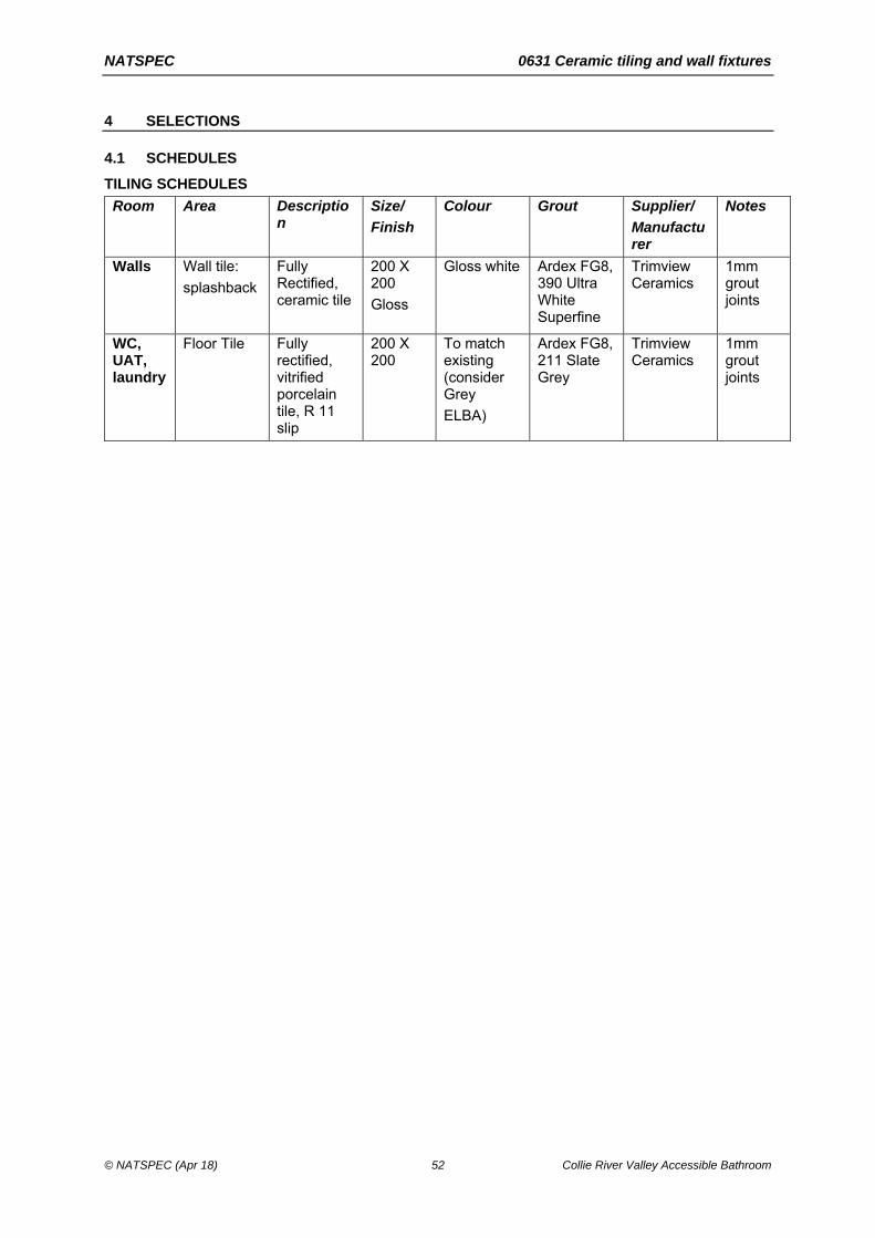
NATSPEC 0631 Ceramic tiling and wall fixtures
© NATSPEC (Apr 18) 52 Collie River Valley Accessible Bathroom
4 SELECTIONS
4.1 SCHEDULES
TILING SCHEDULES
Room Area Description
Size/
Finish
Colour Grout Supplier/
Manufacturer
Notes
Walls Wall tile:
splashback
Fully Rectified, ceramic tile
200 X 200
Gloss
Gloss white Ardex FG8, 390 Ultra White Superfine
Trimview Ceramics
1mm grout joints
WC, UAT, laundry
Floor Tile Fully rectified, vitrified porcelain tile, R 11 slip
200 X 200
To match existing (consider Grey
ELBA)
Ardex FG8, 211 Slate Grey
Trimview Ceramics
1mm grout joints

NATSPEC 0671 Painting and wall fixtures
© NATSPEC (Apr 18) 53 Collie River Valley Accessible Bathroom
0671 PAINTING
1 GENERAL
1.1 STANDARDS
Painting General: To the recommendations of those parts of AS/NZS 2311 referenced in this worksection.
2 PRODUCTS
2.1 PAINTING MATERIAL
Paint brand Quality: If the product is offered in a number of levels of quality, provide premium quality lines.
Handling Delivery: Deliver paints to the site in the manufacturer's labelled and unopened containers.
Low VOC emitting paints VOC limits for low odour/low environmental impact paint types:
- Primers and undercoats: < 65 g/litre.
- Low gloss white or light coloured latex paints for wall areas: < 16 g/litre.
- Coloured low gloss latex paints: < 16 g/litre.
- Gloss latex paints for timber doors and trims: < 75 g/litre.
Combinations General: Do not combine products from different manufacturers in a system.
Clear timber finish systems: Provide only the combinations of putty, stain and sealer recommended by the manufacturer of the top coats.
Putty and fillers Material: To the recommendation of the paint system manufacturer as suitable for the substrate and compatible with the primer.
Tinting General: Provide only products which are colour tinted by the manufacturer or supplier.
3 EXECUTION
3.1 PREPARATION
Order of work Other trades: Before painting, complete the work of other trades as far as practicable within the area to be painted, except for the installation of fittings, floor sanding and laying flooring materials.
Clear finishes: Complete clear timber finishes before commencing opaque paint finishes in the same area.
Protection General: Before painting, clean the area and protect from dust contamination. Use drop sheets and masking agents to protect surfaces, including finished surfaces and adjacent surfaces during painting.
Fixtures and furniture: Remove door furniture, switch plates, light fittings and other fixtures before painting, and refix in position on completion of painting.
Wet paint warning Notice: Place in a conspicuous location and do not remove until the paint is dry.
Substrate preparation - generally General: Prepare substrates to receive the painting systems.
Cleaning: Clean down the substrate surface. Do not cause damage to the substrate or the surroundings.

NATSPEC 0671 Painting and wall fixtures
© NATSPEC (Apr 18) 54 Collie River Valley Accessible Bathroom
Filling: Fill cracks and holes with fillers, sealants, putties or grouting cements as appropriate for the finishing system and substrate, and sand smooth.
- Clear finish: Provide filler tinted to match the substrate.
Clear timber finish systems: Prepare the surface so that its attributes will show through the clear finish without blemishes, using methods including the following:
- Removal of bruises.
- Removal of discolourations, including staining by oil, grease and nailheads.
- Bleaching where necessary to match the timber colour sample.
- Puttying.
- Fine sanding, with the last abrasive no coarser than 220 grit, so that there are no scratches across the grain.
Unpainted surfaces Standard: To AS/NZS 2311 Section 3.
Previously painted surfaces Preparation of a substrate in good condition: To AS/NZS 2311 clause 7.4.
Preparation of a substrate in poor condition: To AS/NZS 2311 clause 7.5.
Preparation of steel substrates with protective coatings: To AS 2312.1 Section 8 and AS 1627.1.
3.2 PAINTING
Light levels General: ≥ 400 lux.
Paint application Standard: To AS/NZS 2311 Section 6.
Timing: Apply the first coat immediately after substrate preparation and before contamination of the substrate can occur. Apply subsequent coats after the manufacturer’s recommended drying period has elapsed.
Priming before fixing General: Apply one coat of wood primer (2 coats to end grain) to the back of the following before fixing in position:
- External fascia boards.
- Timber door and window frames.
- Bottoms of external doors.
- Associated trims and glazing beads.
- Timber board cladding.
Spraying General: If the paint application is by spraying, use conventional or airless equipment that conforms to the following:
- Satisfactorily atomises paint being applied.
- Does not require paint to be thinned beyond the maximum amount recommended by the manufacturer.
- Does not introduce oil, water or other contaminants into the applied paint.
Paint with known health hazards: Not permitted on site.
Sanding Clear finishes: Sand the sealer, using abrasive no coarser than 320 grit, without cutting through the colour. Take special care with round surfaces and edges.
Repair Requirement: Clean off marks, paint spots and stains progressively and restore damaged surfaces to their original condition. Touch up new damaged decorative paintwork or misses with the paint batch used in the original application.
Repair of galvanizing Cleaning: For galvanized surfaces which have been subsequently welded, or which have been welded, prime the affected area.

NATSPEC 0671 Painting and wall fixtures
© NATSPEC (Apr 18) 55 Collie River Valley Accessible Bathroom
Primer: Type 2 organic zinc rich coating for the protection of steel to AS/NZS 3750.9.
Tinting General: Tint each coat of an opaque coating system so that each has a noticeably different tint from the preceding coat, except for top coats in systems with more than one top coat.
Services General: Paint new services and equipment if not embedded, except chromium, anodised aluminium, GRP, PVC-U, stainless steel, non-metallic flexible materials and normally lubricated machined surfaces. Repaint proprietary items only if damaged.
3.3 PAINT SYSTEMS
Paint system description Generally: The paint system is referred to by its final coat.
Primers and undercoats: Provide primers and undercoats recommended by the manufacturer of the selected final coat as suitable for the substrate and the final coat.
Number of coats: Unless specified as one or two coat systems, each paint system consists of at least 3 coats.
Selection: Provide paint systems that conforms to the Paint final coat table.
Paint final coat table
Final coat Applicable Australian Standard
Interior
Flat latex AS 3730.1
Floor varnish - moisture cured AS 3730.27
Floor varnish - two pack isocyanate cured AS 3730.27
Low gloss latex AS 3730.3
Semi-gloss latex AS 3730.2
Gloss latex AS 3730.12
Exterior
Full gloss solvent-borne AS 3730.6
Flat latex AS 3730.7
Low gloss latex AS 3730.8
Gloss latex AS 3730.10
Stain, lightly pigmented AS 3730.28
Latex stain, opaque AS 3730.16
Semi-gloss latex AS 3730.9
Paving
Paving paint, semi-gloss AS 3730.29
Paving paint, gloss AS 3730.29

NATSPEC 0671 Painting and wall fixtures
© NATSPEC (Apr 18) 56 Collie River Valley Accessible Bathroom
4 SELECTIONS
4.1 SCHEDULES
PAINTING SCHEDULE
Doors Lightly sand surface
Dulux specification code AUSD3200
Coating System Summary
1st Coat: AUDD1169: Dulux Professional Total Prep
2nd Coat: AUDD1282: Dulux Aquanamel Gloss
3rd Coat: AUDD1282: Dulux Aquanamel Gloss
Wet area walls Dulux specification code AUSD4611
Coating System Summary
Primer: AUDD1449: Dulux Professional Enviro2 Water Based Sealer Binder
2nd Coat: AU_DD02074: Dulux Wash&Wear +Plus Kitchen & Bathroom Low Sheen
3rd Coat: AU_DD02074: Dulux Wash&Wear +Plus Kitchen & Bathroom Low Sheen
Steel door frames Degrease & lightly sand surface
Non galvanised interior steelwork
Prepare as per Protective Treatment under Structural Steel Specification Section then finish as follows:
Dulux specification code AU_SD07570
Coating System Summary -
1st Coat: AUDI1136: Dulux Luxaprime Zinc Phosphate Primer
2nd Coat: AUDD1282: Dulux Aquanamel Gloss
3rd Coat: AUDD1282: Dulux Aquanamel Gloss
All Colours to match existing.

NATSPEC 0802 Hydraulic design and install and wall fixtures
© NATSPEC (Apr 18) 57 Collie River Valley Accessible Bathroom
0802 HYDRAULIC DESIGN AND INSTALL
1 GENERAL
1.1 STANDARDS
General Plumbing and drainage: To the AS/NZS 3500 series.
Authorised products: Listed in the WaterMark Product Database, unless otherwise required by the network utility operator.
2 EXECUTION
2.1 INSTALLATION
Connections to Network Utility Operator mains General: Excavate to locate and expose the connection points and connect to the Network Utility Operator mains. On completion, backfill and compact the excavation and reinstate surfaces and elements which have been disturbed such as roads, pavements, kerbs, footpaths and nature strips.
Piping Requirement: Install piping in straight lines and to uniform grades. Arrange and support the piping so that it remains free from vibration and water hammer, while permitting thermal movement. Keep the number of joints to a minimum. Prevent direct contact between incompatible metals.
Embedded pipes: Do not embed pipes that operate under pressure in concrete or surfacing material.
Concealment: If practicable, conceal piping and fittings requiring maintenance or servicing so that they are accessible within non-habitable enclosed spaces such as roof spaces, subfloor spaces and ducts. Keep pipelines in subfloor spaces at least 150 mm above ground and make sure access can be provided throughout for inspection. Provide at least 25 mm clearance between adjacent pipelines (measured from the piping insulation where applicable).
Building penetrations: If piping or conduit penetrates building elements, provide metal or PVC-U sleeves formed from oversized pipe sections.
Cover plates: If exposed piping emerges from wall, floor or ceiling finishes, provide cover plates of non-ferrous metal, finished to match the piping, or of stainless steel.
Pipe support materials: The same as the piping, or galvanized or non-ferrous metals, with bonded PVC-U or glass fibre woven tape sleeves where needed to separate dissimilar metals.
2.2 FINISHES
General Requirement: Finish exposed piping, including fittings and supports as follows:
- In internal locations such as toilet and kitchen areas: Chrome plate copper piping to AS 1192 service condition 2, bright.
- Externally and steel piping or worn fittings internally: Paint.
- In concealed but accessible spaces (including cupboards and non-habitable enclosed spaces): Leave copper and plastic unpainted except for required identification marking. Prime steel piping and iron fittings.
- Valves: Finish valves to match connected piping.
2.3 COLD AND HEATED WATER
Standards General: To AS/NZS 3500.1 and AS/NZS 3500.4.
Copper pipe: To AS 4809.
Pipe material General: Provide pipework for the reticulation of cold and heated water and to the Plumbing systems schedule.

NATSPEC 0802 Hydraulic design and install and wall fixtures
© NATSPEC (Apr 18) 58 Collie River Valley Accessible Bathroom
Tap positions Requirement: Locate hot tap to the left of, or above, the cold water tap.
Fittings and accessories General: Provide the accessories and fittings necessary for the proper functioning of the plumbing systems, including taps, valves, outlets, pressure and temperature control devices, strainers, gauges and pumps.
Water heaters Location: Locate water heaters where they can be maintained or replaced without damaging adjacent structures, fixtures or finishes.
Types:
- Electric water heaters: To AS/NZS 4692.1.
. Energy performance: To AS/NZS 4692.2.
- Gas hot water heaters: To AS/NZS 5263.1.2. If a flue damper is available for the water heater supplied, provide one.
. Energy performance: To AS 4552.2.
- Solar water heaters: To AS/NZS 2712.
- Heat pump water heaters: To AS/NZS 2712.
Tariff: Install so that the heating system qualifies for the tariff concession or subsidy offered by the statutory authority.
Isolating valves: Provide isolation valves to water heaters.
Heated water temperature Standard: To AS/NZS 3500.4.
Maximum temperature at ablution outlets: 50°C.
Maximum recommended temperature at kitchen sinks and laundry tubs: 60°C.
Hot water temperature control Requirement: Provide thermostatic mixing valves or special taps that automatically control the temperature at the mixed outlet to a preselected temperature.
Cleaning General: On completion, flush the pipelines using water and leave pipelines clean.
2.4 STORMWATER
Standards General: To AS/NZS 3500.3.
Cleaning General: During construction, use temporary covers to openings and keep the system free of debris. On completion, clean and flush the system.
Pipe laying General: Lay pipelines with the spigot ends in the direction of flow.
Downpipe connections General: Turn up drain branch pipelines to finish 50 mm above finished ground or pavement level.
Subsoil drains Connection: Connect subsoil drains to the stormwater drainage system.
Trench width: Minimum 450 mm.
Subsoil drains: Provide proprietary perforated plastic pipe.
Filter fabric: Provide a polymeric fabric formed from a plastic yarn containing stabilisers or inhibitors to make the filaments resistant to deterioration due to ultraviolet light.
Filter sock: Provide a polyester permeable sock capable of retaining particles of 0.25 mm size. Securely fit or join the sock at each joint.
Pits Cover levels: Locate the top of covers or gratings, including frames as follows:
- In paved areas: Flush with the paving surface.
- In landscaped areas: 25 mm above finished surface.

NATSPEC 0802 Hydraulic design and install and wall fixtures
© NATSPEC (Apr 18) 59 Collie River Valley Accessible Bathroom
- Gratings taking surface water runoff: Set to receive the runoff without ponding.
2.5 WASTEWATER
Standards General: To AS/NZS 3500.2.
Waterless composting toilets: To AS/NZS 1546.2.
On-site domestic wastewater treatment units: To AS/NZS 1546.3.
Cleaning During construction: Use temporary covers to openings and keep the system free of debris.
On completion: Clean and flush the system.
Septic tanks Standard: To AS/NZS 1546.1.
Effluent disposal: To AS 1547.
Vent pipes Staying to roof: If fixings for stays penetrate the roof covering, seal the penetrations and make watertight.
Terminations: Provide bird-proof vent cowls made of the same material and colour as the vent pipe.
2.6 RAINWATER TANKS
Standards Metal tanks and rainwater goods: To AS/NZS 2179.1.
Design and installation: To the recommendations of SAA HB 230.
Polyethylene tanks: To AS/NZS 4766.
Coated steel tanks: Metallic-coated steel with polymer film to AS 2070 on the inside and prepainted on the outside.
Bladder tanks: Proprietary plastic bladder type constructed from polymer conforming to AS 2070, resistant to puncture and microbial attack.
Rainwater tanks Accessories: Provide accessories needed to complete the installation and constructed from corrosion resistant material compatible with the tank material. Include the following:
- Inlet and outlet connections.
- Floating outlet to draw water from the upper part of the tank.
- Tight fitting lids or insect proof screens at all openings.
- Flap valves at every opening to the tank.
- Calmed inlet to the tank to prevent stirring sediment.
- Flywire screened overflow siphon to skim surface contaminants.
- Vermin proof, childproof access opening.
- Easily cleanable filter before the entry to the tank with maximum 1 mm mesh size.
First flush diverter General: Provide a first flush diverter. Arrange to drain completely.
Sizing: Select for at least 20 L/100 m2 rainwater catchment area.
Construction: Corrosion resistant and compatible with the rainwater plumbing and tank.
Discharge: Discharge waste water from the first flush diverter either:
- If permitted by the local authority, onto grassed areas away from tank and building footings.
- To the stormwater installation.
Installation Requirement: Provide structural support to withstand the mass of the tank when full without deformation or excessive settling. Support connecting piping independently of the tank. Provide a 300 mm long section of reinforced flexible hose to prevent piping exerting a load on the tank. Pipe overflow to discharge away from the tank. Prevent the entry of sunlight to the interior of the tank.
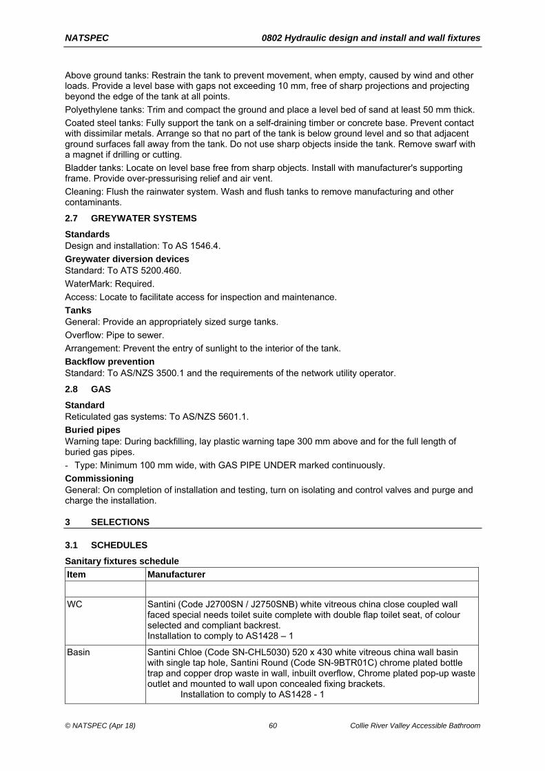
NATSPEC 0802 Hydraulic design and install and wall fixtures
© NATSPEC (Apr 18) 60 Collie River Valley Accessible Bathroom
Above ground tanks: Restrain the tank to prevent movement, when empty, caused by wind and other loads. Provide a level base with gaps not exceeding 10 mm, free of sharp projections and projecting beyond the edge of the tank at all points.
Polyethylene tanks: Trim and compact the ground and place a level bed of sand at least 50 mm thick.
Coated steel tanks: Fully support the tank on a self-draining timber or concrete base. Prevent contact with dissimilar metals. Arrange so that no part of the tank is below ground level and so that adjacent ground surfaces fall away from the tank. Do not use sharp objects inside the tank. Remove swarf with a magnet if drilling or cutting.
Bladder tanks: Locate on level base free from sharp objects. Install with manufacturer's supporting frame. Provide over-pressurising relief and air vent.
Cleaning: Flush the rainwater system. Wash and flush tanks to remove manufacturing and other contaminants.
2.7 GREYWATER SYSTEMS
Standards Design and installation: To AS 1546.4.
Greywater diversion devices Standard: To ATS 5200.460.
WaterMark: Required.
Access: Locate to facilitate access for inspection and maintenance.
Tanks General: Provide an appropriately sized surge tanks.
Overflow: Pipe to sewer.
Arrangement: Prevent the entry of sunlight to the interior of the tank.
Backflow prevention Standard: To AS/NZS 3500.1 and the requirements of the network utility operator.
2.8 GAS
Standard Reticulated gas systems: To AS/NZS 5601.1.
Buried pipes Warning tape: During backfilling, lay plastic warning tape 300 mm above and for the full length of buried gas pipes.
- Type: Minimum 100 mm wide, with GAS PIPE UNDER marked continuously.
Commissioning General: On completion of installation and testing, turn on isolating and control valves and purge and charge the installation.
3 SELECTIONS
3.1 SCHEDULES
Sanitary fixtures schedule
Item Manufacturer
WC Santini (Code J2700SN / J2750SNB) white vitreous china close coupled wall faced special needs toilet suite complete with double flap toilet seat, of colour selected and compliant backrest. Installation to comply to AS1428 – 1
Basin Santini Chloe (Code SN-CHL5030) 520 x 430 white vitreous china wall basin with single tap hole, Santini Round (Code SN-9BTR01C) chrome plated bottle trap and copper drop waste in wall, inbuilt overflow, Chrome plated pop-up waste outlet and mounted to wall upon concealed fixing brackets.
Installation to comply to AS1428 - 1

NATSPEC 0802 Hydraulic design and install and wall fixtures
© NATSPEC (Apr 18) 61 Collie River Valley Accessible Bathroom
Tapware and spouts schedule
Item
Basin Santini Kyla (Code SN-KAYDBM) chrome plated single lever basin mixer with extended disabled lever action handle and aerator nozzle. Installation to comply to AS1428 - 1
WC 15Ø C/p mini stopcock with Zurn stainless steel braided high pressure hose connection to cistern inlet valve.
Shower Provide and install Caroma Acqua shower mixer with Starion Starsafe Virtu shower set with stainless steel shower / support rails, 1500 long robust silver hose and adjustable hand shower head, or a similar product equivalent in function, quality, etc to the approval of the Superintendent.

NATSPEC 0902 Electrical design and install and wall fixtures
© NATSPEC (Apr 18) 62 Collie River Valley Accessible Bathroom
0902 ELECTRICAL DESIGN AND INSTALL
1 GENERAL
1.1 STANDARDS
General Electrical installation: To AS/NZS 3000 and SAA HB 301.
Electrical cable selection: To AS/NZS 3008.1.1.
Telecommunications cabling: To AS/CA S008, AS/CA S009, AS/NZS 3080, and SAA HB 252.
1.2 INTERPRETATION
Abbreviations General: For the purposes of this worksection the following abbreviations apply:
- ED S&IR: The Electricity Distributor’s Service and Installation Rules.
- RCD: Residual Current Device.
Definition General: For the purposes of this worksection the following definitions apply:
- Telephony: Speech and low band frequencies (= 100 kHz).
2 EXECUTION
2.1 GENERAL
Applications and compliance General: Submit all necessary applications for electricity supply. Liaise with the electricity distributor and comply with the ED S&IR.
Consumers mains and metering General: Provide consumers mains and connect them to the electricity distributor mains.
Electricity distributor’s requirements: Provide metering, protection, and control equipment as required by the ED SI&R .
Switchboards Standard: To AS/NZS 3439.3 or AS/NZS 61439.3.
Construction: Enclosed type with a hinged lid. Provide circuit breakers and RCDs.
Location: Verify that the location selected is compliant before proceeding.
Maximum demand and spare capacity General: Calculate the maximum demand of the installation in accordance with AS/NZS 3000 and provide a copy of the calculations.
Spare capacity: Provide the following:
- > 10% spare capacity in mains and submains.
- > 25% spare capacity in final subcircuits.
Load balancing: Spread electrical load equally across circuits to prevent overloading and inadvertent circuit breaker operation.
Fixed and stationary appliances: Treat socket outlets supplying fixed or stationary appliances likely to cause an RCD to trip due to earth leakage currents in accordance with AS/NZS 3000. Do not connect to circuits that supply socket outlets intended for hand held or portable appliances.
Spare spaces: Provide switchboards with ≥ 25% spare positions for future single phase circuit breakers.
Accessories General: Provide accessories necessary for a complete installation including but not limited to switches, dimmers, socket outlets, and telecommunications outlets. Provide accessories located in close proximity of the same size and material and from the same manufacture.

NATSPEC 0902 Electrical design and install and wall fixtures
© NATSPEC (Apr 18) 63 Collie River Valley Accessible Bathroom
Mounting: Flush mount accessories to the wall (or ceiling) unless noted otherwise. Provide proprietary wall boxes in masonry and wall brackets in stud walls.
Wet areas: Position accessories in locations containing baths showers or other fixed water containers to comply with the requirements of AS/NZS 3000.
Wiring Concealed cables and conduits: Provide conduits as necessary to allow wiring replacement without structural work or the removal of cladding, lining, plaster or cement rendering.
Sequence of work: Install conduits and cables before the installation of wall and ceiling linings, and before any external landscaping works.
Installation: Do not penetrate damp-proof courses. Arrange wiring such that it does not bridge the cavity in external masonry.
Conduit sizes: Provide conduits of sufficient internal diameter and arranged so that cables are not subject to undue mechanical stress during installation.
Minimum conduit diameter: 20 mm.
Conduits for future use: Provide a non-metallic drawstring having a breaking strain > 100 kg.
Luminaires Standard: to AS/NZS 60598.1.
Non-specified luminaires: Provide a bayonet cap batten holder and lamp at each lighting point location where no luminaire is documented.
Minimum energy performance standards:
- General: To AS/NZS 4782.2 and AS/NZS 4783.2.
- Self-ballasted lamps: To AS/NZS 4847.2.
- Incandescent lamps: To AS 4934.2.
Lighting control systems General: Locate grouped dimmers and control devices for future access. Provide ventilation and acoustic treatment to suit the device characteristics.
Appliances General: Provide final subcircuits and terminate at fixed appliances, hot water units, packaged air conditioning and other plant and equipment.
Isolation switch: Provide isolating switch adjacent to equipment.
Telecommunications Submissions: Submit required applications for telecommunications services to the telecommunications services carrier and liaise with the carrier.
Installations requiring telephony only: To AS/CA S009.
Small office/home office installations: Category 6, to AS/CA S009 and AS/NZS ISO/IEC 15018.
Television systems General: Provide a digital television distribution system to AS/NZS 1367 and conforming to the recommendations of Broadcast Australia and ACMA.
Antennas: Provide and locate antennas to receive all locally available free-to-air television stations.
Network systems General: Provide a coaxial cabling system suitable for satellite or cable network operator’s services.
Conduits for future cabling: ≥ 25 mm diameter with drawstrings.
Intruder alarm system General: Provide intruder alarm system.
Standard: To AS/NZS 2201.1.
Smoke detection system General: Provide smoke alarms to the requirements of the BCA 3.7.2. Connect smoke alarms to mains power.
Labelling General: Provide labels including control and circuit equipment ratings, functional units, notices for operational and maintenance personnel, incoming and outgoing circuit rating, sizes and origin of supply.

NATSPEC 0902 Electrical design and install and wall fixtures
© NATSPEC (Apr 18) 64 Collie River Valley Accessible Bathroom
Telecommunications cables: Label telecommunications cables, cross connects and outlets in accordance with the requirements of AS/NZS 3080.
Label colours Generally: Black lettering on white background except as follows:
- Main switch and caution labels: Red lettering on white background.
- Danger, warning labels: White lettering on red background.
2.2 COMPLETION
Testing and certification Electrical installations: Test to AS/NZS 3017. Provide a certificate showing test results, certifying compliance with AS/NZS 3000.
Telecommunications cabling: To AS/NZS ISO/IEC 15018. Test the cable link performance at the maximum frequency and data rate for the cable class, and the cable category. Provide a certificate showing test results and certifying compliance with AS/NZS ISO/IEC 15018.
Submission: Provide ACMA Telecommunications Cabling Advice (TCA1) form.
Television and audio systems: To AS/NZS 1367. Test the complete television and audio system. Provide a certificate showing test results and certifying compliance.
3 SELECTIONS
Tenders to nominate selections for items all electrical items as per Architectural drawings. All to AS and BCA requirements.

APPENDIX 1 – PROPOSED LAYOUT

NATSPEC Appendix 1 – PROPOSED layout and wall fixtures
© NATSPEC (Apr 18) 66 Collie River Valley Accessible Bathroom

NATSPEC Appendix 2 – Existing Site Photos and wall fixtures
© NATSPEC (Apr 18) 67 Collie River Valley Accessible Bathroom
APPENDIX 2 – EXISTING SITE PHOTOS

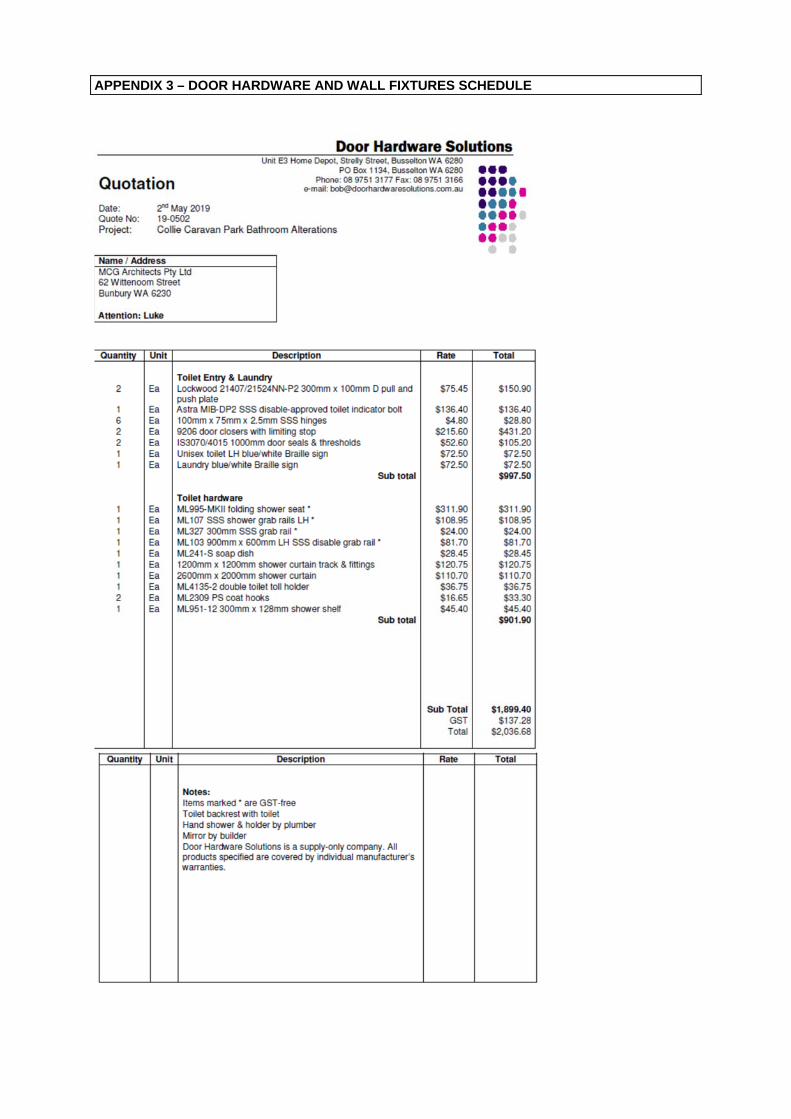
APPENDIX 3 – DOOR HARDWARE AND WALL FIXTURES SCHEDULE