college physics chapter 9 statics and torque powerpoint image slideshow
TRANSCRIPT

COLLEGE PHYSICSChapter 9 STATICS AND TORQUE
PowerPoint Image Slideshow

FIGURE 9.1
On a short time scale, rocks like these in Australia’s Kings Canyon are static, or motionless relative to the Earth. (credit: freeaussiestock.com)

FIGURE 9.2
This motionless person is in static equilibrium. The forces acting on him add up to zero. Both forces are vertical in this case.

FIGURE 9.3
This car is in dynamic equilibrium because it is moving at constant velocity. There are horizontal and vertical forces, but the net external force in any direction is zero. The applied force between the tires and the road is balanced by air friction, and the weight of the car is supported by the normal forces, here shown to be equal for all four tires.

FIGURE 9.4
An ice hockey stick lying flat on ice with two equal and opposite horizontal forces applied to it. Friction is negligible, and the gravitational force is balanced by the support of the ice (a normal force). Thus, net F = 0 . Equilibrium is achieved, which is static equilibrium in this case.

FIGURE 9.5
The same forces are applied at other points and the stick rotates—in fact, it experiences an accelerated rotation. Here net F = 0 but the system is not at equilibrium. Hence, the net F = 0 is a necessary—but not sufficient—condition for achieving equilibrium.

FIGURE 9.7
Torque is the turning or twisting effectiveness of a force, illustrated here for door rotation on its hinges (as viewed from overhead). Torque has both magnitude and direction. (a) Counterclockwise torque is produced by this force, which means that the door will rotate in a counterclockwise due to F . Note that r is the perpendicular distance of the pivot from the line of action of the force. (b) A smaller ⊥counterclockwise torque is produced by a smaller force F′ acting at the same distance from the hinges (the pivot point). (c) The same force as in (a) produces a smaller counterclockwise torque when applied at a smaller distance from the hinges. (d) The same force as in (a), but acting in the opposite direction, produces a clockwise torque. (e) A smaller counterclockwise torque is produced by the same magnitude force acting at the same point but in a different direction. Here, θ is less than 90º . (f) Torque is zero here since the force just pulls on the hinges, producing no rotation. In this case, θ = 0º .

FIGURE 9.8
A force applied to an object can produce a torque, which depends on the location of the pivot point.
(a) The three factors r , F , and θ for pivot point A on a body are shown here— r is the distance from the chosen pivot point to the point where the force F is applied, and θ is the angle between F and the vector directed from the point of application to the pivot point. If the object can rotate around point A, it will rotate counterclockwise. This means that torque is counterclockwise relative to pivot A.
(b) In this case, point B is the pivot point. The torque from the applied force will cause a clockwise rotation around point B, and so it is a clockwise torque relative to B.

FIGURE 9.9
Two children balancing a seesaw satisfy both conditions for equilibrium. The lighter child sits farther from the pivot to create a torque equal in magnitude to that of the heavier child.
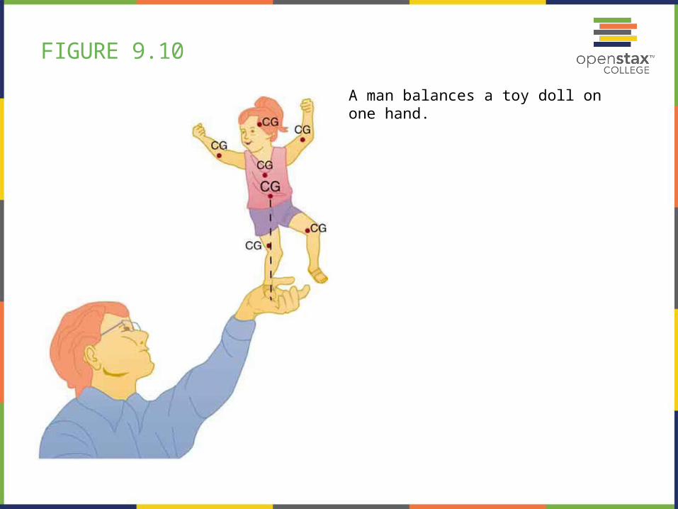
FIGURE 9.10
A man balances a toy doll on one hand.

FIGURE 9.11
This pencil is in the condition of equilibrium. The net force on the pencil is zero and the total torque about any pivot is zero.

FIGURE 9.12
If the pencil is displaced slightly to the side (counterclockwise), it is no longer in equilibrium. Its weight produces a clockwise torque that returns the pencil to its equilibrium position.

FIGURE 9.13
If the pencil is displaced too far, the torque caused by its weight changes direction to counterclockwise and causes the displacement to increase.

FIGURE 9.14
This figure shows unstable equilibrium, although both conditions for equilibrium are satisfied.

FIGURE 9.15
If the pencil is displaced even slightly, a torque is created by its weight that is in the same direction as the displacement, causing the displacement to increase.

FIGURE 9.16
(a) Here we see neutral equilibrium. The cg of a sphere on a flat surface lies directly above the point of support, independent of the position on the surface. The sphere is therefore in equilibrium in any location, and if displaced, it will remain put.
(b) Because it has a circular cross section, the pencil is in neutral equilibrium for displacements perpendicular to its length.
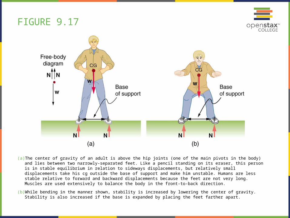
FIGURE 9.17
(a) The center of gravity of an adult is above the hip joints (one of the main pivots in the body) and lies between two narrowly-separated feet. Like a pencil standing on its eraser, this person is in stable equilibrium in relation to sideways displacements, but relatively small displacements take his cg outside the base of support and make him unstable. Humans are less stable relative to forward and backward displacements because the feet are not very long. Muscles are used extensively to balance the body in the front-to-back direction.
(b) While bending in the manner shown, stability is increased by lowering the center of gravity. Stability is also increased if the base is expanded by placing the feet farther apart.

FIGURE 9.18
The center of gravity of a chicken is below the hip joints. The chicken is in stable equilibrium. The body of the chicken is supported from above by the hips and acts as a pendulum between them.

FIGURE 9.19
A pole vaulter holds a pole horizontally with both hands.

FIGURE 9.20
A pole vaulter is holding a pole horizontally with both hands. The center of gravity is near his right hand.

FIGURE 9.21
A pole vaulter is holding a pole horizontally with both hands. The center of gravity is to the left side of the vaulter.

FIGURE 9.23
A nail puller is a lever with a large mechanical advantage. The external forces on the nail puller are represented by solid arrows. The force that the nail puller applies to the nail () is not a force on the nail puller. The reaction force the nail exerts back on the puller () is an external force and is equal and opposite to . The perpendicular lever arms of the input and output forces areand .

FIGURE 9.24
(a) In the case of the wheelbarrow, the output force or load is between the pivot and the input force. The pivot is the wheel’s axle. Here, the output force is greater than the input force. Thus, a wheelbarrow enables you to lift much heavier loads than you could with your body alone.
(b) In the case of the shovel, the input force is between the pivot and the load, but the input lever arm is shorter than the output lever arm. The pivot is at the handle held by the right hand. Here, the output force (supporting the shovel’s load) is less than the input force (from the hand nearest the load), because the input is exerted closer to the pivot than is the output.

FIGURE 9.25
(a) A crank is a type of lever that can be rotated 360º about its pivot. Cranks are usually designed to have a large MA.
(b) A simplified automobile axle drives a wheel, which has a much larger diameter than the axle. The MA is less than 1.
(c) An ordinary pulley is used to lift a heavy load. The pulley changes the direction of the force T exerted by the cord without changing its magnitude. Hence, this machine has an MA of 1.

FIGURE 9.26
(a) The combination of pulleys is used to multiply force. The force is an integral multiple of tension if the pulleys are frictionless. This pulley system has two cables attached to its load, thus applying a force of approximately . This machine has .
(b) Three pulleys are used to lift a load in such a way that the mechanical advantage is about 3. Effectively, there are three cables attached to the load.
(c) This pulley system applies a force of , so that it has . Effectively, four cables are pulling on the system of interest.

FIGURE 9.27
(a) The figure shows the forearm of a person holding a book. The biceps exert a force FB to support the weight of the forearm and the book. The triceps are assumed to be relaxed.
(b) Here, you can view an approximately equivalent mechanical system with the pivot at the elbow joint as seen in Example 9.4.

FIGURE 9.28
(a) Good posture places the upper body’s cg over the pivots in the hips, eliminating the need for muscle action to balance the body.
(b) Poor posture requires exertion by the back muscles to counteract the clockwise torque produced around the pivot by the upper body’s weight. The back muscles have a small effective perpendicular lever arm, rb ⊥ , and must therefore exert a large force Fb . Note that the legs lean backward to keep the cg of the entire body above the base of support in the feet.
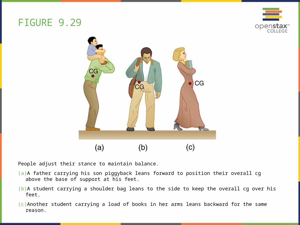
FIGURE 9.29
People adjust their stance to maintain balance.
(a) A father carrying his son piggyback leans forward to position their overall cg above the base of support at his feet.
(b) A student carrying a shoulder bag leans to the side to keep the overall cg over his feet.
(c) Another student carrying a load of books in her arms leans backward for the same reason.

FIGURE 9.30
This figure shows that large forces are exerted by the back muscles and experienced in the vertebrae when a person lifts with their back, since these muscles have small effective perpendicular lever arms. The data shown here are analyzed in the preceding example, Example 9.5.

FIGURE 9.31

FIGURE 9.32

FIGURE 9.33

FIGURE 9.34
A small drawbridge, showing the forces on the hinges ( F ), its weight ( w ), and the tension in its wires ( T ).
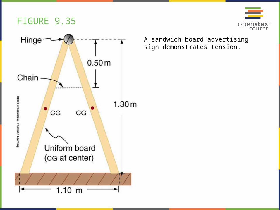
FIGURE 9.35
A sandwich board advertising sign demonstrates tension.
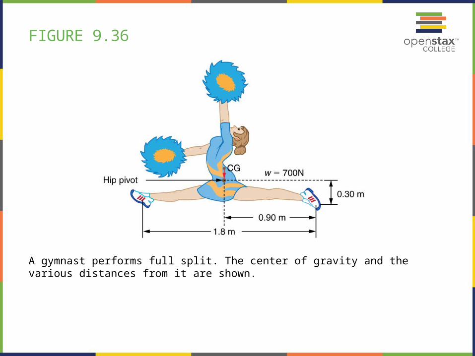
FIGURE 9.36
A gymnast performs full split. The center of gravity and the various distances from it are shown.

FIGURE 9.37
The Achilles tendon of the posterior leg serves to attach plantaris, gastrocnemius, and soleus muscles to calcaneus bone.

FIGURE 9.38
The knee joint works like a hinge to bend and straighten the lower leg. It permits a person to sit, stand, and pivot.

FIGURE 9.39
A mass is connected by pulleys and wires to the ankle in this exercise device.

FIGURE 9.40

FIGURE 9.41
The center of mass of the head lies in front of its major point of support, requiring muscle action to hold the head erect. A simplified lever system is shown.

FIGURE 9.42
The muscles in the back of the leg pull the Achilles tendon when one stands on one’s toes. A simplified lever system is shown.

FIGURE 9.43
A child being lifted by a father’s lower leg.

FIGURE 9.44
A person clenching a bullet between his teeth.

FIGURE 9.45
A woman doing pushups.