college college of dean: dr. karl stevens geomatic ... · introduction •“geomatics...
TRANSCRIPT

COLLEGE
COLLEGE OFENGINEERING & COMPUTER SCIENCE
DEAN: DR. KARL STEVENSDEAN: DR. KARL STEVENSASSOCIATE DEAN: DR. MOHAMMAD ILYAS
GEOMATIC ENGINEERING PROGRAM
INTERIM PROGRAM DIRECTOR: DR. DON LEONE P.E.
STAFF & FUTURE
ENGINEERS, SURVEYORS, ARCHITECTS&
SCIENTISTS
♦ SUE. RT and Geomatics Witten Technologies, Inc. R&D
(617) 236‐7103 ♦ http://www.wittentech.com
Nov. 13th, 2008 ♦ 2
SCIENTISTS

SUE, RT and Geomatics,
How do Subsurface Utility Engineering (SUE) and modern geophysical imaging techniq es s ch as Radar Tomograph (RT) relate to Geomatics?imaging techniques such as Radar Tomography (RT) relate to Geomatics?
Ralf Birken, Ph.D.Chief Scientist
♦ SUE. RT and Geomatics Witten Technologies, Inc. R&D
(617) 236‐7103 ♦ http://www.wittentech.com
Nov. 13th, 2008 ♦ 3
Chief Scientist

O U T L I N E
• IntroductionS b f Utilit E i i (SUE) d “ t bli h d” G h i• Subsurface Utility Engineering (SUE) and “established” Geophysics
• Modern Array-based Land-based Geophysical Methods– Radar TomographyRadar Tomography
• Concepts, Systems and Methodology, and Case Histories
– Electromagnetic Induction Arrays• Concepts, Systems and Methodology, and Case HistoriesConcepts, Systems and Methodology, and Case Histories
• SUE and the Impact of Geophysical Arrays– Legislation and Certification
• Summary
♦ SUE. RT and Geomatics Witten Technologies, Inc. R&D
(617) 236‐7103 ♦ http://www.wittentech.com
Nov. 13th, 2008 ♦ 4

Introduction
• “Geomatics Engineering”i d di i li hi h i t t i iti d li tis– is a modern discipline, which integrates acquisition, modeling, analysis, and management of spatially referenced data, i.e. data identified according to their locations. Based on the scientific f k f d it t t i l i i b d ga
ry.ca/abou
t/wha
framework of geodesy, it uses terrestrial, marine, airborne, and satellite-based sensors to acquire spatial and other data. It includes the process of transforming spatially referenced data f diff t i t i f ti t ith w
w.geo
matics.ucalg
from different sources into common information systems with well-defined accuracy characteristics."
• “Subsurface Geomatics” ?
http://w
w
Subsurface Geomatics ?– How do you acquire accurate surveying data of subsurface
features ?Wh t i t ?
♦ SUE. RT and Geomatics Witten Technologies, Inc. R&D
(617) 236‐7103 ♦ http://www.wittentech.com
Nov. 13th, 2008 ♦ 5
– What accuracies can you expect ?

Subsurface Utility Engineering (SUE) and “established” Geophysics“established” Geophysics
Greg JeffriesVice President
♦ SUE. RT and Geomatics Witten Technologies, Inc. R&D
(617) 236‐7103 ♦ http://www.wittentech.com
Nov. 13th, 2008 ♦ 6

SUE and “established” Geophysics
• Quality Level D (QL D):I f ti d i d f i ti d l Information derived from existing records or oral recollections.
• Quality Level C (QL C):Information obtained by surveying and plotting visible Information obtained by surveying and plotting visible above-ground utility features and by using professional judgment in correlating this information to QL D information.judgment in correlating this information to QL D information.
B d CI/ASCE 38 02 t d d d b A h
♦ SUE. RT and Geomatics Witten Technologies, Inc. R&D
(617) 236‐7103 ♦ http://www.wittentech.com
Nov. 13th, 2008 ♦ 7
Based on CI/ASCE 38-02 standards and summary by Anspach

SUE and “established” Geophysics
• Quality Level B (QL B):I f ti bt i d th h th li ti f i t Information obtained through the application of appropriate surface geophysical methods to determine the existence and approximate horizontal position of subsurface utilities and approximate horizontal position of subsurface utilities.
QL B data should be reproducible by surface geophysics at Q p y g p yany point of their depiction. This information is surveyed to applicable tolerances defined by the project and reduced onto plan documents.
B d CI/ASCE 38 02 t d d d b A h
♦ SUE. RT and Geomatics Witten Technologies, Inc. R&D
(617) 236‐7103 ♦ http://www.wittentech.com
Nov. 13th, 2008 ♦ 8
Based on CI/ASCE 38-02 standards and summary by Anspach

SUE and “established” Geophysics
• Quality Level A (QL A):Precise horizontal and vertical location of utilities obtained by the actual exposure (or verification of previously exposed and surveyed utilities) and subsequent measurement of subsurface utilities, usually at a specific point. Minimally intrusive excavation equipment is typically used to minimize the potential for utility damage A precise used to minimize the potential for utility damage. A precise horizontal and vertical location as well as other utility attributes is shown on plan documents. Accuracy is attributes is shown on plan documents. Accuracy is typically set at 15mm vertical, and to applicable horizontal survey and mapping.
♦ SUE. RT and Geomatics Witten Technologies, Inc. R&D
(617) 236‐7103 ♦ http://www.wittentech.com
Nov. 13th, 2008 ♦ 9
Based on CI/ASCE 38-02 standards and summary by Anspach

SUE and “established” Geophysics
• Commonly used geophysical methods:– Pipe and cable locators– Terrain conductivity meters
Metal detectors– Metal detectors– Ground Penetrating Radar (GPR)– Magnetic methodsMagnetic methods– Acoustic Methods– Optical systemsp y
♦ SUE. RT and Geomatics Witten Technologies, Inc. R&D
(617) 236‐7103 ♦ http://www.wittentech.com
Nov. 13th, 2008 ♦ 10
SUE and “established” Geophysics
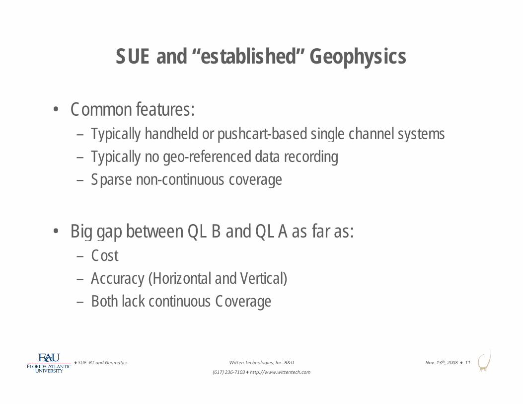
• Common features:– Typically handheld or pushcart-based single channel systems– Typically no geo-referenced data recording
Sparse non continuous coverage– Sparse non-continuous coverage
Bi b t QL B d QL A f • Big gap between QL B and QL A as far as:– Cost
Accuracy (Horizontal and Vertical)– Accuracy (Horizontal and Vertical)– Both lack continuous Coverage
♦ SUE. RT and Geomatics Witten Technologies, Inc. R&D
(617) 236‐7103 ♦ http://www.wittentech.com
Nov. 13th, 2008 ♦ 11

SUE and “established” Geophysics
• Suggestion to narrow gap between QL B and QL A using:A b d S f G h i l M th d– Array-based Surface Geophysical Methods
• As far as: QL AHigherAs far as:– Continuous
CoverageSUE Quality Levels
QL‐A
QL‐B
Higher
– Horizontal andVertical Position
– Cost versus Risk
COSTQL‐C
QL B
– Reusable geo-referenced digital data
QL‐D
Lower i h
♦ SUE. RT and Geomatics Witten Technologies, Inc. R&D
(617) 236‐7103 ♦ http://www.wittentech.com
Nov. 13th, 2008 ♦ 12
digital data RISKLower Higher

References
• American Society of Civil Engineers (2002). C/I ASCE 38-02 St d d G id li f th C ll ti d D i ti f 02, Standard Guideline for the Collection and Depiction of Existing Subsurface Utility Data. Reston, VA.A h J H 2002 (?) U d d tilit it i • Anspach, J.H., 2002 (?), Underground utility security issues at critical facilities: ?, 5 pages.
♦ SUE. RT and Geomatics Witten Technologies, Inc. R&D
(617) 236‐7103 ♦ http://www.wittentech.com
Nov. 13th, 2008 ♦ 13

Modern Array-based Land-based Geophysical Methods
• Multi-channel geophysical systems• Deployed through vehicle (some even within traffic flow)• Movement tracked through survey-grade positioning system• Create accurate geo-referenced digital data sets• Able to cover large areas efficiently with dense continuous data
coverage• Allow more advanced methods of data interpretationp• Option to combine multiple arrays in single data collection effort• Surveyor certified accuracy and final maps
♦ SUE. RT and Geomatics Witten Technologies, Inc. R&D
(617) 236‐7103 ♦ http://www.wittentech.com
Nov. 13th, 2008 ♦ 14
Surveyor certified accuracy and final maps

Radar Tomography (RT)g p y ( )
Concept
♦ SUE. RT and Geomatics Witten Technologies, Inc. R&D
(617) 236‐7103 ♦ http://www.wittentech.com
Nov. 13th, 2008 ♦ 15

Common 2D GPR Survey Grids
2 feet or more between profiles
4 inches or more between t i ( t ti )
Rarely uses accurate geometry control regarding line spacing and direction
triggers (stations)
♦ SUE. RT and Geomatics Witten Technologies, Inc. R&D
(617) 236‐7103 ♦ http://www.wittentech.com
Nov. 13th, 2008 ♦ 16
Rarely uses accurate geometry control, regarding line spacing and direction

GPR Section with Point Reflectors
GPR is also looking to the sideT T T T T T T T TR R R R R R R R
Note:Note:Point reflectors and pipes perpendicular to the profile appear the same in 2D
♦ SUE. RT and Geomatics Witten Technologies, Inc. R&D
(617) 236‐7103 ♦ http://www.wittentech.com
Nov. 13th, 2008 ♦ 17
appear the same in 2D GPR section

Array GPR Advantages - I
Efficiency in data collection, especially when survey area large(>40 000 sqft) and target small requiring small profile spacing(>40,000 sqft) and target small requiring small profile spacing
Standard GPR System1 Tx‐Rx channel
Array GPR System16 Tx‐Rx channels
12.5 cm swath of coverage in
one profile
2.0 m swath of coverage in
one profile
♦ SUE. RT and Geomatics Witten Technologies, Inc. R&D
(617) 236‐7103 ♦ http://www.wittentech.com
Nov. 13th, 2008 ♦ 18
Transmitting antenna (Tx) Receiving antenna (Rx)

Array GPR Advantages - II
A dense grid of multiple 2D GPR profiles allows synthetic aperture focusing to create a stack of image slices at different depths to create a 3D image below ground.g p g g
Dense 2D grid becomes 3D GPR gridwhen profile spacing close to station spacing
Dep
thD
♦ SUE. RT and Geomatics Witten Technologies, Inc. R&D
(617) 236‐7103 ♦ http://www.wittentech.com
Nov. 13th, 2008 ♦ 19
Goal: One GPR trace every 5 inches or less in in-line and cross-profile direction

Radar Tomography (RT)g p y ( )
Systems and Methodology
♦ SUE. RT and Geomatics Witten Technologies, Inc. R&D
(617) 236‐7103 ♦ http://www.wittentech.com
Nov. 13th, 2008 ♦ 20

Radar TomographyRadar Tomography(Ground-Penetrating Imaging Radar)
Joint development of Joint development of
Witten Technologies Inc., Malå Geoscience, ConEdison
Schlumberger, EPRI, GTI (formerly GRI)
♦ SUE. RT and Geomatics Witten Technologies, Inc. R&D
(617) 236‐7103 ♦ http://www.wittentech.com
Nov. 13th, 2008 ♦ 21

Radar Tomography (RT)
RT: A GPR survey or system that combines efficient radarRT: A GPR survey or system that combines efficient radar surveying with precise positioning control and advanced signal processing allowing the creation of high resolution 3D radar images of the subsurface onhigh-resolution 3D radar images of the subsurface on a large-scale.
Meaning:“precise positioning” = centimeters“large scale” = surveys covering thousands of square meterslarge-scale = surveys covering thousands of square meters“high-resolution” = resolution of centimeters
♦ SUE. RT and Geomatics Witten Technologies, Inc. R&D
(617) 236‐7103 ♦ http://www.wittentech.com
Nov. 13th, 2008 ♦ 22

Radar Tomography (RT) Methodology
R d ARadar Arrays
Survey-grade
Continues 3D Radar Images
prism
Survey-gradePositioning Accurate Certified Utility Maps
♦ SUE. RT and Geomatics Witten Technologies, Inc. R&D
(617) 236‐7103 ♦ http://www.wittentech.com
Nov. 13th, 2008 ♦ 23
laser theodolite

Please wait for movie to start
J R i 09 ith i t t t k 2Jax_Region_09_with_pictometry_tweak-2.mov
♦ SUE. RT and Geomatics Witten Technologies, Inc. R&D
(617) 236‐7103 ♦ http://www.wittentech.com
Nov. 13th, 2008 ♦ 24
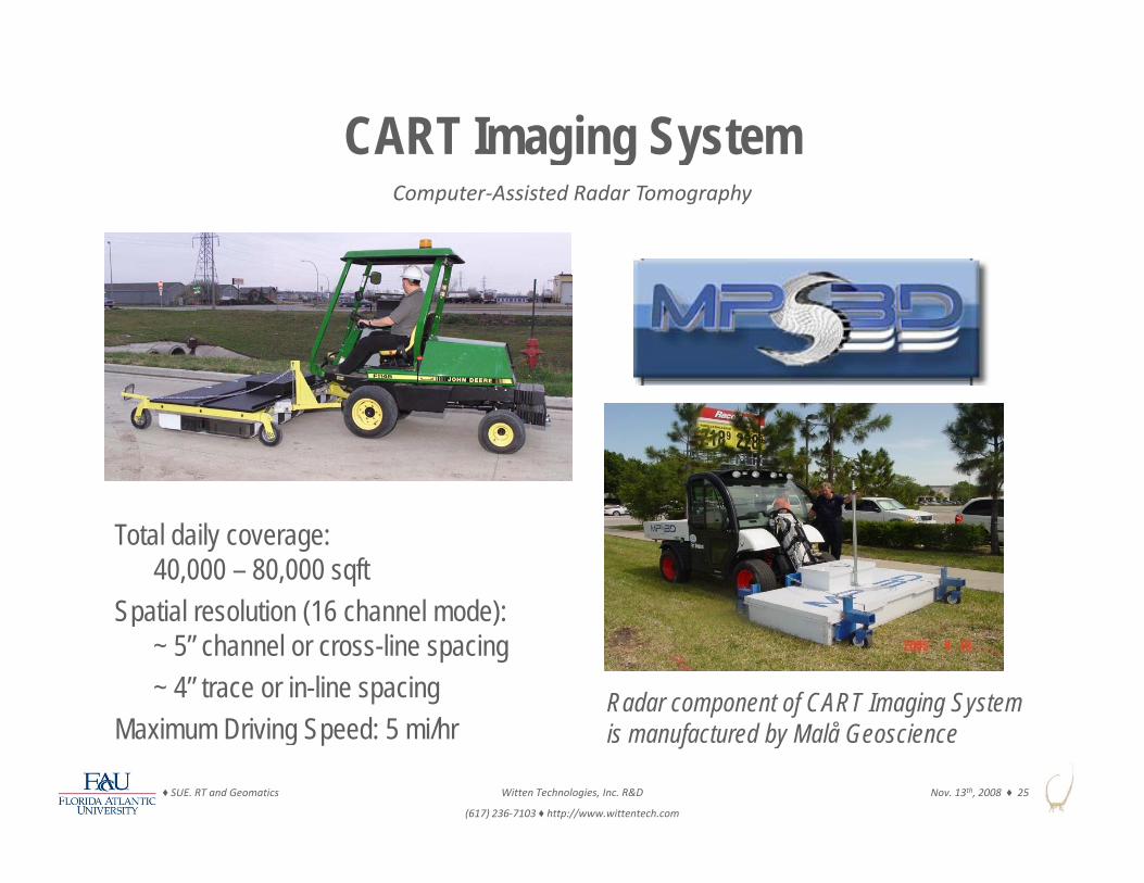
CART Imaging Systemg g yComputer‐Assisted Radar Tomography
Total daily coverage:40,000 – 80,000 sqft
Spatial resolution (16 channel mode): Spatial resolution (16 channel mode): ~ 5” channel or cross-line spacing~ 4” trace or in-line spacing
M i D i i S d 5 i/hRadar component of CART Imaging System
♦ SUE. RT and Geomatics Witten Technologies, Inc. R&D
(617) 236‐7103 ♦ http://www.wittentech.com
Nov. 13th, 2008 ♦ 25
Maximum Driving Speed: 5 mi/hr is manufactured by Malå Geoscience

CART Schematic
400 and 200 MHz antennas
♦ SUE. RT and Geomatics Witten Technologies, Inc. R&D
(617) 236‐7103 ♦ http://www.wittentech.com
Nov. 13th, 2008 ♦ 26

Operational Specifications in Words
• Depth of penetration is 4 to 6 ft in most sandy-clay soils (8 t 12 ft i d il ) it ifi ti(8 to 12 ft in sandy soils), very site specific, conservative
• Depth accuracy is about 5% (i.e., ± 3 in. over 5 ft)• Horizontal accuracy is about 1% from mapped surface
features such as manhole covers or curb linesR l ti f b f bj t i b t 3 t 4 i• Resolution of subsurface objects is about 3 to 4 in.– Objects as small as 1-in. can be seen at shallow depths– Resolution degrades with depth at rate of about 1 in/ft
• Typically certified to ± 6 in. in all 3 coordinates
♦ SUE. RT and Geomatics Witten Technologies, Inc. R&D
(617) 236‐7103 ♦ http://www.wittentech.com
Nov. 13th, 2008 ♦ 27

Positioning System I – Robotic Laser
• Precise geometry control provided by a self-tracking laser theodolite(robotic total station) locking on to a 360 degree prism(robotic total station) locking on to a 360 degree prism
• 3D accuracy of ±[1 ppm + 1 mm]; for example, ±2 mm in 1 km• Range of 2 km• Range of 2 km• Self-tracking, accurate
reading every 6 sprism
(faster ones available)• Standard technology for
construction surveyingconstruction surveying• Survey-grade,
can be certified by laser theodolite
♦ SUE. RT and Geomatics Witten Technologies, Inc. R&D
(617) 236‐7103 ♦ http://www.wittentech.com
Nov. 13th, 2008 ♦ 28
professional surveyorManufactured by Geodimeter (now Trimble)

Positioning System II - GPS
• Precise geometry control provided by RTK GPS system consisting of by RTK GPS system consisting of base station and rover
• Accurate reading every secondg y• 7.2 km/h (2 m/s) recommended
speed (one data point every 2 m)S ifi d A ith ffi i t • Specified Accuracy with sufficient Satellite coverage:– Horizontal: 10 mm + 1 ppmpp– Vertical: 15 mm + 1 ppm
• Survey-grade, can be certified by professional surveyor♦ SUE. RT and Geomatics Witten Technologies, Inc. R&D
(617) 236‐7103 ♦ http://www.wittentech.com
Nov. 13th, 2008 ♦ 29
professional surveyorManufactured by TOPCON (Hiper+ gr-2100)

Processing, Integration, Visualization
• The radar data are processed into geo-referenced seamless 3D radar imagesimages
• Those are interpreted for pipes• With the help of complementaryWith the help of complementary
information gathered with traditional SUE methods theutility types were identifiedutility types were identified
• The clients receive certified CADmaps in plan and profile showingp p p gthe 3D location of each pipecolored coded by utility
♦ SUE. RT and Geomatics Witten Technologies, Inc. R&D
(617) 236‐7103 ♦ http://www.wittentech.com
Nov. 13th, 2008 ♦ 30
• Autodesk, Microstation or ArcGIS

Please wait for example mapsp p
03_2006_Laura_St_Jak_JEA_Phz1.pdf
♦ SUE. RT and Geomatics Witten Technologies, Inc. R&D
(617) 236‐7103 ♦ http://www.wittentech.com
Nov. 13th, 2008 ♦ 31

Corrected CAD Maps
telephone duct banksoff by ten feet of more
lines not presenton original map
10 ft water line offb l f t
W
by several feet
Colored lines show utility locations according to available maps.
Black lines show actual locations (of selected utilities) determined
♦ SUE. RT and Geomatics Witten Technologies, Inc. R&D
(617) 236‐7103 ♦ http://www.wittentech.com
Nov. 13th, 2008 ♦ 32Church St
Black lines show actual locations (of selected utilities) determined by radar tomography.

Radar Tomography (RT)g p y ( )
Case Histories
♦ SUE. RT and Geomatics Witten Technologies, Inc. R&D
(617) 236‐7103 ♦ http://www.wittentech.com
Nov. 13th, 2008 ♦ 33

Radar Tomography (RT)
Example from theLower Manhattan Radar Projectj
♦ SUE. RT and Geomatics Witten Technologies, Inc. R&D
(617) 236‐7103 ♦ http://www.wittentech.com
Nov. 13th, 2008 ♦ 34

CART Surveys Near WTC
West St.Survey Area
♦ SUE. RT and Geomatics Witten Technologies, Inc. R&D
(617) 236‐7103 ♦ http://www.wittentech.com
Nov. 13th, 2008 ♦ 35
Areas surveyed in August 2001Areas surveyed from December 2001 – February 8th 2002

Lower Manhattan Radar ProjectLower Manhattan Radar ProjectHelp in planning reconstruction of the utility network of Lower ManhattanHelp in planning reconstruction of the utility network of Lower Manhattan
view north along West St view northeast corner of West and Liberty
♦ SUE. RT and Geomatics Witten Technologies, Inc. R&D
(617) 236‐7103 ♦ http://www.wittentech.com
Nov. 13th, 2008 ♦ 36
view north along West St view northeast corner of West and Liberty

20 ft
roadbed joints
s rface feat res
damaged zonewash outs?
RADAR IMAGE
surface featuresmanhole and valve covers
♦ SUE. RT and Geomatics Witten Technologies, Inc. R&D
(617) 236‐7103 ♦ http://www.wittentech.com
Nov. 13th, 2008 ♦ 37
RADAR IMAGE2 inches below street level

d h d f db d j i t
20 ft
radar shadow of roadbed joints
A
tops of service boxes
RADAR IMAGE
♦ SUE. RT and Geomatics Witten Technologies, Inc. R&D
(617) 236‐7103 ♦ http://www.wittentech.com
Nov. 13th, 2008 ♦ 38
RADAR IMAGE12 inches below street level
A

fradar shadow of roadbed joints
20 ft
gas
electric
RADAR IMAGE
♦ SUE. RT and Geomatics Witten Technologies, Inc. R&D
(617) 236‐7103 ♦ http://www.wittentech.com
Nov. 13th, 2008 ♦ 39
RADAR IMAGE24 inches below street level

20 ft
water
RADAR IMAGE
♦ SUE. RT and Geomatics Witten Technologies, Inc. R&D
(617) 236‐7103 ♦ http://www.wittentech.com
Nov. 13th, 2008 ♦ 40
RADAR IMAGE42 inches below street level

Please wait for movie to start
♦ SUE. RT and Geomatics Witten Technologies, Inc. R&D
(617) 236‐7103 ♦ http://www.wittentech.com
Nov. 13th, 2008 ♦ 41

RT – GIS Overview West Street
New York CityNew York City Orthophoto basemap -State Plane (NAD 83) f t
♦ SUE. RT and Geomatics Witten Technologies, Inc. R&D
(617) 236‐7103 ♦ http://www.wittentech.com
Nov. 13th, 2008 ♦ 42
(NAD 83) feet

♦ SUE. RT and Geomatics Witten Technologies, Inc. R&D
(617) 236‐7103 ♦ http://www.wittentech.com
Nov. 13th, 2008 ♦ 43

Radar Tomography (RT)
Case HistoryNYC, Cathedral Parkway ProjectNYC, Cathedral Parkway Project
♦ SUE. RT and Geomatics Witten Technologies, Inc. R&D
(617) 236‐7103 ♦ http://www.wittentech.com
Nov. 13th, 2008 ♦ 44

Cathedral Parkway Project“C t ti I t f ”“Construction Interference”
Determine if installation of footings for a new walkway along Central Park would require relocation of a high power feeder line
♦ SUE. RT and Geomatics Witten Technologies, Inc. R&D
(617) 236‐7103 ♦ http://www.wittentech.com
Nov. 13th, 2008 ♦ 45

♦ SUE. RT and Geomatics Witten Technologies, Inc. R&D
(617) 236‐7103 ♦ http://www.wittentech.com
Nov. 13th, 2008 ♦ 46

Contin o s ( i ) i i t t iview #1 east Continuous coverage (mapping) is important in projects that involve long section of utility lines
along walkway
view #2 northeast
DOUGLAS CIRCLE
#1
#2 Views of oil-o-static (138kV) lines under Cathedral Parkway near Douglas Circle
♦ SUE. RT and Geomatics Witten Technologies, Inc. R&D
(617) 236‐7103 ♦ http://www.wittentech.com
Nov. 13th, 2008 ♦ 47
FRAWLEY CIRCLE

Line pair is normally at 36 inches depth except for a short section where it rises to 24 inches (below grade)
♦ SUE. RT and Geomatics Witten Technologies, Inc. R&D
(617) 236‐7103 ♦ http://www.wittentech.com
Nov. 13th, 2008 ♦ 48
Map view of lines – color indicates depth

Cathedral Parkway
• Mapped ~2000 ft of high-voltage electrical feeder lines over entire l th f l d t tilength of planned construction
• Cost of $15k (30 000 sq ft at $0.50/sq ft) recovered in fewer test pits needed to verify that construction plan would not affect the linesneeded to verify that construction plan would not affect the lines– Number of test pits reduced from 20 (or more) to 5– Cost of a test pit in NYC is about $800 to $3000Cost of a test pit in NYC is about $800 to $3000
• “Cost Leverage”: Reduced risk of having to relocate the lines (a cost of $1 to $3 million) if original maps were inaccurate
♦ SUE. RT and Geomatics Witten Technologies, Inc. R&D
(617) 236‐7103 ♦ http://www.wittentech.com
Nov. 13th, 2008 ♦ 49

Electromagnetic Induction Arrayg y
Concepts
♦ SUE. RT and Geomatics Witten Technologies, Inc. R&D
(617) 236‐7103 ♦ http://www.wittentech.com
Nov. 13th, 2008 ♦ 50

Other Transaction Agreement #DTRS56-02-T-0005Digital Mapping of Buried Pipelines with a Dual-Array Systemg pp g p y y
R&D Project funded byWitten Technologies
C lid t d Edi C f N Y kConsolidated Edison Company of New YorkU.S. Department of Transportation Research and Special Projects Administration
With technical contributions from EMI (a division of Schlumberger)EMI (a division of Schlumberger)
Regional Water Authority of South Central ConnecticutSeknion
♦ SUE. RT and Geomatics Witten Technologies, Inc. R&D
(617) 236‐7103 ♦ http://www.wittentech.com
Nov. 13th, 2008 ♦ 51
October 2002 – December 2004

Mobile platform for urban mapping
♦ SUE. RT and Geomatics Witten Technologies, Inc. R&D
(617) 236‐7103 ♦ http://www.wittentech.com
Nov. 13th, 2008 ♦ 52

Arrayed Induction Receivers (AIR) System
MethodologyMethodologyElectromagnetic Induction Array
Accurate Utility MapsAccurate Utility Maps
ElectromagneticField Map
♦ SUE. RT and Geomatics Witten Technologies, Inc. R&D
(617) 236‐7103 ♦ http://www.wittentech.com
Nov. 13th, 2008 ♦ 53
Field Map

Electromagnetic Induction Arrayg y
Systems and Methodology
♦ SUE. RT and Geomatics Witten Technologies, Inc. R&D
(617) 236‐7103 ♦ http://www.wittentech.com
Nov. 13th, 2008 ♦ 54

Arrayed Induction Receiver (AIR) System• Array of 16 broadband vector
magnetic field sensors (induction coils)
• Broadband frequency response– Flat from 1 to 80 kHz
• Low noise level– 0.0005 nT @ 1 kHz– 0.0001 nT @ 10 kHz@
• Small package– 15 cm3, about 3 kg
• Built by EMI (Schlumberger)Built by EMI (Schlumberger)• Simultaneous data acquisition of
all 48 channels
♦ SUE. RT and Geomatics Witten Technologies, Inc. R&D
(617) 236‐7103 ♦ http://www.wittentech.com
Nov. 13th, 2008 ♦ 55

Survey-grade Positioning System
PRISM
BASE STATION
• System uses laser theodolite (robotic total station) for survey-grade positioning– 3D accuracy of ±[1 ppm + 1 mm]; for example, ±2 mm in 1 km
Range of 2 km– Range of 2 km– Self-tracking of 360 deg. prism, accurate reading every 6 s– Standard technology for construction surveying– Map surface features for local reference map
• Alternatively use survey grade GPS
♦ SUE. RT and Geomatics Witten Technologies, Inc. R&D
(617) 236‐7103 ♦ http://www.wittentech.com
Nov. 13th, 2008 ♦ 56
• Alternatively use survey-grade GPS

EM Source Options
Current injection (“clamp-on”)• Current injected directly onto pipe by galvanic Current injected directly onto pipe by galvanic
leads or toroidal clamp• Frequencies from 500 Hz to 85 kHz
Remote induction (“on-board”)• Three orthogonal coils of 0.7 m dia. • Moment of 5 at 1 kHz • Frequencies from 500 Hz to 50 kHz• Reference signal for phase detectionReference signal for phase detection
Existing signals
♦ SUE. RT and Geomatics Witten Technologies, Inc. R&D
(617) 236‐7103 ♦ http://www.wittentech.com
Nov. 13th, 2008 ♦ 57
• 60 Hz signals on power lines

Electromagnetic Induction Arrayg y
Case Histories
♦ SUE. RT and Geomatics Witten Technologies, Inc. R&D
(617) 236‐7103 ♦ http://www.wittentech.com
Nov. 13th, 2008 ♦ 58

83 kHz Lower Hx EM Field Data
‐ 0.66m
♦ SUE. RT and Geomatics Witten Technologies, Inc. R&D
(617) 236‐7103 ♦ http://www.wittentech.com
Nov. 13th, 2008 ♦ 59

39 kHz Total Horizontal EM Field
‐ 3.6m
‐ 3.3m
♦ SUE. RT and Geomatics Witten Technologies, Inc. R&D
(617) 236‐7103 ♦ http://www.wittentech.com
Nov. 13th, 2008 ♦ 60

8.9 kHz Total Horizontal EM Field
‐ 3.3m4 9m‐ 4.9m
♦ SUE. RT and Geomatics Witten Technologies, Inc. R&D
(617) 236‐7103 ♦ http://www.wittentech.com
Nov. 13th, 2008 ♦ 61

Dipping Power Line
♦ SUE. RT and Geomatics Witten Technologies, Inc. R&D
(617) 236‐7103 ♦ http://www.wittentech.com
Nov. 13th, 2008 ♦ 62
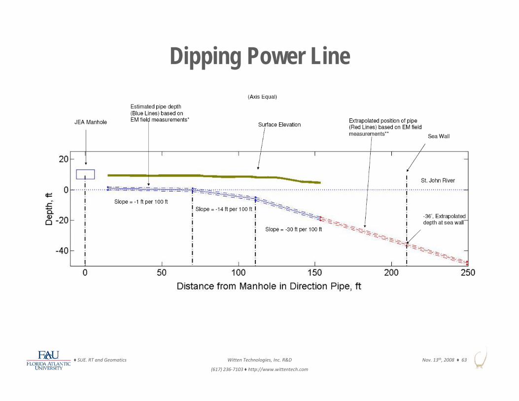
Dipping Power Line
♦ SUE. RT and Geomatics Witten Technologies, Inc. R&D
(617) 236‐7103 ♦ http://www.wittentech.com
Nov. 13th, 2008 ♦ 63

EM Complementing Radar
♦ SUE. RT and Geomatics Witten Technologies, Inc. R&D
(617) 236‐7103 ♦ http://www.wittentech.com
Nov. 13th, 2008 ♦ 64

Maps and Located Pipes in GIS
• EM Pipe Picks (gray lines),p (g y ),Radar Pipe Picks (color-codedby depth are superimposed on65 kHz horizontal magnetic field mapand 200 MHz Depth Slice at 30”and 200 MHz Depth Slice at 30
• Surface features (symbols) and the curbs in light gray
♦ SUE. RT and Geomatics Witten Technologies, Inc. R&D
(617) 236‐7103 ♦ http://www.wittentech.com
Nov. 13th, 2008 ♦ 65
• Map was composed in ARCGIS

Qualitative Pipe Picks Visualized in GIS
• Pipe Picks (gray lines) Pipe Picks (gray lines) are superimposed on 32 kHz horizontal
ti fi ld d t magnetic field data map and high-resolution aerial photoresolution aerial photo(courtesy of RWA)
• Map was composed in ARCGIS
♦ SUE. RT and Geomatics Witten Technologies, Inc. R&D
(617) 236‐7103 ♦ http://www.wittentech.com
Nov. 13th, 2008 ♦ 66
ARCGIS
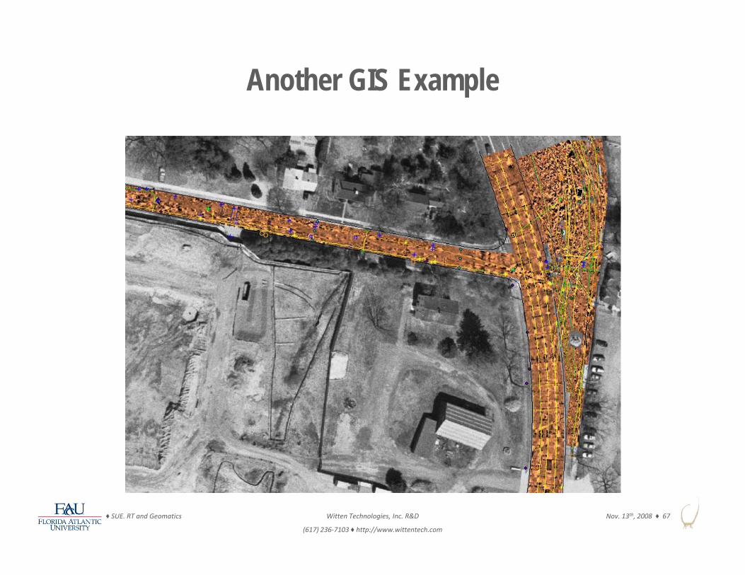
Another GIS Example
♦ SUE. RT and Geomatics Witten Technologies, Inc. R&D
(617) 236‐7103 ♦ http://www.wittentech.com
Nov. 13th, 2008 ♦ 67

Subsurface Utility Engineering (SUE)and the Impact of Geophysical Arraysand the Impact of Geophysical Arrays
♦ SUE. RT and Geomatics Witten Technologies, Inc. R&D
(617) 236‐7103 ♦ http://www.wittentech.com
Nov. 13th, 2008 ♦ 68

SUE and the Impact of Geophysical Arrays
• Suggestion to narrow gap between QL B and QL A using:A b d S f G h i l M th d– Array-based Surface Geophysical Methods
• As far as: QL AHigherAs far as:– Continuous
CoverageSUE Quality Levels
QL‐A
QL‐B
Higher
– Horizontal andVertical Position
– Cost versus Risk
COSTQL‐C
QL B
– Reusable geo-referenced digital data
QL‐D
Lower i h
♦ SUE. RT and Geomatics Witten Technologies, Inc. R&D
(617) 236‐7103 ♦ http://www.wittentech.com
Nov. 13th, 2008 ♦ 69
digital data RISKLower Higher
SUE and the Impact of Geophysical Arrays
• SUE (QL D, QL C, and QL B) combined with geophysical array technologies (especially RT) have the following advantages:technologies (especially RT) have the following advantages:– Horizontal and Vertical Position of Utilities
• typically certified to within 6 inches by WTI professional land surveyor– Provide continuous coverage throughout area of interestProvide continuous coverage throughout area of interest– Cost less than exposure (QL A), more than QL B– Risk lower than QL B, almost QL A
Reusable geo referenced digital data improving project design– Reusable geo-referenced digital data improving project design– Better-informed more efficient Design– Reduces number of exposures (e.g. can guide vacuum excavation)
Construction 14% cost reduction $4 62/$1 ROI*– Construction – 14% cost reduction, $4.62/$1 ROI*• Reduced conflict = fewer change orders• Reduced damage = increased safety• Faster completion = reduced public nuisance• Reduced risk = lower bids
♦ SUE. RT and Geomatics Witten Technologies, Inc. R&D
(617) 236‐7103 ♦ http://www.wittentech.com
Nov. 13th, 2008 ♦ 70
• Reduced risk = lower bids

Taking advantage of these new technologies'
• Professional Surveyors certifying resultsSt SUE/”B t P ti ” d t (i diti f it)• Stronger SUE/”Best Practice” mandates (i.e. condition of permit)
• ROW owners make Project Owners bear the cost of ROW entry• Accurate Information AT THE BID: “squeeze the risk”• Accurate Information AT THE BID: squeeze the risk• FDOT:
♦ SUE. RT and Geomatics Witten Technologies, Inc. R&D
(617) 236‐7103 ♦ http://www.wittentech.com
Nov. 13th, 2008 ♦ 71

S U M M A R Y 1
• Array-based geophysical systems are changing SUEASCE 38 02 itt l ki i t i i t id li– ASCE 38-02 committee looking into revising current guidelines
– FDOT in final step of adopting RT as one of the best practices to be used for certain larger projects
• Combination of SUE, RT, QL D, QL C, QL B and reduced use of exposures (limited QL A) may proof to be best way to negotiate cost and riskto negotiate cost and risk
• Recommend to:– learn and teach about these emerging technologies– learn and teach about these emerging technologies– test and use them in projects for value and cost savings
throughout overall project
♦ SUE. RT and Geomatics Witten Technologies, Inc. R&D
(617) 236‐7103 ♦ http://www.wittentech.com
Nov. 13th, 2008 ♦ 72

S U M M A R Y 2
• Commercial Radar Tomography (RT) Services using the CART Imaging System are offered since early 2001
• Deliverables include CAD Microstation or GIS subsurface utility • Deliverables include CAD, Microstation, or GIS subsurface utility maps in 3D located with RT
• Surveyed several Million of square-feet over the past 7 years
• Electromagnetic Induction Array Prototype available for special project to locate deeper conductive utilities
♦ SUE. RT and Geomatics Witten Technologies, Inc. R&D
(617) 236‐7103 ♦ http://www.wittentech.com
Nov. 13th, 2008 ♦ 73
project to locate deeper conductive utilities

WITTEN TECHNOLOGIES, INC.Research & Development
35 M df d St t S it 30635 Medford Street, Suite 306Somerville, MA 02143
www.wittentech.com ● +1 617 236 7103 ● [email protected]
♦ SUE. RT and Geomatics Witten Technologies, Inc. R&D
(617) 236‐7103 ♦ http://www.wittentech.com
Nov. 13th, 2008 ♦ 74
© WITTEN TECHNOLOGIES, INC. 2008. All rights reserved.