collapsible cores expandable cavities - dahanan · 2016-05-27 · collapsible cores, e xpandable...
TRANSCRIPT
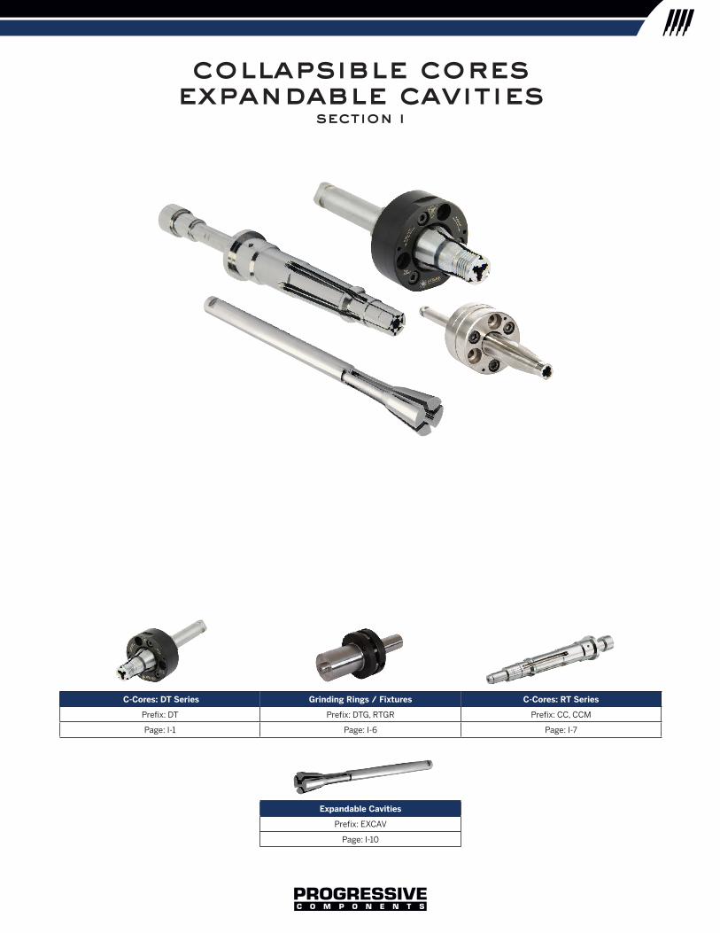
collapsible coresexpandable cavities
section i
C-Cores: DT Series Grinding Rings / Fixtures C-Cores: RT Series
Prefix: DT Prefix: DTG, RTGR Prefix: CC, CCM
Page: I-1 Page: I-6 Page: I-7
Expandable Cavities
Prefix: EXCAV
Page: I-10
IC
OL
LA
PS
IBL
E C
OR
ES
E
XP
AN
DA
BL
E C
AV
ITIE
S
V11-Tab-with-TAB.indd 9 4/4/2016 9:39:14 AM

I-1
CollapseStroke
EjectionStroke
CollapseStroke
EjectionStroke
CollapseStroke
EjectionStroke
collapsible cores
CollapseStroke
EjectionStroke
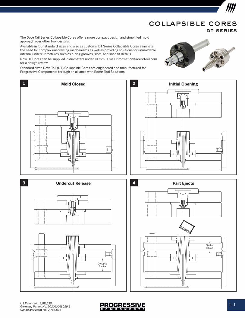
Mold Closed
Undercut Release
Initial Opening
Part Ejects
1 2
US Patent No. 9,011,138Germany Patent No. 202010018029.6 Canadian Patent No. 2,764,631
The Dove Tail Series Collapsible Cores offer a more compact design and simplified mold approach over other tool designs.
Available in four standard sizes and also as customs, DT Series Collapsible Cores eliminate the need for complex unscrewing mechanisms as well as providing solutions for unmoldable internal undercut features such as o-ring grooves, slots, and snap fit details.
Now DT Cores can be supplied in diameters under 10 mm. Email [email protected] for a design review.
Standard sized Dove Tail (DT) Collapsible Cores are engineered and manufactured for Progressive Components through an alliance with Roehr Tool Solutions.
3 4
dt series
collapsible cores, Expandable cavities
I-2
collapsible cores dt series
C
CD
D
BCT (3)
MLCT
S
SLL
B BD
BH
SD
QS2
GD
QW
QLQS16
Shaft Length (SL)
+.01+.03
Groove Diameter
±.05
6M4 x 10 SHCS
4 RLocation of plate groove
determined by mold design
60˚ grinding centerprovided on both ends.(Grind to suit.)
Flats forin-press
servicing
120˚(Typ.)
10˚
Stroke
Shaft Diameter
(SD)
Shaft Diameter (SD)Flats are tangent to GD
catalognumber
dMaximum
Outer Diameter
bMinimum
Inner Diameter+3°/Side
mlMaximum Molding Length
cMaximum Collapse
cdCarrier
Diameter+0.00- 0.05
ctCarrier
Assembly Thickness
± 0.05
lCore
Length+0.1- 0.0
slShaft
Length
sdShaft
Diameter+0.00- 0.02
bdCooling
HoleDiameter
bhDistance
to CoolingHole
bcMounting
Screw Bolt
Circle
tMounting
Screws
sMaximum Collapse Stroke
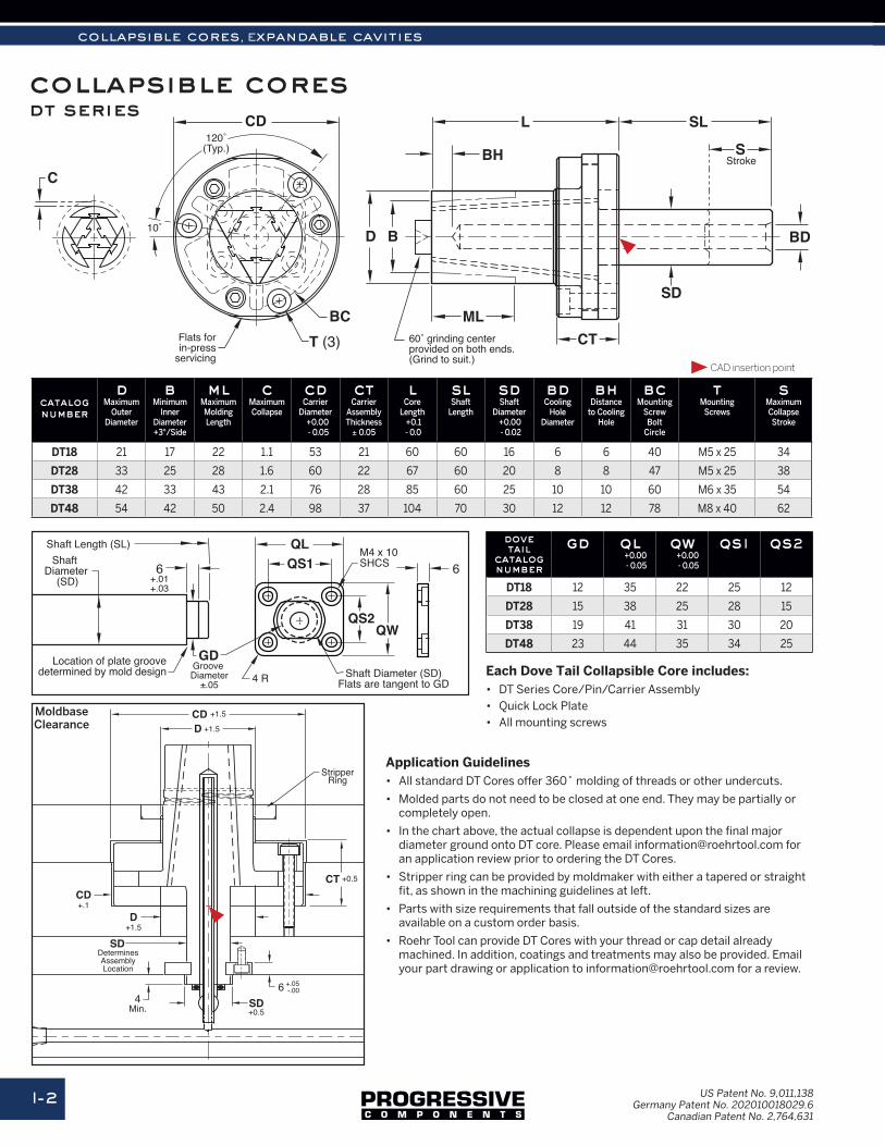
DT18 21 17 22 1.1 53 21 60 60 16 6 6 40 M5 x 25 34
DT28 33 25 28 1.6 60 22 67 60 20 8 8 47 M5 x 25 38
DT38 42 33 43 2.1 76 28 85 60 25 10 10 60 M6 x 35 54
DT48 54 42 50 2.4 98 37 104 70 30 12 12 78 M8 x 40 62
dove tail
catalognumber
gd ql+0.00- 0.05
qw+0.00- 0.05
qs1 qs2
DT18 12 35 22 25 12
DT28 15 38 25 28 15
DT38 19 41 31 30 20
DT48 23 44 35 34 25
Application Guidelines• All standard DT Cores offer 360˚ molding of threads or other undercuts.
• Molded parts do not need to be closed at one end. They may be partially or completely open.
• In the chart above, the actual collapse is dependent upon the final major diameter ground onto DT core. Please email [email protected] for an application review prior to ordering the DT Cores.
• Stripper ring can be provided by moldmaker with either a tapered or straight fit, as shown in the machining guidelines at left.
• Parts with size requirements that fall outside of the standard sizes are available on a custom order basis.
• Roehr Tool can provide DT Cores with your thread or cap detail already machined. In addition, coatings and treatments may also be provided. Email your part drawing or application to [email protected] for a review.
Each Dove Tail Collapsible Core includes:• DT Series Core/Pin/Carrier Assembly• Quick Lock Plate• All mounting screws
CAD insertion point
D +1.5
CT +0.5
DeterminesAssemblyLocation
D+1.5
64
Min.
StripperRing
CD+.1
SD
SD+0.5
+.05-.00
CD +1.5MoldbaseClearance
US Patent No. 9,011,138 Germany Patent No. 202010018029.6
Canadian Patent No. 2,764,631
I-3
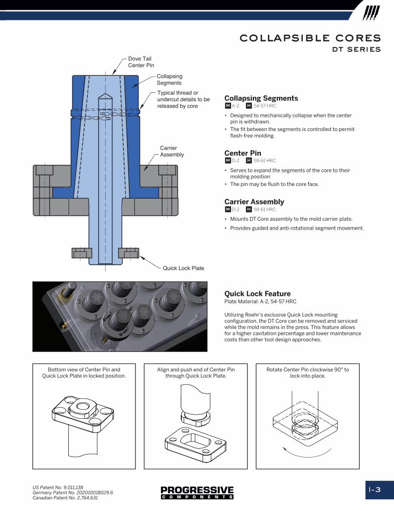
collapsible coresDove TailCenter Pin
Typical thread orundercut details to bereleased by core
CollapsingSegments
CarrierAssembly
Quick Lock Plate
Align and push end of Center Pin through Quick Lock Plate.
Rotate Center Pin clockwise 90° to lock into place.
Bottom view of Center Pin and Quick Lock Plate in locked position.
Quick Lock FeaturePlate Material: A-2, 54-57 HRC
Utilizing Roehr’s exclusive Quick Lock mounting configuration, the DT Core can be removed and serviced while the mold remains in the press. This feature allows for a higher cavitation percentage and lower maintenance costs than other tool design approaches.
Collapsing Segments
• Designed to mechanically collapse when the center pin is withdrawn.
• The fit between the segments is controlled to permit flash-free molding.
Center Pin
• Serves to expand the segments of the core to their molding position
• The pin may be flush to the core face.
Carrier Assembly
• Mounts DT Core assembly to the mold carrier plate.
• Provides guided and anti-rotational segment movement.
m D-2 h 59-61 HRC
m A-2 h 54-57 HRC
m D-2 h 59-61 HRC
US Patent No. 9,011,138Germany Patent No. 202010018029.6 Canadian Patent No. 2,764,631
dt series
collapsible cores, Expandable cavities
I-4
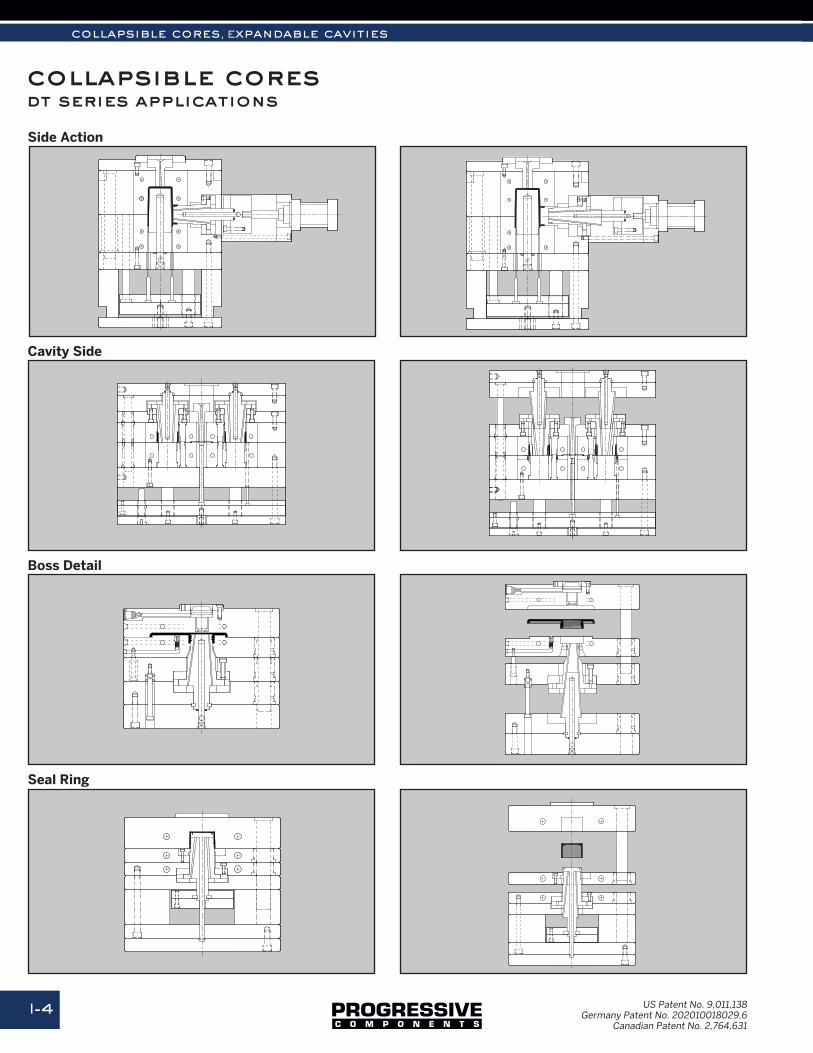
collapsible cores dt series applications
Side Action
Boss Detail
Cavity Side
Seal Ring
US Patent No. 9,011,138Germany Patent No. 202010018029.6
Canadian Patent No. 2,764,631
I-5
collapsible cores
catalognumber
mdMaximum Molding Diameter
idMinimum Molding Diameter
mlMaximum Molding Length
ucMaximum Undercut
cdCarrier
AssemblyDiameter
cbCarrier
AssemblyBody
ctCarrier
AssemblyThickness
lLength
slShaft
Length
sdShaft
Diameter
sMaximum CollapseStroke
bdCooling
HoleDiameter
bhCooling
HoleHeight
bcMounting
Bolt Circle
tMounting
Bolt (3)
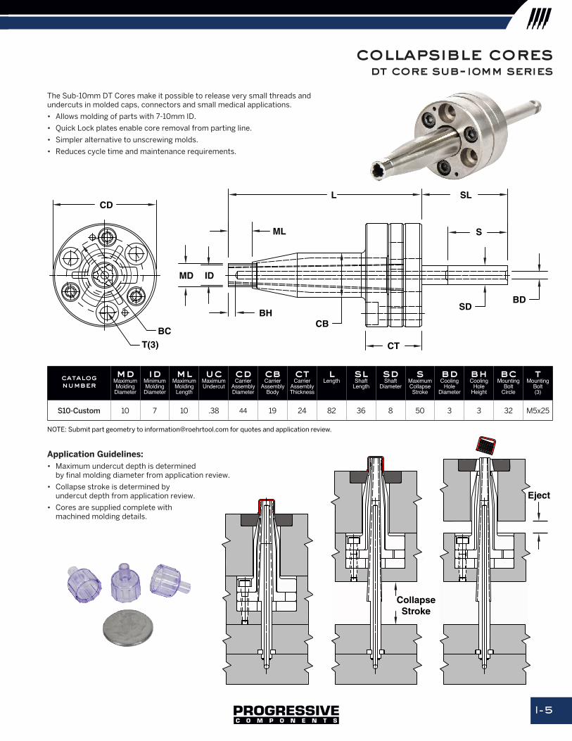
S10-Custom 10 7 10 .38 44 19 24 82 36 8 50 3 3 32 M5x25
Application Guidelines:• Maximum undercut depth is determined
by final molding diameter from application review.
• Collapse stroke is determined by undercut depth from application review.
• Cores are supplied complete with machined molding details.
Eject
CollapseStroke
The Sub-10mm DT Cores make it possible to release very small threads and undercuts in molded caps, connectors and small medical applications.
• Allows molding of parts with 7-10mm ID.
• Quick Lock plates enable core removal from parting line.
• Simpler alternative to unscrewing molds.
• Reduces cycle time and maintenance requirements.
NOTE: Submit part geometry to [email protected] for quotes and application review.
CD
ML
BH
MD
L SL
SDBD
CT
ID
CB
S
BCT(3)
dt core sub-10mm series
collapsible cores, Expandable cavities
I-6
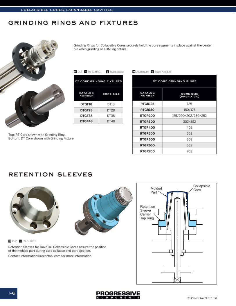
grinding rings and fixtures
Grinding Rings for Collapsible Cores securely hold the core segments in place against the center pin when grinding or EDM’ing details.
Retention Sleeves for DoveTail Collapsible Cores assure the position of the molded part during core collapse and part ejection.
Contact [email protected] for more information.
dt core grinding fixtures
catalognumber core size
DTGF18 DT18
DTGF28 DT28
DTGF38 DT38
DTGF48 DT48
rt core grinding rings
catalognumber core size
(prefix cc)
RTGR125 125
RTGR150 150/175
RTGR200 175/200/202/250/252
RTGR300 302/352
RTGR400 402
RTGR500 502
RTGR600 602
RTGR650 652
RTGR700 702
CollapsibleCoreMolded
Part
RetentionSleeveCarrierTop Ring
retention sleeves
mm Aluminum s Black Anodizes Black OxideD-2 h 59-61 HRC
m D-2 h 59-61 HRC
US Patent No. 9,011,138
Top: RT Core shown with Grinding Ring.Bottom: DT Core shown with Grinding Fixture.
I-7US Patent No. 4,919,608Canadian Patent No. 1,330,479
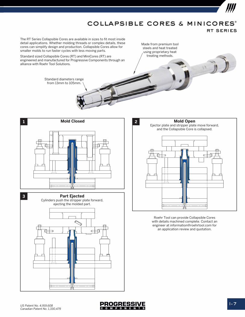
Roehr Tool can provide Collapsible Cores with details machined complete. Contact anengineer at [email protected] for
an application review and quotation.
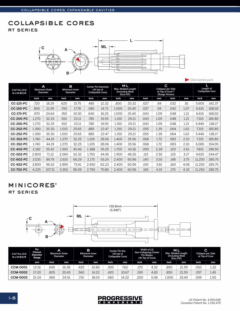
The RT Series Collapsible Cores are available in sizes to fit most inside detail applications. Whether molding threads or complex details, these cores can simplify design and production. Collapsible Cores allow for smaller molds to run faster cycles with less moving parts.
Standard sized Collapsible Cores (RT) and MiniCores (RT) are engineered and manufactured for Progressive Components through an alliance with Roehr Tool Solutions.
Standard diameters range from 13mm to 105mm.
Made from premium tool steels and heat treated using proprietary heat
treating methods.
Mold Closed1
collapsible cores & minicores®
rt series
Mold OpenEjector plate and stripper plate move forward,
and the Collapsible Core is collapsed.
2
Part EjectedCylinders push the stripper plate forward,
ejecting the molded part.
3
collapsible cores, Expandable cavities
I-8
collapsible cores rt series
C
B
MLL
150.8mm(5.940”)
A
C
B
ML
L
A
C
B
A
catalognumber
aMaximum Outer
Diameter
bMinimum Inner
Diameter
Center Pin Diameter(At top of
Collapsible Core)
mlMax. Molded Length
(Including MoldShut-Off)
cCollapse per Sideat Top of Core**(Range Shown)
lLength of
Collapsible Core
Inch mm Inch mm Inch mm Inch mm Inch mm Inch mm Inch mm
CC-125-PC .720 18.29 .620 15.75 .485 12.32 .800 20.32 .027 .69 .032 .81 5.605 142.37
CC-150-PC .850 21.59 .700 17.78 .580 14.73 1.000 25.40 .037 .94 .042 1.07 6.615 168.02
CC-175-PC .970 24.64 .760 19.30 .640 16.25 1.000 25.40 .043 1.09 .048 1.21 6.615 168.02
CC-200-PC 1.270 32.25 .910 23.11 .785 19.93 1.150 29.21 .043 1.09 .048 1.21 7.315 185.80
CC-250-PC 1.270 32.25 .910 23.11 .785 19.93 1.150 29.21 .043 1.09 .048 1.21 5.440 138.17
CC-202-PC 1.390 35.30 1.010 25.65 .885 22.47 1.150 29.21 .055 1.39 .064 1.62 7.315 185.80
CC-252-PC 1.390 35.30 1.010 25.65 .885 22.47 1.150 29.21 .055 1.39 .064 1.62 5.440 138.17
CC-302-PC 1.740 44.19 1.270 32.25 1.105 28.06 1.400 35.56 .068 1.72 .083 2.10 7.315 185.80
CC-352-PC 1.740 44.19 1.270 32.25 1.105 28.06 1.400 35.56 .068 1.72 .083 2.10 6.065 154.05
CC-402-PC 2.182 55.42 1.593 40.46 1.388 35.25 1.700 43.18 .090 2.28 .103 2.61 7.815 198.50
CC-502-PC 2.800 71.12 2.060 52.32 1.750 44.45 1.900 48.26 .115 2.92 .125 3.17 9.625 244.47
CC-602-PC 3.535 89.78 2.610 66.29 2.175 55.24 2.400 60.96 .140 3.55 .148 3.75 11.250 285.75
CC-652-PC 3.800 96.52 2.890 73.41 2.450 62.23 2.400 60.96 .150 3.81 .160 4.06 11.250 285.75
CC-702-PC 4.225 107.31 3.350 85.09 2.790 70.86 2.400 60.96 .165 4.19 .170 4.32 11.250 285.75
catalognumber
For Closure
Diameter Range
aMaximum Outer
Diameter
bMinimum Inner
Diameter
Center Pin Dia.(At top of
Collapsible Core)
Width of (3) Non-Collapsing Center
Pin Blades(At Top of Core)
mlMax. Molded Length
(Including MoldShut-Off)
cCollapse per Side
at Top of Core
mm Inch mm Inch mm Inch mm Inch mm Inch mm Inch mm
CCM-0001 13-16 .645 16.38 .425 10.80 .300 7.62 .170 4.32 .850 21.59 .052 1.32
CCM-0002 17-20 .805 20.45 .560 14.22 .420 10.67 .190 4.83 .850 21.59 .057 1.45
CCM-0003 21-24 .965 24.51 .710 18.03 .560 14.22 .200 5.08 1.000 25.40 .059 1.50
C
B
MLL
150.8mm(5.940”)
A
C
B
ML
L
A
C
B
A
minicores®
rt series
CAD insertion point
US Patent No. 4,919,608Canadian Patent No. 1,330,479
I-9
collapsible cores & minicores®
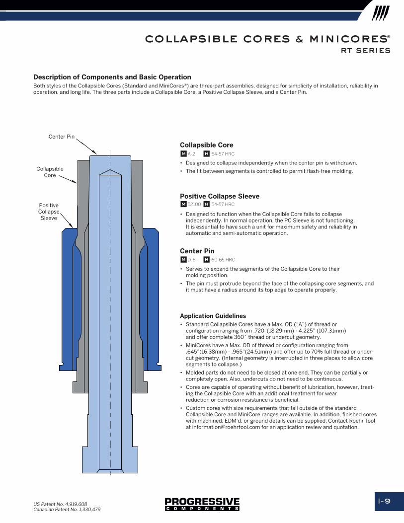
Description of Components and Basic OperationBoth styles of the Collapsible Cores (Standard and MiniCores®) are three-part assemblies, designed for simplicity of installation, reliability in operation, and long life. The three parts include a Collapsible Core, a Positive Collapse Sleeve, and a Center Pin.
Center Pin
CollapsibleCore
PositiveCollapseSleeve
Collapsible Core
• Designed to collapse independently when the center pin is withdrawn.
• The fit between segments is controlled to permit flash-free molding.
Positive Collapse Sleeve
• Designed to function when the Collapsible Core fails to collapse independently. In normal operation, the PC Sleeve is not functioning. It is essential to have such a unit for maximum safety and reliability in automatic and semi-automatic operation.
Center Pin
• Serves to expand the segments of the Collapsible Core to their molding position.
• The pin must protrude beyond the face of the collapsing core segments, and it must have a radius around its top edge to operate properly.
Application Guidelines• Standard Collapsible Cores have a Max. OD (“A”) of thread or
configuration ranging from .720”(18.29mm) - 4.225” (107.31mm) and offer complete 360˚ thread or undercut geometry.
• MiniCores have a Max. OD of thread or configuration ranging from .645”(16.38mm) - .965”(24.51mm) and offer up to 70% full thread or under-cut geometry. (Internal geometry is interrupted in three places to allow core segments to collapse.)
• Molded parts do not need to be closed at one end. They can be partially or completely open. Also, undercuts do not need to be continuous.
• Cores are capable of operating without benefit of lubrication, however, treat-ing the Collapsible Core with an additional treatment for wear reduction or corrosion resistance is beneficial.
• Custom cores with size requirements that fall outside of the standard Collapsible Core and MiniCore ranges are available. In addition, finished cores with machined, EDM’d, or ground details can be supplied. Contact Roehr Tool at [email protected] for an application review and quotation.
m A-2 h 54-57 HRC
m 52100 h 54-57 HRC
m D-6 h 60-65 HRC
US Patent No. 4,919,608Canadian Patent No. 1,330,479
rt series
collapsible cores, Expandable cavities
I-10
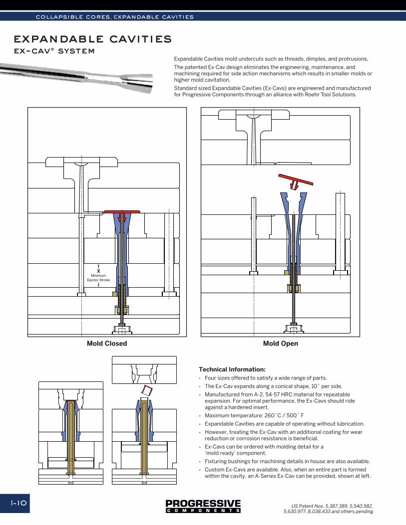
expandable cavitiesExpandable Cavities mold undercuts such as threads, dimples, and protrusions.
The patented Ex-Cav design eliminates the engineering, maintenance, and machining required for side action mechanisms which results in smaller molds or higher mold cavitation.
Standard sized Expandable Cavities (Ex-Cavs) are engineered and manufactured for Progressive Components through an alliance with Roehr Tool Solutions.
Technical Information:• Four sizes offered to satisfy a wide range of parts.
• The Ex-Cav expands along a conical shape, 10˚ per side.
• Manufactured from A-2, 54-57 HRC material for repeatable expansion. For optimal performance, the Ex-Cavs should ride against a hardened insert.
• Maximum temperature: 260˚C / 500˚ F
• Expandable Cavities are capable of operating without lubrication.
• However, treating the Ex-Cav with an additional coating for wear reduction or corrosion resistance is beneficial.
• Ex-Cavs can be ordered with molding detail for a ‘mold ready’ component.
• Fixturing bushings for machining details in house are also available.
• Custom Ex-Cavs are available. Also, when an entire part is formed within the cavity, an A-Series Ex-Cav can be provided, shown at left.
XMinimum
Ejector Stroke
XMinimum
Ejector Stroke
Mold Closed
US Patent Nos. 5,387,389, 5,540,582, 5,630,977, 8,038,433 and others pending
Mold Open
ex-cav® system
I-11
expandable cavities
mounting kits & machining specs
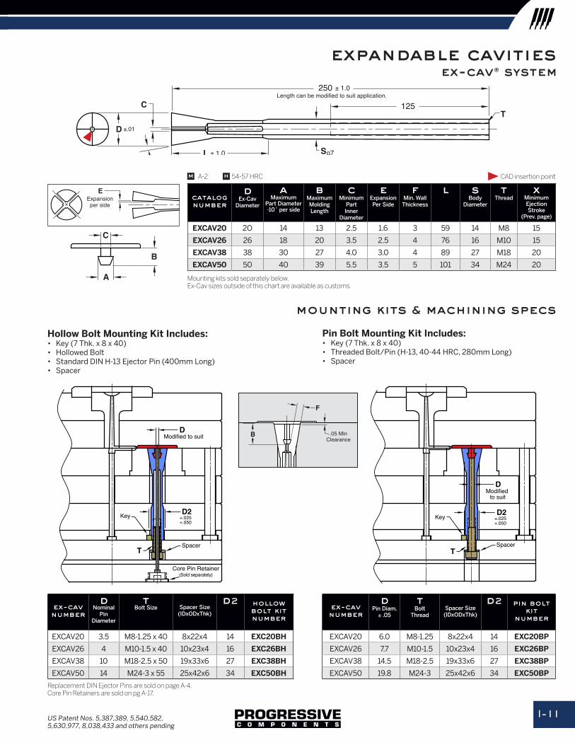
ex-cavnumber
dPin Diam.
± .05
tBolt
ThreadSpacer Size
(IDxODxThk)
d2 pin bolt kit
number
EXCAV20 6.0 M8-1.25 8x22x4 14 EXC20BP
EXCAV26 7.7 M10-1.5 10x23x4 16 EXC26BP
EXCAV38 14.5 M18-2.5 19x33x6 27 EXC38BP
EXCAV50 19.8 M24-3 25x42x6 34 EXC50BP
B
A
C
D
C
E
S
T125
10˚(Conical)
250 ± 1.0
g7
±.01
Length can be modified to suit application.
Expansionper side
L ± 1.0
B
A
C
D
C
E
S
T125
10˚(Conical)
250 ± 1.0
g7
±.01
Length can be modified to suit application.
Expansionper side
L ± 1.0
D
D2
T
Modified to suit
+.025+.050
Key
Spacer
Core Pin Retainer(Sold separately)
D2
D
T
+.025+.050
Key
Spacer
Modified to suit
Hollow Bolt Mounting Kit Includes:• Key (7 Thk. x 8 x 40)• Hollowed Bolt• Standard DIN H-13 Ejector Pin (400mm Long)• Spacer
Pin Bolt Mounting Kit Includes:• Key (7 Thk. x 8 x 40)• Threaded Bolt/Pin (H-13, 40-44 HRC, 280mm Long)• Spacer
B
A
C
D
C
E
S
T125
10˚(Conical)
250 ± 1.0
g7
±.01
Length can be modified to suit application.
Expansionper side
L ± 1.0
Replacement DIN Ejector Pins are sold on page A-4. Core Pin Retainers are sold on pg A-17.
catalognumber
dEx-Cav
Diameter
aMaximum
Part Diameter-10˚ per side
bMaximumMolding Length
cMinimum
PartInner
Diameter
eExpansionPer Side
fMin. Wall
Thickness
l sBody
Diameter
tThread
xMinimumEjection Stroke
(Prev. page)
EXCAV20 2O 14 13 2.5 1.6 3 59 14 M8 15
EXCAV26 26 18 20 3.5 2.5 4 76 16 M10 15
EXCAV38 38 30 27 4.0 3.0 4 89 27 M18 20
EXCAV50 50 40 39 5.5 3.5 5 101 34 M24 20
Mounting kits sold separately below.Ex-Cav sizes outside of this chart are available as customs.
m hA-2 54-57 HRC
B
F
.05 MinClearance
ex-cavnumber
dNominal
Pin Diameter
tBolt Size Spacer Size
(IDxODxThk)
d2 hollow bolt kit number
EXCAV20 3.5 M8-1.25 x 40 8x22x4 14 EXC20BH
EXCAV26 4 M10-1.5 x 40 10x23x4 16 EXC26BH
EXCAV38 10 M18-2.5 x 50 19x33x6 27 EXC38BH
EXCAV50 14 M24-3 x 55 25x42x6 34 EXC50BH
CAD insertion point
US Patent Nos. 5,387,389, 5,540,582, 5,630,977, 8,038,433 and others pending
ex-cav® system