cold spray (cs) coatings for cr and ni plating replacement · most promising powder formulations....
TRANSCRIPT

.
Aaron Nardi, Victor ChampagneUS Army Research Laboratory
ASETS Defense MeetingAugust 2018
Cold Spray (CS) Coatings for Cr and Ni Plating Replacement

.
2
Basic Process is known – but the technology must be ‘enabled’to allow development of new materials/coatings.
“Materials by Design” Approach-Materials Science-Modeling-Hardware/Software ARL Cold Spray Center has led R&D and applications development since 2000’s
CS developed in Russia in mid 1980’s but has yet to realize potential Cr plating replacement material not developed to date

.Typical Cold Spray Equipment
3
Possible setups for either hand or robotic
application
Typical setup includes:• Cold Spray System• Robot• Spray hood or exhaust• Dust collector• Sound Enclosure• Gas source

.Solid State Metallic Bonding
• Materials compatibility enables increased bond strength• Compatible bond layers• Encapsulated powders
• Surface contamination requires higher surface expansion (strain) to achieve bonding
• High plastic strain of both surfaces improves bonding• Material jetting from interface can eliminate or further breakdown
surface contamination
4
Summary of comparisons
Material CompatibilityHigh Plastic Strain
High Strain Rate Jetting

.
Cold Sprayed Coatings for Cr and Ni Plating Replacement
5
Technology Focus Utilize the proven technology of Cold Spray deposition to produce coatings that can
substitute for Chrome and Nickel plating in OEM and repair applications
Research Objectives1.Identify the correct powder morphology and composition for hard coating CS deposition2.Select and/or develop the required powders 3.Optimize Cold Spray process parameters4.Develop nozzles/hardware to couple with CS parameters in enabling high wear and
impact coatings5.Perform materials characterization and requirements6.Identify potential hardware for demo/validation
Project Progress and Results Over 160 different spray trials have been performed on different powder formulations Several solutions exist for replacement of nickel plating using either helium or nitrogen
spray conditions Solutions have been identified for coatings with hardness in the range of 400 – 1300 HV The two solutions which have shown the most promise include a 400 HV moderate wear
resistant and highly impact resistant coating as well as a highly wear resistant and moderately impact resistant 700 HV coating
All solutions can achieve exceptional bond strength to even high hardness (55HRC) steel substrates

.
6
Bond-line
Hardness
Microstructure
Porosity
Wear
In-situ mechanical tests in SEM
Particle size distribution
Microstructure
Morphology
Hardness
Density
CS Process Conditions
• Pressure• Temperature • Accelerating gas
Environmental Regulations
Composition
Manufacturing process
Compatibility
Health Hazards
Impact Modeling: Actual copper CS deposit
-5
-4
-3
-2
-1
0
0
200
400
600
800
1000
1200
0.00 0.10 0.20 0.30 0.40
m/s
& d
egre
e K
nozzle axis, meters particle velocity particle temp nozzle exit gas velocity gas temp Upper Nozzle
CS : Relative Critical Velocity Ratio Calculations
CFD: Nozzle and Process Modeling
0 200 400 600 800 1000 1200 1400 1600 1800 2000
Fracti
onal
Parti
cle Co
unt
Velocity (m/s)
Particle Distribution Velocity | Predicted vs. Measured
Predicted | Particle velocity distributionMeasured | Mean velocity of distributionMeasured | Mean velocity distribution
Validation:Velocity calculations calibrated with Laser Doppler Velocimeter
Post-Processing Characterization
Powder / Material Characterization
Cold Spray Process
Powder / Material Selection
Analytical Tools
Holistic Approach to Coating Development
Spray Drying
Chemical Clad
Mechanical Clad
Cold Spray System Design
• Temperature capability
• Powder heating• Gun heating
N2
/ He
Nozzle Design• Conventional nozzles
with varying aspect ratios
• Specialty ID nozzles

.
The goal of this project is therefore to: a. Identify the appropriate types of soft and
hard phasesb. Identify the best configuration of these
phases within the powder particlec. Identify the appropriate particle sized. Design nozzles for achieving particle
velocity and temperature predicted to produce high quality coatings
e. Develop the spray process parameters required to consolidate designed material
What makes a high quality Cold Spray coating The Cold Spray process achieves particle bonding
through a process of high velocity impact and plastic deformation
Powders used in Cold Spray must contain a “soft” plastic phase in order to properly consolidate when the powder undergoes plastic deformation
To create hard coatings, a significant quantity of hard phase is required in the coating
For high toughness coatings less hard phase is required while inter-particle bonding is critical
7
Technical Approach
Materials by Design
Hard Phases
• Tungsten Carbide• Chrome Carbide• Iron Based Hard
powders
Soft Phases
• Nickel• Stainless Steel• Cobalt• Chrome• Tantalum• Niobium• Bronze• Copper-Nickel
Methods of Combination
Blending
High Energy Milling
Powder Plating
Small-Large Powder Granulation
Spray Drying / Agglomeration
Nozzle Design and Process Development
Mini-nozzle for tight spaces
High Temperature powder preheat
Fine and narrow PSD

.Most Promising Powder Formulations
8
Electrochemical Plating Mechanical CladdingSpray drying or agglomerated and sintered
Powder blending is by far the simplest and best solution for low to medium hardness deposits The exact ratio, PSD, chemistry, and morphology of hard to soft phases plays a critical role in bonding, hardness, and toughness of the deposits created
Achieving high hardness requires the combination of both hard and soft constituents into each powder particle

.
Mechanical Blend Spray Dried and SinteredCombined ProcessingSpray Dried + Coated
Most Promising Powder Formulations
9
Powder Blends have achieved approximately 375-450 HV hardness depositsModerate to high wear resistance with the best impact properties
Spray Dried or agglomerated and sintered powders have achieved the highest hardness ranging from 800 – 1300 HV depending on composition
Design optimized clad agglomerate powders show the best overall properties including higher DE, good toughness, and excellent wear performance

.
Summary of Materials Developed
10
Blended powders with moderate hardness and wear resistance as well as excellent toughness and impact resistance
Agglomerated and sintered powders with extremely high hardness and wear resistance
Specially designed agglomerated clad powders with the best mix of both high hardness and wear resistance with good impact resistance and toughness
Options including CrC, WC, and iron based hard phases Options including Co, Ni, and iron based soft phases
EH&S
WearImpact
Application Requirements
Powder Selection Process
Fatigue
Other
Selected Powder
WIP-C1WIP-C2WIP-W1WIP-F1
Wear and Impact Protection (WIP) series of powders

.
Chrome Plating WC-17Co
WIP-W1 WIP-C1
Coating Systems Evaluated for Wear
11

.
Cold Sprayed Materials
ASTM G133 Ball-on-flat Reciprocating Wear Testing
WIP-W1 WIP-C1
Coating Systems Evaluated for Wear
Wear Testing was performed at ORNL for AED-MED on Cold sprayed coatings produced from the powders developed under this SERDP effort
12

.
13
UTRC Al2O3 ball on flat reciprocating
Coating Systems Evaluated for Wear
WIP-C1 Cold Spray
Chrome plating
Wear through the plating
.
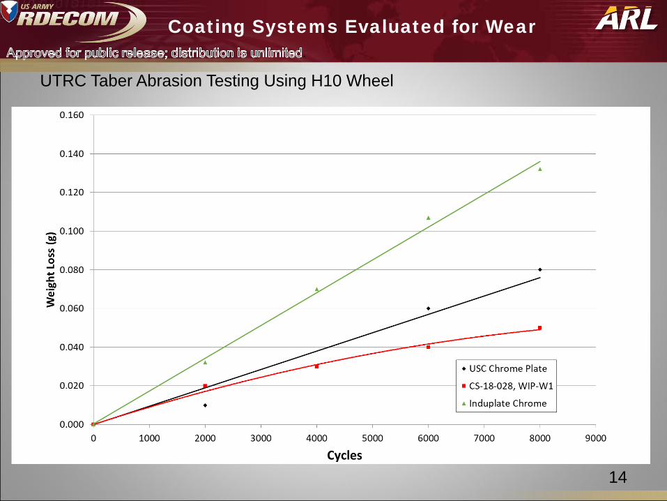
14
Coating Systems Evaluated for Wear
UTRC Taber Abrasion Testing Using H10 Wheel

.
15
WIP-C1 and WIP-C2 These deposits are being rolled out into several applications and have by far the most
robust set of data and spray conditions of all WIP materials Vendors have been set up to produce this material commercially for easier procurement Deposits have been demonstrated with both helium and nitrogen with good quality Deposits can be machined by milling, turning, or grinding
WIP-F1 This material is very similar to WIP-C1 and C2 but is completely iron based for
applications where EH&S concerns about nickel based deposits may be present More work needs to be done to characterize the properties, especially wear
performance, of this material Once further data is developed scale-up of this material to production quantities will
follow the process for WIP-C1 and C2
WIP-W1 This material has the greatest potential for direct chrome replacement in most
applications The data generated has shown excellent wear and Deposits must be ground, but can be ground with SiC or diamond All powders have been produced in a laboratory using production robust processes
Current State of Development with WIP Coatings
All coatings can be applied in line of site applications as well as in features as small as 1.8 - 2 inches

.
Thank you
Questions?
16

.
Semi-Empirical Study of Deposit Bonding
17
Hard particles tend to have smaller effective area due to
lack of deformation
Soft particles tend to flatten increasing their effective area
on the surface
Effective areaEffective area
The effect of blend ratios on bond strength has been correlated to particle size & density
Use the PSD, material density, and blend ratio to determine projected area of metal particles and hard phase particles

.
18
Based on experimental data generated the projected area of hard phase particles must be 4X the projected
area of metal particles to get high bond strength
Optimization of Blend Ratios to Achieve high Bond Strength
Density (g/cc) 6.971 Size (um) FractionProjected Area
(um 2̂)D10 Particle Size (um) 45 106 0.033 60097892D90 Particle Size (um) 106 100 0.049 95651299Blend Mass Percentage 90 94 0.072 149411816Particle Hardness (HV) 1000 88 0.115 254233955
82 0.148 351307529Total projected area in 1 gram of
blend 2671454758 76 0.164 42187924069 0.148 41306476063 0.115 35223250957 0.072 24501448251 0.049 18699735445 0.033 141563923
Density (g/cc) 8.9 Size (um) FractionProjected Area
(um 2̂)D10 Particle Size (um) 16 45 0.033 12320126D90 Particle Size (um) 45 42 0.049 19753171Blend Mass Percentage 10 39 0.072 31114604
Sprayed Particle Hardness (HV) 240 36 0.115 5345509333 0.148 74695376
Total projected area in 1 gram of blend 585776288 31 0.164 90886177
28 0.148 9039223025 0.115 7855950922 0.072 5594919719 0.049 4400045116 0.033 34650355
Overlap Area Ratio 4.56
Assumed PSDHard Particle
Assumed PSDSoft Particle
0.000
0.050
0.100
0.150
0.200
0 20 40 60 80 100 120
Phas
e Fr
actio
n
Particle Size
0.000
0.050
0.100
0.150
0.200
0 20 40 60 80 100 120
Phas
e Fr
actio
n
Particle Size
This applies directly to WIP-C1 buildup and bondcoat used for WC topcoats
Semi-Empirical Study of Deposit Bonding
Developed empirical model to predict blend requirements for optimized bonding
.
Powder Impact Modeling
19
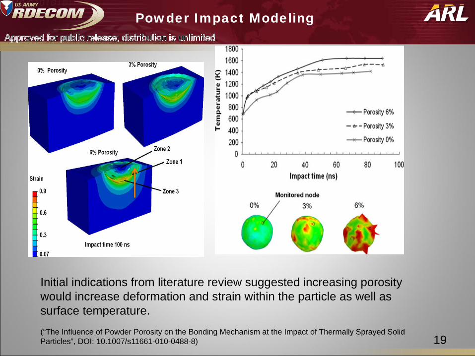
Initial indications from literature review suggested increasing porosity would increase deformation and strain within the particle as well as surface temperature. (“The Influence of Powder Porosity on the Bonding Mechanism at the Impact of Thermally Sprayed Solid Particles”, DOI: 10.1007/s11661-010-0488-8)
.
Powder Impact Modeling
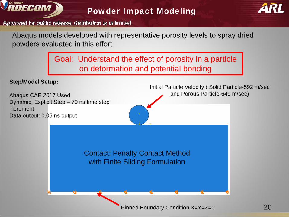
20Pinned Boundary Condition X=Y=Z=0
Initial Particle Velocity ( Solid Particle-592 m/sec and Porous Particle-649 m/sec)
Contact: Penalty Contact Method with Finite Sliding Formulation
Goal: Understand the effect of porosity in a particle on deformation and potential bonding
Step/Model Setup:
Abaqus CAE 2017 UsedDynamic, Explicit Step – 70 ns time step incrementData output: 0.05 ns output
Abaqus models developed with representative porosity levels to spray dried powders evaluated in this effort

.
Powder Impact Modeling
21
Material Properties for WC-Co based on a rule of mixtures based on the WC and Co content is typical powders (88% WC and 12% Co for instance)

.
Hardware / Nozzle Development
22
Some powders especially the highest hardness powders are sensitive to impact velocityOverworking of the deposit can lead to internal crackingModerate velocities and higher particle temperatures preferredSpecial nozzle and gun configurations can optimize deposits
Improved particle flow model to include BL and Flow separation analysis a calibrated with CFD and LDV
Provides a method for rapid nozzle design development

.
Results from Spray Dries Powder Study
23
New WC Powders with sub-micron sized carbide particles containing either Co or Ni as binder
Powder # Powder Formulation
Vendor Powder Name As received Particle Size
Achieved Hardness (HV300)
1 WC-12Co HC Stark Amperit 519.059 -30/+5 1300
2 WC-17Co HC Stark Special Order -30/+5 890
3 WC-17Ni HC Stark Special Order -30/+5 1149
4 WC-25Ni HC Stark Special Order -30/+5 798
2 3 41

.
Powder Impact Modeling
24
Increased Particle Flattening
Increased interface temperature
Von Mises Stress
Plastic Strain
Effect: More energy is dissipated in particle deformation and heating with further impacts likely on successive particles
Models show increased deformation reduced penetration increased particle flattening, and an increased interface temperature rise
.
Powder Impact Modeling
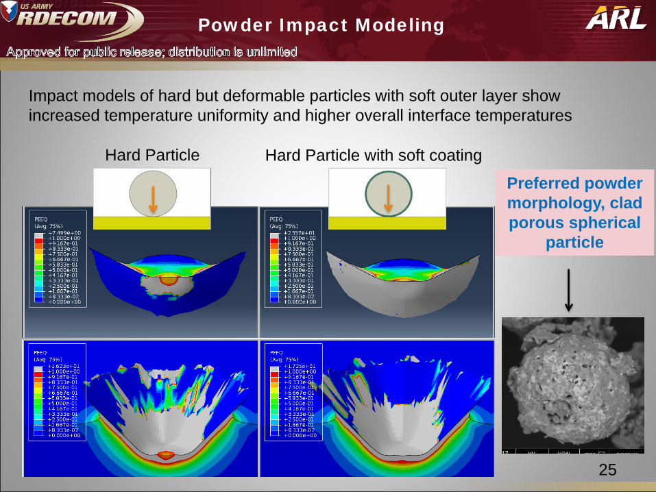
25
Preferred powder morphology, clad porous spherical
particle
Hard Particle Hard Particle with soft coating
Impact models of hard but deformable particles with soft outer layer show increased temperature uniformity and higher overall interface temperatures

.
Potential Applications
26
Many WIP coatings can be applied in bore diameters as small as 2”
Multiple short nozzle designs tuned to provide the correct balance of impact velocity and temperature