cohesity hyperconverged secondary storage with … hyperconverged secondary storage with cisco...
TRANSCRIPT
Cohesity Hyperconverged Secondary Storage with Cisco Unified Computing System: Reference Architecture

Executive Summary Hyperconvergence is becoming a norm in data centers today. Companies adopting this next generation infrastructure have realized significant savings in TCO/ROI. These savings are the result of vastly simplified architectures, lower power and cooling needs, workload consolidation, smaller hardware footprint and “pay as you grow” consumption model. What ties all these benefits together is the simplicity of managing these web scale platforms from a single UI. The design principles of distributed control and data planes that eliminate complexities in infrastructure and management make hyperconverged architectures attractive and bring overall value to end customers. Until now hyperconvergence has focused largely on primary storage workloads. However, the principles of hyperconvergence can be productively applied to secondary storage environments as well. As data continues to grow at exponential rates, companies struggle to maintain control over a sprawling landscape of secondary storage point solutions that waste resources with redundant data copies across backup, test/dev, file services and analytic workloads. A consolidated, platform-first approach to secondary storage allows for consolidation of all secondary storage use cases into a distributed, web-scale, highly-efficient, intelligent and cost-effective infrastructure. As seen below, most current enterprise data center storage landscapes resemble this architecture, with complexities built into every aspect of data management because of the point solutions and multiple redundant copies of data being stored in each of these point solutions.
©2016 Cohesity, All Rights Reserved 1.
Web Tier VM
App Tier VM
DB Tier VM
Backup
Master ServersCloud Gateway
Cloud
TapeMedia Servers
Analytics
Policy basedbackup, replication
and recovery Disaster Recovery
Archive or Tierto Cloud
Instant Restore
Cohesity Hyperconverged Secondary Storage
Data Protection Test/Dev File Shares
Analytics
Test/Dev
File Shares
vSphere + HX Series
Web Tier VM
App Tier VM
DB Tier VM
vSphere + UCS B-Series
Web Tier VM
App Tier VM
DB Tier VM
Native SQL/Oracle + UCS B-Series
Web Tier VM
App Tier VM
DB Tier VM
vSphere + HX Series
Web Tier VM
App Tier VM
DB Tier VM
vSphere + UCS B-Series
Web Tier VM
App Tier VM
DB Tier VM
Native SQL/Oracle + UCS B-Series
UCS C-240-M4 Hyper-convergedSecondary Storage powered by
UCS C-240-M4 Hyper-convergedSecondary Storage powered by
UCS C-240-M4 Hyper-convergedSecondary Storage powered by
UCS C-240-M4 Hyper-convergedSecondary Storage powered by
Figure 1: Legacy Enterprise Data Center
This not only causes the issues of sprawl, islands of fragmented storage and security concerns with the introduction of dark data. Cohesity, on the other hand has created a hyperconverged secondary storage platform that offers a radically efficient solution to fragmented data siloes by unifying all secondary use cases on a single, infinitely scalable platform. These use cases span the Tier 2 through 4 of generally acknowledged storage tiers and include Backups, DR, Test/Dev, File Shares, Archiving and Analytics.
©2016 Cohesity, All Rights Reserved 2.
Cohesity is a true Software Defined Storage System that enables policy-based provisioning and management of data storage independent of the underlying hardware. This approach aims to change physical storage hardware without disrupting application access and to give users the flexibility in terms of hardware choice to build datacenter storage services with lower costs. Cisco is the leader in enterprise-ready hyperconverged hardware. Cisco UCS is the first truly unified data center platform that combines industry standard, x86-architecture servers with networking and storage access into a single system. Together the two provide the greatest scalability, with simplest administration, at lowest cost. In this Reference Architecture document we will discuss the Cohesity Data Platform (SDS) on Cisco UCS C-Series C240-M4 platform. This brings forth to the industry a new hyperconverged secondary storage solution based on top of line Cisco C-series server platform running Cohesity intelligent, distributed DataPlatform software. This integrated solution is specifically designed to address the infrastructure challenges, operational complexities, data management challenges and fragmentation that persist across secondary storage silos within enterprise data centers today.
Intended Audience This document describes the reference solution architecture for Cohesity Data Platform with Cisco UCS C240-M4 Rack Server. It focuses on technical and business benefits of the combined solution. This document is intended for Sales Engineers, Partners, IT professional and customers who are interested in learning about and deploying Cohesity with UCS C240-M4 Rack Servers. Solution Overview Cohesity enables enterprises to take control of their increasingly complex storage environments through a hyperconverged secondary storage infrastructure. The Cohesity Data Platform can consolidate multiple use cases such as data protection, test/dev, file services and analytics onto a single web-scale platform. Today, 80% of enterprise data resides in siloed secondary storage systems. These islands of storage create inefficiency, waste and overhead expense. Cohesity consolidates silos into a highly resilient and fully redundant, web scale storage fabric, dramatically improving IT productivity and reducing long-term storage operating costs. Cohesity DataPlatform, integrated with Cisco Unified Computing System (Cisco UCS) maintains all the value that comes from secondary storage hyper-convergence while providing enterprise-class hardware for added protection and performance. Cisco UCS unifies computing, networking, management, and storage access into a single integrated physical architecture that can enable end-to-end server visibility, management and control in both bare-metal and virtualized environments. Cohesity and Cisco created this joint solution by integrating the Cohesity software onto the Cisco UCS C240-M4 rack server. The UCS C240-M4 is an enterprise-class server designed to deliver exceptional performance, expandability and efficiency for storage and I/O-intensive infrastructure workloads. Cisco UCS nodes provide a robust physical layer that has compute,memory, NVMe flash, HDDs and networking built into them. This makes this platform best suited for big data analytics, virtualization graphics-rich and bare-metal applications. The C240-M4 server can be deployed standalone or as part of the Cisco Unified Computing System (UCS). Cohesity complements Cisco hardware with a distributed file system software architecture that is designed for high availability. The nodes have share-nothing topology and there is no single point of failure or inherent bottlenecks. Consequently both performance and capacity can scale linearly as more physical nodes are added to the cluster. The distributed file system spans across all nodes in the cluster and natively provides global deduplication, compression and encryption. In addition, the Copy Data Management is built into Cohesity’s Data Platform. It allows for creation of zero-space instant writeable clones from the backups and can provision and orchestrate test & development environments. The entire platform is exposed through a single pane of glass that manages all secondary storage workflows spanning multiple clusters, geographical sites and even the cloud. By consolidating all the Tier 2-4 storage workflows into a single unified scale-out web scale platform, Cohesity and Cisco together significantly reduce TCO and improve business agility for enterprise customers. The solution eliminates fragmentation, significantly improves storage efficiency and with its inbuilt MapReduce based analytics, shines light into data which otherwise would have remained dark.

3.
Business Case The combined solution aims to provide not incremental but an order-of-magnitude additional value over existing fragmented secondary storage solutions. The solution significantly extends the value of secondary storage by ‘operationalizing’ stored data. Cohesity’s offers several key benefits including: • Introduces an extremely performant enterprise-class hardware supporting a Software Defined Storage platform
that can scale limitlessly
• Reduces data center footprint by consolidating islands of secondary storage
• Simplifies administration by managing all secondary storage workloads through a single pane of glass
• Minimizes upfront investment as customers can deploy storage in a pay-as-you-grow model
• Achieves comprehensive data protection and recovery, onsite, offsite and in the cloud
• Brings compute to data - instant access to all stored data for Test/Dev and search and analytics
• Provides full visibility to stored data with native storage analytics
The Cisco UCS C240-M4 hardware offers its key operational benefits from hardware including: • Provides UCS visibility and control to management ecosystem partners using a comprehensive XML API
• When combined with other Cisco UCS blade and rack servers, the entire solution can be managed as a single entity with Cisco UCS Manager, improving operational efficiency and flexibility
• Service profiles and templates implement role- and policy-based management, enabling more effective use of skilled server, network, and storage administrators
• Automated provisioning and increased business agility, allowing data center managers to provision applications in minutes rather than days by associating a service profile with a new or repurposed Cisco UCS C240 M4 server
• Capability to move service profiles from rack server to another rack server, blade to rack server, or rack to blade server in minutes instead of hours or days
Web Tier VM
App Tier VM
DB Tier VM
Backup
Master ServersCloud Gateway
Cloud
TapeMedia Servers
Analytics
Policy basedbackup, replication
and recovery Disaster Recovery
Archive or Tierto Cloud
Instant Restore
Cohesity Hyperconverged Secondary Storage
Data Protection Test/Dev File Shares
Analytics
Test/Dev
File Shares
vSphere + HX Series
Web Tier VM
App Tier VM
DB Tier VM
vSphere + UCS B-Series
Web Tier VM
App Tier VM
DB Tier VM
Native SQL/Oracle + UCS B-Series
Web Tier VM
App Tier VM
DB Tier VM
vSphere + HX Series
Web Tier VM
App Tier VM
DB Tier VM
vSphere + UCS B-Series
Web Tier VM
App Tier VM
DB Tier VM
Native SQL/Oracle + UCS B-Series
UCS C-240-M4 Hyper-convergedSecondary Storage powered by
UCS C-240-M4 Hyper-convergedSecondary Storage powered by
UCS C-240-M4 Hyper-convergedSecondary Storage powered by
UCS C-240-M4 Hyper-convergedSecondary Storage powered by
Figure 2: Cohesity Hyperconverged Secondary Storage

4.
• Centralized Firmware and BIOS automation via policies for all infrastructure components
Cohesity with Cisco Unified Computing Platform C240-M4 offers the following key business values Simplicity Plug and Play Installation: Cohesity Data Platform integrated with Cisco UCS C240-M4 is designed to be up and running in under an hour, eliminating the need for expensive professional services.
Effortless Configuration: Once the C240-M4 cluster has been provisioned either as standalone or UCS managed servers, storage policies can be set up in minutes on the Cohesity software platform to enable backup, replication and archival. Both solutions leverage intuitive, HTML 5 web-based management consoles and offer non-disruptive upgrades.
Pay-as-You-Grow Scaling: Both Cisco and Cohesity solutions enable the pay-as-you-grow model — customers need to buy only what they need when they need it. Adding performance and capacity is as simple as adding another C240-M4 node. The Cohesity Data Platform then incorporates all the storage resources from the new node and expands the storage footprint for backup while also growing the compute resources for test/dev and analytics.
High Availability and Non-Disruptive Upgrades: As a combined solution, Cisco and Cohesity deliver comprehensive hardware and software resiliency with hot-swappable components to handle node, network, disk and CPU/memory failures. Additionally, non-disruptive upgrades at both the software and hardware level further enable zero downtime.
Performance Enterprise-Class Hardware: C240-M4 comes with Dual Intel® Xeon® E5-2600 v3 processors for improved performance suitable for nearly all two-socket applications. The C240-M4 platform is particularly helpful for next generation scale-out storage software as it is purpose-built for storage and I/O-intensive infrastructure workloads. Cohesity’s core vision is to bring compute to data. This vision requires ample compute and NVMe flash-optimized storage. C240-M4 specifications completely meet Cohesity’s need for compute, storage and networking for an infinitely scalable secondary storage platform. App-Specific QoS: Cohesity Data Platform follows up with application-specific QoS policies for secondary storage workflows such as backup, test/dev and file services. Flash-optimization provided by C240-M4 combined with app-specific QoS, ensures that customers are getting the appropriate utilization of the storage assets across the entire datacenter. Consolidation: The C240-M4 platform as part of UCS Fabric for HW consolidation is easily managed with state of the art Service Profiles and Policies. This combined with Cohesity’s storage architecture eliminates storage sprawl and consolidates data onto the most efficient hyper-converged secondary storage platform where data is seamlessly tiered across flash, spinning disks and cloud.
Use Case - 1 Data Protection Scale-out data protection is fully backed into Cohesity’s Data Platform. Backup, recovery and DR are provided through a single unified platform eliminating complexity. Some key features of the integrated Data Protection solution are: • Fast, application-consistent backups: The scale-out nature allows parallelization of jobs thus minimizing backup
windows. Moreover application-level integration allows for application-consistent backups.
• Remote replication and DR orchestration: Built-in remote replication protect data off-site and enables disaster recovery / migrations to remote sites.
• Policy-based management: Allows policies that specify application SLA requirements including RPO, retention policies, off-site replication and cloud archival.
• De-minimis recovery points and near-instantaneous recovery times: The zero-cost snapshots support fast 15-minute RPOs and SnapTree™ technology allows for near-instantaneous RTOs.
• Indexing engine for rapid search and recovery: Cohesity DataPlatform also includes an indexing engine that lets user quickly find and restore files stored within higher-level data objects such as VMs.

5.
• Cloud integration: The unified platform fully leverages public or private clouds. It can can tier data to the cloud to extend storage capacity of the cluster for colder data. It can also use the cloud as a replication destination for disaster recovery. And finally the unified platform can archive data in the cloud for long-term retention. To know more about the Data Protection solution, please read Cohesity Data Protection White Paper Use Case - 2 Test and Development Cohesity enables copy data management by allowing enterprises to leverage the backups and accelerate time-to-market with the rapid deployment and management of test and development environments.
• Instant, zero-space clones enable businesses to quickly spin up test/dev environments from a backup or existing file share, enabling rapid test and development from actual data without any capacity overhead.
• Workflow automation provides end-to-end orchestration for test/dev environments, automating everything from creating a clone to mounting the test/dev environment in a virtual host, all with a single click.
• Instant access to data enables fast provisioning of test and development environments, drastically reducing time and complexity associated with development environment staging times.
Use Case - 3 File Services Cohesity’s scale-out system presents itself through industry standard protocols such as SMB and NFS to become an infinitely scalable, globally deduplicated and fully searchable file services platform. It delivers storage incrementally, forever eliminating expensive forklift upgrades.
• Integrated support for NFS and SMB protocols and pay-as you-grow scalability enables simple growth of your NAS storage with built-in integration for Microsoft applications and file services.
• Inline and post process data reduction technologies that are configurable on a per workload basis combined with copy data management capabilities ensures efficient storage and usage of data.
• Automated global indexing powers Google-like search, enabling instant wildcard searches for any VM, file, or object ingested into the system. This index is fully distributed across the entire cluster and is served from the cluster’s flash memory, ensuring extremely fast access to the data in the index collections.
• Authentication using Active Directory integration.
Use Case - 4 Built-in Analytics The Analytics capabilities built into the Cohesity Data Platform, powered by the highly capable C240 M4 hardware unlock the vast potential of the backed up data sets. These capabilities ensure that the data doesn’t have to be moved out of the cluster but can be analyzed in-place. Leveraging Cohesity’s powerful indexing capabilities, Cohesity Analytics provides organizations with intelligent analytics capabilities to derive business intelligence from their data. Native reporting capabilities include storage utilization trends, user metrics capacity forecasting and providing businesses with the information they need to anticipate future growth. Reports and real-time graphs of ingest rates, data reduction rates, IOPS, and latencies provide a holistic view of the performance and storage efficiency of a particular Cohesity Cluster. In addition to the native reporting and analytics, Cohesity Analytics also includes Analytics Workbench, which allows users to inject custom code to run against a particular data set in the Cluster. This code leverages all the available compute and memory resources available, as well as the abstracted MapReduce functions, to quickly answer any query. Cohesity Data Platform Cohesity Data Platform couples Cisco UCS C240-M4 hardware with intelligent, extensible software, enabling organizations to spend less time worrying about how to retrofit their legacy solutions with future needs, and more time focusing on the

6.
core functions of the enterprise. The Cohesity Data Platform is built on the file system that combines infinite scalability with an open architecture flexibility that can consolidate multiple business workloads on a single platform. With built-in, native applications to support data protection, copy data management, test and development, and in-place analytics, customers experience the benefits of consolidation right out of the box. This filesystem was built from the ground up to be the most robust and fully distributed system in the market. Unlike traditional distributed file systems that are ‘Eventually Consistent,’ Cohesity distributed filesystem leverages a purpose-built noSQL store, combined with Paxos protocols, that delivers strong consistency with the ability to make decisions rapidly, at massive scale, and without performance penalties.
The file system is comprised of several services, each one handling a key function to provide an infinitely scalable architecture while optimizing performance enabling the consolidation of multiple workloads. Cluster Manager: The Cluster Manager controls all the core services that run on a Cohesity Cluster. This layer is responsible for maintaining all configuration information, networking information, and the general state of all other components in the system. I/O Engine: The I/O Engine is responsible for all read and write operations that take place on the cluster. It is comprised of the write cache, which lives in SSD, and the tiered storage layers that span across both SSD and spinning disk. For write operations, as data is streamed into the system, it is broken down into smaller chunks, which are optimally placed onto the tier that best suits the profile of that particular chunk. The I/O Engine also ensures that all data is written to two nodes concurrently, providing write fault tolerance. This enables completely non-disruptive operations, even if a node were to become unavailable during a given operation. For read operations, the I/O Engine receives the location information of the data from the Distributed Metadata Store and fetches the associated chunk(s). If a particular chunk of data is frequently requested in a short period of time, that chunk is kept in SSD to ensure quick access and optimized performance on subsequent requests. Metadata Store: The Metadata Store is a consistent key value store that serves as the file system metadata storage repository. Optimized for quick retrieval of file system metadata, the Metadata Store is continually balanced across all nodes within the cluster (accounting for nodes that are added or removed from the cluster). The Metadata Store ensures that three copies are maintained at any point in time, so that data is always protected, even in the event of a failure.
Cohesity DataPlatform
Ingest Engine
Application Management
Storage Services
Dedupe EncryptionIndexing ReplicationSnap Tree Orchestration
UCS C-240-M4 Hyper-convergedSecondary Storage powered by
UCS C-240-M4 Hyper-convergedSecondary Storage powered by
UCS C-240-M4 Hyper-convergedSecondary Storage powered by
CohesityProtection
CohesityTest/Dev
CohesityAnalytics
FileServices
Figure 3: Cohesity Software Defined Storage Platform
7.
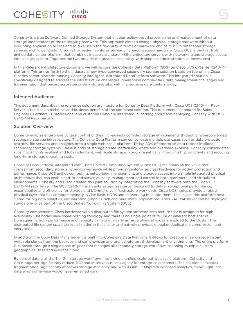
Cohesity Storage Services The next layer in the Cohesity Data Platform architecture consists of the Cohesity Storage Services, which provide the storage efficiency capabilities that customers depend on at a scale that no other solution can achieve. Snapshots Cohesity SnapTree TM for managing data copies: In legacy storage solutions, snapshots (of a file system at a particular given point in time) form a chain, tracking the changes made to a set of data and form the basis for organizing and storing copies of data. Every time a change is captured, a new link is added to the chain. As these chains grow with each and every snapshot, the time it takes to retrieve data on a given request grows because the system must re-link the chain to access that data. Cohesity’s patented SnapTree™ technology creates a tree of pointers that limits the number of hops it takes to retrieve blocks of data, regardless of the number of snapshots that have been taken. SnapTree uses a B+ tree data structure such that access to any point in the tree takes a fixed number of hops no matter how many snapshots there are, without having to rebuild any chain linkage. Because SnapTree is implemented on a distributed file system, every node sees the same nested structure of the chain with a fixed depth independent of where the actual data is stored in the cluster. This is what allows the platform to keep snapshots fully hydrated. Keeping the snapshots fully hydrated improves the recovery times of any snapshot from t0 to tn because it does not incur the time penalty of traversing the entire chain of changes (Figure 6). This capability is available with the Integrated Cohesity DataProtect solution.
The figure below shows how data is accessed using SnapTree.
Datafile reconstruction using Conventional Snapshot images
Datafile reconstruction using Cohesity SnapTree images
Unbounded accumulatedtraverses (n) to reconstructA, B, Cn
Always fixed traverses(2 in this example) to reconstructA, B, Cn
Time
A
A
C0B
B C0 C1 C2 C3 Cn
S0
C1
S1
C2
S2
C3
S3
Cn
Sn
S0 S1 S2 S3 Sn
Figure 4: Cohesity’s SnapTree™ powered snapshots vs. traditional snapshots
8.
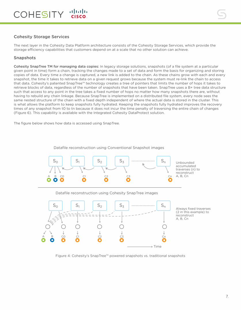
Global deduplication and compressionCohesity leverages a unique, variable-length data deduplication technology that spans an entire cluster, resulting in significant savings across a customer’s entire storage footprint. With variable-length deduplication, the size is not fixed. Instead, the algorithm divides the data into chunks of varying sizes based on the data characteristics. The chunk size is varied in real time in response to the incoming data which results in greater data reduction than fixed-size deduplication. The efficiency benefit of variable-length deduplication compounds over time as additional backups are retained. Cohesity also allows customers to decide if their data should be deduplicated in-line (when the data is written to the system) or post-process (after the data is written to the system) to optimize the backup protection jobs against backup time windows. Cohesity also provides compression of the deduped blocks to further maximize space efficiency. See figure below for further clarification.
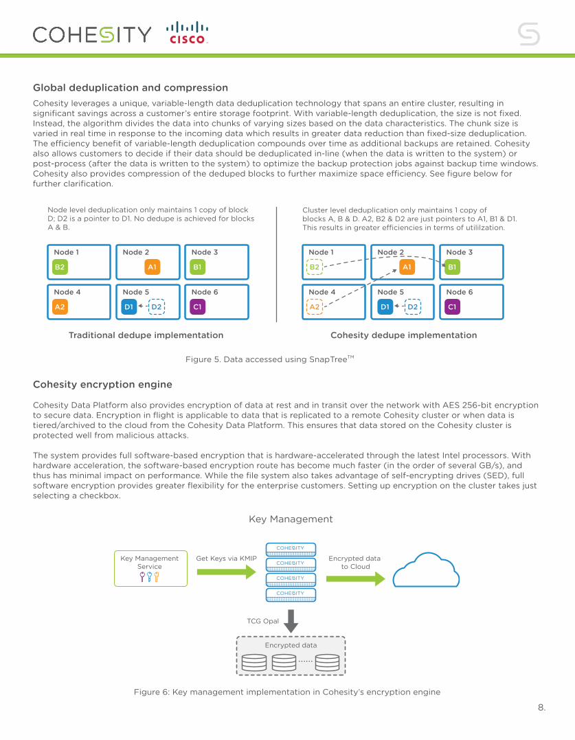
Cohesity encryption engine Cohesity Data Platform also provides encryption of data at rest and in transit over the network with AES 256-bit encryption to secure data. Encryption in flight is applicable to data that is replicated to a remote Cohesity cluster or when data is tiered/archived to the cloud from the Cohesity Data Platform. This ensures that data stored on the Cohesity cluster is protected well from malicious attacks. The system provides full software-based encryption that is hardware-accelerated through the latest Intel processors. With hardware acceleration, the software-based encryption route has become much faster (in the order of several GB/s), and thus has minimal impact on performance. While the file system also takes advantage of self-encrypting drives (SED), full software encryption provides greater flexibility for the enterprise customers. Setting up encryption on the cluster takes just selecting a checkbox.
Node level deduplication only maintains 1 copy of block D; D2 is a pointer to D1. No dedupe is achieved for blocks A & B.
Traditional dedupe implementation Cohesity dedupe implementation
Cluster level deduplication only maintains 1 copy of blocks A, B & D. A2, B2 & D2 are just pointers to A1, B1 & D1. This results in greater e�ciencies in terms of utililzation.
B2
Node 1
A1
Node 2
B1
Node 3
A2
Node 4 Node 5
C1
Node 6
B2
Node 1
A1
Node 2
B1
Node 3
A2
Node 4
D1 D2
Node 5
C1
Node 6
D1 D2
Physical and Logical separation of encryption keys
Key Management
Partition 0 hosts data for IT & Sales Departments
Key ManagementService
Get Keys via KMIP
TCG Opal
......Encrypted data
HR View Box uses
for encryption
Partition 1 hosts HR
Cluster
IT View Box uses for encryption
Sales View Box uses for encryption
Encrypted data to Cloud
Figure 6: Key management implementation in Cohesity’s encryption engine
Figure 5. Data accessed using SnapTreeTM

9.
Intelligent Data Placement Intelligent data placement ensures that data is always available, even in the event of a node failure. When data is written to a Cohesity Cluster, a second copy of that data is instantly replicated to another node within the cluster. For customers who have multiple solution Blocks (a chassis with one or more UCS Nodes) or racks, Cohesity will always optimize the placement of the data by placing the second copy on a different block or in a different rack, providing an even higher level of fault tolerance. For customers with stricter fault tolerance requirements, the Replication Factor (RF), or number of copies of data that are replicated within a Cluster, can be adjusted to fit their needs. This intelligent placement, or sharding, of data also enhances the performance characteristics of the data placed on the cluster. As the data hits the cluster, it is broken down into smaller bite-sized chunks (typically 8K to 24K). By spreading data across all nodes of a cluster the I/O load is shared across all available resources and eliminates the notion of a ‘Hot Node’ or ‘Hot Disk’ which would get accessed more frequently and would create an I/O bottleneck.
Indexing Engine The Indexing Engine is responsible for inspecting the data that is stored in a cluster. On its first pass, the Indexing Engine grabs high-level indices for quick data retrieval around top-level objects, such as Virtual Machine (VM) names and metadata. On its second pass, the Indexing Engine cracks open individual data objects, such as Virtual Machine Disks (VMDKs), and scans individual files within those data objects. This native indexing enables rapid search-and-recover capabilities to quickly find and restore files stored within higher-level data objects such as VMs. Cisco Unified Computing System Cisco UCS is an integrated computing infrastructure with embedded management that automates and accelerates deployment of applications, including virtualization and cloud computing. It can handle scale-out and bare-metal workloads as well as in memory analytics. It allows edge computing that supports remote and branch locations and massive amounts of data from the Internet of Things (IoT). The Cisco UCS is designed as a purpose-built system for the post-virtualization age. It doesn’t have the burden of supporting an existing traditional server product line, which gives it an immense amount of design freedom. Innovations in silicon are employed at every level of system’s architecture to achieve the best performance. The design goes beyond manual integration of components and employs a model in which policies guide configuration: a model that scales and allows routine tasks to be completely automated regardless of server type or application architecture. This philosophy allows Cisco UCS to deliver rapid scalability and deployment thereby increasing IT productivity and business agility. Initially focused on providing a platform for server virtualization, Cisco UCS is designed fundamentally to evolve to support a wide range of application and server architectures. Today, Cisco UCS can support all the applications in the data centers around the world both in smaller branch offices and remote offices. It supports a heterogeneous collection of servers—including blade and rack servers. It supports applications that scale up and
NODE 1 NODE 2 NODE 3 NODE 4
VMDK VMDK
Figure 7: Intelligent data placement across nodes for fast access and availability through node failures

10.
servers that scale out—all with a single policy-based management and connectivity model. Because it can support all the applications under the same management model, it can help overcome the challenges of workload diversity and support a rapid operational tempo. Cisco UCS helps to standardize IT processes, allowing IT departments to work at a higher level, defining policies and allowing automation to handle routine administrative tasks. It is the first self-aware, self-integrating, unified system that automates system configuration in a reproducible, scalable manner. As it recognizes new components added to the system, it places new server resources in pools that simplify the allocation and sharing of resources, allowing IT to more rapidly move new servers into production and increase overall resource utilization. It incorporates a simplified architecture that eliminates the need to have different network architecture for each application allowing scaling without having to reevaluate whether network resources are sufficient. It makes physical servers and virtual machines equivalent so that both can be managed with same levels of visibility and control. The system is intelligent infrastructure that is configured through integrated, model based management. Server identity, personality, and I/O connectivity is abstracted so that the system accomplishes for physical environments what hypervisors accomplish for virtualized ones. • Cisco UCS enables running of any workload on any resource with dynamic provisioning, making it the ultimate
platform for unifying the data center. A hierarchy of Cisco management tools extends this concept across all the data centers and remote locations.
• Cisco UCS Central Software uses the same model based management to support up to 6000 servers regardless of location as if they were in a single Cisco UCS domain.
• Cisco UCS Director provides comprehensive infrastructure automation and orchestration, managing all the resources in Cisco Integrated Infrastructure solutions, including Cisco UCS, storage, and higher level switching infrastructure.
• Cisco UCS Director automates the workflows, and it enables IT-as-a-service (ITaaS) offerings by providing a self-service portal through which administrators and clients can order infrastructure instances that are configured on demand.
The fundamental, standards-based XML API that the platform exposes to the outside world has been accepted and incorporated into third-party management tools from a large ecosystem of third-party vendors. As the pressures to support increasing architectural diversity with an ever-increasing operational tempo continue unabated, Cisco UCS is the single platform that can adapt to support the customers at every step. Cisco Unified Computing System Concepts Cisco UCS is the first truly unified data center platform that combines industry standard, x86-architecture servers with networking and storage access into a single system. The system is intelligent infrastructure that is automatically configured through integrated, model-based management to simplify and accelerate deployment of all the applications in a data center.
Powering Servers with Cisco Innovations The system’s x86-architecture rack and blade servers are powered exclusively by Intel® Xeon® processors and enhanced with Cisco innovations. These innovations include the capability to abstract and automatically configure the server state, built in virtual interface cards (VICs), and industry-leading memory capacity. Cisco’s enterprise class servers deliver world-record performance to power mission-critical workloads. Cisco’s cloud-scale servers support a lower-performance, bare-metal deployment model in which massive numbers of servers support many instances of a single application. These servers, in combination with simplified, unified architecture, increase IT productivity and provide superior price-to-performance ratios for lower total cost of ownership (TCO). Simplifying Three Networks into One Building on Cisco’s strength in enterprise networking, Cisco UCS is integrated with a standards-based, high-bandwidth, low-latency, virtualization-aware 10-Gbps unified fabric, with a new generation of Cisco UCS fabric enabling an update to 40 Gbps. Cisco Single Connect technology is implemented with an end-to-end system I/O architecture that uses Cisco Unified Fabric and Cisco Fabric Extender Technology (FEX Technology) to connect every Cisco UCS server within a single network and a single network layer. The system is wired once to support the desired bandwidth, and it carries all Internet protocol, storage, management, and virtual machine traffic with security isolation, visibility, and control equivalent to that of physical networks. The network fabric exceeds the bandwidth demands of today’s multi core processors and eliminates the cost of separate networks for each type of traffic while increasing workload agility, reliability, and performance. The Cisco UCS I/O architecture is based on open standards and is reliable, available, and secure.

11.
Bringing Automation to Information Technology Cisco UCS is intelligent infrastructure that is self-aware and self-integrating.
The system is built from the beginning so that every aspect of server identity, personality, and connectivity is abstracted and can be applied through software.
• With Cisco UCS, servers are configured automatically, eliminating the manual, time consuming, error-prone assembly of components into systems.
• With Cisco VICs, even the number and type of I/O interfaces are programmed dynamically, making every server ready to power any workload at any time.
• With Cisco composable infrastructure, even storage devices are abstracted and included as part of dynamic server definition.
This abstraction allows Cisco UCS to do what no hypervisor can do: adapt every aspect of the hardware configuration to propel applications with the exact balance of resources that make them perform best.
Using Policies to Align Configurations with Workloads With integrated, model-based management, administrators manipulate a model of a desired system configuration and associate a model’s service profile with hardware resources, and the system configures itself to match the model. This automation accelerates provisioning and workload migration with accurate and rapid scalability. The process of establishing and maintaining configuration management databases (CMDBs) can be automated through the system’s XML API, facilitating approaches based on Information Technology Infrastructure Library (ITIL) concepts. The result is increased IT staff productivity, improved compliance, and reduced risk of failures due to inconsistent configurations. Directly Connecting Servers and Virtual Machines to the Network With Single Connect technology, the unified fabric requires fewer components and networks, and Cisco fabric extenders reduce the number of network layers by directly connecting physical and virtual servers to the system’s fabric interconnects. This combination eliminates blade server, top-of-rack and hypervisor-based switches by logically connecting fabric interconnect ports directly to individual servers and virtual machines. Virtual networks are now managed exactly the same way as physical networks, but have massive scalability. This capability represents a radical simplification compared to traditional systems, reducing capital and operating costs while increasing business agility, simplifying and accelerating deployment, and improving performance.
Scaling Without Complexity The combination of unified fabric and Cisco fabric extenders in Single Connect technology creates a system with one network layer and one point of management and connectivity for the entire system. As a result, Cisco UCS scales more gracefully, in smaller increments, and at lower cost than other systems. With low cost and low-power-consuming fabric extenders supporting the system’s growth, the infrastructure cost per server is dramatically lower than for traditional systems. Because Cisco fabric extenders act as distributed line cards and are implicitly managed by the system’s fabric interconnects, the system can grow without the need to add a single management point. Fewer components and management points contribute to easier and more rapid scaling with lower capital and operating costs.
Increasing Energy Efficiency Every aspect of Cisco UCS is designed for energy efficiency. • The rack servers are designed for minimal airflow obstruction, reducing the number of watts (W) used by cooling
fans.
• Power supplies are sourced to maintain high efficiency even at moderate power utilization levels.
• The elimination of blade chassis switching, top-of-rack switching, and bladechassis management modules reduces the number of devices that need to be powered, reducing overall power consumption.

12.
• The elimination of multiple parallel networks for IP, storage, and management traffic reduces the number of network interface cards (NICs) and host bus adapters (HBAs) and corresponding upstream ports that need to be powered and cooled.
• Large memory capacities help support large virtual machine footprints in 2-socket servers, eliminating the need to use 4-socket servers just to have a larger memory capacity and thereby also eliminating the energy cost. Cisco originally led the industry with Cisco Extended Memory Technology, and today offers one of the largest memory capacities available in a half-width blade server.
• Intel Xeon processors used in Cisco UCS servers adjust their energy consumption to the workload by scaling down energy use in small increments as workload conditions permit, and scaling up the processor clock rate when workload conditions demand and thermal conditions permit.
Solution ValidationThis solution combines the Cohesity software stack with the Cisco Unified Computing System C240 M4 servers to create tier 2-4 storage cluster. The design illustrates the real world use case when using a hyperconverged storage solution for primary data and applications and secondary storage providing tier 2-4 storage, i.e. file share, test/dev and backup & archive in a single storage platform.
The Cohesity solution running on Cisco Unified Computing System is designed to be simple to deploy and offers simple scalability. The reference architecture specifically validates the integration performed deploying the backup solution on Cisco HyperFlex. Operational tasks are validated including performing VM-centric data migration, setting up VM and application backups and recovery, dealing with various failure scenarios, and running application workloads. The solution comprises a Cohesity cluster of four Cisco UCS C240 M4 systems connected to a 4 node Cisco HyperFlex cluster.
Topology The following diagram illustrates the solution topology.
Figure 8: Cisco UCS with Cohesity hardware topology
Cisco UCS_Cohesity Hardware specifications
Functionality TestingThe Cohesity software running on Cisco UCS C240 M4 servers offers an integrated solution for backup and tier 2 storage needs. This section outlines the testing of the solution’s following functionalities: Setup and Initial Cluster Configuration Using standard installation methods, Cohesity was installed onto 4 Cisco C240 M4 Servers to form a tier 2 storage cluster. The setup was simple and straightforward and was performed quickly with no issues or delays.

13.
Figure 9: Setting up Cohesity cluster for the first time
Figure 10: Selecting which nodes will become part of the cluster

14.
Cluster interfaceUsing the built in user interface multiple storage operations were performed including: cluster configuration, management and backup tasks. The user interface is built into the cluster software and accessed via a web browser and provides cluster setup and defining all backup jobs. Multiple operations such as creating different logical containers (View Boxes), creating data protection jobs, performing backups to Cisco HX series HCI system, creating filesystem mount points and presenting these to external ESXi hosts, and recovery tasks were all performed through the Cohesity interface.
Figure 11: Dashjboard for the Cohesity Data Management Platform

15.
Storage ProtectionMultiple ESXi hosts were selected from an existing Cisco HyperFlex HCI cluster to be the backup as a source whose VMs would be protected. Multiple types of protection jobs were configured with different schedule time frames, full and incremental backup policies and retention policies. Multiple View Boxes were configured with various storage policies for dedup, compression, and encryption. All of these tasks are performed from the Cohesity GUI and no interaction with the primary data cluster software stack was required.
Figure 12: View Boxes can be configured with different protection policies

16.
Restore VM from backup to original locationThis exercise will outline the recovery of VMs that were deleted from the Cisco HyperFlex datastore and put back into the original location. 12 different VMs were deleted from the Cisco HyperFlex datastore and removed. Using the Cohesity GUI a restore job was started and the 12 missing VMs were selected from one of the backup View Boxes. These VMs were set to restore to their original location with the original VM names. A new NFS mount was created and attached to each of the ESXi hosts in the HyperFlex cluster. All the missing VMs were orginally located here. Multiple sets of the missing VMs were storage vmotioned from the Cohesity created datastore to the original datastore. Each of the VMs were started backup with no missing data or issues.
Figure 13: Dashboard displaying all the protection jobs configured in the system

17.
Restore individual VM files from backupCohesity can restore an individual file and place it back to the original location or alternate location. A test was setup to simulate an accidental deletion of multiple files from a VM running windows on a Cisco HyperFlex cluster. The files needed to be restored to the original location on the OS. Using the Cohesity GUI the user would select the protection job and recovery task then indicate that a File or Folder will need to be recovered. There are two ways to find the files, either by file or folder name or by selecting the VM and manually searching for the missing files using the built-in suggestive search. The latter method was used to point to the VM and select the 21 missing files. The restore operation was completed and within a few seconds the files were fully recovered onto the VM in the original directory.
Figure 14: Restoring VMs to the original location

18.
Figure 15: Restoring individual files in a VM

19.
Presentation of storage for Test/Dev Using the cluster to present filesystem storage to external nodes needs to be simple and flexible. In the GUI multiple NFS and SMB shares were created and presented to ESXi Host on the HyperFlex cluster as well as a Windows virtual machine running on another ESXi host with direct mapping. Process was simple and normal filesystem mounting procedures for each OS was followed with no issues. In the following screen HX_TestDev is a Cohesity View that is created in the Cohesity UI, and it can now be exposed with both NFS and SMB 3.0 protocols to client systems.
Cohesity storage for Windows home directories The Cohesity cluster can be used to present SMB filesystem storage for windows users or VDI desktops. In the web GUI, multiple SMB shares were created and these were presented to Windows virtual machines running on another ESXi host and a bare metal windows server. This process was simple and normal filesystem mounting procedures for each OS was followed with no issues. In the following example, a Cohesity view is shown to be mapped as a remote network drive inside of a Windows server. This network drive can be integrated with AD file level permissions and can be used as a home directory repository for Active Directory users.
In the following case we are going to mount the above created NFS filesystem as an NFS Datastore to complement the HyperFlex primary storage system for Tier 2 scale out storage to run 2nd tier VMs.
Figure 16: Presenting a view to external host through NFS/SMB
Figure 17: Datastore details

20.
Figure 18: Cohesity cluster presented as a remote network drive on Windows
Figure 19: Cloning workflow on Cohesity - setting options
Clone Protected VMs for Test/Dev Clones of running production VMs can be made and presented back to the Cisco HyperFlex ESXi cluster for testing and development. This enables the use of real live production writable clone VMs for testing with complete separation of the parent VMs. An existing backup job was used to select multiple VMs from the Cohesity storage platform to instantly create zero-copy clones for test & dev use. The clones could be created instantly because Cohesity keeps all backed up data sets fully hydrated at all times. These VMs were restored to the HyperFlex cluster into a datastore that was automatically created and mounted to each of the HyperFlex nodes.

21.
Figure 20: Cloning workflow in Cohesity - selecting VM objects
Figure 21: Cloned VMs presented to HyperFlex

22.
Connecting Cohesity storage for 3rd party backup software utilization Cohesity supports using existing backup software as the source of the backup jobs, and Cohesity volumes as the target disks. A virtual backup software environment was setup using a leading 3rd party backup software and configured to use Cohesity SMB file shares. New Cohesity View Boxes were configured for multiple SMB mount points and within this external backup software a new scale-out backup repository was created. Multiple backup jobs were created within the backup software interface and groups of VMs running on the HyperFlex Cluster were selected to be backed up.
Cluster scalability and growth Validation of scaling the Cohesity cluster by adding a fourth node to an existing 3 node cluster while running a protection job was done. The performance of the cluster backup process increased linearly with the new node dynamically starts taking load from a currently running protection job. Adding the new node was a simple process utilizing the web UI.
Figure 22: Setting up Cohesity as a target for 3rd party backup software
Figure 23: Status of the three nodes in a cluster
Figure 24: Adding a fourth node to the cluster
23.
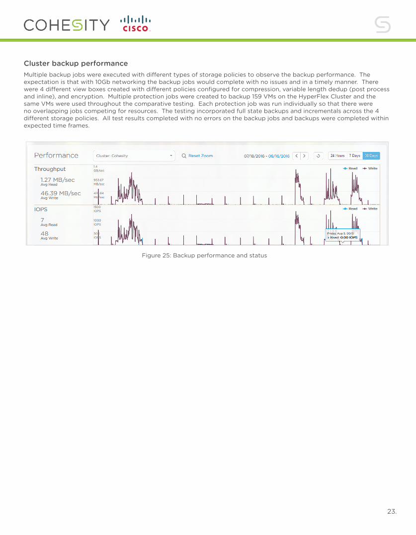
Cluster backup performanceMultiple backup jobs were executed with different types of storage policies to observe the backup performance. The expectation is that with 10Gb networking the backup jobs would complete with no issues and in a timely manner. There were 4 different view boxes created with different policies configured for compression, variable length dedup (post process and inline), and encryption. Multiple protection jobs were created to backup 159 VMs on the HyperFlex Cluster and the same VMs were used throughout the comparative testing. Each protection job was run individually so that there were no overlapping jobs competing for resources. The testing incorporated full state backups and incrementals across the 4 different storage policies. All test results completed with no errors on the backup jobs and backups were completed within expected time frames.
Figure 25: Backup performance and status

Cohesity, Inc. Address 451 El Camino Real, Santa Clara, CA 95050Email [email protected] www.cohesity.com ©2016 Cohesity. All Rights Reserved.
@cohesity 10.24.
Conclusion This reference architecture demonstrated how we have leveraged the key strengths of the Cisco UCS architecture and Cohesity data platform to consolidate secondary storage workflows. The architecture offers industry’s top compute infrastructure and Cisco UCS networking fabric running Cohesity’s scale-out secondary storage platform with its integrated backup and recovery software. All of the secondary storage workflows functionality including backup & recovery, test/dev and SMB/NFS file shares is delivered through a single pane of glass. Cohesity can backup VMs and provide a storage repository for Cisco HyperFlex converged infrastructure solutions as well as bare metal systems. By exposing itself as an NFS or SMB file share, Cohesity can store datasets being backed up by 3rd party backup software. Cohesity can also spin up the backed up VMs instantly to create test and development environments demonstrating how it significantly reduces the storage footprint while making the development environments considerably more agile. This provides enterprises the significant operational agility, the key motivation for deploying HCI infrastructures. Using Cohesity on Cisco UCS greatly simplifies the protection of VMs and applications in the datacenter and offers expanded storage for testing and development. Authors :
Chris Dunk - Technical Marketing Engineer, Cisco Systems Inc.
Damien Philip - Systems Engineer, Cohesity Inc.
Vivek Agarwal - Head of Corporate Development, Cohesity Inc.
About Cohesity Cohesity delivers the industry’s first solution for secondary storage consolidation. Cohesity enables companies of all sizes to bring order to their data chaos by converging storage workloads, including file services, data protection, Test/Dev, and in-place analytics, onto an infinitely scalable, intelligent data platform. With Cohesity, customers can manage and protect data seamlessly, use it efficiently, and learn from it instantly. Cohesity is headquartered in the heart of Silicon Valley, California with a global presence across the Americas, EMEA, and APAC.