coherent doppler lidar for wind speed measurements...
TRANSCRIPT
Coherent Doppler lidar for wind speed measurements in atmospheric boundary layer
Cyrus F Abari
DTU Wind Energy, Technical University of Denmark
Table of contents:
• Introduction (CW vs. pulsed CDLs)
• Signal modeling in pulsed CDL
• Noise in CDLs
• Practical considerations
• An all-fiber pulsed CDL
• Design example
• Challenges in all-fiber pulsed CDL design
2 9 October 2014
DTU Wind Energy, Technical University of Denmark
Continuous wave vs. pulsed coherent Doppler lidars (CDL)
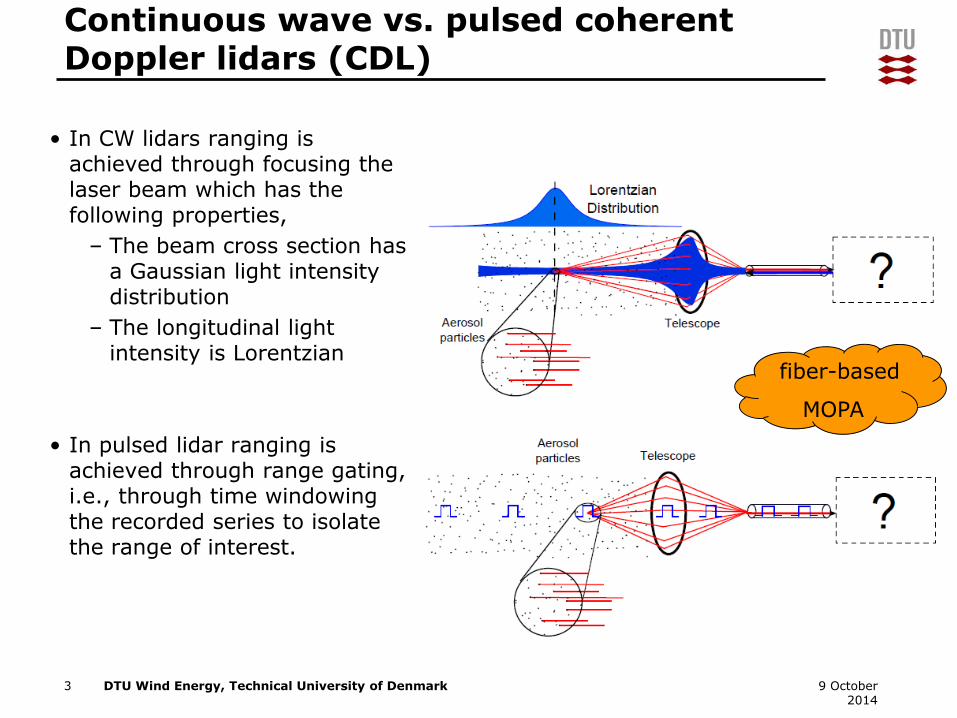
• In CW lidars ranging is achieved through focusing the laser beam which has the following properties,
– The beam cross section has a Gaussian light intensity distribution
– The longitudinal light intensity is Lorentzian
• In pulsed lidar ranging is achieved through range gating, i.e., through time windowing the recorded series to isolate the range of interest.
3 9 October 2014
fiber-based
MOPA
DTU Wind Energy, Technical University of Denmark
Pulsed CDL signal modeling
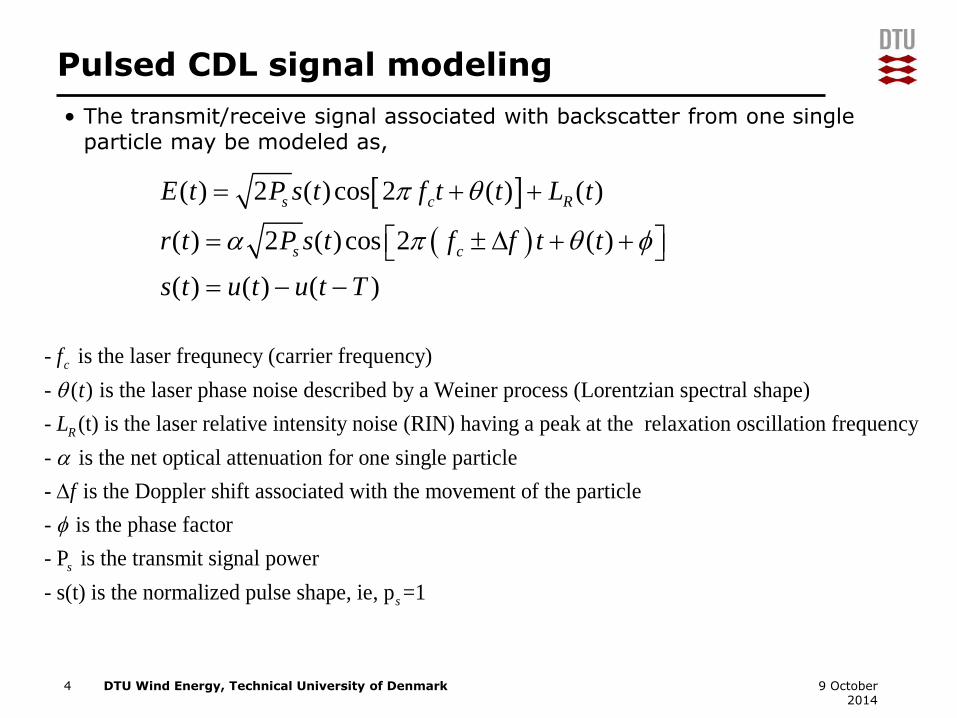
• The transmit/receive signal associated with backscatter from one single particle may be modeled as,
4 9 October 2014
( ) 2 ( )cos 2 ( ) ( )
( ) 2 ( )cos 2 ( )
( ) ( ) ( )
s c R
s c
E t P s t f t L t
r t P s t f f t t
s t u t u t T
t
- is the laser frequnecy (carrier frequency)
- ( ) is the laser phase noise described by a Weiner process (Lorentzian spectral shape)
- (t) is the laser relative intensity noise (RIN) having a pea
c
R
f
t
L
k at the relaxation oscillation frequency
- is the net optical attenuation for one single particle
- is the Doppler shift associated with the movement of the particle
- is the phase factor
- P
f
is the transmit signal power
- s(t) is the normalized pulse shape, ie, p =1
s
s

DTU Wind Energy, Technical University of Denmark
• If somehow a CTFT could be carried out on the received optical signal
5 9 October 2014
2 22 2
2
( ) ( ) ( ) ( )2 2
( ) ( ) ( )2 2
2 2s s
s s
j j
c c
c c
R F S F e F f f e F f f
R F S F f f S F
P P
Pf
Pf
Pulsed CDL signal modeling
DTU Wind Energy, Technical University of Denmark
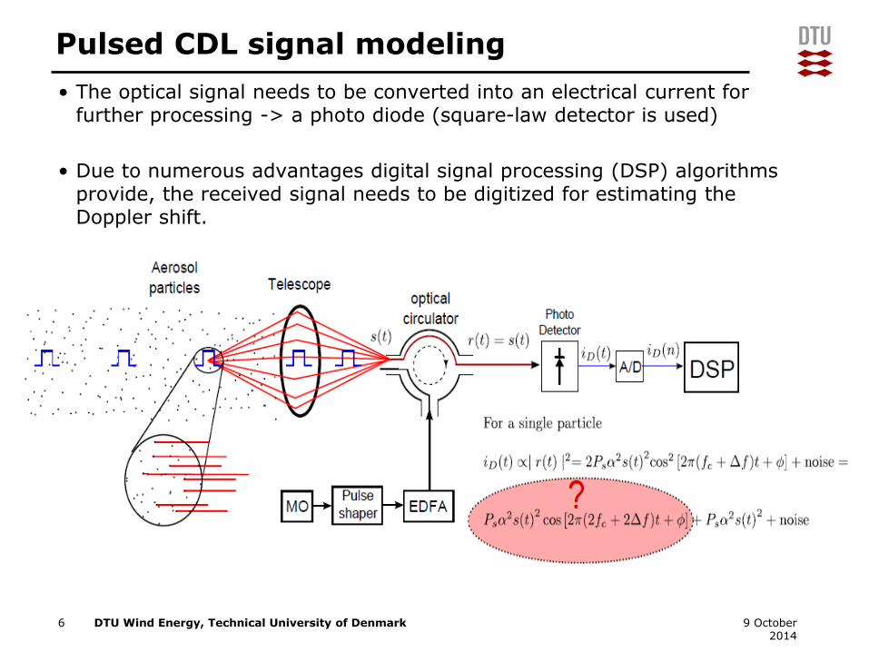
• The optical signal needs to be converted into an electrical current for further processing -> a photo diode (square-law detector is used)
• Due to numerous advantages digital signal processing (DSP) algorithms provide, the received signal needs to be digitized for estimating the Doppler shift.
6 9 October 2014
Pulsed CDL signal modeling
DTU Wind Energy, Technical University of Denmark
• Theoretically, the detector output can be directly digitized for further processing. However,
– The detector has a limited BW and can’t follow the high frequency variations
– The A/D as well as other electronic components have a limited BW
• As a result, the optical signal needs to be down-converted (translated) into a lower frequency region where digital processing of the signal is feasible.
• This is a familiar concept in Radio communications (heterodyning!)
• The down-conversion process is called beating, heterodyning, coherent detection, etc.
• Depending on the down-conversion procedure various front-end architectures in lidars may be realized. (will be discussed, next lecture)
7 9 October 2014
Pulsed CDL signal modeling

DTU Wind Energy, Technical University of Denmark
• The transmit and receive signal (for a detector responsivity of 1) may be modeled as,
8 9 October 2014
Pulsed CDL signal modeling

DTU Wind Energy, Technical University of Denmark
Noise in CDLs
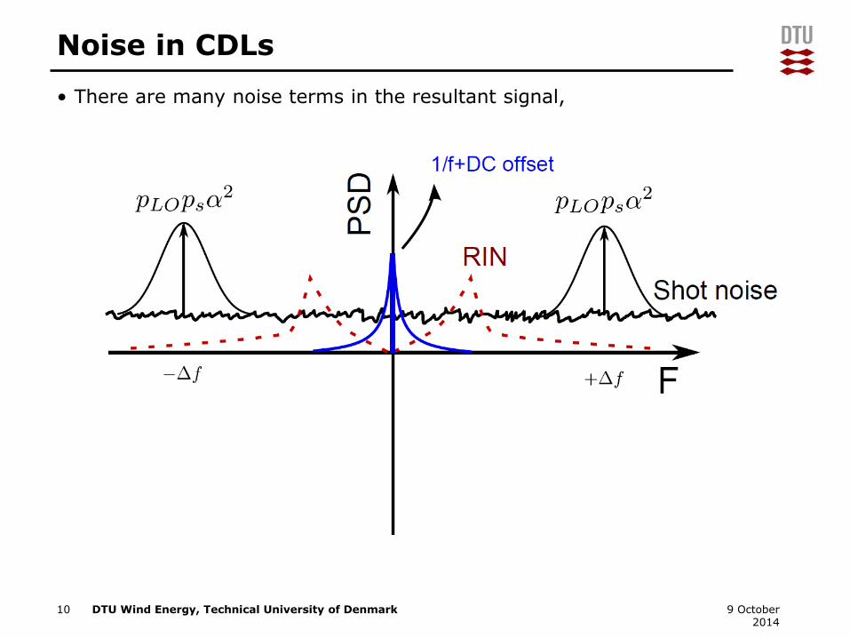
• Noise plays an important role in signal detection in lidars. There are many noise terms in the resultant signal,
– DC noise
– Detector’s shot noise
– Thermal noise
– 1/f noise
– Interferometric noise
– Dark noise
– RIN noise
– Speckle noise
• DC noise can be easily filtered out using a high-pass filter
• Shot noise power is primarily a function of the LO power. It has a Gaussian distribution, why not Poisson?
• Thermal noise and dark current noise are negligible
• Interferometric noise is due to leakage in optical components such as circulator; it is not an issue in pulsed lidars but poses a problem in CW
• RIN noise is mainly due to output power fluctuations of the laser
9 9 October 2014
Speckle noise
DTU Wind Energy, Technical University of Denmark
Noise in CDLs
• There are many noise terms in the resultant signal,
10 9 October 2014
DTU Wind Energy, Technical University of Denmark
CNR in CDLs
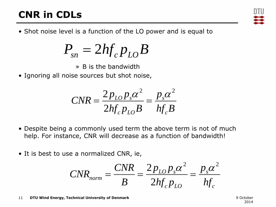
• Shot noise level is a function of the LO power and is equal to
» B is the bandwidth
• Ignoring all noise sources but shot noise,
• Despite being a commonly used term the above term is not of much help. For instance, CNR will decrease as a function of bandwidth!
• It is best to use a normalized CNR, ie,
11 9 October 2014
2sn c LOP hf p B
2 22
2
LO s s
c LO c
p p pCNR
hf p B hf B
2 22
2
LO s snorm
c LO c
CNR p p pCNR
B hf p hf
DTU Wind Energy, Technical University of Denmark
Practical considerations
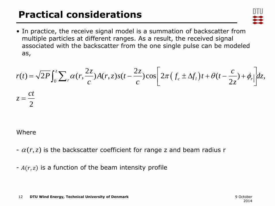
• In practice, the receive signal model is a summation of backscatter from multiple particles at different ranges. As a result, the received signal associated with the backscatter from the one single pulse can be modeled as,
Where
- is the backscatter coefficient for range z and beam radius r
- is a function of the beam intensity profile
12 9 October 2014
0
2 2( ) 2 ( , ) ( , ) ( )cos 2 ( ) ,
2
2
z
cr l r
z z cr t P r A r z s t f f t t dz
c c z
ctz
( , )r z
𝐴(𝑟, 𝑧

DTU Wind Energy, Technical University of Denmark
Practical considerations
• The signal after digitization is a time series which contains the information for all ranges. Thus, range gating needs to be performed.
• In other words, the signal associated with the desired signal is a windowed version of the original signal.
• As a result, the processed Doppler spectrum is,
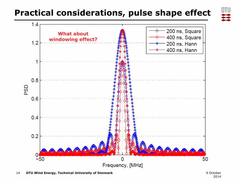
• The effect of windowing as well as pulse shape is spectral broadening and leakage.
• Pulse shape design is a trade-off between range resolution and spectral broadening.
• The longer the pulse the lower the spectral broadening but a worse range resolution.
• Most CDLs have a pulse length of 200-400 ns.
13 9 October 2014
( ) ( ) ( ) ( ) ( ) ( )w wr n w n r n R f W f R f
'
'
( ) ( ) ( ) ( ),
( ) ( ) ( )
wr DP f W f S f S f
W f w n w n
DTU Wind Energy, Technical University of Denmark
Practical considerations, pulse shape effect
14 9 October 2014
What about windowing effect?
DTU Wind Energy, Technical University of Denmark
Practical considerations
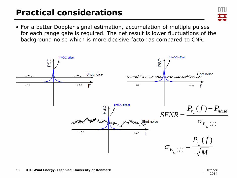
• For a better Doppler signal estimation, accumulation of multiple pulses for each range gate is required. The net result is lower fluctuations of the background noise which is more decisive factor as compared to CNR.
15 9 October 2014
( )
( )w
rw
r
P f
P f
M
( )
( )w
rw
r noise
P f
P f PSENR
DTU Wind Energy, Technical University of Denmark
• The detector should operate in shot-noise limited mode so that a maximum CNR is achieved. The detector should not operate close to saturation.
• For maximum efficiency the receive signal and LO should have the following properties,
– The signals should be coherent both temporally and spatially. Spatial incoherent signals are common due to reflections from turbulent structures in the atmosphere. The result is speckle noise.
– The polarization should be the same. The detection efficiency is the dot product between the two polarization states. A certain degree of depolarization is always present due to:
• Mirrors and optical surfaces
• Non-spherical atmospheric particles, multiple reflections
16 9 October 2014
Practical considerations
DTU Wind Energy, Technical University of Denmark17 9 October 2014
All-fiber pulsed CDLs
DTU Wind Energy, Technical University of Denmark
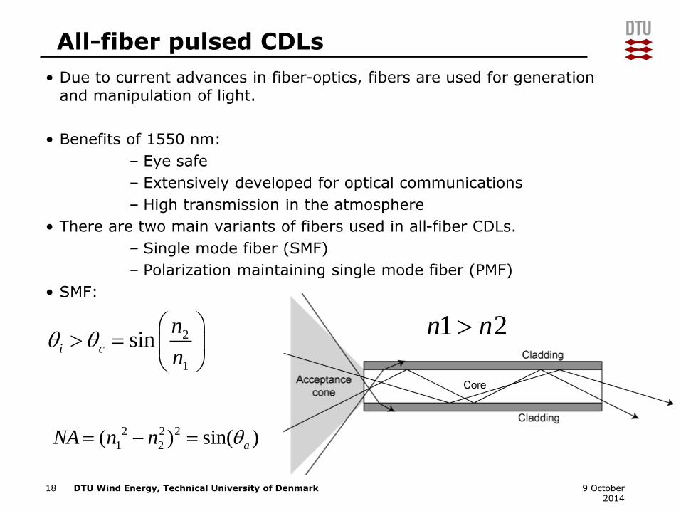
• Due to current advances in fiber-optics, fibers are used for generation and manipulation of light.
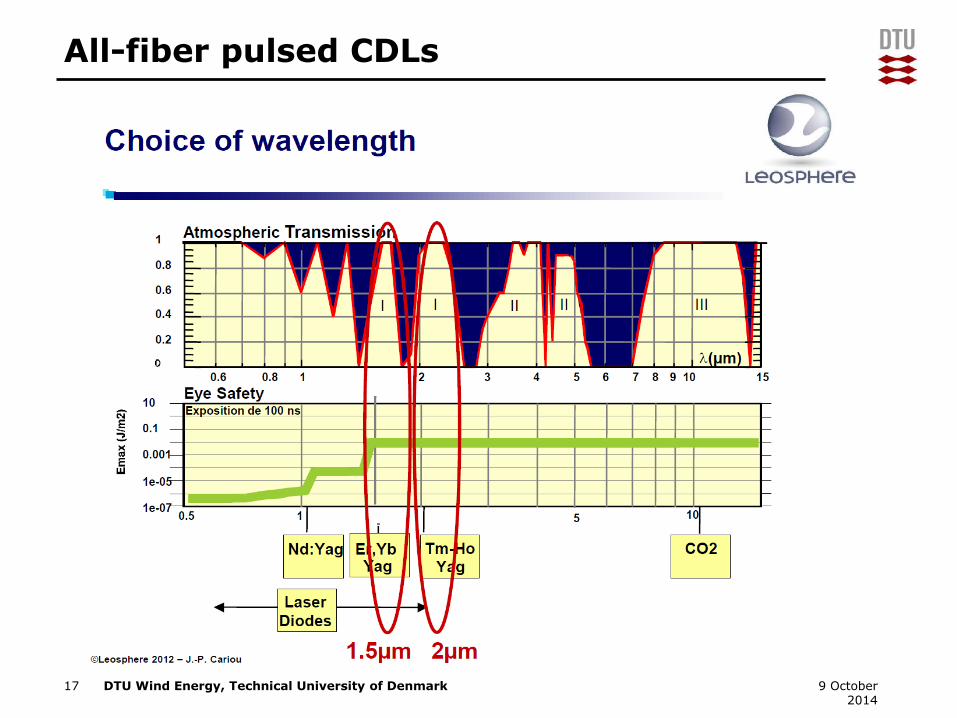
• Benefits of 1550 nm:
– Eye safe
– Extensively developed for optical communications
– High transmission in the atmosphere
• There are two main variants of fibers used in all-fiber CDLs.
– Single mode fiber (SMF)
– Polarization maintaining single mode fiber (PMF)
• SMF:
18 9 October 2014
1 2n n
2 2 2
1 2( ) sin( )aNA n n
2
1
sini c
n
n
All-fiber pulsed CDLs
DTU Wind Energy, Technical University of Denmark
All-fiber pulsed CDLs
• SMF
– Acts like a waveguide for TM00 mode of the laser.
– Due to impurities/imperfections and random fluctuations of refractive index, the polarization of light is not maintained.
– The polarization state of light is very sensitive to environmental effects such as temperature and vibrations.
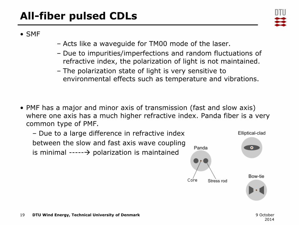
• PMF has a major and minor axis of transmission (fast and slow axis) where one axis has a much higher refractive index. Panda fiber is a very common type of PMF.
– Due to a large difference in refractive index
between the slow and fast axis wave coupling
is minimal ----- polarization is maintained
19 9 October 2014
DTU Wind Energy, Technical University of Denmark
All-fiber pulsed lidar
• Benefits of fiber lasers,
– Light is already coupled into a flexible fiber
– Due to high surface to volume ratio fiber lasers can have high powers.
– The beam quality is high
– etc.
• Generation of laser doesn’t need to be done through a fiber laser. It can be from a semiconductor laser with an acceptable linewidth and beam profile. The laser can be easily coupled into a fiber.
• For amplification, erbium dope fiber amplifiers (EDFA) provide a high output power while being compact in size. In EDFA, Erbium ions are excited with 980 nm or 1450 nm light pump. Stimulated emission at 1550 nm is responsible for amplification.
• EDFA’s can be based on SMF or PMF fibers depending on the application.
• Spontaneous Brillouin scattering is one of the most important challenges when designing EDFA’s specially in high power pulsed applications.
20 9 October 2014

DTU Wind Energy, Technical University of Denmark
Design example, pulsed CDL
21 9 October 2014

DTU Wind Energy, Technical University of Denmark
Design example, pulsed CDL
22 9 October 2014
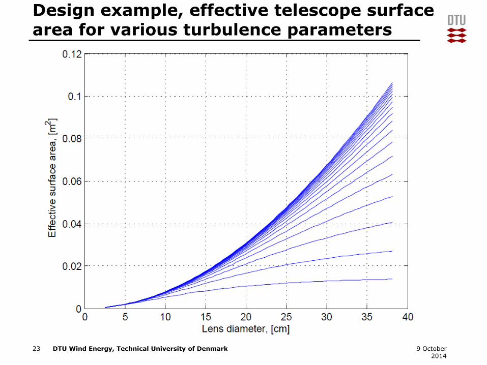
• For maximum CNR, the transmit/receive signals should have the same view of the atmosphere--- proper beam alignment needs to be done.
• Beam expansion to prevent optical damage is a very important design criteria.
What is the optimum
lens diameter?
DTU Wind Energy, Technical University of Denmark
Design example, effective telescope surfacearea for various turbulence parameters
23 9 October 2014
DTU Wind Energy, Technical University of Denmark
Challenges in pulsed lidars
24 9 October 2014
• Due strong reflections from optical surfaces, specially the telescope, the lidar (is blind) can’t detect the signal for really short ranges. For a pulse of 200 ns in length the blind region is the first 60 m.
• Pulse shaping is a critical parameter;
– as it dictates the spectral resolution
– the upper performance bounds on the estimation algorithms
– power distribution at the output of the EDFA
• Due to frequency shifting (AOM), the detection BW is limited for the exemplary receiver.
• Fiber length and beam cross-sections need to be carefully chosen at the output of the EDFA.
• Detectors should be able to recover from saturation quickly.
• Due to limited average power, lidar’s performance is a trade-off between PRR and range.

Thanks for listening!Questions?