coding schemes for the two-way relay channelsmaivu/theses/zhong_msthesis.pdfcoding schemes for the...
TRANSCRIPT

Coding Schemes for the Two-Way RelayChannels
Peng Zhong
Department of Electrical & Computer EngineeringMcGill UniversityMontreal, Canada
August 2012
A thesis submitted to McGill University in partial fulfillment of the requirements for thedegree of Master of Engineering.
c© 2012 Peng Zhong
i
Abstract
In modern transmission networks, relay plays an important role for cooperative strategies.
Several relaying strategies, such as decode-forward, compress-forward and amplify-forward,
have been proposed for relay channels and networks. However, the capacity for the general
relay channel and network is still unknown. In this thesis, we propose several relay schemes
for different relay models.
In the first part of the thesis, we propose novel partial decode-forward (PDF) schemes
for the two-way relay channel with direct link. Different from pure decode-forward, each
user divides its message into two parts and the relay decodes only one part of each. The
relay then generates its codeword as a function of the two decoded parts and forwards to
the two users. We propose PDF schemes for both the full- and half-duplex modes. Analysis
and simulation show that if for one user, the direct link is stronger than the user-to-relay
link, while for the other, the direct link is weaker, then PDF can achieve a rate region
strictly larger than the time-shared region of pure decode-forward and direct transmission
for both full- and half-duplex modes.
The second part of the thesis is based on noisy network coding, which is recently pro-
posed for the general multi-source network by Lim, Kim, El Gamal and Chung. This
scheme builds on compress-forward (CF) relaying but involves three new ideas, namely no
Wyner-Ziv binning, relaxed simultaneous decoding and message repetition. In this part,
using the one-way and two-way relay channel as the underlining example, we analyze the
impact of each of these ideas on the achievable rate region of relay networks.
In the third part of the thesis, we propose two coding schemes combining decode-forward
(DF) and noisy network coding (NNC) with different flavors. The first is a combined DF-
NNC scheme for the one-way relay channel which includes both DF and NNC as special
cases by performing rate splitting, partial block Markov encoding and NNC. The second
combines two different DF strategies and layered NNC for the two-way relay channel.
Analysis and simulation show that both proposed schemes supersede each individual scheme
and take full advantage of both DF and NNC.

ii
Abrege
Dans les reseaux de transmission modernes, les relais jouent un role important dans les
strategies cooperatives. Plusieurs strategies de relai, telles que decode-forward, compress-
forward et amplify-forward, ont ete proposees pour les canaux et reseaux a relais. Cepen-
dant, la capacite du canal a relai general et de tels reseaux reste toujours inconnue. Dans
cette these, nous proposons plusieurs strategies de relai pour differents modeles.
Dans un premier temps, nous proposons de nouvelles strategies de decode-forward par-
tiel (PDF) pour le canal a relai bidirectionnel avec lien direct. A la difference du decode-
forward classique, chaque utilisateur divise son message en deux parties, mais le relai ne
decode que l’une d’entre elles pour chacun. Le relai genere alors un mot de code en fonc-
tion de ces deux parties decodees et les transmet aux deux utilisateurs. Nous proposons
une stratgie PDF a la fois pour les liaisons half- et full-duplex. Comme le montrent les
analyses et simulations realisees, si, pour l’un des utilisateurs, le lien direct est meilleur que
le lien utilisateur-relai alors que, pour l’autre utilisateur, le lien direct est plus faible, dans
ce cas, la strategie PDF permet d’accroıtre strictement la region des debits atteignables
par rapport a la region atteinte par le partage de temps avec la strategie decode-forward
classique et la transmission directe, a la fois pour les liaisons half- et full-duplex.
La deuxieme partie de cette these s’interesse au codage de reseau avec bruit, qui a ete
aborde recemment pour les reseaux multi-sources generiques par Lim, Kim, El Gamal et
Chung. Cette strategie se base sur le relayage par compress-forward (CF), mais utilise trois
nouvelles idees, a savoir le binning de Wyner-Ziv, le decodage simultane moins contraignant
et la repetition de message. Dans cette partie, nous prenons pour exemple les canaux a
relai mono- et bidirectionnels, et nous analysons l’impact de chacune de ces idees sur la
region des debits atteignables pour les reseaux a relais.
Dans la troisieme partie de cette these, nous proposons deux strategies de codage qui
combinent le decode-forward (DF) et le codage de reseau avec bruit (NNC), avec differentes
nuances. La premiere est une strategie combinee DF-NNC pour le canal a relai monodirec-
tionnel, pour laquelle DF et NNC representent des cas particuliers par partage de debit,
de meme que lencodage partiel en bloc de Markov et NNC. La deuxieme strategie combine
deux strategies DF differentes au codage NNC en couches pour le canal a relai bidirection-
nel. Les analyses et les simulations montrent que les deux strategies proposees remplacent
chaque strategie individuelle et prennent pleinement avantage des strategies DF et NNC.

iii
Acknowledgments
Foremost, I would like to express my gratitude to my supervisor, Prof. Mai Vu. She gave
me the opportunity to join her lab and work with her. Over the past two years, I have
gained a deep respect for Mai’s attitudes and principles about research. She taught me
how to do research and how to dig into a problem. Her comments and feedback on my
research work benefited me a lot. Without her patient guidance and support, this thesis
would have never been written.
I would also like to thank my lab members, including Ahmad, Fanny, Zhuohua, Yao
and Jun. Special thanks to Ahmad for his help in my “multiuser communication” course.
As course teaching assistant, he always showed enough patience in solving our problems
and teaching us many useful methods. I also enjoyed discussing research problems with
Zhuohua. Also, thanks for his help in some administrative issues. It has been a great
pleasure to work with him. Special thanks go to Fanny for translating the abstract into
French.
I am very lucky to meet so many friends at McGill. They helped me a lot with my
study and life. It is hard to imagine life at McGill without them. Special thanks to my
roommate Xiaofan. He shared his thoughts about his research to me. It helps me to learn
a lot of new concepts outside my field. Also, thanks Nancy for proof checking my English
writing.
Finally, I would like to express my endless gratitude to my family. My parents instilled
a passion for science in me when I was still young. They spare no effort to support me
studying abroad. Without their love and support, I would never have been able to study
at McGill.

iv

v
Contents
1 Introduction 1
1.1 Background . . . . . . . . . . . . . . . . . . . . . . . . . . . . . . . . . . . 1
1.2 Literature Review . . . . . . . . . . . . . . . . . . . . . . . . . . . . . . . . 2
1.3 Outline and Contributions . . . . . . . . . . . . . . . . . . . . . . . . . . . 8
2 Channel Models 13
2.1 One-Way Relay Channel Model . . . . . . . . . . . . . . . . . . . . . . . . 13
2.2 Two-Way Relay Channel Model . . . . . . . . . . . . . . . . . . . . . . . . 14
2.3 Relay Networks Model . . . . . . . . . . . . . . . . . . . . . . . . . . . . . 17
3 Partial Decode-Forward Coding Schemes 19
3.1 Problem Statement . . . . . . . . . . . . . . . . . . . . . . . . . . . . . . . 19
3.2 Partial DF for Full-Duplex TWRC . . . . . . . . . . . . . . . . . . . . . . 20
3.3 Partial DF for Half-Duplex TWRC . . . . . . . . . . . . . . . . . . . . . . 26
4 Compress-Forward Without Binning 33
4.1 Problem Statement . . . . . . . . . . . . . . . . . . . . . . . . . . . . . . . 33
4.2 One-Way Relay Channel . . . . . . . . . . . . . . . . . . . . . . . . . . . . 34
4.3 Two-Way Relay Channel . . . . . . . . . . . . . . . . . . . . . . . . . . . . 37
4.4 Implication for Relay Networks . . . . . . . . . . . . . . . . . . . . . . . . 43
4.5 Gaussian Two-Way Relay Channel . . . . . . . . . . . . . . . . . . . . . . 52
5 Combined Decode-Forward and Layered Noisy Network Coding 61
5.1 Problem Statement . . . . . . . . . . . . . . . . . . . . . . . . . . . . . . . 61
5.2 Combined DF and NNC Scheme for the One-Way Relay Channel . . . . . 62

vi Contents
5.3 Combined DF and LNNC for the Two-Way Relay Channel . . . . . . . . . 66
5.4 Numerical Results . . . . . . . . . . . . . . . . . . . . . . . . . . . . . . . . 72
6 Conclusion and Future Work 75
6.1 Conclusion . . . . . . . . . . . . . . . . . . . . . . . . . . . . . . . . . . . . 75
6.2 Future Work . . . . . . . . . . . . . . . . . . . . . . . . . . . . . . . . . . . 76
A Proofs 77
A.1 Proof of Theorem 4 . . . . . . . . . . . . . . . . . . . . . . . . . . . . . . . 77
A.2 Proof of Theorem 6 . . . . . . . . . . . . . . . . . . . . . . . . . . . . . . . 81
A.3 Proof of Theorem 8 . . . . . . . . . . . . . . . . . . . . . . . . . . . . . . . 85
A.4 Proof of Theorem 9 . . . . . . . . . . . . . . . . . . . . . . . . . . . . . . . 88
A.5 Proof of Corollary 1 . . . . . . . . . . . . . . . . . . . . . . . . . . . . . . . 90
A.6 Proof of Corollary 2 . . . . . . . . . . . . . . . . . . . . . . . . . . . . . . . 92
A.7 Proofs of Corollary 5 and Corollary 6 . . . . . . . . . . . . . . . . . . . . . 95
References 99

vii
List of Figures
2.1 Discrete memoryless one-way relay channel model. . . . . . . . . . . . . . . 13
2.2 Gaussian one-way relay channel model. . . . . . . . . . . . . . . . . . . . . 14
2.3 Discrete memoryless two-way relay channel model. . . . . . . . . . . . . . . 15
2.4 Full-duplex Gaussian two-way relay channel model. . . . . . . . . . . . . . 16
2.5 Half-duplex Gaussian two-way relay channel model. . . . . . . . . . . . . . 16
2.6 Relay network model. . . . . . . . . . . . . . . . . . . . . . . . . . . . . . . 17
3.1 Partial decode-forward achieves rates outside the time-shared region of decode-
forward and direct transmission in the full-duplex TWRC. . . . . . . . . . 25
3.2 Partial decode-forward achieves time-shared region of decode-forward and
direct transmission in the full-duplex TWRC. . . . . . . . . . . . . . . . . 26
3.3 Half-duplex partial decode-forward transmission diagram. . . . . . . . . . . 27
3.4 Rate region comparison between partial decode-forward, pure decode-forward
and direct transmission for the half-duplex Gaussian TWRC. . . . . . . . . 30
4.1 Rate regions for P = 20, gr1 = g1r = 2, gr2 = g2r = 0.5, g12 = g21 = 0.1. . . . 55
4.2 Rate regions for P = 20, gr1 = 0.5, g1r = 2, gr2 = 2, g2r = 0.5, g12 = g21 = 0.1. 56
4.3 Sum rate for gr1 = g1r = 2, gr2 = g2r = 0.5, g12 = g21 = 0.1. . . . . . . . . . 58
5.1 Achievable rate comparison for the one-way relay channel with P = 10, g1 =
d−γ/2, g2 = (1− d)−γ/2, g = 1, γ = 3. . . . . . . . . . . . . . . . . . . . . . . 72
5.2 Sum rate for the two-way relay channel with P = 10, gr1 = g1r = d−γ/2, gr2 =
g2r = (1− d)−γ/2, g12 = g21 = 1, γ = 3. . . . . . . . . . . . . . . . . . . . . . 73
5.3 Achievable rate region comparison for the two-way relay channel with P =
3, gr1 = 6, g1r = 2, gr2 = 2, g2r = 3, g12 = 1, g21 = 0.5. . . . . . . . . . . . . . 74

viii List of Figures
A.1 Example for case 1. . . . . . . . . . . . . . . . . . . . . . . . . . . . . . . . 78
A.2 Example for case 2. . . . . . . . . . . . . . . . . . . . . . . . . . . . . . . . 79

ix
List of Tables
4.1 Encoding and decoding of CF without binning for the one-way relay channel. 34
4.2 Encoding and decoding of CF without binning for the two-way relay channel. 38
4.3 Encoding and decoding of CF without binning but with twice message rep-
etition for the two-way relay channel. . . . . . . . . . . . . . . . . . . . . . 49
5.1 Comparison of achievable rates for P1 = 5, P2 = 1 . . . . . . . . . . . . . . 73

x
List of Acronyms
DF Decode-Forward
CF Compress-Forward
HF Hash-Forward
EHF Extended Hash-Forward
PDF Partial Decode-Forward
RC Relay Channel
TWRC Two-Way Relay Channel
NNC Noisy Network Coding
LNNC Layered Noisy Network Coding
MARC Multiple Access Relay Channel
BRC Broadcase Relay Channel
SNR Signal-to-Noise Ratio
AWGN Additive White Gaussian Noise
DM Discrete meroryless

1
Chapter 1
Introduction
1.1 Background
With the increasing size of communication networks, cooperative transmission is becoming
more and more important. For example, in a wireless network, the transmitted message
from a node is heard not only by its intended receiver, but also by other neighbour nodes.
Those neighbour nodes can use the received signals to help transmission. They bring a
cooperative transmission by acting as relays.
The relay channel (RC) first introduced by van der Meulen consists of a source aiming to
communicate with a destination with the help of a relay (called single relay channel or one-
way relay channel). In [1], Cover and El Gamal propose the fundamental decode-forward
(DF), compress-forward (CF) schemes for the one-way relay channel. In DF, the relay
decodes the message from the source and forwards it to the destination. In CF, the relay
compresses received signal and forwards the compression index. Although a combination
of these schemes achieve capacity of several types of channels, none of them are optimal in
general. We will discuss more details in the literature review section.
The one-way relay channel can be extended to the two-way relay channel (TWRC) in
which a relay helps two users exchange messages. Two types of TWRC exist: one without
a direct link between the two users, a model suitable for wired communication, and one
with the direct link, more suitable for wireless communication. In this thesis, we focus on
the TWRC with direct link between the two users, also called the full TWRC. TWRC is
a practical channel model for wireless communication systems. For example, a dedicated
relay station has been proposed in 4G wireless standards to help the mobile and base station

2 Introduction
exchange messages. The decode-forward and compress-forward schemes can be generalized
to the two-way relay channel, such as in [2] and [3].
More generally, relay channels can be extended to relay networks, in which each node
wishes to send a message to some destinations while also acting as a relay for others. In [4],
decode-forward and compress-forward are studied in relay networks. In [5], Lim, Kim, El
Gamal and Chung propose a noisy network coding scheme based on compress-forward for
the general relay network. More details on those works will be discussed in literature review
section.
Although relay channels and networks have drawn growing attention, the capacity region
of relay network is still unknown. What is the optimal coding scheme that achieves the
capacity region? In this thesis, we propose and analyze several coding schemes for the relay
channels. These schemes are steps towards understanding the optimal coding.
1.2 Literature Review
A number of coding schemes have been proposed for relay channels and networks. Some
basic relaying strategies include amplify-forward, decode-forward and compress-forward. In
this section, we will first review works on decode-forward and compress-forward. Most of
our works in this thesis are based on these two schemes. After that, we will briefly review
a new relaying strategy called compute-forward.
Before our literature review, we introduce two transmission modes: full-duplex trans-
mission and half-duplex transmission. In full-duplex transmission, each node can transmit
and receive at the same time; whereas for half-duplex transmission, each node can only
either transmit or receive at each time. In this section, unless otherwise specified, the
transmission mode is full-duplex.
1.2.1 Decode-Forward
In this part, we review related works on decode-forward for relay channels and relay net-
works. We divide the discussion into two parts. The first part is on single-source, single
destination relay networks. The second part is on multi-source, multi-destination relay
networks such as the two-way relay channel.
1.2 Literature Review 3
Single-source single destination relay networks
• In [1], Cover and El Gamal propose a decode-forward scheme for the one-way relay
channel. The source uses block Markov superposition encoding. The relay decodes
the message and sends its random binning index. The destination performs successive
decoding. The following rate is achievable with DF:
R ≤ min{I(X,Xr;Y ), I(X;Yr|Xr)} (1.1)
for some p(x, xr). They also propose a partial decode-forward scheme in which the
message is split into two parts, and the relay only decodes one part of them. It
achieves the same rate either as decode or as direct transmission (without using the
relay) for the Gaussian channel.
• In [6], Willems and van der Meulen introduces a backward decoding in which decoding
at the receiver is done backwards after all blocks are received. It achieves the same
rates as that in [1] for the discrete memoryless channel.
Multi-source multi-destination relay networks
• In [2], Rankov and Wittneben apply decode-forward to the two-way relay channel.
In their proposed DF scheme, the two users perform partial block Markov encoding,
and the relay sends a superposition of the codewords for the two decoded messages
in each block.
• A different DF strategy is proposed in [3] by Xie, in which the users encode indepen-
dently with the relay without block Markovity, and the relay sends a codeword for
the random binning of the two decoded messages. These two DF schemes [2] [3] do
not include each other in general.
• In [4], Kramer, Gastpar and Gupta extend decode-forward to several classes of relay
networks, including single-source, single-destination, multi-relay network, multiple
access relay channel (MARC) and broadcast relay channel (BRC). Sliding-window
decoding is performed at the destinations.
• Decode-forward has also been applied to the half-duplex two-way relay channel. In [7],
three full decode-forward protocols are proposed which has 2, 3 or 4 phases, in which

4 Introduction
the 4-phase protocol contains the 2- and 3-phase ones as special cases and achieves
the largest rate region. In [8], these authors extend the protocols to a mixed relaying
strategy which combines CF in one direction and DF in the other.
1.2.2 Compress-Forward
In this part, we review related works on compress-forward (CF) strategies for relay channels
and networks. We divide the discussion into three parts. The first part is on single-source,
single-destination relay networks. The second part is on some variants of the CF scheme.
The third part is on multi-source multi-destination relay networks.
Single-source single-destination relay networks
In the following works, the source and relay encoding are similar. At each block, the source
sends a different message; the relay first compresses its received signal then uses Wyner-Ziv
binning to reduce the forwarding rate. The differences are mainly in the decoding at the
destination by either performing successive or joint decoding.
• Compress-forward is originally proposed for the 3-node single-relay channel (also
called the one-way relay channel) by Cover and El Gamal in [1]. The source sends a
new message at each block using independent codebooks. The relay compresses its
noisy observation of the source signal and forwards the bin index of the compression
to the destination using Wyner-Ziv coding [9]. A 3-step sequential decoding is then
performed at the destination. At the end of each block, the destination first decodes
the bin index, and then decodes the compression index within that bin, and at last
uses this compression index to decode the message sent in the previous block. The
following rate is achievable with the 3-step sequential decoding CF scheme:
R ≤ I(X;Y, Yr|Xr) (1.2)
subject to
I(Xr;Y ) ≥ I(Yr;Yr|Xr, Y ).
for some p(x)p(xr)p(yr|yr, xr)p(y, yr|x, xr).

1.2 Literature Review 5
• El Gamal, Mohseni, and Zahedi put forward a 2-step decoding CF scheme in [10].
The source and relay perform the same encoding as that in [1]. The destination,
however, decodes in 2 sequential steps. At the end of each block, it decodes the bin
index first, and then decodes the message for some compression indices within that
bin instead of decoding the compression index precisely. With this 2-step decoding
CF scheme, the following rate is achievable:
R ≤ min{I(X,Xr;Y )− I(Yr;Yr|X,Xr, Y ), I(X;Y, Yr|Xr)} (1.3)
for some p(x)p(xr)p(yr|yr, xr)p(y, yr|x, xr). It has been shown [10] [11] that this 2-step
decoding CF achieves the same rate as the original 3-step decoding CF in (1.2) but
has a simpler representation.
• Kramer, Gastpar, and Gupta extend the 3-step decoding CF scheme to the single-
source, single-destination and multiple-relay network in [4]. The relays can also coop-
erate with each other to transmit the compression bin indices by partially decoding
these bin indices.
• Chong, Motani and Garg propose two coding schemes for the one-way relay chan-
nel combining decode-forward and compress-forward in [12]. Similar to the original
combined scheme in [1], the source splits its message into two parts and the relay
decode-forwards one part and compress-forwards the other. The destination, how-
ever, performs backward decoding either successively or simultaneously. These two
strategies achieve higher rates than the original combined strategy in [1] for certain
parameters of the Gaussian relay channel.
Variants of compress-forward
Several variants of the CF scheme have been proposed for the relay channel.
• Cover and Kim propose a hash-forward (HF) scheme for the deterministic relay chan-
nel in [13], in which the relay hashes (randomly bins) its observation directly without
compression and forwards the bin index to the destination. HF achieves the capaci-
ty of the deterministic relay channel. Kim then proposes an extended hash-forward
(EHF) scheme in [14] which allows the destination to perform list decoding of the
source messages for the general non-deterministic case.

6 Introduction
• Razaghi and Yu introduce in [15] a generalized hash-forward (GHF) relay strategy
which allows the relay to choose a description of a general form rather than direct
hashing (binning) of its received signal, but with a description rate on the opposite
regime of Wyner-Ziv binning. The destination then performs list decoding of the
description indices. GHF achieves the same rate as the original CF for the one-
way relay channel but have been shown to exhibit advantage for multi-destination
networks by allowing different description rates to different destinations [16].
• Recently a new notion of quantize-forward or CF without binning emerges [5] [17]
in which the relay compresses its received signal but forwards the compression index
directly without using Wyner-Ziv binning. We discuss this idea in more details in
the next few paragraphs.
Multi-source multi-destination relay networks
Relatively fewer works have applied CF to the general multi-source multi-destination relay
network.
• Rankov and Wittneben applied the 3-step decoding CF scheme to the two-way relay
channel (TWRC) in [2], in which two users wish to exchange messages with the help
of a relay. The encoding and decoding are similar to those in [1].
• Recently, Lim, Kim, El Gamal and Chung put forward a noisy network coding scheme
[5] for the general multi-source noisy network. This scheme involves three key new
ideas. The first is message repetition, in which the same message is sent multiple
times over consecutive blocks using independent codebooks. Second, each relay does
not use Wyner-Ziv binning but only compresses its received signal and forwards the
compression index directly. Third, each destination performs simultaneous decoding
of the message based on signals received from all blocks without uniquely decoding
the compression indices. Noisy network coding simplifies to the capacity-achieving
network coding for the noiseless multicast network. Compared to the original CF, it
achieves the same rate for the one-way relay channel and achieves a larger rate region
when applied to multi-source networks such as the two-way relay channel. However,
it also brings more delay in decoding because of message repetition.

1.2 Literature Review 7
• In [18], Lim, Kim, El Gamal and Chung propose an improved NNC scheme termed
”layered noisy network coding” (LNNC). The relay compresses its observation into
two layers: one is used at both destinations, while the other is only used at one
destination.
• In [19], Ramalingam and Wang propose a superposition NNC scheme for restricted
relay networks, in which source nodes cannot act as relays, by combining decode-
forward and noisy network coding and show some performance improvement over
NNC. Their scheme, however, does not include DF relaying rate because of no block
Markov encoding.
Analysis of compress-forward schemes
With the above variants and developments on CF relaying, some works have analyzed the
different ideas in compress-forward.
• Kim, Skoglund and Caire [20] show that without Wyner-Ziv binning at the relay,
using sequential decoding at the destination incurs rate loss in the one-way relay
channel. The amount of rate loss is quantified specifically in terms of the diversity-
multiplexing tradeoff for the fading channel.
• Wu and Xie demonstrate in [21] that for single-source, single-destination and multiple-
relay networks, using the original CF encoding with Wyner-Ziv binning of [1], there
is no improvement on the achievable rate by joint decoding of the message and com-
pression indices. To maximize the CF achievable rate, the compression rate should
always be chosen to support successive decoding.
• Wu and Xie then propose in [22] for the single-source, single-destination and multiple-
relay network a scheme that achieves the same rate as noisy network coding [5] but
with the simpler classical encoding of [1] and backward decoding. The backward
decoding involves first decoding the compression indices then successively decoding
the messages backward. It requires, however, extending the relay forwarding times
for a number of blocks without sending new messages, which causes an albeit small
but non-vanishing rate loss.

8 Introduction
• Kramer and Hou discuss in [17] a short-message quantize-forward scheme without
message repetition or Wyner-Ziv binning but with joint decoding of the message and
compression index at the destination. It also achieves the same rate as the original
CF and noisy network coding for the one-way relay channel.
• Recently, Hou and Kramer in [23] propose a short message noisy network coding for
multiple sources relay network. It transmits independent short messages in blocks
rather than using long message repetitive encoding and uses backward decoding. It
is shown to achieve the same rates as noisy network coding.
1.2.3 Compute-Forward
A new relaying strategy called compute-forward was recently proposed in [24], in which
the relay decodes linear functions of transmitted messages. Nested lattice code [25] is
used to implement compute-forward in Gaussian channels, since it ensures the sum of two
codewords is still a codeword. Compute-forward has been shown to outperforms DF in
moderate SNR regimes but is worse at low or high SNR [24]. Compute-forward can be
naturally applied in two-way relay channels as the relay now receives signal containing
more than one message. In [26], nested lattice codes were proposed for the Gaussian
separated TWRC with symmetric channel, i.e. all source and relay nodes have the same
transmit powers and noise variances. For the more general separated AWGN TWRC case,
compute-forward coding with nested lattice code can achievable rate region within 1/2
bit of the cut-set outer bound [27] [28]. For the full AWGN TWRC, a scheme based on
compute-forward, list decoding and random binning technique is proposed in [29]. This
scheme achieves rate region within 1/2 bit of the cut-set bound in some cases.
In [30], we propose a combined decode-forward and compute-forward scheme for the
two-way relay channel. The combined scheme uses superposition coding of both Gaussian
and lattice codes to allow the relay to decode the Gaussian parts and compute the lattice
parts. This scheme can also achieve new rates and outperform both decode-forward and
compute-forward separately.
1.3 Outline and Contributions
This section outlines the thesis and summarizes main contributions.

1.3 Outline and Contributions 9
Chapter 2
This chapter introduces channel models that will be used in the thesis, including the one-
way relay channel, two-way relay channel and general relay network. For each of them,
both discrete memoryless and Gaussian models will be discussed.
Chapter 3
In [3], a decode-forward scheme is proposed for the full-duplex two-way relay channel. In [7],
a 4-phase decode-forward scheme is proposed for the half-duplex two-way relay channel.
However, similar to the case in the one-way relay channel, both of them cannot include
the direct transmission rate region. This motivates us to propose a partial decode-forward
scheme for the two-way relay channel. This chapter is organized as follows.
In the first part of this chapter, we propose a partial decode-forward scheme for full-
duplex TWRC. Each user divides its message into two parts and the relay decodes only one
part. Numerical results have shown that partial decode-forward outperforms pure decode-
forward and direct transmission in general. Moreover, we provide the analytical conditions
for when partial decode-forward achieves new rates outside the time-shared region of pure
decode-forward and direct transmission. As the second part of this thesis, we propose a
partial decode-forward scheme for the 4-phase transmission protocol, in which each user
divides its message into two parts and the relay only decodes one part of each message.
The relay then generates its codeword as a function of the decoded parts and forwards to
users. This scheme outperforms both the pure DF scheme in [7] and direct transmission.
Contents in this chapter have been published as [30] [31]:
• P. Zhong and M. Vu, “Decode-forward and compute-forward coding schemes for the
two-way relay channel,” in IEEE Info. Theory Workshop (ITW), Oct. 2011.
• P. Zhong and M. Vu, “Partial decode-forward coding schemes for the Gaussian two-
way relay channel,” in IEEE Int’l Conf. on Comm. (ICC), Oct. 2012.
Chapter 4
Noisy network coding is proposed in [5]. It is based on compress-forward and includes three
new ideas, namely no Wyner-Ziv binning, relaxed simultaneous decoding and message rep-
etition. Although achieving larger rate region than compress-forward, it brings an infinite

10 Introduction
delay because of message repetition. This motivates us to propose a compress-forward
scheme without Wyner-Ziv binning and analyze the impact of each ideas in relay networks.
This chapter is organized as follows.
We first derive the achievable rate using CF without binning (also called quantize-
forward) but with joint decoding of both the message and compression index for the one-
way relay channel. It achieves the same rate as the original CF in [1] [10]. Compared with
the original CF, it simplifies relay operation since Wyner-Ziv binning is not needed, but
increases decoding complexity at the destination since joint decoding instead of successive
decoding is required. Compared with noisy network coding, it achieves the same rate while
having much less encoding and decoding delay.
In the second part, we extend CF without binning to the two-way relay channel and
derive its achievable rate region. The scheme achieves a larger rate region than the original
CF [2]. With binning and successive decoding, the compression rate is constrained by
the weaker of the links from relay to two users. But without binning, this constraint is
relaxed. However, CF without binning generally achieves smaller rate region than noisy
network coding [5]. In CF without binning, the decoding of the compression index imposes
constraints on the compression rate. In noisy network coding, the destinations do not
decode the compression index explicitly, thus removing these constraints.
In the third part, using the two-way relay channel as the underlining example, we
analyze the effect of each of the three new ideas in noisy network coding for the general
multi-source multi-destination relay networks.
Contents in this chapter have been published/submitted as [32] [33]:
• P. Zhong and M. Vu, “Compress-forward without Wyner-Ziv binning for the one-way
and two-way relay channels,” in 49th Annual Allerton Conf. on Comm., Control, and
Computing, Sept. 2011.
• P. Zhong, A. A. A. Haija, and M. Vu, “On compress-forward without Wyner-Ziv
binning for relay networks,” submitted to IEEE Trans. on Info. Theory. Arxiv
preprint arXiv:1111.2837, 2011.
Chapter 5
In this chapter, we first propose a combined DF-NNC scheme for the one-way channel.
Different from [19], our proposed scheme performs block Markov encoding and hence en-

1.3 Outline and Contributions 11
compasses both DF relaying and NNC as special cases. It outperforms the combined
decode-forward and compress-forward scheme in [1] under certain channel parameters, and
achieves the same rate as the backward decoding strategies in [12] for the Gaussian relay
channel. We then propose a combined DF-LNNC scheme for the TWRC. This scheme also
includes partial block Markov encoding and, in addition, performs layered NNC. Analysis
and numerical results show that this scheme outperforms each individual scheme in [2,3,18]
and also the combined scheme in [19].
Contents in this chapter have been published as [34] 1:
• P. Zhong and M. Vu, “Combined decode-forward and layered noisy network coding
schemes for relay channels,” submitted to IEEE Int’l Symp. on Info. Theory (ISIT),
July 2012.
Chapter 6
This chapter concludes this thesis and discusses potential future work.
1This thesis also contains a correction to the result published in Theorem 1 of [34], as described in detailin Chapter 5 Section 5.2.

12

13
Chapter 2
Channel Models
In this chapter, we introduce various channel models which will be discussed in our thesis.
Those channel models includes the one-way relay channel, two-way relay channel and relay
networks. For each channel, we introduce its discrete memoryless model and Gaussian
model respectively. We also introduce notations used in this thesis which are similar to
those in [11].
2.1 One-Way Relay Channel Model
2.1.1 Discrete Memoryless One-Way Relay Channel Model
The discrete memoryless one-way relay channel (DM-RC) is denoted by (X×Xr, p(y, yr|x, xr),Y×Yr), as in Figure 2.1. Sender X wishes to send a message M to receiver Y with the help
of the relay (Xr, Yr). We consider a full-duplex channel in which all nodes can transmit
and receive at the same time.
Fig. 2.1 Discrete memoryless one-way relay channel model.
A (2nR, n, Pe) code for a DM-RC consists of: a message set M = [1 : 2nR]; an encoder
14 Channel Models
1 2
R
g
1g2g
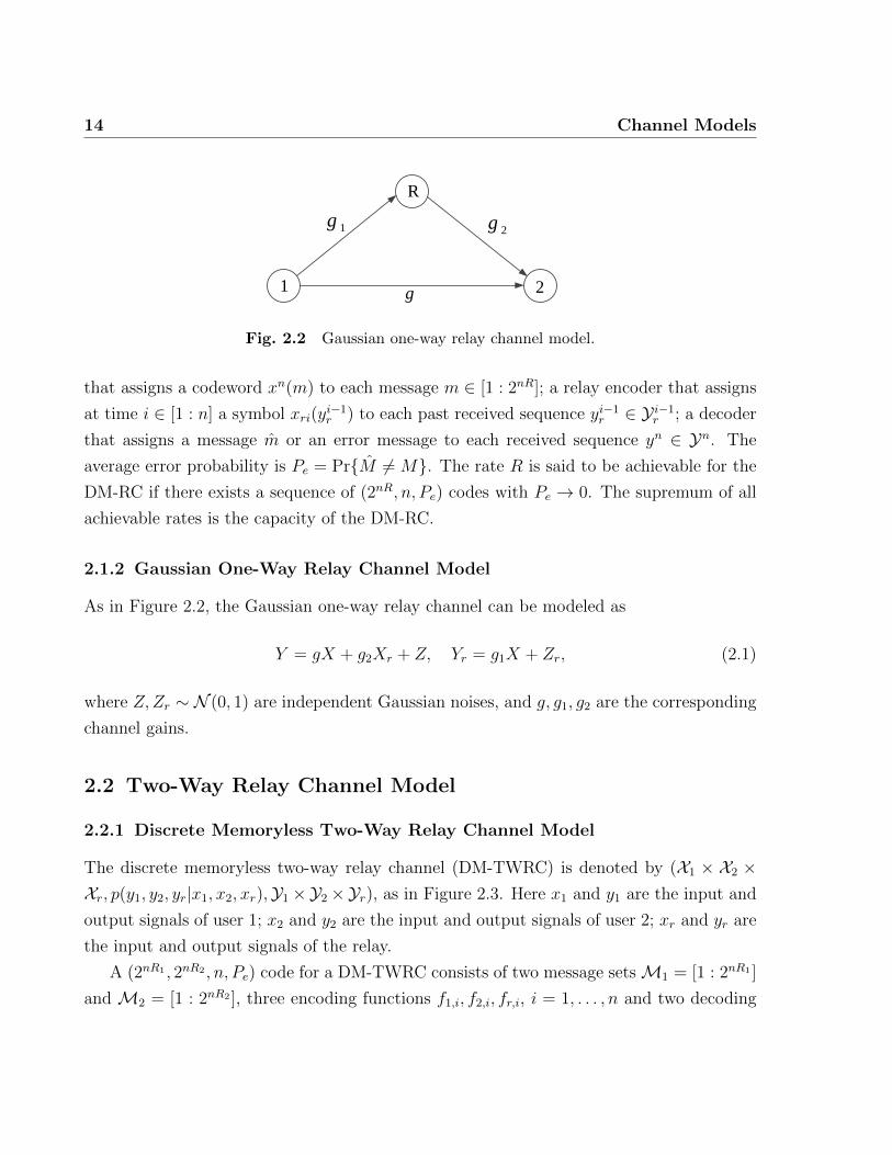
Fig. 2.2 Gaussian one-way relay channel model.
that assigns a codeword xn(m) to each message m ∈ [1 : 2nR]; a relay encoder that assigns
at time i ∈ [1 : n] a symbol xri(yi−1r ) to each past received sequence yi−1r ∈ Y i−1r ; a decoder
that assigns a message m or an error message to each received sequence yn ∈ Yn. The
average error probability is Pe = Pr{M 6= M}. The rate R is said to be achievable for the
DM-RC if there exists a sequence of (2nR, n, Pe) codes with Pe → 0. The supremum of all
achievable rates is the capacity of the DM-RC.
2.1.2 Gaussian One-Way Relay Channel Model
As in Figure 2.2, the Gaussian one-way relay channel can be modeled as
Y = gX + g2Xr + Z, Yr = g1X + Zr, (2.1)
where Z,Zr ∼ N (0, 1) are independent Gaussian noises, and g, g1, g2 are the corresponding
channel gains.
2.2 Two-Way Relay Channel Model
2.2.1 Discrete Memoryless Two-Way Relay Channel Model
The discrete memoryless two-way relay channel (DM-TWRC) is denoted by (X1 × X2 ×Xr, p(y1, y2, yr|x1, x2, xr),Y1×Y2×Yr), as in Figure 2.3. Here x1 and y1 are the input and
output signals of user 1; x2 and y2 are the input and output signals of user 2; xr and yr are
the input and output signals of the relay.
A (2nR1 , 2nR2 , n, Pe) code for a DM-TWRC consists of two message setsM1 = [1 : 2nR1 ]
and M2 = [1 : 2nR2 ], three encoding functions f1,i, f2,i, fr,i, i = 1, . . . , n and two decoding

2.2 Two-Way Relay Channel Model 15
Fig. 2.3 Discrete memoryless two-way relay channel model.
function g1, g2 as follows:
x1,i = f1,i(M1, Y1,1, . . . , Y1,i−1), i = 1, . . . , n
x2,i = f2,i(M2, Y2,1, . . . , Y2,i−1), i = 1, . . . , n
xr,i = fr,i(Yr,1, . . . , Yr,i−1), i = 1, . . . , n
g1 : Yn1 ×M1 →M2
g2 : Yn2 ×M2 →M1
The average error probability is Pe = Pr{g1(M1, Yn1 ) 6= M2 or g2(M2, Y
n2 ) 6= M1}. A rate
pair is said to be achievable if there exists a (2nR1 , 2nR2 , n, Pe) code such that Pe → 0 as
n→∞. The closure of the set of all achievable rates (R1, R2) is the capacity region of the
two-way relay channel.
2.2.2 Full-Duplex Gaussian Two-Way Relay Channel Model
For the Gaussian two-way relay channel, we consider two transmission modes: full-duplex
mode and half-duplex mode. In full-duplex transmission, each node can transmit and
receive at the same time; whereas for half-duplex transmission, each node can only either
transmit or receive at each time. We first discuss the full-duplex model, and then discuss
the half-duplex model in next section.
As in Figure 2.4, the full-duplex Gaussian two-way relay channel can be modeled as:
Y1 = g12X2 + g1rXr + Z1
Y2 = g21X1 + g2rXr + Z2
Yr = gr1X1 + gr2X2 + Zr (2.2)

16 Channel Models
Fig. 2.4 Full-duplex Gaussian two-way relay channel model.
where Z1, Z2, Zr ∼ N (0, 1) are independent Gaussian noises. The average input power con-
straints for user 1, user 2 and the relay are all P . g12, g1r, g21, g2r, gr1, gr2 are corresponding
channel gains.
2.2.3 Half-Duplex Gaussian Two-Way Relay Channel Model
For the half-duplex mode, each node can only either send or receive at each time. We
consider a 4-phase half-duplex Gaussian two-way relay model as in Figure 2.5, as motivated
by [7] which shows the best performance out of several protocols.
1 2
R
1 2
R
1 2
R
1 2
R)( 1 Phase 1 )( 2 Phase 2 )( 3 Phase 3 )( 4 Phase 4
Fig. 2.5 Half-duplex Gaussian two-way relay channel model.
During the 1st phase, user 1 transmits. During the 2nd phase, user 2 transmits. During
the 3rd phase, both user 1 and user 2 transmit. During the 4th phase, the relay transmits.
Assume all nodes listen while not transmitting. The transmitted signals during each phase
can be expressed as
Phase 1: Y21 = g21X11 + Z21, Yr1 = gr1X11 + Zr1
Phase 2: Y12 = g12X22 + Z12, Yr2 = gr2X22 + Zr2
2.3 Relay Networks Model 17
Phase 3: Yr3 = gr1X13 + gr2X23 + Zr2
Phase 4: Y14 = g1rXr + Z14, Y24 = g2rXr + Z24,
where Xij represents the transmitted signal of user i during phase j. Yij represents re-
ceived signal of user i during phase j. All the noises Z are independently and identically
distributed according to N (0, 1).
2.3 Relay Networks Model
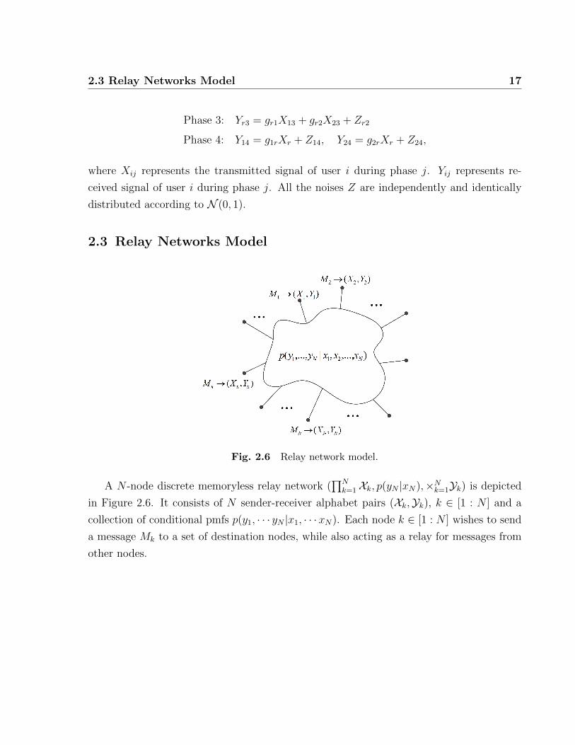
Fig. 2.6 Relay network model.
A N -node discrete memoryless relay network (∏N
k=1Xk, p(yN |xN),×Nk=1Yk) is depicted
in Figure 2.6. It consists of N sender-receiver alphabet pairs (Xk,Yk), k ∈ [1 : N ] and a
collection of conditional pmfs p(y1, · · · yN |x1, · · ·xN). Each node k ∈ [1 : N ] wishes to send
a message Mk to a set of destination nodes, while also acting as a relay for messages from
other nodes.

18

19
Chapter 3
Partial Decode-Forward Coding
Schemes
3.1 Problem Statement
For the one-way relay channel, Cover and El Gamal propose a decode-forward scheme in [1].
The relay fully decodes the message from the source and forwards it to the destination.
However, when the direct link is stronger than the user-to-relay link, decode-forward is not
the optimal scheme compared to direct transmission without using the relay. To combine
both cases, they also design a partial decode-forward scheme where the relay decides to
decode part of the message according to the channel condition.
For the two-way relay channel, there are also two existing coding schemes: direct trans-
mission and full decode-forward scheme. For direct transmission, the relay is not used. For
full decode-forward, the relay decodes the whole message of each user then forwards a func-
tion of these messages as in [2] [3]. As we will see, similarly to the one-way relay channel,
direct transmission achieves strictly larger rate region than decode-forward if for both users,
the direct link is stronger than the user-to-relay link. If for both users, the user-to-relay
link is sufficiently stronger than the direct link, then decode-forward outperforms direct
transmission. However, in cases such that for one user, the user-to-relay link is stronger
than the direct link, while for the other user, it’s the opposite, then neither existing scheme
outperforms the other. This motivates us to put forward the partial decode-forward scheme
where the relay only decodes a part of the messages and forwards them. We propose partial
20 Partial Decode-Forward Coding Schemes
decode-forward for both full- and half-duplex two-way relay channels.
3.2 Partial DF for Full-Duplex TWRC
3.2.1 Coding Scheme and Achievable Rate Region for the DM TWRC
In this section, we provide an achievable rate region for the full-duplex TWRC with a partial
decode-forward scheme. Each user splits its message into two parts and uses superposition
coding to encode them. The relay only decodes one message part of each user and re-encode
the decoded message pair together and broadcast. It can either re-encode each message
pair separately or divides these message pairs into lists and only encodes the list index,
which is similar to the binning technique in [3]. Both strategies achieve the same rate
region. The users then decode the message from each other by joint typicality decoding of
both the current and previous blocks.
Theorem 1. The following rate region is achievable for the two-way relay channel with
partial decode-forward:
R1 ≤ min{I(U1;Yr|U2, Xr) + I(X1;Y2|U1, X2, Xr), I(X1, Xr;Y2|X2)}
R2 ≤ min{I(U2;Yr|U1, Xr) + I(X2;Y1|U2, X1, Xr), I(X2, Xr;Y1|X1)}
R1 +R2 ≤ I(U1, U2;Yr|Xr) + I(X1;Y2|U1, X2, Xr) + I(X2;Y1|U2, X1, Xr) (3.1)
for some joint distribution p(u1, x1)p(u2, x2)p(xr).
Proof. We use a block coding scheme in which each user sends b−1 messages over b blocks
of n symbols each.
1) Codebook generation: Fix p(u1, x1)p(u2, x2)p(xr). Split each message into two parts:
m1 = (m10,m11) with rate (R10, R11), and m2 = (m20,m22) with rate (R20, R22).
• Generate 2nR10 i.i.d. sequences un1 (m10) ∼∏n
i=1 p(u1i), where m10 ∈ [1 : 2nR10 ]. For
each un1 (m10), generate 2nR11 i.i.d. sequences xn1 (m11,m10) ∼∏n
i=1 p(x1i|u1i), where
m11 ∈ [1 : 2nR11 ].
• Generate 2nR20 i.i.d. sequences un2 (m20) ∼∏n
i=1 p(u2i), where m20 ∈ [1 : 2nR20 ]. For
each un2 (m20), generate 2nR22 i.i.d. sequences xn2 (m22,m20) ∼∏n
i=1 p(x2i|u2i), where
m22 ∈ [1 : 2nR22 ].

3.2 Partial DF for Full-Duplex TWRC 21
• Uniformly throw each message pair (m10,m20) into 2nRr bins. Let K(m10,m20) denote
the index of bin.
• Generate 2nRr i.i.d. sequences xnr (K) ∼∏n
i=1 p(xri), where K ∈ [1 : 2nRr ]. If Rr =
R10 +R20, there is no need for binning.
The codebook is revealed to all parties.
2) Encoding: In each block j ∈ [1 : b−1], user 1 and user 2 transmit xn1 (m11,j,m10,j) and
xn2 (m22,j,m20,j) respectively. In block b, user 1 and user 2 transmit xn1 (1, 1) and xn2 (1, 1),
respectively.
At the end of block j, the relay has an estimate (m10,j, m20,j) from the decoding proce-
dure. It transmits xnr (K(m10,j, m20,j)) in block j + 1.
3) Decoding: We explain the decoding strategy at the end of block j.
Decoding at the relay: Upon receiving ynr (j), the relay searches for the unique pair
(m10,j, m20,j) such that
(un1 (m10,j), u
n2 (m20,j), y
nr (j), xnr (K(m10,j−1, m20,j−1))
)∈ T nε .
Following the analysis in multiple access channel, the error probability will go to zero as
n→∞ if
R10 ≤ I(U1;Yr|U2, Xr)
R20 ≤ I(U2;Yr|U1, Xr)
R10 +R20 ≤ I(U1, U2;Yr|Xr). (3.2)
Decoding at each user: By block j, user 2 has decoded m1,j−2. At the end of block j, it
searches for a unique message pair (m10,j−1, m11,j−1) such that
(xnr (K(m10,j−1,m20,j−1)), y
n2 (j), xn2,j
)∈ T nε
and(un1 (m10,j−1), x
n1 (m11,j−1, m10,j−1), y
n2 (j − 1), xnr (K(m1,j−2,m2,j−2)), x
n2,j−1
)∈ T nε .

22 Partial Decode-Forward Coding Schemes
Following joint decoding analysis, the error probability will go to zero as n→∞ if
R11 ≤ I(X1;Y2|U1, X2, Xr)
R10 +R11 ≤ I(Xr;Y2|X2) + I(U1, X1;Y2|X2, Xr) = I(X1, Xr;Y2|X2). (3.3)
Similarly, user 1 can decode (m20,j−1,m22,j−1) with error probability goes to zero as
n→∞ if
R22 ≤ I(X2;Y1|U2, X1, Xr)
R20 +R22 ≤ I(X2, Xr;Y1|X1). (3.4)
By applying Fourier-Motzkin Elimination to the inequalities in (3.2)-(3.4), the achiev-
able rates in terms of R1 = R10 + R11 and R2 = R20 + R22 are as given in Theorem
1.
Remark 1. If U1 = X1, U2 = X2, this region reduces to the decode-forward lower bound
in [3]. Therefore, the partial DF scheme contains the DF scheme in [3] as a special case.
3.2.2 Achievable Rate Region Analysis for the Guassian TWRC
Now we apply the proposed partial decode-forward scheme to the full-duplex Gaussian
TWRC in (2.2). Using jointly Gaussian codewords, we can derive an achievable rate region
as follows.
Theorem 2. The following rate region is achievable for the Gaussian two-way relay chan-
nel.
R1 ≤ min
{C
(g2r1αP
g2r1αP + g2r2βP + 1
)+ C(g221αP ), C(g221P + g22rP )
}R2 ≤ min
{C
(g2r2βP
g2r1αP + g2r2βP + 1
)+ C(g212βP ), C(g212P + g21rP )
}R1 +R2 ≤ C
(g2r1αP + g2r2βP
g2r1αP + g2r2βP + 1
)+ C(g221αP ) + C(g212βP ), (3.5)
where 0 ≤ α, β ≤ 1 and C(x) =1
2log(1 + x).

3.2 Partial DF for Full-Duplex TWRC 23
Achievability follows from Theorem 1 by setting X1 = U1 + V1, where U1 ∼ N (0, αP1)
and V1 ∼ N (0, αP1) are independent, and by setting X2 = U2 + V2, where U2 ∼ N (0, βP2)
and V2 ∼ N (0, βP2) are independent.
Now we analyze and compare above rate region achieved by the proposed partial decode-
forward scheme with that achieved by pure decode-forward scheme [3] and direct trans-
mission (without using the relay) for different channel conditions. We first present the
achievable rate region of pure decode-forward scheme and direct transmission.
Theorem 3. [3] The following rate region is achievable for the full-duplex Gaussian
two-way relay channel with pure decode-forward scheme:
R1 ≤ min{C(g2r1P ), C(g221P + g22rP )
}R2 ≤ min
{C(g2r2P ), C(g212P + g21rP )
}R1 +R2 ≤ C(g2r1P + g2r2P ). (3.6)
If the two users only use direct links to exchange message instead of using the relay, the
following rate region is achievable:
R1 ≤ C(g221P )
R2 ≤ C(g212P ). (3.7)
Remark 2. If α = 1, β = 1, the rate region in (3.5) reduces to the decode-forward lower
bound in (3.6). If α = 0, β = 0, the rate region in (3.5) reduces to the direct transmission
lower bound in (3.7). Thus partial decode-forward region always include both decode-
forward and direct transmission regions as special cases.
The following theorem compares the rate region of partial decode-forwards with that of
pure decode-forwards and direct transmission for different channel cases.
Theorem 4. Comparing PDF with pure decode-forward and direct transmission (without
using the relay), we have the following 4 cases:
1) PDF can achieve rates strictly outside the time-shared region of DF and direct transmis-

24 Partial Decode-Forward Coding Schemes
sion if
g2r1 >g221 + min{g221g2r2P, g22r}, g212 > g2r2
or g2r2 >g212 + min{g212g2r1P, g21r}, g221 > g2r1 (3.8)
2) PDF achieves the time-shared region of DF and direct transmission if
g221 < g2r1, g212 < g2r2
C(g221P ) + C(g212P ) > C(g2r1P + g2r2P ) (3.9)
3) PDF achieves the same rate region as pure DF scheme which is strictly larger than direct
transmission if
g221 ≤ g2r1, g212 ≤ g2r2
C(g221P ) + C(g212P ) ≤ C(g2r1P + g2r2P ) (3.10)
4) PDF achieves the same rate region as direct transmission which is strictly larger than
DF if
g221 ≥ g2r1, g212 ≥ g2r2. (3.11)
Proof. See Appendix A.1.
3.2.3 Discussion and Numerical Examples
Discussion
Some intuition for our proposed partial decode-forward (PDF) scheme can be developed as
follows:
• Compared to DF, PDF involves extra superposition encoding which can be easily
implemented in practice. It uses joint decoding similar to DF and hence has similar
decoding complexity.
• When the user-to-relay link is weaker than the direct link, decoding the whole message
at the relay limits the achievable rate. In such a case, partially decoding messages at

3.2 Partial DF for Full-Duplex TWRC 25
0 0.5 1 1.5 2 2.50
0.2
0.4
0.6
0.8
1
1.2
1.4
1.6
1.8
R1
R2
P=10,gr1=2,g1r=1,gr2=0.4,g2r=1,g12=1,g21=1
DFDirect TranPartial DF
Fig. 3.1 Partial decode-forward achieves rates outside the time-shared re-gion of decode-forward and direct transmission in the full-duplex TWRC.
the relay can relax the constraint and achieve a larger rate region.
• Theorem 4 implies that when both direct links are sufficiently weaker than the user-
to-relay links, the relay should fully decode the messages and forward them. When
both direct links are stronger than the user-to-relay links, the relay should not be
used. If for one user, the direct link is stronger than the user-to-relay link, while for
the other one, the direct link is weaker, then the relay should decode only a part of
the message from the former.
• Applicability in wireless channels: In the wireless environment, the channel gains
fluctuate and can easily cover all cases of Theorem 4. Thus it is useful to know
the optimal scheme for each case such that each user can adapt their transmission
according to the channel strength.
Numerical examples
For cases 1 and 2 in Theorem 4, we provide each an example. Figure 3.1 shows an example
in which partial decode-forward achieves rates outside the time-shared region of decode-
forward and direct transmission. Figure 3.2 shows an example where partial decode-forward
achieves the time-shared region of decode-forward and direct transmission. In both cases,
the proposed PDF scheme outperforms pure DF.

26 Partial Decode-Forward Coding Schemes
0 0.5 1 1.5 2 2.50
0.5
1
1.5
2
2.5
R1
R2
P=10,gr1=2,g1r=1,gr2=2,g2r=1,g12=1,g21=1
DF Direct TranPartial DF
Fig. 3.2 Partial decode-forward achieves time-shared region of decode-forward and direct transmission in the full-duplex TWRC.
3.3 Partial DF for Half-Duplex TWRC
In this section, we design a partial decode-forward scheme for the half-duplex case. The
half-duplex mode in which each node can either transmit or receive at each time, is more
practical in wireless systems. Moreover, transmissions are performed in independent blocks
without block Markovity. Each user can decode the message of the other user at the end
of each block without any delay.
Three decode-forward protocols for the half-duplex two-way relay channel have been
proposed in [7]. The first protocol divides each block into 2 phases, in which both users
transmit in the first phase and the relay transmits in the second phase. The second protocol
divides each block into 3 phases, in which user 1 transmits in the first phase, user 2 in the
second phase and the relay in the third phase. The third protocol divides each block into
4 phases, in which user 1 transmits in the first phase, user 2 in the second phase, both
users transmit in the third phase and the relay transmits in the last phase. All nodes listen
while not transmitting. It has been shown that the 4-phase achieves the largest rate region
among these three protocols.
We will only discuss a 4-phase partial decode-forward scheme as it outperforms the
other two. The main difference between our scheme and the scheme in [7] is that the relay
only decodes a part of the messages in our scheme, whereas it decodes the full messages

3.3 Partial DF for Half-Duplex TWRC 27
1 2
R
1 2
R
1 2
R
1 2
R
1 2 3 4
),( 1110 mm ),( 2220 mm 20m10m
)ˆ,ˆ( 2010 mm
Fig. 3.3 Half-duplex partial decode-forward transmission diagram.
in [7]. When a direct link is stronger than the user-to-relay link, the proposed scheme
achieves strictly larger rate region.
3.3.1 Coding Scheme and Achievable Rate Region
Consider the transmission at each block, which is divided into four phases as in Figure
3.3. Each message is divided into two parts for each user. During the 1st phase, user 1
transmits both parts. During the 2nd phase, user 2 transmits both parts. During the 3rd
phase, both users transmit only one part of their messages. At the end of the 3rd phase,
the relay decodes this part of each message based on the received signals from all first three
phases. It then transmits a function of those message parts during the 4th phase. At the
end of the 4th phase, user 1 decodes the message of user 2 based on received signals in the
2nd and 4th phases. Similarly for user 2.
User encoding
Let the relative time duration of the phases are τ1, τ2, τ3 and τ4 respectively, where τ1 +
τ2 + τ3 + τ4 = 1. Let m1 be the message of user 1 to be sent during a specific block. User 1
divides it into two parts (m10,m11) with rate (R10, R11) and encodes m10 and m11 by U1 and
V1 respectively. Then the transmitted signals of user 1 during phase 1 and 3 respectively
are as follows.
X11 =√α11U1(m10) +
√β11V1(m11)
X13 =√α13U1(m10)
where α11, β11, α13 are corresponding power allocations. Similarly, user 2 divides its message
m2 into two parts (m20,m22) with rate (R20, R22) and encodes m20 and m22 by U2 and V2

28 Partial Decode-Forward Coding Schemes
respectively. Its transmitted signals in the 2nd and 3rd phases respectively are
X22 =√α22U2(m20) +
√β22V2(m22)
X23 =√α23U2(m20).
Relay operation
Decoding: At the end of the 3rd phase, the relay decodes the messages parts (m10,m20)
based on received signals from the 1st, 2nd and 3rd phases by joint decoding.
Encoding: The relay then constructs its transmitted signal in the 4th phase as
Xr =√γW (m10,m20)
where W (m10,m20) can be generated as a function (for example, XOR or random binning)
of the codewords for (m10,m20).
In the above signals, U1, V1, U2, V2,W are independent and identically distributed ac-
cording to N (0, 1). The power constraints for the two users and the relay are as follows.
τ1(α11 + β11) + τ3α13 = P
τ2(α22 + β22) + τ3α23 = P
τ4γ = P. (3.12)
User decoding
At the end of phase 4, user 2 uses joint decoding to decode message m1 = (m10,m11)
based on received signals from both the 1st and 4th phases. Similarly, user 1 decodes
m2 = (m20,m22) based on received signals from both the 2nd and 4th phases.
Theorem 5. The following rate region is achievable for the half-duplex Gaussian two-way

3.3 Partial DF for Half-Duplex TWRC 29
relay channel with partial decode-forward scheme.
R10 ≤ τ1C
(g2r1α11
g2r1β11 + 1
)+ τ3C(g2r1α13) = I1 (3.13a)
R20 ≤ τ2C
(g2r2α22
g2r2β21 + 1
)+ τ3C(g2r2α23) = I2 (3.13b)
R11 ≤ τ1C(g221β11) = I3 (3.13c)
R22 ≤ τ2C(g212β22) = I4 (3.13d)
R10 +R20 ≤ τ1C
(g2r1α11
g2r1β11 + 1
)+ τ2C
(g2r2α22
g2r2β21 + 1
)+ τ3C(g2r1α13 + g2r2α23) = I5 (3.13e)
R10 +R11 ≤ τ1C(g221(α11 + β11)) + τ4C(g22rγ) = I6 (3.13f)
R20 +R22 ≤ τ2C(g212(α22 + β22)) + τ4C(g21rγ) = I7 (3.13g)
with power constraints in (3.12), where τ1 + τ2 + τ3 + τ4 = 1 and C(x) = 12
log(1 + x). By
applying Fourier-Motzkin Elimination, the achievable rates in terms of R1 = R10 +R11 and
R2 = R20 +R22 can be expressed as
R1 ≤min{I1 + I3, I6}
R2 ≤min{I2 + I4, I7}
R1 +R2 ≤I3 + I4 + I5. (3.14)
Proof. At the end of the 3rd phase, the relay decodes (m10,m20) based on received signals
from the 1st, 2nd and 3rd phases, which can succeed with high probability if (3.13a), (3.13b)
and (3.13e) are satisfied. During the 4th phase, the relay sends Xr(m10,m20). Based on the
received signals in the 1st phase Y21 and the 4th phase Y41, user 2 can decodem1 = (m10,m11)
with error probability going to zero if (3.13c) and (3.13f) are satisfied. Similarly, user 1 can
decode m2 = (m20,m22) with vanishing error if (3.13d) and (3.13g) are satisfied.
3.3.2 Discussion
Several points can be noted for our proposed PDF scheme as follows:
• For the half-duplex mode, there is no block Markovity. Therefore, encoding and

30 Partial Decode-Forward Coding Schemes
0 1 2 3 4 50
0.2
0.4
0.6
0.8
1
1.2
1.4
1.6
1.8
R1
R2
P=10,gr1=1,g1r=1,gr2=1,g2r=1,g12=0.5,g21=6
DF Direct TranPartial DF
Time−sharing of DFand Direct Tran
Fig. 3.4 Rate region comparison between partial decode-forward, puredecode-forward and direct transmission for the half-duplex Gaussian TWRC.
decoding are simple and can be done within one block, which is also practical.
• The signaling for each user again involves only 2-part superposition coding which can
be easily implemented in practice.
• It is also interesting to find the optimal power allocations and time slot durations to
maximize the achievable rates as these are of directly practical value. These can be
topics of future work.
• Similar to the full-duplex case, partial decode-forward helps when the direct link is
stronger than the user-to-relay link for one user, while is weaker for the other.
• Our proposed half-duplex PDF scheme again includes both the DF scheme in [7] and
direct transmission as special cases.
3.3.3 Numerical Comparison
We numerically compare the achievable rate regions of partial decode-forward, pure decode-
forward [7] and direct transmission. For direct transmission, we divide each block into two
phases, where user 1 transmits in the first phase and user 2 in the second phase. For pure
decode-forward, we include power scaling to satisfy the power constraint (3.12), which is
different from [7] with fixed power. Hence the DF region here is larger than that in [7].
Figure 3.4 shows that the proposed partial decode-forward scheme achieves strictly larger

3.3 Partial DF for Half-Duplex TWRC 31
rate region than the other two schemes with new rates outside the time-shared region of
the other two. This result also agrees with the analysis in Theorem 4 that when the direct
link is stronger than the user-to-relay link for one user but is weaker for the other, then
PDF strictly outperforms the time-sharing of both DF and direct transmission.

32

33
Chapter 4
Compress-Forward Without Binning
4.1 Problem Statement
Recently, Lim, Kim, El Gamal and Chung put forward a noisy network coding scheme [5]
for the general multi-source noisy network. This scheme involves three key new ideas. The
first is message repetition, in which the same message is sent multiple times over consecutive
blocks using independent codebooks. Second, each relay does not use Wyner-Ziv binning
but only compresses its received signal and forwards the compression index directly. Third,
each destination performs simultaneous decoding of the message based on signals received
from all blocks without uniquely decoding the compression indices. Compared to the
original CF, it achieves the same rate for the one-way relay channel and achieves a larger
rate region when applied to multi-source networks such as the two-way relay channel.
However, message repetition in noisy network coding brings an infinite delay. To reduce
the delay and analyze the impact of no Wyner-Ziv binning, we propose a compress-forward
scheme without Wyner-Ziv binning but with joint decoding of two consecutive blocks. We
apply it to the one-way and two-way relay channel, and then extend to the relay network.
To analyze the impact of message repetition, we modify the scheme in which the message
is repeated only once or twice. We compare their achievable rate regions and analyze the
improvements each technique can bring.

34 Compress-Forward Without Binning
4.2 One-Way Relay Channel
4.2.1 Coding Scheme and Achievable Rate
In the original CF scheme [1] [10], the source sends a new message in each block. The relay
forwards the bin index of the description of its received signal. The receiver uses successive
decoding to decode the bin index first, then decode the message from the sender. Here we
analyze a CF scheme in which the relay forwards the index of the description of its received
signal directly without binning while the receiver jointly decodes the index and message at
the same time. We show that CF without binning can achieve same rate as the original
CF scheme with binning.
The encoding and decoding of CF without binning are as follows (also see Table 4.1).
We use a block coding scheme in which each user sends b − 1 messages over b blocks of n
symbols each.
Block . . . j j + 1 . . .
X . . . xn(mj) xn(mj+1) . . .
Yr . . . yr(kj|kj−1) yr(kj+1|kj) . . .
Xr . . . xnr (kj−1) xnr (kj) . . .
Y . . . kj−1, mj−1 kj, mj . . .
Table 4.1 Encoding and decoding of CF without binning for the one-wayrelay channel.
Codebook generation
Fix p(x)p(xr)p(yr|yr, xr). We randomly and independently generate a codebook for each
block j ∈ [1 : b] as follows.
• Independently generate 2nR sequences xn(mj) ∼∏n
i=1 p(xi), where mj ∈ [1 : 2nR].
• Independently generate 2nRr sequences xnr (kj−1) ∼∏n
i=1 p(xri), where kj−1 ∈ [1 :
2nRr ].
• For each kj−1 ∈ [1 : 2nRr ], independently generate 2nRr sequences ynr (kj|kj−1) ∼∏ni=1 p(yri|xri(kj−1)) where kj ∈ [1 : 2nRr ].

4.2 One-Way Relay Channel 35
Encoding
The source transmits xn(mj) in block j. The relay, upon receiving ynr (j), finds an index kj
such that
(ynr (kj|kj−1), ynr (j), xnr (kj−1)) ∈ T (n)ε ,
where T(n)ε denote the strong ε-typical set [11]. Assume that such kj is found, the relay
sends xnr (kj) in block j + 1.
Decoding
Assume the receiver has decoded kj−1 correctly in block j. Then in block j+1, the receiver
finds a unique pair of (mj, kj) such that
(xnr (kj), yn(j + 1)) ∈ T (n)
ε
and (xn(mj), xnr (kj−1), y
nr (kj|kj−1), yn(j)) ∈ T (n)
ε .
Theorem 6. Consider a compress-forward scheme in which the relay does not use Wyner-
Ziv binning but sends the compression index directly and the destination performs joint
decoding of both the message and compression index. The following rate is achievable for
the one-way relay channel:
R ≤ min{I(X,Xr;Y )− I(Yr;Yr|X,Xr, Y ), I(X;Y, Yr|Xr)} (4.1)
subject to
I(Xr;Y ) + I(Yr;X, Y |Xr) ≥ I(Yr;Yr|Xr) (4.2)
for some p(x)p(xr)p(yr|yr, xr)p(y, yr|x, xr).
Proof. See Appendix A.2.

36 Compress-Forward Without Binning
4.2.2 Comparison with Original Compress-Forward Scheme
Theorem 7. Compress-forward without binning in Theorem 6 achieves the same rate as
the original compress-forward scheme for the one-way relay channel, which is:
R ≤ min{I(X,Xr;Y )− I(Yr;Yr|X,Xr, Y ), I(X;Y, Yr|Xr)} (4.3)
for some p(x)p(xr)p(yr|yr, xr)p(y, yr|x, xr).
Proof. To show that the rate region in Theorem 6 is the same as the rate region in Theorem
7, we need to show that constraint (4.2) is redundant. Note that an equivalent characteri-
zation of the rate region in Theorem 7 is as follows [1] [10] [11]:
R ≤ I(X;Y, Yr|Xr) (4.4)
subject to
I(Xr;Y ) ≥ I(Yr;Yr|Xr, Y ) (4.5)
for some p(x)p(xr)p(yr|yr, xr). Therefore, comparing (4.2) with (4.5), we only need to show
that
I(Yr;Yr|Xr, Y ) ≥ I(Yr;Yr|Xr)− I(Yr;X, Y |Xr).
This is true since
I(Yr;Yr|Xr, Y ) = I(Yr;Yr, X|Xr, Y )
= I(X; Yr|Xr, Y ) + I(Yr; Yr|X,Xr, Y )
≥ I(Yr; Yr|X,Xr, Y )
= I(Yr;X, Y, Yr|Xr)− I(Yr;X, Y |Xr)
= I(Yr;Yr|Xr)− I(Yr;X, Y |Xr).
Remark 3. If using successive decoding, the rate achieved by CF without binning is strictly
less than that with binning. Thus joint decoding is crucial for CF without binning.

4.3 Two-Way Relay Channel 37
Remark 4. Joint decoding does not help improve the rate of the original CF with binning.
Remark 5. Binning technique plays a role of allowing successive decoding instead of joint
decoding, thus reduces destination decoding complexity. However, it has no impact on the
achievable rate for the one-way relay channel. This effect on decoding complexity is similar
to that in decode-forward, in which binning allows successive decoding [1] while no binning
requires backward decoding [35].
Remark 6. For the one-way relay channel, CF without binning achieves the same rate
region as GHF [15]. However, GHF differs from CF without binning in that the relay still
performs binning. In the decoding of GHF, the destination first decode the compression
indices into a list, and then use this list to help decode the source message. However, in
CF without binning, the receiver performs joint decoding of the compression index and
message.
Remark 7. An obvious benefit of this short message CF without binning scheme compared
to noisy network coding is short encoding and decoding delay. A few other benefits such
as low modulation complexity and potential MIMO gain are also recognized in [17].
Remark 8. For the one-way relay channel, all the following schemes achieve the same rate:
the original CF, CF without binning (QF), GHF, and noisy network coding. The difference
in achievable rate only appears when applying to a multi-source and multi-destination
network.
4.3 Two-Way Relay Channel
4.3.1 Coding Scheme and Achievable Rate Region
In this section, we extend CF without Wyner-Ziv binning but with joint decoding of both
the message and compression index to the two-way relay channel. We then compare the
achievable rate region with those by the original CF scheme and noisy network coding.
Compared with the original CF [2], CF without binning achieves a strictly larger rate
region when the channel is asymmetric for the two users. Binning and successive decoding
constrains the compression rate to the weaker of the channels from relay to two users.
But without binning, this constraint is relaxed. Compared with noisy network coding, CF
without binning achieves a smaller rate region. In CF without binning, the users need to

38 Compress-Forward Without Binning
Block . . . j j + 1 . . .
X1 . . . xn1 (m1,j) xn1 (m1,j+1) . . .
X2 . . . xn2 (m2,j) xn2 (m2,j+1) . . .
Yr . . . yr(kj|kj−1) yr(kj+1|kj) . . .
Xr . . . xnr (kj−1) xnr (kj) . . .
Y1 . . . kj−1, m2,j−1 kj, m2,j . . .
Y2 . . . kj−1, m1,j−1 kj, m1,j . . .
Table 4.2 Encoding and decoding of CF without binning for the two-wayrelay channel.
decode the compression index precisely, which brings an extra constraint on the compression
rate. However, this precise decoding is not necessary in noisy network coding.
Before presenting the achievable rate region of CF without binning, we outline its
encoding and decoding techniques as follows. In each block, each user sends a new message
using an independently generated codebook. At the end of each block, the relay finds
a description of its received signal from both users. Then it sends the codeword for the
description index at the next block (instead of partitioning the description index into bins
and sending the codeword for the bin index as in the original CF scheme). Each user jointly
decodes the description index and message from the other user based on signals received
in both the current and previous blocks. This decoding technique is different from that in
the original decode-forward scheme, in which each user first decodes the bin index from the
relay, and then decodes the message from the other user.
Specifically, we use a block coding scheme in which each user sends b− 1 messages over
b blocks of n symbols each (also see Table 4.2).
Codebook generation
Fix joint distribution p(x1)p(x2)p(xr)p(yr|xr, yr). Randomly and independently generate a
codebook for each block j ∈ [1 : b]
• Independently generate 2nR1 sequences xn1 (m1,j) ∼∏n
i=1 p(x1i), where m1,j ∈ [1 :
2nR1 ].

4.3 Two-Way Relay Channel 39
• Independently generate 2nR2 sequences xn2 (m2,j) ∼∏n
i=1 p(x2i), where m2,j ∈ [1 :
2nR2 ].
• Independently generate 2nRr sequences xnr (kj−1) ∼∏n
i=1 p(xri), where kj−1 ∈ [1 :
2nRr ].
• For each kj−1 ∈ [1 : 2nRr ], independently generate 2nRr sequences ynr (kj|kj−1) ∼∏ni=1 p(yri|xri(kj−1)), where kj ∈ [1 : 2nRr ].
Encoding
User 1 and user 2 respectively transmit xn1 (m1,j) and xn2 (m2,j) in block j. The relay, upon
receiving ynr (j), finds an index kj such that
(ynr (kj|kj−1), ynr (j), xnr (kj−1)) ∈ T (n)ε .
Assume that such kj is found, the relay sends xnr (kj) in block j + 1.
Decoding
We discuss the decoding at user 1. Assume user 1 has decoded kj−1 correctly in block j.
Then in block j + 1, user 1 finds a unique pair of (m2,j, kj) such that
(xn2 (m2,j), xnr (kj−1), y
nr (kj|kj−1), yn1 (j), xn1 (m1,j)) ∈ T (n)
ε
and (xnr (kj), yn1 (j + 1), xn1 (m1,j+1)) ∈ T (n)
ε . (4.6)
Theorem 8. The following rate region is achievable for the two-way relay channel by using
compress-forward without binning but with joint decoding:
R1 ≤ min{I(X1;Y2, Yr|X2, Xr), I(X1, Xr;Y2|X2)− I(Yr;Yr|X1, X2, Xr, Y2)}
R2 ≤ min{I(X2;Y1, Yr|X1, Xr), I(X2, Xr;Y1|X1)− I(Yr;Yr|X1, X2, Xr, Y1)} (4.7)
subject to
I(Yr;Yr|X1, X2, Xr, Y1) ≤ I(Xr;Y1|X1)
I(Yr;Yr|X1, X2, Xr, Y2) ≤ I(Xr;Y2|X2) (4.8)

40 Compress-Forward Without Binning
for some p(x1)p(x2)p(xr)p(y1, y2, yr|x1, x2, xr)p(yr|xr, yr).
Proof. See Appendix A.3.
4.3.2 Comparison with Original Compress-Forward Scheme
In this section, we first present the rate region achieved by the original CF scheme for the
two way relay channel as in [2]. We then show that CF without binning but with joint
decoding can achieve a larger rate region.
We outline the encoding and decoding techniques of the original CF scheme as follows.
In each block, each user sends a new message using an independently generated codebook.
At the end of each block, the relay finds a description of its received signal from both users.
Then it partitions the description index into equal-size bins and sends the codeword for
the bin index. Each user applies 3-step successive decoding, in which it first decodes the
bin index from the relay, then decodes the compression index within that bin, and at last
decodes the message from the other user.
Theorem 9. [Rankov and Wittneben]. The following rate region is achievable for two-way
relay channel with the original compress-forward scheme:
R1 ≤ I(X1;Y2, Yr|X2, Xr)
R2 ≤ I(X2;Y1, Yr|X1, Xr) (4.9)
subject to
max(I(Yr;Yr|X1, Xr, Y1), I(Yr;Yr|X2, Xr, Y2)) ≤ min(I(Xr;Y1|X1), I(Xr;Y2|X2)) (4.10)
for some p(x1)p(x2)p(xr)p(y1, y2, yr|x1, x2, xr)p(yr|xr, yr).
We present a short proof of this theorem in Appendix A.4 to show the difference from
CF without binning. The proof follows the same lines as in [2], but we also correct an error
in the analysis of [2] as pointed out in Remark 30 in Appendix A.4.
Proof. See Appendix A.4.

4.3 Two-Way Relay Channel 41
Theorem 10. In the two-way relay channel, the rate region achieved by compress-forward
without binning in Theorem 8 is larger than the rate region achieved by the original compress-
forward scheme in Theorem 9 when the channel is asymmetric for the two users. The two
regions may be equal only if the channel is symmetric, that is the following conditions holds:
I(Xr;Y1|X1) = I(Xr;Y2|X2)
I(Yr;Yr|X1, Xr, Y1) = I(Yr;Yr|X2, Xr, Y2). (4.11)
Furthermore, (4.11) is only necessary but may not be sufficient.
Proof. First, we show that the constraint on the compression rate of Theorem 8 is looser
than that of Theorem 9. This is true since from (4.10), we have
I(Xr;Y1|X1) ≥ I(Yr;Yr|X1, Xr, Y1)
= I(Yr;X2, Yr|X1, Xr, Y1)
≥ I(Yr;Yr|X1, X2, Xr, Y1) (4.12)
where (4.12) is the right-hand-side of the first term in (4.8). Similar for the other term.
Next we show that (4.9) and (4.10) imply (4.7). From (4.9), we have
R2 ≤ I(X2;Y1, Yr|X1, Xr)
= I(X2;Y1|X1, Xr) + I(Yr;X2|Y1, X1, Xr)
= I(X2, Xr;Y1|X1)− I(Xr;Y1|X1) + I(Yr;X2|Y1, X1, Xr)
(a)
≤ I(X2, Xr;Y1|X1)− I(Yr;Yr|X1, Xr, Y1) + I(Yr;X2|Y1, X1, Xr)
= I(X2, Xr;Y1|X1)− I(Yr;Yr|X1, X2, Xr, Y1)
where (a) follows from the constraint of (4.10) in Theorem 9. The equality holds when
I(Xr;Y1|X1) = min{I(Xr;Y1|X1), I(Xr;Y2|X2)}
= I(Yr;Yr|X1, Xr, Y1)
= max(I(Yr;Yr|X1, Xr, Y1), I(Yr;Yr|X2, Xr, Y2)).
42 Compress-Forward Without Binning
Similar for R1, the equality holds when
I(Xr;Y2|X2) = min{I(Xr;Y1|X1), I(Xr;Y2|X2)}
= I(Yr;Yr|X2, Xr, Y2)
= max(I(Yr;Yr|X1, Xr, Y1), I(Yr;Yr|X2, Xr, Y2)).
The above analysis shows that at the boundary of the compression rate constraint (4.10),
the rate region of CF without binning (4.7) is equivalent to that of the original CF (4.9).
However, since constraint (4.8) is loser than (4.10), the rate region in Theorem 8 is larger
than that in Theorem 9. Only if condition (4.11) holds, the original CF scheme may achieve
the same rate region as CF without binning; otherwise, its rate region is strictly smaller.
Remark 9. For the two-way relay channel, binning and successive decoding constrains the
compression rate to the weaker of the channels from relay to two users. But without
binning, this constraint is relaxed. Thus CF without binning achieves a larger rate region
than the original CF scheme when then channel is asymmetric for the two users.
4.3.3 Comparison with Noisy Network Coding
In this section, we compare the rate region achieved by CF without binning with that by
noisy network coding [5] for the two way relay channel. The main differences between
these two schemes are as follows. In CF without binning, different messages are sent over
different blocks, but in noisy network coding, the same message is sent in multiple blocks
using independent codebooks. Furthermore, in noisy network coding, each user performs
simultaneous joint decoding of the message based on signals received from all blocks without
uniquely decoding the compression indices (i.e. relaxed joint decoding). But in CF without
binning, each user jointly decodes both the message and compression index precisely based
on signals received from the current and previous blocks.
Theorem 11. [Lim, Kim, El Gamal and Chung]. The following rate region is achievable
for the two-way relay channel with noisy network coding:
R1 ≤ min{I(X1;Y2, Yr|X2, Xr), I(X1, Xr;Y2|X2)− I(Yr;Yr|X1, X2, Xr, Y2)}
R2 ≤ min{I(X2;Y1, Yr|X1, Xr), I(X2, Xr;Y1|X1)− I(Yr;Yr|X1, X2, Xr, Y1)} (4.13)

4.4 Implication for Relay Networks 43
for some p(x1)p(x2)p(xr)p(y1, y2, yr|x1, x2, xr)p(yr|xr, yr).
Comparing Theorem 8 with Theorem 11, we find that the rate constraints (4.7) for R1
and R2 in CF without binning are the same as those in noisy network coding (4.13). How-
ever, CF without binning has an extra constraint on the compression rate (4.8). Therefore,
in general, CF without binning achieves a smaller rate region than noisy network coding.
Remark 10. In noisy network coding, the combination of message repetition and relaxed
joint decoding is necessary in addition to compress-forward without binning to achieve a
better rate region than that in Theorem 8 for the TWRC.
4.4 Implication for Relay Networks
From the discussion for the one-way and two-way relay channels, we can acquire some
implications for the general relay networks. The relay network model is shown in section
2.3. Noisy network coding is proposed for the general relay network in [5]. Three new
ideas are used in noisy network coding. One is no Wyner-Ziv binning in relay operation.
Another is simultaneous joint decoding of the message over all blocks without uniquely
decoding the compression indices. Last is message repetition, in which the same message
is sent in multiple blocks using independent codebooks. Next, we discuss the effect of each
of these ideas separately.
4.4.1 Implication of no Wyner-Ziv Coding
Generalizing from the two-way relay channel, we can conclude that CF without binning
achieves a larger rate region than the original CF scheme for networks with multiple des-
tinations. With binning and successive decoding, the compression rate is constrained by
the weakest link from a relay to a destination, as in (A.24). But with joint decoding of
the message and compression indices, this constraint is more relaxed since each destination
can also use the signals received from other links, including the direct links, to decode
the compression indices and provides relays more freedom to choose the compression rates.
This explains why for the two-way relay channel, the constraint on compression rate in
CF without binning (4.8) is looser than that in the original CF scheme (4.10). Therefore,
with joint decoding, Wyner-Ziv binning is not necessary. No binning also simplifies relay
operation.

44 Compress-Forward Without Binning
Remark 11. Joint decoding of both the message and compression index is crucial for CF
without binning. Without joint decoding, it achieves strictly smaller rate than the original
CF with binning for any network.
4.4.2 Implication of Joint Decoding without Explicitly Decoding Compression
Indices
A difference between CF without binning and noisy network coding comes from the de-
coding of the compression indices. For both schemes, the compression rate at a relay is
lower bounded by the covering lemma. But in noisy network coding, each destination does
not decode the compression indices explicitly, hence there are no additional constraints
on the compression rate. However, in CF without binning, each destination decodes the
compression indices precisely; this decoding places extra upper bounds on the compression
rate, leading to the constraints on compression rate as in (4.8).
The above analysis prompts the question: what if in CF without binning, we also do
not decode the compression index precisely, can we achieve the same rate region as noisy
network coding? The following analysis shows that the answer is negative. Take the two-
way relay channel as an example. In the next few sections, we apply several joint decoding
rules to enlarge the rate region.
Relaxed joint decoding of a single message without decoding the compression
indices uniquely
Using the same codebook generation and encoding as in CF without binning in Section
4.3.1, but we change the decoding rule in (4.6) to as follows. In block j + 1, user 1 finds a
unique m2,j such that
(xn2 (m2,j), xnr (kj−1), y
nr (kj|kj−1), yn1 (j), xn1 (m1,j)) ∈ T (n)
ε
and (xnr (kj), yn1 (j + 1), xn1 (m1,j+1)) ∈ T (n)
ε (4.14)
for some pair of indices (kj−1, kj). With this decoding rule, the error event E3j which
corresponds to wrong compression index only (see Appendix A.3) no longer applies, but
other new error events appear in which kj−1 6= 1 (see the detailed error analysis in Appendix
A.5). With decoding rule (4.14), we have following Corollary:

4.4 Implication for Relay Networks 45
Corollary 1. For the two-way relay channel, the following rate region is achievable by CF
without binning using joint decoding but without decoding the compression index precisely:
R1 ≤ I(X1;Y2, Yr|X2, Xr) (4.15a)
R1 ≤ I(X1, Xr;Y2|X2)− I(Yr;Yr|X1, X2, Xr, Y2) (4.15b)
R1 ≤ I(X1, Xr;Y2|X2)− I(Yr;Yr|X1, X2, Xr, Y2) + I(Xr;Y2|X2)− I(Y ;Y2|Xr) (4.15c)
R2 ≤ I(X2;Y1, Yr|X1, Xr) (4.15d)
R2 ≤ I(X2, Xr;Y1|X1)− I(Yr;Yr|X1, X2, Xr, Y1) (4.15e)
R2 ≤ I(X2, Xr;Y1|X1)− I(Yr;Yr|X1, X2, Xr, Y1) + I(Xr;Y1|X1)− I(Y ;Y1|Xr) (4.15f)
for some p(x1)p(x2)p(xr)p(y1, y2, yr|x1, x2, xr)p(yr|xr, yr).
Proof. See Appendix A.5.
In above rate region, although the new decoding rule (4.14) removes the constraint on
compression rate, it brings two new rate constraints (4.15c) (4.15f). Hence the rate region
in (4.15) is still smaller than that of noisy network coding in (4.13). These two extra rate
constraints come from the block boundary condition when performing joint decoding over
two blocks. Specifically, it corresponds to the error event E7j in Appendix A.5, in which all
the compression indices and message are wrong. The boundary condition results from the
second decoding rule in (4.14) in which not all input and output signals are involved.
Simultaneous joint decoding of all messages without decoding compression in-
dices uniquely
To reduce the boundary effect, we try simultaneous decoding of all messages over all blocks,
again without decoding the compression indices uniquely. We use the same codebook
generation and encoding as in CF without binning in Section 4.3.1, but use a different
decoding rule at the destination. The destination now jointly decodes all messages based
on the signals received in all blocks, without decoding the compression indices explicitly.
Specifically, user 1 now finds a unique tuple (m2,1, . . .m2,j, . . .m2,b−1) at the end of block b

46 Compress-Forward Without Binning
such that
(xn2 (m2,1), xnr (1), ynr (k1|1), yn1 (1), xn1 (m1,1)) ∈ T (n)
ε (4.16a)
(xn2 (m2,2), xnr (k1), y
nr (k2|k1), yn1 (2), xn1 (m1,2)) ∈ T (n)
ε
...
(xn2 (m2,j), xnr (kj−1), y
nr (kj|kj−1), yn1 (j), xn1 (m1,j)) ∈ T (n)
ε
...
(xn2 (m2,b−1), xnr (kb−2), y
nr (kb−1|kb−2), yn1 (b− 1), xn1 (m1,b−1)) ∈ T (n)
ε (4.16b)
(xn2 (1), xnr (kb−1), ynr (kb|kb−1), yn1 (b), xn1 (1)) ∈ T (n)
ε (4.16c)
for some indices (k1, . . . kj, . . . kb−1, kb).
To compare its achievable rate region with noisy network coding, we consider the error
event in which m2,1 and kb are wrong while all other messages and indices are right. This
error event involves the decoded joint distributions from (4.16a) and (4.16c) as follows.
p(x1)p(x2)p(xr)p(y1, yr|x1, xr)
p(x1)p(x2)p(xr)p(yr|xr)p(y1|x1, x2, xr)
By the packing lemma, the probability of the above error event goes to zero as n→∞ if
R2 +Rr ≤ I(X2;Y1, Yr|X1, Xr) + I(Yr;X1, X2, Y1|Xr) (4.17)
Since Rr > I(Yr;Yr|Xr) by the covering lemma [11], we obtain
R2 ≤ I(X2;Y1, Yr|X1, Xr) + I(Yr;X1, X2, Y1|Xr)− I(Yr;Yr|Xr)
= I(X2;Y1, Yr|X1, Xr)− I(Yr;Yr|X1, X2, Xr, Y1) (4.18)
which is tighter than the constraint (4.13) in noisy network coding. Again we see the
boundary effect at the last block when kb is wrong.

4.4 Implication for Relay Networks 47
Simultaneous joint decoding of all messages but ignoring the last compression
index
Since in the last block, each source sends a known message, the last compression index
kb brings no new information. Hence we may choose to omit it in the decoding rule
to see if the rate region can be improved. Specifically, user 1 now finds a unique tuple
(m2,1, . . .m2,j, . . .m2,b−1) at the end of block b such that
(xn2 (m2,1), xnr (1), ynr (k1|1), yn1 (1), xn1 (m1,1)) ∈ T (n)
ε (4.19a)
(xn2 (m2,2), xnr (k1), y
nr (k2|k1), yn1 (2), xn1 (m1,2)) ∈ T (n)
ε
...
(xn2 (m2,j), xnr (kj−1), y
nr (kj|kj−1), yn1 (j), xn1 (m1,j)) ∈ T (n)
ε
...
(xn2 (m2,b−1), xnr (kb−2), y
nr (kb−1|kb−2), yn1 (b− 1), xn1 (m1,b−1)) ∈ T (n)
ε (4.19b)
(xn2 (1), xnr (kb−1), yn1 (b), xn1 (1)) ∈ T (n)
ε (4.19c)
for some indices (k1, . . . kj, . . . kb−1). Note that (4.19c) is the only step that is different from
(4.16c).
To compare its achievable rate region with noisy network coding, we consider the error
event in which m2,1 and kb−1 are wrong while all other messages and indices are right. This
error event involves the decoded joint distributions from (4.19a), (4.19b) and (4.19c) as
follows.
p(x1)p(x2)p(xr)p(y1, yr|x1, xr)
p(x1)p(x2)p(xr)p(yr|xr)p(y1|x1, x2, xr)
p(x1)p(x2)p(xr)p(y1|x1, x2)
By the packing lemma, the probability of the above error event goes to zero as n→∞ if
R2 +Rr ≤ I(X2;Y1, Yr|X1, Xr) + I(Xr;Y1|X1, X2) + I(Yr;X1, X2, Y1|Xr).

48 Compress-Forward Without Binning
Since Rr > I(Yr;Yr|Xr), we obtain
R2 ≤ I(X2;Y1, Yr|X1, Xr) + I(Xr;Y1|X1, X2) + I(Yr;X1, X2, Y1|Xr)− I(Yr;Yr|Xr)
= I(X2;Y1, Yr|X1, Xr) + I(Xr;Y1|X1, X2)− I(Yr;Yr|X1, X2, Xr, Y1) (4.20)
Although rate constraint (4.20) is loser than (4.18), it is still tighter than the rate constraint
of noisy network coding in (4.13) (we can easily check this for the Gaussian TWRC).
Therefore, simultaneous decoding of all messages over all blocks still achieves a smaller
rate region than noisy network coding.
Remark 12. Joint decoding without explicitly decoding the compression indices removes
the constraints on compression rates but still achieves a smaller rate region than noisy
network coding for the general multi-source network.
Remark 13. Simultaneous joint decoding of all messages over all blocks still does not over-
come the block boundary limitation, caused by the last block in which no new messages
but only the compression indices are sent.
Remark 14. In [22], a technique of appending M blocks for transmission of the compres-
sion indices only is proposed to reduce the block boundary effect, but it also reduces the
achievable rate by a non-vanishing amount.
The above analysis leads us to discuss the effect of message repetition, in which the
same message is transmitted over multiple blocks.
4.4.3 Implication of Message Repetition
Message repetition is performed in noisy network coding by sending the same message in
multiple, consecutive blocks using independent codebooks. To understand the effect of
message repetition, we use the same decoding rule as in the previous section (decoding
the message without explicitly decoding the compression indices) and repeat the message
twice. Now each user transmits the same message in every two consecutive blocks. We
compare the achievable rate region of this scheme with those of no message repetition and
of noisy network coding, in which each message is repeated b times and b approaches to
infinity.
Again take the two-way relay channel as an illustrative example. Let each user transmit
the same message in every two blocks using independent codebooks. Decoding is performed

4.4 Implication for Relay Networks 49
Block . . . 2j − 1 2j 2j + 1
X1 . . . xn1,2j−1(m1,j) xn1,2j(m1,j) xn1,2j+1(m1,j+1)
X2 . . . xn2,2j−1(m2,j) xn2,2j(m2,j) xn2,2j+1(m2,j+1)
Yr . . . yr(k2j−1|k2j−2) yr(k2j|k2j−1) yr(k2j+1|k2j)
Xr . . . xnr (k2j−2) xnr (k2j−1) xnr (k2j)
Y1 . . . m2,j−1 for some (k2j−4, k2j−3, k2j−2) – m2,j for some (k2j−2, k2j−1, k2j)
Y2 . . . m1,j−1 for some (k2j−4, k2j−3, k2j−2) – m1,j for some (k2j−2, k2j−1, k2j)
Table 4.3 Encoding and decoding of CF without binning but with twicemessage repetition for the two-way relay channel.
at the end of every two blocks based on signals received from the current and previous two
blocks. Specifically, the codebook generation, encoding and decoding are as follows (also
see Table 4.3). We use a block coding scheme in which each user sends b messages over
2b+ 1 blocks of n symbols each.
Codebook generation
At block l ∈ {2j − 1, 2j}:
• Independently generate 2n2R1 sequences xn1,l(m1,j) ∼∏n
i=1 p(x1i), where m1,j ∈ [1 :
2n2R1 ].
• Independently generate 2n2R2 sequences xn2,l(m2,j) ∼∏n
i=1 p(x2i), where m2,j ∈ [1 :
2n2R2 ].
• Independently generate 2nRr sequences xnr (kl) ∼∏n
i=1 p(xri), where kl ∈ [1 : 2nRr ].
• For each kl ∈ [1 : 2nRr ], independently generate 2nRr sequences ynr (kl+1|kl) ∼∏n
i=1 p(yri|xri(kl)), where kl+1 ∈ [1 : 2nRr ].
Encoding
In blocks 2j − 1 and 2j, user 1 transmits xn1,2j−1(m1,j) and xn1,2j(m1,j) respectively. User 2
transmits xn2,2j−1(m2,j) and xn2,2j(m2,j).
50 Compress-Forward Without Binning
In block j, the relay, upon receiving ynr (j), finds an index kj such that
(ynr (kj|kj−1), ynr (j), xnr (kj−1)) ∈ T (n)ε .
Assume that such kj is found, the relay sends xnr (kj) in block j + 1.
Decoding
We discuss the decoding at user 1. User 1 decodes m2,j at the end of block 2j + 1.
Specifically, it finds a unique m2,j such that
(xn2,2j−1(m2,j), xnr (k2j−2), y
nr (k2j−1|k2j−2), yn1 (2j − 1), xn1,2j−1(m1,j)) ∈ T (n)
ε
(xn2,2j(m2,j), xnr (k2j−1), y
nr (k2j|k2j−1), yn1 (2j), xn1,2j(m1,j)) ∈ T (n)
ε
and (xnr (k2j), yn1 (2j + 1), xn1,2j+1(m1,j+1)) ∈ T (n)
ε (4.21)
for some (k2j−2, k2j−1, k2j).
Corollary 2. For the two-way relay channel, the following rate region is achievable by CF
without binning and without explicitly decoding the compression indices when repeating each
message twice:
R1 ≤ I(X1;Y2, Yr|X2, Xr) (4.22a)
R1 ≤ I(X1, Xr;Y2|X2)− I(Yr;Yr|X1, X2, Xr, Y2) (4.22b)
R1 ≤ I(X1, Xr;Y2|X2)− I(Yr;Yr|X1, X2, Xr, Y2) +1
2[I(Xr;Y2|X2)− I(Y ;Y2|Xr)] (4.22c)
R2 ≤ I(X2;Y1, Yr|X1, Xr) (4.22d)
R2 ≤ I(X2, Xr;Y1|X1)− I(Yr;Yr|X1, X2, Xr, Y1) (4.22e)
R2 ≤ I(X2, Xr;Y1|X1)− I(Yr;Yr|X1, X2, Xr, Y1) +1
2[I(Xr;Y1|X1)− I(Y ;Y1|Xr)] (4.22f)
for some p(x1)p(x2)p(xr)p(y1, y2, yr|x1, x2, xr)p(yr|xr, yr).
Proof. See Appendix A.6.
Comparing the above rate region with that of CF without message repetition in (4.15)
and noisy network coding in (4.13), we find that the extra rate constraints (4.15c) and

4.4 Implication for Relay Networks 51
(4.15f) are relaxed by repeating the message twice. The additional term is divided by 2,
which comes from the error event Er10j in Appendix A.6, in which the message and all
compression indices are wrong. This event also corresponds to a boundary event, but since
decoding rule (4.21) spans more blocks, the boundary effect is lessen.
Thus if we repeat the messages b times, this additional term will be divided by b.
Taking b to infinity as in noisy network coding completely eliminates the additional terms
in (4.22c) and (4.22f). Hence the rate region is increasing with the number of times for
message repetition. To achieve the largest rate region, the message repetition times need to
be infinity. Therefore, noisy network coding has b blocks decoding delay and b is required
to approach infinity.
Remark 15. Message repetition brings more correlation between different blocks. It helps
lessen the boundary effect when increasing the repetition times.
Remark 16. Message repetition is necessary for achieving the noisy network coding rate re-
gion in multi-source networks. Furthermore, the repetition times need to approach infinity.
Remark 17. This result is different from the single-source single-destination result in [22]
which shows backward decoding without message repetition achieves the same rate as noisy
network coding, albeit at an expense of extending the relay forwarding times infinitely
without actually sending a new message. Thus message repetition appears to be essential
in a multi-source network.
Remark 18. Recent result in [23] by Hou and Kramer is different from our conclusion where
they show that short message NNC can achieve the same rate as NNC even for the multi-
source multi-destination network. This is because there are extra K(K−1) blocks (K is the
number of nodes which is fixed for a specific network) via which each node tries to convey
the compression index in the last block (block b) to all other nodes. In their decoding, each
node first reliably recovers the compression index in the last block, and then uses backward
decoding. This broadcasting and decoding of the last block compression index turns out
ot be crucial in removing the boundary effect and achieving the same rate as repeating the
message as in NNC.

52 Compress-Forward Without Binning
4.5 Gaussian Two-Way Relay Channel
In this section, we focus on the Gaussian two-way relay channel. We compare the rate
regions of CF without binning, the original CF and noisy network coding. We also derive
the analytical condition for when CF without binning achieves the same rate region or sum
rate as noisy network coding.
4.5.1 Achievable Rate Region by CF without Binning
In the Gaussian two-way relay channel model, assume
X1 ∼ N (0, P ), X2 ∼ N (0, P ),
Xr ∼ N (0, P ), Z ∼ N (0, σ2), (4.23)
where X1, X2, Xr and Z are independent, and Yr = Yr + Z. Denote
R11(σ2) = C
(g221P +
g2r1P
1 + σ2
)R12(σ
2) = C(g221P + g22rP )− C(1/σ2)
R21(σ2) = C
(g212P +
g2r2P
1 + σ2
)R22(σ
2) = C(g212P + g21rP )− C(1/σ2), (4.24)
where C(x) = 12
log(1 + x). Then we have following rate region using CF without binning.
Theorem 12. The following rate region is achievable for the Gaussian two-way relay chan-
nel using compress-forward without binning:
R1 ≤ min{R11(σ2), R12(σ
2)}
R2 ≤ min{R21(σ2), R22(σ
2)} (4.25)
for some σ2 ≥ max{σ2c1, σ
2c2}, where
σ2c1 = (1 + g221P )/(g22rP )
σ2c2 = (1 + g212P )/(g21rP ), (4.26)

4.5 Gaussian Two-Way Relay Channel 53
and R11(σ2), R12(σ
2), R21(σ2), R22(σ
2) are as defined in (4.24).
Proof. Applying the rate region in Theorem 8 with the signaling in (4.23), we obtain
(4.25).
4.5.2 Rate Region Comparison with the Original CF Scheme
We now compare the rate regions of CF without binning in Theorem 12 and the original
CF in [2] for the Gaussian two-way relay channel. We first present the rate region achieved
by the original CF scheme.
Corollary 3. [Rankov and Wittneben]. The following rate region is achievable for the
Gaussian two-way relay channel using the original compress-forward scheme:
R1 ≤ R11(σ2)
R2 ≤ R21(σ2) (4.27)
for some σ2 ≥ σ2r , where
σ2r = max
{1 + g221P + g2r1P
min{g22r, g21r}P,1 + g212P + g2r2P
min{g22r, g21r}P
}(4.28)
and R11(σ2), R21(σ
2) are as defined in (4.24).
The following result shows the condition for which the original CF achieves the same
rate region as CF without binning.
Theorem 13. The original compress-forward scheme achieves the same rate region as
compress-forward without binning for the Gaussian TWRC if and only if
g1r = g2r
g221 + g2r1 = g212 + g2r2. (4.29)
Otherwise the rate region by the original compress-forward scheme is smaller.
Remark 19. Condition (4.29) for the Gaussian TWRC is both sufficient and necessary, and
hence is stricter than the result for the DMC case in Theorem 10, which is only necessary.

54 Compress-Forward Without Binning
Proof. Note that both R11(σ2), R21(σ
2) in (4.24) are non-increasing and R12(σ2), R22(σ
2)
are non-decreasing. Let σ2e1 be the intersection between R11(σ
2) and R21(σ2) (similar for
σ2e2) as:
R11(σ2e1) = R12(σ
2e1)
R21(σ2e2) = R22(σ
2e2).
Then we can easily show that
σ2e1 = (1 + g221P + g2r1P )/(g22rP )
σ2e2 = (1 + g212P + g2r2P )/(g21rP ). (4.30)
Therefore, min{R11(σ2), R12(σ
2)} is maximized when σ2 = σ2e1, while min{R21(σ
2), R22(σ2)}
is maximized when σ2 = σ2e2. Noting that σ2
r ≥ σ2e1, σ
2r ≥ σ2
e2 and σ2e1 ≥ σ2
c1, σ2e2 ≥ σ2
c2, we
conclude that the rate region in Theorem 12 is the same as that in Corollary 3 if and only
if σ2r = σ2
e1 = σ2e2. From this equality, we obtain the result in Theorem 13.
4.5.3 Rate Region Comparison with Noisy Network Coding
We next compare the rate regions of CF without binning and noisy network coding [5] for
the Gaussian two-way relay channel. We first present the rate region achieved by noisy
network coding.
Corollary 4. [Lim, Kim, El Gamal and Chung]. The following rate region is achievable
for the Gaussian two-way relay channel with noisy network coding:
R1 ≤ min{R11(σ2), R12(σ
2)}
R2 ≤ min{R21(σ2), R22(σ
2)} (4.31)
for some σ2 > 0, where R11(σ2), R12(σ
2), R21(σ2), R22(σ
2) are defined in (4.24).
The following result shows the condition for which CF without binning achieves the
same rate region as noisy network coding.

4.5 Gaussian Two-Way Relay Channel 55
0 0.5 1 1.50
0.2
0.4
0.6
0.8
1
1.2
1.4
R1
R2
CF without binningOriginal CFNoisy network codingCutset bound
Fig. 4.1 Rate regions for P = 20, gr1 = g1r = 2, gr2 = g2r = 0.5, g12 = g21 =0.1.
Theorem 14. Compress-forward without binning achieves the same rate region as noisy
network coding for the Gaussian TWRC if and only if
σ2c1 ≤ σ2
e2
σ2c2 ≤ σ2
e1, (4.32)
where σ2e1, σ
2e2 are defined in (4.30) and σ2
c1, σ2c2 are defined in (4.26). Otherwise, the rate
region by compress-forward without binning is smaller.
Proof. Similar to the proof of Theorem 13, note that both R11(σ2), R21(σ
2) are non-
increasing and R12(σ2), R22(σ
2) are non-decreasing. Also,
R11(σ2e1) = R12(σ
2e1)
R21(σ2e2) = R22(σ
2e2).
Therefore, the constraint in Theorem 12 is redundant if and only if
max{σ2c1, σ
2c2} ≤ min{σ2
e1, σ2e2}. (4.33)
Since σ2c1 ≤ σ2
e1 and σ2c2 ≤ σ2
e2 always hold, the above condition (4.33) is equivalent to
(4.32).

56 Compress-Forward Without Binning
0 0.2 0.4 0.6 0.8 1 1.2 1.40
0.5
1
1.5
2
2.5
3
3.5
R1
R2
CF without binningOriginal CFNoisy network codingCutset bound
Fig. 4.2 Rate regions for P = 20, gr1 = 0.5, g1r = 2, gr2 = 2, g2r = 0.5, g12 =g21 = 0.1.
Remark 20. If condition (4.29) holds, then condition (4.32) also holds. Thus when the
original CF achieves the same rate region as CF without binning, it also achieves the same
rate region as noisy network coding for the Gaussian TWRC.
Figure 4.1 shows an asymmetric channel configuration in which CF without binning
achieves a strictly larger rate region than the original CF scheme, but strictly smaller than
noisy network coding. Figure 4.2 shows a case that CF without binning achieves the same
rate region as noisy network coding and larger than CF with binning.
4.5.4 Sum Rate Comparison with Noisy Network Coding
We notice that in some cases, even though CF without binning achieves smaller rate region
than noisy network coding, it still has the same sum rate. Thus we are interested in the
channel conditions under which CF without binning and noisy network coding achieve the
same sum rate.
Without loss of generality, assume σ2e1 ≥ σ2
e2 as in (4.30). First we analytically derive
the optimal σ2 that maximizes the sum rate of noisy network coding.
Corollary 5. Let σ2N denotes the optimal σ2 that maximizes the sum rate of the Gaussian
4.5 Gaussian Two-Way Relay Channel 57
TWRC using noisy network coding. Define σ2N1 and σ2
N2 as follows:
if σ2e1 ≥ σ2
g ≥ σ2e2, σ
2N1 = σ2
g ;
if σ2g > σ2
e1 or σ2g ≤ 0, σ2
N1 = σ2e1;
if σ2e2 > σ2
g > 0, σ2N1 = σ2
e2; (4.34)
and
if σ2e1 ≥ σ2
g ≥ σ2z1, σ
2N2 = σ2
g ;
if σ2g > σ2
e1 or σ2g ≤ 0, σ2
N2 = σ2e1;
if σ2z1 > σ2
g > 0, σ2N2 = σ2
z1, (4.35)
where
σ2g =
g2r2P + g212P + 1
g2r2P − g212P − 1,
σ2z1 =
1
g221P + g22rP.
Then,
if σ2z1 ≤ σ2
e2, then σ2N = σ2
N1;
if σ2z1 > σ2
e2, then
if R21(σ2e2) ≤ R12(σ
2N2) +R21(σ
2N2), σ
2N = σ2
N2;
if R21(σ2e2) > R12(σ
2N2) +R21(σ
2N2), σ
2N = σ2
e2. (4.36)
Proof. See Appendix A.7.1.
Based on Theorem 12 and Corollary 5, we now obtain the following result on the
conditions for CF without binning to achieve the same sum rate as noisy network coding
for the Gaussian TWRC.
Theorem 15. Compress-forward without binning achieves the same sum rate as noisy
network coding for the Gaussian TWRC if and only if σ2c1 ≤ σ2
N , where σ2c1 is defined in
(4.26) and σ2N is defined in Corollary 5. Otherwise, the sum rate achieved by compress-

58 Compress-Forward Without Binning
0 10 20 30 40 50 600
0.5
1
1.5
2
2.5
3
3.5
4
4.5
Power constraint P
Sum
rat
e
CF without binningOriginal CFNoisy network codingCutset bound
Fig. 4.3 Sum rate for gr1 = g1r = 2, gr2 = g2r = 0.5, g12 = g21 = 0.1.
forward without binning is smaller.
Proof. According to Corollary 5, the sum rate of noisy network coding is maximized when
σ2 = σ2N . According to Theorem 12, for CF without binning, the constraint on σ2 is
σ2 ≥ σ2c1 (since we assume σ2
c1 ≥ σ2c2). Therefore, compress-forward without binning
achieves the same sum rate as noisy network coding if and only if the constraint region
σ2 ≥ σ2c1 contains σ2
N , which is equivalent to σ2c1 ≤ σ2
N .
We can apply the above result to the special case of gr1 = g1r, gr2 = g2r, g21 = g12 as
follows.
Corollary 6. If gr1 = g1r, gr2 = g2r, g21 = g12, then compress-forward without binning
always achieves the same sum rate as noisy network coding.
Proof. See Appendix A.7.2.
Figure 4.3 plots the sum rates for the same channel configurations as in Figure 4.1,
which shows the sum rates of CF without binning and noisy network coding are the same,
even though the rate regions are not.
As confirmed in Figures 4.1, 4.2 and 4.3, CF without binning achieves a larger rate
region and sum rate than the original CF scheme in [2] when the channel is asymmetric for
the two users. CF without binning achieves the same rate region as noisy network coding

4.5 Gaussian Two-Way Relay Channel 59
when (4.32) is satisfied and achieves the same sum rate for a more relaxed condition.
Furthermore, it has less decoding delay which is only 1 instead of b blocks.

60

61
Chapter 5
Combined Decode-Forward and
Layered Noisy Network Coding
5.1 Problem Statement
We have discussed decode-forward in Chapter 3 and noisy network coding in Chapter 4
for relay channels. Under most channel conditions, these two schemes achieve rate regions
which do not include each other. Therefore, we would like to propose a combined scheme
which can include both of them as special cases.
In [19], Ramalingam and Wang propose a superposition NNC scheme for restricted relay
networks, in which source nodes cannot act as relays, by combining decode-forward and
noisy network coding and show some performance improvement over NNC. Their scheme,
however, does not include DF relaying rate because of no block Markov encoding. We will
first improve this scheme so that it could includes DF relaying rate for the one-way relay
channel.
As we have discussed, there are two existing decode-forward schemes [2] [3] for the two-
way relay channel. In [2], block Markovity is used at the source to obtain a coherent gain
at the cost of reducing power at the relay. In [3], the relay uses its whole power to send
their bin index. We could combine these two decode-forward schemes with an improved
NNC scheme termed ”layered noisy network coding” (LNNC) [18], so that to include the
advantages of all schemes.

62 Combined Decode-Forward and Layered Noisy Network Coding
5.2 Combined DF and NNC Scheme for the One-Way Relay
Channel
In this section, we propose a coding scheme combing decode-forward [1] and noisy network
coding [5] for the one-way relay channel. The source splits its message into two parts, a
common and a private message. The common message is different in each block and is
decoded at both the relay and destination as in decode-forward, while the private message
is the same for all blocks and is decoded only at the destination as in noisy network coding.
The source encodes the common message with block Markovity, and then superimposes
the private message on top. The relay decodes the common message at the end of each
block and compresses the rest as in NNC. In the next block, it sends a codeword which
encodes both the compression index and the decoded common message of the previous
block. The destination decodes each common message by forward sliding-window decoding
over two consecutive blocks. Then at the end of all blocks, it decodes the private message
by simultaneous decoding over all blocks. Our proposed scheme includes both DF relaying
and NNC as special cases and outperforms superposition NNC in [19] in that we use block
Markov encoding for the common messages, which provides coherency between source and
relay and improves the transmission rate.
5.2.1 Coding Scheme and Achievable Rate for the DM One-Way Relay
Channel
Theorem 16. 1 The rate R = R10 + R11 is achievable for the one-way relay channel by
combining decode-forward and noisy network coding
R10 ≤ min{I(Yr;U |Ur, Xr), I(U,Ur;Y )}
R11 ≤ min{I(X;Y, Yr|U,Ur, Xr), I(X,Xr;Y |U,Ur)− I(Yr;Yr|Xr, U, Ur, X, Y )} (5.1)
for some joint distribution that factors as
p(ur)p(u|ur)p(x|u, ur)p(xr|ur)p(y, yr|x, xr)p(yr|yr, u, ur, xr). (5.2)
1The result published in [34] contains an error and it should be corrected as in this theorem. See Remark21 for details.

5.2 Combined DF and NNC Scheme for the One-Way Relay Channel 63
Proof. We use a block coding scheme in which each user sends b−1 messages over b blocks
of n symbols each.
1) Codebook generation: Fix a joint distribution as in (5.2). For each block j ∈ [1 : b]:
• Independently generate 2nR10 sequences unr,j(mj−1) ∼∏n
i=1 p(ur,i), where mj−1 ∈ [1 :
2nR10 ].
• For eachmj−1, independently generate 2nR10 sequences unj (mj|mj−1) ∼∏n
i=1 p(ui|ur,i),mj ∈ [1 : 2nR10 ].
• For each (mj−1,mj), independently generate 2nbR11 sequences xnj (m|mj,mj−1) ∼∏ni=1 p(xi| ui, ur,i), m ∈ [1 : 2nbR11 ].
• For eachmj−1, independently generate 2nR sequences xnr,j(kj−1|mj−1) ∼∏n
i=1 p(xr,i|ur,i),kj−1 ∈ [1 : 2nR].
• For each (mj−1,mj, kj−1), independently generate 2nR sequences ynr,j(kj|kj−1,mj−1,mj) ∼∏ni=1 p(yr,i|xr,i, ur,i, ui), kj ∈ [1 : 2nR].
2) Encoding: In block j, the source sends xnj (m|mj,mj−1). Assume that the relay has
successfully found compression index kj−1 and decoded message mj−1 of the previous block,
it then sends xnr,j(kj−1|mj−1).
3) Decoding at the relay: At the end of block j, upon receiving ynr,j, the relay finds a kj
and a unique mj such that
(unr,j(mj−1), unj (mj|mj−1), x
nr,j(kj−1|mj−1), y
nr,j(kj|kj−1,mj−1, mj), y
nr,j) ∈ T (n)
ε , (5.3)
where T(n)ε denotes the strong typical set [11]. By the covering lemma and standard analysis,
Pe → 0 as n→∞ if
R > I(Yr;Yr|U,Ur, Xr) (5.4)
R +R10 ≤ I(Yr; Yr, U |Ur, Xr). (5.5)
4) Decoding at the destination: At the end of each block j, the destination finds the
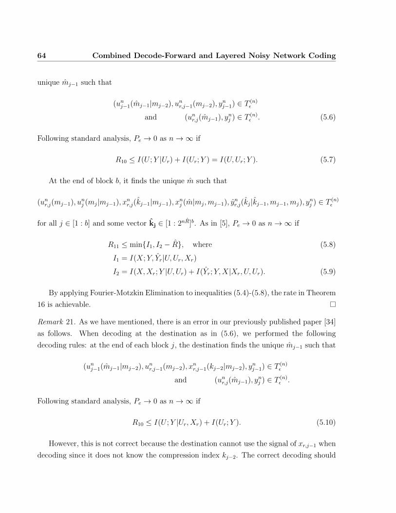
64 Combined Decode-Forward and Layered Noisy Network Coding
unique mj−1 such that
(unj−1(mj−1|mj−2), unr,j−1(mj−2), y
nj−1) ∈ T (n)
ε
and (unr,j(mj−1), ynj ) ∈ T (n)
ε . (5.6)
Following standard analysis, Pe → 0 as n→∞ if
R10 ≤ I(U ;Y |Ur) + I(Ur;Y ) = I(U,Ur;Y ). (5.7)
At the end of block b, it finds the unique m such that
(unr,j(mj−1), unj (mj|mj−1), x
nr,j(kj−1|mj−1), x
nj (m|mj,mj−1), y
nr,j(kj|kj−1,mj−1,mj), y
nj ) ∈ T (n)
ε
for all j ∈ [1 : b] and some vector kj ∈ [1 : 2nR]b. As in [5], Pe → 0 as n→∞ if
R11 ≤ min{I1, I2 − R}, where (5.8)
I1 = I(X;Y, Yr|U,Ur, Xr)
I2 = I(X,Xr;Y |U,Ur) + I(Yr;Y,X|Xr, U, Ur). (5.9)
By applying Fourier-Motzkin Elimination to inequalities (5.4)-(5.8), the rate in Theorem
16 is achievable.
Remark 21. As we have mentioned, there is an error in our previously published paper [34]
as follows. When decoding at the destination as in (5.6), we performed the following
decoding rules: at the end of each block j, the destination finds the unique mj−1 such that
(unj−1(mj−1|mj−2), unr,j−1(mj−2), x
nr,j−1(kj−2|mj−2), y
nj−1) ∈ T (n)
ε
and (unr,j(mj−1), ynj ) ∈ T (n)
ε .
Following standard analysis, Pe → 0 as n→∞ if
R10 ≤ I(U ;Y |Ur, Xr) + I(Ur;Y ). (5.10)
However, this is not correct because the destination cannot use the signal of xr,j−1 when
decoding since it does not know the compression index kj−2. The correct decoding should
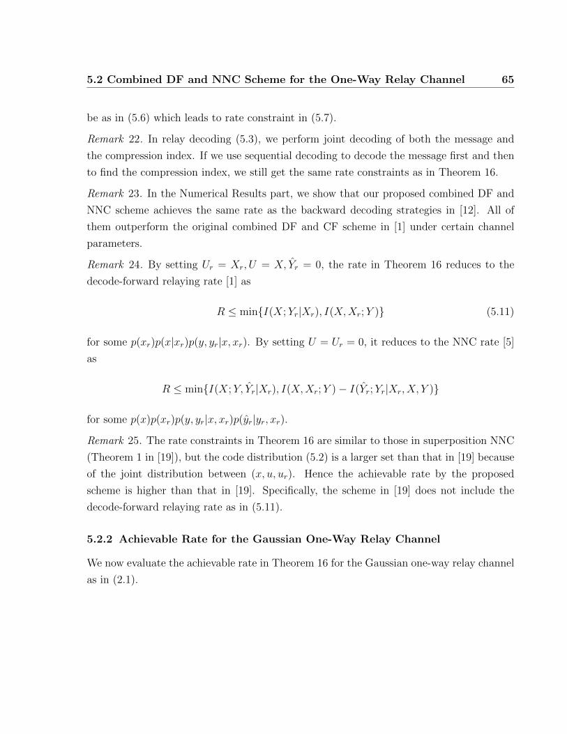
5.2 Combined DF and NNC Scheme for the One-Way Relay Channel 65
be as in (5.6) which leads to rate constraint in (5.7).
Remark 22. In relay decoding (5.3), we perform joint decoding of both the message and
the compression index. If we use sequential decoding to decode the message first and then
to find the compression index, we still get the same rate constraints as in Theorem 16.
Remark 23. In the Numerical Results part, we show that our proposed combined DF and
NNC scheme achieves the same rate as the backward decoding strategies in [12]. All of
them outperform the original combined DF and CF scheme in [1] under certain channel
parameters.
Remark 24. By setting Ur = Xr, U = X, Yr = 0, the rate in Theorem 16 reduces to the
decode-forward relaying rate [1] as
R ≤ min{I(X;Yr|Xr), I(X,Xr;Y )} (5.11)
for some p(xr)p(x|xr)p(y, yr|x, xr). By setting U = Ur = 0, it reduces to the NNC rate [5]
as
R ≤ min{I(X;Y, Yr|Xr), I(X,Xr;Y )− I(Yr;Yr|Xr, X, Y )}
for some p(x)p(xr)p(y, yr|x, xr)p(yr|yr, xr).
Remark 25. The rate constraints in Theorem 16 are similar to those in superposition NNC
(Theorem 1 in [19]), but the code distribution (5.2) is a larger set than that in [19] because
of the joint distribution between (x, u, ur). Hence the achievable rate by the proposed
scheme is higher than that in [19]. Specifically, the scheme in [19] does not include the
decode-forward relaying rate as in (5.11).
5.2.2 Achievable Rate for the Gaussian One-Way Relay Channel
We now evaluate the achievable rate in Theorem 16 for the Gaussian one-way relay channel
as in (2.1).

66 Combined Decode-Forward and Layered Noisy Network Coding
Corollary 7. The following rate is achievable for the Gaussian one-way relay channel
R ≤ min
{C
(g21β
21
g21γ21 + 1
), C
((gα1 + g2α2)
2 + g2β21
g2γ21 + g22β22 + 1
)}+
C
(g2γ21 +
g21γ21 · g22β2
2
g2γ21 + g21γ21 + g22β
22 + 1
)(5.12)
where
α21 + β2
1 + γ21 ≤ P, α22 + β2
2 ≤ P. (5.13)
To achieve the rate in (5.12), we set
U = α1S1 + β1S2, X = U + γ1S3
Xr = α2S1 + β2S4, Yr = Yr + Z ′ (5.14)
where S1, S2, S3, S4 ∼ N (0, 1) and Z ′ ∼ N (0, Q) are independent, and the power allocations
satisfy constraint (5.13).
5.3 Combined DF and LNNC for the Two-Way Relay Channel
In this section, we propose a combined scheme based on both decode-forward strategies
as in [2] [3] and layered noisy network coding [18] for the two-way relay channel. Each
user splits its message into three parts: an independent common, a Markov common and a
private message. The independent and Markov common messages are encoded differently
at the source and are different for each block, both are decoded at both the relay and
destination as in decode-forward. The private message is the same for all blocks and is
decoded only at the destination as in noisy network coding. Each user encodes the Markov
common message with block Markov encoding as in [2], then superimposes the independent
common message on top of it without Markovity, and at last superimposes the private
message on top of both. The relay decodes the two common messages and compresses the
rest into two layers: a common and a refinement layer. In the next block, the relay sends a
codeword which encodes the two decoded common messages and two layered compression
indices. Then at the end of each block, each user decodes two common messages of the
other user by sliding-window decoding over two consecutive blocks. At the end of all blocks,

5.3 Combined DF and LNNC for the Two-Way Relay Channel 67
one user uses the information of the common layer to simultaneously decode the private
message of the other user, while the other user uses the information of both the common
and refinement layers to decode the other user’s private message.
5.3.1 Coding Scheme and Achievable Rate for the DM Two-Way Relay
Channel
Theorem 17. Let R1 denote the set of (R1, R2) as follows:
R1 ≤ min{I5, I12}+ min{I5 − I1, I16}
R2 ≤ min{I6, I14}+ min{I17 − I2, I19}
R1 +R2 ≤ min{min{I5, I12}+ I15 + I18 − I2 + min{I6, I14},
I10 + I15 + I18 − I2,
I10 + min{I15 − I1, I16}+ min{I17 − I2, I19}}
2R1 +R2 ≤ min{I5, I12}+ I15 + I18 − I2 + I10 + min{I15 − I1, I16} (5.15)
for some joint distribution
P ∗ ,p(w1)p(u1|w1)p(v1|w1, u1)p(x1|w1, u1, v1)p(w2)p(u2|w2)p(v2|w2, u2)
p(x2|w2, u2, v2)p(vr|w1, w2)p(ur|vr, w1, w2)p(xr|ur, vr, w1, w2)
p(yr, yr|yr, xr, ur, vr, w1, w2, u1, v1, u2, v2), (5.16)
where Ij are defined in (5.17)-(5.22), then R1 is achievable if user 2 only uses the common
layer, while user 1 uses both the common and refinement layers. If the two users exchange
decoding layers, they can achieve a corresponding set R2. By time sharing, the convex hull
of R1 ∪R2 is achievable.
Proof. We use a block coding scheme in which each user sends b−1 messages over b blocks
of n symbols each.
1) Codebook generation: Fix a joint distribution P ∗ as in (5.16). Each user l ∈ {1, 2}splits its message into three parts: ml0,ml1 and ml2. For each j ∈ [1 : b] and l ∈ {1, 2}
• Independently generate 2nRl0 sequences wnl,j(ml0,j−1) ∼∏n
i=1 p(wl,i), ml0,j−1 ∈ [1 :
2nRl0 ].
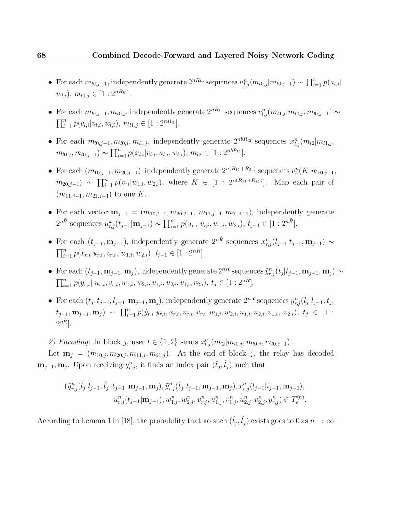
68 Combined Decode-Forward and Layered Noisy Network Coding
• For eachml0,j−1, independently generate 2nRl0 sequences unl,j(ml0,j|ml0,j−1) ∼∏n
i=1 p(ul,i|wl,i), ml0,j ∈ [1 : 2nRl0 ].
• For eachml0,j−1,ml0,j, independently generate 2nRl1 sequences vnl,j(ml1,j|ml0,j,ml0,j−1) ∼∏ni=1 p(vl,i|ul,i, wl,i), ml1,j ∈ [1 : 2nRl1 ].
• For each ml0,j−1,ml0,j,ml1,j, independently generate 2nbRl2 sequences xnl,j(ml2|ml1,j,
ml0,j,ml0,j−1) ∼∏n
i=1 p(xl,i|vl,i, ul,i, wl,i), ml2 ∈ [1 : 2nbRl2 ].
• For each (m10,j−1,m20,j−1), independently generate 2n(R11+R21) sequences vnr (K|m10,j−1,
m20,j−1) ∼∏n
i=1 p(vri|w1,i, w2,i), where K ∈ [1 : 2n(R11+R21)]. Map each pair of
(m11,j−1,m21,j−1) to one K.
• For each vector mj−1 = (m10,j−1,m20,j−1, m11,j−1,m21,j−1), independently generate
2nR sequences unr,j(tj−1|mj−1) ∼∏n
i=1 p(ur,i|vr,i, w1,i, w2,i), tj−1 ∈ [1 : 2nR].
• For each (tj−1,mj−1), independently generate 2nR sequences xnr,j(lj−1|tj−1,mj−1) ∼∏ni=1 p(xr,i|ur,i, vr,i, w1,i, w2,i), lj−1 ∈ [1 : 2nR].
• For each (tj−1,mj−1,mj), independently generate 2nR sequences ynr,j(tj|tj−1,mj−1,mj) ∼∏ni=1 p(yr,i| ur,i, vr,i, w1,i, w2,i, u1,i, u2,i, v1,i, v2,i), tj ∈ [1 : 2nR].
• For each (tj, tj−1, lj−1,mj−1,mj), independently generate 2nR sequences ynr,j(lj|lj−1, tj,tj−1,mj−1,mj) ∼
∏ni=1 p(yr,i|yr,i, xr,i, ur,i, vr,i, w1,i, w2,i, u1,i, u2,i, v1,i, v2,i), tj ∈ [1 :
2nR].
2) Encoding: In block j, user l ∈ {1, 2} sends xnl,j(ml2|ml1,j,ml0,j,ml0,j−1).
Let mj = (m10,j,m20,j,m11,j,m21,j). At the end of block j, the relay has decoded
mj−1,mj. Upon receiving ynr,j, it finds an index pair (tj, lj) such that
(ynr,j(lj|lj−1, tj, tj−1,mj−1,mj), ynr,j(tj|tj−1,mj−1,mj), x
nr,j(lj−1|tj−1,mj−1),
unr,j(tj−1|mj−1), wn1,j, w
n2,j, v
nr,j, u
n1,j, v
n1,j, u
n2,j, v
n2,j, y
nr,j) ∈ T (n)
ε .
According to Lemma 1 in [18], the probability that no such (tj, lj) exists goes to 0 as n→∞

5.3 Combined DF and LNNC for the Two-Way Relay Channel 69
if
R > I(Yr;Xr, Yr|Ur, Vr, U1, V1, U2, V2,W1,W2) , I1 (5.17)
R + R > I(Yr;Xr, Yr|Ur, Vr, U1, V1, U2, V2,W1,W2)+
I(Yr;Yr|Yr, Xr, Ur, Vr, U1, V1, U2, V2,W1,W2) , I2.
The relay then sends xnr,j+1(lj|tj,mj) at block j + 1.
3) Relay decoding: At the end of block j, the relay finds the unique (m10,j, m20,j, m11,j, m21,j)
such that
(wn1,j(m10,j−1), un1,j(m10,j|m10,j−1), v
n1,j(m11,j|m10,j,m10,j−1), w
n2,j(m20,j−1), u
n2,j(m20,j|m20,j−1),
vn2,j(m21,j|m20,j,m20,j−1), vnr,j(m11,j−1,m21,j−1|m10,j−1,m20,j−1), y
nr,j) ∈ T (n)
ε .
As in the multiple access channel, Pe → 0 as n→∞ if
R11 ≤ I(V1;Yr|Vr,W1, U1,W2, U2, V2) , I3
R21 ≤ I(V2;Yr|Vr,W2, U2,W1, U1, V1) , I4
R10 +R11 ≤ I(U1, V1;Yr|Vr,W1,W2, U2, V2) , I5
R20 +R21 ≤ I(U2, V2;Yr|Vr,W2,W1, U1, V1) , I6
R11 +R21 ≤ I(V1, V2;Yr|Vr,W1, U1,W2, U2) , I7
R10 +R11 +R21 ≤ I(U1, V1, V2;Yr|Vr,W1,W2, U2) , I8
R20 +R11 +R21 ≤ I(U2, V1, V2;Yr|Vr,W1,W2, U1) , I9
R10 +R20 +R11 +R21 ≤
(U1, V1, U2, V2;Yr|Vr,W1,W2) , I10. (5.18)
4) User decoding: At the end of block j, user 2 finds the unique (m10,j−1, m11,j−1) such
that
(un1,j−1(m10,j−1|m10,j−2), vn1,j−1(m11,j−1|m10,j−1,m10,j−2),
wn1,j−1, wn2,j−1, u
n2,j−1, v
n2,j−1, x
n2,j−1, v
nr,j−1, y
n2,j−1) ∈ T (n)
ε
and (wn1,j(m10,j−1), wn2,j, u
n2,j, v
n2,j, x
n2,j, v
nr,j(m11,j−1,m21,j−1|m10,j−1,m20,j−1), y
n2,j) ∈ T (n)
ε .

70 Combined Decode-Forward and Layered Noisy Network Coding
The error probability goes to 0 as n→∞ if
R11 ≤ I(V1;Y2|Vr,W1, U1,W2, U2, V2, X2) + I(Vr;Y2|W1,W2, U2, V2, X2) , I11
R10 +R11 ≤ I(U1, V1;Y2|Vr,W1,W2, U2, V2, X2) + I(W1, Vr;Y2|W2, U2, V2, X2)
= I(W1, U1, V1, Vr;Y2|W2, U2, V2, X2) , I12. (5.19)
Similarly, for vanishing-error decoding at user 1
R21 ≤ I(V2;Y1|Vr,W2, U2,W1, U1, V1, X1) + I(Vr;Y1|W2,W1, U1, V1, X1) , I13
R20 +R21 ≤ I(W2, U2, V2, Vr;Y1|W1, U1, V1, X1) , I14. (5.20)
At the end of last block b, user 2 uses one compression layer to find the unique m12 such
that
(xn1,j(m12|m11,j,m10,j,m10,j−1), vn1,j, u
n1,j, w
n1,j, x
n2,j, v
n2,j, u
n2,j,
wn2,j, vnr,j, u
nr,j(tj−1|mj−1), y
nr,j(tj|tj−1,mj−1,mj), y
n2,j) ∈ T (n)
ε
for all j ∈ [1 : b] and some vector tj ∈ [1 : 2nR]b. As in [18], Pe → 0 as n→∞ if
R12 + R ≤ I(X1, Ur;Y2|X2,W1, U1, V1,W2, U2, V2, Vr)+
I(Yr;X1, X2, Y2|Ur,W1, U1, V1,W2, U2, V2, Vr) , I15 (5.21)
R12 ≤ I(X1; Yr, Y2|X2, Ur,W1, U1, V1,W2, U2, V2, Vr) , I16
Using both layers, user 1 finds the unique m22 such that
(xn1,j, vn1,j, u
n1,j, w
n1,j, x
n2,j(m22|m21,j,m20,j,m20,j−1), y
n1,jv
n2,j, u
n2,j, w
n2,jv
nr,j, u
nr,j(tj−1|mj−1),
xnr,j(lj−1|tj−1,mj−1), ynr,j(tj|tj−1,mj−1,mj), y
nr,j(lj|tj, lj−1, tj−1,mj−1,mj)) ∈ T (n)
ε
for all j ∈ [1 : b] and some vectors tj ∈ [1 : 2nR]b, lj ∈ [1 : 2nR]b. As in [18], Pe → 0 as

5.3 Combined DF and LNNC for the Two-Way Relay Channel 71
n→∞ if
R22 + R + R ≤ I(X2, Xr;Y1|X1,W1, U1, V1,W2, U2, V2, Vr)
+ I(Yr;X1, X2, Y1|Yr, Xr, Ur,W1, U1, V1,W2, U2, V2, Vr)
+ I(Yr;X1, X2, Xr, Y2|Ur,W1, U1, V1,W2, U2, V2, Vr) , I17
R22 + R ≤ I(X2, Xr;Y1, Yr|X1, Ur,W1, U1, V1,W2, U2, V2, Vr)
+ I(Yr;X1, X2, Y1|Yr, Xr, Ur,W1, U1, V1,W2, U2, V2, Vr) , I18
R22 ≤ I(X2; Yr, Yr, Y1|X1, Ur, Xr,W1, U1, V1,W2, U2, V2, Vr)
, I19. (5.22)
By applying Fourier-Motzkin Elimination to inequalities (5.17)-(5.22), the rate region
in Theorem 17 is achievable.
Remark 26. By setting V1 = W2 = U2 = V2 = X2 = Ur = Vr = Yr = 0, we obtain the rate
for the one-way channel in Theorem 16 from the region in Theorem 17.
Remark 27. The proposed combined DF-LNNC scheme includes each schemes in [2, 3, 18]
as a special case. Specifically, it reduces to the scheme in [2] by setting U1 = X1, U2 =
X2, Vr = Xr, V1 = V2 = Ur = Yr = Yr = 0, to the scheme in [3] by setting V1 = X1, V2 =
X2, Vr = Xr,W1 = U1 = W2 = U2 = Ur = Yr = Yr = 0, and to the scheme in [18] by setting
W1 = U1 = V1 = W2 = U2 = V2 = Vr = 0.
Remark 28. In our proposed scheme, the Markov common messages bring a coherent gain
between the source and the relay, but they require the relay to split its power for each
message because of block Markov superposition coding. For the independent common
messages, the relay uses its whole power to send the bin index of them which can then solely
represent one message when decoding because of side information on the other message at
each destination.
Remark 29. Rate region for the Gaussian TWRC can be obtained by applying Theorem

72 Combined Decode-Forward and Layered Noisy Network Coding
0 0.2 0.4 0.6 0.8 11.6
1.8
2
2.2
2.4
2.6
2.8
3
3.2
3.4
3.6
Relay location d
Rat
e
DF NNC Superposition NNC DF−NNCCut−set
Fig. 5.1 Achievable rate comparison for the one-way relay channel withP = 10, g1 = d−γ/2, g2 = (1− d)−γ/2, g = 1, γ = 3.
17 with the following signaling:
X1 = α1S1 + β1S2 + γ1S3 + δ1S4
X2 = α2S5 + β2S6 + γ2S7 + δ2S8
Xr = α31S1 + α32S5 + γ3S9 + β3S10 + δ3S11
Yr = Yr + Zr; Yr = Yr + Zr, (5.23)
where the power allocations satisfy
α21 + β2
1 + γ21 + δ21 ≤ P, α22 + β2
2 + γ22 + δ22 ≤ P,
α231 + α2
32 + β23 + γ23 + δ23 ≤ P, (5.24)
all Si ∼ N (0, 1) and Zr ∼ N (0, Q), Zr ∼ N (0, Q) are independent.
5.4 Numerical Results
We numerically compare the performance of the proposed combined schemes with the
original DF and NNC. Consider the Gaussian channels as in (2.1) and (2.2). Assume all
the nodes are on a straight line. The relay is at a distance d from the source and distance
1 − d from the destination which makes g1 = d−γ/2 and g2 = (1 − d)−γ/2, where γ is the
path loss exponent. Figure 5.1 shows the achievable rate for the one-way relay channel with

5.4 Numerical Results 73
d RU R1 R2 R3 R4 R5 R6
0.72 1.9838 1.7061 1.6845 1.7061 1.7061 1.7061 1.7061
0.73 1.9716 1.6881 1.6908 1.6927 1.6984 1.6984 1.6984
0.74 1.9597 1.6703 1.6971 1.6971 1.7012 1.7012 1.7012
0.75 1.9481 1.6529 1.7033 1.7033 1.7052 1.7052 1.7052
0.76 1.9367 1.6538 1.7094 1.7094 1.7099 1.7099 1.7099
0.78 1.9148 1.6022 1.7210 1.7210 1.7210 1.7210 1.7210
Table 5.1 Comparison of achievable rates for P1 = 5, P2 = 1
0 0.1 0.2 0.3 0.4 0.53.5
4
4.5
5
5.5
6
6.5
7
Relay location d
Sum
Rat
e
Indep. DF Markov DF LNNC DF−LNNCCut−set
Fig. 5.2 Sum rate for the two-way relay channel with P = 10, gr1 = g1r =d−γ/2, gr2 = g2r = (1− d)−γ/2, g12 = g21 = 1, γ = 3.
P = 10, γ = 3. The combined DF-NNC scheme supersedes both the DF and NNC schemes.
It can achieve the capacity of the one-way relay channel when the relay is close to either the
source or the destination. Table 5.1 shows the rates for the various schemes, i.e., cut-set
bound (RU), decode-forward (R1), compress-forward (R2), combined DF and CF of Cover
and El Gamal (R3), the SeqBack decoding in [12] (R4), the SimBack decoding strategy
in [12] (R5), the combined DF and NNC (R6). We see that the proposed combined DF and
NNC scheme achieves the same rate as the two backward decoding strategies in [12]. All
of them outperform the generalized combined DF and CF scheme of Cover and El Gamal
in [1] for a certain range of d. Figure 5.2 shows the sum rate for the two-way relay channel
with P = 10, γ = 3. Our proposed scheme achieves larger sum rate than all 3 individual

74 Combined Decode-Forward and Layered Noisy Network Coding
0 0.5 1 1.5 2 2.50
0.5
1
1.5
2
R1
R2
Indep. DF Markov DF LNNC DF−LNNCCut−set
Fig. 5.3 Achievable rate region comparison for the two-way relay channelwith P = 3, gr1 = 6, g1r = 2, gr2 = 2, g2r = 3, g12 = 1, g21 = 0.5.
schemes when the relay is close to either user, while reducing to layered NNC when the
relay is close to the middle of the two users. Figure 5.3 shows the achievable rate regions
for the Gaussian TWRC using these 4 schemes. The achievable region of our proposed
scheme encompasses all 3 individual schemes.

75
Chapter 6
Conclusion and Future Work
6.1 Conclusion
In this thesis, we have proposed and analyzed several coding schemes for the one-way, two-
way relay channels and relay networks. Simulation and analysis show that our proposed
bring improvements on existing schemes, such as decode-forward, compress-forward.
In Chapter 3, we have proposed partial decode-forward (PDF) schemes for both full-
and half-duplex two-way relay channels. Such schemes have not been considered for the
full TWRC (with direct link) before. Each user splits its message into 2 parts and the
relay decodes only one. Analysis and simulation both show that when the direct link
is stronger than the user-to-relay link for one user but is weaker for the other, partial
decode-forward in either full- or half-duplex mode can achieve larger rate region than both
pure decode-forward and direct transmission. Thus, unlike in the one-way Gaussian relay
channel, partial decode-forward is beneficial in the two-way relay channel. Furthermore,
PDF involves only 2-part superposition coding and hence is simple to implement in practice.
In Chapter 4, we have analyzed impacts of the 3 new ideas for compress-forward (CF)
in noisy network coding (NNC): no Wyner-Ziv binning, relaxed simultaneous decoding and
message repetition. For the one-way relay channel (single-source single-destination), no
Wyner-Ziv binning alone without message repetition can achieve the NNC rate at shorter
decoding delay. The extra requirement is joint (but not necessarily relaxed) decoding at
the destination of both the message and compression index. However, for multi-source
multi-destination networks such as the two-way relay channel (TWRC), we find that all 3
techniques together is necessary to achieve the NNC rate region. Under certain channel
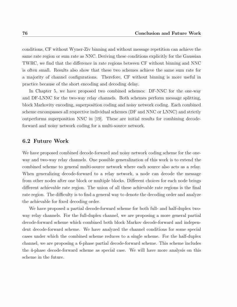
76 Conclusion and Future Work
conditions, CF without Wyner-Ziv binning and without message repetition can achieve the
same rate region or sum rate as NNC. Deriving these conditions explicitly for the Gaussian
TWRC, we find that the difference in rate regions between CF without binning and NNC
is often small. Results also show that these two schemes achieve the same sum rate for
a majority of channel configurations. Therefore, CF without binning is more useful in
practice because of the short encoding and decoding delay.
In Chapter 5, we have proposed two combined schemes: DF-NNC for the one-way
and DF-LNNC for the two-way relay channels. Both schemes perform message splitting,
block Markovity encoding, superposition coding and noisy network coding. Each combined
scheme encompasses all respective individual schemes (DF and NNC or LNNC) and strictly
outperforms superposition NNC in [19]. These are initial results for combining decode-
forward and noisy network coding for a multi-source network.
6.2 Future Work
We have proposed combined decode-forward and noisy network coding scheme for the one-
way and two-way relay channels. One possible generalization of this work is to extend the
combined scheme to general multi-source network where each source also acts as a relay.
When generalizing decode-forward to a relay network, a node can decode the message
from other nodes after one block or multiple blocks. Different choices for each node brings
different achievable rate region. The union of all these achievable rate regions is the final
rate region. The difficulty is to find a general way to denote the decoding order and analyze
the achievable for fixed decoding order.
We have proposed a partial decode-forward scheme for both full- and half-duplex two-
way relay channels. For the full-duplex channel, we are proposing a more general partial
decode-forward scheme which combined both block Markov decode-forward and indepen-
dent decode-forward scheme. We have analyzed the channel conditions for some special
cases under which the combined scheme reduces to a single scheme. For the half-duplex
channel, we are proposing a 6-phase partial decode-forward scheme. This scheme includes
the 4-phase decode-forward scheme as special case. We will have more analysis on this
scheme in the future.

77
Appendix A
Proofs
A.1 Proof of Theorem 4
We prove the first case in Theorem 4. The proofs for other cases are obvious which are
omitted here. According to symmetric, we only need to consider the first part in case 1
which is g2r1 > g221 + min{g221g2r2P, g22r}, g212 > g2r2. This is equivalent to any one of the
following cases is satisfied:
case 1 : C
(g2r1P
g2r2P + 1
)> C(g221P ) (A.1)
case 2 : C(g2r1P ) > C(g221P + g22rP ) (A.2)
We now show that for any of the above two cases, partial decode-forward can achieve rates
outside the the time-shard region of decode-forward and direct transmission.
Case 1: C(
g2r1P
g2r2P+1
)> C(g221P )
We first present an example satisfying the condition of case 1 as shown in Figure A.1.
For point X, Let (R1(X), R2(X)) denote its coordinate. The coordinate of point D is
(R1(D), R2(D)) = (C(g221P ), C(g212P )), which is achieved by direct transmission. With
decode-forward scheme, we can achieve point A with R2(A) = C(g2r2). Since g212 > g2r2,
we have R2(D) > R2(A). Now for the partial decode-forward scheme, set α = 1, β = 0 in

78 Proofs
0 0.5 1 1.5 2 2.50
0.2
0.4
0.6
0.8
1
1.2
1.4
1.6
1.8
R1
R2
P=10,gr1=2,g1r=1,gr2=0.4,g2r=1,g12=1,g21=1
DFDirect TranPartial DF
CD
A
B
Fig. A.1 Example for case 1.
(3.5), we have
R1 ≤ min
{C
(g2r1P
g2r1P + 1
), C(g221P + g22rP )
}R2 ≤ min{C(g212P ), C(g212P + g21rP )} = C(g212P )
R1 +R2 ≤ C
(g2r1P
g2r2P + 1
)+ C(g212P ). (A.3)
Therefore, partial decode-forward can achieve point C with coordinate
(R1(C), R2(C)) =(
min{C(
g2r1P
g2r1P+1
), C(g221P + g22rP )
}, C(g212P )
). Since C
(g2r1P
g2r1P+1
)>
C(g221P ) and C(g221P +g22rP ) > C(g221P ), we have R1(C) > R1(D). Also note that R2(C) =
R2(D) > R2(A). Therefore, point C, achieved by partial decode-forward, is outside the
time-shard region of decode-forward and direct transmission.
Case 2: C(g2r1P ) > C(g221P + g22rP )
We also present an example satisfying the condition of case 2 as shown in Figure A.2.
We show that in this case partial decode-forward can achieve point E which is outside the
time-shared region of decode-forward and direct transmission. Let’s assume
C
(g2r1P
g2r2P + 1
)< C(g221P ); (A.4)

A.1 Proof of Theorem 4 79
0 0.5 1 1.5 2 2.50
0.2
0.4
0.6
0.8
1
1.2
1.4
1.6
1.8
R1
R2
P=10,gr1=2,g1r=1,gr2=0.8,g2r=1,g12=1,g21=1
DFDirect TranPartial DF
A
D
E
B
Fig. A.2 Example for case 2.
otherwise, it will come back to case 1. Define the following items:
I1(β) = C
(g2r1P
g2r2βP + 1
)I2(β) = C
(g2r2βP
g2r2βP + 1
)+ C(g212βP )
I3(β) = C
(g2r1P + g2r2βP
g2r2βP + 1
)+ C(g212βP ) (A.5)
We first show some properties about these three functions. Firstly, for β ∈ [0, 1], we
have
I2(β) = C
(g2r2βP
g2r2βP + 1
)+ C(g212βP )
=1
2log
(g2r2P + 1)(g212βP + 1)
g2r2βP + 1
Since g212 > g2r2, I2(β) is decreasing with the increasing of β. Therefore, I2(β) ≤ I2(0) =
C(g212P ) < C(g212P + g21rP ) for β ∈ [0, 1]. Similarly, I3(β) is decreasing with the increasing
of β for β ∈ [0, 1]. Therefore, I3(β) ≥ I3(1) for β ∈ [0, 1].

80 Proofs
Secondly, for β ∈ [0, 1],
I3(β)− I2(β) = C
(g2r1P + g2r2βP
g2r2βP + 1
)− C
(g2r2βP
g2r2βP + 1
)=
1
2log
g2r1P + g2r2P + 1
g2r2P + 1
= C
(g2r1P
g2r2P + 1
)(a)< C(g221P )
< C(g221P + g22rP ).
where (a) follows from (A.4).
Thirdly, let I1(β) ≥ C(g221P + g22rP ), we have
β ≥ 1 +1
g2r2P
(1− g2r1
g221 + g22r
), β∗ (A.6)
We can show that β∗ ∈ (0, 1).
Now, the rate region in (3.6) achieved by decode-forward can be written as
R1 ≤ min{I1(1), C(g221P + g22rP )
}= C(g221P + g22rP )
R2 ≤ min{I2(1), C(g212P + g21rP )
}= I2(1)
R1 +R2 ≤ I3(1). (A.7)
According to the second property, I3(1) < I2(1) + C(g221P + g22rP ). Therefore, a corner
point B with coordinate (R1(B), R2(B)) = (C(g221P + g22rP ), I3(1) − C(g221P + g22rP )) can
be achieved by decode-forward.
Let α = 1, β = β∗, the rate region in (3.5) achieved by partial decode-forward can be
written as
R1 ≤ min{I1(β
∗), C(g221P + g22rP )}
= C(g221P + g22rP )
R2 ≤ min{I2(β
∗), C(g212P + g21rP )}
= I2(β∗)
R1 +R2 ≤ I3(β∗). (A.8)

A.2 Proof of Theorem 6 81
According to the second property, I3(β∗) < I2(β
∗) + C(g221P + g22rP ). Therefore, a corner
point E with coordinate (R1(E), R2(E)) = (C(g221P + g22rP ), I3(β∗)−C(g221P + g22rP )) can
be achieved by partial decode-forward. Comparing point B with point E, we see that
R1(B) = R1(E), R1(B) < R1(E) with first property. Therefore, point E, achieved by
the partial decode-forward, is outside the time-shard region of decode-forward and direct
transmission.
A.2 Proof of Theorem 6
Assume without loss of generality that mj = 1 and kj−1 = kj = 1. First define the following
two events:
E ′1j(kj) ={
(xnr (kj), yn(j + 1)) ∈ T (n)
ε
}E ′2j(mj, kj) =
{(xn(mj), x
nr (1), ynr (kj|1), yn(j)) ∈ T (n)
ε
}.
Then the decoder makes an error only if one or more of the following events occur:
E1j ={
(ynr (kj|1), ynr (j), xnr (1)) /∈ T (n)ε for all kj ∈ [1 : 2nRr ]
}E2j =
{(xnr (1), yn(j + 1)) /∈ T (n)
ε or (xn(1), xnr (1), ynr (1|1), yn(j)) /∈ T (n)ε
}E3j =
{E ′1j(kj) and E ′2j(1, kj) for some kj 6= 1
}(A.9)
E4j ={E ′1j(1) and E ′2j(mj, 1) for some mj 6= 1
}E5j =
{E ′1j(kj) and E ′2j(mj, kj) for some mj 6= 1, kj 6= 1
}.
Thus, the probability of error is bounded as
P{mj 6= 1, kj 6= 1} ≤ P (E1j) + P (E2j ∩ Ec1j) + P (E3j) + P (E4j) + P (E5j).
By the covering lemma [11], P (E1j)→ 0 as n→∞, if
Rr > I(Yr;Yr|Xr). (A.10)
By the conditional typicality lemma [36], the second term P (E2j ∩ Ec1j)→ 0 as n→∞.
For the rest of the error events, the decoded joint distribution for each event is as

82 Proofs
follows.
E ′1j(kj) : p(xr)p(y)
E ′2j(1, kj) : p(x)p(xr)p(yr|xr)p(y|x, xr)
E ′2j(mj, 1) : p(x)p(xr)p(y, yr|xr)
E ′2j(mj, kj) : p(x)p(xr)p(yr|xr)p(y|xr),
where mj 6= 1, kj 6= 1. Using standard joint typicality analysis with the above decoded
joint distribution, we can obtain a bound on each error event as follows.
Consider E3j:
P (E3j) = P (∪kj 6=1(E ′1j(kj) ∩ E ′2j(1, kj)))
≤∑kj 6=1
P (E ′1j(kj))× P (E ′2j(1, kj)).
Note that if kj 6= 1, then
P (E ′1j(kj)) ≤ 2−n(I(Xr;Y )−δ(ε));
P (E ′2j(1, kj))
=∑
(x,xr,yr,y)∈T (n)ε
p(x)p(xr)p(yr|xr)p(y|x, xr)
≤ 2n(H(X,Xr,Yr,Y )−H(X)−H(Xr)−H(Yr|Xr)−H(Y |X,Xr)−3δ(ε))
= 2n(H(Yr,Y |X,Xr)−H(Yr|Xr)−H(Y |X,Xr)−3δ(ε))
= 2n(H(Yr|Y,X,Xr)−H(Yr|Xr)−3δ(ε))
= 2−n(I(Yr;X,Y |Xr)−3δ(ε)).
Therefore
P (E3j) ≤ 2nRr · 2−n(I(Xr;Y )−δ(ε)) · 2−n(I(Yr;X,Y |Xr)−3δ(ε))
which tends to zero as n→∞ if
Rr ≤ I(Xr;Y ) + I(Yr;X, Y |Xr). (A.11)

A.2 Proof of Theorem 6 83
Next consider E4j:
P (E4j) = P (∪mj 6=1(E ′1j(1) ∩ E ′2j(mj, 1)))
≤∑mj 6=1
P (E ′2j(mj, 1)).
Note that if mj 6= 1, then
P (E ′2j(mj, 1))
=∑
(x,xr,yr,y)∈T (n)ε
p(x)p(xr)p(y, yr|xr)
≤ 2n(H(X,Xr,Yr,Y )−H(X)−H(Xr)−H(Y,Yr|Xr)−2δ(ε))
= 2n(H(Yr,Y |X,Xr)−H(Y,Yr|Xr)−2δ(ε))
= 2−n(I(X;Y,Yr|Xr)−2δ(ε)).
Therefore
P (E4j) ≤2nR · 2−n(I(X;Y,Yr|Xr)−2δ(ε))
which tends to zero as n→∞ if
R ≤ I(X;Y, Yr|Xr). (A.12)
Now consider E5j:
P (E5j) = P (∪mj 6=1 ∪kj 6=1 (E ′1j(kj) ∩ E ′2j(mj, kj)))
≤∑mj 6=1
∑kj 6=1
P (E ′1j(kj))× P (E ′2j(mj, kj)).

84 Proofs
Note that if mj 6= 1 and kj 6= 1, then
P (E ′1j(kj)) ≤ 2−n(I(Xr;Y )−δ(ε));
P (E ′2j(mj, kj))
=∑
(x,xr,yr,y)∈T (n)ε
p(x)p(xr)p(yr|xr)p(y|xr)
≤ 2n(H(X,Xr,Yr,Y )−H(X)−H(Xr)−H(Yr|Xr)−H(Y |Xr)−3δ(ε))
= 2n(H(Yr,Y |X,Xr)−H(Yr|Xr)−H(Y |Xr)−3δ(ε))
= 2n(H(Y |X,Xr)+H(Yr|Y,X,Xr)−H(Yr|Xr)−H(Y |Xr)−3δ(ε))
= 2−n(I(X;Y |Xr)+I(Yr;X,Y |Xr)−3δ(ε)).
Therefore
P (E5j) ≤ 2nR · 2nRr · 2−n(I(Xr;Y )−δ(ε)) · 2−n(I(X;Y |Xr)+I(Yr;X,Y |Xr)−3δ(ε))
which tends to zero as n→∞ if
R +Rr ≤ I(Xr;Y ) + I(X;Y |Xr) + I(Yr;X, Y |Xr)
= I(X,Xr;Y ) + I(Yr;X, Y |Xr). (A.13)
Combining the bounds (A.10) and (A.13), we have
R ≤ I(X,Xr;Y ) + I(Yr;X, Y |Xr)− I(Yr;Yr|Xr)
= I(X,Xr;Y ) + I(Yr;X, Y |Xr)− I(Yr;Yr, X, Y |Xr)
= I(X,Xr;Y )− I(Yr;Yr|X,Xr, Y ). (A.14)
Combining (A.10), (A.11) and (A.12), (A.14), we obtain the result of Theorem 6.

A.3 Proof of Theorem 8 85
A.3 Proof of Theorem 8
Assume without loss of generality that m1,j = m1,j+1 = m2,j = 1 and kj−1 = kj = 1. First
define the following two events:
E ′1j(kj) ={
(xnr (kj), yn1 (j + 1), xn1 (1)) ∈ T (n)
ε
}E ′2j(m2,j, kj) =
{(xn2 (m2,j), x
nr (1), ynr (kj|1), yn1 (j), xn1 (1)) ∈ T (n)
ε
}.
Then the decoder makes an error only if one or more of the following events occur:
E1j ={
(ynr (kj|1), ynr (j), xnr (1)) /∈ T (n)ε for all kj ∈ [1 : 2nRr ]
}E2j =
{(xnr (1), yn1 (j + 1), xn1 (1)) /∈ T (n)
ε or (xn2 (1), xnr (1), ynr (1|1), yn1 (j), xn1 (1)) /∈ T (n)ε
}E3j =
{E ′1j(kj) and E ′2j(1, kj) for some kj 6= 1
}(A.15)
E4j ={E ′1j(1) and E ′2j(m2,j, 1) for some m2,j 6= 1
}E5j =
{E ′1j(kj) and E ′2j(m2,j, kj) for some m2,j 6= 1, kj 6= 1
}.
Thus, the probability of error is bounded as
P{m2,j 6= 1, kj 6= 1} ≤P (E1j) + P (E2j ∩ Ec1j) + P (E3j) + P (E4j) + P (E5j).
By the covering lemma, P (E1j)→ 0 as n→∞, if
Rr > I(Yr;Yr|Xr). (A.16)
By the conditional typicality lemma, the second term P (E2j ∩ Ec1j)→ 0 as n→∞.
For the rest of the error events, the decoded joint distribution for each event is as
follows.
E ′1j(kj) : p(x1)p(xr)p(y1|x1)
E ′2j(1, kj) : p(x1)p(x2)p(xr)p(yr|xr)p(y1|x2, xr, x1)
E ′2j(m2,j, 1) : p(x1)p(x2)p(xr)p(y1, yr|xr, x1)
E ′2j(m2,j, kj) : p(x1)p(x2)p(xr)p(yr|xr)p(y1|xr, x1), (A.17)

86 Proofs
where m2,j 6= 1, kj 6= 1. Using standard joint typicality analysis with the above decoded
joint distribution, we can obtain a bound on each error event as follows.
Consider E3j:
P (E3j) = P (∪kj 6=1(E ′1j(kj) ∩ E ′2j(1, kj)))
≤∑kj 6=1
P (E ′1j(kj))× P (E ′2j(1, kj)).
Note that if kj 6= 1, then
P (E ′1j(kj)) ≤ 2−n(I(Xr;Y1|X1)−δ(ε));
P (E ′2j(1, kj))
=∑
(x1,x2,xr,yr,y1)∈T (n)ε
p(x1)p(x2)p(xr)p(yr|xr)p(y1|x2, xr, x1)
≤ 2n(H(X1,X2,Xr,Yr,Y1)−H(X1)−H(X2)−H(Xr)−H(Yr|Xr)−H(Y1|X2,Xr,X1)−4δ(ε))
= 2n(H(Yr,Y1|X2,Xr,X1)−H(Yr|Xr)−H(Y1|X2,Xr,X1)−4δ(ε))
= 2n(H(Yr|Y1,X2,Xr,X1)−H(Yr|Xr)−4δ(ε))
= 2−n(I(Yr;X1,X2,Y1|Xr)−4δ(ε)).
Therefore
P (E3j) ≤ 2nRr · 2−n(I(Xr;Y1|X1)−δ(ε)) · 2−n(I(Yr;X1,X2,Y1|Xr)−4δ(ε))
which tends to zero as n→∞ if
Rr ≤ I(Xr;Y1|X1) + I(Yr;X1, X2, Y1|Xr). (A.18)
Next consider E4j:
P (E4j) = P (∪m2,j 6=1(E ′1j(1) ∩ E ′2j(m2,j, 1)))
≤∑m2,j 6=1
P (E ′2j(m2,j, 1)).

A.3 Proof of Theorem 8 87
Note that if m2,j 6= 1, then
P (E ′2j(m2,j, 1))
=∑
(x1,x2,xr,yr,y1)∈T (n)ε
p(x1)p(x2)p(xr)p(y1, yr|xr, x1)
≤ 2n(H(X1,X2,Xr,Yr,Y1)−H(X1)−H(X2)−H(Xr)−H(Y1,Yr|Xr,X1)−3δ(ε))
= 2n(H(Yr,Y1|X2,Xr,X1)−H(Y1,Yr|Xr,X1)−3δ(ε))
= 2−n(I(X2;Y1,Yr|Xr,X1)−3δ(ε)).
Therefore
P (E4j) ≤2nR2 · 2−n(I(X2;Y1,Yr|Xr,X1)−3δ(ε))
which tends to zero as n→∞ if
R2 ≤ I(X2;Y1, Yr|Xr, X1). (A.19)
Now consider E5j:
P (E5j) = P (∪m2,j 6=1 ∪kj 6=1 (E ′1j(kj) ∩ E ′2j(m2,j, kj)))
≤∑m2,j 6=1
∑kj 6=1
P (E ′1j(kj))× P (E ′2j(m2,j, kj)).
Note that if m2,j 6= 1 and kj 6= 1, then
P (E ′1j(kj)) ≤ 2−n(I(Xr;Y1|X1)−δ(ε));
P (E ′2j(m2,j, kj))
=∑
(x1,x2,xr,yr,y1)∈T (n)ε
p(x1)p(x2)p(xr)p(yr|xr)p(y1|xr, x1)
≤ 2n(H(X1,X2,Xr,Yr,Y1)−H(X1)−H(X2)−H(Xr)−H(Yr|Xr)−H(Y1|Xr,X1)−4δ(ε))
= 2n(H(Yr,Y1|X2,Xr,X1)−H(Yr|Xr)−H(Y1|Xr,X1)−4δ(ε))
= 2n(H(Y1|X2,Xr,X1)+H(Yr|Y1,X2,Xr,X1)−H(Yr|Xr)−H(Y1|Xr,X1)−4δ(ε))
= 2−n(I(X2;Y1|X1,Xr)+I(Yr;X1,X2,Y1|Xr)−4δ(ε)).

88 Proofs
Therefore
P (E5j) ≤ 2nR2 · 2nRr · 2−n(I(Xr;Y1|X1)−δ(ε)) · 2−n(I(X2;Y1|X1,Xr)+I(Yr;X1,X2,Y1|Xr)−4δ(ε))
which tends to zero as n→∞ if
R2 +Rr ≤ I(Xr;Y1|X1) + I(X2;Y1|X1, Xr) + I(Yr;X1, X2, Y1|Xr)
= I(X2, Xr;Y1|X1) + I(Yr;X1, X2, Y1|Xr). (A.20)
Combining the bounds (A.16) and (A.20), we have
R2 ≤ I(X2, Xr;Y1|X1) + I(Yr;X1, X2, Y1|Xr)− I(Yr;Yr|Xr)
= I(X2, Xr;Y1|X1)− I(Yr;Yr|X1, X2, Xr, Y1). (A.21)
Combining the bounds (A.19) and (A.21), we obtain the rate constraint on R2 in Theorem
8. Similar for R1. From (A.16) and (A.18), we obtain constraint (4.8).
A.4 Proof of Theorem 9
We use a block coding scheme in which each user sends b − 1 messages over b blocks of n
symbols each.
Codebook generation
Fix p(x1)p(x2)p(xr)p(yr|xr, yr). We randomly and independently generate a codebook for
each block j ∈ [1 : b]
• Independently generate 2nR1 sequences xn1 (m1,j) ∼∏n
i=1 p(x1i), where m1,j ∈ [1 :
2nR1 ].
• Independently generate 2nR2 sequences xn2 (m2,j) ∼∏n
i=1 p(x2i), where m2,j ∈ [1 :
2nR2 ].
• Independently generate 2nRr sequences xnr (qj−1) ∼∏n
i=1 p(xri), where qj−1 ∈ [1 :
2nRr ].

A.4 Proof of Theorem 9 89
• For each qj−1 ∈ [1 : 2nRr ], independently generate 2n(Rr+R′r) sequences ynr (qj, rj|qj−1) ∼∏n
i=1 p(yri|xri(qj−1)). Throw them into 2nRr bins, where qj ∈ [1 : 2nRr ] denotes the
bin index and rj ∈ [1 : 2nR′r ] denotes the relative index within a bin.
Encoding
User 1 and user 2 transmits xn1 (m1,j) and xn2 (m2,j) in block j separately. The relay, upon
receiving ynr (j), finds an index pair (qj, rj) such that
(ynr (qj, rj|qj−1), ynr (j), xnr (qj−1)) ∈ T (n)ε .
Assume that such (qj, rj) is found, the relay sends xnr (qj) in block j + 1. By the covering
lemma, the probability that there is no such (qj, rj) tends to 0 as n→∞ if
Rr +R′r > I(Yr;Yr|Xr). (A.22)
Decoding
At the end of block j, user 1 determines the unique qj−1 such that
(xnr (qj−1), yn1 (j), xn1 (m1,j)) ∈ T (n)
ε .
Similar for user 2. Both succeed with high probability if
Rr ≤ min{I(Xr;Y1|X1), I(Xr;Y2|X2)}. (A.23)
Then user 1 uses yn1 (j − 1) to determine the unique rj−1 such that
(ynr (qj−1, rj−1|qj−2), yn1 (j − 1), xnr (qj−2), xn1 (m1,j−1)) ∈ T (n)
ε .
Similar for user 2. Both succeed with high probability if
R′r ≤ min{I(Yr;X1, Y1|Xr), I(Yr;X2, Y2|Xr)}. (A.24)

90 Proofs
Finally, user 1 uses both yn1 (j − 1) and ynr (j − 1) to determine the unique m2,j−1 such that
(xn2 (m2,j−1), ynr (qj−1, rj−1|qj−2), yn1 (j − 1), xnr (qj−2), x
n1 (m1,j−1)) ∈ T (n)
ε .
Similar for user 2. Both succeed with high probability if
R1 ≤ I(X1;Y2, Yr|X2, Xr)
R2 ≤ I(X2;Y1, Yr|X1, Xr). (A.25)
The constraint (4.10) comes from combining (A.22), (A.23) and (A.24).
Remark 30. We note an error in the proof in [2]. In [2], when user 1 determines the unique
rj−1, it is stated that it succeeds with high probability if
R′r ≤ I(Yr;Y1|X1, Xr), (A.26)
which corresponds to step (A.24) in our analysis. However, this is incorrect since the
decoded joint distribution of this error event is p(x1)p(xr)p(yr|xr)p(y1|x1, xr). Therefore,
the error probability can be bounded as
P (E) =∑
(x1,xr,yr,y1)∈T (n)ε
p(x1)p(xr)p(yr|xr)p(y1|x1, xr)
≤ 2n(H(X1,Xr,Yr,Y1)−H(X1)−H(Xr)−H(Yr|Xr)−H(Y1|X1,Xr)−3δ(ε))
= 2−n(I(Yr;X1,Y1|Xr)−3δ(ε)),
which tends to zero as as n→∞ if (A.24) is satisfied instead of (A.26).
A.5 Proof of Corollary 1
The codebook generation and encoding is the same as that in Theorem 8. The decoding
rule is changed as follows: in block j + 1, user 1 finds a unique m2,j such that
(xn2 (m2,j), xnr (kj−1), y
nr (kj|kj−1), yn1 (j), xn1 (m1,j)) ∈ T (n)
ε
and (xnr (kj), yn1 (j + 1), xn1 (m1,j+1)) ∈ T (n)
ε

A.5 Proof of Corollary 1 91
for some pair of (kj−1, kj). Next we present the error analysis.
Assume without loss of generality that m1,j = m1,j+1 = m2,j = 1 and kj−1 = kj = 1.
First define the following two events:
E ′1j(kj) ={
(xnr (kj), yn1 (j + 1), xn1 (1)) ∈ T (n)
ε
}E ′2j(m2,j, kj, kj−1) =
{(xn2 (m2,j), x
nr (kj−1), y
nr (kj|kj−1), yn1 (j), xn1 (1)) ∈ T (n)
ε
}.
Then the decoder makes an error only if one or more of the following events occur:
E1j ={
(ynr (kj|1), ynr (j), xnr (1)) /∈ T (n)ε for all kj ∈ [1 : 2nRr ]
}E2j =
{(xnr (1), yn1 (j + 1), xn1 (1)) /∈ T (n)
ε or (xn2 (1), xnr (1), ynr (1|1), yn1 (j), xn1 (1)) /∈ T (n)ε
}E4j =
{E ′1j(1) and E ′2j(m2,j, 1, 1) for some m2,j 6= 1
}E5j =
{E ′1j(kj) and E ′2j(m2,j, kj, 1) for some m2,j 6= 1, kj 6= 1
}E6j =
{E ′1j(1) and E ′2j(m2,j, 1, kj−1) for some m2,j 6= 1, kj−1 6= 1
}E7j =
{E ′1j(kj) and E ′2j(m2,j, kj, kj−1) for some m2,j 6= 1, kj 6= 1, kj−1 6= 1
},
where E1j, E2j are the same as in (A.15) in the proof of Theorem 8 (Appendix A.3); E3j in
(A.15) is not an error here. E4j and E5j are similar to E4j and E5j in (A.15). E6j and E7jare new error events.
The probability of error is bounded as
P{m2,j 6= 1} ≤ P (E1j) + P (E2j ∩ Ec1j) + P (E4j) + P (E5j) + P (E6j) + P (E7j).
Similar to the proof of Theorem 8 in Appendix A.3, by the covering lemma, P (E1j)→ 0 as
n→∞, if
Rr > I(Yr;Yr|Xr). (A.27)
By the conditional typicality lemma, the second term P (E2j ∩ Ec1j)→ 0 as n→∞.
By the packing lemma, P (E4j)→ 0 as n→∞ if
R2 ≤ I(X2;Y1, Yr|Xr, X1). (A.28)

92 Proofs
Similarly, P (E5j)→ 0 as n→∞ if
R2 +Rr ≤ I(X2, Xr;Y1|X1) + I(Yr;X1, X2, Y1|Xr). (A.29)
For the new error events E6j and E7j, the decoded joint distributions are as follows.
E ′2j(m2,j, 1, kj−1) : p(x1)p(x2)p(xr)p(yr|xr)p(y1|x1)
E ′2j(m2,j, kj, kj−1) : p(x1)p(x2)p(xr)p(yr|xr)p(y1|x1), (A.30)
where m2,j 6= 1, kj 6= 1, kj−1 6= 1. Using standard joint typicality analysis, we can obtain a
bound on each error event as follows. P (E6j)→ 0 as n→∞ if
R2 +Rr ≤ I(X2, Xr;Y1|X1) + I(Yr;X1, X2, Y1|Xr). (A.31)
P (E7j)→ 0 as n→∞ if
R2 + 2Rr ≤ I(Xr;Y1|X1) + I(X2, Xr;Y1|X1) + I(Yr;X1, X2, Y1|Xr). (A.32)
Combining the above inequalities, we obtain the rate region in Corollary 1. Compared to
the rate region of noisy network coding in (4.13), the only new constraint is (A.32), which
occurs when both compression indices are wrong in addition to a wrong message.
A.6 Proof of Corollary 2
Assume without loss of generality that m1,j = m1,j+1 = m2,j = 1 and k2j−2 = k2j−1 = k2j =
1. First define the following three events:
E ′1j(k2j) ={
(xnr (k2j), yn1 (2j + 1), xn1,2j+1(1)) ∈ T (n)
ε
}E ′2j(m2,j, k2j, k2j−1) =
{(xn2,2j(m2,j), x
nr (k2j−1), y
nr (k2j|k2j−1), yn1 (2j), xn1,2j(1)) ∈ T (n)
ε
}E ′3j(m2,j, k2j−1, k2j−2) =
{(xn2,2j−1(m2,j), x
nr (k2j−2), y
nr (k2j−1|k2j−2), yn1 (2j − 1), xn1,2j−1(1)) ∈ T (n)
ε
}.

A.6 Proof of Corollary 2 93
Then the decoder makes an error only if one or more of the following events occur:
E1j ={
(ynr (kj|1), ynr (j), xnr (1)) /∈ T (n)ε for all kj ∈ [1 : 2nRr ]
}E2j =
{(xnr (1), yn1 (2j + 1), xn1,2j+1(1)) /∈ T (n)
ε or
(xn2,2j(1), xnr (1), ynr (1|1), yn1 (2j), xn1,2j(1)) /∈ T (n)ε or
(xn2,2j−1(1), xnr (1), ynr (1|1), yn1 (2j − 1), xn1,2j−1(1)) /∈ T (n)ε
}Er3j =
{E ′1j(1), E ′2j(m2,j, 1, 1) and E ′3j(m2,j, 1, 1) for some m2,j 6= 1
}Er4j =
{E ′1j(1), E ′2j(m2,j, 1, 1) and E ′3j(m2,j, 1, k2j−2) for some m2,j 6= 1, k2j−2 6= 1
}Er5j =
{E ′1j(1), E ′2j(m2,j, 1, k2j−1) and E ′3j(m2,j, k2j−1, 1) for some m2,j 6= 1, k2j−1 6= 1
}Er6j =
{E ′1j(k2j), E ′2j(m2,j, k2j, 1) and E ′3j(m2,j, 1, 1) for some m2,j 6= 1, k2j 6= 1
}Er7j =
{E ′1j(k2j), E ′2j(m2,j, k2j, k2j−1) and E ′3j(m2,j, k2j−1, 1) for some m2,j 6= 1, k2j 6= 1,
k2j−1 6= 1}
Er8j ={E ′1j(k2j), E ′2j(m2,j, k2j, 1) and E ′3j(m2,j, 1, k2j−2) for some m2,j 6= 1, k2j 6= 1, k2j−2 6= 1
}Er9j =
{E ′1j(1), E ′2j(m2,j, 1, k2j−1) and E ′3j(m2,j, k2j−1, k2j−2) for some m2,j 6= 1, k2j−1 6= 1,
k2j−2 6= 1}
Er10j ={E ′1j(k2j), E ′2j(m2,j, k2j, k2j−1) and E ′3j(m2,j, k2j−1, k2j−2)
for some m2,j 6= 1, k2j 6= 1, k2j−1 6= 1, k2j−2 6= 1}
Similar to the proof of Theorem 8 in Appendix A.3, by the covering lemma, P (E1j)→ 0 as
n→∞, if
Rr > I(Yr;Yr|Xr). (A.33)
By the conditional typicality lemma, the second term P (E2j ∩ Ec1j)→ 0 as n→∞.
Let symbol ”∗” represent the wrong message or compression index. For l ∈ {2j, 3j},similar to (A.17) and (A.30), the joint decoded distributions for the rest of the error events

94 Proofs
are as follows.
E ′1j(∗) : p(x1)p(xr)p(y1|x1)
E ′l(∗, 1, 1) : p(x1)p(x2)p(xr)p(y1, yr|xr, x1)
E ′l(∗, 1, ∗) : p(x1)p(x2)p(xr)p(yr|xr)p(y1|x1)
E ′l(∗, ∗, 1) : p(x1)p(x2)p(xr)p(yr|xr)p(y1|xr, x1)
E ′l(∗, ∗, ∗) : p(x1)p(x2)p(xr)p(yr|xr)p(y1|x1).
Using standard joint typicality analysis, we can obtain a bound on each error event as
follows.
P (Er3j)→ 0 as n→∞ if
2R2 ≤ 2I(X2;Y1, Yr|Xr, X1). (A.34)
P (Er4j)→ 0 as n→∞ if
2R2 +Rr ≤ I(X2;Y1, Yr|Xr, X1) + I(X2, Xr;Y1|X1) + I(Yr;X1, X2, Y1|Xr). (A.35)
P (Er5j)→ 0 as n→∞ if
2R2 +Rr ≤ I(X2, Xr;Y1|X1) + I(Yr;X1, X2, Y1|Xr) + I(X2;Y1|X1, Xr) + I(Yr;X1, X2, Y1|Xr).
(A.36)
P (Er6j)→ 0 as n→∞ if
2R2 +Rr ≤ I(X2;Y1, Yr|Xr, X1) + I(X2, Xr;Y1|X1) + I(Yr;X1, X2, Y1|Xr). (A.37)
P (Er7j)→ 0 as n→∞ if
2R2 + 2Rr ≤ I(Xr;Y1|X1) + I(X2, Xr;Y1|X1)
+ I(Yr;X1, X2, Y1|Xr) + I(X2;Y1|X1, Xr) + I(Yr;X1, X2, Y1|Xr). (A.38)

A.7 Proofs of Corollary 5 and Corollary 6 95
P (Er8j)→ 0 as n→∞ if
2R2 + 2Rr ≤ 2[I(X2, Xr;Y1|X1) + I(Yr;X1, X2, Y1|Xr)]. (A.39)
P (Er9j)→ 0 as n→∞ if
2R2 + 2Rr ≤ 2[I(X2, Xr;Y1|X1) + I(Yr;X1, X2, Y1|Xr)]. (A.40)
P (Er10j)→ 0 as n→∞ if
2R2 + 3Rr ≤ I(Xr;Y1|X1) + 2[I(X2, Xr;Y1|X1) + I(Yr;X1, X2, Y1|Xr)]. (A.41)
Combining the above inequalities, we obtain the rate region in Corollary 2. The extra rate
constraints (4.22c) and (4.22f) come only from combing (A.41) with (A.33). Again we see
the boundary effect when the message and all compression indices are wrong.
A.7 Proofs of Corollary 5 and Corollary 6
A.7.1 Proof of Corollary 5
Our objective is to find the optimal σ2 which maximizes the sum rate
s(σ2) , max{
0,min{R11(σ2), R12(σ
2)}}
+ max{
0,min{R21(σ2), R22(σ
2)}}.
Recall that we have assumed σ2e1 ≥ σ2
e2, where σ2e1, σ
2e2 are defined in (4.30). Note that both
R11(σ2), R21(σ
2) are non-increasing and R12(σ2), R22(σ
2) are non-decreasing. Also,
R11(σ2e1) = R12(σ
2e1)
R21(σ2e2) = R22(σ
2e2).
Therefore, the problem of maximizing s(σ2) is equivalent to
max q(σ2) , max{0, R12(σ2)}+R21(σ
2)
s.t. σ2 ≤ σ2e1,
σ2 ≥ σ2e2. (A.42)

96 Proofs
Note that R12(σ2z1) = 0 and R12(σ
2) < 0 for σ2 ∈ (0, σ2z1), R12(σ
2) > 0 for σ2 ∈ (σ2z1,∞).
Therefore, the optimization problem in (A.42) can be derived into the following two cases:
Case 1 : σ2z1 ≤ σ2
e2
In this case, the objective function q(σ2) can be simplified to q(σ2) = R12(σ2) + R21(σ
2),
which is continuously differentiable for σ2 ∈ [σ2e2, σ
2e1]. Thus the optimization problem is
equivalent to
min f(σ2) = −R12(σ2)−R21(σ
2)
s.t. c1(σ2) = σ2
e1 − σ2 ≥ 0,
c2(σ2) = σ2 − σ2
e2 ≥ 0.
Form the Lagrangian as L(σ2, λ1, λ2) = f(σ2) − λ1c1(σ2) − λ2c2(σ
2). With the KKT
conditions, we have:
∇σ2L(σ2N1, λ1, λ2) = 0,
σ2e1 − σ2
N1 ≥ 0,
σ2N1 − σ2
e2 ≥ 0,
λ1, λ2 ≥ 0,
λ1c1(σ2N1) = 0,
λ2c2(σ2N1) = 0. (A.43)
By solving the above conditions, the optimal σ2N1 for this case is characterized as in (4.34).
Case 2 : σ2z1 > σ2
e2
In this case, the objective function q(σ2) is no longer continuously differentiable for σ2 ∈[σ2e2, σ
2e1]. To solve this problem, we divide this interval into two parts. When σ2 ∈ [σ2
e2, σ2z1),
the objective function is simplified to q(σ2) = R21(σ2) and is maximized at σ2 = σ2
e2. When
σ2 ∈ [σ2z1, σ
2e1], the objective function is simplified to q(σ2) = R12(σ
2) + R21(σ2) and is
continuously differentiable for σ2 ∈ [σ2z1, σ
2e1]. With the KKT conditions, the optimal σ2
for this case is characterized as σ2N2 in (4.35). Combining the two intervals, the optimal σ2
N
for this case can be characterized as in (4.36).

A.7 Proofs of Corollary 5 and Corollary 6 97
A.7.2 Proof of Corollary 6
From Corollary 5 and Theorem 15, we have:
If σ2z1 ≤ σ2
e2, then the two schemes achieve the same sum rate if and only if at least one of
the following three conditions holds:
σ2c1 ≤ σ2
e2 (A.44)
0 < σ2c1 ≤ σ2
g (A.45)
σ2g ≤ 0 (A.46)
For the channel configuration of gr1 = g1r, gr2 = g2r, g21 = g12, we can show that either
(A.45) or (A.46) will hold.
If σ2z1 > σ2
e2, we can show that R21(σ2e2) < R12(σ
2e1) +R21(σ
2e1) always holds. Therefore,
according to (4.35) and (4.36), the optimal σ2N can be characterized as:
if σ2e1 ≥ σ2
g ≥ 0, σ2N = σ2
g ;
if σ2g > σ2
e1 or σ2g < 0, σ2
N = σ2e1.
Since either (A.45) or (A.46) holds and σ2c1 ≤ σ2
e1, we obtain σ2c1 ≤ σ2
N . According to
Theorem 15, the two schemes then achieve the same sum rate.

98

99
References
[1] T. Cover and A. El Gamal, “Capacity theorems for the relay channel,” IEEE Trans.
on Info. Theory, vol. 25, no. 5, pp. 572–584, 1979.
[2] B. Rankov and A. Wittneben, “Achievable rate regions for the two-way relay channel,”
in Int’l Symp. on Info. Theory (ISIT). IEEE, 2006, pp. 1668–1672.
[3] L. Xie, “Network coding and random binning for multi-user channels,” in 10th Cana-
dian Workshop on Info. Theory (CWIT). IEEE, 2007, pp. 85–88.
[4] G. Kramer, M. Gastpar, and P. Gupta, “Cooperative strategies and capacity theorems
for relay networks,” IEEE Trans. on Info. Theory, vol. 51, no. 9, pp. 3037–3063, Sept.
2005.
[5] S. H. Lim, Y.-H. Kim, A. El Gamal, and S.-Y. Chung, “Noisy network coding,” IEEE
Trans. on Info. Theory, vol. 57, no. 5, pp. 3132–3152, May 2011.
[6] F. Willems and E. van der Meulen, “The discrete memoryless multiple-access channel
with cribbing encoders,” IEEE Trans. on Info. Theory, vol. 31, no. 3, pp. 313–327,
May 1985.
[7] S. J. Kim, P. Mitran, and V. Tarokh, “Performance bounds for bidirectional coded
cooperation protocols,” IEEE Trans. on Info. Theory, vol. 54, no. 11, pp. 5235 –5241,
Nov. 2008.
[8] S. J. Kim, N. Devroye, P. Mitran, and V. Tarokh, “Achievable rate regions and perfor-
mance comparison of half duplex bi-directional relaying protocols,” IEEE Trans. on
Info. Theory, vol. 57, no. 10, pp. 6405–6418, Oct. 2011.

100 References
[9] A. Wyner and J. Ziv, “The rate-distortion function for source coding with side infor-
mation at the decoder,” IEEE Trans. on Info. Theory, vol. 22, no. 1, pp. 1–10, Jan.
1976.
[10] A. El Gamal, M. Mohseni, and S. Zahedi, “Bounds on capacity and minimum energy-
per-bit for AWGN relay channels,” IEEE Trans. on Info. Theory, vol. 52, no. 4, pp.
1545–1561, April 2006.
[11] A. E. Gamal and Y.-H. Kim, Network information theory. Cambridge University
Press, 2011.
[12] H.-F. Chong, M. Motani, and H. K. Garg, “Generalized backward decoding strategies
for the relay channel,” IEEE Trans. on Info. Theory, vol. 53, no. 1, pp. 394–401, Jan.
2007.
[13] T. M. Cover and Y.-H. Kim, “Capacity of a class of deterministic relay channels,” in
IEEE Int’l Symp. on Info. Theory (ISIT), June 2007, pp. 591–595.
[14] Y.-H. Kim, “Coding techniques for primitive relay channels,” in 45th Annual Allerton
Conf. on Comm., Control, and Computing, Sept. 2007.
[15] P. Razaghi and W. Yu, “Universal relaying for the interference channel,” in Info.
Theory and Applications Workshop (ITA), Feb. 2010.
[16] L. Zhou and W. Yu, “Incremental relaying for the Gaussian interference channel with
a degraded broadcasting relay,” in 49th Annual Allerton Conf. on Comm., Control,
and Computing, Sept. 2011.
[17] G. Kramer and J. Hou, “Short-message quantize-forward network coding,” in 8th Int’l
Workshop on Multi-Carrier Systems Solutions (MC-SS), May 2011, pp. 1–3.
[18] S. H. Lim, Y.-H. Kim, A. El Gamal, and S.-Y. Chung, “Layered noisy network coding,”
in IEEE Wireless Net. Coding Conf. (WiNC), June 2010.
[19] N. Ramalingam and Z. Wang, “Superposition noisy network coding,” in IEEE Int’l
Symp. on Info. Theory (ISIT), Aug. 2011.

References 101
[20] T. Kim, M. Skoglund, and G. Caire, “Quantifying the loss of compress-forward relaying
without Wyner-Ziv coding,” IEEE Trans. on Info. Theory, vol. 55, no. 4, pp. 1529–
1533, April 2009.
[21] X. Wu and L.-L. Xie, “On the optimality of successive decoding in compress-and-
forward relay schemes,” in 48th Annual Allerton Conf. on Comm., Control, and Com-
puting, Oct. 2010.
[22] ——, “On the optimal compressions in the compress-and-forward relay schemes,” Arxiv
preprint arXiv: 1009.5959v3, 2011.
[23] J. Hou and G. Kramer, “Short message noisy network coding for multiple sources,” in
IEEE Int’l Symp. on Info. Theory (ISIT), July 2012.
[24] B. Nazer and M. Gastpar, “Compute-and-forward: Harnessing interference through
structured codes,” Arxiv preprint arXiv:0908.2119, 2009.
[25] U. Erez, S. Litsyn, and R. Zamir, “Lattices which are good for (almost) everything,”
IEEE Trans. on Info. Theory, vol. 51, no. 10, pp. 3401–3416, 2005.
[26] K. Narayanan, M. Wilson, and A. Sprintson, “Joint physical layer coding and network
coding for bi-directional relaying,” in 45th Annual Allerton Conf. on Comm., Control,
and Computing, 2007.
[27] W. Nam, S. Chung, and Y. Lee, “Capacity bounds for two-way relay channels,” in
IEEE Int’l Zurich Seminar on Communications. IEEE, 2008, pp. 144–147.
[28] ——, “Capacity of the Gaussian two-way relay channel to within 1/2 bit,” IEEE Trans.
on Info. Theory, vol. 56, no. 11, pp. 5488–5494, 2010.
[29] Y. Song and N. Devroye, “List decoding for nested lattices and applications to relay
channels,” in 48th Annual Allerton Conf. on Comm., Control, and Computing. IEEE,
2010, pp. 1038–1045.
[30] P. Zhong and M. Vu, “Decode-forward and compute-forward coding schemes for the
two-way relay channel,” in IEEE Info. Theory Workshop (ITW), Oct. 2011.

102 References
[31] ——, “Partial decode-forward coding schemes for the Gaussian two-way relay chan-
nel,” in IEEE Int’l Conf. on Comm. (ICC), June. 2012 to appear.
[32] ——, “Compress-forward without Wyner-Ziv binning for the one-way and two-way
relay channels,” in 49th Annual Allerton Conf. on Comm., Control, and Computing,
Sept. 2011.
[33] P. Zhong, A. A. A. Haija, and M. Vu, “On compress-forward without Wyner-Ziv
binning for relay networks,” submitted to IEEE Trans. on Info. Theory. Arxiv preprint
arXiv:1111.2837, 2011.
[34] P. Zhong and M. Vu, “Combined decode-forward and layered noisy network coding
schemes for relay channels,” in IEEE Int’l Symp. on Info. Theory (ISIT), July 2012.
[35] F. Willems and E. van der Meulen, “The discrete memoryless multiple-access channel
with cribbing encoders,” IEEE Trans. on Info. Theory, vol. 31, no. 3, pp. 313–327,
May 1985.
[36] T. M. Cover and J. A. Thomas, Elements of Information Theory. John Wiley, 2006.