codelab_a
DESCRIPTION
tesis sketchTRANSCRIPT

PHASE 1 _ DATA COLLECTION

Plaza Lesseps
Plaza Lesseps
1 Plaza Lesseps
Plaza Lesseps is located in Barcelona, in between Gracia and Sarrià-Sant Gervasi districts.
Historically, Plaza Lesseps has been amended on numerous occasions, now resulting in an urban space that fails to materialize divided between WKH�KXPDQ��XUEDQ�DQG�%DUFHORQD·V�PHWURSROLWDQ�scale.
The lack of urban quality we attribute, in part, to the surrounding buildings. Specifically the walls and facades that are in an unfinished condition.

unbuilt volume
blind facade
blind wall
2 The UnfinishedUndefined walls that build the urban environment.Each wall is defined by its position, height, width and by its area and/ or volume.

Unfinished walls
Sourroundings buildings that defines the Plaza Unfinished walls in the sourroundings
3 Transferring analog to digital data
After mapping all the blind walls of the surroundings, to quantify them, they were digitally processed to treat them as objects of information.

One Unfinished wall = One DataPoint
Conversion of the Unfinished walls in DataPoints.
Sphere:x, y, z = space coordinatesdiameter = wall square meters
C
L01
B
C
D
A B
Unfinished wall
Height = Surface
Diameter = Surface
In orther to structure the unfinished walls information, the following rules were created:
- Each unfinished wall will be representing as a point in its site position. - The X,Y will be in the center and the Z coordinate in the highest position.- The diameter will be the surface square meters value.

Highest density
Highest density
Unfinished walls area visualization
The image below shows the total amount of all the unfinished walls areas. The intensity of the color tells us the area with the highest amount of unfinished surface, this followed as toanalyze the internal space of the plaza, this basic visualization was made in Processing.

Diameter = Unfinished wall view amount
Height = Unfinished wall view amount
EAST
WESTSOUTH
NORTH
In order to undestand the incidence of the Unfinished square meters on the Plaza, this has been divided in a grid of 300 points (new dataPoints), and the Unfinished walls have been organized per orientation (North, South, East and West). After this, we calculated how many square meters per orientation are incident in each datapoint.
This process was made with Ecotect Visualization Analisys, where a spreadsheet with the points and values data was exported to Processing.
4 Visual Analysis

NORTH
NORTH SOUTH
EAST WEST

NORTH FACADE SOUTH FACADE
EAST FACADE WEST FACADE
Highest valuesHighest
values
Highest values
Highest values

In order to categorize, organize and clean the values, a process to generate what is defined as Nodes was done based in the following rules:
- Each Unfinished wall point generates, per orientation, a 50 meters ratio.- Each Unfinished wall point connects with a DataPoint that has at least one other connection with other Unfinished wall point.- The DataPoints with an area less than 2 are not considered (The squared meters of each DataPoints where previously Remaped from 1 to 8).- The Height of each DataPoint is the addition of the square meters incidence per orientation.
Data = >2 stroke
Data Height = North + South + East + West
11 2 2 2
Data = >2 stroke
Data = >2 stroke
11 2 2 2
Data = >2 stroke
Data Height = North + South + East + West
11 2 2 2
Unfinished wall point / 50 meters radious/ DataPoint conections
Height = Norht + South + East + West square meters
5 Unfinished wall position + Visual Analysis
Connectin with points with 2 or more connections

APPLYED RULES THAT GENERATES THE NODES

High density of unfinished wall
Medium density of unfinished wall
Low density density of unfinished wall
zero value
NODES DATASCAPE
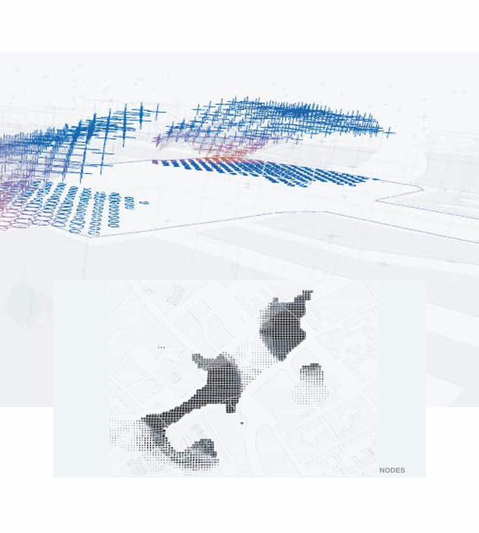
NODES


PHASE 2 _ ARCHITECTURAL PROGRAM

Municipal Library
Bus Stop
Primary Education
Parking
Restaurant
FarmacyVocational Training
Metro L3
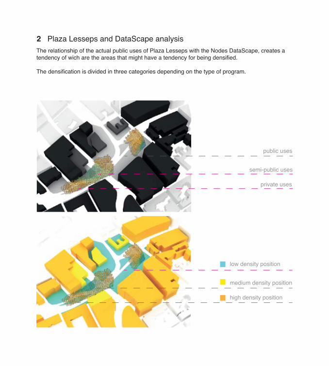
Public uses Semi-Public uses Private uses
Public programs distributed around the Plaza
To buid a relationship between the given architectural program* and Plaza Lesseps programatic context, the Plaza was analyzed in three different program types:- Public- Semi- Public- Private
* architectural program given by the Studio
1 Plaza Lesseps equipments and uses
private uses
semi-public uses
public uses
The relationship of the actual public uses of Plaza Lesseps with the Nodes DataScape, creates a tendency of wich are the areas that might have a tendency for being densified.
The densification is divided in three categories depending on the type of program.
2 Plaza Lesseps and DataScape analysis
high density position
medium density position
low density position

1_ Work Studios
2_ Workshops
3_ Music room
4_ Exhibition area
5_ Meeting rooms
1_ Studio single
2_ Sheltered housing
3_ Two Bedroom
4_ Three Bedroom
5_ Loft
1_ Studio single
2_ Sheltered housing
3_ Two Bedroom
4_ Three Bedroom
5_ Loft
1_ Work Studios
2_ Workshops
3_ Music room
4_ Exhibition area
5_ Meeting rooms
1_ Multipurpose room 1_ Multipurpose room
2_ Bar
3_ Hall
2_ Bar
3_ Hall
4_ Kindergaten 4_ Kindergaten
5_ Auditorium 5_ Auditorium
HOUSING(4,000 m2)
POLIVALENT(2,700 m2)
COMMUNITY(2,600)
SPECIFIC PROGRAMGiven from Studio
PROGRAM RELATIONSHIP (DIRECT & INDIRECT)
LAYER 1(PUBLIC 1,900 m2)
LAYER 2(SEMIPUBLIC 3,900 m2)
LAYER 3(PRIVATE 3,500 m2)
The given architectural program was divided in three layers:- Private- Semi- Public- Public.
3 Architectural program re-organization

SURFACE LAYER 3 (4,300 M2) SURFACE LAYER 2 (4,800 M2) SURFACE LAYER 1(2,900 M2)
(500 m2) Studio single(500 m2) Sheltered housing (1000 m2) Two Bedroom(1000 m2) Three Bedroom(1000 m2) Loft(800 m2) Support Program
(900 m2) Support Program
(1000 m2) Support Program
(1000 m2) Work Studios(1000 m2) Workshops(300 m2) Music room
(300 m2) Exhibition area
(100 m2) Meeting rooms
(1000 m2) Multipurpose room(200 m2) Bar(100 m2) Hall(300 m2) Kindergaten
(1000 m2) Auditorium
SUPPORT
PROGRAM
PUBLIC SERVICE(Bathroom, Mobility..)
CAR ACCESS(Parking lots...)
CAR ACCESS(Parking lots...)
CLOSE SPACES(Cellars, storage room...)
PEDESTRIAN ACCESS(Hall, entries, pedestian path...)
OPEN SPACES(Garden, Free spaces, terraces...)
RECREATION(Coffee, Restaurant, stores...)
SUPPORT
PROGRAM
SUPPORT
PROGRAM
SUPPORT
PROGRAM
CLOSE SPACES(Cellars, storage room...)
PEDESTRIAN ACCESS(Hall, entries, pedestian path...)
OPEN SPACES(Garden, Free spaces, terraces...)
RECREATION(Coffee, Restaurant, stores...)
SUPPORT
PROGRAM
CLOSE SPACES(Cellars, storage room...)
PEDESTRIAN ACCESS(Hall, entries, pedestian path...)
OPEN SPACES(Garden, Free spaces, terraces...)
RECREATION(Coffee, Restaurant, stores...)
PRIVATE USESSEMI-PUBLIC USESPUBLIC USES LOW DENSITY POSITION
MEDIUM DENSITY POSITIONHIGH DENSITY POSITION
In order to relate the programs in terms of functions and with Plaza Lesseps context, they were reorganized through the creation of new and support program relationships .


PHASE 3 _ POPULATION

After the site uses in relation with the Nodes DataScape and the new program relationships and square meteres analysis, in order to intervening the site for further development to achieve volumetric and spatial morphologies, three population rules were created in a generative process with Processing to generate Point Clouds over the Nodes DataScape.
1 Generative process: Population rules
value 10
value 5
value 0
10 mts
40 m
ts
10 mts
bonus= 300 + 100 + 100
bonus= 100 + 100
bonus= 300 + 100Rule 1Population for Private uses.
With this rules, the agents will locate in the highest areas of the DataScape.
value 10
value 5
value 0
10 mts
40 m
ts
10 mts
bonus= 100 + 100
bonus= 300+ 100 + 100
bonus= 300 + 100
value 2
value 7
Rule 2Population for Semi Public uses.
With this rules, the agents will locate in the medium areas of the DataScape.
value 10
value 5
value 0
10 mts
40 m
ts
10 mts
bonus= 100 + 100
bonus= 300 + 100 + 100
bonus= 100Rule 3Population for Private uses.
With this rules, the agents will locate in the lowest areas of the DataScape.

POPULATION 2200 random points over the site300 bonus to points between values 7 and 2 of the Nodes100 bonus to points with a 20 mts distance100 bonus to points with a 10 mts distance from the sourroundings100 bonus to points with a 10 mts distance from the sourroundingsKeep the best 25 Points
Best population for Semi Public uses
Best population for Public uses
POPULATION 3200 random points over the site300 bonus to points below value 5 of the Nodes100 bonus to points with a 20 mts distance100 bonus to points with a 10 mts distance from the sourroundings100 bonus to points with a 10 mts distance from the sourroundingsKeep the best 25 Points
Best population for Private uses
POPULATION 1200 random points over the site300 bonus to points between values 10 (top) and 5 of the Nodes100 bonus to points with a 20 mts distance between them100 bonus to points with a 10 mts distance from the sourroundingsKeep the best 25 Points

,Q�RUGHU�WR�ILQG�WKH�¶EHVW·�SRSXODWLRQ��VHYHUDO�SRSXODWLRQV�KDYH�EHHQ�PDGH�PDLQWDLQLQJ�WKH�PDLQ�parameters but changing their values.
Populations catalog

Final Point Clouds
Private program Semi- Public program
Public program
The resulting population points are exported to Rhino. This process is not linear, is a back foward process between Processing and Rhinoceros, where all the clouds are tested with several ways of connecting the points and evaluate them in square meters in orden to accomplish the program requirements.


PHASE 4 _ DIGITAL TECTONICS

POINTS SELECTION POLYSTRUCTURE
1
2
3
4
1- height_ total points / 4 levels2- boundaries_ exterior points per side3- edges_ vertical organization of exterior point per level4- ground points_ vertical proyection to level 0 of the !rst level points5- structure_ delanunay edges
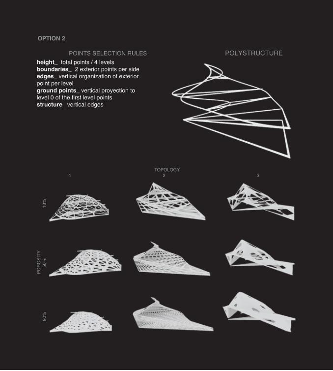
1- height_ total points / 4 levels2- boundaries_ 2 exterior points per side3- edges_ vertical organization of exterior point per level4- ground points_ vertical proyection to level 0 of the first level points5- structure_ vertical edges
1- height_ 4 levels: 0 to 5 / 5 to 10 / 10 to 15 / 25 to 202- boundaries_ 2 exterior closets points per side3- edges_ vertical organization of exterior point per level4- ground points_ vertical proyection to level 0 of the first level points5- structure_ delanay vertical edges
1- height_ 4 levels: 0 to 5 / 5 to 10 / 10 to 15 / 25 to 202- boundaries_ all exterior points3- edges_ closest points between horizontal - vertical boundaries4- ground points_ vertical proyection to level 0 of the first level points5- structure_ vertical edges
After evaluating the previous generated points, 5 rules of how to connect this points were created in order to define Polystructures.Per Polystructure, nine different tectonics were created, each one was evaluated in terms of program requierements and spatial conditions.
1 Generative process: Population rules

TECTONIC

height_ total points / 4 levelsboundaries_ exterior points per sideedges_ vertical organization of exterior point per levelground points_ vertical proyection to level 0 of the first level pointsstructure_ delanunay edges
TOPOLOGY1 2 3
PORO
SITY
90
%
50%
10%
OPTION 1
POINTS SELECTION RULES POLYSTRUCTURE
height_ total points / 4 levelsboundaries_ 2 exterior points per sideedges_ vertical organization of exterior point per levelground points_ vertical proyection to level 0 of the first level pointsstructure_ vertical edges
OPTION 2
POINTS SELECTION RULES POLYSTRUCTURE
TOPOLOGY1 2 3
PORO
SITY
90
%
50%
10%

TOPOLOGY1 2 3
PORO
SITY
90
%
50%
10%
OPTION 3
POINTS SELECTION RULES POLYSTRUCTURE
height_ 4 levels: 0 to 5 / 5 to 10 / 10 to 15 / 25 to 20boundaries_ 2 exterior closets points per sideedges_ vertical organization of exterior point per levelground points_ vertical proyection to level 0 of the first level pointsstructure_ delanay vertical edges

TOPOLOGY1 2 3
PORO
SITY
90
%
50%
10%
OPTION 4
POINTS SELECTION RULES POLYSTRUCTURE
height_ 4 levels: 0 to 5 / 5 to 10 / 10 to 15 / 25 to 20boundaries_ all exterior pointsedges_ closest points between horizontal - vertical boundariesground points_ vertical proyection to level 0 of the first level pointsstructure_ vertical edges


PHASE 5 _ RULES APPLICATION

PLACEMENT
From the previous catalog, the rules 3.3 were selectected. In order to understand the global context of the Plaza in relation with a further morphological development, the rules were applyed to all the PointClouds.As each PointCloud have their own boundaries, the parametric process is adapted in order to work properly.
RULES 3.3height_ 4 levels: 0 to 5 / 5 to 10 / 10 to 15 / 25 to 20boundaries_ 2 exterior closets points per sideedges_ vertical organization of exterior point per levelground points_ vertical proyection to level 0 of the first level pointsstructure_ delanay vertical edges

Selection_one volume to work with

level 1
level 2
level 3
1_ Points Cloud_processing agents_levels organization
2_ Points selection_2 exterior points per level

3_ Polystructure_points triangulation between edges
4_ Surface_delanunay surface between edges points

5_ Structure/ Skin_porosity in the surface without triangulated tension_first level points projected to z= 0 coordinate
6_ Final Volume

Sections
structural stars as connection between nodes diagonal slabs
change to horizontal
geometric slabs difference generates different interior spatial conditions4,5 mts height ~

height_ total points /3 levelsboundaries_ 2 exterior closets points per sideedges_ vertical organization of exterior point per levelground points_ vertical proyection to level 0 of the first level pointsprofile_ from clouds higest point to level perimeterdivision_ of the profile depending on the distance to a unfinished wallprojection_ of the profiles division pointsstructure_ triangulation between prjected and edges division pointsporosity_ mesh between triangulation
Rules modification
After evaluating the previous morphology, the spatial quality, capacity of create interior spaces and the porosity of the volume had to be revised.In order to increase the complexity, some rules should be eliminated, modified and created.

Level 0
Level 1
Level 2
Level 3
1_ Point Cloud_from Processing
2_ Points Selection_closest points to cloud perimeter per level

Higest Point
3_ ProfileBIURP�FORXG·V�KLJHVW�SRLQW�WR�OHYHO�SHULPHWHU��ORZHVWV�SRLQWV�SURMHFWHG�WR���OHYHO�
4_ Division_profiles divided in relation with the proximity to unfinished walls

5_ Points projection_division points projected to 0 level
6_ Triangulation_between projected points with division points

7_ Smooth_mesh triangulation
8_ Morpholohy


PHASE 6 _ LANDSCAPE Rules definitions

2_ Blind walls_center point position
1_ Perimeter_ Plaza definition

3_ Projection_blind walls points to perimeter
4_ Axis projection_ from buildings

5_ Subdivision_ axis
6_ Triangulation_ from blind walls to subdivided points

7_ Paths
8_ Surface_ final Landscape