code of practice · including horizontal directional drilling and thrust boring. some emerging ndt...
TRANSCRIPT

August 2017
Code of Practice Upstream Polyethylene Gathering Networks – CSG Industry
Version 4.0 Supplementary

APGA PE Code of Practice – Version 4 .0 Supplementary Page 2 of 177 pages
Contents
Acknowledgements ........................................................................................................... 3
Preface ................................................................................................................................ 4
1 Scope .................................................................................................................................. 6
2 Network Management System and Safety ....................................................................12
3 Materials and Components .............................................................................................25
4 Design ...............................................................................................................................30
5 Construction .....................................................................................................................54
6 Jointing .............................................................................................................................67
7 Inspection and Testing ....................................................................................................75
8 Pressure Testing ..............................................................................................................80
9 Records Management .................................................................................................. 106
10 Commissioning ............................................................................................................. 109
11 Operations ..................................................................................................................... 118
APPENDIX A – Safety Management Process (Informative) ...................................... 139
APPENDIX B – Pressure Testing (Normative) ............................................................ 151
APPENDIX C – Testing of Final Construction and Repair Tie-ins (Informative) ...... 167
APPENDIX D – Definitions and Standards .................................................................. 169
AMENDMENTS FROM PREVIOUS VERSIONS ............................................................. 174
© The Australian Pipelines and Gas Association 2017
Important note on use of the APGA Code of Practice for Upstream Polyethylene Gathering Networks in the Coal Seam Gas Industry.
This Code of Practice has been developed for the use of organisations involved in the CSG industry, primarily in Australia and New Zealand.
The Code of Practice, and its Companion Papers, and any surrounding material, are copyright to APGA and APGA must be identified as the copyright owner. For licence inquiries, please email [email protected]

APGA PE Code of Practice – Version 4 .0 Supplementary Page 3 of 177 pages
APGA Code of Practice - Upstream PE Gathering Networks CSG Industry
• Acknowledgements
This Code of Practice has been prepared on behalf of the Australian Pipelines and Gas Association (APGA) by members of the Association who are associated with the coal seam gas (CSG) industry. Representative members of all sections of the industry were active participants, including all major CSG producing companies, constructors, manufacturers of polyethylene (PE) resin, pipelines and fittings as well as CSG engineers. APGA gratefully acknowledges the assistance and support of the Plastics Industry Pipe Association of Australia Ltd (PIPA) and its various technical members who provided invaluable assistance during all stages of this Code’s preparation. Many PIPA guidelines are referenced in the Code and all are available on the PIPA website www.PIPA.com.au. In addition, many industry members contributed significant time and resources at the sub-committee working level in developing and reviewing individual sections of this Code and its subsequent revisions. The support of the APGA Board and the APGA Secretariat is also acknowledged.
Disclaimer
Although due care has been undertaken in the research and collation of this Code of Practice, this publication is provided on the understanding that APGA, the authors and editors are not responsible for any errors or omissions or the results of any actions taken on the basis of information in this document. Legislation and regulation relevant to the planning, construction, maintenance and decommissioning of coal seam gas upstream PE gathering networks is subject to frequent amendments by State and Territory governments. To ensure currency and consistency with existing legislation, APGA advises users of this Code to undertake a review prior to commencement of planning each new project. APGA advises users of this Code to seek clarification on approvals processes from personnel with experience in these processes and from the relevant Commonwealth, State, Territory or local government regulatory authorities.

APGA PE Code of Practice – Version 4 .0 Supplementary Page 4 of 177 pages
• Preface
The provision of clean energy is of vital interest to all members of the Australian community. Gas-fired power generation is widely acknowledged as a significant part of the solution to meeting carbon pollution reduction guidelines as the emissions released from modern gas-fired power stations are much less than those from coal-fired power generation.
During the past decade, sufficient coal seam gas (CSG) reserves have been identified and developed to support a CSG to liquefied natural gas (LNG) export industry, by several major resource companies.
Polyethylene (PE) has been used widely throughout Australia for several decades in water reticulation and in the oil and gas industries, especially in metropolitan gas distribution networks. Within the CSG industry, PE has been used as the material of choice for gas flowlines upstream of field compression stations and for CSG water flowline systems. It provides a cost-effective solution with a long service life and is not subject to corrosion.
For the initial decade of CSG field development, common industry practice, based on various water and gas industry standards and codes, was followed for installing the gathering networks throughout the predominantly rural environment of the CSG fields. However, as the industry matured and larger diameter PE pipelines were installed, requirements of the existing standards were seen as less appropriate.
Most importantly, several safety incidents were recorded during PE pressure testing and commissioning, and the industry jointly recognised that further guidance was needed.
This Code has been developed to provide guidance to all industry participants. It is intended to encapsulate the best techniques and methods currently available and is cross-referenced against relevant Australian and international standards wherever possible.
This a supplementary to the fourth version and is intended to capture learnings as a result of the industry’s development. Significant changes in this supplement and version 4.0 include the following:
a) Incorporation of risk-based design in lieu of a fixed ‘risk’ design factor based on the use of physical and procedural measures for risk mitigation in accordance with the location or sub-location class.
b) An increase of the maximum design pressure for gas from 1000 kPag to 1600 kPag as a direct result of the incorporation of risk-based design.
c) Change to the location class to incorporate ‘High Use’ and ‘Sensitive’ sub-location classes.
d) Clarification on the selection and design rating for PE valves and fittings for service in accordance with this Code.
e) Clarification of the scope applicability of ASME B31.3, AS/NZS 4645 and AS4041.
f) Inclusion of the limited application of ‘composites’ in accordance with this Code.
APGA PE Code of Practice – Version 4 .0 Supplementary Page 5 of 177 pages
g) Recognition that future construction will require tie-ins or excavation in the vicinity of live infrastructure (existing pressure flowlines, overhead power lines or buried power cables, and communication cables), necessitating changes to the Construction and Operation sections of the Code to ensure safety.
h) The incorporation of Companion Papers to provide information and best-practice guidelines to the industry, allowing the Code to be limited to mandating essential safety, design, construction and operation philosophies and practices.
i) Inclusion of non-striped ‘black pipe’.
It is an evolving document, and APGA proposes that reviews of the Code occur on a regular basis pending any significant industry learnings or issues.
This Code of Practice has been developed by APGA in consultation with its membership, PIPA, the gas industry and regulatory authorities, particularly those in Australian jurisdictions with a current CSG industry. APGA members in all States are encouraged to adopt this Code and to provide feedback on its application. Other interested parties are also invited to provide feedback on this initiative.

APGA PE Code of Practice – Version 4 .0 Supplementary Page 6 of 177 pages
1 Scope
1.1 Introduction
This Code of Practice has been specifically designed to be, as far as possible, a single reference source, together with the associated informative Companion Papers, for the coal seam gas (CSG) industry in working with polyethylene pipe and fittings. It must be read in conjunction with the Standards referenced in Appendix D, relevant Companion Papers and legislation.
The Code does not specifically detail environmental requirements, it must be read in conjunction with the respective State’s environmental protection legislation, the Operator’s Environmental Licence and the APGA Code of Environmental Practice.
The maximum design pressure for pipelines covered by this Code is 1600 kPa for gas and 2500 kPa for CSG water. The Operator may in accordance with the ‘fit for purpose’ design requirements of this Code design pipelines with higher design pressures. Note that, unless otherwise stated, all references to pressure in this Code refer to gauge pressure.
The Code includes a major change to design factors, using the concept of physical and procedural controls to mitigate risk in lieu of the risk factor. This change has been independently verified in accordance with the fit for purpose requirements of this Code.
The Code addresses safety performance, design, construction and testing of pipeline systems and places particular emphasis on jointing techniques and pressure test methods.
Guidance is provided on the obligations, and process required, to undertake and validate safety management studies (SMS) and the requirement to demonstrate as low as reasonably practicable (ALARP) where risks are considered intolerable and have to be addressed by the implementation of additional risk reduction measures.
Jointing, particularly of large diameter PE pipe, presents challenges and the Code recognises this by proposing mandatory and ongoing training and accreditation of all relevant personnel involved in PE welding including PE welders, quality assurance and quality control (QA/QC) and supervisory personnel.
Pneumatic pressure testing in PE networks is expected to be used for most of the network. It is acknowledged, however, that significant hazards need to be carefully addressed, primarily by exclusion zone design and careful planning. Again, training forms a pivotal role in safety management. Several options for leak testing are listed including tracer gas for CSG nodes or networks.
In Section 5 – Construction, several PE pipe installation methods are provided, including horizontal directional drilling and thrust boring. Some emerging NDT technologies are available; however, the use of NDT is not currently addressed. For more information refer to PIPA technical note TN016 ‘Non-Destructive Examination of PE welds – Emerging Techniques’.
The Code recognises the importance of good engineering design in providing appropriate isolation and segregation within the gathering network. Good engineering design establishes the basis for the proper construction of the pipeline, allowing an extended pipeline life and reducing the risk of future faults or emergencies. The Code also considers technical requirements such as temperature

APGA PE Code of Practice – Version 4 .0 Supplementary Page 7 of 177 pages
re-rating and other design factors, as well as special considerations to be made when pipe systems are in close proximity to populated areas, roads etc.
The Code also sets out the requirements for commissioning and operation of the network systems including the requirement to review and approve important matters related to safety, engineering design, inspection and operation. This version also clarifies requirements related to pipeline suspension and abandonment.
The overall framework of the Code has also changed to include Companion Papers which are intended to provide guidelines for good industry practice.
1.2 Scope
The Code applies to CSG water and gas pipelines and associated piping and components of all diameters which are manufactured to the PE100 specification that transmit CSG, produced formation water (PFW), permeate, saline water and treated water.
Figures 1.2a and 1.2b show the scope of gas and CSG water pipelines covered by this Code. The break between the pipeline and the plant or lease facility shall be defined for each facility. The break should preferably be at, or adjacent to, the first pipeline isolation valve on the side of the valve remote from the pipeline.
Where the pipeline includes carbon or stainless steel components, or components manufactured from other materials, the requirements of Section 4.16 of this Code shall apply (e.g. risers, high point vents, low point drains, isolation valves or manifolds).
The Code also applies to modifications to a pipeline constructed to a previous version of this Code or alternate Standard, as well as alternative PE piping systems, as allowed under Section 4.6 of this code.
1.2.1 Exclusions
The Code does not apply to the following installations:
a) material selection for pipelines constructed of materials other than PE
e.g. polyamide or fibre reinforced plastic
b) potable or drinking water pipelines.

APGA PE Code of Practice – Version 4 .0 Supplementary Page 8 of 177 pages
Low Point Drain
Wellhead Lease
Facility
Manifold,
Isolation Valve or Flow
Switching Facility
Wellhead Lease
Facility
Low Point Drain
Nodal / Hub
CSG Gas Processing
Facility
Nodal / Hub
CSG Compression
and Export Facility
Camp Facilities
Power Generation Facilities
______________________ indicates pipeline / facility included in the scope of this Code if manufactured from PE _ _ _ _ _ _ _ _ _ _ _ _ _ _ _ indicates pipeline / facility excluded from the scope of this Code
Figure 1.2a - Limitations of a Gas Pipeline System

APGA PE Code of Practice – Version 4 .0 Supplementary Page 9 of 177 pages
Amended or Permeate
Water
Wellhead Lease
Facility
High Point Vent
Wellhead Lease
Facility
High Point Vent
Manifold,
Isolation Valve or Flow
Switching Facility
Amended Water
Facility
Buffer Dam
Reverse Osmosis Facility
Storage or
Evaporation Dam
Saline Water Storage Dam or
Reinjection Facility
Reinjection Well Lease
Facility
Irrigation or Third Party
Water Supply
Storage /
Evaporation Dam ______________________ indicates pipeline / facility included in the scope of this Code if manufactured from PE
_ _ _ _ _ _ _ _ _ _ _ _ _ _ _ indicates pipeline / facility excluded from the scope of this Code
Figure 1.2b - Limitations of a CSG Water Pipeline System
PFW
PFW
Saline Water

APGA PE Code of Practice – Version 4 .0 Supplementary Page 10 of 177 pages
1.3 Basis of the Code of Practice The objective of the Code of Practice is to provide requirements for the safe design, construction and operation of a gathering system network that carries CSG and water. The fundamental principles on which the Code of Practice is based are:
a) The Code of Practice exists for the safety of the public and operating personnel and for the protection of the environment.
b) The Operator is responsible for the safety of the gathering system network;
c) All threats to the gathering system network shall be identified and either controlled or the associated risks evaluated and managed to ALARP.
d) The gathering system network shall be designed to have sufficient strength to withstand all design loads to which it may be subjected during construction, testing and operation.
e) The gathering system network shall be designed to be leak tight.
f) The stresses induced during operation of the gathering system network shall remain within the design stress requirements determined in accordance with performance-based material properties resulting from established PE industry test results.
g) Before the gathering system network is placed into operation, it shall be inspected and tested to prove its integrity.
h) The integrity and safe operation of the gathering system network shall be maintained in accordance with the network management system.
i) Where changes occur to parts or the whole of the gathering system network or its surroundings, which alter the original design basis, appropriate steps shall be taken to assess the changes and where necessary implement modifications to maintain the safe operation of the gathering system network.
j) At the end of the networks integrity life, the network shall be abandoned.
k) The design and network management system for the gathering system network shall be documented, reviewed, and approved.
The fundamental principles set out above, including rules and guidelines set out in this Code of Practice, shall be the basis upon which an engineering assessment, including fit for purpose design, is made.
1.4 Retrospective application
The Code of Practice is subject to continuous improvement and, when a revision of part of the Code of Practice is published, the revision should be reviewed by the Operator to identify opportunities for improvement of existing systems.
Publication of a new Code of Practice or revision of the Code of Practice does not, of itself, require modification of the existing physical assets constructed to a previous Standard or a previous edition of this Code of Practice.
Operation of the assets should comply with the requirements of the Network Management System and Safety (Section 2) and Operations (Section 11) of the most recent edition of this Code of Practice.
APGA PE Code of Practice – Version 4 .0 Supplementary Page 11 of 177 pages
Where the changes in the latest edition of the Code of Practice are considered significant, the existing network system shall be assessed against these requirements and where technical or safety non-compliances are deemed to exist, mitigation measures determined by risk assessment shall be applied in accordance with the Code of Practice.
1.5 Companion Papers
Companion Papers are used for guidance on the application of this code and do not form a mandatory requirement. They are used to document technical information and procedures and good industry practice within the upstream PE gathering networks. These documents form part of the suite of documents together with this Code and are intended to be:
a) Used in the design, construction and operation of upstream PE gathering networks.
b) Provide an authoritative source of important principles and practical guidelines for use by responsible and competent persons or organisations.
These documents should be read in conjunction with the requirements of this Code to ensure sound principles and practices are followed.
These documents do not supersede or take precedence over any of the requirements of this Code.
Companion papers are available on the APGA website.
1.6 Approvals
Throughout this Code, items that are considered fundamental to ensuring the safe operation, maintenance and integrity of the pipeline are identified as requiring approval.
Approval shall be given only after the conscious act of reviewing the item, recording the review has taken place and assuming responsibility for the implications of acceptance of the item.
Approval includes obtaining the approval of any relevant regulatory authority where this is legally required.
APGA PE Code of Practice – Version 4 .0 Supplementary Page 12 of 177 pages
2 Network Management System and Safety
2.1 Basis of section
This Section describes the requirements of the management system to be in place before commissioning and operation and to ensure an existing network remains fit for operation.
Networks shall have a documented and approved network management system (NMS).
The NMS shall address the Operator’s approach to the following areas:
a) management
b) planning
c) implementation
d) measurement and evaluation
e) consultation, communication and reporting
f) safety management
g) environmental management
h) construction and commissioning
i) site safety.
The NMS shall include a description of the flowline(s) covered by the NMS including suitable maps (alignment sheets and/or GIS) showing the route of the flowline(s), the location of associated facilities such as compressor and pump stations, low point drains, high point vents and valve stations.
NOTE: In some jurisdictions there are special requirements for safety management systems/plans and these will need to be addressed in the NMS.
2.2 Network management system elements
2.2.1 General
Each element of the NMS is described below and supports each other. The NMS shall comply with those requirements. Much of the responsibility for creating and implementing the NMS lies with the Operator.
In this Code, the term ‘Operator’ refers to the entity that the regulatory authority holds accountable for the network. It should not be confused with the term ‘operator’ (lower case) which refers to a person carrying out a defined task.
How the Operator chooses to structure the NMS is flexible, but it should address the criteria specified in Sections 2.2.2.1 to 2.2.2.6.
2.2.2 Management
The policy on the various aspects of operating the network shall be defined by the Operator. These include, but are not limited to, integrity management, environmental management and occupational health and safety management.
APGA PE Code of Practice – Version 4 .0 Supplementary Page 13 of 177 pages
2.2.2.1 Management structure
A defined management structure for the network shall be established to identify key positions and personnel. An appropriate management structure shall be maintained.
2.2.2.2 Responsibilities, accountabilities and authorities
The responsibilities, accountabilities and authority levels of personnel and or contractors with respect to the various aspects of the operation and maintenance of the network shall be detailed in the NMS.
2.2.2.3 Training and competency
Personnel shall be competent to perform the specific tasks and functions they are responsible for conducting.
The Operator shall establish and maintain procedures for identifying and providing the training needs of all personnel performing functions covered by the NMS.
As a minimum, personnel responsible for the operation and maintenance of the network shall, as applicable to their position:
a) be trained and experienced in all aspects of the equipment in their control;
b) be trained in the obligations of the NMS and briefed in the requirements of the actions identified during the safety management study (see Section 2.7);
c) be aware of properties of the fluid, including its hazards (see AS 4343);
d) ensure the safe disposal of any accidentally discharged fluid; and
e) be capable of arranging for damaged flowlines to be repaired. NOTES:
1. Personnel competency can be assisted though training, development and assessment of personnel by use of relevant competency standards. In the case of:
• Technicians and operators, the relevant units of competency standards are in UEG-11 The Gas Industry Training Package which can be found at www.training.gov.au/Training/Details/UEG11 and the PMA Chemical, Hydrocarbons and Refining Training Package, Units of Competency and Skill Sets which can be found at http://training.gov.au;
• Pipeline Engineers and Approvers, the relevant competency standards are published by the Australian Pipelines and Gas Association and can be found at http://www.apga.org.au/training/competency-area/plastics-pipe.
2. Refer to the appropriate Companion Paper for further information.
2.2.2.4 Resourcing
The Operator shall identify the resourcing, equipment and material requirements for the network’s operation and maintenance, including whether specially trained personnel are required to ensure the appropriate development, implementation and review of the NMS.
APGA PE Code of Practice – Version 4 .0 Supplementary Page 14 of 177 pages
2.2.2.5 Change management
The Operator shall establish procedures for managing changes to the NMS and procedures to ensure they are made in a controlled and authorised manner.
The change management procedures shall also ensure that any changes to the network’s design or operation are managed in a controlled and authorised manner.
Any significant change to the network or its operating context shall be reviewed and approved. Significant change shall be considered to have taken place if the engineering design has been upgraded or modified, or if any event initiates an operational, technical or procedural change in the measures in place to:
a) protect the network and associated installations;
b) promote public awareness of the network;
c) operate and maintain the network safely;
d) respond to emergencies;
e) prevent and minimise product leakage;
f) carry out inspections; or
g) ensure that the plans and procedures continue to comply with the engineering design.
The change management procedures shall address implementation of any resulting NMS changes including notification and training of staff impacted by the change, and responsibilities for any identified actions as well as timelines for completion of those actions.
2.2.2.6 Management review
The Operator shall establish procedures for regular management review of the effectiveness and appropriateness of the NMS.
The NMS shall be monitored, reviewed and, if necessary updated, at least every two (2) years or in the event of any significant change to the network.
2.3 Planning
2.3.1 General
The Operator shall have appropriate planning processes and procedures for the network for any situations that may result from normal and abnormal operations including emergencies. This planning process must include a comprehensive safety management study to ensure that risks to the pipeline and personnel are as low as reasonably practicable. Prior to installation, additional controls can be designed where identified.
2.3.2 Planning for normal operations
When developing the policies and procedures of the NMS, the safety management studies and risk assessments undertaken under this Code of Practice shall be used.
APGA PE Code of Practice – Version 4 .0 Supplementary Page 15 of 177 pages
Control measures required to eliminate risks or reduce them to an acceptable level, including risks to the environment as a result of network operation activities, shall be incorporated into the appropriate procedures.
A process shall also be established for the identification of workplace health, safety and environment (WHS&E) hazards and mitigation of WHS&E risks prior to the commencement of any activity.
2.3.3 Planning and preparation for abnormal operations
Planning and preparation shall be undertaken to ensure readiness for operation of the network in circumstances that are different from those initially considered during the design of the network. These circumstances may include the following:
a) operating under emergency power supplies
b) operating without key assets such as wells or compressors
c) operating at low flow or pressure
d) operating where key areas of the gathering system or access roads are subject to flooding or inundation
e) operating where key areas of the gathering system could be directly exposed to, or in the vicinity of, bushfires.
Contingency plans and procedures shall be developed for actions that may be required in situations of significant disruption to normal operations.
2.3.4 Emergency planning and preparation
Planning and preparation shall be undertaken to ensure readiness for emergency events resulting from the network’s operation and maintenance and also from external events that may affect the safe and reliable operation of the network.
An approved emergency response plan shall be in place and be followed in the event of an emergency.
NOTES:
1. Liaison with relevant emergency services and stakeholders may assist with preparedness for an emergency event.
2. Emergency response exercises are an excellent way of testing preparedness.
2.4 Implementation
The plans and procedures of the NMS shall be implemented covering at least the following:
a) testing;
b) commissioning;
c) operations;
d) network integrity management including:
• external interference management;
APGA PE Code of Practice – Version 4 .0 Supplementary Page 16 of 177 pages
• change of operating conditions and remaining life review;
e) emergency response; and
f) records management.
2.5 Measurement and evaluation
2.5.1 General
The NMS shall incorporate procedures that ensure the following elements are measured and evaluated appropriately.
2.5.2 Data acquisition and analysis
Procedures for identifying, collecting and analysing network operational, maintenance and reliability data shall be established to identify trends in the network’s operation and performance.
NOTE: Analysis of this data should ensure operation of the network continues as planned. It should also identify any negative trend that may result in an event adversely impacting the safe and reliable operation of the network.
2.5.3 Accident/incident investigation and reporting
Procedures for identifying, notifying, recording, investigating and reporting accidents, near misses or incidents resulting from the operation and maintenance of the network shall be established. This shall cover any event that either causes or has the potential to cause:
a) injury or death to network personnel or the public;
b) significant damage to the environment or property;
c) impact on the network’s operation or integrity; and/or
d) uncontrolled gas or CSG water release.
Reporting shall include notification to relevant regulatory authorities including WHS and environmental regulators as required.
2.5.4 System audits
Procedures for planning and implementing audits of the NMS shall be established to determine compliance with and effectiveness of the plans and procedures. System audits should also assess compliance with legal and regulatory requirements and ensure the NMS adequately addresses these issues.
The threats identified and risks evaluated in the safety management study shall be considered in the audits to ensure the following is addressed:
a) the effectiveness of the NMS in managing the risks identified; and
b) the effectiveness of the monitoring procedures in place to identify new or changed risks.
Audits shall be performed by competent personnel who preferably are independent of the section of the NMS being audited. The audit procedures shall cover the timing of audits, including the conduct of external independent

APGA PE Code of Practice – Version 4 .0 Supplementary Page 17 of 177 pages
audits where chosen to be undertaken or where required by regulatory authorities.
Audit procedures shall cover arrangements for verifying the implementation and effectiveness of corrective and preventive actions designed to address any non-conformances identified during the audit.
The outcomes of audits shall be subject to management review. See ISO/AS/NZS 9001 for more information.
NOTE: The results of audit, review and monitoring processes should be used for the purpose of management review of the NMS.
2.5.5 Corrective and preventive actions
Corrective actions are taken to deal with an existing issue while preventive actions address potential issues. Procedures shall be developed and implemented for determining, approving and implementing corrective and preventive actions.
The proposed actions shall be appropriate and commensurate to the risks encountered or identified. The proposed actions shall be recorded and their effectiveness determined by audit.
The basis for any action taken shall be documented and the outcomes of actions taken along with their effectiveness and timeliness shall be subject to management review.
2.6 Consultation, communication and reporting
External people and organisations with a legitimate interest in the safe operation and maintenance of the network shall be identified and appropriately consulted. These will include landowners, local and emergency authorities, regulatory authorities and government agencies.
Procedures shall be established for regular consultation with, as well as communication and reporting to, these identified stakeholders.
These procedures shall include statutory reporting requirements.
2.7 Safety management process
2.7.1 General
The pipeline network safety management process consists of the following:
a) threat identification
b) application of physical, procedural and design measures to identified risks
c) review and control of threats
d) assessment of residual risk.
APGA PE Code of Practice – Version 4 .0 Supplementary Page 18 of 177 pages
2.7.2 Threats
2.7.2.1 General
The underlying principal of threat identification is that a threat exists at a location. A threat is any activity or condition that can adversely affect the network if not adequately controlled.
Threats may exist:
• at a specific location (e.g. excavation risk at a particular road crossing);
• at specific sections of a pipeline (e.g. farming, forestry); or
• over the entire length of the pipeline network.
The same safety management process applies to both location-specific and non-location-specific threats.
2.7.2.2 Threat identification
Threat identification shall be undertaken for the full length of the pipeline network, including stations and pipeline facilities. The threats to be considered shall include, at least:
a) natural events;
b) operations and maintenance activities;
c) construction defects;
d) design defects;
e) material defects;
f) intentional damage; and
g) third-party activities.
The threat identification shall consider all threats with the potential to damage the pipeline network and cause:
• interruption to service;
• release of liquid or gas from the pipeline network;
• harm to pipeline operators, the public, property or the environment. NOTE: Typical data sources used to conduct the risk identification include:
• alignment survey data to determine basic geographical information
• land user surveys in which liaison officers gather information from land users on the specific activities carried out on the land, and obtain any other local knowledge
• third-party spatial information (GIS type data) on earthquakes, drainage, water tables, soil stability, near-surface geology, environmental constraints, etc
• land planning information.
The threat identification process shall generate sufficient information about each threat to allow external interference protection and engineering design to take place.

APGA PE Code of Practice – Version 4 .0 Supplementary Page 19 of 177 pages
For each identified threat, at least the following information shall be recorded:
a) What is the threat and associated risk to the pipeline network?
b) Where does it occur? (the location of the risk)
c) Who (or what) is responsible for the activity?
d) What is done? (e.g. depth of excavation)
e) When is it done? (e.g. frequency of the activity, time of year)
f) What equipment is used, if applicable? (e.g. power of plant, characteristics of the excavator teeth, etc.)
2.7.2.3 Threats to typical designs
The pipeline network design process involves the development and application of typical designs to locations where there is a common range of design conditions and identified threats. Threats common to typical designs shall be documented and controlled.
Each typical design shall be subjected to the safety management process in accordance with this Code to demonstrate that the design provides effective control for the identified threats and their associated risks.
2.7.2.4 Other threats at typical design locations
Prior to construction, each location at which a typical design is applied shall be assessed to determine whether threats other than the threats common to that design exist at that location.
Where other threats are identified, effective controls shall be applied to each of these additional location-specific risks.
2.7.2.5 Non-credible threats
Each threat identified as being non-credible shall be documented. The reason for it being declared non-credible shall also be documented. The validity of this decision shall be considered at each review of the safety management study.
Non-credible threats do not require controls.
2.7.3 Controls
2.7.3.1 General
Effective controls for each credible threat shall be identified and applied using a systematic process.
Physical and procedural controls shall be applied to all credible external interference threats.
Design and/or procedures shall be applied to other threats.
Control is achieved by the application of multiple independent protective measures in accordance with this Code.
Controls are considered effective when failure as a result of that threat has been removed for all practical purposes at that location.
APGA PE Code of Practice – Version 4 .0 Supplementary Page 20 of 177 pages
Where controls are determined to be not effective for a particular threat, that threat shall be subject to potential failure analysis.
2.7.3.2 Control by external interference protection
The pipeline network shall be protected from external interference by a combination of physical and procedural controls at the location of each identified threat. All reasonably practicable controls shall be applied.
The physical and procedural controls applied shall be appropriate to protect the pipeline network from the specified threat. Where physical or procedural controls are not sufficient, other design and/or procedures shall be applied.
NOTE: Re-routing is an example of a design change decision that may be taken if external interference protection is not sufficient.
2.7.3.3 Control by design and/or procedures Control by design and/or procedures shall be achieved in accordance with the following:
a) Design and/or procedures shall be applied to threats other than external interference threats in accordance with this Code.
b) Materials shall be specified, qualified and inspected in accordance with Section 3.
c) Pipeline network design shall be carried out in accordance with Section 4.
d) Erosion protection for the full length of the pipeline network shall be designed in accordance with Section 4.
e) Protection against stress and strain shall be designed in accordance with Section 4 and Section 5.
f) Protection against construction related defects shall be in accordance with Section 5.
g) Operational controls shall be designed in accordance with Section 11.
2.7.4 Residual risk assessment
Assessment of risks shall be undertaken in accordance with AS/NZS ISO 31000.
There are circumstances where risk estimation using quantitative methods may be required to enable comparison of alternative mitigation measures as a basis for demonstration of ALARP, and in some jurisdictions, to satisfy planning criteria.
2.7.5 Safety management validation
Each detailed safety management study shall be validated by a properly constituted workshop, which shall critically review each aspect of the safety management study. Appendix A provides guidance for conducting the safety management study and shall be considered in the validation workshop.
The safety management study shall be completed at design and then reviewed and validated as a result of any of the following changes:
a) at pre-commissioning for operation
b) at any review for changed operating conditions

APGA PE Code of Practice – Version 4 .0 Supplementary Page 21 of 177 pages
c) before recommencement of operation following a flowline failure where such failure has resulted from a mechanism not previously included in preceding studies
d) at any time when new or changed threats including land use occur
e) at any time where there is a change of knowledge affecting the safety of the flowline or network
f) at any review for extension of design life
g) where a part of the network is suspended
h) at abandonment.
A review and validation of the SMS shall be completed at a minimum of five yearly intervals where none of the above changes occur.
Where the issue relates to a specific part of the network, a specific location or specific safety issue, the safety management study may be restricted to only that part of the network for which the issue applies.
Where an extension to an existing network is proposed, for which a safety management study exists, the safety management study for the extension may be restricted to specific new location threats provided the non-specific location threats are reviewed and deemed to adequately cover the threats associated with the network extension.
The safety management study shall:
• be completed at the maximum allowable operating pressure (MAOP) of the network;
• have an evaluation of the threats in accordance with an appropriate radiation intensity contour;
• be subject to a risk assessment; and
• have all risks reduced to ALARP.
In addition, the assessment shall consider the impact of the failure occurring due to a failure of all controls where the maximum pressure exceeds that able to be achieved under the overpressure protection design for the network.
An assessment of the implementation and effectiveness of all threat controls shall be made at each review.
2.8 Environmental management
Risks to the environment from each part of the life cycle of the network shall be identified and control measures implemented so that these risks are reduced to an acceptable level. Preference shall be given to ensuring environmental risks are managed by avoidance (route selection) and, where necessary, specific construction techniques.
The requirements of this Code complement the requirements of regulatory authorities in assessment and management of environmental risk, and are intended to be used during planning, construction and operational phases of a pipeline network to ensure that:
APGA PE Code of Practice – Version 4 .0 Supplementary Page 22 of 177 pages
a) environmental management effort is concentrated on significant risks;
b) environmental management methods are assessed holistically for their contribution to minimising the impact to the environment; and
c) there is a basis for assessing alternative construction and management methods to minimise the impact to the environment.
An analysis of the impacts of construction techniques and design at sensitive locations shall be considered.
Risk of damage to the environment from operational maintenance and abandonment activities shall be identified and control measures developed.
The environmental management plan shall include approved procedures for protecting the environment from construction, operation, maintenance and abandonment activities. The environmental management plan shall also address emergency situations.
NOTE: The APGA Code of Environmental Practice provides industry accepted guidance on management for the environment through the design, construction and operational phases of a project.
The following data shall be obtained prior to conducting the environmental safety assessment:
a) basic environmental data (including cultural heritage and archaeological data)
b) stakeholder survey information
c) constructability and safety constraints
d) emergency response capabilities
e) legislative requirements.
The environment severity classes that apply to the pipeline project shall be defined and approved. Specification of environmental impacts shall, as far as practicable, be expressed in quantified terms.
2.9 Construction and commissioning
2.9.1 Construction safety
Construction of PE pipelines and gathering networks shall be carried out in a safe manner.
The safety of the public, construction personnel, adjacent property, equipment and PE pipelines and gathering networks shall be maintained and not compromised.
A construction safety plan shall be prepared, reviewed by appropriate personnel, and approved. This review shall take the form of a construction safety plan workshop.
Specific construction safety requirements exist in each regulatory jurisdiction. The more stringent of the regulatory requirements and the requirements of this Section shall apply. NOTES:
1. Review by appropriate personnel should include design engineers, construction personnel, workplace health and safety (WHS) personnel, certified environmental practitioners and the approval authority.
APGA PE Code of Practice – Version 4 .0 Supplementary Page 23 of 177 pages
2. The construction safety plan details should be consistent with the nature of the work being undertaken. It may be a component of an integrated construction safety system, a construction safety case (where the regulatory jurisdiction requires this), or a project or activity specific safety plan.
As a minimum, the following shall be addressed:
a) Approved fire protection shall be provided and local bushfire and other fire regulations shall be observed.
b) Where the public could be exposed to danger or where construction operations are such that there is the possibility that the pipeline could be damaged by vehicles or other mobile equipment, suitable physical and/or procedural measures shall be implemented.
c) Where a power line is in close proximity to the route, safe working practices shall be established.
d) Adequate danger and warning signs shall be installed in the vicinity of construction operations, to warn of dangers including those from mobile equipment and the presence of excavation, overhead power lines and overhead telephone lines.
e) Unattended excavations in locations accessible to the public shall be suitably barricaded or fenced off and, where appropriate, traffic hazard warning lamps shall be operated during the hours of darkness.
f) Procedures to be followed for lifting pipes both from the stockpile and into the trench after welding.
g) Procedures for safe use and handling of chemicals and solvents.
h) Frequency and provision of safety talks (tool box meetings).
i) Accident reporting and investigation procedures.
j) Appointment of safety supervisor and specification of duties.
k) Travel associated with attending the worksite.
l) Statutory obligations.
m) Traffic management plan.
NOTE: The APGA document Onshore Pipeline Projects: Construction Health and Safety Guidelines provides guidance on construction safety for the Australian pipeline industry.
2.9.2 Testing safety
The construction safety plan shall address safety through all phases of testing of the pipeline during construction.
2.9.3 Commissioning safety
The commissioning plan shall consider the safety of the activities undertaken through all phases of commissioning and, where required, develop specific procedures to manage the safety during commissioning of the pipeline.
Commissioning safety shall comply with Section 10.

APGA PE Code of Practice – Version 4 .0 Supplementary Page 24 of 177 pages
2.10 Site safety
The safety of the public and maintenance personnel, repair personnel, the integrity of equipment and the pipeline network shall not be compromised.
Control processes shall be established for all personnel to ensure that risks are kept to as low as reasonably practicable (ALARP) and, where necessary, risk mitigation measures are implemented.
A permit to work process shall be required for site works involving high levels of risk, when working with any pipeline or its facilities, to ensure that high levels of WHS&E controls are maintained.
As a key requirement of the system, a job safety analysis (JSA) shall be carried out to ensure that all on site WHS&E hazards are identified and addressed prior to work commencing.
A permit to work should always be issued for:
• work in pipe trenches
• pressure testing
• commissioning
• work on existing operating network including tie-ins
• all other high-risk tasks.
APGA PE Code of Practice – Version 4 .0 Supplementary Page 25 of 177 pages
3 Materials and Components
3.1 General
Polyethylene is a thermoplastic and behaves differently from metals. However, these properties are well-known and are embraced in Australian and other international standards.
PE100 resins used in today’s pipelines have high toughness, excellent resistance to slow crack growth and to rapid crack propagation. They also have an inherent resistance to water and many chemicals. Polyethylene is now the material of choice for many water, waste-water, gas and other pipeline applications.
The following information details the minimum material requirements for PE resins and PE pipe and fitting materials for use in coal seam gas projects.
3.2 Qualification of materials and components
Materials and components shall be fit for purpose for the conditions under which they are to be stored, transported and used, including construction. They shall have the composition, pressure rating (PN number) or standard dimension ratio (SDR), temperature rating and design life specified by the engineering design.
3.3 Compound
PE pipes and fittings used in upstream gathering networks shall be manufactured from PE100 fully pre-compounded material complying with AS/NZS 4131 and listed in PIPA Guideline POP 004 and POP 004A.
NOTE: The test results for compounds listed in POP 004 and POP 004A have been independently scrutinised and are acknowledged to meet the requirements of AS/NZS 4131 and satisfy the temperature re-rating factors listed in this code.
Materials not listed in POP 004 and POP 004A, but for which compliance with AS/NZS 4131 is claimed, may be used provided a full assessment of independent test reports by an appropriately qualified and experienced scientist or engineer confirms compliance.
3.3.1 Pipes
PE pipes shall be manufactured in accordance with AS/NZS 4130 and shall be third party certified by a JAS-ANZ accredited certifier under the StandardsMark, GasMark or WaterMark schemes or equivalent. Marking and product traceability shall be in accordance with the Standard. Appendix A of AS/NZS 4130 shall be used as the basis for demonstrating compliance.
Pipes for gas and CSG water applications shall be Series 1 as per AS/NZS 4130.
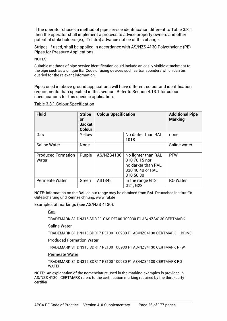
Pipes shall have a method of service identification, and the means of conformance for service identification shall be as per Table 3.3.1.
Alternative methods of service identification shall be documented and approved. As a minimum the pipes shall be marked with the following:
TRADEMARK S1 DN XXX PN XXX SDR XX PE100 100930 F1 AS/NZS4130
CERTMARK – ‘COAL SEAM PRODUCTION GAS/LIQUID PIPELINE’
APGA PE Code of Practice – Version 4 .0 Supplementary Page 26 of 177 pages
If the operator choses a method of pipe service identification different to Table 3.3.1 then the operator shall implement a process to advise property owners and other potential stakeholders (e.g. Telstra) advance notice of this change.
Stripes, if used, shall be applied in accordance with AS/NZS 4130 Polyethylene (PE) Pipes for Pressure Applications.
NOTES:
Suitable methods of pipe service identification could include an easily visible attachment to the pipe such as a unique Bar Code or using devices such as transponders which can be queried for the relevant information.
Pipes used in above ground applications will have different colour and identification requirements than specified in this section. Refer to Section 4.13.1 for colour specifications for this specific application.
Table 3.3.1 Colour Specification
Fluid Stripe or Jacket Colour
Colour Specification Additional Pipe Marking
Gas Yellow No darker than RAL 1018
none
Saline Water None
Saline water
Produced Formation Water
Purple AS/NZS4130
No lighter than RAL 310 70 15 nor no darker than RAL 330 40 40 or RAL 310 50 30
PFW
Permeate Water
Green AS1345 In the range G13, G21, G23
RO Water
NOTE: Information on the RAL colour range may be obtained from RAL Deutsches Institut für Gütesicherung und Kennzeichnung, www.ral.de
Examples of markings (see AS/NZS 4130):
Gas
TRADEMARK S1 DN315 SDR 11 GAS PE100 100930 F1 AS/NZS4130 CERTMARK
Saline Water
TRADEMARK S1 DN315 SDR17 PE100 100930 F1 AS/NZS4130 CERTMARK BRINE
Produced Formation Water
TRADEMARK S1 DN315 SDR17 PE100 100930 F1 AS/NZS4130 CERTMARK PFW
Permeate Water
TRADEMARK S1 DN315 SDR17 PE100 100930 F1 AS/NZS4130 CERTMARK RO WATER
NOTE: An explanation of the nomenclature used in the marking examples is provided in AS/NZS 4130. CERTMARK refers to the certification marking required by the third-party certifier.
APGA PE Code of Practice – Version 4 .0 Supplementary Page 27 of 177 pages
3.3.2 Fittings
3.3.2.1 Marking
Fittings shall be marked in accordance with the requirements of the Standard to which they are manufactured. For all other fittings, the following minimum marking requirements shall apply.
All fittings shall be legibly marked or labelled using lettering of 5 mm minimum height, with the following information:
(a) The manufacturer’s name or registered trademark.
(b) The fitting type in the form of ‘PE-Steel Transition’, as appropriate.
(c) The grade of PE material in the form ‘PE100’, as appropriate.
(d) Nominal size in the form ‘DN315’, as appropriate.
(e) Classification in the form ‘SDR11’, as appropriate.
(f) Traceability data in either of the two following formats –
• A unique batch number; or
• The date of manufacture of the fitting and the identification of place of manufacture.
NOTE: The branding requirements for PE Pipe do not apply to fittings manufactured from the PE pipe.
3.3.2.2 Rating requirements for fittings
Pressure fittings manufactured from polyethylene which are not covered by AS 1463 or AS/NZS 4129 or an equivalent International Standard, and which are intended for use with polyethylene pipes made to AS/NZS 4130 should comply with PIPA Guideline POP 006.
Where fittings are rated to a pressure in accordance with ISO 4437, based on a design coefficient of 2.0, the fittings can be installed and operated in upstream gas gathering systems at a maximum pressure equaling twice the rated gas pressure divided by the design factor for the same SDR calculated in accordance with Section 4.4.
NOTE: The maximum design pressure in accordance with ISO 4437 for SDR 11 pressure fittings manufactured from Polyethylene for gas service is 1000 kPag, because the rating of the fittings in accordance with the ISO 4437 at 20 degrees C is based upon a minimum design coefficient of 2.0.
3.3.2.3 Electrofusion fittings
Electrofusion (EF) fittings shall comply with AS/NZS 4129 and shall be third party certified by a JAS-ANZ accredited certifier under the StandardsMark, GasMark or WaterMark schemes or equivalent. Fittings for above-ground applications shall be black.
3.3.2.4 Fabricated PE fittings
Fabricated fittings shall be manufactured from PE100 pipes complying with Section 0. Butt welding or electrofusion welding shall be the only welding processes used to connect segments or components. Fillet, extrusion or rod welding shall not be used.

APGA PE Code of Practice – Version 4 .0 Supplementary Page 28 of 177 pages
3.3.2.5 Mechanical compression fittings
Mechanical fittings shall comply with AS/NZS 4129.
3.3.2.6 Mechanical couplings
Mechanical couplings shall comply with Section 6.
3.3.3 Previously used pipe
Pipe that has been exhumed after being taken out or removed from service shall not
be re-used in upstream gathering networks.
NOTE: PE100 is a thermoplastic material and can be reprocessed. The pipe manufacturer should be consulted regarding options for collecting reclaimed pipes and off-cuts for recycling into other products.
3.4 Valves
3.4.1 Valve material
Materials used in the manufacture of valves shall be appropriate for the specific fluid being transported and shall be suitable for installation above or below ground as appropriate.
Metallic valves that are subject to corrosion as a result of being installed in a corrosive environment shall be manufactured from a corrosion resistant material such as stainless steel or be provided with a suitable surface corrosion protection such as protective coating, tape wrapping or similar protective system. The grade of stainless steel shall be selected based on the specific fluids properties. Where protective coatings are used, requirements for coating type, surface preparation and thickness shall be determined and specified.
Valve bodies manufactured from PE shall use a PE100 material conforming to the requirements of Section 3.4.2.
NOTE: In many environments stainless steel will also be subject to corrosion. Therefore, buried stainless steel sections or valves should be provided with suitable surface corrosion protection such as protective coatings, tape wrapping or similar protective systems. A decision to not apply protective coatings to buried stainless steel components should be subject to engineering assessment.
3.4.2 Pressure rating of PE valves
The pressure rating of a valve shall be not less than the pressure rating of the piping system within which it operates.
Where valves are rated to a pressure in accordance with ISO 4437-4, based on a design coefficient of 2.0, the valves can be installed and operated in upstream gas gathering systems at a maximum pressure equaling twice the rated gas pressure divided by the design factor for the same SDR calculated in accordance with Section 4.
The PE valves used for CSG water service shall comply with BS EN 12201-4 in its entirety. For gas service, compliance to ISO 4437-4 is required except the allowable operating pressure as detailed in this Section. Alternative standards may be used where approved.

APGA PE Code of Practice – Version 4 .0 Supplementary Page 29 of 177 pages
When the same type of PE valve is used in both gas and CSG water service there may be conflicting requirements between the relevant standards (e.g. ISO 4437-4 and BS EN 12201). The more stringent requirements should be selected.
BS EN 1555-7 provides guidance for assessment of conformity and selection of appropriate testing.
3.5 Transition fittings for PE pipe to carbon steel pipe
3.5.1 Fitting materials
A transition fitting is to be manufactured from PE 100 pipe or carbon steel pipe of the same or higher specification to that of the pipes to which it is being joined.
3.5.2 Pressure rating of transition fittings
All fittings shall have a pressure rating not less than that of the piping system within which they operate and comply with the following test requirements for mechanical compression joint fittings specified in AS/NZS 4129:
• pressure test for assembled joints
• pull-out test.
3.6 Storage and transportation
Storage and transportation shall be in accordance with AS/NZS 2033 and Section 5 of this Code.
Pipe and fittings shall be assessed for transportation damage prior to acceptance.
NOTE: Further information on storage and transportation of PE pipe can be found in PIPA Guideline POP 005 which recommends a maximum of two years exposure to heat and sunlight for other than black PE pipe.
APGA PE Code of Practice – Version 4 .0 Supplementary Page 30 of 177 pages
4 Design
4.1 Basis of section
This section sets out requirements for the design of PE pipelines, gathering networks, and related components such as isolation valves, gathering networks / pipeline connections, manifolds, risers and other connections to above-ground facilities. Materials are limited to pipe and fittings as detailed in Section 3.
Designs for pipelines and gathering networks shall use performance-based material properties resulting from established PE industry test results as provided in this Code of Practice. Installation designs shall use service/design factors from established PE industry experience as provided in this Code of Practice. The design shall use established engineering principles to determine stress, strain and creep resulting from the applied loads and ensure that these remain within acceptable limits for the intended life of the pipeline. The design shall satisfy the criteria for risk mitigation by the use of the risk mitigation controls from industry experience as provided in this Code or as identified in relevant safety management studies.
A structured design process, appropriate to the requirements of the specific gathering network component or pipeline, shall be carried out to ensure that all safety, performance and operational requirements can be met during the design life of the pipelines.
4.2 Design principles
System design uses a mechanism called the ‘Design Basis’ which is detailed below and is pivotal to any design procedure.
This Code of Practice also sets out the methodology for the design of PE100 systems, prescribing a minimum design through the use of design factors and risk mitigation controls as set out in this Section, subject only to the safety management study. There are two mechanisms which can be used either individually or in conjunction to complete a design.
The first and preferred mechanism is ‘Prescribed Design’ and uses a series of formulae and tables derived from theoretical considerations and industry practice.
The second mechanism is called the ‘Fit for Purpose Design’ and relies on a study of a real and present situation and the use of a rigorous risk assessment process to derive one or more of the factors used in the Prescribed Design case.
There is an overarching requirement that the use of the ‘Fit for Purpose’ case is not to be used in any way which would compromise the safety of people, plant or the environment.
The design of the system shall be approved.
4.3 System design
4.3.1 Design basis
The basis for design of the gathering network or pipeline, and for each modification to the gathering network or pipeline, shall be documented in the Design Basis.
APGA PE Code of Practice – Version 4 .0 Supplementary Page 31 of 177 pages
The purpose of the Design Basis is to document both principles and philosophies that will be applied during the development of the detailed design, and specific design criteria that will be applied throughout the design.
The Design Basis shall be approved.
The Design Basis is usually an output of the planning and preliminary design phase of a project.
The Design Basis shall be revised during the development of the project to record changes required as a result of additional knowledge of the project requirements as the detailed design is developed and approved.
The Design Basis shall be revised at the completion of the project to reflect the as-built design.
The design process shall be undertaken in parallel with, and as an integrated part of, the safety management process and shall reflect the obligation to provide protection for people, property, the network, and the environment.
As a primary requisite, every pipeline shall be leak tight and have the capability to safely withstand all reasonably predictable influences to which it may be exposed during the whole of its design life.
The design requirements to be considered shall include, but are not limited to, the following:
a) Safety of the public, property and pipelines is paramount.
b) Design is specific to the nominated fluid(s).
c) Route selection considers existing land use and allows for known future land planning requirements and the environment, and the presence/location of existing pipelines and facilities.
d) The fitness for purpose of the pipeline and associated equipment.
e) Engineering calculations for known load cases and probable conditions.
f) Nominated limits for pressure, temperature and capacity.
g) Pipeline design shall include provision for maintaining the integrity by:
• external interference and external loading protection
• operation and maintenance in accordance with defined plans.
h) Consideration of the types of changes which would prompt a design review.
The design basis also needs to address the following specific issues:
i) The pipe dimensions shall be in accordance with AS/NZS 4130 Series 1. The Standard provides details of pipe diameters, wall thickness and tolerances and matches pipes to a preferred number SDR series. The SDR shall be selected ensuring that it is no less than that required for pressure containment determined from the design pressure fluid, temperature, installation method and location design factors applicable for CSG or PFW and is suitable for any special construction at all locations along the pipeline length.
APGA PE Code of Practice – Version 4 .0 Supplementary Page 32 of 177 pages
j) The pipeline shall be assigned a maximum allowable operating pressure (MAOP) which shall account for elevation changes, the fluid being carried, the design temperature, the installation method and all pipeline fittings and appurtenances. The MAOP shall not be greater than the maximum determined in Section 4.3.5.
k) The design factors are based on a design life of 50 years unless otherwise limited by the material properties and/or temperature design factor table.
l) The risk of the pipeline associated with the location (population density or land use) at all locations along the pipeline length shall be mitigated by the implementation of the selected physical and procedural controls for integrity and external interference applicable to the location under consideration.
m) Extra protection shall be provided where necessary, particularly to prevent damage from unusual conditions such as may arise at road, rail or river crossings, bridges, areas of heavy traffic, from vibration, or the possibility of ground subsidence or other abnormal forces or any other condition that may impact on the integrity of the pipeline.
n) The pipeline shall be pressure tested in accordance with Section 8 to verify that it has the required strength and is leak tight.
o) The battery limits between this Code and design to other standards shall be documented.
4.3.2 Design Basis recording
The Design Basis shall record, as a minimum, the following:
a) A description of the project covered by the Design Basis.
b) Statutory legislation and industry codes and Standards applicable to the pipeline and facilities.
c) Specific physical criteria to be used in the design including at least:
• design capacity of the pipeline, and, where applicable, the pressure and temperature conditions at which this applies – including initial and final capacity where this is significant to the design
• design life of pipeline system as applicable
• design pressure(s), internal and external
• design temperature(s)
• fluids to be carried
• where required, the maximum fluid property excursion and the duration of any excursion beyond which the fluid must be excluded from the pipeline (e.g. temperature or composition).
d) Materials.
e) Minimum design and installation criteria for the pipeline.
f) Specific process and maintenance criteria to be used in the design including, as a minimum, the following:

APGA PE Code of Practice – Version 4 .0 Supplementary Page 33 of 177 pages
• operating and maintenance philosophy
• performance requirements for pipeline depressurisation, re-pressurisation, and isolation valve bypass
• pipeline pressure/flow regime established for the pipeline system
• isolation principles
• limiting conditions.
g) Design principles established as the basis of detailed design.
h) Design philosophies established to guide development of the detailed design.
i) The location of facilities and their functionality.
j) Communications and control principles.
k) Inspection and testing principles.
l) System reliability principles.
4.3.3 System design considerations
The design of an overall gathering system shall take into account factors such as:
• location
• land usage
• existing pipelines and facilities
• future pipelines and facilities
• licensed pipelines and access requirements. NOTE: Refer to the appropriate Companion Paper for further information.
4.3.4 Process design
Process design of the pipeline shall be undertaken in accordance with the system requirements detailed in the Design Basis, and shall include as a minimum:
• process flow diagrams (PFDs) and piping and instrumentation diagrams (P&IDs)
• hydraulic calculations
• transient calculations
• HAZOPs and risk assessments.
The designer may include further activities as deemed necessary for completeness of the pipeline design.
4.3.5 Maximum allowable operating pressure (MAOP) and design pressure for pipelines
The actual maximum allowable operating pressure (MAOP) of a PE pipeline shall be no greater than the lesser of:
a) the design pressure of the pipeline network;

APGA PE Code of Practice – Version 4 .0 Supplementary Page 34 of 177 pages
b) the pneumatic strength test pressure divided by the pressure test factor;
c) for CSG water pipelines hydraulically tested, the lesser of:
• the hydraulic strength test pressure at the low point divided by the pressure test factor; or
• the hydraulic strength test pressure at the high point.
d) for gas pipelines hydraulically tested:
• the hydraulic strength test pressure at the high point divided by the pressure test factor.
The MAOP shall be determined, or calculated, and recorded for each pipeline and/or pressure system.
The pressure test factor is normally 1.25, although may vary depending upon the physical and procedural protection chosen in accordance with Section 4.5, as detailed in Section 8.4.1, Table 8.4.1(a) Pressure Test Factor.
In the case of PFW pipes, the MAOP shall take into account the effect of the static head of the water due to changes in elevation of the pipeline.
4.3.5.1 Design pressure calculation
The pipe Design Pressure shall be calculated from the following equation:
)1(×
×2
SDRC
MRSP
where
MRS = Minimum Required Strength for the material in MPa.
C = Design Factor (See Section 4.3.6)
SDR = Standard Dimension Ratio as per AS/NZS 4130 Series 1
NOTE: The MRS for PE compounds is determined in accordance with AS/NZS 4131 and is expressed as a hoop stress in megapascals. The MRS for PE100 is 10.0 MPa. Pipeline Hoop Stress, σh, is calculated using the following formula:
2
)1(×
)×2(
)(×
SDRP
t
tDPh MPa
where: P = Design pressure in MPa
D = Outside diameter in mm
t = Pipeline wall thickness (minimum) in mm
SDR = Standard dimension ratio
4.3.6 Design factor - general
The minimum design factor for PE gathering pipelines is calculated using the factors nominated below.

APGA PE Code of Practice – Version 4 .0 Supplementary Page 35 of 177 pages
The Design Factor, C, shall be calculated as follows:
C = f0 x f1 x f2 x f3
where:
f0 is the material factor f1 is the operating temperature factor f2 is the installation method factor f3 is the fluid factor
4.4 Prescribed Design
4.4.1 Other design factors
4.4.1.1 Design factor for material (f0)
The design factor for material is included in the calculation of the overall design factor, C. This factor is independent of the fluid and is 1.25 for all fluids.
4.4.1.2 Design factor for temperature (f1)
The design factor for the associated pipe temperatures shall be in accordance with Table 4.4.1.2.
Table 4.4.1.2 Design factor for temperature
Temperature ºC Design factor for temperature f1
Minimum potential service life (years)
≤20 1.0 100 25 1.1 100 30 1.1 100 35 1.2 50 40 1.2 50 45 1.3 35 50 1.4 22 60 1.5 7
At continuous service temperatures above 20C it shall be assumed the service life will not exceed the minimum potential service lives listed in this Code.
NOTE: Definition of minimum potential service life is the expected life when operated at a single temperature. The above values are supported by current test data and should be used in establishing design life.
4.4.1.3 Design factor for installation (f2)
The design factor corresponding with the installation method shall be in accordance with Table 4.4.1.3.
The installation factor shall not be less than 1.0. For installations other than open trench, the factor may be reduced taking into account surface damage and installation loads. Trials may be used to provide guidance to the factor.

APGA PE Code of Practice – Version 4 .0 Supplementary Page 36 of 177 pages
Table 4.4.1.3 Installation factor
NOTES:
1. Pipes may be ploughed in by pulling the pipe into the soil cavity behind the plough. Alternatively, the pipe can be placed into the soil cavity as the plough moves along thereby minimising damage to the pipe.
2. The appropriate value is to be determined by assessing the magnitude of surface damage and longitudinal strain caused by proprietary methods. There are other possible factors to be considered when selecting the installation factor f2 including tensile loads, critical buckling pressures, long term soil loads and the as-built hydraulic grade. Lower values might be appropriate in some circumstances depending upon, for example, the soil conditions, the equipment being used and the length of the drilling operation. For pipes designed and installed in accordance with ‘Polyethylene Pipe for Horizontal Directional Drilling - PPI’ a design factor of 1.0 may be used.
4.4.1.4 Design factor for fluid (f3)
The design factor for the fluid transported shall be 1.0 for gas and CSG water types.
4.5 Risk control and mitigation The design for gas and saline water pipelines shall implement the external interference and integrity controls to mitigate risk in accordance with the applicable class locations for the pipeline. The physical and procedural measures selected in accordance with Section 4.5.1 shall be documented and approved. The selected design shall be reviewed by the safety management study validation workshop.
NOTES:
1. Saline water is defined as water having greater than 40,000 mg/TDS (Total Dissolved Salts as determined by laboratory analysis in accordance with CAS number GIS-210-010).
2. Section 4.5 replaces the prescribed risk factor contained in previous versions of the Code for gas and saline water lines. As the prescribed risk factor for PFW in the previous versions of the Code was 1.0, the application of Section 4.5 to PFW lines is not mandated, however the design of PFW lines shall mitigate the risk associated with the construction and the operation of the line. The principles of this Section may be applied to PFW lines where the SMS has determined that risk mitigation is required due to the nature of the PFW line (e.g. large diameters, higher gas volumes than expected or the closeness of the facility to the public or infrastructure). It is considered that PFW lines in excess of 2000 scm of gas / 100 kl of water should be designed as gas lines.
4.5.1 Risk control requirements
Risk shall be controlled by selecting a combination of physical and procedural controls for both integrity and external interference threats as detailed in Section
Installation Method Installation Factor f2
Open Trench
1.0
Plough-in (Refer Note 1 below)
1.1
Directional Drilling (Refer Note 2 below)
1.2

APGA PE Code of Practice – Version 4 .0 Supplementary Page 37 of 177 pages
4.5.2. The design shall apply the number of control measures as detailed in Table 4.5.1.
Table 4.5.1 Risk control measures
Location classification Integrity External interference
Rural
1 x Procedural
1 x Physical
Rural Residential
2 x Procedural or 1 x Physical and 1 x Procedural
1 x Physical
Rural or Rural Residential High Use / Sensitive
3 x Procedural or 1 x Physical and 1 x Procedural
1 x Physical and 1 x Procedural
The risk control measures required for the Residential (T1) location class shall be determined separately in accordance with Section 4.6. The physical and procedural control measures shall be applied to, or installed over, the pipeline for the full length of the location class. Where a higher location or sub-location class (Rural-Residential, High Use or Sensitive) falls within the lesser location class the requirements of the higher location or sub-location class shall be applied to, or installed over, the pipeline for the full length of the higher location or sub-location class plus a distance either side of the higher location or sub-location class equal to:
a) In the case of gas lines, the distance equal to the 4.7 kW/m2 full diameter rupture radiation contour for the pipeline(s) MAOP and diameter. Where there are multiple gas lines in the location class, the highest 4.7 kW/m2 radiation distance shall be used.
b) In the case of saline water lines, the drainage distance determined by the elevation profile in the vicinity of the Sensitive location class.
4.5.2 Integrity and external interference controls
Integrity and external interference control shall be achieved by selecting a combination of physical and procedural controls from the methods given in Table
4.5.2 to comply with the requirements of Table 4.5.1.

APGA PE Code of Practice – Version 4 .0 Supplementary Page 38 of 177 pages
Table 4.5.2 Integrity and external interference controls
Control Type
Physical controls Procedural controls
Integrity • Enhanced crack resistant pipe.
• Section isolation by instrumented isolation valves (specifically for saline water lines).
• Increase strength test pressure up to MRS rating with increased Test Time.
• Improved QA/QC in accordance with Section 4.5.2.2 b).
• Condition assessment of pipe and joints – IMP inspections.
External Interference
• Depth of cover as per Table 4.10
• Barrier exclusion • Penetration barriers
• Increased frequency of procedural measures listed in Section 11.6.1 (b)
• Implementing additional measures (e.g. construction exclusion zones)
4.5.2.1 Physical controls for integrity risk mitigation Physical controls for Integrity risk mitigation shall be selected from the following:
a) Enhanced crack resistant pipe
The purpose of enhanced crack resistant pipe or fittings is to improve the resistance to stress crack initiation caused by stress concentration. There are several types of stress concentration experienced by operating network pipelines caused by point loads, ligament or mechanical stress.
Use of enhanced crack resistant pipe or fittings, as an effective integrity control, will need to be assessed under Section 4.6 ‘Fit for Purpose Design’.
b) Section isolation by instrumented isolation valves
Section isolation reduces the consequence of the loss of integrity rather than achieving improved integrity. Nonetheless it is considered a physical risk reduction technique. Section isolation can be used for either gas or saline water flowlines.
For section isolation to be an effective control, the isolation valves shall be remotely controlled fail close valves and subject to regular critical function testing as per the integrity management plan (IMP) schedule.
4.5.2.2 Procedural controls for integrity risk mitigation Procedural controls for Integrity risk mitigation shall be selected from the following:
a) Increased strength pressure tests
Increasing either or both the level of pressure and the duration time of the pressure test will provide assurance that components making up the flowline, particularly joints, have a higher level of integrity.

APGA PE Code of Practice – Version 4 .0 Supplementary Page 39 of 177 pages
For increased pressure and duration tests to be effective, the minimum test pressure shall be in accordance with the location class and shall comply with Section 8.4.1 Table 8.4.1(a) for a minimum period of six hours.
b) Improved quality assurance and quality control (QA/QC)
Improved QA/QC can provide improved integrity assurance through material selection and traceability of all materials and joints in the flowline system.
Options should include:
• Inspection of pipe ends to ensure the absence of voids or crystalline structures which would affect the joint quality;
• Monitoring / data logging of weld parameters for butt or EF joints and traceable plotting of the flowline joint quality; and
• Completion of random oxidation induction time (OIT) tests on pipe and fittings.
For increased QA/QC to be effective, the required acceptance criteria needs to increase from Rural through Rural Residential to High Use / Sensitive location classes. The approach to QA/QC shall be documented and approved.
c) Condition assessment
Condition assessment in accordance with the IMP can provide improved integrity and safety assurance by assessment of joint failure or slow crack growth (SCG) as appropriate and remediation of the issue before failure.
Options should include:
• Completion of oxidation induction time (OIT) and Fourier transform infrared spectroscopy (FTIR) tests on targeted lines to confirm the probability of failure.
• Direct external inspection of randomly selected buried joints, excluding butt joints.
• Gas detection surveys and investigation of leakage.
• Corrosion assessment of any metal components in the line. For condition assessment to be effective, the results shall be documented with the associated actions implemented by competent personnel, in an appropriate timeframe, in accordance with the associated risk level. The IMP shall be modified where new or current modes of failure having an increased risk are identified.
4.5.2.3 External interference controls External interference control shall be achieved by selecting one or more physical controls from the methods below to comply with the requirements of Table 4.5.1:

APGA PE Code of Practice – Version 4 .0 Supplementary Page 40 of 177 pages
• depth of cover as per Table 4.10
• barrier exclusion
• penetration barriers.
4.5.2.4 Physical controls for external interference risk mitigation Physical controls for external interference risk mitigation shall be selected from the following:
a) Separation by burial
Burial is a protective method that separates the pipeline from most activities of external parties. Burial may be counted as a physical control when the depth of burial is considered to preclude damage to the pipeline by the defined external interference threats relevant to the location.
For separation by burial to be effective, the depth of cover shall comply with Table 4.10.
b) Separation by barriers
Barriers are a physical protection method against certain types of external interference events, particularly those involving vehicles and mobile plant. Crash barriers on bridges carrying pipelines are an example of separation by barriers.
c) Penetration barriers
Physical barriers may be used to resist penetration. Where a barrier prevents the defined external interference threat from access to the pipeline the barrier may be counted as a physical control.
Barriers may be one of the following:
• Concrete slabs: Where slabs are used to provide protection, they shall have a minimum width of the nominal diameter plus 600 mm. They shall be placed a minimum of 300 mm above the pipeline.
• Other barriers: other physical barriers may also be used.
Barriers shall have the mechanical properties necessary to provide the required protection to the pipeline from the external interference threats, and shall have the chemical and physical properties necessary to maintain the integrity of the barrier.
4.5.2.5 Procedural controls for external interference risk mitigation Procedural controls for external interference risk mitigation are detailed in Section 11.6.1(b). Where a procedural measure for external interference is required in Table 4.5.1, this requirement is additional to the requirements of Section 11.6.1(b), and shall be achieved by:
• increasing the frequency of procedural measures listed in Section 11.6.1(b); or

APGA PE Code of Practice – Version 4 .0 Supplementary Page 41 of 177 pages
• implementing additional measures (e.g. construction exclusion zones). The level of risk reduction achieved in comparison to that achieved under Section 11.6.1(b) shall be verified and documented.
NOTE: Except for major highways (high capacity roads managed by state and territory government agencies) and railways, where due to the installation method the depth of cover is likely to exceed 1200 mm, the High Use locations are most likely to be in the vicinity of the Operator’s compressor stations or camps, so first party interference is the most likely threat. Effective mitigation should be provided through construction exclusion zones, excavation plans and work permitting.
4.6 Fit for purpose design Subject to the exclusions detailed below, the Code of Practice allows the design and construction to occur under a ‘Fit for Purpose’ design as detailed in this Section of the Code of Practice.
4.6.1 Basis for fit for purpose design
This Section sets out the basis for a ‘Fit for Purpose’ design of the pipeline or network, which subject to the conditions below, shall be deemed to comply with this Code of Practice. However, nothing in this process is to place any personnel, community, plant or the environment at increased risk.
Fit for purpose design does not apply to and cannot be used for:
• the use of the option where it has been excluded by legislation;
• the design of plant piping;
• above-ground gas lines;
• the design of above-ground PFW lines; or
• the design for toxic fluids.
Examples of where fit for purpose design could be used, subject to the above exclusions, include:
a) PE materials other than PE100
b) operating conditions - pressures and or temperatures outside the scope of this Code of Practice
c) fluids other than those covered by the Code of Practice (hydrocarbon fluids with C3+, or hypersaline water);
d) Residential (T1) locations as defined in Section 4.8.2.
4.6.2 Minimum requirements
The minimum conditions under which a ‘fit for purpose’ design may be undertaken, and deemed to comply with this Code of Practice are:
a) Where it is inappropriate to use a prescribed design as there are unusual threats, complications or land-use requirements. The areas of unsuitability shall be documented and included in the design.

APGA PE Code of Practice – Version 4 .0 Supplementary Page 42 of 177 pages
b) The fit for purpose design shall be based upon a demonstrated methodology, which complies with international standards, Australian or International experience or research.
c) The design shall be fully documented in a ‘design book approach’ incorporating but not limited to:
• an overview (reason for use)
• basis of design as per (b)
• design calculations
• threat assessments
• risk assessments and mitigations
• construction and test methodology including test factors
• operational and integrity management plans.
d) The design shall be approved.
e) The design shall comply with the requirements of the Network Management System and Safety (Section 2), Records Management (Section 9), Commissioning (Section 10) and Operations (Section 11) of the most recent edition of this Code of Practice.
f) The design shall be constructed and tested in accordance with the most recent edition of this Code of Practice.
g) Where appropriate, the design shall be based upon activity agreements with other entities. For example, an activity agreement may be considered to contribute to the safety or environmental performance of the design (and the network system) where the owners of adjacent assets are party to the agreement and they have systems in place to comply with the provisions of the agreement.
4.6.3 System design – Fit for purpose method
The design factor(s) shall be evaluated subject to the conditions detailed in Section 4.3.5 and 4.4.1. These factor(s) shall not be less than 1.0.
The risk control measure(s) shall be evaluated subject to the conditions detailed in Section 4.5.
The process for evaluating the design factors shall involve a detailed risk and engineering assessment on the proposed operating and design conditions of the gathering system and be subject to a third-party review by a competent designer or assessor. This process shall be approved.
The different design factors or risk control measures require specialist evaluation skills. Relevant personnel shall be competent in the specialist subject matter pertinent to the design factor under consideration as detailed in Table 4.6.3.
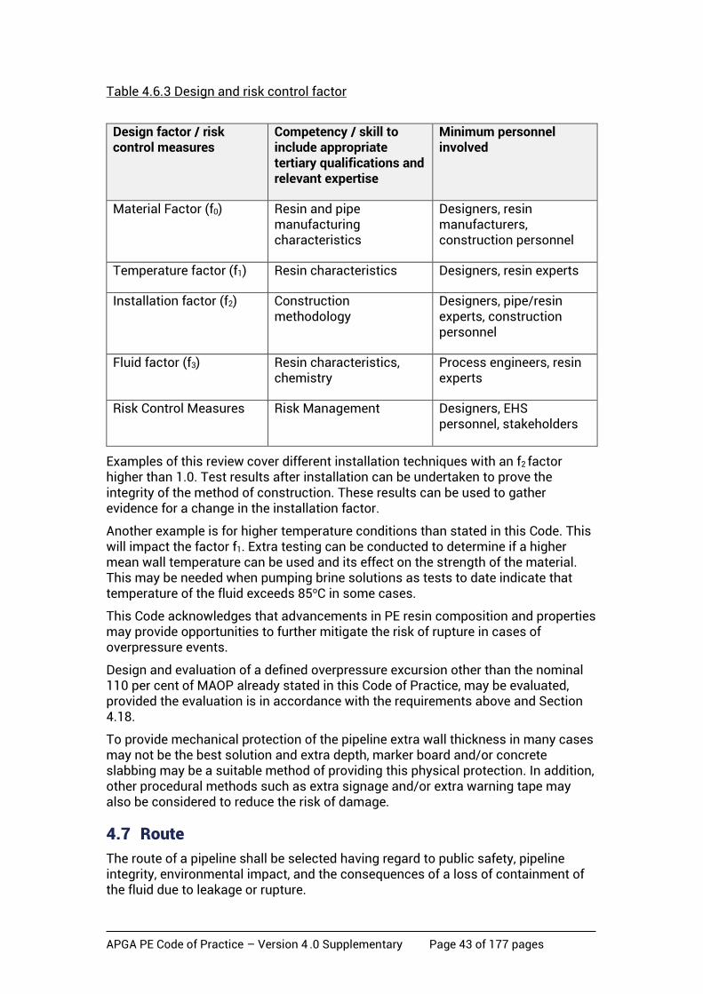
APGA PE Code of Practice – Version 4 .0 Supplementary Page 43 of 177 pages
Table 4.6.3 Design and risk control factor
Design factor / risk control measures
Competency / skill to include appropriate tertiary qualifications and relevant expertise
Minimum personnel involved
Material Factor (f0) Resin and pipe manufacturing characteristics
Designers, resin manufacturers, construction personnel
Temperature factor (f1) Resin characteristics Designers, resin experts
Installation factor (f2) Construction methodology
Designers, pipe/resin experts, construction personnel
Fluid factor (f3) Resin characteristics, chemistry
Process engineers, resin experts
Risk Control Measures Risk Management Designers, EHS personnel, stakeholders
Examples of this review cover different installation techniques with an f2 factor higher than 1.0. Test results after installation can be undertaken to prove the integrity of the method of construction. These results can be used to gather evidence for a change in the installation factor.
Another example is for higher temperature conditions than stated in this Code. This will impact the factor f1. Extra testing can be conducted to determine if a higher mean wall temperature can be used and its effect on the strength of the material. This may be needed when pumping brine solutions as tests to date indicate that temperature of the fluid exceeds 85oC in some cases.
This Code acknowledges that advancements in PE resin composition and properties may provide opportunities to further mitigate the risk of rupture in cases of overpressure events.
Design and evaluation of a defined overpressure excursion other than the nominal 110 per cent of MAOP already stated in this Code of Practice, may be evaluated, provided the evaluation is in accordance with the requirements above and Section 4.18.
To provide mechanical protection of the pipeline extra wall thickness in many cases may not be the best solution and extra depth, marker board and/or concrete slabbing may be a suitable method of providing this physical protection. In addition, other procedural methods such as extra signage and/or extra warning tape may also be considered to reduce the risk of damage.
4.7 Route
The route of a pipeline shall be selected having regard to public safety, pipeline integrity, environmental impact, and the consequences of a loss of containment of the fluid due to leakage or rupture.
APGA PE Code of Practice – Version 4 .0 Supplementary Page 44 of 177 pages
Route selection shall take into account the location of start and end points, well locations and access requirements, hydraulic requirements based on topography, existing services and infrastructure, and current and future land use. Route selection shall form part of the system design process.
The route of a pipeline shall be selected such that the pipeline can be installed, tested, and operated safely and practically. This includes considerations such as limiting of significant elevation changes, proximity to existing roads and infrastructure and avoiding areas of high land use.
Route selection shall also include the grouping of pipelines into common trenches as appropriate, along with consideration of separation distances where new pipelines are required to cross existing assets.
The presence of existing pipelines shall be identified and documented, along with any requirements to amend existing access arrangements in areas where the new pipeline is likely to closely parallel or cross a licensed pipeline.
4.8 Location classification
4.8.1 General
The pipeline route shall be allocated location classes that reflect threats to pipeline integrity and risks to people, property and the environment. The primary location class shall reflect the population density. For a new pipeline, the location class analysis shall be based on the land use permitted in gazetted land planning instruments. Although CSG and PFW pipelines are generally located in remote areas, and within mining and/or petroleum leases under the occupation and control of the various lease owners, consideration needs to be given to the surface use of the land (farming, grazing etc.).
Location class analysis of an existing pipeline shall take full account of current land use and authorised developments along the pipeline route, and consideration needs to be given to land use which is planned, but not yet implemented.
4.8.2 Location classification
The pipeline route shall be classified into Location and Sub-location classes as defined below (adapted from AS 2885.1).
4.8.2.1 Location classes
a) Rural (R1): Land that is unused, undeveloped or is used for rural activities such as grazing, agriculture and horticulture. Rural applies where the population is distributed in isolated dwellings. Rural includes areas of land with public infrastructure serving the rural use; roads, railways, canals, utility easements.
b) Rural Residential (R2): Land that is occupied by single residence blocks typically in the range 1 ha to 5 ha or is defined in a local land planning instrument as rural residential or its equivalent. Land used for other purposes but with similar population density shall be assigned Rural Residential location class. Rural Residential includes areas of land with public infrastructure serving the Rural Residential use; such as roads, railways, canals and utility easements.

APGA PE Code of Practice – Version 4 .0 Supplementary Page 45 of 177 pages
Residential (T1): Land that is developed for community living. Residential applies where multiple dwellings exist in proximity to each other and dwellings are served by common public utilities. Residential includes areas of land with public infrastructure serving the residential use such as roads, railways, recreational areas, camping grounds/caravan parks, suburban parks, and small strip shopping centres. Residential land use may include isolated higher density areas provided they are not more than 10 per cent of the land use. Land used for other purposes but with similar population density shall be assigned Residential location class.
4.8.2.2 Sub-location classes
a) High Use
The High Use sub-location class is defined as areas of activity, within the 4.7 kW/m2 full diameter rupture radiation contour, such as processing plants, site camps, workshops, major highways and railways where personnel or the public is expected to be present on a frequent basis. This sub-location class is applicable to the rural and rural residential location classes for gas and water pipelines having high gas to water ratios (See Note 2 – Section 4.5) only.
b) Sensitive
The Sensitive sub-location class is defined as environmentally sensitive areas such as major waterways and river crossings. This sub-location class is applicable to all location classes for Saline Water pipelines only.
4.9 Isolation requirements
The isolation principles based on risk assessment protocols shall apply to each network system. Each system shall have sufficient valves and isolation facilities as required to enable regular operation and maintenance activities, and limit exposure in the event of a controlled or uncontrolled release. The position, type and spacing of valves and isolation facilities shall be approved.
The location of valves shall be determined for each pipeline. An assessment shall be carried out and the following factors shall be considered:
a) the fluid
b) security of supply required
c) response time to events
d) access to isolation points
e) ability to detect events which might require isolation
f) consequences of fluid release
g) volume between isolation points
h) pressure
i) operating and maintenance procedures.
Valve selection shall provide the appropriate level of isolation and leak tightness based on the fluid in the pipeline and the location. Location may include end-of-line
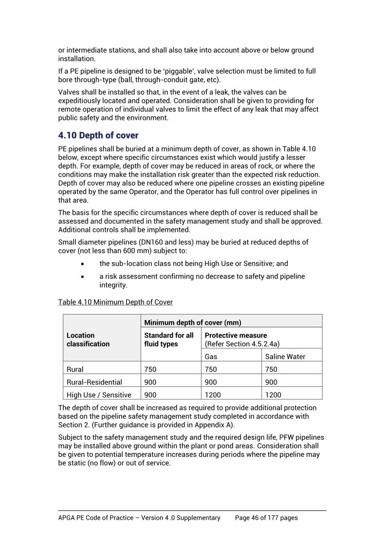
APGA PE Code of Practice – Version 4 .0 Supplementary Page 46 of 177 pages
or intermediate stations, and shall also take into account above or below ground installation.
If a PE pipeline is designed to be ‘piggable’, valve selection must be limited to full bore through-type (ball, through-conduit gate, etc).
Valves shall be installed so that, in the event of a leak, the valves can be expeditiously located and operated. Consideration shall be given to providing for remote operation of individual valves to limit the effect of any leak that may affect public safety and the environment.
4.10 Depth of cover
PE pipelines shall be buried at a minimum depth of cover, as shown in Table 4.10 below, except where specific circumstances exist which would justify a lesser depth. For example, depth of cover may be reduced in areas of rock, or where the conditions may make the installation risk greater than the expected risk reduction. Depth of cover may also be reduced where one pipeline crosses an existing pipeline operated by the same Operator, and the Operator has full control over pipelines in that area.
The basis for the specific circumstances where depth of cover is reduced shall be assessed and documented in the safety management study and shall be approved. Additional controls shall be implemented.
Small diameter pipelines (DN160 and less) may be buried at reduced depths of cover (not less than 600 mm) subject to:
• the sub-location class not being High Use or Sensitive; and
• a risk assessment confirming no decrease to safety and pipeline integrity.
Table 4.10 Minimum Depth of Cover
Location classification
Minimum depth of cover (mm)
Standard for all fluid types
Protective measure (Refer Section 4.5.2.4a)
Gas Saline Water
Rural 750 750 750
Rural-Residential 900 900 900
High Use / Sensitive 900 1200 1200
The depth of cover shall be increased as required to provide additional protection based on the pipeline safety management study completed in accordance with Section 2. (Further guidance is provided in Appendix A).
Subject to the safety management study and the required design life, PFW pipelines may be installed above ground within the plant or pond areas. Consideration shall be given to potential temperature increases during periods where the pipeline may be static (no flow) or out of service.

APGA PE Code of Practice – Version 4 .0 Supplementary Page 47 of 177 pages
4.11 Resistance to mechanical damage
The risk of mechanical damage to the pipeline shall be determined based on location, land use and depth of cover. Where required, the depth of cover shall be increased or suitable protection placed above the pipeline. Land use shall include the frequency and type of deep blade ploughing regularly undertaken on rural properties.
External interference protection shall consider physical measures to prevent personnel access to the pipeline in the vicinity of the CSG well-heads.
As PE pipelines have very little resistance to penetration, additional early warning physical measures such as tracer wire, marker tape or detectable marker products should be used to assist in non-intrusive pipeline detection and early warning confirmation during exploratory dig-ups.
4.12 Separation
Separation of pipelines shall be adequate to address design aspects related to:
• constructability
• future tie-in requirements
• maintenance
• emergency response, especially related to the use of squeeze-off equipment.
4.12.1 Adjacent parallel pipelines
Where pipelines are grouped in a common trench and are servicing various utility providers/owners the minimum separation distances shall be used as shown in Table 4.12.1. Where pipelines within a common trench are operated by an individual operator, deviation from the following separation requirements may be selected based on risk assessment.
Table 4.12.1 Minimum separation distances
External diameter (mm) Minimum Spacing (mm) Preferred Spacing (mm)
≤315 200 300
>315, ≤450 300 400
>450 300 500
Where pipelines of different diameters are used, spacing shall be determined based on the average diameter of the two.
The separation distances may need to be increased should they prove to be insufficient for installation and maintenance purposes.
APGA PE Code of Practice – Version 4 .0 Supplementary Page 48 of 177 pages
4.12.2 Vertical separation of crossing PE pipelines
Pipelines crossing within a gathering system network should be avoided where possible but, where necessary, adequate spacing should be allowed for construction, maintenance and emergency response purposes.
The minimum vertical separation between pipelines shall be 300 mm. This separation shall be filled with compacted embedment material.
Where 300 mm separation is not possible, or is impractical, the separation may be reduced to a minimum of 200 mm based on a risk assessment and with the agreement of the Operator(s) concerned. Compressible packing (e.g. expanded polystyrene) shall be used between the pipes to reduce the risk of point loading.
4.12.3 Foreign crossings
PE pipelines may cross a variety of other services including fibre-optic, telephone and electrical cables, high pressure gas steel pipelines and other gas and CSG water PE gathering lines. Adequate separation shall be maintained, with a minimum of 300 mm, and other precautions, similar to Section 4.12.2 above, may be used.
Where necessary, specific attention should be directed to the provision of additional buried marker tapes and/or marker posts at these locations.
4.13 Special construction
Special construction methods apply to sections of the pipeline that are not generally formed from full pipes joined together and laid in a trench at normal cover.
Because these sections are location and pipeline specific, each application requires special consideration to identify and analyse factors that exist at the location and to develop special designs that are adequate to protect the pipeline from the threats that do, or may, exist at that location.
4.13.1 Above-ground or reduced cover systems – (gas excluded)
PE CSG water pipelines and assemblies may be installed above ground or at reduced cover within a facility or other location where public access is excluded by security fencing or equivalent measures. Designs shall consider issues such as increased temperature and ultraviolet (UV) degradation and include appropriate protective measures. For example, shading may be required for mitigation of the pipe temperature, especially for black pipes.
As UV degradation of coloured PE compounds occurring beyond the normal storage period (i.e. >2 years) may lead to crack initiation within those coloured compounds, all above-ground pipe subject to internal pressures greater than 80 kPag, shall: comply with the following criteria:
• Striped or coloured pipe, other than those defined below, shall not be used, except for temporary lines approved by the Operator – for the particular service.
• Pipe shall be extruded from black compound or black compound with a full coextruded white jacket.
• White jacketing compounds shall comply with PIPA Guideline POP 017 and compounds evaluated against these requirements shall be listed in PIPA Guideline POP004.
APGA PE Code of Practice – Version 4 .0 Supplementary Page 49 of 177 pages
• Pipe fittings shall share an equivalent level of protection as the parent
pipe. This may be achieved by using the same PE material as for the pipe, wrapping, shading, or use of suitable paint.
• MAOP and design pressure shall adhere to Section 4 of this document.
• Pressure testing of above-ground or reduced cover PE pipeline sections shall be performed in accordance with Section 8 of this document.
Above-ground systems shall be installed to provide protection and support for the PE material. Installations shall also include measures for temperature control to ensure the material does not exceed its maximum rated temperature due to environmental effects. This includes special start-up sequences to cool the PE material when surface temperatures result in the pipeline strength being too low to provide suitable pressure containment.
Where PE is installed with reduced cover, the basis for the reduced cover shall be assessed and documented in the safety management study.
NOTE: Above-ground PE installations are not permitted for gas pipework.
4.13.2 Installation of pipes on a curve
PE piping can be safely installed by roping the pipe to accommodate direction changes using methods described in the PIPA Guideline POP 202. Jointing by butt fusion or electrofusion should always be done on straight pipes.
4.14 Design for external loads and seismic survey activity
External loads may be imparted onto the pipeline by various forms of dead and live loads. However, for axle loads <=120 kN no action is needed provided the depth of cover is >0.75 m and the SDR is <=21.
For axle loads >120kN and/or SDR>21, an engineering assessment shall be required. The assessment shall be approved.
External pressure loads may also be imparted onto PE pipelines as a result of seismic surveys or other underground blasting being conducted in the local area. Blast loads are seen as a potential threat to a pipeline, and shall be appraised during the risk assessment.
NOTE: PE pipes have performed better than other materials installed in earthquake zones.
Reference documents such as ‘PRC – Pipeline Response to Blasting – PR-15-712’ and ‘US RI 9523 – Surface Blasting near Pressurised Pipelines’, although not strictly applicable to PE pipelines, may be used as a guide for consideration of seismic loads.
4.15 Pipeline route marking
Pipeline route design and planning shall include the installation of markers to identify the location of PE pipelines.
Both gas and CSG water pipeline marker signs shall comply with Section 5.11.

APGA PE Code of Practice – Version 4 .0 Supplementary Page 50 of 177 pages
4.16 Riser and valve assemblies
Above-ground steel valve assemblies shall comply with the requirements of ASME B31.3 or AS4041 for gas and PFW.
Underground valve assemblies shall be buried in accordance with the manufacturer’s instructions. Provision shall be made for operational and maintenance access to buried valve assemblies.
Location of risers, low point drains and high point vents shall be included on the alignment sheets. The design process shall include provision for capturing and draining liquid from low point drains.
Consideration shall be given to the locking or other valve operating mechanisms to prevent unauthorised operation.
Above-ground steel valve assemblies and risers (including high point vents and low point drains) shall comply with the requirements of ASME B31.3 or AS4041 for Gas.
Vents on PFW lines are to be used in rural locations only, and preferably a minimum of 100m away from the property line of rural-residential and residential areas. Vents on PFW lines shall be designed to vent intermittently.
4.17 Structural design Structural design of pipelines shall take into account all expected stresses and loads which may impact on the pipeline during its lifetime. Transitions from surface to sub-surface should particularly be addressed. Further information can be found in PIPA Guideline TP005 ‘Flexible Pipe Design’.
4.18 Over pressure protection
PE pipelines shall be equipped with facilities to prevent pressures rising above 110 per cent MAOP. The number, type, and location of over-pressure devices shall be documented and approved. Over-pressure design shall ensure the pipeline does not exceed MAOP under normal operating pressure scenarios.
The MAOP of a pipeline can be exceeded by up to 10 per cent for transient situations subject to the pipeline having been tested to 125 per cent of MAOP. However, pressure controllers must not be set to operate continuously at pressures above MAOP.
Operators may nominate an overpressure excursion limit beyond the 110 per cent, for a defined period, given they comply with the requirements of the ‘Fit for Purpose’ assessment detailed in Section 4.6. In such cases the system shall be qualified by pressure testing to the nominated excursion limit times the pressure test factor (fp) in accordance with Table 8.4.1(a) Section 8.4.1.
Pressure control and over pressure protection shall include events during normal and abnormal operating conditions.
Where any pressure control or overpressure protection will discharge fluids from the pipeline, the discharge shall be safe, have minimal environmental impact and not impair the performance of the pressure control or over pressure protection system. Risks associated with liquid discharge shall be managed to ALARP.
4.19 Over-temperature protection
Over-temperature protection is not generally required for CSG PE gathering lines.

APGA PE Code of Practice – Version 4 .0 Supplementary Page 51 of 177 pages
For PFW pipelines, over-temperature monitoring and/or protection shall be incorporated in locations and services where excess temperature is likely to reduce the PE strength to a point where pressure integrity may not be guaranteed (e.g. above-ground pipelines in hot conditions).
The design and selection of over-temperature protection systems shall be documented and approved. Consideration may be given to a system which initially cools the PE material prior to introduction of pressurised fluids.
4.20 Temperature consideration
4.20.1 Temperature re-rating
The pressure rating of PE pressure pipe shall be based on the temperature of the pipe wall, which may be determined from:
a) an assumption of a constant pipe wall temperature typical for continuous service at a set temperature;
b) the determination of a mean service temperature where temperature variations are likely to occur in a predictable pattern; or
c) the maximum service temperature less 10°C for installations where large unpredictable temperature variations occur up to a maximum of 60°C.
For installations where predictable temperature variations occur, the average material temperature shall be determined from (a) or (b) above as follows:
• Across the wall of the pipe, the material temperature taken as being the mean of the outer and inner pipe wall temperatures.
• For pressure and temperature conditions where flow is stopped for prolonged periods so that fluid temperature and outside temperature may equalise, a time weighted mean temperature may be determined.
4.20.2 Provision for expansion and contraction
For fully welded buried PE pipe there is generally no need to allow for thermal expansion and contraction.
For PE100, the value of the thermal expansion coefficient used in calculations shall be 20 x 10-5/°C.
4.21 Static electricity
For CSG PE gathering lines where the gas generally has a high moisture content, static electricity is not generated.
Other areas of the pipeline identified as having potential for static build-up shall be treated as hazardous areas in accordance with AS/NZS 60079.
AS4645.3 Section 5.3 may be used as a guideline for design against the effects of static electricity.
APGA PE Code of Practice – Version 4 .0 Supplementary Page 52 of 177 pages
4.22 Mine subsidence
Where CSG network infrastructure is in the same physical area as underground longwall mining, there is the potential for the PE network to be affected by mine subsidence.
NOTE: Refer to the appropriate Companion Paper for further information.
4.23 Effects of pressure surge – CSG water only
Systems for CSG water shall be capable of withstanding surge or transient loads experienced in the events of pump start-up, shut-down, and unexpected trips or valve closures.
Refer to PIPA Guideline POP 010A for information about the fatigue resistance of PE pipes, which can result from multiple surge events.
Where required, the system design should be supported by transient analyses to identify areas of high surge potential, and determine appropriate restraining mechanisms. Such analyses may be undertaken in conjunction with those for determining over-pressure protection requirements.
Pumps, valves (including opening and closing rates), pipe diameter and flow velocity shall be selected to minimise the possibility of surge events.
Consideration shall also be given to the fitting of such devices as pressure accumulators (pneumatic or hydro-pneumatic) to mitigate water hammer from transient loads and/or air/vacuum valves to mitigate vacuum re-closure water hammer.
4.24 Effects of vacuum – water only
Where potential vacuum effects cannot be avoided, PFW pipelines shall be designed to resist buckling under full vacuum.
PFW pipelines may contain a mixture of water and gas. Design of external protection devices should ensure that air is not introduced into the pipeline in quantities which may give rise to an explosive atmosphere.
4.25 Elevation control – other materials – CSG water only
In water (PFW or saline water) lines, where the pressure at the lowest point exceeds 2,500 kPag, due to elevation head difference, and exceeds the design rating of PE 100 materials under either the ‘Prescribed’ design (Section 4.4) or the ‘Fit For Purpose’ design (Section 4.6), alternate materials for pipe and fittings, such as fibre reinforced plastic (FRP – composites) or glass reinforced epoxy (GRE), may be used for the short distances over which the pressure due to elevation exceeds 2,500 kPag.
These materials have specific design, installation and test methods which differ substantially from that used for PE in this Code. Materials shall be supplied in accordance with API 15S, API 15LR or AS 3571.2. Design, installation and testing shall be in accordance with either ISO 14692 or DNVGL-RP-F119.
Where these materials are used, the requirements of the Network Management System (Section 2), Records Management (Section 9), Commissioning (Section 10) and Operations (Section 11) shall apply where relevant.

APGA PE Code of Practice – Version 4 .0 Supplementary Page 53 of 177 pages
NOTES:
1. ASTM F2805 and F2896 provide additional guidance for the material requirements.
2. AS2885 Appendix AA provides additional guidance for design, installation and test
procedures.
3. Steel is not recommended due to issues associated with corrosion.

APGA PE Code of Practice – Version 4 .0 Supplementary Page 54 of 177 pages
5 Construction
5.1 Basis of section The pipeline network installation and construction shall be in compliance with the engineering design and the following:
a) Construction shall be carried out to ensure the safety of the public, construction and operating personnel, equipment, adjacent property and the network.
b) During construction care shall be taken to minimise damage to the environment.
c) On completion of construction any necessary restoration along the route shall be carried out to minimise long-term degradation of the environment.
d) Construction personnel shall be competent and, where required, qualified for their task.
NOTE: This section covers both PE pipeline construction in new greenfield activities and existing brownfield situations involving live gathering systems.
5.2 Types of construction Several types of construction methodology are used in the installation of PE gathering networks and are covered by this Code. These types are:
• trenching;
• plough-in;
• trenchless; and
• bell-holes.
NOTES: 1. Refer to the appropriate Companion Papers for further information. 2. Specifically. for brownfield locations, the validation of information available for
buried legacy assets, especially electrical cables, should be considered within the work procedures and related excavation and permitting procedures.
5.3 Development of specifications and procedures
5.3.1 Trenching
The following criteria shall form the basis for developing specifications and procedures for installing a PE pipeline in a trench, and covering it:
a) Trench excavation is to be achieved by the use of either a trenching machine or an excavator with a bucket. In both instances, the objective is to achieve a trench bottom free of rocks, stones or other material with an angular profile that may cause damage to the pipe, and a trench profile in continuous contact with the pipe. When such conditions are achieved, the PE pipe may be laid directly on the bed of the trench.

APGA PE Code of Practice – Version 4 .0 Supplementary Page 55 of 177 pages
b) Unless other provisions are made, the installed pipe shall be supported (restrained) in its intended position by the trench and the compacted backfill.
c) Backfilling shall achieve adequate compaction around the pipeline and shall minimise subsequent soil movement.
d) Compaction shall be performed in a manner to ensure that no induced stress is placed upon the pipe.
e) Where backfill material contains rocks or stones that could damage the pipeline, care shall be taken to prevent such damage. Refer to AS/NZS 2566.2 for guidelines.
f) The backfill shall be compacted in a manner that shall not result in future subsidence.
g) Precautions shall be taken to avoid the trench becoming a drainage path (e.g. compaction, backfill material selection, trench-breakers). Refer to AS/NZS 2566.2 for guidelines.
h) The backfilling materials surrounding the pipe shall protect the pipe both during installation and through subsequent operation.
i) The permeability of the backfilled and compacted trench shall be similar to that of the unexcavated material to minimise damage along the trench invert, and potential ‘tunnel’ erosion.
j) The standard of compaction shall be sufficient to deliver the required engineering properties to the backfill.
k) When the trench is required to be bottom padded prior to lowering the pipeline into the trench, the material used shall be screened excavated material or imported fines.
l) Where the trench is flooded with water to consolidate the backfill, steps shall be taken to ensure that the pipeline does not float from its firm bearing on the bottom of the trench.
m) Where necessary, blasting shall be carried out in a safe manner and in accordance with AS 2187.2, statutory requirements, and the blasting procedures shall be approved. In such instances, strung PE pipe should not remain in the blast vicinity.
n) Where scour could occur in a trench, barriers shall be installed to prevent scour. Barriers shall be built of masonry, non-degradable foam, sandbags or other approved material.
5.3.2 Plough-in
Plough-in installation should be achieved by the use of plough-in equipment in combination with excavators or other equipment.
The following criteria shall form the basis for developing specifications and procedures for installing a PE pipeline(s) using plough-in technology:
a) The plough-in installation methodology shall not place induced stress on the pipe which may cause kinking, deformation or damage of the pipeline.

APGA PE Code of Practice – Version 4 .0 Supplementary Page 56 of 177 pages
b) Plough technologies shall be assessed and tested to ensure such conformance.
c) The location of above and below ground existing services shall be identified and located prior to commencing pipe installation with necessary controls implemented.
d) Pipe loading and unloading procedures shall incorporate protection for the work crew from stored energy in the strung pipe.
e) Installation techniques shall ensure that the minimum design depth of cover is achieved.
f) The material surrounding the pipe shall be such that damage from rocks or stones is minimised. Investigation pits within new ground conditions are deemed sufficient to determine the appropriate installation technology.
g) Ground treatment may be necessary, following the installation of pipe, to ensure that the backfill is sufficiently compacted.
h) Care shall be taken to protect the integrity of the pipe during any compaction or subsequent works in proximity to the installed pipe.
i) All members of the work crew shall be competent in all aspects and informed of and understand all above items prior to and during the execution of the works.
5.3.3 Trenchless construction
Trenchless construction comprises various types of subsurface construction techniques that employ materials, methods and equipment to install a pipe or casing between two defined points where it has been determined that the usual open trenching or plough-in is not practicable. Examples include railways, roads and major water courses.
The range of trenchless techniques can be categorised into the following subsets:
• horizontal directional drilling (HDD)
• micro tunnelling (closed face)
• auger or thrust boring (open faced).
In all cases, the profile and layout design shall be performed by qualified engineers with relevant design experience.
The choice of method requires consideration of the crossing configurations, soil characteristics and any possible loads that may be applied to the pipe network infrastructure as a result of sub-terrain conditions or surface activities. Utility authorities may dictate which methods are permitted for the crossing. All trenchless construction methods excavate a horizontal hole (or holes) between the two defined points into which a network infrastructure pipe or similar is inserted. A casing pipe may be initially inserted where necessary. The pipe(s) are pushed or pulled into position depending on the trenchless method being adopted.
Each technique has to ensure that third-party awareness is adequate for the nominated life of the infrastructure; this is achieved by the use of several techniques, as detailed elsewhere in this Code, which include:
• marker signs;
APGA PE Code of Practice – Version 4 .0 Supplementary Page 57 of 177 pages
• marker tape, or equivalent;
• delineated easement (e.g. by clearance, slashing, etc.); and
• tracing and locating materials.
NOTE: Each trenchless construction technique has its own suite of considerations. Refer to the appropriate Companion Paper for further information.
5.3.4 Bell-hole excavation
5.3.4.1 General Bell holes occur in all aspects of both greenfield and brownfield pipeline network construction activities including the following:
• pipeline tie-ins and connections;
• installation of related network facilities low point drains, high point vents, air release vents, test points etc.;
• crossings of existing services, corridors etc.; and
• for trenchless construction, commencement and completion working locations.
Bell-hole excavation shall be performed in a safe manner, using established procedures, work permitting systems and competent staff.
NOTE: Bell-hole excavations involve various hazards (such as hazards associated with the excavation process, working in a confined space, and lifting) which require appropriate controls such as work permitting and endorsed work method statements. Recognised best industry practice should be incorporated into the work procedures prior to commencement.
5.3.4.2 Brownfield
For brownfield bell-holes, additional hazards which are often present include:
• Gas presence, in both the gas gathering line and (partially) in the produced water gathering line.
• Electrical and communication cables in the same existing trench.
When excavation is required, consideration shall be given to:
• Locating of existing services e.g. by pot holing or similar.
• Partial excavation by machine only-normally no closer than 300 mm (the minimum prescribed distance of marker tape above existing PE pipes and related infrastructure).
• Provision of additional care in the vicinity of branch saddles.
• Provision of additional care in the final 300 mm of excavation (for example, excavation by hand).
NOTE: Refer to AS 2566.2 for guidance on the installation of PE and issues associated backfill, compaction and drainage.
APGA PE Code of Practice – Version 4 .0 Supplementary Page 58 of 177 pages
5.4 Survey
5.4.1 General
Gathering networks normally comprise (at least) gas and CSG water lines in the same trench. A survey should be made to locate each pipeline (and all related buried infrastructure) relative to permanent marks and benchmarks complying with Mapping Grid of Australia (MGA 94) or other approved datum. The construction survey shall adopt the same marks and benchmarks as used in the engineering design unless otherwise approved.
The survey shall develop sufficient information on the constructed pipeline network(s) to satisfy the materials traceability requirements of this Code.
Specific survey locations which should be captured are those which occur at crossings (such as road, rail, creeks, rivers, third-party infrastructure), at changes of direction, fence lines and boundaries.
Where a sequence of reference points for location of the network using Global Positioning System (GPS) coordinates exists, it may be used provided it meets the requirements of Section 5.4.2 below.
The existence of services, structures, and other obstructions in or on the route shall be checked, identified and recorded before construction begins, and the location of these shall be recorded in the as-constructed survey record.
5.4.2 Survey accuracy
The survey shall establish the coordinates that suitably locate the pipeline in accordance with the engineering design. The uncertainty of the x-y coordinates shall not exceed 500 mm in R1 location classes and 100 mm in all other classes.
The uncertainty of the as-built top of pipe level shall not exceed 50 mm. Where the survey is required to establish the elevation of the pipe, the accuracy of the elevation measurement shall be documented. NOTES:
1. It is preferred that the recording of the pipeline shall be in x-y-z coordinates to the highest tolerance achievable real time kinematic (RTK) GPS survey equipment using dual frequency receivers.
2. Where survey is by GPS methods, the accuracy of the elevation measurement may be poor unless high quality differential GPS instrumentation is used.
3. Electronic storage options for as-constructed survey data continues to develop; the latest current industry standards should therefore be consulted.
5.4.3 Installation by trenchless construction (survey aspects)
Where a section of the pipeline is installed by trenchless construction methods, an as-built survey shall be undertaken to establish the position of the installation in x-y-z coordinates.
As a minimum:
a) the deviation from the design x-y coordinates shall not exceed 0.4 degrees measured from the coordinates of the pipe string at the start and the end of the drill

APGA PE Code of Practice – Version 4 .0 Supplementary Page 59 of 177 pages
b) the survey shall be compatible with the survey coordinate system used for the pipeline network
c) the accuracy limits of the as-built survey shall be defined on the as-built alignment sheets (and/or GIS).
5.4.4 Records
A record of surveys shall be made so that, after the pipeline network has been constructed, an accurate record of the constructed network can be made to show the precise location of the pipelines and related facilities and should include, as a minimum, weld numbers and pipe numbers for identification.
A consistent weld numbering format, to enable unique numbering and identification of each weld, shall be used and documented.
NOTES: 1. Data should be in digital format, suitable for incorporating in a geographic
information system (GIS).
2. Electronic and paper records of the as-constructed design may also be required.
5.5 Transport, Handling and Storage
5.5.1 General
PE pipes are transported from the extrusion plants to the job-site over a network of bitumen sealed, council-gravelled roads and lightly-gravelled access tracks to the construction right-of-way. Lifting, handling and driving safety protocols need to be considered to minimise the need for stockpiling, especially for large pipe sizes with significant weight (e.g. DN 630 and above).
PE pipes are susceptible to damage from sharp objects and stones as well as damage resulting from dragging or rough handling during loading, transporting and unloading operations.
Pipes may be nested for transport or storage provided that permanent distortion does not occur.
Additional information on storage, transport and handling of PE pipes may be found in PIPA Guideline POP 005. In particular, attention is drawn to the dangers associated with stored energy in coiled pipes or those rolled on drums.
5.5.2 Handling
PE pipes and coils, and other components, shall be handled, transported and stored in a manner that will provide protection from physical damage and other types of deterioration. Specifically for pipe lengths and coils, handling in temporary stockpiles should be minimised by delivering direct to the end-use construction right-of-way location, wherever possible.
For pipe lengths in particular:
a) pipes shall be stacked to prevent excessive localised stresses and to minimise damage;
b) supporting blocks and bearers shall not damage pipes;
APGA PE Code of Practice – Version 4 .0 Supplementary Page 60 of 177 pages
c) pipes that may be subjected to damage from traffic, shall be located either at a safe distance from the traffic or be guarded by protective barriers;
d) temporary pipelines shall be designed, operated and managed to protect the pipe from damage during storage and handling;
e) temporary stockpiles should not be located in areas where environmental damage may occur;
f) stringing, joining and lowering-in operations shall be designed and managed to protect the pipe from damage;
g) during lifting, the pipes shall be adequately protected to prevent damage such as scouring and crushing; and
h) sharp sections bearing against the pipes shall be avoided as these can cause indentations in, or scoring of, the pipe wall.
5.5.3 Storage
In the storage and issuing of pipes, either from an extrusion plant or a temporary stockpile, the principle of ‘first in, first out’ needs to be considered.
A site-specific pipe storage procedure to keep track of what is in the storage yard, to ensure that ‘first in, first out’ occurs, should be prepared for all major pipe storage and marshalling yards.
Pipes shall be stored in a manner to prevent damage from elevated temperatures, contact with chemicals, and prolonged exposure to direct sunlight and distortion. If pipes are to be stored over long periods, the pipes shall be covered to prevent exposure to direct sunlight which can often result in degradation of the PE pipe material. Pipes other than plain black should not be stored for more than 24 months unless protected from direct sunlight. If this is not done, assurance tests and checks may allow the pipe to be used in a de-rated condition.
Pipes stacked for transport or storage shall be adequately supported to avoid distortion. This shall include adequate support and protection using bolsters, timbers or other means to alleviate the potential for damage during transport and storage.
Safety and handling shall be considered with respect to stacking height, taking into account surface and climatic conditions. Bundled packs of pipe should be stacked in a suitable manner to allow the use of mechanical loading and unloading equipment without the risk of accidental damage to the pipes.
Pipes stacked in small quantities at work sites and along the construction right-of-way may be placed directly on flat, smooth ground provided that it is free from hard, sharp objects which could cause damage to the pipe.
5.5.4 Coils and drums
PE pipe may be stored and transported in coils or wound on drums. In both instances, stored energy is involved. Care shall be taken when uncoiling or unrolling the pipe to address this potential hazard and the movement of the ends of the pipe should be controlled to prevent whiplash.
Additional information on storage, transport and handling of PE pipes may be found in PIPA Guideline POP 005.
APGA PE Code of Practice – Version 4 .0 Supplementary Page 61 of 177 pages
5.5.4.1 Coils
When PE pipe is transported in coils, care shall be taken during uncoiling to ensure safety of personnel, from risk associated with stored energy contained within the coils, as well as ensuring sharp objects do not score the pipe. When stored for use on a work vehicle, pipes should be uncoiled on a dispensing reel.
Coiled pipe shall be stored on a flat surface and only to such a height that ensures the bottom layer does not become distorted.
5.5.4.2 Drums
PE Pipes stored on drums are still susceptible to risks associated with stored energy although the pipe is better restrained on a drum.
Drums are very heavy and should always be handled with the appropriate equipment.
Drums must be stored on flat, stable ground to ensure that they will not topple over, and should be controlled by the use of chocks to ensure that they do not roll out of position.
When lifting a drum from a vehicle, it should be lifted by the use of a strap placed under the plate carrying the pipe, and not through the outer rim of the drum, as this will bend the rim inwards and damage both the drum and the PE pipe.
If lifted by a fork, the tines should be fitted inside the drum under the cross members, making sure that the length of the tine is sufficient to fit through the drum to support both sides.
Under no circumstances should a drum be allowed to drop from the back of a vehicle onto the ground, or even onto a stack of tyres or other buffer system.
When lifting steel drums, care shall be taken to ensure the drums do not come into contact with overhead wires.
5.6 Clearing and Grading
Clearing and grading shall be carried out in accordance with the EMP and other related approvals.
The route shall be cleared to the width necessary for the safe and orderly construction of the pipeline. The cleared width shall not exceed the permissible width of the right of way.
Where a route is graded, permanent damage to the land shall be minimised and soil erosion prevented.
In developed farmland, liaison with property owners is to be maintained to minimise disruption to farming activities.
NOTE: Consideration should be given to locating the right of way alongside existing or new access roads and tracks to minimise overall impact.
5.7 Stringing of PE Pipes
PE pipe should only be strung on areas of the right of way where clearing and grading is complete.
When pipe is strung from end to end, adequate provision shall be given to allow for access by property owners, fauna and construction traffic.

APGA PE Code of Practice – Version 4 .0 Supplementary Page 62 of 177 pages
5.8 Welding of PE Pipes
A unique weld numbering system shall be established so as to identify each production weld and tie-in for traceability records.
Each pipe shall be internally and externally inspected to ensure compliance with wall thickness and end preparation requirements.
Additionally, each pipe shall be internally inspected for any obstructions that might prevent the effective operation of the pipeline. These, together with any grit or dirt that might interfere with the jointing process, shall be removed prior to welding.
The welding process of PE pipe shall be nominated and approved prior to welding procedures being developed and prior to commencement of any PE welding.
5.9 Laying of the Pipeline
5.9.1 Stresses induced during laying
Laying stresses, induced in the PE pipeline during construction, shall be minimised. The trench bottom shall be constructed to provide a uniform padding for the pipeline and shall be free from stones or hard, sharp material that could damage the pipeline.
Where long sections of pipeline that have been jointed alongside a trench are lowered into the trench, care shall be taken not to jerk the pipeline or impose any stresses that could kink or cause a permanent bend in the pipeline. Slack loops or snaking can sometimes be used to reduce induced stresses.
5.9.2 Thermal expansion and flexibility
The high thermal linear expansion factors of plastics need to be taken into consideration when laying PE pipelines on extremely hot or cold days. To limit the effects of expansion and contraction, pipelines should be protected from direct sunlight wherever possible, and final connections of the pipeline to existing systems shall be performed only after the pipeline temperature has stabilised.
NOTE: The coefficient of thermal linear expansion for PE pipe is considerably higher than that of steel (approximately 10 times higher).
5.9.3 Covering ends
Ends of the pipeline shall not be left open.
5.10 Positioning
5.10.1 Alignment
Pipelines should be laid as true to line. Any significant deviation shall be recorded.
5.10.2 Structures
Pipelines shall not be installed under structures and foundations where:
a) the integrity of the pipeline will be affected;
b) the integrity of the structure or foundation will be affected; or
c) a gas leak may accumulate in a confined space.
APGA PE Code of Practice – Version 4 .0 Supplementary Page 63 of 177 pages
5.10.3 Installation of above-ground pipes
Any installation of above-ground pipework for PE pipe must be to the requirements set by the Operator. Above-ground carbon steel pipework shall comply with the relevant standard.
NOTE: Above-ground PE installations are not permitted for gas pipework.
5.11 Pipeline locating methods
5.11.1 Tracer wire, detectable marker tape and detectable marker products
5.11.1.1 General
When installing a pipeline in an open trench, one of the following shall be installed above the pipeline:
• tracer wire and marker tape or;
• detectable marker tape or;
• detectable marker product.
This is to enable the location of the pipeline to be traced with a pipe locator, and so reduce the likelihood of damage during future excavations in the vicinity of the main or service.
The products shall also be impervious to corrosion by being totally encased in corrosion proof materials.
When installing a pipeline using a boring technique, consideration should be given to the use of tracer wire, or an appropriate detectable marker product, which can be drawn in with the bore, where such installation is considered to be beneficial.
5.11.1.2 Tracer wire
Where installed, tracer wire should be durable and connected using an approved technique.
Tracer wire shall be metallic, electrically insulated and have a minimum diameter of 14 gauge. Tracer wire shall be resistant to corrosion damage either by use of coated copper wire or by other means.
Tracer wires shall not be electrically connected to a source of electrical current for which they are not designed. This includes steel pipelines and any earthing or grounding systems and risers.
5.11.1.3 Detectable marker products
Detectable marker products shall use passive marker technology which are embedded into an industry colour coded caution tape or carrier. When used as a pipeline locating method, the detectable marker product shall enable continuous tracing of the pipeline.
5.11.2 Pipeline marker signs
This Code mandates the placement of markers for each buried pipeline at a wide range of specific locations. Pipeline marker signs shall comply with the requirements for safety signs in accordance with AS 1319 ‘Safety Signs for the Occupational Environment.’

APGA PE Code of Practice – Version 4 .0 Supplementary Page 64 of 177 pages
The purpose of pipeline markers is to alert people who are planning to work near a pipeline but have not contacted the operator to the presence of the pipeline and to the possible consequences of inflicting unintended damage.
The requirement for effective pipeline marking applies regardless of land use, including remote areas.
5.11.3 Sign location
Signs shall be placed at the following locations and be inter-visible:
a) Both sides of public roads.
b) Both sides of railways.
c) At each property boundary (and at internal fence lines as appropriate).
d) Both sides of creeks and rivers.
e) Both sides of vehicle tracks.
f) Each change of direction.
g) Utility crossings (buried or above ground).
h) At all pipeline facilities.
i) At all other places where signs marking the location of the pipeline are considered to contribute to pipeline safety by properly identifying its location.
Signs must not exceed the maximum separation listed below for classification areas:
• R1 - 500 metres
• R2 - 250 metres
• T1 - 100 metres
• High Use or Sensitive sub-locations - 100 metres.
Note: In land subject to cultivation where the required sign placement, as specified above, is unacceptable to the landowner or cannot be maintained, an acceptable alternative is to place an appropriate sign at fence lines and at every gate giving access to the cultivated area. Elsewhere on the property, signs need to be placed on the RoW as close as practical to the edges of cultivates areas.
5.11.4 Marker sign contents
Marker signs shall:
a) indicate the approximate position of the pipeline;
b) indicate that excavating near the pipeline is hazardous; and
c) include a direction to contact the pipeline operator before commencing excavation near the pipeline.

APGA PE Code of Practice – Version 4 .0 Supplementary Page 65 of 177 pages
5.11.5 Buried pipelines installed in parallel
Buried PE pipelines running in parallel are at particular risk of being impacted when an excavation or drilling machine operator is unaware of the presence of more than one pipeline in the immediate vicinity. Therefore, where pipelines share a common trench, or where two or more pipelines run in parallel, one of the following options shall be applied:
a) Individual pipeline marking
Where pipelines are marked individually, the requirements stated above shall apply as a minimum requirement for each pipeline. At each location, where the presence of one pipeline is indicated by a marker sign, an additional sign shall also be placed to represent the presence of each additional pipeline in the vicinity. Posts shall be separated from each other to clearly indicate the presence of all pipelines.
b) Grouped pipeline marking
Alternatively, pipelines may be marked by a single sign at each location. In such cases, the sign shall clearly indicate the presence of multiple buried pipelines or services in the vicinity. The marker sign format, visibility and display of company information shall be in accordance with the above requirements.
5.11.6 Marker tape
When marker tape is used as a pipeline locating method, it shall be installed at all locations designated by the design or alignment sheets. Where two pipelines are laid in a common trench, such as gas and CSG water, a marker tape that indicates the presence of each of the pipelines is to be installed separately, unless an alternative arrangement is developed and approved.
5.12 Reinstatement
After backfilling has been completed, construction tools, equipment, and debris shall be removed. Areas that have been disturbed by the installation shall be reinstated. Reinstatement should be completed as soon as practicable.
Appropriate measures shall be taken to prevent erosion and minimise long-term degradation of the environment (e.g. the construction of contour banks or diversion banks).
Fences that have been removed to provide temporary access to the route shall be re-erected.
Reserves shall be reinstated in accordance with the prescribed requirements of the appropriate authority.
In developed farmland, it shall be ensured that topsoil is being replaced without contamination, and drains and general contours are reformed.
5.13 Records
At completion of construction of each section of the pipeline gathering network, survey data and as-built data that identify and locate each and every component of the network shall be prepared in accordance with operational requirements.

APGA PE Code of Practice – Version 4 .0 Supplementary Page 66 of 177 pages
All spatial data shall be referenced against an approved datum (e.g. MGA94, GDA55, AHD etc.) and provided to the operator in an approved electronic format.
Where necessary, permanent reference marks and benchmarks shall be provided.
NOTES:
1. As detailed in Sections 5.4, awareness of the exact location of all related network buried services, which can include HV electrical cable, are considered a key control in the prevention of inadvertent damage by third parties; or during brownfield activities by the operator.
2. Refer to the appropriate Companion Paper for further information.
The scale and detail shall be appropriate to the location class and complexity of that location. In addition to survey data and drawings the following design and construction records shall be prepared:
a) Design and approval records: The design and approval records are the following:
• design basis
• design drawings revised to as-built status
• relevant project specifications and data sheets
• location class
• records of land ownership
• operating procedures that form part of the design
• safety and environment related records
• approvals and relevant correspondence with regulatory authorities
• materials and components used in the pipeline network, together with names and process of manufacturer of key components.
b) Manufacturing and construction records: The manufacturing and construction records required are the following:
• Manufacturing data records including the traceability of all materials and components, and all associated test results and inspection records.
• Welding records.
• Hydraulic and/or pneumatic pressure testing records (including both strength and leak testing).
• All other tests and inspections that are required to verify the integrity of the pipeline network in accordance with this Code of Practice.
• Any construction information that may be relevant to maintenance of the pipeline network.
c) Commissioning records: Commissioning records are to include all records from commissioning activity relevant to the ongoing operation and maintenance of the PE pipeline network.

APGA PE Code of Practice – Version 4 .0 Supplementary Page 67 of 177 pages
6 Jointing
6.1 Basis of section
This section includes general information on the recommended procedures for the most common methods of joining PE pipe and fittings.
The user of this jointing information must consult and follow appropriate safety instructions for jointing equipment, which are available from manufacturers. Further information is contained in PIPA Guidelines POP 001 and POP 003.
6.2 General provisions
PE pipe or fittings can be joined to each other only by heat fusion (welding) or with mechanical fittings.
NOTE: PE pipe and fittings for CSG and PFW applications cannot be joined by adhesives, cements or elastomeric joints.
PE pipe and fittings may be joined to other materials by means of mechanical fittings, flanges, or other qualified types of manufactured transition fittings. There are many types and styles of fittings available from which the user may choose, but whatever fitting is used it must comply with the requirements of Section 3 of this Code.
Each jointing method offers its particular advantages and limitations for each situation the user may encounter. Contact with the relevant manufacturers is advisable for guidance in proper applications and styles available for joining.
6.3 Heat fusion
6.3.1 Introduction
There are three types of heat fusion joints currently used in the industry - butt fusion welding, electrofusion welding and saddle fusion welding. The principle of heat fusion is to heat two surfaces to a designated temperature, and then hold them together by application of a sufficient force. This force can be applied either by a direct force holding the ends of the pipe together as in butt fusion welding and saddle fusion welding or by indirect forces caused by the melting of two surfaces in a confined space as in electrofusion welding. In all three cases, this causes the melted materials to flow and mix, thereby resulting in welding or fusion. As soon as the joint cools to near ambient temperature, it is ready for handling.
The following sections provide general procedural guidelines for each of each of these heat fusion methods.
NOTE: Fusion heating of new pipe to previously in-service pipe may require additional steps to ensure satisfactory weld quality where liquid hydrocarbons or moisture may have been absorbed from process fluids. Refer to the appropriate Companion Paper for further information.

APGA PE Code of Practice – Version 4 .0 Supplementary Page 68 of 177 pages
6.3.2 Butt fusion welding
The most widely used method for joining individual lengths of larger diameter PE pipe is by heat fusion of the pipe butt ends as illustrated in Figure 6.3.2a.
Figure 6.3.2a – Standard Butt Fusion Joint
This technique, which precludes the need for specially modified pipe ends or couplings, produces a permanent, economical and flow-efficient connection.
Butt fusion welding can be carried out only with pipe or fittings of the same SDR unless a suitable transition piece, approved by the manufacturer, is used or the pipe end is transitioned as shown in Fig 6.3.2.
A transition piece can be used only for joining one SDR to the next SDR, that is not more than one SDR step up or down per transition (See Figure 6.3.2b). The transition piece needs to be manufactured in a controlled environment with approved machining processes and equipment. Other transition pieces or transition pipe/fitting ends are to be to an approved design and manufactured and certified in a controlled environment. All components must have adequate nominal pressure rating for the operating conditions.
A = Nominal wall thickness of the thinner pipe
B = Nominal wall thickness of the thicker pipe
C = 0.15A
Dmin = the lesser of 50 mm and 2A
Figure 6.3.2b - Transition piece design for one SDR step
Field-site butt fusions may be made by trained operators using specially developed butt fusion machines that secure and precisely align the pipe ends for the fusion process.
Dmin

APGA PE Code of Practice – Version 4 .0 Supplementary Page 69 of 177 pages
6.3.3 Types of butt fusion welding
6.3.3.1 Background information
A successful butt weld requires the correct combination and sequence of the welding parameters of time, temperature and pressure.
Various proven butt fusion methods with minor differences have been in use in different countries for many years. ISO 21307 contains three distinct fusion methods described below for pipe and fittings with a wall thickness up to and including 70 mm.
It is essential that the parameters specified for a given method are followed. Do not mix and match parameters for each method.
NOTE: Wall thickness is expected to very rarely exceed 70 mm in CSG development. However, where wall thickness exceeds 70 mm, welding parameters should be agreed between the operator and the installer. Under these circumstances the pipe and fitting supplier should also be consulted.
The three methods employed are as follows –
a) Single pressure-high fusion jointing pressure.
This method has been used extensively in North America and has been almost universally adopted within the CSG industry. The weld interface pressure is approximately three times the low-pressure method detailed below and, as a consequence, more of the molten material is extruded from the weld zone, thereby enabling a reduced cooling time. Extra attention is required to ensure that suitable welding machines are used to ensure that the high-pressure parameters are achieved in a safe manner, with confirmation to be sought from the machinery manufacturer. In addition, the welding operator shall be competent and sufficiently trained, experienced and proficient with the parameters.
NOTE: Several equipment manufacturers have adapted this technology to be used in tracked equipment which provides mechanically-assisted lifting equipment to assist in the alignment of the PE pipe, and a controlled environment for the welding process. In addition, controlled conditioned air cooling is available to reduce the total welding duration for a butt fusion weld. ASTM F2620-11 Section 8.3.7 Note 8 states:
“Pouring water or applying wet cloths to the joint to reduce cooling time is not acceptable. Applying chilled air is acceptable only as part of a controlled cooling cycle procedure where testing demonstrates that acceptable joints are produced using the controlled cooling cycle procedure.”
No change to the welding parameters set by the manufacturer of the butt fusion welding machine is involved.
b) Single pressure-low fusion jointing pressure This method has been used in most European countries and has been widely used by utilities in Australia. The single pressure-low parameters specified are very similar to those previously specified by PIPA.
APGA PE Code of Practice – Version 4 .0 Supplementary Page 70 of 177 pages
c) Dual pressure-low fusion jointing pressure This method is used by the water industry in the U.K. and in Europe. These parameters are not commonly used in Australia.
Welding parameters are detailed in PIPA Guideline POP 003 which provides guidelines for butt fusion welding parameters as detailed above. Data loggers are now extensively employed to verify conformance to the nominated welding parameters.
6.3.3.2 Environmental conditions for carrying out butt fusion welding
The fusion or welding process is sensitive to weather and climatic conditions and, as such, the butt welding process needs to be carried out in clean, dry and draft free conditions. To manage these aspects the following is advised:
a) Where necessary, use a weather shelter or cover to keep moisture and dust away from the prepared pipe ends.
b) When temperatures fall near or below zero, special precautions may need to be taken – consult pipe manufacturer’s recommendations.
c) Cover the remote open ends of the pipes being welded to avoid draughts. Air can be drawn through open ends and pass over the surfaces being welded, cooling them prematurely, which can result in a cold weld.
6.3.3.3 Planning for successful butt fusion welding
To ensure the integrity of the butt welds the following procedures should be adopted:
a) Select a qualified welding contractor. A qualified butt welding contractor shall have:
• demonstrated experience in butt welding of PE pipe
• suitably sized equipment which has been maintained in good condition with calibration status documentation available for temperature and pressure measurement
• qualified operators who have an up to date log detailing project and welding experience.
b) Assess the proposed welding procedures.
• Pre-qualified welding procedures for pipe class and diameters being proposed for the project and the welding machines which will be used and destructive weld testing data may be considered.
• Carry out trial welds on the actual pipe to be used for the contract and have these destructively tested to meet the specified performance requirements (testing and minimum performance requirements are detailed in Section 7 – Inspection and Testing).

APGA PE Code of Practice – Version 4 .0 Supplementary Page 71 of 177 pages
• Determine and document the agreed welding parameters, procedures, and welding equipment (this may also include the use of welding tents, pipe end covers etc.).
• The agreed welding parameters, procedures and welding equipment then become the contract requirements and should not be varied without additional evaluation and testing.
c) Determine quality control and assurance requirements including but not limited to:
• maintaining a detailed welding log for each joint
• destructive testing of a percentage of joints
• assessment of weld bead.
d) Continuously review process and results.
Further details for weld inspection and testing can be found in Section 7.
Butt fusion welding is a skilled operation and to achieve a successful joint a number of very specific procedures need to be carried out. All operators shall be trained by appropriate registered training organisations (RTOs).
6.3.4 Electrofusion welding
6.3.4.1 Introduction
Electrofusion fittings are used widely in the construction of PE pipe systems.
The fittings rely on the use of electrical resistance elements which are incorporated in the fitting which, when connected to an appropriate power supply, melt and fuse the materials of the pipe and fitting together.
Electrofusion is a skilled operation and to achieve a successful joint a number of very specific procedures need to be carried out. All operators shall be trained by appropriate RTOs.
To consistently make satisfactory electrofusion joints it is important to follow the jointing procedure with particular emphasis on pipe surface preparation, cleanliness, restraint of the joint during the fusion and cooling cycles, and temperature control.
NOTE: There is a convention that cooling time of an electrofusion fitting should be at least four (4) times the duration of the weld formation. Where a greater time is specified in the manufacturer’s instructions, it shall be followed.
6.3.4.2 Jointing types
Electrofusion welding is available for two specific types of joints. These are:
a) Electrofusion socket joints – which are used for jointing pipe and fittings in line. They come in many configurations and range from straight couplings to more complex bends, tees and other fitting arrangements.
b) Electrofusion saddle joints – which are specifically designed to connect to the external surfaces of the pipe where off-takes and/or new connections are required.

APGA PE Code of Practice – Version 4 .0 Supplementary Page 72 of 177 pages
Pipes and electrofusion fittings used for pressure applications must comply with AS/NZS 4130 and AS/NZS 4129 respectively.
Electrofusion fittings are available in the size range DN20 to DN800 with larger sizes under development. The larger the fitting the more difficult are aspects such as alignment and roundness and the physical effort required to assemble the joint and the pipe before fusion takes place.
Pipes and fittings of different SDR can be joined together by the electrofusion process, e.g. a DN250 SDR11 pipe can be successfully electrofused to a DN250 SDR17 pipe using a DN250 SDR17 coupling.
All components shall have adequate nominal pressure rating for the operating conditions and the PE materials shall comply with AS/NZS 4131.
Electrofusion fittings for pressure applications are usually recommended for use with PE pipes SDR17 or lower (i.e. increased wall thickness). Some manufacturers supply electrofusion fittings for thinner pipes, down to SDR33 whereas others limit the use of some saddle type fittings to SDR11 or thicker.
These limitations are usually detailed on the fitting body or on the packaging. If in doubt, check with the supplier or manufacturer as unsatisfactory joints are likely to occur if the fitting/pipe combination is incorrect.
Further information can be found in the PIPA Guideline POP 001 - Electrofusion Jointing of PE Pipe and Fittings for Pressure Applications. This comprehensive document provides detailed information and requirements to make successful electrofusion joints.
6.3.5 Welder training
Fusion jointing is a skilled operation. Prerequisite training shall be by appropriate RTOs and shall consist of PMBWELD 301 and 302 and an advanced training course approved by the CSG Operators.
6.4 Mechanical joints
Where fusion joints are not appropriate, mechanical fittings can be used, particularly for the small sizes of PE pipe. There are three basic fittings which can be used.
6.4.1 Mechanical compression joints (CSG water service only)
These fittings are typically of plastic construction and are manufactured to AS/NZS 4129. These fittings are usually limited to DN 110 and PN 10 or PN 16.
6.4.2 Mechanical couplings
These fittings are of metallic construction and are available larger sizes up to DN 375 and PN 16. They are designed to meet the performance requirements of WIS 4-24-01 Type 2 and ISO 14236. Some fittings require the use of internal support bushes which need to be placed inside the pipes being joined. Depending on the materials used for the manufacture some additional corrosion protection may be required in buried situations.
6.4.3 Flanges
When jointing is required to other materials a flanged joint is generally the most practical.
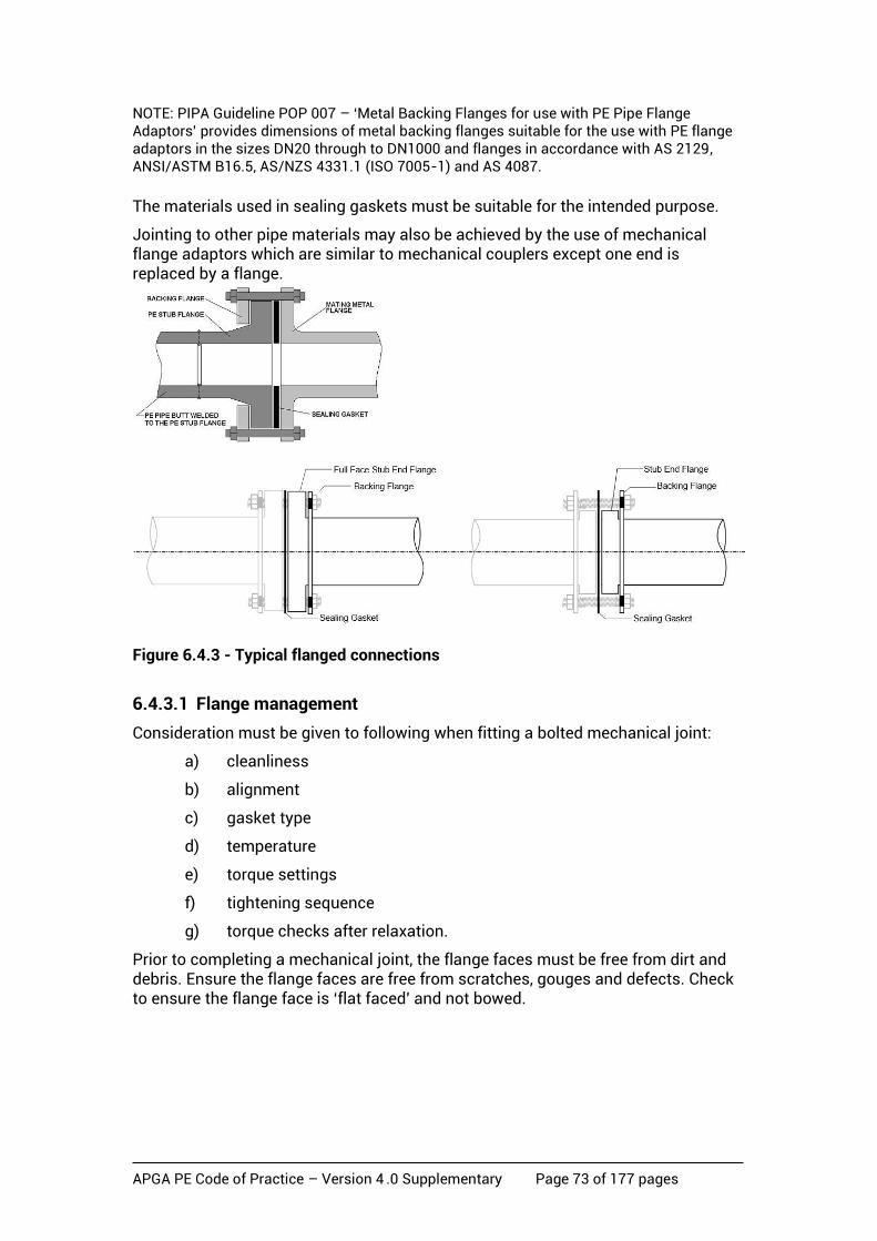
APGA PE Code of Practice – Version 4 .0 Supplementary Page 73 of 177 pages
NOTE: PIPA Guideline POP 007 – ‘Metal Backing Flanges for use with PE Pipe Flange Adaptors’ provides dimensions of metal backing flanges suitable for the use with PE flange adaptors in the sizes DN20 through to DN1000 and flanges in accordance with AS 2129, ANSI/ASTM B16.5, AS/NZS 4331.1 (ISO 7005-1) and AS 4087.
The materials used in sealing gaskets must be suitable for the intended purpose.
Jointing to other pipe materials may also be achieved by the use of mechanical flange adaptors which are similar to mechanical couplers except one end is replaced by a flange.
Figure 6.4.3 - Typical flanged connections
6.4.3.1 Flange management
Consideration must be given to following when fitting a bolted mechanical joint:
a) cleanliness
b) alignment
c) gasket type
d) temperature
e) torque settings
f) tightening sequence
g) torque checks after relaxation.
Prior to completing a mechanical joint, the flange faces must be free from dirt and debris. Ensure the flange faces are free from scratches, gouges and defects. Check to ensure the flange face is ‘flat faced’ and not bowed.
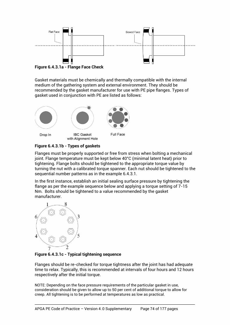
APGA PE Code of Practice – Version 4 .0 Supplementary Page 74 of 177 pages
Figure 6.4.3.1a - Flange Face Check
Gasket materials must be chemically and thermally compatible with the internal medium of the gathering system and external environment. They should be recommended by the gasket manufacturer for use with PE pipe flanges. Types of gasket used in conjunction with PE are listed as follows:
Figure 6.4.3.1b - Types of gaskets
Flanges must be properly supported or free from stress when bolting a mechanical joint. Flange temperature must be kept below 40°C (minimal latent heat) prior to tightening. Flange bolts should be tightened to the appropriate torque value by turning the nut with a calibrated torque spanner. Each nut should be tightened to the sequential number patterns as in the example 6.4.3.1.
In the first instance, establish an initial sealing surface pressure by tightening the flange as per the example sequence below and applying a torque setting of 7-15 Nm. Bolts should be tightened to a value recommended by the gasket manufacturer.
Figure 6.4.3.1c - Typical tightening sequence Flanges should be re-checked for torque tightness after the joint has had adequate time to relax. Typically, this is recommended at intervals of four hours and 12 hours respectively after the initial torque.
NOTE: Depending on the face pressure requirements of the particular gasket in use, consideration should be given to allow up to 50 per cent of additional torque to allow for creep. All tightening is to be performed at temperatures as low as practical.
APGA PE Code of Practice – Version 4 .0 Supplementary Page 75 of 177 pages
7 Inspection and Testing
7.1 Basis of section
Inspection and testing forms an integral part of the pipeline system. It ensures all parts of the pipeline including the material manufacture, design, and installation have been carried out in accordance with this Code of Practice. The Operator shall ensure that the appropriate inspections and testing are carried out during the total life cycle of the works.
7.2 Inspections and test plans
Inspection and test plans shall be designed, approved and implemented for the required parts of the works including materials handling, installation and commissioning. Inspection and test plans (ITP) shall as a minimum include:
a) description and item number of the activity
b) description of each test, examination or inspection to be performed
c) responsible persons
d) reference documents, controlling specifications and procedures
e) acceptance criteria
f) verifying documents or check sheets
NOTE: The ITP itself may also be used as a check sheet.
g) provision for hold, witness, verify and review points.
ITPs shall be applied to specified sections of the works so as to allow sign off in discrete stages, not just at final completion. ITPs shall be approved and cover all stages of the works.
7.3 Materials inspection
Pipe and fittings shall be packaged, handled and transported in accordance with the PIPA Guideline POP 005. On receipt of pipe and fittings, and before installation, inspection of materials shall be carried out to ensure:
a) correct type, size, rating and SDR of pipe and fittings
b) no damage is evident that reduces the wall thickness more than 10 per cent
c) correct identity and traceability markings are present
d) no debris is in the pipe.
7.4 Installation
Inspection and testing upon installation shall verify that:
a) correct lifting and laying equipment has been used;
b) trench bottom is free of debris, rocks or clumps that could cause damage to pipe;
c) trench depth and cover is correct to specification;
d) adequate bedding has been used where required;

APGA PE Code of Practice – Version 4 .0 Supplementary Page 76 of 177 pages
e) pipe and fittings are within specified tolerances for diameter and out of roundness;
f) correct amount of embedment is around pipe;
g) pipe is not laid up against sharp objects on wall of the trench;
h) correct backfill has been used;
i) marker tape and/or trace wire has been installed;
j) compaction of backfill is in accordance with the specification; and
k) as-built records have been completed before final backfill.
7.5 Welding/joining
Joining pipes and fittings by electrofusion or butt welding shall be to an approved joining procedure that has been qualified by destructive testing in accordance with ISO 13954 ‘Plastics pipes and fittings - Peel decohesion test for polyethylene (PE) electrofusion assemblies of nominal outside diameter greater than or equal to 90 mm’ and ISO 13953 ‘Polyethylene (PE) pipes and fittings - Determination of the tensile strength and failure mode of test pieces from a butt-fused joint’ respectively.
For electrofusion welding, an acceptable alternative method of destructive testing may be undertaken in accordance with ISO 21751 ‘Plastics pipe and Fittings - Decohesion test of electrofusion assemblies - Strip-bend test’.
Due to the simplicity of the ISO 21751 testing methodology, it is also practical for indicative checks on site (e.g. when trying new fittings, procedures, equipment or for training of the welders).
For the welding procedure qualification or production tests, the ISO 21751 testing needs to be done in a testing laboratory by competent personnel.
The acceptance criteria for ISO 13954 and ISO 21751 peel decohesion tests require the test samples to rupture in a ductile mode with the percentage of brittle failure de-cohesion being less than or equal to 33.3 per cent for each test specimen (not the overall test specimens combined). The percentage of brittle failure is determined as a ratio of the largest length of brittle failure to total length of fusion zone at the same location - refer to ISO 13954 for more information.
The acceptance criteria for ISO 13953 tensile strength test require the test samples to present a ductile failure mode, be free from defects and contamination in the weld plane, and shall have a minimum tensile strength of 90 per cent of the parent pipe.
NOTE: Qualified procedures may be grouped by diameter to reduce the amount of qualification testing. The recommended groupings are shown in Table 7.5.

APGA PE Code of Practice – Version 4 .0 Supplementary Page 77 of 177 pages
Table 7.5 Welder and welding procedure qualification groupings
Procedure qualification test diameter
Type of joining process Qualifies for sizes within range
Any ≤ DN110 Butt weld Any ≤ DN110
Any ≥ DN 125 to DN280 Butt weld Any ≤ DN280
Any ≥ DN 315 to DN 800 Butt weld Any ≥ DN 315 up to DN 800*
Any ≥ DN 800 Butt weld Any ≥ DN 800*
Any ≤ DN 110 Electrofusion weld other than a EF saddle weld
Any ≤ DN 110
Any ≥ DN 125 to DN280 Electrofusion weld other than a EF saddle weld
Any ≤ DN280
Any ≥ DN 315 to DN 800 Electrofusion weld other than a EF saddle weld
Any ≥ DN 315 to DN 800*
Any ≥ DN 800 Electrofusion weld other than a EF saddle weld
Any ≥ DN800*
Any ≤ DN 160 (carrier pipe)
Electrofusion saddle weld Any ≤ DN 160 (carrier pipe)
Any > DN 160 to DN 315 (carrier pipe)
Electrofusion saddle weld Any > DN 160 up to DN 315 (carrier pipe) *
Any > DN 315 (carrier pipe)
Electrofusion saddle weld Any > DN315 (carrier pipe)*
* Note: where a qualification range is specified, the largest diameter and lowest SDR (thickest wall pipe) shall be used to qualify the range.
The essential variables for the weld qualification shall include:
• procedure (process type: high pressure, low pressure, dual pressure)
• individual welder (training and competency)
• diameter group size as per table 7.5
• pipe thickness > 70 mm.
Qualification for individual welding machines shall be undertaken where design differences between machines may lead to unacceptable operator error.
Equipment used for welding such as butt fusion and electrofusion machines must be qualified for the diameter group size as per Table 7.5. The welder must be qualified for operating the welding machine which has been qualified for the weld procedure.
APGA PE Code of Practice – Version 4 .0 Supplementary Page 78 of 177 pages
All welders undertaking work on the pipeline shall be assessed by performing test welds on the same size groupings in Table 7.5. Destructive testing shall then be carried out in accordance with ISO 13954 or ISO 21751 for electrofusion welding, and ISO 13953 for butt fusion welding. This assessment is in addition to the competency certificate issued by an appropriate RTO.
Supplementary specialised training by the proprietor or other qualified person is a requirement for all personnel involved in welding using proprietary equipment/ methods as described in Section 6.3.3.1.
Site welding assessments may be considered approved as long as the welder has been welding the same type/group of pipe and fittings in the past 12 months.
Site welding assessments may be transferred between projects provided that:
• the welder has been welding the same type/group of pipe and fittings in the past 12 months;
• there is a record of a destructive test undertaken in the past 12 months; and
• they are approved by the Operator.
Minimum inspection that shall be carried out during electrofusion and butt welding include:
a) materials checked for damage and type;
b) clamping and alignment complies with qualified procedure;
c) cleaning and oxidised material removal of components comply with qualified procedure;
d) heating and pressures are within the qualified procedure;
e) bead shape and height of butt welds is as per Section 6 of this Code; and
f) as-built and material traceability records are completed.
7.5.1 Final construction and repair tie-ins (golden welds)
Final butt or electrofusion tie-ins (golden welds) connecting pipe sections that have already been pressure tested shall be installed in accordance with the welding jointing requirements of Section 7.5 and shall be evaluated for integrity. The methodology of evaluation shall be approved. Appendix C provides guidance on testing of golden welds.
Except in the case of emergency response, golden welds shall not be used in high use or sensitive location classes.
7.6 Personnel Quality assurance and inspection shall be carried out by competent personnel who have had appropriate training and experience, are able to produce a current competency certificate and have been approved by the Operator. Training shall have been undertaken by an appropriate RTO.

APGA PE Code of Practice – Version 4 .0 Supplementary Page 79 of 177 pages
7.7 Pressure testing
Except for components that are exempt from field pressure testing, all pipelines and components shall pass an approved pressure test in accordance with Section 8 of this Code.
7.7.1 Exemptions from a field pressure test
The following items may be exempted from field pressure testing:
a) Pipes and other pressure containing components that have been pre-tested to a pressure that is not less than that specified for the pressure test.
b) Tie-in welds made between pressure test sections after they have been pressure tested.
c) Small bore controls, instruments and sampling piping.
7.8 Visual and non destructive tests
All components of the pipeline shall be visually inspected before installation to ensure compliance with Section 3 of this Code.
Each butt weld or electrofusion weld shall be visually inspected in accordance with PIPA Guideline POP 014 before testing or commissioning.
7.9 Production testing
After the initial qualification of both EF and butt welding procedures there shall be a requirement for ongoing testing by the removal of a butt and an EF joint out of the pipeline and destructively testing them to ISO13954 or ISO 21751 for EF welding, and to ISO13953 for butt welding. The frequency of testing shall be approved by the Operator with a recommended minimum requirement of one butt and one electrofusion weld taken within the first 10 welds of the individual welder for each type (i.e. EF or butt welding). Test samples shall be taken from a range of different diameters where practically possible. If the weld complies then a sample rate of 1 in 200 for the same welder shall apply. If the production weld fails then two more welds from the same welder shall be removed for testing, if either fails to comply then an investigation is to be carried out to determine the cause and recommend action.
NOTES:
1. To effectively carry out this testing it will be necessary to have a high level of weld traceability back to the welder and weld location.
2. Data loggers can provide valuable information in assessing welds.
APGA PE Code of Practice – Version 4 .0 Supplementary Page 80 of 177 pages
8 Pressure Testing
8.1 Basis of section
All new pipelines and any part of an existing pipeline that is repaired, diverted or altered in any way shall be subject to a pressure test to validate mechanical strength and detect leakage of the pipeline prior to commissioning. A formal test procedure shall be developed and qualified prior to being used. This procedure shall clearly contain the:
• acceptance criteria
• design and operation of test equipment
• risk mitigation measures to ALARP.
NOTE: It is recognised that there must be untested joints (such as closure joints) which cannot be subject to pressure testing, but these shall be kept to an absolute minimum.
Experience has demonstrated that the risks associated with pressure testing are among the highest in the field development and construction activities associated with gathering network development.
Pressure testing organisations certified under NATA or an equivalent organisation should be considered preferentially.
The test procedure and the instruments used shall demonstrate clearly that there is no leakage that will constitute a hazard following commissioning of the tested system. The test procedure shall be established to ensure that, when the testing is carried out, the highest standards of safety are maintained throughout the test period. Adequate facilities shall be provided by the Operator to enable these standards to be met.
For a CSG PE gathering network system, pneumatic strength testing shall not be used for both gas and CSG water pipelines in exclusion zones around key facilities (e.g. compressor stations, RO plants), residences and as listed in Section 8.4.1.1.
Due to the visco-elastic nature of PE, it is not practical to conduct such tests in a manner that will ensure no pressure change. Variations of atmospheric pressure, temperature of the test fluid in the pipeline and material creep will have a significant effect on the test pressure. Therefore, it is necessary to permit some drop in measured pressure over the test period.
Consideration for volume increases due to creep occurring during the testing period will have to be made for PE pipelines. When a PE pipe is subjected to a test pressure there will be pressure decay, even in a leak free system, due to creep of the PE material.
As a result of this material behaviour, pipe testing procedures used for other materials such as steel may not be suitable for PE pipe.
The pipeline or a system of pipelines may be tested whole or in sections depending on the test pressure requirements, the length and diameter of the line, exclusion zone limitations and the spacing between sectioning valves or blanking ends.
The designer/Operator should, in the process of designing the system, give due consideration to how the pipeline system will be tested, including:
a) the number of test sections in relation to the exclusion zones
APGA PE Code of Practice – Version 4 .0 Supplementary Page 81 of 177 pages
b) the potential for reduction in size of the exclusion zones as discussed in Section 8.2 of this code
c) minimising the number of closure joints (tie-in joints).
The pipeline (or section) shall be properly supported and, if it includes non-load bearing joints, be anchored to prevent the movement of pipes or fittings during the test.
8.2 Safety
8.2.1 General precautions
The hazards involved in pressure testing shall be considered, and the following procedures shall be observed:
a) Owing to the presence of one or more undetected defects in equipment or pipeline, or for other unforeseen reasons, a rupture may occur at some stage during the application of pressure. The test procedure shall ensure that, as far as is practicable, if the test equipment or pipeline fails during the testing, there will be no possibility of injury to any person.
b) Test equipment, including flexible hoses shall be marked with their MAOP which shall not be less than twice the set pressure of the Pressure Safety Valve (PSV), if installed on the pressurising equipment, or twice the maximum pressure the system can generate. Flexible hoses shall be fit for purpose and include whip socks if required for risk mitigation.
c) A service test of temporary test equipment shall be performed prior to commencement of pressurisation.
d) Flexible hoses and their connections shall be visually examined prior to use to ensure that they are fit for their intended purpose and have a current certificate of compliance. They shall be secured and anchored by a secondary restraining device (e.g. whip check chain, hose sock or similar) to prevent movement in the event of failure.
e) Test instrumentation shall have a valid certificate of calibration from a recognised and certified testing agency.
f) Verification of testing instrumentation (i.e. gauges, recorders etc.) shall be performed in accordance with a documented procedure against a prime reference instrument that is traceable to a primary standard.
g) All flanges which are blanked for the purpose of the test shall have their full component of bolting and be of the same pressure rating.
h) Work to be undertaken at any pressure must be conducted under an approved procedure or be subject to a risk assessment.
i) Testing shall not be carried out against closed valves. Installed valves shall be open and plugged, or capped.
j) The test section should be physically isolated from any commissioned system.
APGA PE Code of Practice – Version 4 .0 Supplementary Page 82 of 177 pages
k) Normally the test section is to be buried. However, if pipework is exposed it should be secured adequately and protected against temperature variation.
l) Adequate barriers and signage shall be positioned at the limit of the primary exclusion zone, as determined in Section 8.2.3. It is recommended that barrier tape, coloured blue and white with the wording ‘Pressure Testing’, is placed at regular intervals.
m) The testing supervisor shall to ensure that all necessary precautions are taken:
• before pressurisation;
• during pressurisation;
• during de-pressurisation and before dismantling of equipment; and
• after de-pressurisation and during dismantling of equipment.
n) The impact of noise generated during pressurisation and de-pressurisation shall be considered and minimised by the controlled introduction and release of the test medium. Noise exposure limits for personnel in the area must be assessed and not exceeded.
o) Prior to commencing a pressure test a detailed Emergency Response Plan shall be available.
p) After the completion of a low-pressure test (<200 kPa as per Section 8.5.6 b), personnel shall not enter the primary exclusion zone throughout the duration of the strength test unless the test section has passed the strength test and the pressure has been reduced to MAOP or lower.
q) If the test section is being strength tested and there are indications that it is failing, authorised personnel may only enter the primary exclusion zone to check for causes as to why it has failed after the test section has been depressurised to below 200 kPa.
r) Throughout the duration of the strength test only personnel involved in the testing operation may enter the secondary exclusion zone.
s) When using nitrogen for the use of testing components, tracer gas and pre-commissioning purposes, consideration shall be given to the dangers associated with asphyxiation, high pressure and nitrogen handling, particularly for work in confined spaces. Vent stacks and pipes should be positioned at least two metres above-ground in order to achieve a safe atmosphere. A separate risk assessment shall be performed.
t) Temporary valves used for testing purposes, such as isolation or control valves, should be positioned upright as shown below.
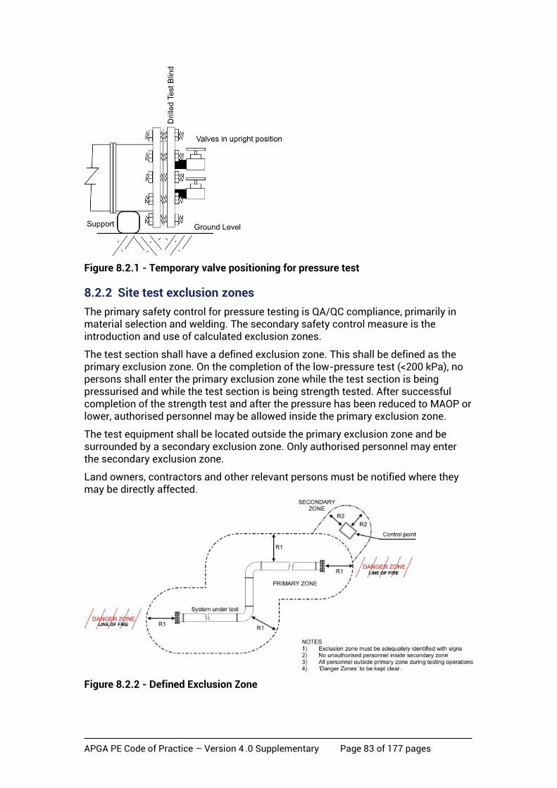
APGA PE Code of Practice – Version 4 .0 Supplementary Page 83 of 177 pages
Figure 8.2.1 - Temporary valve positioning for pressure test
8.2.2 Site test exclusion zones
The primary safety control for pressure testing is QA/QC compliance, primarily in material selection and welding. The secondary safety control measure is the introduction and use of calculated exclusion zones.
The test section shall have a defined exclusion zone. This shall be defined as the primary exclusion zone. On the completion of the low-pressure test (<200 kPa), no persons shall enter the primary exclusion zone while the test section is being pressurised and while the test section is being strength tested. After successful completion of the strength test and after the pressure has been reduced to MAOP or lower, authorised personnel may be allowed inside the primary exclusion zone.
The test equipment shall be located outside the primary exclusion zone and be surrounded by a secondary exclusion zone. Only authorised personnel may enter the secondary exclusion zone.
Land owners, contractors and other relevant persons must be notified where they may be directly affected.
Figure 8.2.2 - Defined Exclusion Zone
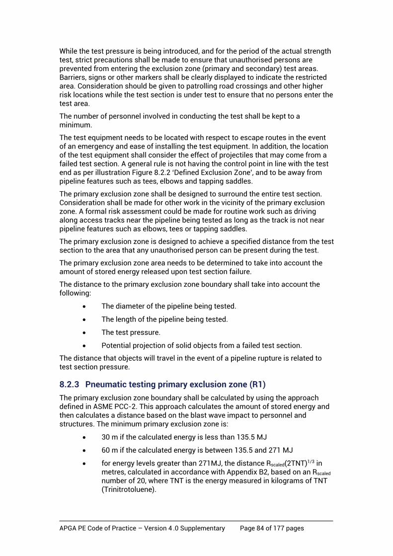
APGA PE Code of Practice – Version 4 .0 Supplementary Page 84 of 177 pages
While the test pressure is being introduced, and for the period of the actual strength test, strict precautions shall be made to ensure that unauthorised persons are prevented from entering the exclusion zone (primary and secondary) test areas. Barriers, signs or other markers shall be clearly displayed to indicate the restricted area. Consideration should be given to patrolling road crossings and other higher risk locations while the test section is under test to ensure that no persons enter the test area.
The number of personnel involved in conducting the test shall be kept to a minimum.
The test equipment needs to be located with respect to escape routes in the event of an emergency and ease of installing the test equipment. In addition, the location of the test equipment shall consider the effect of projectiles that may come from a failed test section. A general rule is not having the control point in line with the test end as per illustration Figure 8.2.2 ‘Defined Exclusion Zone’, and to be away from pipeline features such as tees, elbows and tapping saddles.
The primary exclusion zone shall be designed to surround the entire test section. Consideration shall be made for other work in the vicinity of the primary exclusion zone. A formal risk assessment could be made for routine work such as driving along access tracks near the pipeline being tested as long as the track is not near pipeline features such as elbows, tees or tapping saddles.
The primary exclusion zone is designed to achieve a specified distance from the test section to the area that any unauthorised person can be present during the test.
The primary exclusion zone area needs to be determined to take into account the amount of stored energy released upon test section failure.
The distance to the primary exclusion zone boundary shall take into account the following:
• The diameter of the pipeline being tested.
• The length of the pipeline being tested.
• The test pressure.
• Potential projection of solid objects from a failed test section.
The distance that objects will travel in the event of a pipeline rupture is related to test section pressure.
8.2.3 Pneumatic testing primary exclusion zone (R1)
The primary exclusion zone boundary shall be calculated by using the approach defined in ASME PCC-2. This approach calculates the amount of stored energy and then calculates a distance based on the blast wave impact to personnel and structures. The minimum primary exclusion zone is:
• 30 m if the calculated energy is less than 135.5 MJ
• 60 m if the calculated energy is between 135.5 and 271 MJ
• for energy levels greater than 271MJ, the distance Rscaled(2TNT)1/3 in metres, calculated in accordance with Appendix B2, based on an Rscaled number of 20, where TNT is the energy measured in kilograms of TNT (Trinitrotoluene).

APGA PE Code of Practice – Version 4 .0 Supplementary Page 85 of 177 pages
These distances are subject to increase in specific direction of failure to allow for potential projected missiles.
Appendix B2 details the method of calculating the stored energy and the safe distance in the pipeline to be used in pneumatic strength tests.
NOTE: Refer to the appropriate Companion Paper for further information.
8.2.4 Pneumatic testing secondary exclusion zone (R2)
The secondary exclusion zone boundary shall be established around the control point. The minimum recommended approach is to use the distance based on an Rscaled number of 20. In this calculation, the stored energy is the energy in the test equipment – hoses and headers. An alternative is to use an exclusion distance of 10m.
NOTE: A 100m long, 50 mm diameter hose will have an exclusion zone of less than 5m.
During testing operations, no unauthorised person will be permitted to enter this zone.
Appendix B2 details the distance calculation to be used in pneumatic strength tests.
8.2.5 Hydraulic testing primary exclusion zone for above-ground sections and open bell-holes (R1)
This distance shall be calculated with a minimum distance of 5 metres from any part of the test section. The calculation shall determine the amount of stored energy in the test section. The Operator and testing personnel will be required to ascertain the air content of the test section and determine if this is acceptable.
Appendix B3 describes the process of calculating the amount of stored energy in the hydraulic test section taking into account the additional energy resulting from the residual air content.
The minimum safe distance to be applied to the hydraulic test primary exclusion zone (R1) shall be the greater of:
a) 5m
b) R = Rscaled (2TNT)^1/3
where R = actual exclusion zone distance from test section/equipment.
Rscaled = 20 (Scaled consequence factor)
TNT = Energy measured in equivalent kilograms of TNT (Trinitrotoluene).
NOTES:
1. TNT in the above equation is the sum of stored hydraulic energy (calculated in accordance with Appendix B3) and stored pneumatic energy from residual air remaining in the test section (calculated in accordance with Appendix B3). The volume (V) used in the calculation given in Appendix B3 will have to be adjusted to match the estimated volume of residual air in the test section (e.g. 0.2 per cent of the total test section volume).
2. This reduction in the exclusion zone for hydraulic testing is based on the extremely small calculated energy content. The risk of a pneumatic blast wave, present during hydraulic tests, is only applicable to the minimal residual air component during hydraulic tests which enables reduction in the safe distance used.

APGA PE Code of Practice – Version 4 .0 Supplementary Page 86 of 177 pages
8.2.6 Hydraulic testing primary exclusion zone for buried section of pipelines (R1)
The test section shall have an exclusion zone around all above-ground or open sections. The buried section does not need an exclusion zone, however consideration shall be given to sensitive areas such as road crossings, right of ways, access tracks and populated areas. These areas should have signage stating ‘Entering Pressure Testing Area. Remain in vehicle at all times’ erected within the area of the system under pressure. In special circumstances consideration should be given to patrolling the area. At exits, the area should have signage stating, ‘Exiting Pressure Testing Area’.
NOTE: This reduction in the exclusion zone for hydraulic testing is based on the calculated energy content.
8.2.7 Hydraulic testing secondary exclusion zone (R2)
The secondary exclusion zone boundary shall be erected around the control point. The minimum secondary exclusion zone shall be 5 metres.
8.2.8 Pre-testing
Sections of pipeline in key areas may need to be pretested or tested separate to the main pipeline section. Examples are road, creek crossings, and sections near plants and houses where the impact of a failure of a pressure test is critical. The fabricated pipeline sections to be installed by trenchless construction methods, as defined in Section 5.3.3, shall be pretested in all cases. These sections can later be tied into a longer section of test section. In these cases, the exclusion zone around the pretested section can be reduced as it has previously passed a strength test.
8.2.9 Alternative safe distance calculation methodologies
ASME PCC-2 remains the minimum requirement under this Code unless the Operator independently qualifies an alternate calculation methodology which is as safe as the mandated requirement prior to use and has been verified by a qualified third party.
Use of alternatives to ASME PCC-2 would require assessment of following minimum considerations:
a) Full review of all design and constructability issues related to the network system due to be pressure tested;
b) Pressure test method to be nominated;
c) Full hazard assessment to be conducted for each location;
d) Formal risk assessment to be conducted based on the above; and
e) Calculation of stored energy based on the qualified length of pipeline test section.
8.3 Test plan
A test plan needs to be developed for all pressure tests. This plan can be a general document to cover most cases. However, in all cases the risks and hazards of the particular test need to be understood and managed.

APGA PE Code of Practice – Version 4 .0 Supplementary Page 87 of 177 pages
The testing plan shall be able to:
• ensure the implementation of all risk controls
• ensure that a JSA is completed and all items identified are adhered to
• ensure that all relevant equipment has a current calibration certificate from a recognised and certified testing agency
• ensure that all measuring equipment is located at a suitable distance from the test section to comply with exclusion zone requirements
• ensure that the EMP is followed for the disposal of the test fluids and other wastes.
The person or persons responsible for preparation of the test plan shall have appropriate qualifications and experience.
8.3.1 Approvals
The test equipment shall be approved. This approval shall include a suitable risk assessment method.
The water used in testing needs to be approved as being suitable to be used for the test and for subsequent disposal.
Potential environmental impact of loss of containment in the event of pipe rupture during testing should also be assessed.
8.3.2 Test sections
When developing the test plan, the person or persons responsible for defining the test sections should take into consideration the following:
• exclusion zone distances to boundaries;
• water sources and discharge points;
• configuration of the test system; and
• elevation of the high and low points of the system.
Where it is not feasible to pneumatically test due to constraints associated with larger exclusion zones, the pipe may be strength tested in smaller sections hydraulically and then installed within the larger test section. The larger test section may then be pneumatically tested as the sub-sections in vulnerable areas would have already undergone strength testing. This process will eliminate untested joints within the test system.
8.3.3 Testing different SDRs
Normally a heavy SDR rated pipe will be used for special crossings such as road crossings, rail and river crossings. The pipe strings are pre-tested prior to insertion and are normally incorporated into a final test.
It is common when designing the system to allow a heavier SDR at low points and special crossings as illustrated in Figure 8.3.3.
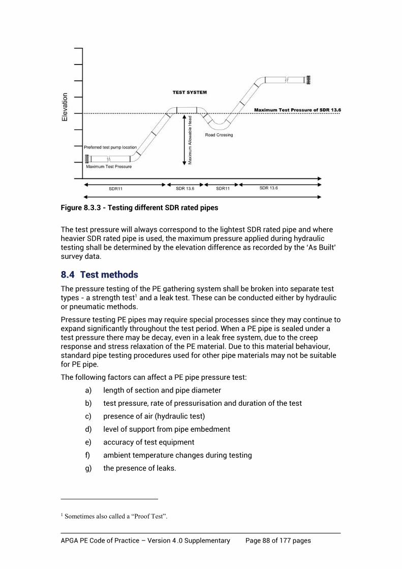
APGA PE Code of Practice – Version 4 .0 Supplementary Page 88 of 177 pages
Figure 8.3.3 - Testing different SDR rated pipes
The test pressure will always correspond to the lightest SDR rated pipe and where heavier SDR rated pipe is used, the maximum pressure applied during hydraulic testing shall be determined by the elevation difference as recorded by the ‘As Built’ survey data.
8.4 Test methods
The pressure testing of the PE gathering system shall be broken into separate test types - a strength test1 and a leak test. These can be conducted either by hydraulic or pneumatic methods.
Pressure testing PE pipes may require special processes since they may continue to expand significantly throughout the test period. When a PE pipe is sealed under a test pressure there may be decay, even in a leak free system, due to the creep response and stress relaxation of the PE material. Due to this material behaviour, standard pipe testing procedures used for other pipe materials may not be suitable for PE pipe.
The following factors can affect a PE pipe pressure test:
a) length of section and pipe diameter
b) test pressure, rate of pressurisation and duration of the test
c) presence of air (hydraulic test)
d) level of support from pipe embedment
e) accuracy of test equipment
f) ambient temperature changes during testing
g) the presence of leaks.
1 Sometimes also called a “Proof Test”.

APGA PE Code of Practice – Version 4 .0 Supplementary Page 89 of 177 pages
Long test sections may incorporate a large number of joints that need to be checked for leakage. The longer the test section the harder it may be to locate a leak – this will depend on the chosen leak test method.
The pipeline or system may be tested as a whole or in sections, depending on test pressure requirements, the length and diameter of the line, the availability of water (if undertaking a hydraulic test), and the spacing between sectioning valves or blanking ends. The pipeline (or section) shall be properly supported and, if it includes unrestrained joints, be anchored to prevent the movement of pipes or fittings during the test.
When undertaking hydraulic testing the test section shall be filled with water, taking care to purge all free air from the section. Where a motorised positive displacement pump is used for the test, consideration should be given to the installation of an effective form of pulsation damping. The pressure shall be monitored at some convenient point and the test pressure adjusted to take account of the elevation difference between the pipeline’s lowest point and the test rig. The adjustment shall be made by subtracting 10 kPa for every metre that the rig is elevated above the lowest part of the line.
The source of any leak shall then be ascertained and any defects repaired. The pipeline shall then be retested.
8.4.1 Strength test
The intent of the strength test is to prove the integrity of the pipeline and identify any large leaks or defects in the system being tested.
Table 8.4.1a Pressure test factor
Requirement Strength pressure test factor (fp)
Standard 1.25
Increased Test Pressure Section 4.5.2.2 (a) Rural or Rural Residential location Class
1.25 x f1d / f1t
Increased Test Pressure Section 4.5.2.2 (a) High Use or Sensitive Sub-location Class
1.40 x f1d / f1t
Where:
• f1d is the factor f1 at the design temperature; and
• f1t is the f1 factor at the test temperature as per Table 4.4.1.2.
Where the test factor will cause the pressure in the pipeline under test to exceed 1.25 x PN, the MAOP shall be revised in accordance with Section 4.3.5, or an alternate physical or procedural protection method chosen in accordance with Section 4.5 to ensure a pressure of 1.25 x PN is not exceeded.

APGA PE Code of Practice – Version 4 .0 Supplementary Page 90 of 177 pages
Table 8.4.1b Strength test criteria – gas pipeline hydraulic test
Hydraulic strength test gas pipeline
Acceptance criteria
Starting pressure fp x MAOP at the highest point, the lowest point shall not exceed PNx1.25. Test pressure to remain between: fp x MAOP & MAOP during test at the highest point. 6 hours minimum hold duration. P>= MAOP at highest point.
1. Structural integrity maintained for 6 hours while pressure held between fp x MAOP and MAOP at the highest point. 2. No evidence of sudden pressure drop.
Table 8.4.1c Strength test criteria – CSG water pipeline hydraulic test
Hydraulic strength test CSG water pipeline
Acceptance criteria
Starting pressure fp x MAOP at the lowest point, the highest point shall not be less than MAOP. Test pressure to remain between: fp x MAOP & MAOP during test at the lowest point. 6 hours minimum hold duration. P>= MAOP at lowest point.
1. Structural integrity maintained for 6 hours while pressure held between fp x MAOP and MAOP at the lowest point. 2. No evidence of sudden pressure drop.
Table 8.4.1d Strength test criteria – pipeline pneumatic test
Pneumatic Strength Test
Acceptance Criteria
Starting pressure fp x MAOP. Test pressure to remain between fp x MAOP & MAOP during test. 6 hours minimum hold duration.
1. Structural integrity maintained for 6 hours while pressure held between fp x MAOP & MAOP. 2. No evidence of sudden pressure drop.
NOTE: In pipeline sections where an overpressure excursion greater than 110 per cent is designed, the test pressure shall be the excursion in accordance with Section 8.4.1.2 times fp as detailed in Table 8.4.1 a.
APGA PE Code of Practice – Version 4 .0 Supplementary Page 91 of 177 pages
8.4.1.1 Strength test method considerations
There are two primary methods of pressure testing, namely hydraulic (using water as the test medium) or pneumatic (using air as the test medium).
When strength tests are required to be performed in high risk locations, hydraulic strength tests should be the preferred method of testing as opposed to pneumatic strength testing due to the incompressible nature of liquids and hence greatly reduced stored energy. High risk locations include the following:
• places where other people may be working
• process facilities
• significant road crossings
• rail crossings
• populated areas
• third-party infrastructure
• where simultaneous or conflicting operations are ongoing within the exclusion zone area.
Pneumatic strength testing in high risk locations is not a preferred method but may be selected where:
• the pipeline has tees or changes in diameter that make pigging or water filling impractical
• there are significant changes in elevation
• the location is remote
• suitable test water is not available.
Specific and thorough risk assessments shall be conducted and take the necessary actions to ensure an ALARP condition.
Consideration needs to be given to testing in larger sections which will result in less untested (golden) welds, tie-in welds and the associated risk of these untested welds.
Disposal of the test water upon completion of the pressure test needs to be considered as part of the overall pressure test process.
8.4.1.2 Test pressure
The test pressure shall be the pressure test factor as detailed in Table 8.4.1 (a) times the proposed MAOP of the pipeline for a pneumatic strength test.
For a hydraulic strength test of a CSG water system the starting test pressure is the pressure test factor times the proposed MAOP of the pipeline measured at the lowest point (elevation) of the pipeline and the pressure at the highest point shall not be less than the MAOP.
For a hydraulic strength test of a gas system the starting pressure is the pressure test factor times the proposed MAOP of the pipeline measured at the highest point (elevation) of the pipeline and the pressure at the lowest point shall not exceed the pipeline PN x 1.25.
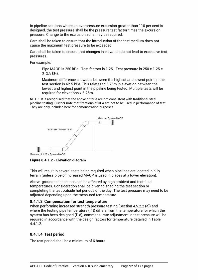
APGA PE Code of Practice – Version 4 .0 Supplementary Page 92 of 177 pages
In pipeline sections where an overpressure excursion greater than 110 per cent is designed, the test pressure shall be the pressure test factor times the excursion pressure. Change to the exclusion zone may be required.
Care shall be taken to ensure that the introduction of the test medium does not cause the maximum test pressure to be exceeded.
Care shall be taken to ensure that changes in elevation do not lead to excessive test pressures.
For example:
Pipe MAOP is 250 kPa. Test factors is 1.25. Test pressure is 250 x 1.25 = 312.5 kPa.
Maximum difference allowable between the highest and lowest point in the test section is 62.5 kPa. This relates to 6.25m in elevation between the lowest and highest point in the pipeline being tested. Multiple tests will be required for elevations > 6.25m.
NOTE: It is recognised that the above criteria are not consistent with traditional steel pipeline testing. Further note that fractions of kPa are not to be used in performance of test. They are only included here for demonstration purposes.
Figure 8.4.1.2 - Elevation diagram
This will result in several tests being required when pipelines are located in hilly terrain (unless pipe of increased MAOP is used in places at a lower elevation).
Above-ground test sections can be affected by high ambient and test fluid temperatures. Consideration shall be given to shading the test section or completing the test outside hot periods of the day. The test pressure may need to be adjusted depending upon the measured temperature.
8.4.1.3 Compensation for test temperature When performing increased strength pressure testing (Section 4.5.2.2 (a)) and where the testing pipe temperature (f1t) differs from the temperature for which the system has been designed (f1d), commensurate adjustment in test pressure will be required in accordance with the design factors for temperature detailed in Table 4.4.1.2.
8.4.1.4 Test period
The test period shall be a minimum of 6 hours.
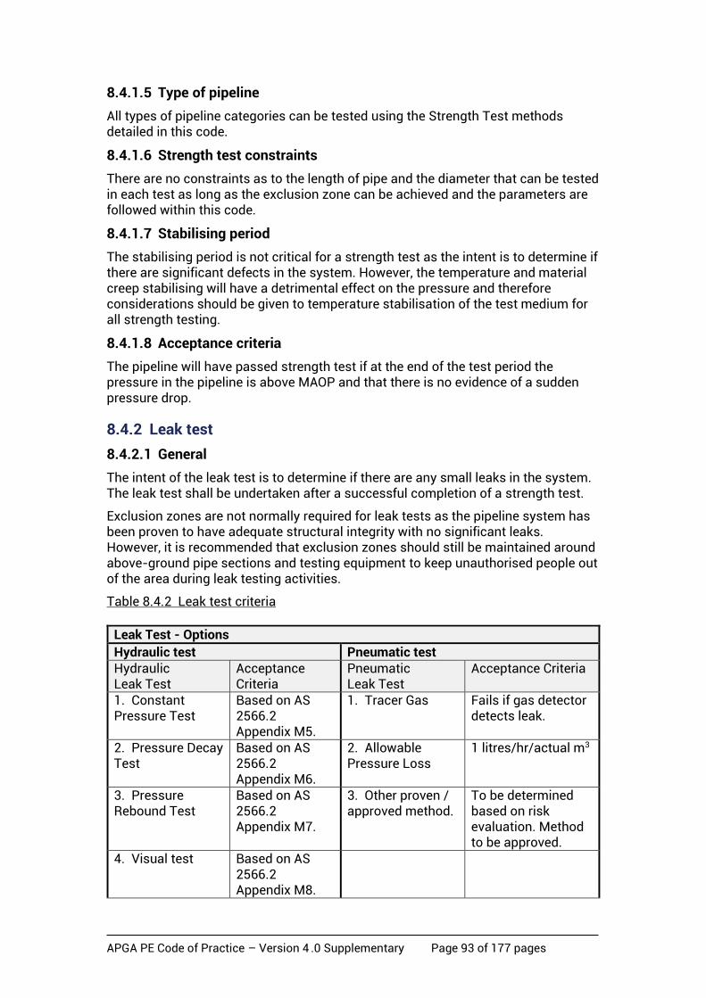
APGA PE Code of Practice – Version 4 .0 Supplementary Page 93 of 177 pages
8.4.1.5 Type of pipeline
All types of pipeline categories can be tested using the Strength Test methods detailed in this code.
8.4.1.6 Strength test constraints
There are no constraints as to the length of pipe and the diameter that can be tested in each test as long as the exclusion zone can be achieved and the parameters are followed within this code.
8.4.1.7 Stabilising period
The stabilising period is not critical for a strength test as the intent is to determine if there are significant defects in the system. However, the temperature and material creep stabilising will have a detrimental effect on the pressure and therefore considerations should be given to temperature stabilisation of the test medium for all strength testing.
8.4.1.8 Acceptance criteria
The pipeline will have passed strength test if at the end of the test period the pressure in the pipeline is above MAOP and that there is no evidence of a sudden pressure drop.
8.4.2 Leak test
8.4.2.1 General
The intent of the leak test is to determine if there are any small leaks in the system. The leak test shall be undertaken after a successful completion of a strength test.
Exclusion zones are not normally required for leak tests as the pipeline system has been proven to have adequate structural integrity with no significant leaks. However, it is recommended that exclusion zones should still be maintained around above-ground pipe sections and testing equipment to keep unauthorised people out of the area during leak testing activities.
Table 8.4.2 Leak test criteria
Leak Test - Options
Hydraulic test Pneumatic test Hydraulic Leak Test
Acceptance Criteria
Pneumatic Leak Test
Acceptance Criteria
1. Constant Pressure Test
Based on AS 2566.2 Appendix M5.
1. Tracer Gas Fails if gas detector detects leak.
2. Pressure Decay Test
Based on AS 2566.2 Appendix M6.
2. Allowable Pressure Loss
1 litres/hr/actual m3
3. Pressure Rebound Test
Based on AS 2566.2 Appendix M7.
3. Other proven / approved method.
To be determined based on risk evaluation. Method to be approved.
4. Visual test Based on AS 2566.2 Appendix M8.
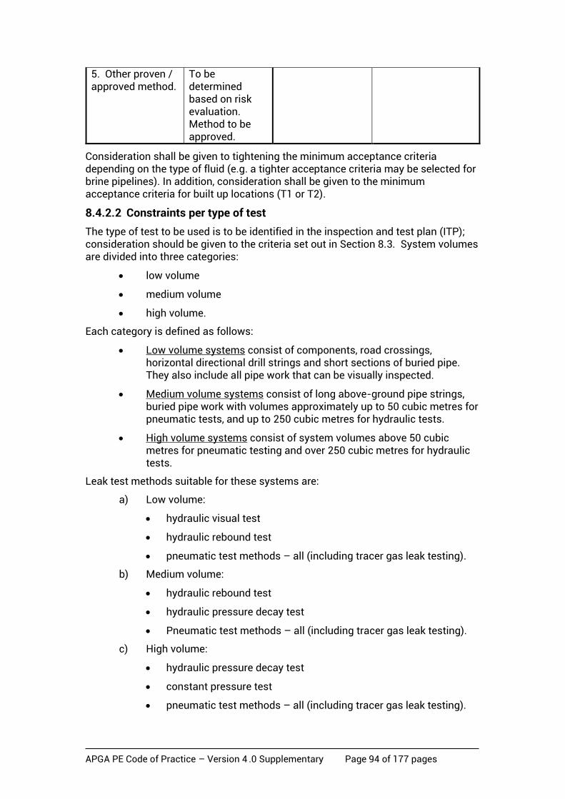
APGA PE Code of Practice – Version 4 .0 Supplementary Page 94 of 177 pages
5. Other proven / approved method.
To be determined based on risk evaluation. Method to be approved.
Consideration shall be given to tightening the minimum acceptance criteria depending on the type of fluid (e.g. a tighter acceptance criteria may be selected for brine pipelines). In addition, consideration shall be given to the minimum acceptance criteria for built up locations (T1 or T2).
8.4.2.2 Constraints per type of test
The type of test to be used is to be identified in the inspection and test plan (ITP); consideration should be given to the criteria set out in Section 8.3. System volumes are divided into three categories:
• low volume
• medium volume
• high volume.
Each category is defined as follows:
• Low volume systems consist of components, road crossings, horizontal directional drill strings and short sections of buried pipe. They also include all pipe work that can be visually inspected.
• Medium volume systems consist of long above-ground pipe strings, buried pipe work with volumes approximately up to 50 cubic metres for pneumatic tests, and up to 250 cubic metres for hydraulic tests.
• High volume systems consist of system volumes above 50 cubic metres for pneumatic testing and over 250 cubic metres for hydraulic tests.
Leak test methods suitable for these systems are:
a) Low volume:
• hydraulic visual test
• hydraulic rebound test
• pneumatic test methods – all (including tracer gas leak testing).
b) Medium volume:
• hydraulic rebound test
• hydraulic pressure decay test
• Pneumatic test methods – all (including tracer gas leak testing).
c) High volume:
• hydraulic pressure decay test
• constant pressure test
• pneumatic test methods – all (including tracer gas leak testing).
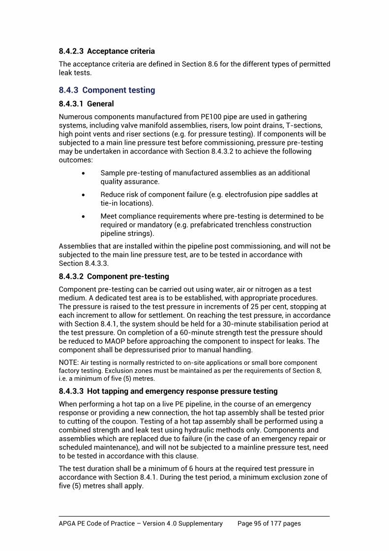
APGA PE Code of Practice – Version 4 .0 Supplementary Page 95 of 177 pages
8.4.2.3 Acceptance criteria
The acceptance criteria are defined in Section 8.6 for the different types of permitted leak tests.
8.4.3 Component testing
8.4.3.1 General
Numerous components manufactured from PE100 pipe are used in gathering systems, including valve manifold assemblies, risers, low point drains, T-sections, high point vents and riser sections (e.g. for pressure testing). If components will be subjected to a main line pressure test before commissioning, pressure pre-testing may be undertaken in accordance with Section 8.4.3.2 to achieve the following outcomes:
• Sample pre-testing of manufactured assemblies as an additional quality assurance.
• Reduce risk of component failure (e.g. electrofusion pipe saddles at tie-in locations).
• Meet compliance requirements where pre-testing is determined to be required or mandatory (e.g. prefabricated trenchless construction pipeline strings).
Assemblies that are installed within the pipeline post commissioning, and will not be subjected to the main line pressure test, are to be tested in accordance with Section 8.4.3.3.
8.4.3.2 Component pre-testing
Component pre-testing can be carried out using water, air or nitrogen as a test medium. A dedicated test area is to be established, with appropriate procedures. The pressure is raised to the test pressure in increments of 25 per cent, stopping at each increment to allow for settlement. On reaching the test pressure, in accordance with Section 8.4.1, the system should be held for a 30-minute stabilisation period at the test pressure. On completion of a 60-minute strength test the pressure should be reduced to MAOP before approaching the component to inspect for leaks. The component shall be depressurised prior to manual handling.
NOTE: Air testing is normally restricted to on-site applications or small bore component factory testing. Exclusion zones must be maintained as per the requirements of Section 8, i.e. a minimum of five (5) metres.
8.4.3.3 Hot tapping and emergency response pressure testing
When performing a hot tap on a live PE pipeline, in the course of an emergency response or providing a new connection, the hot tap assembly shall be tested prior to cutting of the coupon. Testing of a hot tap assembly shall be performed using a combined strength and leak test using hydraulic methods only. Components and assemblies which are replaced due to failure (in the case of an emergency repair or scheduled maintenance), and will not be subjected to a mainline pressure test, need to be tested in accordance with this clause.
The test duration shall be a minimum of 6 hours at the required test pressure in accordance with Section 8.4.1. During the test period, a minimum exclusion zone of five (5) metres shall apply.
APGA PE Code of Practice – Version 4 .0 Supplementary Page 96 of 177 pages
The test section should encompass the branch saddle, isolation valve and tapping equipment. The exceptions are small bore tapping saddles (OD≤63 mm), normally used for bleed or drain. Testing of such components can be performed in accordance with Section 8.4.3.2.
8.5 Strength test
A strength test requires a written test procedure which shall address:
a) installation of test equipment
b) pressure test requirements
c) pressurisation of the network pipeline
d) maximum allowable test section inlet temperature
e) pressure test
f) test pass/fail assessment
g) de-pressurisations of pipeline
h) test records.
8.5.1 Tools and equipment
The following tools and equipment are required:
a) Test pressure gauges and temperature measuring devices calibrated by a recognised and certified testing agency.
NOTE: Test pressure gauges shall be sensitive enough to accurately measure pressure change required by the acceptance criteria. Digital gauges with ±1 kPa sensitivity should be used. The measuring devices shall be calibrated at a minimum of 12 monthly intervals
b) Pressure rated hoses equipped with hose restraint.
c) Pressure test warning signs, barricading.
d) Approved test headers.
e) Air compressor with oil filter/separator and cooler or suitable supply of water, meters and pump.
f) Silencer or muffler for discharging air during de-pressurisation of pneumatic tests.
g) Flexible hoses shall include whip sock protection.
The test procedure shall be fully documented and approved by the Operator. This approval may include a formal hazard assessment or other suitable risk assessment method.
The temperature of air or water being injected into the pipeline may be significantly higher than ambient conditions. Consideration must be given to the installation of an after-cooler on the compressor to prevent overheating when using a pneumatic strength test and air temperature measurement during pressurisation.

APGA PE Code of Practice – Version 4 .0 Supplementary Page 97 of 177 pages
Figure 8.5.1a - Typical certified test header
Figure 8.5.1b - Test header/ pig catcher
8.5.2 Installation of test equipment
Suitable test equipment shall be connected to the pipeline. Requirements include:
a) The location of the test equipment shall consider suitable escape
routes in the event of an emergency.
b) Test equipment shall be located in accordance with the exclusion zone
detailed in this code.
c) The pipeline shall be restrained against movement. Ideally the ends of
the pipeline being tested should be backfilled.
d) Exposed pipe should be shielded from direct sunlight during testing
operations. This can be achieved by using a suitable shading material
(not black).
e) The test equipment shall be checked by the Operator and a service test
carried out on the temporary test equipment prior to the introduction of
pressure.
f) Suitable warning notices shall be prominently displayed at the
boundaries of the exclusion zone.
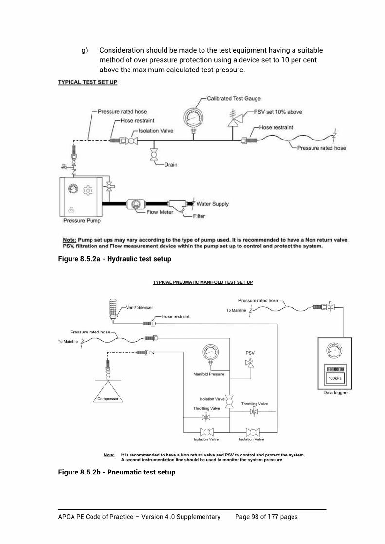
APGA PE Code of Practice – Version 4 .0 Supplementary Page 98 of 177 pages
g) Consideration should be made to the test equipment having a suitable
method of over pressure protection using a device set to 10 per cent
above the maximum calculated test pressure.
Figure 8.5.2a - Hydraulic test setup
Figure 8.5.2b - Pneumatic test setup

APGA PE Code of Practice – Version 4 .0 Supplementary Page 99 of 177 pages
8.5.3 Pressure test requirements
8.5.3.1 Test Pressure
The test pressure shall be as defined in Section 8.4.1.2.
8.5.3.2 Test temperature
Refer to Section 8.4.1.3for test temperature compensation.
8.5.3.3 Temperature stabilising period
Test fluid is being introduced into the pipeline being tested may be a different temperature to the ground temperature. A suitable time needs to be allowed for the test fluid in the pipeline to stabilise. The operator shall ensure that temperature stabilisation has been achieved.
As PE is an insulating material, significant time is required to ensure that the fluid inside the pipeline is similar to ground temperature. This is critical for the leak test if it is being conducted as part of the strength test.
If a tracer gas leak test is being conducted, temperature stabilising is not critical.
Appropriate temperature measurements may need to be carried out.
8.5.4 Strength test period
A six-hour strength test period is required.
8.5.5 Filling – hydraulic test only
The objective is to fill the pipeline with water to ensure that residual air content in the section is minimised. This may be controlled by using a pig propelled with water to expel the air or by the release of air through air valves at high points in the pipeline. Consideration should be given to elevations and where required a back pressure used to control the pig speed.
Where pigging is not a viable option due to short sections of pipe, dual diameter pipe lines or large volume systems, filling is to be conducted so that all air is expelled from all possible high point vents.
8.5.6 Pressurisation of piping
During pressurisation and hold period the following shall be observed:
a) The test fluid shall be introduced into the test section in a controlled manner.
b) At a low pressure (<200 kPa), after allowing a short stabilisation period at this pressure, check all above-ground components for signs of leakage.
c) While the pipeline section is pressurised, no unauthorised person shall be inside the primary exclusion zone. After the initial low pressure test no persons are to enter the primary exclusion zone until the pipeline has passed the test and the pressure is reduced to MAOP or lower.
d) Line valves shall not be operated.
e) Backfilling or excavation shall not be carried out within the exclusion zone area or anywhere else along the section of pipeline under test.
APGA PE Code of Practice – Version 4 .0 Supplementary Page 100 of 177 pages
8.5.7 Strength test procedure
The following shall be carried out while the pipeline is being subjected to the pressure test:
a) Following the period of temperature stabilisation, the initial pressure reading shall be taken.
b) A further pressure reading shall be taken at the end of the strength test period and the apparent volume loss shall be determined. Intermediate pressure readings shall also be taken during the test period or alternatively, a continuous chart or electronic recording of the test pressures may be taken.
c) The supervisor responsible for the pressure test shall be present at the beginning and at the end of the pressure test to witness whether or not the test section has successfully passed the test and this shall be recorded on the test certificate.
8.5.8 Test pass/fail assessment – strength test
The pipeline will have passed strength test if at the end of the test period the pressure in the pipeline is above MAOP and that there is no evidence of a sudden pressure drop. After the successful completion of the strength test the pipeline will then be subject to a leak test process.
8.5.9 De-Pressurisation
8.5.9.1 Pneumatic test
After the test, the pipeline shall be de-pressurised in accordance with approved test procedures under the supervision of a competent person.
a) The air will be released from the test system. This process will be controlled from the control point;
b) Due to the hazards in venting air, appropriate PPE will be required;
c) Measures shall be taken to minimise noise generated during de-pressurising and its impact on the public and other personnel;
d) The testing operator shall confirm that the pressure has been reduced over the entire pipeline under test before further work can proceed within the designated test area.
8.5.9.2 Hydraulic test
After testing, the pipeline shall be de-pressurised and then de-watered (if required) in accordance with approved test procedures under the supervision of a competent person.
a) The water is to be released from the test head located at the control point.
b) Pressurised water is to be discharged in a controlled manner and rate as dictated by the test procedure.
c) Considerations should be given to the discharge point.
APGA PE Code of Practice – Version 4 .0 Supplementary Page 101 of 177 pages
d) Dewatering for gas pipe shall be carried out by driving pigs towards the discharge end of the pipeline using compressed air. This may not be required if it is intended for CSG water service.
e) A competent person shall confirm that the pressure has been reduced over the entire pipeline under test before further work can proceed within the designated test area.
8.5.9.3 Acceptance criteria
The pipeline will have passed strength test if at the end of the test period the pressure in the pipeline is above MAOP and that there is no evidence of a sudden pressure drop.
8.6 Leak test The following principles apply to the design, conduct and acceptance of a leak test:
• A pipeline shall not contain a detectable leak.
• Due to the compressibility of air (pneumatic test only) and pressure fluctuations due to the effects of creep, temperature and barometric pressure, it is possible to have a leak on a system which will not be apparent on the test equipment. Therefore, when considering the test duration the following should be taken into account:
a) volume of the system
b) ambient and ground temperatures
c) barometric pressures
d) creep (relates to pipe SDR and material).
Pressure drop due to creep depends upon the pipe material, ambient temperature, SDR, any previous stress history and the degree of restraint offered by the backfill. It does not vary with pipe volume.
If the temperature of the gas in the pipeline being tested changes there will be a gain or loss in the recorded pressure in the pipeline. This effect can be calculated and if necessary the difference in pressure due to temperature can be added to the total pressure loss effect.
8.6.1 Hydraulic visual test
A visual test can be applied for specific above-ground sections of a pipeline. These generally are component tests, special crossings that are tested before being installed if the consequence of failure is significant.
In this visual test, the pipeline has previously passed the six-hour strength test. The pressure is then reduced to the design pressure and then inspected for leaks. The test section shall be visually inspected for leakage at all joints, fittings, valves and all connections
Consideration shall be given to ensuring the visual tests are not conducted on pipelines during rain or in in wet conditions.
8.6.1.1 Procedure
This test can be applied to any length of section as long as the section can be fully inspected visually at all joints, components and across the entirety of the section.

APGA PE Code of Practice – Version 4 .0 Supplementary Page 102 of 177 pages
• Pressurise the pipe to the test pressure and then isolate.
• On completion of the strength test reduce pressure to MAOP.
• Visually inspect the test section for leakage at all joints, fittings, valves and connections.
• Pressure gauges shall be installed and checked to ensure that the pressure has not fallen indicating an undetected leak.
• Where no leak has been detected, a vent valve can be opened and the test section drained to a suitable location.
8.6.1.2 Acceptance criteria
The test section shall be visually inspected for leakage at all joints, fittings, valves and all connections. If no leaks are present then the section will be deemed acceptable.
8.6.2 Pressure rebound test
The pressure rebound test is predominantly for low volume systems. Consideration should be given to the volume of the pipeline, pump capacity and more importantly the ability to discharge a volume of water quickly in order to achieve the rebound result; this is critical to achieve a satisfactory test. Consideration should also be given to the volume of the pipe and the sudden discharge of water to ensure a ‘hammer effect’ does not occur. The rebound procedure is a rapid means of testing low volume systems and should normally be completed in a relatively short time. Details of this test method are described in Appendix B4.
8.6.3 Hydraulic pressure decay test
This test is suitable for Medium or Low Volume Systems and is recommended for volumes up to 50m3. The pressure decay test is based on a three point analysis test procedure. The test duration is based on the pressurisation time it takes to raise the pressure from head pressure to CTP (load time).
A pressurisation pump that has a high volume output capacity will be needed to ensure the test is completed in reasonable time. The test time is calculated on 15 x load time and should be completed within 1-12 hours. The procedure is based on a pressure decay curve and consideration should be given to air inclusion and the type of backfill within the system as this could affect the end result.
Details of this test method are described in Appendix B5.
8.6.4 Hydraulic constant pressure test
This test method can be used for all systems and is based on the constant pressure (water loss) method for visco-elastic pressure pipelines.
For plastics pipes that are subjected to internal pressure, there will be a progressive drop in that pressure due to creep. Accordingly, it may be difficult to assess whether a pipeline is leaking or simply subject to creep. In order to overcome this difficulty, this method is based on the principle that if the pressure is held constant, there will be a linear relationship between hoop strain and logarithmic time.
APGA PE Code of Practice – Version 4 .0 Supplementary Page 103 of 177 pages
Variables such as pipe stiffness and soil compaction are irrelevant, as the test result is based on actual performance during the test. Temperature may be considered constant, as with other test methods, unless special conditions exist.
The constant pressure test is suitable for large volume systems where several kilometres of pipe can be tested at once. On completion of the line fill the system should be pressurised to CTP, the test section isolated and allowed to stabilise for a 12-hour period. It is recommended that this is carried out overnight to allow pressure stabilisation due to creep and temperature variations. On completion of the 12-hour stabilisation period, a 5-hour constant pressure test shall be conducted where water is added to maintain CTP and the volumes added are recorded. The test shall be deemed acceptable, and the constant pressure test completed, when there are no pipeline component failures, no visible leakage, and ΔV(5h–4h) ≤ 0.55ΔV(3h–2h) + Vall (in accordance with Appendix B6.3).
Details of this test method are described in Appendix B6.
8.6.5 Tracer gas test
Tracer gas surveys are normally conducted as a leak test on completion of the strength test using an approved gas which has traceable capabilities. At present the three main tracer gases available are:
• helium (usually 1 per cent in nitrogen)
• nitrogen 95 per cent / hydrogen 5 per cent mix
• methane (CSG).
The acceptability of this method shall be tested by suitable trials. The trial shall take into account the time taken for the tracer gas to travel from a leak in the pipeline to the surface and that the pressure in the pipeline of the tracer gas mix and the detection equipment is appropriate to locate the leak. Environmental conditions such as wind and rain as well as the speed of travel over the pipeline under test need to be considered.
For existing systems where the ground has fully compacted over long periods of time, consideration should be given to the time for tracer gas to permeate though the ground. In some circumstances, further planning may be required where sniff tubes are inserted at either side of road/ river crossings and paved areas, and inserted at strategically placed points along the system, especially in the vicinity of vulnerable areas such as welded and mechanical joints.
When planning a tracer gas survey consideration should be given to the type of tracer gas used. For example, the use of methane as a tracer gas may incur problems when a leak has been detected and the system may require de-commissioning with an inert gas to carry out the repair.
The tracer gas shall be introduced into the system at the manufacturer’s recommended concentrations. The entire system will require a full purge to ensure the gas is uniformly distributed and the system pressure is a minimum of 100 kPa. Consideration should be given to the soak time as the higher the pressure the quicker the tracer gas will permeate through the ground. After a suitable time has elapsed to allow the tracer gas to permeate through the ground, a tracer gas survey shall be conducted by passing a suitable gas detector over the surface of the ground above the pipeline to detect any leakage. Careful planning is required to survey the entire system and to ensure that the speed of the detector allows the capture of all leaks. A typical manufacturer’s recommendation is that this speed be
APGA PE Code of Practice – Version 4 .0 Supplementary Page 104 of 177 pages
no more than 2.5km/hr. It is good practice to have marker pegs along the route of the system to guide operators as to direction.
The gas detector used shall be suitable for this application and calibrated for the desired tracer gas application. Attention should be given to untested joints, sealed roads and pathways where a snoop tube is normally inserted above the joint and at either side of the road crossings.
The system will pass the leak test if no detectable leaks are located with the gas detector.
When using nitrogen in leak testing, the danger of asphyxiation needs to be taken into account, especially when working in confined spaces. Vent stacks and pipes should be positioned at least 2 metres above-ground in order to achieve a safe atmosphere. Personal gas monitors shall be carried by operators during this testing.
8.6.6 Pneumatic pressure decay test
In order to achieve an acceptable pneumatic pressure decay test, the volume should be kept as low as possible as leaks will be more apparent. Generally, all tests on pipelines with large volumes should be held to a minimum leak test period of 24 hours. This will result in a full temperature cycle of the test section to be completed.
The longer the test period, the more certain the detection of leaks, so for very large volume systems the duration of the test may need to be extended.
8.6.6.1 Leakage effects
Any leak on a pipeline will result in a loss of pressure. However, the effect of small leaks can be masked by creep and temperature effects.
Therefore, the duration of the test needs to be of sufficient time to determine if any leaks are present.
8.6.6.2 Acceptance criteria
The total pressure loss or gain over the test period is related to the temperature change, creep and leakage of the test fluid. When leak testing over long durations, pressure will normally follow the trend of the barometric and internal pipe temperature as the elasticity of the pipeline will be significantly less at lower pressures.
The acceptable volume loss is 1 litre/hr/actual m3 volume of test fluid.
NOTE: The word ‘fluid’ in this context means air or other gaseous medium.
Appendix B1 details the calculation process for this test method.
8.6.7 Other proven/approved methods
Other methods of leak detection including acoustic testing are available or are being developed. In order to use any of these methods, the acceptable criteria need to be approved including verification of contractor competency as well as method verification by technical assessment and testing.
8.7 Test records
Test report sample sheets can be found in Appendix B7. A test report shall include as a minimum the following details:
APGA PE Code of Practice – Version 4 .0 Supplementary Page 105 of 177 pages
a) Test limits and identification of the section of pipeline being tested including location, length, diameter, SDR and material.
b) Date and times the test was performed.
c) Specified MAOP.
d) Test pressure at the start and at the end of the strength test.
e) Pressure recorder chart or data logger readings.
f) Details of hold periods and stabilisation times.
g) Temperature of the pipeline where relevant.
h) Statement that the section of pipeline under test has passed or failed the strength and leak test requirements showing relevant calculations.
i) Name and signature of the person validating the test.
8.8 Pressure test failure
If a pipeline fails the pressure test it shall be repaired and subjected to a further full pressure test prior to being commissioned.
8.9 Qualification and assessment of a pressure test procedure
The pressure testing procedure for testing PE pipelines shall be approved by the Operator. The test procedure shall be based on this Code and address all operational and safety issues.
Quality and WHS specialists of or contracted by the Operator shall have input into the development of the pressure test procedure. This is to ensure that all hazards associated with pressure testing have been mitigated to as low as reasonably practicable (ALARP) through the implementation of identification, evaluation and control methods.
The Operator shall provide sufficient resources to ensure that relevant information, instruction, training and supervision are available to conduct all work activities safely. The test procedure shall be assessed and monitored to ensure that it complies with the requirements of this Code. It shall be reviewed on a regular basis.
8.10 Qualification of pressure test personnel
The pressure test operator and all relevant personnel included in the work permit shall pass an approved pressure test course before being permitted to conduct a test. This course shall cover all relevant elements of this Code of Practice.
The person conducting the pressure tests may also be assessed by the Operator prior to conducting any tests. This assessment may include a practical assessment of the person’s skills and may need to be repeated from time to time.
APGA PE Code of Practice – Version 4 .0 Supplementary Page 106 of 177 pages
9 Records Management
9.1 Basis of section
Primarily, the purpose of records is to preserve:
a) historical information required for the safe operation and maintenance of the network over the network’s life;
b) objective evidence of compliance with, and effectiveness of, the network management system (NMS) and safety management system; and
c) records of decision-making and approvals.
9.2 Design, construction and commissioning records
During the design stage, receipt of materials for the network, and network construction, the Operator shall obtain, prepare and keep current, records of the following:
a) safety management studies or risk assessments conducted
b) hazard and operability study records
c) design basis
d) project specifications and data sheets
e) the traceability of all materials and components including all test results and inspection reports
f) all tests and inspections that are required to verify the integrity of the network in accordance with this Code of Practice
g) the required MAOP
h) all drawings, as built and alignment (developed in accordance with AS 1100.401) relating to the network and facilities
i) the condition of the internal and external surfaces
j) operation procedures that form part of the design
k) a list of the authorities that have granted operating permits, and land-holders through whose land the network passes, including contact history and title information
l) a list of other easements (especially easements for other networks, power lines and communications cables) through which the network passes, their contact details and other relevant information
m) records of network sections or components identified as potentially high risk in an emergency
n) commissioning records
o) quality assurance records and traceability
p) safety and environment records
q) approvals and correspondence with regulatory authorities.

APGA PE Code of Practice – Version 4 .0 Supplementary Page 107 of 177 pages
9.3 Operation and Maintenance Records
The Operator shall prepare a records management plan. The plan shall detail the records to be obtained, the records to be retained, storage methods and procedures to maintain currency of the records, until the abandonment of or removal of the network. The plan shall be approved.
Records that shall be included in the plan are the following:
a) Records required due to operating condition changes.
b) Historical NMS plans and procedures.
c) Any approved change to operating conditions, engineering investigations and any work carried out in connection with any changes to operating conditions.
d) Any modifications to the maps, charts, plans, drawings and procedures, which are required to allow the procedures to be properly administered (e.g. exposure to the public, changes in design and operating conditions including brownfield tie-ins and gathering extensions).
e) Details of any deformation, damage or other anomalies.
f) Details of any leaks, ruptures or other loss of containment events.
g) Routine inspections, and inspections and testing carried out when cutting into a network or making hot taps.
h) Repairs and maintenance work to networks.
i) Details of inspections of internal or external network condition.
j) Correspondence with statutory and regulatory authorities.
k) Safety management study or risk assessment reviews.
l) Incidents and subsequent preventive actions.
m) Operation and maintenance personnel competency details and training records.
n) MAOP review documents.
o) Location class review documents.
p) Reports on landholder and third-party liaison and the information given.
q) Records of emergency response exercises, the actions arising, and the completion of those actions.
r) Records of any pressure excursions as a result of fit for purpose design under Section 4.6 including the location, time, date and duration of the excursion and any effect on pipeline life.
The following records shall also be prepared and retained for a minimum of five (5) years:
• necessary operational data
• network surveillance patrol reports.
NOTE: Legislative obligations may result in increased record retention durations .
APGA PE Code of Practice – Version 4 .0 Supplementary Page 108 of 177 pages
9.4 Abandonment records
The Operator shall document the archiving or disposal of records associated with an abandoned network.
A record should be kept of all abandoned networks that remain in-situ, to prevent possible mistakes in identifying an abandoned network as an operational network.
The following minimum information should be recorded:
• location;
• pipeline identification number;
• abandonment plan details;
• pipeline diameter and SDR;
• type of service;
• date constructed; and
• date abandoned or decommissioned.
9.5 Records management and document control The Operator shall establish procedures for the identification, collection, storage and disposal of records pertinent to the NMS and to the achievement of the objectives of this Section. Procedures shall cover electronic as well as paper-based records. As a minimum, the following shall be addressed:
• the records to be retained;
• the retention period of each record type;
• the records storage and preservation methods (e.g. paper based, electronic storage, GIS etc);
• record update and maintenance procedures; and
• audit schedule. The Operator should ensure that appropriate records are identified, retained, managed and recorded in the records management plan. In addition to the requirements of Section 9.3, the records management plan should address the above requirements as a minimum.
The Operator shall obtain and maintain records that are necessary to:
• safely operate and maintain the network;
• demonstrate compliance with this Code of Practice and relevant legislation;
• identify decisions made and actions taken by the Operator; and
• confirm the fitness for purpose of the network at any stage of the network operating life.

APGA PE Code of Practice – Version 4 .0 Supplementary Page 109 of 177 pages
10 Commissioning
10.1 Basis of section
Commissioning shall always be the responsibility of the Operator, and should normally follow immediately after acceptance pressure testing (see Section 8) and other pre-commissioning activities. The integrity of the pipeline shall be established through an inspection testing program undertaken concurrently with construction. The Operator shall ensure that inspection and testing are undertaken as necessary during manufacture, transport, handling, welding, pipeline construction and commissioning to ensure that the completed pipeline complies with the engineering design, this Code of Practice, relevant Standards, and has the intended quality and integrity.
10.2 Commissioning plan
The Operator shall prepare a commissioning plan which will detail the persons to be involved in the commissioning and their responsibilities.
10.3 Commissioning personnel
10.3.1 General
The Operator shall appoint a suitably qualified Commissioning Manager who will direct the commissioning processes.
The Commissioning Manager shall ensure that all personnel responsible for commissioning are suitably experienced and take relevant precautions required when working on the live gas pipeline facilities.
The Commissioning Manager is also responsible for coordinating activities between all associated groups involved with the commissioning process including communication and interaction with other contractors and operating plant, and has sighted that all pre-commissioning documentation is completed prior to commissioning. Field staff provided by the operating authority will be directed by the Operator.
10.3.2 Installers
Installers shall be generally required to test and inspect all products, materials, equipment, installation and workmanship included in the works covered by the project specification to prove compliance with the specification requirements and to provide all equipment, materials, water and power supplies required to carry this out.
Testing includes pre-commissioning, field testing and performance testing of each item of the whole installation.
10.3.3 Commissioning sign-off
When satisfied that all activities and final checks are complete, the Commissioning Manager shall sign off the necessary paperwork at the end of commissioning and hand over the commissioned system to the Operator for operation.
APGA PE Code of Practice – Version 4 .0 Supplementary Page 110 of 177 pages
10.4 Plans and procedures
The Commissioning Manager shall prepare a plan and procedures document covering all inspections and tests required by this Code of Practice and the engineering design. A risk workshop shall be considered a key element in this planning process, although this may be combined with the associated pre-commissioning risk assessment/workshop. Inspections and tests shall be made in accordance with the documentation. Corrective actions shall be taken where an inspection or test reveals that specified requirements are not satisfied, with specific persons made accountable to ensure these actions are undertaken in a timely manner.
Commissioning procedures first require all pre-commissioning documents to have been completed and signed off prior to commissioning commencing.
Pre-commissioning, commissioning and start-up are the responsibility of the commissioning team under the direction of the Commissioning Manager.
Assistance from the Operator during the commissioning process is essential for a smooth handover to operations.
Commissioning is broadly defined as the range of activities that is required between mechanical completion of the plant and handover of the plant for operation. Commissioning involves introduction of process fluids and electrical power into plant, and the functional and performance testing of all equipment and systems prior to handover.
Commissioning will involve a phased approach, which will consist of:
a) pre-commissioning
b) component commissioning
c) system commissioning.
Pre-commissioning and component commissioning activities normally involve the preparation of the plant for system commissioning and operation. In some instances however, as the plant services are required for component commissioning, component commissioning and system commissioning may occur at the same time.
Pre-commissioning and component commissioning tasks may be performed by either the mechanical or electrical contractor, suppliers of packaged equipment or the commissioning team, and may be performed prior to the plant being handed over from the construction contractors. The extent to which the construction contractors perform the commissioning tasks is detailed in their respective construction contract and scope of work.
Post-handover of the plant to the commissioning team, the mechanical and electrical installation contractors may be included in the overall commissioning team.
At any time during the work, if the work parties identify any unforeseen risks, work shall cease and the Commissioning Manager shall be notified and shall take the appropriate actions.
The Commissioning Manager shall advise the work teams of permission to proceed.

APGA PE Code of Practice – Version 4 .0 Supplementary Page 111 of 177 pages
10.5 Safety and environmental precautions
10.5.1 Safety
The purging and commissioning of the pipeline must be performed in a safe and efficient manner with every precaution taken to ensure the continued safety of all personnel, property and equipment.
All operations conducted during the course of commissioning shall be in accordance with the safety requirements specified by the following documents:
• relevant government regulations
• the construction network management system for the relevant field where the commissioning is to take place
• the operations network management system (NMS) for the relevant field where the commissioning is to take place.
All work shall be carried out under the Operator’s NMS system. The Operator shall have the responsibility to ensure that these procedures are developed with safety as the prime concern. It is essential that all personnel involved in construction, shutdown, commissioning and in eventual operation of the system being commissioned know and understand:
a) plant safety rules
b) personal protection requirements
c) fire control and emergency procedures
d) fire prevention and control equipment
e) permit to work system
f) emergency management response procedure
g) network management system.
A ‘safety tool-box meeting’ including all parties involved shall be held at the beginning of each day during the commissioning and at other times as needed.
Each commissioning team member shall have the responsibility to thoroughly read and understand the fundamental processes of the commissioning of the pipeline and to highlight any activity that is unclear or considered unsafe. Commissioning activities shall be suspended immediately on any safety issues/concerns being raised by any person during the process.
A permit system shall be implemented during the commissioning process. This system consists of the following procedures:
• permit to work system
• JSA
• lock-out/tag-out system.
Any planned deviation shall be clearly identified and communicated to site personnel.
From the start of commissioning, all work must be done to the Work Permit and Danger Tag Procedure. Electrical system lockout or tagging shall also be in force.
APGA PE Code of Practice – Version 4 .0 Supplementary Page 112 of 177 pages
With several trades testing equipment for faults, this method is the only way of ensuring a safe transition from plant construction to plant operation.
All operating safety and personnel safety equipment must also be in place and functional at this stage. Where relevant ‘No Smoking’ and wearing of protective safety equipment regulations must be brought into force at this stage and the work permit system must include permits for ‘Hot work’.
Each member of the commissioning team shall clearly understand that the existing installation or other infrastructure associated with the new pipeline is critical to the safe and secure operation of the pipeline system. All personnel involved in the commissioning operations shall be adequately trained and experienced with the relevant tasks.
A commissioning workshop shall be held prior to the commissioning work commencing at which all the associated risks shall be identified and to make clear these aspects.
The Commissioning Manager or delegate shall also conduct safety/toolbox meetings at the site with all parties involved with the commissioning process present. Toolbox meetings or job safety analysis meetings must be conducted prior to any critical or new operation.
Written commissioning procedures shall be developed to ensure that all commissioning team members are fully aware of the hazards associated with pipeline commissioning and what measures are necessary to make the activities safe to perform.
To ensure all sites involved in the commissioning process remain safe and secure during natural gas purging and pressurising procedures, all other work activities associated with the pipeline being commissioned shall normally be suspended until final commissioning of the section has been completed. Any exceptions shall only occur under strict permit conditions.
The Commissioning Manager shall notify all appropriate parties of the start and completion of commissioning activities.
10.5.2 Emergency response
Detailed emergency response procedures shall be documented in the site specific emergency response plan. It shall be made clear that the protection of personnel is paramount and that no attempt shall be made to protect or salvage equipment at the risk of personnel.
10.5.3 Environment
All commissioning operations conducted shall be in accordance with the relevant environmental management plan.
All persons involved with the commissioning operation shall be formally inducted before entering the work site.
Any site-specific concerns regarding environmentally sensitive areas should be adequately communicated making clear all required actions at each toolbox meeting.

APGA PE Code of Practice – Version 4 .0 Supplementary Page 113 of 177 pages
10.6 Readiness for operation
10.6.1 Contaminants
No pipeline shall be placed in service before it has been cleaned of contaminants, before it has satisfied test requirements and, in the case of CSG water pipelines, before the quality of water supplied from the pipeline has met the Operator’s standards.
Possible contaminants include:
a) materials that enter the pipes and fittings during storage and transport
b) construction debris
c) materials introduced during construction, e.g. lubricants used with elastomeric seal joints
d) bacterial contaminants, which often colonise other contaminants.
10.6.2 Actions
All actions arising from the commissioning and/or pre-commissioning risk workshop(s) shall be implemented in a timely manner and the implementation documented. Where ongoing action is required, a reporting mechanism to demonstrate action shall be established, implemented and audited.
Safety management documentation shall be transferred from the design and construct phase of the project to the operating phase of the project in a form that enables operations to be undertaken in a safe manner from the time that operation commences.
For new pipelines, all actions that are considered necessary for the safe pressurisation of the pipeline shall be completed prior to the commencement of commissioning.
10.6.3 Ready for start-up review
The network or additional flowlines within the network shall not be considered ready to commence or recommence operation until, as a minimum, the following checklist has been completed:
a) The network safety management study has been reviewed, including operations personnel, and determined as ready for operation.
b) The flowline complies with the requirements of all relevant parts of this Code of Practice.
c) The proof and leak test requirements have been achieved and documented.
d) The MAOP has been established.
e) If tie-in welds to existing facilities have not been subjected to c) above, then such welds have been subjected to the requirements of Section 7.5.1, 7.7.1, 7.8 and 7.9, and comply with this Code of Practice.
f) All components have been tested for satisfactory operation.
g) Sufficient operating, maintenance, and emergency personnel have been trained and qualified as competent.
APGA PE Code of Practice – Version 4 .0 Supplementary Page 114 of 177 pages
NOTE: Refer to Appendix C for further details regarding testing of tie-in welds.
10.7 Purging and filling the pipeline
10.7.1 General
To bring a pipeline into service, the Operator shall ensure that:
a) a procedure is in place and detection equipment used to ensure that the pipeline is fully purged and filled in a safe manner;
b) work is undertaken on the pipeline only when all relevant aspects of this Code have been complied with;
c) an approved procedure is developed specific to the pipeline and the nature of the fluid being purged, filled or commissioned; and;
d) the approved procedure is implemented during purging and filling or commissioning.
The procedure shall address the following requirements:
• The appropriate number, experience, training and induction of personnel involved in the procedure.
• The level and control of the filling rate.
• Controlling and monitoring the discharge of displaced fluids and venting of gases.
• Limiting the mixing of fluids at their interface.
• Controlling and minimising the formation of explosive gaseous mixtures at the gas/air interface.
• Removing unacceptable residues from the pipeline.
• A job safety analysis.
• Appropriate signage.
• Minimisation of hydrocarbon discharge.
• Preventing the discharged fluid from causing unacceptable environmental effects such as damage to crops, excessive erosion, soil contamination or contamination of watercourses or bodies of water.
NOTE: See AGA Operating Section Report Purging Principles and Practice, Catalogue No. XK0775.
10.7.2 Filling a Gas Pipeline
Prior to filling a gas pipeline, a plan shall be prepared, which shall contain all relevant supporting calculations.
Ensure all necessary pre-commissioning punch-list items from all field installation checklists (FICs) are complete before proceeding with commissioning.
When a pipeline is being purged of air by the use of gas, prior to filling, consideration shall be given to the safety and operational consequences of the formation of an explosive mixture at the gas/air interface.

APGA PE Code of Practice – Version 4 .0 Supplementary Page 115 of 177 pages
During purging, gas should be released into one end of the pipeline in a controlled and continuous flow at an appropriate rate for the pipeline being purged. A slug of inert gas of sufficient length to separate the air from the gas to control the formation of an explosive mixture may be released into the pipeline before the gas. The length of the slug necessary to ensure safety shall be determined and the calculations documented.
A direct purge with gas may be used provided the approved procedures meet the conditions and requirements of AGA Operating Section Report Purging Principles and Practice, Catalogue No XK0775.
The typical procedure for the introduction of gas into a new gas pipeline is as follows:
a) Ensure that all pre-commissioning punch-list and FIC items are completed before proceeding.
b) Ensure all personnel on the job have reliable and clear communication at critical locations on the pipeline during commissioning.
c) Ensure all sources of ignition are well away from all surface facilities during the entire commissioning process.
d) Ensure all non-essential persons are kept at a distance from all facilities during the commissioning process.
e) Ensure all associated connected facilities and/or pipelines are safely isolated and tagged out.
f) Perform patrol of pipeline to ensure that all low point drains are closed.
g) Slowly open the valve at the gas inlet point to introduce gas into the pipeline at a controlled rate. Ensure that flow is constant and of sufficient velocity to minimise the air/gas interface.
h) Using a suitable and calibrated gas detector monitor purged gas at venting locations until at least the minimum specified percentage concentration of methane is detected.
i) The venting valve should then be closed and the pressure monitored until it reaches the required range.
j) When pressure is acceptably equalised with any other connected live gas gathering lines, the connecting valve to such systems can then be opened to bring the new pipe into service with the broader network. It is important that connecting valves be tagged open to mark it as officially open.
k) Final checks of the new system should be completed such as:
• checking all connections for leaks
• confirm the punch list is accepted by operations
• all relevant field installation check sheets have been signed by all parties
• double-check that all required valve isolations are correct.
Where the above conditions cannot be met or controlled for the duration of the purge, then the Commissioning Manager shall ensure that an approved procedure, using an alternative technique, purges the pipeline in a safe manner.

APGA PE Code of Practice – Version 4 .0 Supplementary Page 116 of 177 pages
10.7.3 Filling a produced water pipeline
Within CSG fields, there are numerous types of water lines, which shall require specific procedures depending on the type of water being transported. Typical contents within the water include a combination of the following:
• entrained gas (bubbles) such as methane, hydrogen sulphide or carbon dioxide
• varying concentrations of dissolved salts
• solids such as coal fines, sand and grit
• bacteria and/or other organic matter
• pure water devoid of any minerals such as reverse osmosis water (un-buffered).
The composition of the water to be carried in the pipeline shall be established. The desired flow rate to be introduced shall be reviewed to determine the necessary precautions to be taken in the filling procedure to adequately manage potential spillage, storage and safe handling. After pressure testing has been completed as prescribed in Section 8, new and repaired produced formation water supply pipelines may be commissioned using the following procedure:
a) If it is necessary to remove construction debris from within the pipeline, the pipeline can be cleaned by pushing a PE pipe compatible foam pig through the pipeline or by just using flushing water depending on the cleaning requirements or specification.
b) Pigging should only be used if the design of the pipeline is such that the seal of the pig will not be compromised and the pig will not be impeded or become stuck. Temporary launching and receiving facilities will need to be installed to enable pigging.
c) Ensure all connected facilities and/or pipelines are isolated and tagged out.
d) Complete all equipment and system checklists and obtain the necessary sign off to commence commissioning.
e) In the event entrained combustible gas may be present ensure there are no sources of ignition near the surface facilities during the entire commissioning process.
f) Slowly fill the pipeline within acceptable velocity ranges as to not subject the pipeline and associated fittings to undue stress or damage.
g) Ensure air valves are opened to enable air and/or gas to be vented.
h) Ensure air and/or gas from the system is bled to a safe and approved location. Refer to the job safety analysis to manage potential risks involved with the potentially flammable/explosive air gas mixture.
i) Certify acceptance and obtain all necessary documentation sign off.
It is the Operator’s responsibility to initiate suitable integrity management activities to maintain the safe operation of the newly commissioned pipeline.

APGA PE Code of Practice – Version 4 .0 Supplementary Page 117 of 177 pages
10.8 Function testing of associated pipeline equipment
10.8.1 Protective devices
All associated upstream and downstream protective devices shall have their compliance plate/tag verified by a competent and qualified inspector. The inspector shall also safely test (if current test records are not already available) the device by simulating a trip or activation event as per its design to an approved procedure. All equipment used as testing protective devices shall have a valid calibration tag certified by a recognised and certified testing agency as per the relevant Australian Codes and Standards. Upon successfully passing activation or trip testing, the device shall be reset, checked that it is in good condition and fully functional for introduction of gas.
10.8.2 Mechanical equipment
All valves, flanges and associated up and downstream equipment shall be verified by a competent and qualified inspector who will ensure that they are properly aligned, lubricated, installed, tensioned up with torque wrench (correct tension), in good condition and fully functional for introduction of gas or CSG water.
10.8.3 Electrical and instrumentation equipment
All electrical and instrument devices shall be checked and verified by a competent and qualified inspector that they are fully functional for the introduction of gas or CSG water into the facilities being commissioned.
10.8.4 Changed operating conditions
Prior to commencing operation at a new MAOP, a commissioning and testing plan shall be developed to manage the safe implementation of the changed operating conditions. The plan shall address at least:
a) the setting and testing of each instrument and control
b) the number and magnitude of pressure increments used in the transition from the original operating condition to the new condition
c) the requirements for leakage testing during the transition.
APGA PE Code of Practice – Version 4 .0 Supplementary Page 118 of 177 pages
11 Operations
11.1 Basis of section
This section provides important principles, practices and guidelines for use by competent persons and organisations involved in the operation and maintenance of CSG gas and water PE pipelines. The pipeline facilities are an integral component of the field operations, and are normally covered by the overall network management system and related plans, rather than having a specific individual plan.
The fundamental principles on which this Section is based are the following:
a) Important matters related to safety, engineering design, materials, testing, inspection and operation are reviewed and approved by the Operator.
b) The pipeline facilities are to be incorporated into a documented network management system covering the overall CSG field to provide for continued integrity, monitoring and safe operation of the CSG field gathering system in its entirety.
c) Where the Code of Practice does not provide detailed requirements appropriate to a specific item, the principles and guidelines set out in the Code of Practice are the basis on which an engineering assessment is made by competent persons. Specific requirements of the Code of Practice do not replace the need for appropriate experience and engineering judgement.
NOTE: While CSG gathering systems primarily involve PE pipelines, also included are manifolds, valves and low point drains (for gas lines) and high point venting facilities (for CSG water lines).
11.1.1 Categories.
PE pipelines within the CSG province comprise two categories, namely:
a) Gas pipelines. These are located between the wellhead and the initial nodal or field compression locations and are always buried.
b) CSG water pipelines have many sub-categories, as follows:
• Produced formation water (PFW): These pipelines carry water produced from each wellhead to interim holding ponds, and then to water treatment plants which bring the water to a state suitable for beneficial use.
• Permeate produced from reverse osmosis plants: These pipelines carry purified water from treatment plants to nominated beneficial use.
• Saline water (or CSG water concentrate): These pipelines carry highly saline water to disposal location(s).
11.2 Safety and operation
There are fundamental requirements that shall be met before a new gathering system pipeline can be considered ready for operation, and to ensure an existing pipeline system remains fit for operation.
APGA PE Code of Practice – Version 4 .0 Supplementary Page 119 of 177 pages
The primary goal is to manage the safety and integrity of the gathering system to provide a safe and reliable operation for the life of the asset, and also to ensure that the operation and maintenance of the gathering system pipelines do not impact on the health and safety of personnel, the public or have an unacceptable impact on the environment.
To achieve these objectives the Operator shall ensure:
• that the network management system (Section 2) is implemented to properly include the gathering system facilities and incorporates risk assessment and an integrity management process
• a CSG field environmental management plan, when developed and implemented, includes provision for the gathering system, in particular the storage and processing of PFW
• a compliant gathering system exists and is fit for operation
• an effective handover process as specified in Section 10 is in place
• an operating philosophy that will ensure the ongoing fitness for purpose of the gathering system has been prepared
• an effective CSG field emergency response plan for the gathering pipeline network is documented and implemented
• relevant records to enable investigations and analysis to be carried out are retained and updated as required by the network management system.
NOTE: Refer to the appropriate Companion Paper for further information.
11.2.1 CSG field environmental management plan
The Operator shall have an approved environmental management plan in place prior to commissioning the total gathering pipeline network and during the life of the asset to ensure that operation and maintenance requirements are effectively applied.
The Australian Pipelines and Gas Association Code of Environmental Practice – Onshore Pipelines considers the environmental aspects in detail.
Relevant government authorities regularly publish revised guidelines related to the treatment of PFW and its by-products, so ongoing attention is suggested to ensure full compliance with statutory requirements.
11.2.2 CSG field emergency response plan
A CSG field emergency response plan shall be developed to ensure that response to any identified emergency situations is coordinated and appropriate. Emergency plans and procedures shall be documented and should address the following:
a) The number of experienced operative and supervisory staff shall be adequate at all times to respond to any reported emergency event.
b) All personnel shall be made aware of emergency procedures.
APGA PE Code of Practice – Version 4 .0 Supplementary Page 120 of 177 pages
c) Personnel required to implement emergency procedures shall be fully trained in their application including any action required under such procedures.
d) Incident management procedures, covering the necessary planning and preparation to implement responses to the emergency event may include the following:
• Prompt and expedient remedial action for the safety of the public and operating personnel, minimising damage to property and protecting the environment.
• Liaising with the appropriate authorities, including the regulatory authority, and other relevant bodies.
• Limiting the quantity of and controlling any discharged PFW fluid.
• Critically reviewing and revising the plans and procedures at approved intervals.
• Carrying out periodic simulated exercises at approved intervals, to determine the procedural correctness and the understanding by personnel of the emergency procedures.
In addition, the emergency plans and procedures should address the following:
e) Spill control in the case of PFW.
f) Prohibition of road traffic, low-flying aircraft and the isolation of electrical power in any areas that may be hazardous to safety, to reduce any risk of ignition and resultant dangers.
g) Expeditious transport of repair equipment, materials and personnel to the site.
Emergency plans shall be reviewed periodically at periods not in excess of two (2) years and, if necessary, shall be revised and approved.
11.2.2.1 Emergency planning and preparation
The Operator shall plan and prepare for emergency events resulting not only from the gathering system pipelines operation and maintenance but also from external events, which may affect the safe and reliable operation of the pipeline.
In the event of an emergency, the Operator shall ensure that response to any emergency is performed in a planned and safe manner.
11.2.2.2 Emergency response and recovery
The Operator shall ensure that the activities associated with operation and maintenance of the pipeline do not cause harm to personnel, contractors, and the public. During such activities, the Operator shall minimise the impact to the environment.
The Operator shall develop and implement emergency response and recovery plans and procedures to address all emergency events including:
a) CSG water pipeline leaks and spills
b) full bore pipeline rupture
APGA PE Code of Practice – Version 4 .0 Supplementary Page 121 of 177 pages
c) gas pipeline leaks
d) fires, especially bushfires
e) natural events
f) environmental remediation
g) damage, or suspected damage, by third parties.
11.2.3 Procedures
The Operator shall:
a) have written procedures which shall be approved and reviewed at nominated intervals for the operation and maintenance of the gathering system;
b) document and record the interval between reviews of the network management system, the environmental management plan, the emergency response plan and the operating and maintenance procedures; and
c) operate and maintain the gathering system in accordance with these procedures.
11.2.4 Network Description
A network description shall be developed which includes a description of the gathering system, the various pipelines’ system design and operation including suitable maps (alignment sheets and/or geographical information system (GIS)) showing the route of the pipeline, and valve isolations.
11.3 Responsibilities of operating personnel
11.3.1 Operation and maintenance
The Operator shall have procedures for the normal operation and maintenance of the gathering system and pipelines and any associated systems, including those necessary for maintaining pipeline integrity in accordance with this Code of Practice.
The procedures shall include detailed instructions for persons responsible for the operation and maintenance of the pipeline during normal operation and maintenance. The plan shall also contain a summary of the operational and maintenance processes and procedures.
11.3.2 Environmental management
Environmental matters are key items in pre-operational planning particularly in respect of the PFW pipelines; however normal good practice adequately controls their impacts. Regular liaison with landowners and other stakeholders regarding environmental matters may also reduce many of the third-party interference threats.
The Australian Pipelines and Gas Association Code of Environmental Practice – Onshore Pipelines considers the environmental aspects in detail.
APGA PE Code of Practice – Version 4 .0 Supplementary Page 122 of 177 pages
11.3.2.1 Pipeline corridor management
Maintenance programs can be very visible to the community and regular routine operations should seek to manage the maintenance works with a minimal disturbance. Every care should be taken to avoid at all times the spread of disease and weed infestations between properties by vehicle and shoe transfer of soils and seeds.
Easement maintenance generally involves:
a) monitoring easement conditions particularly after heavy rain;
b) maintaining access tracks; and
c) monitoring third party activities.
11.3.2.2 Heritage sites
A register of heritage sites should be held and used during pre-planning and design of the gas field facilities. Heritage sites are protected by law and must be identified during pre-planning and protected during construction. Operators should also be aware of the locations in the vicinity of the pipeline and shall ensure that they are protected with appropriate permissions obtained prior to working in those locations.
11.3.2.3 Water management
Management of surface water flows and streams are major issues which can lead to wash-aways, integrity risks and major expense. Routine surveillance is necessary, particularly after heavy downpours, to monitor the condition of the pipeline easement and the access tracks.
11.3.2.4 Pipeline spill prevention and response
Pipelines containing PFW or saline water require specific pipeline spill prevention and response planning to contain any spills and minimise the environmental impact. The impact of these spills can be significant and specific training and review of all regulatory requirements is necessary.
11.3.2.5 Environmental management
The Operator shall establish procedures to identify environmental aspects and ensure impacts on the environment are maintained at an acceptable level. Measures to mitigate environmental impacts shall be documented in the plan.
The Australian Pipelines and Gas Association Code of Environmental Practice – Onshore Pipelines should be referred to by the Operator for guidelines on environmental management of pipelines.
11.3.3 Occupational health and safety
The Operator shall ensure that all its actions and activities do not unduly expose its personnel or the public to unacceptable risks. Measures to mitigate these risks shall be documented in procedures and referenced in an approved plan.
The following aspects are to be considered for inclusion in an approved plan:
• Safety of the public on or near the pipeline network.
• Safety of personnel working on the pipeline network.
• Safety of contractors including third parties working on or near the pipeline network.

APGA PE Code of Practice – Version 4 .0 Supplementary Page 123 of 177 pages
11.4 Communication
The Operator shall identify people and organisations outside the Operator’s organisation with a legitimate interest in the safe operation and maintenance of the pipeline.
These may include landowners, local and emergency authorities as well as technical regulators or other government agencies.
The Operator shall establish procedures for regular consultation with, communication and reporting to these identified stakeholders. These procedures shall include statutory reporting requirements.
11.4.1 Community and stakeholder awareness
The Operator shall take all reasonable steps to inform people and organisations that may in any way rely upon the safety of the pipeline as follows:
a) Informing the appropriate authorities and other relevant bodies of the hazardous properties of the fluid and the effects of any accidentally discharged fluid on the safety of the public or the environment so that, in the event of an emergency, prompt joint cooperative action can be taken.
b) Informing landowners and other occupiers of land through which the pipeline passes of the methods of recognising risks to the pipeline and an emergency situation. They should be supplied with 24-hour contact telephone numbers of the appropriate responsible persons or organisations to be notified in the case of an emergency.
c) Warnings should be issued concerning the dangers of interference with the pipeline and its appurtenances.
d) Operator staff visits, at approved intervals, to provide landowners and other occupiers of land through which the pipeline passes with information to ensure that their activities do not endanger the pipeline and its appurtenances.
To ensure the integrity of the pipeline network and the safety of the public and the environment, it is critical that identified groups such as property and service designers, owners and operators, construction organisations, excavators, drillers and borers and the general public take into account the presence of the pipeline in their intended activities. Appropriate regular communication with these and with the relevant authorities is required to raise and reinforce awareness of the presence of a pipeline and the constraints with respect to the use of the land on and near the pipeline.
Where the gathering pipeline network occupies public land, consideration should be given to including these sections of the network on the ‘Dial Before You Dig’ database.
11.5 .Pipeline network integrity management plans
Pipeline integrity is achieved when the pipeline is leak tight, operating within the design parameters and able to safely withstand all identifiable forces to which it may be subjected during operation, including the MAOP.
APGA PE Code of Practice – Version 4 .0 Supplementary Page 124 of 177 pages
The Operator shall establish systems and processes that ensure pipeline integrity for the design life of the pipeline. The Operator should be able to demonstrate that appropriate systems are established, implemented and maintained.
The objective of maintaining integrity of the pipeline is to ensure that the operation and maintenance of the pipeline will not cause injury to the public, pipeline personnel, unacceptable damage to the environment or disruption of production.
11.5.1 Pipeline network integrity management
The Operator shall prepare and implement a pipeline network integrity management plan (IMP) for the pipeline. Monitoring, inspection and mitigation of the identified threats shall be based upon assessment of risk where the frequency of monitoring, inspection, and mitigation of each threat is based upon the risk level posed by that threat. The adequacy of the IMP shall be reviewed at intervals not greater than five (5) years, or immediately upon a pipeline failure event.
The Plan shall also detail the operating philosophy including design parameters of the pipeline, specifying operational limits, including the MAOP, temperature limits and design life.
Pipeline integrity management procedures shall be maintained for each monitoring, inspection or mitigation action that ensure the PE pipeline infrastructure remains fit for purpose at all times by implementing a systematic approach to operation, maintenance, testing and inspection activities and the application of sound engineering principles with due regard to safety and the environment.
Activities may include:
• right of way inspection
• gas detection surveys for gas lines;
• critical function testing (CFT) of over pressure protection devices
• checks to ensure the average temperature is not exceeding the maximum average temperature applicable for the selected design life.
Procedures shall be developed to ensure structural integrity of the pipeline infrastructure is retained during operation and maintenance activities. The procedures shall be approved.
The structural integrity issues of at least the following elements shall be addressed in accordance with the approved IMP:
• Pipeline joints.
• Metallic elements of the network (e.g. risers, metallic flanged joints, metallic valves, LPD and HPV metallic elements).
• PE over-temperature affects where these have been determined by risk assessment as potentially impacting the network at specific locations (e.g. at above-ground piping locations, subject to solar heating, which may potentially be subjected to over-pressure at the increased temperatures upon start-up of upstream pumps).
APGA PE Code of Practice – Version 4 .0 Supplementary Page 125 of 177 pages
NOTE: Structural integrity assurance may be achieved by means of testing and/or inspecting representative samples at locations and frequencies identified by risk based assessment.
Where the pipeline has been designed using the integrity procedural measures in accordance with Section 4.5.2.2 b) Improved QA/QC or c) Condition Assessment, the IMP shall document the method, equipment and frequency of inspection to achieve the required procedural control in accordance with the design.
Pipeline integrity shall continually be assessed and maintained by reviewing pipeline operating conditions both time-dependent and time-independent factors through integrated operation controls and maintenance activities.
The data and information identified and collected for the assessments and reviews should form the basis for ongoing assessment of the risk and integrity of the pipeline. The findings of such a program will determine actions necessary to ensure the continuous safe and reliable operation of the pipeline.
11.5.2 Pipeline operation and controls
11.5.2.1 General
Pipeline operation shall be continually monitored by reviewing both pipeline operating data and external factors to ensure that the integrity is maintained in accordance with the requirements of the IMP. The review shall assess the effectiveness of the implemented control and monitoring processes during the design life of the pipeline. The major areas in operation controls include operating parameters, MAOP and maximum operating pressure (MOP) adjustment.
In order to maintain structural integrity, the Operator shall ensure that a pipeline network meets the following applicable requirements:
a) Operate a pipeline only when it conveys the fluid or fluids under the conditions (including subsequent changes) for which it was designed, constructed, tested, and approved.
b) Ensure that during normal operation, the operating pressure at any point in the pipeline does not exceed the MAOP.
c) Ensure that the average temperatures are such that the design life is not reduced and the thermal stress limits used in the pipeline design are not exceeded.
11.5.2.2 Flow-stopping devices and hot tapping During the life span of an operational gathering asset, isolations are required for shutdowns, maintenance and emergency response operations. The isolation is normally a valve. Alternative isolations such as squeeze-off, flow stop bags and stoppling are used where one of the following is applicable:
• valve isolation is not possible/ present;
• valve failure; and/ or
• secondary isolation requirement.

APGA PE Code of Practice – Version 4 .0 Supplementary Page 126 of 177 pages
Pre-qualification methods used for flow stopping devices, hot tapping, clamps, reinforcement sleeves and repair devices shall first be documented in an approved plan covering:
• the approved procedure;
• equipment; and
• pipe material (PE100, DN, SDR, Age).
Only competent personnel shall undertake operation of specialist equipment having first undergone an approved pre-qualification process in order to meet the above criteria.
The following are typical flow-stopping techniques.
a) Squeeze-off
Squeeze-off is a technique used to temporarily control or stop the flow of gas or liquid in a polyethylene pipe by compressing the pipe between parallel bars with a mechanical or hydraulic squeeze-off device until the inside surfaces make contact.
Squeeze-off operations shall require pre-qualification on pipe diameters greater than DN315.
Pre-qualification conducted on the heaviest SDR shall pre-qualify the full SDR range for that particular pipe diameter.
For example, qualifying DN630 SDR11 will pre-qualify lighter wall thicknesses such as SDR13.6, SDR 17 etc.
Consideration shall be given to mitigation of risk associated with stress cracking, taking into account UV exposure and pipe degeneration. This is particularly important for older PE pipelines.
Only competent personnel shall operate squeeze-off equipment.
Consideration shall be given to the following variables during the pre-qualification process:
• squeeze-off duration;
• pipe material;
• pipe surface temperature (low and high range);
• rounding process and rounding time post squeeze-off; and
• requirements for reinforcement clamp.
ASTM standards listed provide guidance on the qualification of squeeze-off tools and equipment along with operator and procedure qualification:
• ASTM F1041, Standard guide for squeeze-off of Polyolefin Gas Pressure Pipe and Tubing.
• ASTM F1563, Standard Specification for Tools to Squeeze-Off Polyethylene (PE) Gas Pipe or Tubing.
• ASTM F1734-03, Standard Practice for Qualification of a Combination of Squeeze Tool, Pipe, and Squeeze-Off Procedures to Avoid Long-Term Damage in Polyethylene (PE) Gas Pipe.

APGA PE Code of Practice – Version 4 .0 Supplementary Page 127 of 177 pages
Following the completion and removal of a squeeze-off, the pipe shall be reinforced with a reinforcing clamp at the location where the squeeze-off was placed unless an engineering review shows that stress relief is not necessary. The reinforcing clamp shall be in accordance with Section 11.9.5.2 b).
Manufacturer’s recommendations should be consulted in using squeeze-off techniques.
b) Flow-stop bags
Use of flow-stop bagging is a flow stop method that can be used on PE gathering lines.
As a minimum, pre-qualification shall address:
• maximum flow-stop differential pressure for each pipe medium;
• burst pressure; and
• insertion methodology.
Bagging-off flow stop technique uses an existing or a welded branch saddle connected to the pipeline with an isolation valve. An inflatable bag is inserted into the pipeline; when the bag is in the required position it is inflated to stop the flow. Bags are deflated and withdrawn once flow is reinstated.
Using vents between bags shall be considered to prevent pressure build up and to act as a double block and bleed.
Use of a flow stop bag for a primary isolation shall be prequalified and approved. Manufacturer’s recommendations should be consulted in using bagging-off flow stop techniques.
See GIS/E4:2006 Gas Industry Standard for inflatable, self-centring bag stoppers for use on distribution pipes of a nominal size up to and including 300 mm and GIS/E19:2006 Primary Iris Stop Bags for guidelines of pre-qualification process.
The consequences of bag failure shall be determined by risk assessment.
c) Plugging
Plugging is a specialist technique used to stop or control flow by mechanically installing plugs in the pipeline.
As a minimum, pre-qualification shall address the following:
• Maximum flow stop differential pressure for each pipe medium.
• Insertion methodology.
Using a hot-tapping machine, a hole is cut in the pipeline through the tapping fitting and a valve. A plugging machine is then bolted on to install the plug assembly. Consideration should be given to the use of vents between stopple plugs to prevent build-up of pressure and to act as a double block and bleed.
d) Hot tapping
Hot tapping, also known as branch drilling, is a method that can be used for providing a branch connection to a live or non-operational pipeline. It is a method that is also used in conjunction with flow stopping techniques such as plugging and bagging-off.
APGA PE Code of Practice – Version 4 .0 Supplementary Page 128 of 177 pages
Hot tapping operation shall only be conducted by qualified, trained and competent personnel. The hot tap technique shall be pre-qualified for use ensuring the length of the drill and cutter are suitable for executing the coupon cut.
When planning a hot tap, the procedure shall be approved and give consideration to:
• competency of trained operators;
• pre-qualified tool and procedure;
• pipe and fittings preparation;
• continuous checking of gas concentration;
• assembly of the pressure drill and correct drill heads (including coupon catcher);
• means of establishing the correct measurements during operation;
• the drilling operation;
• removal of drilling machine; and
• successful removal of the coupon.
11.6 Threat mitigation
The Operator shall establish and implement pipeline protection systems to ensure that all external interference threats to the pipeline identified in the network management system are managed. The effectiveness of the control measures implemented to manage all identified threats and the corresponding risks shall be continually reviewed and monitored.
11.6.1 External interference detection, prevention and control
The network management system requires that the Operator identifies and assesses the threats associated with the pipeline and instigates appropriate measures to manage those threats.
To adequately manage risk, the Operator shall develop, implement and monitor the threat mitigation measures and risk management procedures that have been identified in the network management system.
The minimum to be considered should include the following:
a) Physical measures— depth of cover or barriers.
b) Procedural protection measures — one-call systems, landowner liaison, pipeline marking, patrolling, permit to work, and approved procedures.
c) Operator reviews/audits.
d) Other activities— pipe wall and joint assessment.
11.6.2 Pipeline marking
Signs shall be maintained along the route so that the pipeline can be properly located and identified, as appropriate to each particular situation and as identified in the network management system.

APGA PE Code of Practice – Version 4 .0 Supplementary Page 129 of 177 pages
Maintenance of pipeline marking shall ensure the following:
a) legible signs are maintained at spacings as per the design documentation and in any case at inter-visible distances;
b) signs or other markers are placed at each change of direction, at each side of permanent watercourses, at each side of road and rail crossings and at crossings of each property boundary;
c) signs exist at all above-ground facilities;
d) any other signs needed to identify the location of the pipeline network are placed and maintained; and
e) compliance with the requirements set out in Section 5.11 and Section 11.6.3.
11.6.3 External interference management
The pipeline integrity can be affected by unauthorised external interference or during an encroachment incident. These incidents can directly impact on the pipeline integrity with the result of loss of containment.
The Operator shall undertake approved risk mitigation measures and management strategy for any identified and/or planned external interference threats.
The minimum clearance from a pipeline to any buried structure shall be 0.3 m (unless a reduced minimum clearance is allowed per Section 4.12.1).
The minimum clearance for parallel installation shall be such that future maintenance can be conducted, but shall not be less than those detailed in Table 4.12.1.
The Operator shall consider pipeline protection when determining appropriate separation distances of pipeline to other buried structures.
The pipeline and associated crossings shall be designed to ensure that seismic activities do not affect the pipeline.
11.6.4 Protection methods and load limits
Pipeline ground cover is the primary protection against external loadings on the pipeline. The pipe cover shall be maintained at all locations where vehicles are traversing the pipeline. Loads imposed by these vehicles on the pipeline shall be assessed to ensure that they do not exceed the design conditions of the pipeline at the specific location. Refer to Section 4.14 for further information regarding design for external loads.
11.7 Inspections and patrols
Pipeline network surveillance shall be carried out by the operator to ensure a pipeline network is free from identifiable leaks and to identify any new or changed threats to the pipeline, particularly any un-notified external interference near the pipeline. The type of surveillance and the frequency required for safe pipeline operation varies and should be determined by risk assessment.
APGA PE Code of Practice – Version 4 .0 Supplementary Page 130 of 177 pages
11.7.1 Patrol of route
The route shall be patrolled and inspected in an approved manner at approved intervals, and whenever it is considered that damage or risks to the integrity of the pipeline may have occurred or may be expected to occur.
Corrective action shall be initiated immediately a condition requiring such action is detected.
Particular attention shall be given to excavation, flowline network construction, directional drilling, and boring activities, including the use of an auger, and drains or ditches that are maintained and cleaned by an independent party.
Surveillance criteria shall include the following:
a) Variations to surface conditions such as erosion or earth movement.
b) Indications of leaks such as dead vegetation (indicating a gas leak) or evidence of liquid or healthy vegetation by comparison to the general vegetation.
c) Construction activity or evidence of impending construction activity on or near the route.
d) Deteriorating condition, visibility, adequacy and correctness of route markers and signs.
e) Any other factors affecting the safety and operation of the pipeline.
All surveillance patrol records shall be retained for the minimum period specified in the record management plan and be available to determine effectiveness for future safety management studies.
11.8 Operating changes
11.8.1 Design condition changes
Design condition changes shall be subject to management of change procedures and may require the modification and re-approval of operating, maintenance and emergency procedures and to the MAOP and design life.
The following list is given as a guide to items of change that should initiate an assessment:
a) process fluid (gas, PFW, saline water);
b) pressure and temperature;
c) land use location class;
d) pipeline damage;
e) pipeline modification;
f) pressure control and protection systems including logic changes;
g) design life extension; or
h) An upgrade in MAOP.
The assessment shall include, as appropriate, a review of the following:
• The location or sub-location class.
APGA PE Code of Practice – Version 4 .0 Supplementary Page 131 of 177 pages
• The design pressure (specifically where the change is to risk based design in accordance with Section 4.5).
• The change in the required physical or procedural measures resulting from the change to location class or sub-location class.
• The safety management study.
• The average fluid temperature as determined from records of the operation and maintenance.
• The boundaries of the location class and the location of physical barriers or other features that could restrict the movement of these boundaries.
• The physical condition of the pipeline as determined from records of the operation and maintenance and from reports of examinations, inspections and monitoring, including those pertinent to corrosion mitigation.
• Actions required for the approval of a revised MAOP (e.g. revised pressure test and revised SMS).
11.8.2 Review of maximum allowable operating pressure (MAOP)
The MAOP of each pipeline shall be reviewed whenever there are changes (including pipe damage or failures; or location class change) that could adversely affect the safety of the public, the operating personnel or the integrity of the pipeline. Investigations, tests and calculations shall be made during the review to establish the current condition of the pipeline and to determine an MAOP in accordance with this Code of Practice.
11.8.3 Design changes
The design parameters of a pipeline may need to be changed if any of the following conditions prevail.
11.8.3.1 Pipeline modifications
Where a pipeline is modified, and the modifications may result in a change to the MAOP, the addition of a branch line, or the inclusion of a pressure-containing component, the MAOP of the modified pipeline shall be determined in accordance with this Code of Practice, and approved.
11.8.3.2 Review of operating temperature
At approved intervals not exceeding five (5) years the operating temperature shall be assessed to confirm compliance with the design average temperature, the design MAOP and design life. If required, appropriate corrective action including a reduction in MAOP or design life shall be carried out in accordance with the requirements of this Code of Practice.
11.8.3.3 Review of network management system
As part of any design review for change of use or extension of design life and at a period not exceeding five (5) years (or as approved), an identification shall be made of the threats that could result in hazardous events affecting the pipeline. Threat mitigation procedures, failure analysis and risk evaluation shall be reviewed at those times.
APGA PE Code of Practice – Version 4 .0 Supplementary Page 132 of 177 pages
11.9 Pipeline assessment and repair
11.9.1 Integrity assessment
The Operator shall ensure that processes and procedures are implemented to monitor and assess integrity and ensure that there is:
a) sufficient pipe or fitting integrity (absence of cracking or damage) to contain gas or CSG water; and
b) sufficient structural integrity at joints to prevent leakage at the MAOP.
11.9.2 Periodic inspection
Periodic inspections shall be carried out to identify actual or potential problems that could affect the integrity of the pipeline. The Operator shall plan and perform any maintenance required to rectify and manage any such problems.
Inspections shall be carried out by approved and appropriately trained and experienced personnel.
The inspection and assessment of a pipeline shall include the following:
a) A full visual survey of all above-ground sections of the pipeline, including supports and associated equipment, to locate and assess any defects.
b) Inspections of any sections on the pipeline identified in the network management system as being operated at higher temperatures, being of higher propensity for development of cracking due to material selection or in areas prone to ground instability.
11.9.3 Frequency of inspection assessment
The frequency of inspection and assessment should be documented and approved and based on the network management system, past reliability of the pipeline, historical records, current knowledge of its condition, the rate of deterioration and statutory requirements.
11.9.4 Damage assessment and repair
11.9.4.1 Initial assessment and remedial action
Where the integrity of a pipeline, or a section of a pipeline, is assessed as being inadequate or at imminent risk, the Operator shall immediately take steps to prevent failure of the pipeline until the integrity of the pipeline is restored.
Interim measures shall be taken to mitigate the risk of a leak or failure. This may include a pipeline pressure reduction, or shutdown.
A permanent repair shall be planned and implemented, and shall reinstate the integrity of the pipeline for the service conditions.
11.9.4.2 Pipe body surface cracks
Crack-like anomalies found on the pipe body surface are to be considered defects. Crack-like defects shall be removed by pipe replacement.
APGA PE Code of Practice – Version 4 .0 Supplementary Page 133 of 177 pages
11.9.4.3 Anomalies on field welds
Anomalies found on field welds shall be removed unless the anomaly existed at the pressure test and can be shown to be dormant.
11.9.5 Repairs general
11.9.5.1 General
The objective of repair is to ensure that the repaired pipe is fit for service over the remaining pipeline life and having sufficient structural integrity to withstand all the identifiable forces to which it may be subjected during operations including the MAOP and cyclic pressure fluctuations with an acceptable safety margin.
Defects in pipelines may be repaired by a number of methods.
11.9.5.2 Repair methods
Consideration in selecting the appropriate repair method should be based upon risk-assessment considering factors such as the integrity of the pipeline, location, pressures, and the extent of the damage to the asset.
Primary repair methods shall be as follows.
a) Replacement
Where a section of pipe is identified with significant damage the replacement of the defective section of pipe may be desirable. The pipe used for replacement shall be PE 100 of the same SDR and diameter as the defective section. The repaired pipeline shall be pressure tested in accordance with this Code of Practice.
b) Reinforcement
Where a squeeze-off is placed on a section of pipe or a section of pipe is identified as having defects which compromise the integrity of the asset, but such defects are not in the vicinity of the pipe joints or other fittings, repair may be achieved by a compression sleeve. These sleeves are typically metallic or they are fibreglass reinforced compression sleeves (FRCS) and are designed so when applied the repaired or squeezed-off section of the carrier pipe is placed into compressive hoop stress at the operating pressure.
This repair method is unsuitable for longitudinal or circumferential crack-like defects.
The full encirclement reinforcement sleeve or clamp shall be designed for the application, rated for the service, and approved by the Operator.
Installation of reinforcement devices shall be as per manufacturer’s recommendations. The device shall be compatible with the pipe material (particularly adhesives used with FRCS).
APGA PE Code of Practice – Version 4 .0 Supplementary Page 134 of 177 pages
c) Leak repair
A clamp, or sleeve may be installed to mitigate loss of containment until provisions are made for a permanent repair. The device shall be suitably pressure rated and consideration shall be given to the seal of this device ensuring compatibility with the pipe material and the fluid being transported.
d) Pressure containment sleeves
A clamp, sleeve, or electro-fusion repair saddle may be installed to mitigate the potential loss of containment due to a defect in the pipe (e.g. gouge or crack). The device shall be suitably pressure rated and consideration shall be given to the seal of this device ensuring compatibility with the pipe material.
11.9.6 Refurbishment
Where the remaining life of a pipeline system component has been evaluated as less than its design life (for example due to over-temperature operation) or is assessed not adequate for continuous safe operation, a component refurbishment program shall be planned and implemented to reinstate the structural integrity. The materials for the refurbishment shall be confirmed and approved.
The refurbishment shall be carried out in accordance with approved procedures, performed by trained and experienced persons, and assessed to meet all WHS and network management system requirements.
Materials used for replacing existing pipe and associated fittings shall comply with the latest material specifications subject to further requirements of this Code of Practice.
All materials for the refurbishment shall be provided with material certificates and test records for material traceability that meet maintenance requirements. All work records shall be maintained for system periodic review and analysis.
11.9.7 Pre-repair preparation
Where a pipeline, which has been purged, filled with air and is connected to a source of hydrocarbon fluid that cannot be completely isolated, jointing or repair operations shall not be permitted unless the flow of hydrocarbon fluid toward the work site is prevented and the pipeline contents at the work site are tested continuously to ensure that an unsafe concentration of hydrocarbon fluid does not occur. This may require:
• the generation of airflow away from the work within the pipeline, by the operation of air movers at suitable locations; or
• the installation of plugs or spheres with bleed vents on each side of the work site, taking care that this does not prevent adequate airflow that may be required.
Purging of gas flowlines shall be carried out in accordance with this Code of Practice.

APGA PE Code of Practice – Version 4 .0 Supplementary Page 135 of 177 pages
11.10 Remaining life review
The integrity and remaining life of an existing pipeline shall be assessed at regular intervals or immediately following a pipeline failure. The first assessment shall be completed no later than ten (10) years after commissioning with the interval of subsequent assessments to be determined by the preceding assessment.
The data required for the assessment shall include:
a) pipeline integrity degradation data from direct assessments
b) remedial action(s) taken for the defects e.g. refurbishment profiles or MAOP reductions
c) operating records such as operating pressure and temperature
d) threat assessment
e) change in environmental factors
f) changes in class location.
The engineering investigation shall include verification of the following issues:
• Proof of structural integrity in accordance with this Code of Practice to confirm the pipeline can continue to contain the fluids at the design conditions.
• That the operating temperature is within the design limits and that no reduction in the design life is required.
• The completion of a safety management study and the identification of any changes required to the mitigation methods.
• Review of the adequacy of the safety and operating plan, operating and maintenance, emergency response, and safety and environmental procedures.
Upon completion of the review, all issues identified in the engineering investigation shall be addressed, and the pipeline records amended in accordance with the requirements of this Section.
The pipeline shall be operated only under the conditions and the limits so established and approved.
11.11 Suspension and Abandonment
11.11.1 Operation of a suspended pipeline
The operation of a pipeline or network shall be considered as suspended where the pipeline or network is maintained in a non-flowing condition for an extended period beyond the established maintenance routine.
Where a pipeline or network is suspended for an indefinite period for a later alternative use, the following conditions apply:
a) The contents of pipelines other than saline water may be stored within the pipeline for the duration of the suspension.
b) The normal pipeline integrity maintenance functions and reporting shall continue in accordance with the operating procedures, and this Code of Practice.
APGA PE Code of Practice – Version 4 .0 Supplementary Page 136 of 177 pages
c) The level of pressurisation shall be monitored.
d) The suspension of above-ground PFW or saline water pipelines shall be subject to a risk assessment.
e) The suspension of a pipeline or network shall be approved through an approved management of change process.
The suspension of a pipeline or network should be reviewed after a five-year period to determine if the pipeline or network should be abandoned, except where the pipeline is in a multiple pipeline trench, in which case the suspension of the pipeline shall be reviewed five years after all pipelines in the trench are suspended.
11.11.2 Abandoning a pipeline
11.11.2.1 General
When a pipeline or network is to be abandoned, an abandonment plan, including an environmental rehabilitation plan, shall be compiled and approved. The sequence of decision making that is required to develop and implement the plan should be in accordance with Figure 11.11.2.
When a pipeline is abandoned, it shall be disconnected from all sources of hydrocarbons or CSG water that may be present in other pipelines and other appurtenances, and shall be purged of all hydrocarbons and vapour with a non-flammable fluid. Disposal of the purging fluid shall meet all relevant environmental and safety requirements.
11.11.2.2 Abandonment in place
When abandonment in place is approved, the pipeline or network section shall be abandoned in such a way to ensure that ground subsidence and the risk of contamination of the soil or ground water is minimised.
NOTE: Consideration should be given to filling the abandoned pipeline with an inert
substance.
11.11.2.3 Abandonment of above-ground pipelines
Above-ground pipelines or networks shall be abandoned by removal of the pipelines or networks.
11.11.2.4 Additional requirements for abandonment
When a pipeline or network is abandoned, the following additional requirements shall be completed:
a) The cutting of all buried pipelines at a minimum of 750 mm below natural surface or at the pipeline depth, whichever is the lesser.
b) The removal of all equipment.
c) The removal of all signage associated with the pipeline on completion of the post abandonment maintenance period;
d) Obtaining landowner releases for the completed abandonment.
11.11.2.5 Abandonment records
On the completion of the abandonment of the pipeline section in place, ‘as executed’ drawings, complying with AS 1100.401, identifying and locating
APGA PE Code of Practice – Version 4 .0 Supplementary Page 137 of 177 pages
sections of the abandoned pipeline or network, shall be prepared as part of the relinquishment procedure.
These records shall be made publicly available to prevent possible mistakes in identifying an abandoned pipeline or network as an operational pipeline or network.
Records of approved changes of operating conditions, all engineering investigations and work carried out in connection with any change in the operating conditions shall be maintained until the pipeline or network is abandoned or removed.

APGA PE Code of Practice – Version 4 .0 Supplementary Page 138 of 177 pages
Figure 11.11.2 - Flow Chart – Network Abandonment
Decision to abandon line or network
No
Abandon Sections in Place
Remove Sections
No
Determine Stakeholder Requirements
Above-ground water line or
network
Complete analysis of environmental &
Stakeholder requirements
Determine abandonment
plan
Obtain Stakeholder Approval
Determine ‘abandonment in place’ activities and procedures
Determine ‘Removal’ activities and procedures
Product cleaning and removal
Complete abandonment activity
Complete documentation
Monitoring and Maintenance activities
Secure final release
Continuous stakeholder discussion
Yes

APGA PE Code of Practice – Version 4 .0 Supplementary Page 139 of 177 pages
• APPENDIX A – Safety Management Process (Informative)
A1 General
The network safety management process required by this Code of Practice is of fundamental importance to the network design, its operation and maintenance. It is the means by which network safety is demonstrated. It also forms the basis for all operations and maintenance of the network.
The safety management process is integrated and continuous. It requires consideration of design aspects and operating procedures in a combined, holistic way so that the network can be operated safely. Analysis is updated and refined using information as it becomes available throughout the life cycle of the network.
The essential outcomes of a management process are:
a) Assurance that the threats to the network and associated risks are identified and understood by those that are responsible for addressing the threats and risks; and
b) Appropriate plans are made to manage these risks.
The network safety management process requires the application of multiple independent controls to protect the network from each identified threat.
Physical (route selection, barrier or exclusion), procedural and design methods should be applied to all threats with the objective of preventing failure of the network, minimising the consequence to the public (including the Operator’s personnel and Contractors) and the environment.
Those threats that result in a failure of the network should be subject to a risk assessment in accordance with the requirement of AS 31000, and the risk mitigated to ALARP. The Operator may determine the appropriate risk matrix to be used, with preference for the 5 x 5 matrix detailed in Section A6.
A2 Whole of life network safety management
Network safety management to this Code of Practice is an integral component of the planning, design, construction, operation and abandonment of the pipeline.
A2.1 Whole of life phases
Safety management studies should be undertaken at intervals during the network design and operational phases to facilitate periodic reassessment of the threats and the implementation of controls as knowledge of the threats is gained over time.
As a minimum, the safety management study should be undertaken during the following phases.
a) Design – A detailed safety management study that complies with this Code of Practice should be undertaken in parallel with the design and should consider at least the following:
• Class location or land use.
• Non-location-specific threats.
• Location-specific threats.
APGA PE Code of Practice – Version 4 .0 Supplementary Page 140 of 177 pages
• Basic network design parameters.
• The radiation intensity contour radius of 4.7 kW/m2 and 12.6 kW/m2 in the case of a full diameter failure (gas).
• Drainage contours based upon topography, soil type and the presence of significant watercourses (PFW or saline water).
b) Pre-commissioning: A review of the detailed safety management study that complies with this Code of Practice should be undertaken prior to commissioning the network and should consider at least the following:
• Any design or route change.
• Land use change, specifically changes within the radiation contour.
• Any change to location or non-location threats.
• Construction defects or deviations from specification.
• Testing defects and pressure test failures.
c) Operation: A review of the detailed safety management study that complies with this Code of Practice should be undertaken at least every five (5) years and should consider at least the following:
• Any loss or degradation of integrity.
• Land use change, specifically changes within the radiation contour.
• Any change to location-specific or non-location-specific threats.
• Construction defects or deviations from specification.
• Testing defects and pressure test failures.
• The previous safety management studies.
The review should also be completed:
• At any review for changed operating conditions.
• Before recommencement of operation following a flowline failure where such failure has resulted from a mechanism not previously included in preceding studies.
• At any time when new or changed threats including land use occur.
• At any time where there is a change of knowledge affecting the safety of the flowline or network.
• At any review for extension of design life.
d) Suspension or abandonment: A review of the detailed safety management study that complies with this Code of Practice should be undertaken when the network or a part of the network is suspended or abandoned and should consider at least the following:
• The possibility of the suspended or abandoned network causing environmental harm (e.g. water conduiting); and

APGA PE Code of Practice – Version 4 .0 Supplementary Page 141 of 177 pages
• The threat of mistaken asset (e.g. network extension being tied into a suspended or abandoned line or network and hydrocarbons being introduced).
A3 Prerequisites for safety management studies
A3.1 Extent of safety management studies
A3.1.1 Gas networks
The detailed management study should cover all threats and land use within the area bounded by the radiation intensity contour radius of 4.7 kW/m2 on each side of the centre line of the network pipeline. Where multiple lines of different diameters or service are laid in a common trench, the area under study should be the outermost 4.7 kW/m2 radiation intensity contour radius on each side of the common trench.
A3.1.2 CSG Water or saline water networks
The detailed management study should cover all threats and land use within the area bounded by the drainage contours on each side of the centre line of the network pipeline.
A3.2 Safety management study information
A robust safety management system requires detailed preparatory information and analysis to provide the correct consistency of approach across the network and to provide all of the tools necessary to correctly identify all threats and to facilitate assessment and control.
The safety management study should be undertaken by personnel with the expertise in each component of design, construction, commissioning and operation of the network, including the support of personnel familiar with the land use and environments along the entire route of the network. The safety management study should be chaired by an independent person deemed competent in the conduct of such a study.
The following information should be generated and used for the detailed safety management study:
a) Design basis including network properties, engineering design for non-standard construction, design calculations, and typical design drawings.
b) The threat analysis of common threats.
c) The network alignment and class location identification.
d) The assessment of current land use, and if known, future land use plans.
e) Documented external threats from third parties (landowners, public authorities and contractors) and from existing networks or other infrastructure in the vicinity of the network.
f) List of the construction and landowner constraints.
g) List of environmental constraints.
APGA PE Code of Practice – Version 4 .0 Supplementary Page 142 of 177 pages
h) HAZOP and other design reviews relevant to the network including pressure control system design.
i) Scenarios under which full diameter leaks may occur.
j) Consequence modelling which will:
• Assess the impacts of a fluid release on people, property and the
environment.
• Provide the radiation intensity contour radius of 4.7 kW/m2 and
12.6 kW/m2 in the case of a full diameter failure (gas networks).
• Provide release rates and drainage contours based upon
topography, soil type and the presence of significant watercourses
(PFW or saline water).
In the case of the operational review of the safety management plan, the following information should also be included:
k) the network management system
l) the integrity management plan
m) land use changes
n) any design changes relating to sections added to the network
o) inspection and integrity management history
p) maintenance history
q) loss of control events – failure of pressure control or loss of integrity
r) previous safety management studies
s) close out reports relating to previous risk mitigation actions.
A4 Threat identification
A4.1 General
Threat identification consists of the identification of all threats to the network including the following threat categories:
a) Non-location-specific threats: Threats that could occur at any point or at multiple discrete locations along the network and may include external interference (from general construction or agricultural activities), material or construction defects.
b) Location-specific threats: Threats which become apparent from a detailed length by length review of the route of the network, which may include non-location specific threats which have a unique assessment (e.g. high point vent under a power line).
In all cases the details for the threat analysis needs to be sufficient such that the appropriate design, controls or risk mitigation actions can be implemented.

APGA PE Code of Practice – Version 4 .0 Supplementary Page 143 of 177 pages
A4.2 Description of Threats
Typical threats include, but are not limited to:
A4.2.1 External Interference
a) excavation, such as occurs during construction or maintenance of buried services, roads, and mining
b) power augers, screw piles, drilling operations (vertical, horizontal and directional), and installation of power poles
c) ripping or blade ploughing for agricultural use
d) augers for fence installation or maintenance
e) land use development, such as grading of land
f) land use development, such as dam construction
g) excessive external loads from backfill or traffic
h) blasting for utility installation
i) trenching for new pipelines and services.
A4.2.2 Corrosion
a) External corrosion of the metallic riser due to environmental factors, such as the type of soil and moisture content.
b) Internal corrosion of the metallic riser from free water and carbon dioxide, present in the gas.
A4.2.3 Natural events
a) earthquake
b) ground movement, due to land instability
c) bushfires
d) lightning
e) water course damage resulting in tunnel or table drain erosion and excess span
f) inundation, leading to flotation.
A4.2.4 Operations and maintenance
a) exceeding network MAOP
b) insufficient or incorrect maintenance
c) fatigue from cyclic service
d) failure due to surge pressure
e) excess external loadings.
A4.2.5 Design defects
a) Failure to define the correct range of operating conditions, leading to incorrect settings on control or protective devices, or unacceptable pressures, temperatures and loads.

APGA PE Code of Practice – Version 4 .0 Supplementary Page 144 of 177 pages
A4.2.6 Material defects
a) manufacturing defect
b) lack of adequate inspection and test procedures to confirm the acceptability of material and equipment.
A4.2.7 Construction defects
a) Inadequate testing of defects.
A4.2.8 Intentional damage
a) terrorism
b) malicious damage from vandalism.
A4.2.9 Other threats
a) seismic survey, resulting in blast or equivalent external pressure loads
b) electrical induction - personnel safety (CSG water lines)
c) flange/monolithic joint failure
d) failure of threat controls
e) failure of all controls worst location (highest risk and/or highest consequence);
A5 Threat mitigation general
Threat mitigation may be achieved by:
a) change in route;
b) external interference protection; or
c) the use of procedural controls.
A5.1 Change in route
Change in route for parts of the network can reduce the risk from and to external parties. Examples of this may include maintaining pipes and ancillary structures (manifolds, low point drains and vents) away from roads, away from areas of congregation (plants, camps, administration buildings and maintenance areas) and the selective crossings of waterways.
A5.2 External interference protection
Options for external interference protection which provide an effective physical control by separation may include:
a) Depth of burial – provided the depth exceeds the maximum normal
working depth of the equipment under consideration plus a margin, and
is significantly greater than the minimum depth of cover specified in
this Code of Practice.
b) Exclusion – fences or barricades; or
c) Barrier – The installation of barrier slabs.

APGA PE Code of Practice – Version 4 .0 Supplementary Page 145 of 177 pages
A5.3 Procedural controls
Procedural controls may include:
a) landowner or third-party liaison;
b) community awareness;
c) on call services;
d) pipeline marking using signage;
e) buried marker tape, tracer wires, or detectable marker products;
f) agreements with other entities using shared lands or infrastructure
corridors;
g) planning notification zones;
h) patrolling of the network; or
i) remote monitoring.
A6 Qualitative risk assessment
A6.1 General
This section provides the requirements for qualitative risk assessment in accordance with AS 31000.
Where a failure event of the network may have several outcomes, the consequence and frequency of each outcome should be considered. Full evaluation of every outcome may not be necessary, but sufficient outcomes should be evaluated to identify the outcome with the highest risk ranking.
For Rural class locations, the risk assessment outcomes for the non-location specific threats of that particular network may be used generically for any new lines in the network. Within the Rural class location, threats such as minor road or pipeline crossings may be assessed as non-location specific, provided the design of the road or pipeline crossing is identical.
A6.2 Consequence analysis
The severity of the consequences of each failure should be assessed. Consequences to be assessed should include the potential for:
a) human injury or fatality
b) economic impact due to loss of production
c) environmental damage.
A severity class should be assigned to each failure event based upon the consequences at the location of the failure. The following table provides a recommended severity class selection. This table may be modified to suit the requirements of the operator and network.
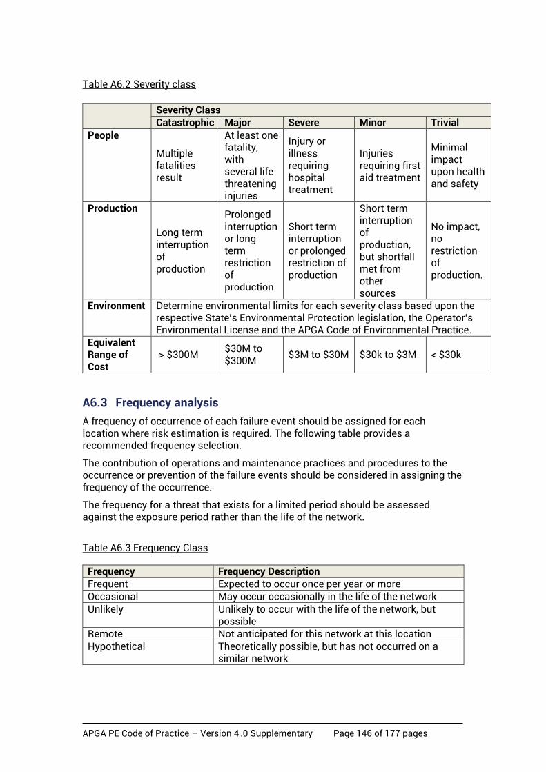
APGA PE Code of Practice – Version 4 .0 Supplementary Page 146 of 177 pages
Table A6.2 Severity class
Severity Class
Catastrophic Major Severe Minor Trivial People
Multiple fatalities result
At least one fatality, with several life threatening injuries
Injury or illness requiring hospital treatment
Injuries requiring first aid treatment
Minimal impact upon health and safety
Production
Long term interruption of production
Prolonged interruption or long term restriction of production
Short term interruption or prolonged restriction of production
Short term interruption of production, but shortfall met from other sources
No impact, no restriction of production.
Environment Determine environmental limits for each severity class based upon the respective State’s Environmental Protection legislation, the Operator’s Environmental License and the APGA Code of Environmental Practice.
Equivalent Range of Cost
> $300M $30M to $300M
$3M to $30M $30k to $3M < $30k
A6.3 Frequency analysis
A frequency of occurrence of each failure event should be assigned for each location where risk estimation is required. The following table provides a recommended frequency selection.
The contribution of operations and maintenance practices and procedures to the occurrence or prevention of the failure events should be considered in assigning the frequency of the occurrence.
The frequency for a threat that exists for a limited period should be assessed against the exposure period rather than the life of the network.
Table A6.3 Frequency Class
Frequency Frequency Description Frequent Expected to occur once per year or more Occasional May occur occasionally in the life of the network
Unlikely Unlikely to occur with the life of the network, but possible
Remote Not anticipated for this network at this location Hypothetical Theoretically possible, but has not occurred on a
similar network

APGA PE Code of Practice – Version 4 .0 Supplementary Page 147 of 177 pages
A6.4 Risk ranking
The results of the consequence and frequency analysis should determine the risk associated with the failure event.
Risks determined to be low or negligible or demonstrated to be ALARP are acceptable risks. Table A6.4 Risk Matrix
Catastrophic Major Severe Minor Trivial
Frequent
Extreme Extreme High Intermediate Low
Occasional
Extreme High Intermediate Low Low
Unlikely
High High Intermediate Low Negligible
Remote
High Intermediate Low Negligible Negligible
Hypothetical
Intermediate Low Negligible Negligible Negligible
A6.5 Risk mitigation
Action to reduce risk should be taken in accordance with Table A6.5 based upon the risk rank determined. The action(s) taken and its effect on safety management should be documented and approved. Where the risk rank cannot be reduced to ‘Low’ or ‘Negligible’, action should be taken to:
a) remove the threat, reduce the frequency or consequence of the threat to the extent practicable; or
b) demonstrate ALARP.
Table A6.5 Required Actions
Risk rank Required action Timing of action for
an operational network
Extreme Modify the threat, the frequency or the consequence so that the risk rank is reduced to ‘Intermediate’ or lower
Immediate
High Modify the threat, the frequency or the consequence so that the risk rank is reduced to ‘Intermediate’ or lower
Within a month
Intermediate
Repeat the threat identification and risk evaluation to verify and where possible quantify the risk estimation. Where the risk rank is confirmed as ‘Intermediate’ modify the threat, the frequency or the consequence so that the risk rank is reduced to ‘Low’ or ‘Negligible’.
Within 6 months
Low Determine the management plan for the threat to prevent occurrence and monitor changes that could affect the risk rank.
Negligible Review at the next review interval.
APGA PE Code of Practice – Version 4 .0 Supplementary Page 148 of 177 pages
A6.6 ALARP
A risk cannot be demonstrated as ALARP until consideration has been given to:
a) means of further reducing the risk; and
b) the reasons these further means have not been adopted.
ALARP is achieved when the cost of further risk reduction measures is grossly disproportionate to the benefit gained from the reduced risk that would result.
There is a need to show that a range of options were considered, and that those chosen actually reduce the risk to a level that is as low as reasonably practicable. Cost benefit analysis to determine the maximum justifiable spend is only one factor in demonstration of ALARP. Determining if the risk from a specific threat has been reduced to ALARP involves a comparison between the assessment of the risk to be avoided and the effectiveness and cost of the measure(s) involved in avoiding the risk. The cost ranges provided in Section A6.2 may be used as the basis of determining the cost of the risk. The measure of whether ALARP has been achieved is if the cost of reducing the risk is grossly disproportionate to the benefit gained.
The concept of ALARP contains an implicit assumption that there are alternative designs or measures that can reduce the risk but some of the alternatives may not be practicable. There is always one alternative: abandon the project or shutdown the network or that part of the network to which the threat is applied.
A7 Gas radiation contour
A7.1 General
The Code of Practice requires consideration of the consequence distance in terms of the radiation intensities of 4.7 kW/m2 and 12.6 kW/m2. This section provides guidance on the method of calculation of the radiation contour of gas networks.
NOTE: A thermal radiation level of 4.7 kW/m2 will cause injury, at least second-degree burns, after 30-seconds exposure. A thermal radiation level of 12.6 kW/m2 represents the threshold of fatality, for normally clothed people, resulting in third degree burns after 30-seconds exposure.
The radiation contour may be calculated based on the estimated release rate (MJ/s) and the calculations provided in API 521 ‘Pressure-relieving and Depressuring Systems’.
As the hole size increases relative to the pipe diameter the release rate and radiation distance will be controlled by the capacity of the network to deliver gas to the release point.
PE is not normally subject to rupture although full diameter leaks may occur as a result of a pipe joint failure.
The following radiation contour curves are informative based upon full diameter leaks and the leak expected to result from a 120 mm hole due to penetration by a 35 ton excavator (the maximum size machine normally used in CSG operations) at various pressures up to the limit of this Code of Practice.

APGA PE Code of Practice – Version 4 .0 Supplementary Page 149 of 177 pages
The calculation of the radiation contour should be completed at the maximum allowable operating pressure (MAOP) of the network.
Figure A7.1a - Radiation Contour Radius – Full Diameter
Figure A7.1b - Radiation Contour Radius – Penetration
APGA PE Code of Practice – Version 4 .0 Supplementary Page 150 of 177 pages
A8 CSG Water network leaks
A8.1 General
For CSG water network lines the impact upon the environment requires specific consideration of the following:
a) the water characteristic – pfw, saline water or treated water
Note: entrained gas should be considered.
b) the topography of the land
c) the proximity of surfaces of water – watercourses, rivers, dams or billabongs
d) the soil type in the vicinity of the network segment in question
e) the failure event hole size
f) the elevation profile of the network
g) the maximum spill volume
h) the proximity of environmentally significant locations or protected location
of flora and fauna.
The water release rate from the line may exceed the normal design flowrate or pump rate depending upon the change in elevation of the section.
The calculation of the water release rate should be completed at the maximum
allowable operating pressure (MAOP) of the network.
A8.2 Penetration hole size
An approximate hole size of 120 mm is suggested for a 35-tonne excavator. (This is the equivalent hole size for penetration of all general-purpose teeth on the standard bucket for this machine).

APGA PE Code of Practice – Version 4 .0 Supplementary Page 151 of 177 pages
• APPENDIX B – Pressure Testing (Normative)
Contents B1 Calculation for Pneumatic Pressure Decay Method B2 Stored Energy and Safe Distance Calculation – Pneumatic Tests B3 Stored Energy and Safe Distance Calculation – Hydraulic Tests B4 Pressure Rebound Test (Hydraulic) B5 Pressure Decay Test (Hydraulic) B6 Constant Pressure Test (Hydraulic) B7 Typical Test Forms

APGA PE Code of Practice – Version 4 .0 Supplementary Page 152 of 177 pages
B1 Calculation for pneumatic pressure decay method
A method of calculation for the allowable pressure loss in the pneumatic pressure decay test is:
D = the outside pipe diameter in a uniform test section, in mm L = the length of a uniform test section, in metres
t = the wall thickness of the pipe in a uniform test section, in mm Pa = absolute atmospheric pressure, in kilopascals, 101.3 kPa
P1 = test pressure, in kilopascals (normally 1.25 × MAOP) Loss = Acceptable loss rate per hour per cubic metres = l /hr/act m3 (See Section 8.6.6.2) T = test period, in hours, normally 24 hours
V = total volume under test pressure, in cubic metres = (L × π × (D – 2 × t)2 ) / (4 × 1000000) cubic metres
V1 = Starting volume – actual cubic metres
= V x (P1+Pa) / Pa Vloss = Acceptable loss – litres/hr = V1 × Loss
Vlosstest = Acceptable loss in test – m3/test = T × (Vloss / 1000)
Plosstest = Acceptable pressure loss in the test – kPa = (P1 + Pa) – [(P1 + Pa) × (V1 – Vlosstest) / V1] P2 = Acceptable pressure at end of test period – kPa = P1 – Plosstest

APGA PE Code of Practice – Version 4 .0 Supplementary Page 153 of 177 pages
B2 Stored energy and safe distance calculation: pneumatic tests
The following method is from AME PCC-2. The stored energy of the equipment or piping system should be calculated and converted to equivalent kilograms of TNT (Trinitrotoluene) using the following equations. A method of calculation of stored pneumatic energy is:
D = the outside pipe diameter in a uniform test section, in mm L = the length of a uniform test section, in metres
t = the wall thickness of the pipe in a uniform test section, in mm k = ratio of specific heat for the test fluid, 1.4 for air. Pa = absolute atmospheric pressure, in kPa, 101.3 kPa
Pat = absolute test pressure, in kPa TNT = equivalent kilograms of TNT (Trinitrotoluene)
V = total volume under test pressure, in litres = {L × π × (D – 2 × t)2 } / (4 × 1000) litres
To calculate the stored energy (SE) SE = [1/(k-1)] × Pat × V × [1 – (Pa/Pat)[(k-1)/k]] Joules
When using air or nitrogen as the test medium (k = 1.4), this equation becomes
SE = 2.5 × Pat × V × [1 – (Pa/Pat)0.286] Joules Equivalent kilograms of TNT (Trinitrotoluene)
TNT = SE/4266920 kg Safe distance calculation: pneumatic tests This safe distance calculation is based on the stored energy calculation detailed above and the safe distance calculation adapted from ASME PCC-2. This calculation details the minimum distance required for a pneumatic test. An Rscaled number of 20 is recommended for the distance from the pipeline to the limited boundary access (primary exclusion zone).
APGA PE Code of Practice – Version 4 .0 Supplementary Page 154 of 177 pages
A method of calculation of safe distance is:
R = safe distance, in meters Rscaled = safe distance scaled consequence factor from ASME PCC-2 Article
5.1, Mandatory Appendix III, Table III-1. Refer Table B3, Appendix B3. Rscaled = 20 (minimum)
For pneumatic testing, the minimum distance between all personnel and the equipment being tested shall be:
(a) R = 30 m for SE ≤ 135 500 000 J (b) R = 60m for 135 500 000 J < SE ≤ 271 000 000 J (c) R = Rscaled × (2TNT)1/3 = 20 × (2TNT)1/3 m for SE > 271 000 000 J
B3 Stored energy and safe distance calculation: hydraulic tests NOTES:
1. This method is based on the calculation in AS 2885.5 - 2012 and adapted for PE. For further information refer to this standard.
2. This equation assumes a maximum residual air content of 0.2%. The test shall be conducted by a competent operator by means of a controlled fill to ensure the maximum residual air content does not exceed the value assumed in the stored energy calculation. Verification of actual volume may be performed during the filling operation.
A method of calculation of stored energy is:
D = the outside pipe diameter in a uniform test section, in mm L = the length of a uniform test section, in metres p = the test pressure, in kilopascals SE = total stored energy, in Joules t = the wall thickness of the pipe in a uniform test section, in mm T = average temperature of test section, in oC Vo = the total initial volume of water in the test section, in litres = {L × π × (D – 2 × t)2 } / (4 × 1000) litres A = Compressibility of testing medium, in kPa-1 = (3.897×10⁻³ × T2 − 0.3133 × T + 50.65) × (1− p/411844) × 10−8 TNT = equivalent mass of TNT (Trinitrotoluene), in kilograms %air = 0.2% (assuming a maximum residual air content of 0.2%) Vair = Vo × %air = Vo × 0.002 volume of air in litres

APGA PE Code of Practice – Version 4 .0 Supplementary Page 155 of 177 pages
VH2O = Vo × (1 − %air) = Vo × (1 − 0.002) volume of water in litres ν = 0.4 = Poisson’s ratio
E = Young’s Modulus = 800,000 kPa NOTE: 800,000 kPa is used for the purpose of this calculation; typically 600,000 to 1,400,000 kPa for PE.
To calculate stored energy in a water-filled pipeline (assuming a negligible temperature change).
ΔV = VH2O × {(1 − ν2)/E × D/t + A} × p
where the stored energy (SEH2O) is the volume under the PV curve: SEH2O = stored energy of water, in Joules
= 0.5 × p × ΔV Joules
The method contained within AS/NZS 3788 and ASME PCC-2 to calculate stored energy in residual air may be applied:
SEair = 2.5 × (p + 101.3) × Vair × {1 – [101.3/(p + 101.3)] 0.286} Joules
Total stored energy: SE = SEair + SEH2O Joules
Equivalent kilograms of TNT (Trinitrotoluene) TNT = SE/4266920 kg
Safe distance calculation: hydraulic tests
This safe distance calculation is based on the stored energy calculation detailed above, known hydraulic energy release mechanism during pressure testing rupture events, and the safe distance calculation adapted from ASME PCC-2.
This calculation details the minimum distance required for a hydraulic test. A minimum Rscaled number of 20 is recommended for the distance from the pipeline to the limited boundary access (primary exclusion zone).
A method of calculation of safe distance is:
R = safe distance, in metres Rscaled = safe distance scaled consequence factor from ASME PCC-2, Article 5.1, Mandatory Appendix III, Table III-1 below. Rscaled = 20 (minimum) TNT = equivalent mass of Trinitrotoluene as calculated above, in kg

APGA PE Code of Practice – Version 4 .0 Supplementary Page 156 of 177 pages
Table B3 – Rscaled Consequence Factor – extract from ASME PCC-2
Rscaled m/kg1/3
Biological effect Structural failure
20 . . . Glass windows 12 Eardrum rupture Concrete block panels 6 Lung damage Brick walls 2 Fatal . . .
For hydraulic testing, the minimum distance between all personnel and the equipment being tested shall be the greater of:
(a) R = 5m (b) R = Rscaled × (2TNT)1/3 = 20 × (2TNT)1/3 m
NOTE: The risk of blast wave, present during pneumatic tests, is only applicable to the minimal residual air component during hydraulic tests which enables reduction in the safe distance used.
B4 Pressure rebound test (hydraulic)
B4.1 Application
This test has been validated for PE pressure pipelines. It may be used for other materials, given the appropriate data verifies suitability for use. Consideration should be given to systems where there are number of steel components such as risers and manifolds within the system and to the disposal of volumes of water during the test.
This test is applicable to PE pressure pipelines up to and including DN 315.
NOTE: This Test is based on BS EN 805, Appendix A.
B4.2 Pressure measurement rig
The test rig shall be a calibrated pressure transducer, data logger and check pressure gauge that has a dial of at least 100 mm diameter and a pressure range that places the CTP within the range 35 per cent to 70 per cent of the gauge’s full scale. The transducer and the check gauge shall read within 5 per cent of each other. If they do not agree within this tolerance, the equipment shall be re-calibrated or replaced.
B4.3 Procedure
The test procedure has the following three phases:
A preliminary phase in which is:
a) the pipeline is depressurised and allowed to relax after the strength test Section 8.4.1;
b) the pipeline is pressurised quickly to the test pressure and maintained at this pressure for a period of time without further water being added;
c) the pressure is allowed to decay by visco-elastic creep; and

APGA PE Code of Practice – Version 4 .0 Supplementary Page 157 of 177 pages
d) Provided the pressure drop does not exceed a specified maximum, the pressure test can proceed to the second phase.
A secondary phase in which the volume of air remaining in the pipeline is assessed against an allowable maximum.
The main test phase in which the pipeline is maintained at the test pressure for a period of time and decay due to visco-elastic creep commenced. The creep is interrupted by a rapid reduction of the pressure in the pipeline to a specified level. This rapid reduction in pressure results in contraction of the pipeline with an increase (rebound) in pressure.
If, during the rebound period, the pressure vs time record shows a fall in pressure, the pipeline fails the test.
B4.4 Preliminary phase
The procedure shall be as follows:
a) Reduce pressure to just above atmospheric at the highest point of the test length, and let stand for 60 minutes. Ensure no air enters the line
b) Raise the pressure smoothly to CTP2 in less than 10 min. Hold the pressure at CTP for 30 minutes by pumping continuously, or at short intervals as needed. Do not exceed CTP.
c) Inspect for leaks during the 30 min period, and then shut off the pressure.
d) Allow the pressure to decay for 60 min.
e) Measure the pressure remaining at 60 min (P60).
f) If P60 ≤ 70% of CTP the test has failed. The cause of the leak shall be located and rectified. Steps (a) to (e) shall be repeated. If P60 > 70% of CTP, proceed to the air volume assessment.
B4.5 Air volume assessment
The procedure shall be as follows:
a) Quickly (<5 min) reduce pressure by ΔP (10% to 15% of CTP).
b) Measure the water volume bled out (ΔV).
c) Calculate ΔVmax allowable as follows: ΔVmax allowable = 1.2xVx ΔP(1/EW + Di/ER) Where: 1.2 = air allowance
V = pipe volume, in litres ΔP = measured pressure drop, in kilopascals Di = pipe internal diameter, in metres ER = material modulus, in kilopascals (see Table B4.5a) EW = bulk modulus of water, in kilopascals (see Table B4.5b).
2 The acronym CTP “Calculated Test Pressure” is used instead of STP “Stipulated Test Pressure” as this can be confused with “Standard Temperature and Pressure”.

APGA PE Code of Practice – Version 4 .0 Supplementary Page 158 of 177 pages
d) If ΔV > ΔVmax allowable, the test has failed. The cause shall be located and rectified. The preliminary phase shall be repeated. If ΔV ≤ ΔVmax allowable, proceed to the main test phase.
NOTE: ΔV and ΔP should be measured as accurately as possible, especially where the test length volume is small.
Table B4.5a - Pipe E material modulus for PE100
Table B4.5b - Bulk modulus Ew – Water
BULK MODULUS Ew – WATER
Temperature ºC Bulk Modulus (kPa x 10³)
5
10
15
20
25
30
2080
2110
2140
2170
2210
2230
B4.6 Main test phase
Observe and record the pressure rise for 30 minutes.
In the event of failure, locate and repair the leak(s). If failure is marginal or doubtful, or if it is necessary to determine leakage rate, use a reference test. NOTE: Figure B4.6 gives an example of a full pressure test with the main test phase extended to 90 min.
PIPE E MATERIAL MODULUS FOR PE100
Temp
ºC
PE 100- E Modulus (kPa x 10³)
1h 2h 3h
5
10
15
20
25
30
990
900
820
750
690
640
930
850
780
710
650
610
900
820
750
680
630
600
NOTE: Table assumes a medium range density for PE100

APGA PE Code of Practice – Version 4 .0 Supplementary Page 159 of 177 pages
Figure B4.6 - Typical successful modified rebound test for a pipeline
B5 Pressure decay test (hydraulic)
B5.1 Application
This test has been validated for PE pressure pipelines. It may be used for other materials, given the appropriate data verifies suitability for use. Considerations should be given to systems where there are number of steel components such as risers and manifolds within the system.
NOTE: This method is based on Section 5 of A guide to testing of water supply pipelines and sewer rising mains, 1st Edition, June 1999, published by Water Research Committee (WRC
Plc),UK.
B5.2 Pressurising the pipeline
The procedure shall be as follows:
Apply the specified test pressure by pumping continuously at a constant rate.
The rate at which the pressure is increased to the calculated test pressure (CTP), and therefore the pump size, is important. The longer it takes to raise the pressure, the more time the pipeline has to expand (creep). Total test duration is related to the initial load time, leading to a long test duration, which may make other factors, e.g. temperature fluctuations, important. If the rate of pressurisation is too high, it becomes difficult to control the pressure and the pipeline could be overloaded.
NOTE: Air removal from the system could become a problem.
Volume added can be estimated from the number of full strokes of the piston or by direct measurement using a measurement recording device such as a flow meter.
Monitor and record the pressure rise and the time taken (loading time (tL)) to reach the CTP. The load time should not be less than five (5) minutes. For smaller systems
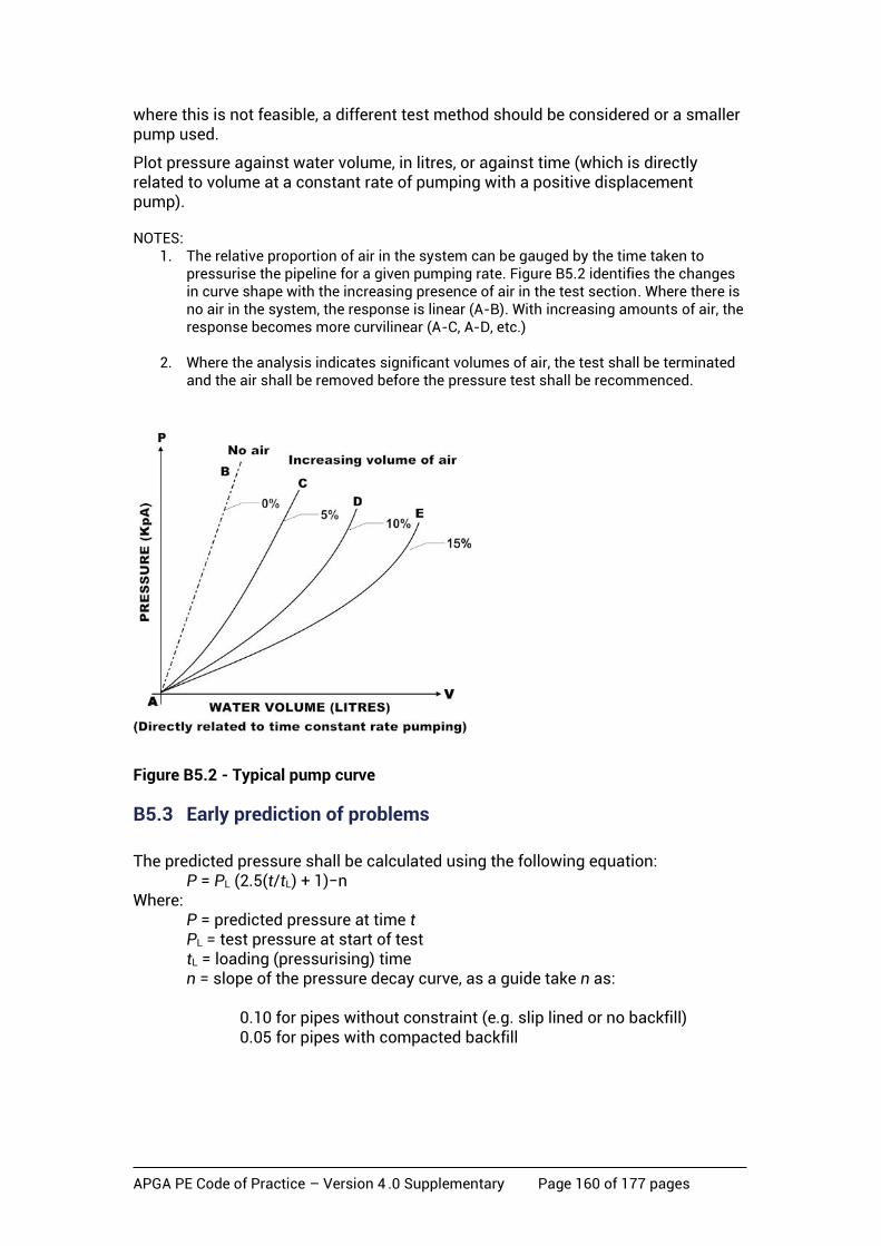
APGA PE Code of Practice – Version 4 .0 Supplementary Page 160 of 177 pages
where this is not feasible, a different test method should be considered or a smaller pump used.
Plot pressure against water volume, in litres, or against time (which is directly related to volume at a constant rate of pumping with a positive displacement pump). NOTES:
1. The relative proportion of air in the system can be gauged by the time taken to pressurise the pipeline for a given pumping rate. Figure B5.2 identifies the changes in curve shape with the increasing presence of air in the test section. Where there is no air in the system, the response is linear (A-B). With increasing amounts of air, the response becomes more curvilinear (A-C, A-D, etc.)
2. Where the analysis indicates significant volumes of air, the test shall be terminated
and the air shall be removed before the pressure test shall be recommenced.
Figure B5.2 - Typical pump curve
B5.3 Early prediction of problems
The predicted pressure shall be calculated using the following equation:
P = PL (2.5(t/tL) + 1)−n Where:
P = predicted pressure at time t PL = test pressure at start of test tL = loading (pressurising) time n = slope of the pressure decay curve, as a guide take n as:
0.10 for pipes without constraint (e.g. slip lined or no backfill) 0.05 for pipes with compacted backfill

APGA PE Code of Practice – Version 4 .0 Supplementary Page 161 of 177 pages
NOTES: 1. As the test can take some time to complete, it may be helpful to have an early
indication of problems such as leakage or air entrapment. 2. Since the logarithmic plot of pressure and time for an ideal PE pipeline system is
linear, comparing the actual pressure with the predicted pressure highlights problems.
B5.4 Three-point analysis procedure
The specified test pressure shall be applied and the high point air release valves and the pump feed valve shall be isolated by closing them. The pressure shall then be allowed to decay.
NOTE: The longer the time, between reaching the test pressure and the final reading, the more reliable the test results become. Taking more than three readings improves the reliability of the test results.
With reference to Figure B5.4, the three-point analysis test procedure shall be as follows:
a) At the moment of valve closure, time t = 0 and tL = loading time.
b) Take the first reading of pressure P1 at t1, where t1 =0 + tL
c) Take a second reading of pressure P2 at t2 (approximately 7tL).
d) Take a third reading of pressure P3 at a t3 (not less than 15tL).
Figure B5.4 - Typical pressure/ volume plot
APGA PE Code of Practice – Version 4 .0 Supplementary Page 162 of 177 pages
To allow for the creep behaviour of PE pipeline while being pressurised, the corrected values of t1, t2 and t3 shall be calculated by using:
t1c = t1 + 0.4tL
t2c = t2 + 0.4tL
t3c = t3 + 0.4tL
The slope of the pressure decay curve between t1 and t2 (slope n1) shall be calculated by using:
n1 = (log P1 – log P2) / (log t2c – log t1c) and between t2 and t3 (slope n2) by using:
n2 = (log P2 – log P3) / (log t3c – log t2c)
B5.5 Acceptance criteria
The test length shall be acceptable (no leakage) if n1 and n2 lie within the range 0.04 to 0.1 as follows:
i. 0.08 – 0.10 for unsupported pipes (e.g. slip-lined or no backfill).
ii. 0.05 – 0.08 for pipes in intermediate ground conditions.
iii. 0.04 – 0.05 for pipes in compacted backfill (loading time (tL)).
If the plotted line is not straight, it shall be interpreted as follows:
a) Was shallow, now within the above range. There may have been a small amount of air in the pipeline holding the pressure up, but it has now escaped or has little effect. The test length is acceptable.
b) Was steep, now within the above range. Just after the test section is isolated and before t1, there is often a small steep drop. Where the drop is very large, there may have been a pressure sensitive leak. The test length is acceptable.
c) Was within the above range, now shallow. The pipe may have expanded and reached an obstruction e.g. an outer pipe where it was slip-lined or surrounding backfill. The test length is acceptable.
d) Was within the above range, now steep. The test length is not acceptable. There is a leak. Carry out checks as for n>0.10
e) If the plotted line was not in the above range, the test length shall not be acceptable.
APGA PE Code of Practice – Version 4 .0 Supplementary Page 163 of 177 pages
B5.6 Troubleshooting and retesting
Where a test length is not acceptable, the fault shall be corrected and the pipeline retested. The minimum time between repeat tests shall be five (5) times the total test time.
NOTE: The following interpretations provide guidance:
• n < 0.04: there is probably air in the system.
• n > 0.10: the system is probably leaking.
• n > 0.15: there is almost certainly a leak.
B6 Constant pressure test (hydraulic)
B6.1 Application
The test method in this section is based on the constant pressure (water loss) method for visco-elastic pressure pipelines detailed in AS 2566.2.
For plastics pipes that are subjected to internal pressure, there will be a progressive drop in that pressure due to creep. Accordingly, it may be difficult to assess whether a pipeline is leaking or simply subject to creep. In order to overcome this difficulty, this method is based on the principle that if the pressure is held constant, there will be a linear relationship between hoop strain and logarithmic time.
Variables such as pipe stiffness and soil compaction are irrelevant, as the test result is based on actual performance during the test. Temperature may be considered constant, as with other test methods, unless special conditions exist.
B6.2 Pressurisation and procedure
The pipeline shall be tested as follows:
The recommended rate of filling shall be based on a flow velocity of 0.05 m/s, i.e. calculated from the following equation:
Qf ≤ 12.5 π D2
Where Qf = filling rate in litres per second
D = pipe diameter in metres
During the filling process, purge all air from the test section.
Raise pressure to the calculated test pressure (CTP), close of test section and allow to stabilise for at least 12 hours. During this period pressure will fall as a result of pipe expansion and creep.
Using water of the same temperature as that in the pipeline (±3°C) restore and maintain the CTP;
Measure and record water volume added at 2 hr, 3 hr, 4 hr, and 5 hr from start;
Conclude the constant pressure test five hours after completion of the 12-hour stabilisation period. For optimum test results, the following tolerances are recommended:
• water volume: ±10D litres, where D = pipe nominal diameter in metres;

APGA PE Code of Practice – Version 4 .0 Supplementary Page 164 of 177 pages
• time: ±1 min;
• pressure: ±1 kPa.
Calculate the water volume added between the second and third hour, ΔV(3h–2h) and the volume added between the fourth and fifth hour, ΔV(5h–4h).
Calculate Vall = 0.14.L.D.H (ref. AS/NZS 2566.2, Section 6.3.4)
Where Vall = volume makeup allowance, in litres/hour
L = test length, in kilometres
D = Pipe nominal diameter, in metres
H = average test head over pipeline length, in metres.
B6.3 Acceptance criterion
The test will be acceptable in accordance with AS/NZS 2566.2. Clause 6.3.4 as follows:
a) Test section has been pressurised to CTP and allowed to stabilise for a minimum of 12 hours.
b) Test section has been subjected to a 5-hour Constant Pressure Test.
c) There are no pipeline component failures.
d) There is no visible leakage.
e) ΔV(5h–4h) ≤ 0.55ΔV(3h–2h) + Vall.

APGA PE Code of Practice – Version 4 .0 Supplementary Page 165 of 177 pages
B7 Typical Test Forms
TEST NOTIFICATION FORM PROJECT TITLE: PROJECT NUMBER: CLIENT: CLIENT ID NUMBER: TEST PARK
DESCRIPTION:
TEST PACK NUMBER:
SECTION: FROM: TO: LOCATION: RELATED ITP: SYSTEM NUMBER: SYSTEM TYPE: P&ID NO: DRAWING NO: DATE SUBMITTED: TO THE ATTENTION OF: DATE OF PROPOSED
TEST:
TEST DURATION:
START TIME: FINISH TIME: SITE CONTACT: CONTACT TELEPHONE NO: EMERGENCY CONTACT: EMERGENCY TELEPHONE NO: TEST TYPE: *Hydraulic/Pneumatic TEST MEDIUM: MAXIMUM TEST
PRESSURE: KPA
EXCLUSION ZONE
*(Meters/Map No.):
ADDITIONAL COMMENTS:
CONTRACTOR CLIENT
Approved by: Approved by:
Name: Name:
Position: Position:
Signature: Signature:
Date: Date:
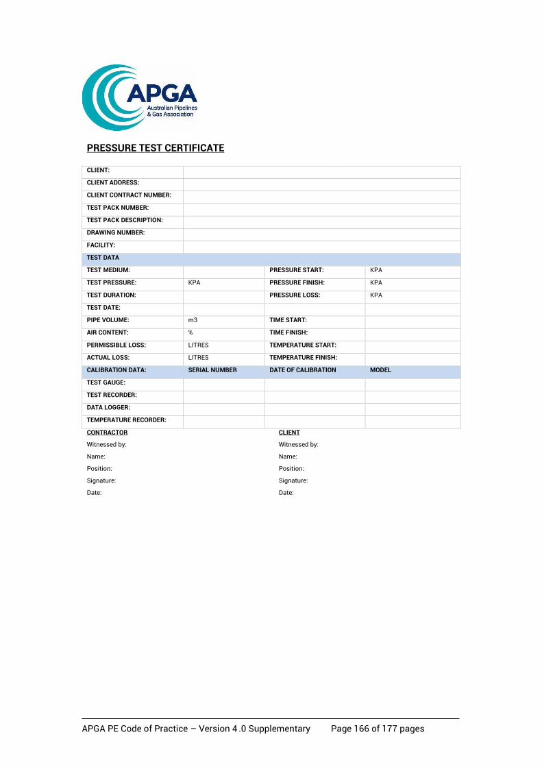
APGA PE Code of Practice – Version 4 .0 Supplementary Page 166 of 177 pages
PRESSURE TEST CERTIFICATE CLIENT: CLIENT ADDRESS: CLIENT CONTRACT NUMBER: TEST PACK NUMBER: TEST PACK DESCRIPTION: DRAWING NUMBER: FACILITY: TEST DATA TEST MEDIUM: PRESSURE START: KPA TEST PRESSURE: KPA PRESSURE FINISH: KPA
TEST DURATION: PRESSURE LOSS: KPA
TEST DATE:
PIPE VOLUME: m3 TIME START:
AIR CONTENT: % TIME FINISH:
PERMISSIBLE LOSS: LITRES TEMPERATURE START:
ACTUAL LOSS: LITRES TEMPERATURE FINISH:
CALIBRATION DATA: SERIAL NUMBER DATE OF CALIBRATION MODEL
TEST GAUGE:
TEST RECORDER:
DATA LOGGER:
TEMPERATURE RECORDER:
CONTRACTOR CLIENT
Witnessed by: Witnessed by:
Name: Name:
Position: Position:
Signature: Signature:
Date: Date:

APGA PE Code of Practice – Version 4 .0 Supplementary Page 167 of 177 pages
• APPENDIX C – Testing of Final Construction and Repair Tie-ins (Informative)
Final butt or electrofusion tie-ins or ‘golden welds’ connecting pipe sections that have already been pressure tested, shall be installed in accordance with the welding jointing requirements of Section 7.5. To ensure correcting welding parameters, where practicable, pipe should be constructed such that an overlap occurs at the tie-in point so that excessive pipe can be cut in order to provide a production weld on completion of the tie in (see Figure C1).
Figure C1 - Pipe overlap With reference to Figure C2, the production weld should be completed on site in the same field conditions, using the same procedure, equipment and welder that will be used for the final tie-in weld. The production weld should be completed prior to the final tie-in in order that this joint can undergo a destructive test.
Figure C2 - Production weld/joint Where it is not practicable to overlap pipes, where an insertion of pipe (or pup piece) is required as shown in Figure C3, two production welds should be conducted prior to the final tie in as shown in Figure C4.
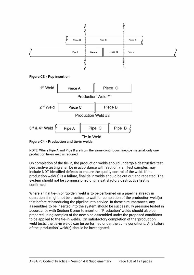
APGA PE Code of Practice – Version 4 .0 Supplementary Page 168 of 177 pages
Figure C3 - Pup insertion
Figure C4 - Production and tie-in welds
NOTE: Where Pipe A and Pipe B are from the same continuous linepipe material, only one production tie-in weld is required.
On completion of the tie-in, the production welds should undergo a destructive test. Destructive testing shall be in accordance with Section 7.9. Test samples may include NDT identified defects to ensure the quality control of the weld. If the production weld(s) is a failure, final tie in welds should be cut out and repeated. The system should not be commissioned until a satisfactory destructive test is confirmed. Where a final tie-in or ‘golden’ weld is to be performed on a pipeline already in operation, it might not be practical to wait for completion of the production weld(s) test before reintroducing the pipeline into service. In these circumstances, any assemblies to be inserted into the system should be successfully pressure tested in accordance with Section 8 prior to insertion. ‘Production’ welds should also be prepared using samples of the new pipe assembled under the proposed conditions to be applied to the tie-in welds. On satisfactory completion of the ‘production’ weld tests, the tie-in welds can be performed under the same conditions. Any failure of the ‘production’ weld(s) should be investigated.
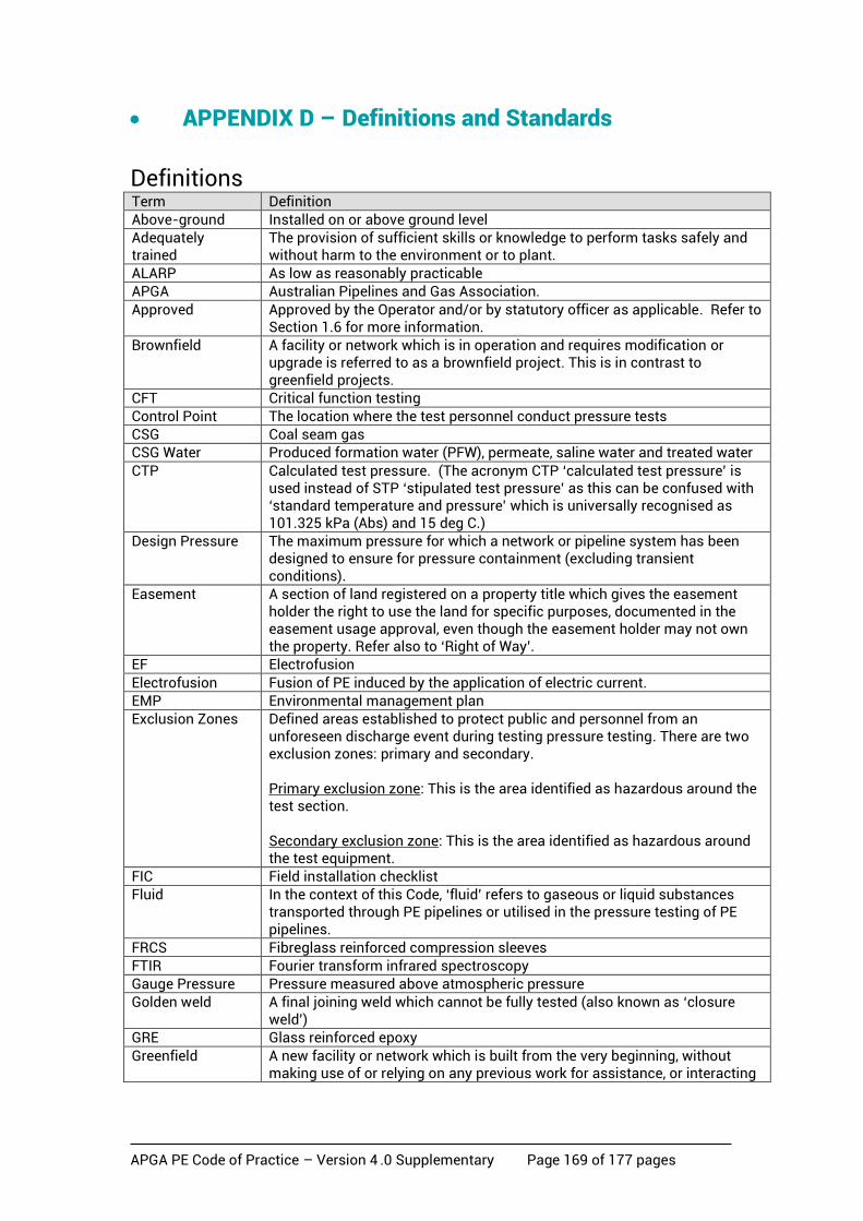
APGA PE Code of Practice – Version 4 .0 Supplementary Page 169 of 177 pages
• APPENDIX D – Definitions and Standards
Definitions Term Definition
Above-ground Installed on or above ground level
Adequately trained
The provision of sufficient skills or knowledge to perform tasks safely and without harm to the environment or to plant.
ALARP As low as reasonably practicable
APGA Australian Pipelines and Gas Association.
Approved Approved by the Operator and/or by statutory officer as applicable. Refer to Section 1.6 for more information.
Brownfield A facility or network which is in operation and requires modification or upgrade is referred to as a brownfield project. This is in contrast to greenfield projects.
CFT Critical function testing
Control Point The location where the test personnel conduct pressure tests
CSG Coal seam gas
CSG Water Produced formation water (PFW), permeate, saline water and treated water
CTP Calculated test pressure. (The acronym CTP ‘calculated test pressure’ is used instead of STP ‘stipulated test pressure’ as this can be confused with ‘standard temperature and pressure’ which is universally recognised as 101.325 kPa (Abs) and 15 deg C.)
Design Pressure The maximum pressure for which a network or pipeline system has been designed to ensure for pressure containment (excluding transient conditions).
Easement A section of land registered on a property title which gives the easement holder the right to use the land for specific purposes, documented in the easement usage approval, even though the easement holder may not own the property. Refer also to ‘Right of Way’.
EF Electrofusion
Electrofusion Fusion of PE induced by the application of electric current.
EMP Environmental management plan
Exclusion Zones Defined areas established to protect public and personnel from an unforeseen discharge event during testing pressure testing. There are two exclusion zones: primary and secondary. Primary exclusion zone: This is the area identified as hazardous around the test section. Secondary exclusion zone: This is the area identified as hazardous around the test equipment.
FIC Field installation checklist
Fluid In the context of this Code, ‘fluid’ refers to gaseous or liquid substances transported through PE pipelines or utilised in the pressure testing of PE pipelines.
FRCS Fibreglass reinforced compression sleeves
FTIR Fourier transform infrared spectroscopy
Gauge Pressure Pressure measured above atmospheric pressure
Golden weld A final joining weld which cannot be fully tested (also known as ‘closure weld’)
GRE Glass reinforced epoxy
Greenfield A new facility or network which is built from the very beginning, without making use of or relying on any previous work for assistance, or interacting

APGA PE Code of Practice – Version 4 .0 Supplementary Page 170 of 177 pages
with previously constructed facilities or networks is called a greenfield project. This is in contrast to a brownfield project.
HAZOP Hazard and operability study
Hydraulic Testing Testing using a liquid medium, almost always water. NOTE: This term replaces the earlier term ‘hydrostatic testing’ which, in some quarters, is now used to define both liquid and gaseous testing processes.
HDPE High density polyethylene. NOTE: While PE materials are commonly referred to as high density (HDPE), medium density (MDPE), low density (LDPE) or linear low density (LLDPE) these descriptors are not appropriate for the PE pipe compounds used for the CSG industry. There is no universally accepted delineation between MDPE and HDPE and density alone does not adequately describe the material. The term PE100 should always be applied to the PE pipes used for CSG as it ensures all of the appropriate performance requirements have to be met rather than simply a density range. Refer to the appropriate Companion Paper for further information.
HPU Hydraulic power unit
HPV High point vent
IBC Inside bolt centre
IMP Integrity management plan
ITP Inspection and test plan
JSA Job safety analysis; also commonly called job hazard analysis (JHA), and job hazard and environmental analysis (JHEA).
LoF Lack of fusion
Leak Test The leak test determines if there are any small leaks in the test system. The leak test shall be undertaken after a successful completion of a strength test.
Limited access boundary
An area which extends beyond the exclusion zone, and includes the control point and pressurising equipment.
LDPE Low density polyethylene. Refer to HDPE above and the appropriate Companion Paper for further information regarding the use of this term.
LLDPE Linear low-density polyethylene. Refer to HDPE above and the appropriate Companion Paper for further information regarding the use of this term.
LPD Low point drain
Major highways High capacity roads managed by state and territory government agencies.
MAOP Maximum allowable operating pressure: the maximum pressure at which a pipeline system may be operated in accordance with the design criteria and provisions set out in this code, Section 4.3.5. MAOP should not be confused with the PN rating of the pipeline.
MDPE Medium density polyethylene. Refer to HDPE above and the appropriate Companion Paper for further information regarding the use of this term.
MOP Maximum operating pressure – an interim adjustment representing the highest pressure a piping system may be subjected to during an interim operating period.
MRS Minimum required strength for the material in MPa at 20°C.
NDT Non-destructive testing
NMS Network management system
OH&S Any reference to workplace health and safety (WHS) should be taken to mean OH&S in Victoria and WA.
OHS&E Any reference to workplace health and safety and the environment (WHS&E) should be taken to mean OHS&E in Victoria and WA.
OIT Oxidation induction time
Operator The term refers to the entity that the regulatory authority holds accountable for the network.
P&ID Piping and instrumentation diagram

APGA PE Code of Practice – Version 4 .0 Supplementary Page 171 of 177 pages
PE Polyethylene
PFD Process flow diagram
PFW Produced formation water
PIPA Plastics Industry Pipe Association of Australia Ltd
PN Pressure nominal - nominal working pressure at 20 degrees C designated in bar. Refer AS/NZS 4130.
Pneumatic testing Testing using a gaseous medium, almost always air.
Preliminary test A test that is undertaken on a section of pipeline that will be subsequently exposed to a further strength test pressure when included in the main pipeline test section.
Pre-test A pressure test of a pipeline section or component that is undertaken separately from the pipeline and is not re-tested after installation. (eg. pipeline with a closure weld.)
Pressure test A pressure test consists of a strength test followed by a leak test
Production Test Destructive testing of a production weld.
Production weld Weld undertaken external to the pipeline installation, using the same material as the associated pipeline tie-in materials, for destructive testing purposes.
QA/QC Quality assurance and quality control
Right of way (ROW)
Pipeline route and work area, along the pipeline centreline, approved for construction, operation or maintenance purposes (usually temporary). Refer also to ‘easement’.
Strength test The strength (or proof) test is a means by which the integrity of a test section is assessed, this is carried out by filling with a fluid, sealing and subjecting to a calculated test pressure. The strength test is used to validate integrity and to detect any construction or mechanical defects and also defective materials.
PSV Pressure safety valve
QA Quality assurance
QC Quality control
RO Reverse osmosis
RTO Registered training organisation
Safety management study
A process that identifies threats to the pipeline system and applies controls to them, and (if necessary) undertakes assessment and treatment of any risks to ensure that residual risk is reduced to an acceptable level.
SCG Slow crack growth
SDR Standard dimension ratio
Shall A mandatory requirement.
Should A recommended action or guideline.
STP Stipulated test pressure or Standard temperature and pressure; refer to the acronym CTP ‘calculated test pressure’ for more information.
TDS Total dissolved salts
Test Section The pipeline or portion of pipeline being subjected to a pressure test.
Test System The pipeline system being subject to a pressure test.
Threat Any activity or condition that can adversely affect the pipeline if not adequately controlled.
UV Ultraviolet
WHS Workplace health and safety. Any reference to WHS should be taken to mean OH&S in Victoria and WA.
WHS&E Workplace health and safety and the environment. Any reference to WHS&E should be taken to mean OHS&E in Victoria and WA.

APGA PE Code of Practice – Version 4 .0 Supplementary Page 172 of 177 pages
Referenced Standards and Documents Standard/Document Title AGA-XK0775 Purging Principles and Practice
ANSI/ASTM B16.5 Pipe flanges and flanged fittings
API 521 Pressure-relieving and Depressuring Systems
AS 1319 Safety signs for the occupational environment
AS/NZS 1020 The control of undesirable static electricity
AS 1100.401 Technical drawing - Engineering survey and engineering survey design drawing
AS1463 Polyethylene pipe extrusion compounds
AS/NZS 2033 Installation of polyethylene pipe systems
AS 2129 Flanges for pipes, valves and fittings
AS2187.2 Explosives – storage and use – use of explosives
AS 2566.2 Buried flexible pipelines - Installation
AS 2885.1 Pipelines - Gas and liquid petroleum - Design and construction
AS 4041 Pressure piping
AS 4087 Metallic flanges for waterworks purposes
AS/NZS 4129 Fittings for polyethylene (PE) pipes for pressure applications
AS/NZS 4130 Polyethylene (PE) pipes for pressure applications
AS/NZS 4131 Polyethylene (PE) compounds for pressure pipes and fittings
AS/NZS 4158 Thermal-bonded polymeric coatings on valves and fittings for water industry purposes
AS/NZS 4331.1 Metallic flanges - Steel flanges
AS 4343 Pressure equipment – hazard levels
AS/NZS 4645.1 Gas distribution networks - Network management
AS/NZS 4645.3 Gas distribution networks - Plastics pipe systems
AS/NZS/ISO 31000 Risk management - Principles and guidelines
AS/NZS 60079 Electrical apparatus for explosive gas atmospheres
ASME B31.3 Process piping
ASME PCC-2 Repair of Pressure Equipment and Piping
ASTM D1598 Standard Test Method for Time-to-Failure of Plastic Pipe Under Constant Internal Pressure
ASTM F905 Standard Practice for Qualification of Polyethylene Saddle-Fused Joints
ASTM F1041 Standard guide for squeeze-off of Polyolefin Gas Pressure Pipe and Tubing
ASTM F1055 Standard Specification for Electrofusion Type Polyethylene Fittings for Outside Diameter Controlled Polyethylene and Crosslinked Polyethylene (PEX) Pipe and Tubing.
ASTM F1563 Standard Specification for Tools to Squeeze-Off Polyethylene (PE) Gas Pipe or Tubing
ASTM F1598 Standard Test Method for Determining the Effects of Chemical/Solvent Exposure to a Membrane Switch/Graphic Overlay (Spot Test Method)
ASTM F1734 Standard Practice for Qualification of a Combination of Squeeze Tool, Pipe, and Squeeze-Off Procedures to Avoid Long-Term Damage in Polyethylene (PE) Gas Pipe
ASTM F1962 Standard Guide for Use of Maxi-Horizontal Directional Drilling for Placement of Polyethylene Pipe or Conduit Under Obstacles, Including River Crossings
ASTM F2620 Standard Practice for Heat Fusion Joining of Polyethylene Pipe and Fittings
ASTT CPJP8029-GUI-C-001
Guidelines for Horizontal Directional Drilling, Pipe Bursting, Microtunnelling and Pipe Jacking
BS EN 805 Water supply. Requirements for systems and components outside buildings

APGA PE Code of Practice – Version 4 .0 Supplementary Page 173 of 177 pages
Standard/Document Title BS EN 1555-3 Plastics piping systems for water supply, and for drainage and sewerage
under pressure. Polyethylene (PE). Fittings.
BS EN 12201-4 Plastics piping systems for water supply, and for drainage and sewerage under pressure. Polyethylene (PE). Valves.
BS EN 13185:2001 Non-destructive testing- Leak testing- Tracer gas method
Evisive Paper HDPE Butt Fusion Weld Inspection and Imaging Using Evisive ScanTM Technology
Evisive Paper HDPE Pipe Electro-Fusion Coupling Inspection and Imaging Using Evisive ScanTM Technology
GIS/E4:2006 Inflatable, self-centring bag stoppers for use on distribution pipes of a nominal size up to and including 300 mm (12 in)
ICONE17-75742 Microwave based NDE inspection of HDPE pipe welds.
ISO/AS/NZS 9001 Quality management systems - Requirements
ISO/IEC 31010. Risk management - Risk assessment techniques
ISO 4437 Plastics piping systems for the supply of gaseous fuels - Polyethylene (PE).
ISO 7005.1 See AS/NZS 4331.1
ISO 11413 Plastics pipes and fittings - Preparation of test piece assemblies between a polyethylene (PE) pipe and an electrofusion fitting
ISO 11414 Plastics pipes and fittings. Preparation of polyethylene (PE) pipe/pipe or pipe/fitting test piece assemblies by butt fusion
ISO 13953 Polyethylene (PE) pipes and fittings - Determination of the tensile strength and failure mode of test pieces from a butt-fused joint
ISO 13954 Plastics pipes and fittings - Peel decohesion test for polyethylene (PE) electrofusion assemblies of nominal outside diameter greater than or equal to 90 mm
ISO 13955 Plastics pipes and fittings - Crushing decohesion test for polyethylene (PE) electrofusion assemblies
ISO 13956 Plastics pipes and fittings - Decohesion test of polyethylene (PE) saddle fusion joints - Evaluation of ductility of fusion joint interface by tear test
ISO 13957 Plastics pipes and fittings -- Polyethylene (PE) tapping tees -- Test method for impact resistance
ISO 14236 Plastics pipes and fittings - Mechanical-joint compression fittings for use with polyethylene pressure pipes in water supply systems
ISO 21307 Plastics pipes and fittings - Butt fusion jointing procedures for polyethylene (PE) pipes and fittings
ISO 21751 Plastics pipes and fittings - Decohesion test of electrofusion assemblies - Strip-bend test
PIPA TN016 Non Destructive Examination of PE welds – Emerging Techniques
PIPA TP005 Flexible Pipe Design
POP 001 PIPA Guideline: Electrofusion Jointing of PE Pipe and Fittings for Pressure Applications
POP 010A PIPA Guideline: Polyethylene pressure pipes design for dynamic stresses
POP 003 PIPA Guideline: Butt fusion jointing of PE pipes and fittings - recommended parameters
POP 004 PIPA Guideline: Polyethylene pipe compounds
POP 005 PIPA Guideline: Packaging, handling and storage of polyethylene pipes and fittings
POP 006 PIPA Guideline: Derating requirements for fittings
POP 007 PIPA Guideline: Metal backing flanges for use with PE pipe flange adaptors
POP 202 PIPA Guideline: PVC and PE pressure pipe installation on curved alignments
PIPA TN016 PIPA Guideline: Non Destructive Examination of PE welds – Emerging Techniques.
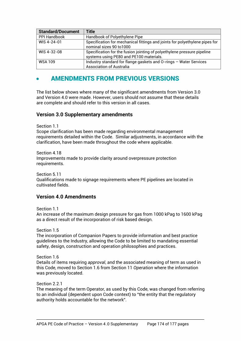
APGA PE Code of Practice – Version 4 .0 Supplementary Page 174 of 177 pages
Standard/Document Title PPI Handbook Handbook of Polyethylene Pipe
WIS 4-24-01 Specification for mechanical fittings and joints for polyethylene pipes for nominal sizes 90 to1000
WIS 4-32-08 Specification for the fusion jointing of polyethylene pressure pipeline systems using PE80 and PE100 materials.
WSA 109 Industry standard for flange gaskets and O-rings – Water Services Association of Australia
• AMENDMENTS FROM PREVIOUS VERSIONS The list below shows where many of the significant amendments from Version 3.0 and Version 4.0 were made. However, users should not assume that these details are complete and should refer to this version in all cases.
Version 3.0 Supplementary amendments Section 1.1 Scope clarification has been made regarding environmental management requirements detailed within the Code. Similar adjustments, in accordance with the clarification, have been made throughout the code where applicable. Section 4.18 Improvements made to provide clarity around overpressure protection requirements. Section 5.11 Qualifications made to signage requirements where PE pipelines are located in cultivated fields.
Version 4.0 Amendments Section 1.1 An increase of the maximum design pressure for gas from 1000 kPag to 1600 kPag as a direct result of the incorporation of risk based design. Section 1.5 The incorporation of Companion Papers to provide information and best practice guidelines to the Industry, allowing the Code to be limited to mandating essential safety, design, construction and operation philosophies and practices. Section 1.6 Details of items requiring approval, and the associated meaning of term as used in this Code, moved to Section 1.6 from Section 11 Operation where the information was previously located. Section 2.2.1 The meaning of the term Operator, as used by this Code, was changed from referring to an individual (dependent upon Code context) to “the entity that the regulatory authority holds accountable for the network”.
APGA PE Code of Practice – Version 4 .0 Supplementary Page 175 of 177 pages
Section 3.3.2.2 Added requirements for enabling an increase in pressure rating for fittings. Section 5.11.1.3 Updated to recognise detectable marker products in lieu of tracer wire.
Section 3.4.2 Added requirements for enabling an increase in pressure rating for valves. Section 4 Incorporation of risk based design in lieu of a fixed ‘risk’ design factor based upon the use of physical and procedural measures for risk mitigation in accordance with the location or sub-location class. Inclusion of the limited application of ‘composites’ in accordance with this Code; Section 4.16 Clarification of the scope applicability of ASME B31.3 and AS4041. Section 4.3 Introduction of the pressure test factor and removal of the risk factor. Section 4.5 Introduction of the risk control and mitigation details into the body of the Code. Section 4.8.2 Change to the location class to incorporate ‘High Use’ and ‘Sensitive’ sub-location classes. Section 4.13.1 Additional requirements added for the use of above-ground pipe subject to internal pressures greater than 80 kPag. Section 4.25 Requirements added for the use of alternative materials for sections of CSG water pipelines where the pressure at the lowest point exceeds 2500 kPag due to elevation head differences. Section 5 This Section covering Construction has been consolidated and re-written in parts to improve ease of usability. Much of the descriptive details of construction methods, found in the previous version of this Code, has been removed. Section 8.2 The information previously provided, regarding methods of reducing the amounts of pneumatic stored energy in the pipeline test section, has been removed. Section 8.4 Incorporation of risk based design in lieu of a fixed ‘risk’ design factor based upon the use of physical and procedural measures for risk mitigation in accordance with the location or sub-location class. Changes to pressure testing requirements updated to incorporate the pressure test factor introduced in this version of the
APGA PE Code of Practice – Version 4 .0 Supplementary Page 176 of 177 pages
Code. Details were also added for component testing and pre-testing as well as hot tapping and emergency response pressure testing for components. Section 9.4 Additional details provided to clarify the minimum information that should be recorded as part of abandonment records. Section 11 Previous details, around meaning and use of approvals in this Code, moved to Section 1.6. Section 11.5.1 Adjustments made clarifying the structural integrity issues that are required to be covered in the integrity management plan. Section 11.5.2 Further flow-stopping options now detailed in the body of this Code. Much of the information was provided in an Appendix of the previous version of this Code. Details previously provided - discussing clamps, sleeves and pipe reinforcement devices - have been removed. Section 11.9.5 Additional requirements have been added for the use of reinforcement sleeves and pressure containment sleeves. Appendices The following Appendices have been removed which were previously contained in Version 3.0 of the Code (as well as contained in Version 3.0 Supplementary):
• System Design Considerations; • Assessment of PE Welds;
• PE Materials Selection and Quality • Maintenance, Modifications and Emergency Response; • Sidewall Fusion Welding;
Some content removed from previous versions of this Code may be found in Companion Papers. Refer to the appropriate Companion Papers for further information.
Version 4.0 Supplementary amendments Section 1.3 New definition of objective of the Code. Section Error! Reference source not found. New method of service identification provided. Section 4.5.2 Updated Table 4.5.2 to provide a summary of interference controls. Section 4.8.2.2 a) and b)
APGA PE Code of Practice – Version 4 .0 Supplementary Page 177 of 177 pages
Clarification in sub location High Use and Sensitive area definitions. Section 4.13.1 Revision of use of above ground pipe use. Section 4.18 Definition of excursion times for pressure testing. Section 5.5.3 Removal of reference to suitability of striped pipes for above ground use and consolidation into Section 4.13.1. Section 5.11.3 Clarification note added for location of signs. Section 8.4.1.3 Revised definition of test temperature compensation. Section 11.9.5.2 b) Re-definition of compression sleeve. Appendix B2 Correction to minimum distance formula. Appendix D Inclusion of CSG Water definition and global use of term in Code.