code of practice for high friction surfacing · rsta code of practice for high friction surfacing...
TRANSCRIPT

RSTA Code of Practice for High Friction Surfacing
June 2011 1
Hand Applied Systems Machine Applied Systems
CODE OF PRACTICE FOR HIGH FRICTION SURFACING

RSTA Code of Practice for High Friction Surfacing
June 2011 2
Foreword
This first edition of the Code of Practice has been produced by the Road Surface Treatments Association (RSTA) High Friction Surfacing Committee to embrace industry best practice and to reference current specification guidance contained within the BBA HAPAS Scheme.
This document has been peer reviewed by ADEPT Soils, Materials, Design and Specifications Committee.
The information contained herein is intended to represent industry best practice. No liability is accepted by RSTA or ADEPT for any damages caused to property or personal injury resulting from using the guidance contained within this document.
RSTA is the Road Surface Treatments Association www.rsta-uk.org
ADEPT is the Association of Directors of Environment, Economy, Planning and Transport www.adeptnet.org.UK

RSTA Code of Practice for High Friction Surfacing
June 2011 3
Contents Page
Introduction 4
Suitable Sites for HFS 5
Types of High Friction Surfacing 5
Specification for High Friction Surfacing 6
Information to be Provided by the Client 7
Planning and Coordination 8
Health, Safety and Environment 8
Planning the Execution of The Work 9
Traffic Management 10
Surface Preparation 12
Constituents 14
Detailed Requirements For Each System 16
Performance Criteria 24
Quality Assurance 24
Training 25
Road Surface Treatments Association 26
Appendix A - Checklists 27
Appendix B - Glossary 29

RSTA Code of Practice for High Friction Surfacing
June 2011 4
1 Introduction
This Code of Practice has been written by the Road Surface Treatments Association (HFS Sector) and ADEPT to assist procurers and installers to obtain a high quality durable surface treatment.
It represents best practice for the selection and application of High Friction Surfacing Systems to maximise their performance and durability.
High Friction Surfacing is essential in many locations on the network to keep the road surface adequately safe for road users.
To obtain the best results it is necessary to give careful consideration to a wide range of details and to plan and design the work carefully and to use only BBA HAPAS Approved installers. BBA HAPAS categorises systems as Type-1, 2 and 3 systems, where Type-1 has attained the highest performance level. All comply with Clause 924 of the Specification for Highways Works, part of the Manual of Contract Documents for Highway Works.
The type of application in which the materials are applied and the prevailing ambient conditions at the time of installation are also important to ensure long term durability of the product.
The purpose of this Code is to identify the important aspects of the process, and to refer to other documents relating to good applications of high friction surfacing and so give practical guidance on achieving high quality.
This document is to be reviewed annually jointly by RSTA and ADEPT.
The Road Safety Marking Association (RSMA) endorses this document and encourages their members to support the use of the guidance contained herein.
RSTA Code of Practice for High Friction Surfacing
June 2011 5
2 Suitable sites for HFS
Each Local Authority should have its own Skid Resistance Policy that defines the way that the Investigatory Level is determined for a site.
To the highway engineer, high friction surfacing offers a surface application that provides a high level of skid resistance and so enhances safety and reduces accidents for high risk sites. High risk sites are generally defined as those requiring an Investigatory Level (IL) for friction (measured by SCRIM). These include:
approaches to major junctions
approaches to pedestrian crossings when pedestrians or other vulnerable road users may misjudge the speed of the traffic, for example near schools or where children cross, near public houses or where the approach speed is high
sites with gradients steeper than 10% if other hazards are present
bends with a radius of tighter than 500m on single carriageways, if there are risk factors present or a particular potential for loss of control such as an adverse camber or the geometry of the band is potentially hazardous for the traffic speed
Guidance on the selection of sites requiring HFS is also provided in ADEPT (CSS) Guidance - Use of High Friction Surfaces available on the CSS website http://www.adeptnet.org.uk/research/publications .
The site categories described in general above, together with the traffic levels at which HFS becomes necessary are detailed in the Design Manual for Roads & Bridges (DMRB): Volume 7 HD 36/06 available from www.dft.gov.uk/ha/standards/dmrb/.
A useful way of comparing the effectiveness of a High Friction Surfacing is through correlation between accidents black spots prior to high friction surfacing systems being applied and the results after the application of the systems.
Between 1991 and 2001 MOLASSES (MOnitoring Local Authority Safety SchemES) monitored a total of 2,309 Road Safety Schemes in the UK and calculated the Average Annual Accident Saved per year, by deducting the average number of accidents per year, after implementing each scheme from the average number of accidents prior implementation.
High Friction Surfacing achieved an accident reduction rate of 35.1% based on a site balance of 10% rural and 90% urban roads.
3 Types of High Friction Surfacing
There are two main categories of HFS – Cold Applied and Hot Applied.
Cold Applied
These systems comprise a resin binder which also acts as an adhesive for the aggregate, typically graded 1-3mm. The aggregate is very hard with a low Aggregate Abrasion Value (AAV) and with a high Polished Stone Value (PSV) that provides the necessary friction with the tyre.
Cold applied resins include epoxy, polyurethane and Methyl Methacrylate [MMA].
RSTA Code of Practice for High Friction Surfacing
June 2011 6
Cold applied resins are installed as continuous film of adhesive. They are either:
Blended and sprayed by machine onto which the aggregate is broadcast.
Blended mechanically and then manually applied by squeegee onto which the aggregate is broadcast.
In both cases, after the resin has cured, excess aggregate is removed by sweeping.
Further details are provided in Section 12 below.
Hot Applied
In hot applied materials the pre mixed resin and aggregate is heated in a truck mounted boiler at high temperature ensuring the material is mixed and workable. The hot thermoplastic material is screeded out in strips to cover the whole surface.
Further details are provided in Section 12 below.
4 Specification for High Friction Surfacing
High Friction Surfacing must comply with Specification for Highway Works (SHW) Clause 924 which requires such systems to be BBA HAPAS certificated. Successful certification under the BBA HAPAS scheme involves meeting demanding performance criteria which are given in each system’s certificate and meeting stringent Quality Assurance and Quality Control requirements on an ongoing basis.
The three key paragraphs are repeated as follows:
1 High friction surfacing systems shall have current British Board of Agrément HAPAS Roads and Bridges Certificates.
2 A high friction surfacing system with a current British Board of Agrément HAPAS Roads and Bridges Certificate shall only be installed by a Contractor approved by the BBA and the Certificate Holder as an Approved Installer for that system.
3 The installation and quality control procedures shall be in accordance with the British Board of Agrément Roads and Bridges Certificate for each system and the current method statement agreed by the BBA. The results of all quality control checks carried out on site by the Contractor and quality assurance information compiled in accordance with the requirements of the Certificate, including results from BBA surveillance visits, shall be made available to the Overseeing Organisation on request.
Clause 924 is an End Performance Specification. This transfers the responsibility for the design of the high friction system to the selected installer who is responsible for the execution of the surface treatment and generally guarantees the treatment for a specified period of time. Clause 924 provides a limited guarantee of a minimum of 2 years, subject to the following rider:
This guarantee shall exclude defects arising from damage caused by settlement, subsidence or failure of the carriageway on which the surfacing has been applied, but shall cover failure to meet the minimum requirements set out in Table 4 of the BBA HAPAS
RSTA Code of Practice for High Friction Surfacing
June 2011 7
‘Guidelines Document for the Assessment and Certification of High Friction Surfaces for Highways’.
If the client specifies that the high friction surfacing is installed in full compliance with this Code of Practice then the installer should be able to provide a 5 year guarantee for the appropriate class of system.
Please refer to Section13 below that highlights the Performance Criteria that is expected as part of the 5 year guarantee.
There are three classes of HFS; Type 1, Type 2 and Type 3 depending upon the volume of commercial vehicles using the lane and the degree of braking and turning the site is subjected to. Details are contained in the Guidelines Document for the Assessment and Certification of High Friction Surfacing obtainable from www.bbacerts.co.uk .
Designers have discretion within the site category with guidance being given in the Local Authority Skid Resistance Policy Document and for Highways Agency IAN 98/07. Refer to the BBA Guidelines document for the assessment and Certification of High Friction Surfacing for Highways – Table 2 Area of application by type classification.
This guidance and the guarantee of durability that it provides, only applies to systems manufactured and installed in accordance with Clause 924. The BBA website provides a full list of approved systems and installers for each product should the client wish to verify any information.
Further information on the requirement of the BBA HAPAS Scheme is given in the Section 13 Performance Criteria.
5 Information to be provided by the Client
The contract documents should state
a) The product and its installation shall comply with SHW Clause 924 i.e. be manufactured and installed by companies with a BBA HAPAS Installers Certificate for the relevant system
b) The Type of system ( see Para 4)
c) A clear site drawing indicating the area to be treated
d) The length and average width of each section, possibly by means of a schedule
e) The existing surface type on which the system is to be installed and whether it is new
f) The period over which the HFS may be applied
g) The material specification to be applied (if necessary)
h) The colour requirement for the site
i) Specific traffic management required. e.g. access period
j) Other site specific requirements e.g. noise
k) Treatment of Road Markings (e.g. mask existing / cover / remove and cover / new)
l) Treatment of Manholes (e.g. masking or covering)

RSTA Code of Practice for High Friction Surfacing
June 2011 8
The documents shall be in sufficient detail for the scope of the works to be clearly identified and all the necessary Health and Safety issues identified.
Prior to commencement the client must give the chosen installer the opportunity to inspect all old surfaces included in the program and then it is the installers responsibility to report details of any repairs needed to make the surface suitable for the application of the system they intend to install. If the client decides not to carry out those repairs then the installer may choose to remove that site from the program (See Section 4 above) or both parties may agree a reduced guarantee to be stated in writing. The exclusion in Clause 924 relating to unforeseen defects still applies.
It may be that where there is a framework contract in place the installer can assist the client in the preparation of the detailed information to ensure the installed system will meet client expectations.
6 Planning and Co-ordination
Careful and detailed planning before work commences is an essential element of successful High Friction Surfacing. It is in the interests of both installers and clients that the site/programme of works flows smoothly.
Due to the nature of the majority of the sites there must be close co-ordination between installers and their clients at every stage, commencing with a pre-works meeting, the purpose of which is to ensure total understanding of the way that the site works /programme will proceed.
Working under a road closure offers significant advantages in terms of speed of installation and safety, and technically by potentially reducing the number of construction joints in the installation. Road closures need a significant notice period to organize.
The client must be aware that a significant reduction in the size of the indicated site/programme will increase the installer’s overhead costs per square metre of work undertaken. Significant changes can lead to a compensation event and contracts should make provision for compensating installers under these circumstances.
7 Health, Safety and Environment
All those involved in preparing and executing high friction surfacing operations have a legal duty of care for the health and safety of both the operatives carrying out the works, and those who come into contact with the operation including the public, whilst works are in progress and during aftercare.
The planning and organising for health, safety and environmental issues commences as soon as a high friction site / programme is envisaged.
The Construction Design and Management (CDM) Regulations 2007 generally do not apply to the application of the process on single sites, however on larger schemes and on larger programmes clients are urged to follow closely the advice in the relevant Approved Code of Practice as they have the responsibility under the new version of the Regulations for initiating the framework for safe working practices.
This will enable the CDM Co-ordinator and Principal Contractor to plan and prepare the

RSTA Code of Practice for High Friction Surfacing
June 2011 9
information and documentation necessary to ensure the specific hazards are identified on the various sites and the level of risk that is envisaged.
This must take into account the nature of the site, the materials to be used, the traffic management requirements and any special health, safety and environment issues that have become evident during the pre-tender stage. At tender stage the client must detail any traffic management requirements such as diversions, no parking notices and any other requirements which are addition to the scope of Chapter 8 so that these costs can be accounted for.
On the appointment of the Principal Contractor to carry out the high friction operations, it is his duty to prepare a detailed Health and Safety Plan for that particular contract or works from the pre-construction information supplied by the Client, Designers and CDM-Coordinator. This must itemise the methods to be employed to overcome the specifically identified hazards and risk reduction measures that will be in force on this contract. They must also ensure adequate welfare is provided from the start of the contract.
The noise levels of all plant should be ascertained from manufacturers or suppliers so that due provisions can be made. If they are not available, the user must take measurements themselves and, ensure that all operators are provided with the correct hearing protection, where necessary.
Once the works commence the Principal Contractor has the control of health, safety and environment matters but liaison with the client, police and the general public on issues of congestion, diversions or closures must be ongoing throughout the contract.
The Principal Contractor has additional duties under other legislation to look after the health and safety not only of his own employees but of other persons who work alongside them and also of the passing public.
Written full specific risk assessments must be prepared which can be used to identify control measures for both physical and chemical hazards. The measures must form the Contractor’s safe systems of work which enhance the safe behaviour of the workforce as well as protect the general public during the various stages of the works.
This Risk Assessment and the measures contained within it must be communicated to all involved in the project during the Induction procedure.
Account must also be taken of environmental factors with pollution from fumes, noise and dust being the main concern during the work phase. Disposal of waste and protection from spillage and contamination are other considerations when looking at the overall high friction activity.
8 Planning the Execution of the Work
On narrow roads, to ensure that a uniform application is applied across the entire site it is best practice to undertake these works within a road closure. This allows an improved quality of application and provides safety for the operatives and passing traffic.
Where wider roads are being treated, there are also distinct advantages, in respect of the speed of application and overall finish of the application, lane or complete road closures will be necessary until the treatment is ready for trafficking. This should be applied to cause minimum inconvenience to road users but separate traffic from the high friction operations.
Poor planning can result in low daily output, increased costs and public criticism. The risk

RSTA Code of Practice for High Friction Surfacing
June 2011 10
assessments undertaken in advance of the works enable supervisory staff to give proper consideration to the layout of the application process. This is particularly critical on complex junctions, lane closures and busy urban areas to ensure that maximum output is achieved with minimal disruption.
In addition to compiling the site information, the High Friction Installer responsible for the application must decide on the methodology of how the application of the material is applied to the site in accordance with the relevant method statement.
Many considerations need to be taken in account when planning the operations in relation to: the area to be surfaced, existing site conditions, traffic flows, application period and time of year the works are planned to take place.
The overall completed site should have minimal joints and an acceptable finish. The latter is particularly important if hot applied systems are being applied which may have variations in thickness and surface texture.
The information detailed in Section 12 for Machine Applied (Cold), Hand Applied (Cold) and Hand Applied (Hot) provides the relevant details on the relevant application method.
9 Traffic Management
When undertaking all types of high friction surfacing the needs of both the operatives and the road users whether on foot or in motor vehicles must be considered at all stages; their safety is paramount.
All traffic management erected on sites must be in accordance with Chapter 8 and the design of the traffic management system per site must be completed during the design stage.
A full site risk assessment must be undertaken during the design and preparation of the works and this must include what traffic management system is required to be installed. This risk assessment must identify all areas of application and aftercare measures that are required within the required application.
Due to the locations of the majority of high friction sites; approaches to roundabouts, pedestrian crossings and other stress areas, the nature of the traffic management required would be either road closures, lane closures or multiple phased temporary traffic control.
When designing the required traffic management, clients and installers must take account of necessary safety zones that need to be achieved and the application process being specified. This consideration is important especially when applying hand applied systems due to the nature of the application.
All Traffic Management installations must be undertaken by an accredited Sector Scheme Contractor for the relevant location of the site. Each Section of Sector Scheme 12 defines the necessary training for the required site location that a contractor must comply with, together with the quality assurance procedures.
Sector Scheme 12:
Section A – For Installing, Maintaining Traffic Management on Motorways and High Speed Dual Carriageways for schemes incorporating contraflow operations and/or temporary roadmarkings.
Section B – For Static Temporary Traffic Management on Motorways and High Speed Dual Carriageways for schemes not incorporating contraflow operations and/or

RSTA Code of Practice for High Friction Surfacing
June 2011 11
temporary roadmarkings.
Section C – For Mobile Lane Closure Traffic Management on Motorways and other Dual Carriageways.
Section D – For Installing, Maintaining and Removing Temporary Traffic Management on Rural and Urban Roads.
The correct selection of traffic management to be adopted is important not only to provide the safe working environment but also consider that the public should not be unduly inconvenienced by detours or long delays.
When considering traffic management arrangements, the following factors need to be taken into account:
(a) Traffic flow data This will include such factors as high peak-hour flows, high percentage of HGV's etc.
(b) Road layout and junctions
This will identify the type of road under consideration e g whether it is a 7.3 metre wide single carriageway principal road with no major junctions, or a narrow country lane.
(c) Type of control
The information from (a) and (b) above will give the input necessary to decide the general type of traffic control required.
(d) Specification
Both the specification for the work and the job sheet for the site should state any exceptional requirements for dealing with traffic.
(e) Traffic regulation orders
Legal processes, such as allowing the closure of a road or imposing mandatory speed limits, need to be arranged by the highway authority well in advance of the works.
(f) Publicity
Road users do not like being delayed and will take alternative routes if they are given adequate information. As high friction works are normally of a short duration and dependent upon favourable weather forecasts, it is difficult to predict accurately when traffic flow at any particular site is likely to be affected.
Emergency services, bus operators and any other organisation likely to be affected by work at a particular site should be notified in advance.
(g) Traffic control and signing
All high friction sites must be signed in accordance with Chapter 8 and the Traffic Signs and General Regulations Guidelines. The required traffic management must be retained in place until all works on are completed for the safety of drivers, pedestrians and operatives, and traffic passing over newly treated roads. When carriageway markings are covered by high friction surfacing, they must be replaced as soon as possible or provide some temporary signs during the period between the covering of the markings and their permanent replacement. This is particularly important at junctions with high-speed roads.
Where road junctions are treated, which result in the obliteration of "stop" and "give
RSTA Code of Practice for High Friction Surfacing
June 2011 12
way" markings on the carriageway, the appropriate warning signs should be provided (sign 7012 - the Traffic Signs Regulations and General Directions 2002).
Not only is it important that signs are placed in accordance with the principles outlined in Chapter 8 of the Traffic Signs Manual, it is also important that a safe system of work is operated, to ensure the safety of the operators when placing signs.
(h) Signs
Unless the Highways Agency has given approval in writing to the use of a sign not included in the Traffic Sign Regulations and General Directions and subsequent amendments, only signs approved by Statutory Instrument should be used. Where such signs are used, they should be provided in addition to rather than instead of approved signs. Section 12 provides further details on the aftercare with regard to each system and the erection of approved temporary signs.
Should a member of the travelling public make a claim against the contractor and/or the highway authority, the use of the correct signs located in the correct positions is likely to be taken into account by the courts
10 Surface Preparation
Prior to any high friction surfacing application being planned a detailed joint inspection should be undertaken between the Client and Installer to identify any imperfections within the road surface.
From a High Friction Surfacing viewpoint, cracks are particularly undesirable as the HFS will crack in sympathy and the thermal and traffic stresses will increase crack width letting in water and may lead to potholing.
Where this defect is present, at least the surface course needs to be replaced in total or locally, prior to the installation of the HFS. Hot joint treatments that seal the existing joint are also suitable; flexible inlay systems may provide inadequate support for the HFS.
A rutted surface suggests that the movement is taking place in the surface course or binder course below. HFS is often applied where traffic is channelised and slowing, activities that easily rut the surface. In this instance the rutted areas should be replaced prior to the installation of the HFS. Hot applied systems can repair ruts and some defects at the time of application depending on the condition of the surface.
On fatted road surfaces it is not advisable to apply any form of High Friction Surfacing treatment. In these areas it is advised that the existing surfacing is removed by milling and a new surface course is applied prior to the application of a High Friction surfacing.
Prior to works commencing, it is a condition of the contract review stage within the Quality Assurance process that the installer informs the customer in writing whether or not the surface is acceptable for HFS installation, in accordance with this document.
Where the installer believes a good quality HFS installation cannot be achieved in accordance with this document, so that a guarantee can be provided, the client may agree to a derogation in writing, thus accepting a lesser life, or carry out remedial measures prior to works commencing.
If the existing guarantee on the systems is extended to 5 years then ensuring a sound substrate is critical to the delivery of the guarantee.
If the system is to be applied to a new asphalt surface then a period of time must be

RSTA Code of Practice for High Friction Surfacing
June 2011 13
agreed between the client and installer prior to the new asphalt surfacing being laid and the high friction surfacing being applied. The different high friction systems that are available can determine the length of time that is acceptable between applications. This information is given against the individual systems and it can vary from 0 to 28 days. The time delay between laying new asphalt and installing the high friction surfacing is influenced by the porosity of the surface course as this influences the rate of volatile loss from the asphalt layer. It may be possible to lay some systems onto new asphalt without delay if recommended by the manufacturer. Table 1 below provides guidance on the recommended time interval between installing High Friction Surfacing onto freshly laid asphalt.
Table 1: Time interval between installing HFS systems onto freshly laid Asphalt
The customer and the installer shall agree any appropriate measures necessary to maintain adequate traffic safety during this time interval.
The cleanliness of the existing road surface is critical to the adhesion of the HFS. The installer must ensure that the road surface is clean and dry, free from ice, frost, loose aggregate, embedded topsoil, vegetation, oil, grease, road salt and any other loose material likely to impair the adhesion of the system to the whole area of the road surface to be treated.
Preparation shall be carried out by hand work and by machine vacuum sweeping with drying if necessary. Surface contamination including any salt film, shall be removed by lancing with hot compressed air. If necessary for the new system, any old HFS shall be removed by fine cold milling, high pressure water jetting or otherwise. The method must be agreed with the client, including a demonstration if necessary, as the risk of damage to the existing surface can be high.
The ambient and road surface temperatures should be measured. The installation of the systems should not be carried out if the road surface temperature is outside of the range given in the method statement for the system. Care should be taken with cold applied systems at the lower temperatures that allowances are made for extended curing times if the binder does not allow for on-site variation in the cure rate.
On new surfaces the binder in all systems can run down into the voids, this possibly may leave insufficient material to ensure even adhesion of the Calcined Bauxite aggregate. It also uses considerably more resin than is necessary for adhesion as it effectively grouts up the surface. This is undesirable technically and very expensive. Any mitigation measures have to be permitted within the BBA HAPAS certificate for the system. New surfaces that are known to be subsequently treated should be gritted in accordance with local guidance. (Note there is currently no national guidance on the application of grit onto freshly laid asphalt).
System HRA Thin Surfacing SMA
Micro Surfacing
Surface Dressing
Machine Applied - Cold
Between 7 and 28 days
Between 14 and 28 days
Between 14 and 28 days
Between 14 and 28 days
After 6 months
Hand Applied - Cold
Between 7 and 28 days
Between 14 and 28 days
Between 14 and 28 days
Between 14 and 28 days
After 6 months
Hand Applied - Hot
Within 24 hours
Within 24 hours
Within 24 hours
After 14 days Traffic
After 14 days Traffic

RSTA Code of Practice for High Friction Surfacing
June 2011 14
11 Constituents
11.1 Binder
The current binders that have been assessed and approved for the application of high friction surfacing are:
1) Cold Epoxy Resin
2) Cold Bitumen Extended Epoxy Resin
3) Cold Polyurethane
4) Cold Methyl Methacrylate
5) Hot Rosin Ester (Thermoplastic)
6) Hot Hydrocarbon Resin (Thermoplastic)
These approved systems must be applied in accordance with the BBA/HAPAS Approved Manufacturers guidelines.
11.2 Aggregate
The aggregate to be used in Type 1 applications shall be Calcined Bauxite as this is the only type of aggregate with a proven track record in high friction surfacing.
Certificated suppliers must ensure that these products meet the RSTA UK Specification for grading, hardness and cleanliness, in order to provide the performance expected by the customer. Refer to Table 2 below.
For cold applied systems where the aggregate dressing is applied on site, the installer is responsible for ensuring that the aggregate used comes with a valid certificate demonstrating compliance with the requirements.
For hot applied systems the product manufacturer guarantees the complete product.
It is recommended that suppliers of Calcined Bauxite undertake annual testing for physical properties, mineralogy and chemical properties contained within Table 2.

RSTA Code of Practice for High Friction Surfacing
June 2011 15
Table 2: The Recommended UK Specification for the properties of Calcined Bauxite
Physical Property Limits Test Method
PSV 10/6 70+ BS EN 1097-8:2000
Abrasion Value 10/14 ≤ 4 BS EN 1097-8:1999, annex A
Relative Density (SSD) ≥ 2.8 EN 1097-3
Moisture Content ≤ 0.5% EN 1097-6:2000
Particle Angularity Blocked shape (not flakes) Visual Assessment
Grading % passing EN933-1:1997
4.00 mm 100%
3.35 mm ≥ 95%
0.60 mm ≤ 0.5%
Mineralogy XRD
Diasporic or Gibbsitic Corundum
60-85%
Chemical Composition EN 932-3
Al2O3 ≥ 82.0%
Fe2O3 ≤ 4.5%
SiO2 ≤ 12.5%
K2O+Na2O ≤ 0.5%
TiO2 ≤ 4.5%
RSTA Code of Practice for High Friction Surfacing
June 2011 16
12 Detailed Requirements for Each System
12.1 General
It is the responsibility of the manufacturer and installer of the system to ensure that the application of the materials is in accordance with the method statement and BBA Certificate.
A copy of the method statement shall be available on every site for use by operatives, the BBA and customers.
A full Risk Assessment of the site must be completed in advance of the works and a copy of this must be retained on site at all times. The supervisor overseeing the works must ensure that he has undertaken an induction of the works on site with the operatives prior to work commencing.
All Health and Safety Data Sheets and the Control of Substances Hazardous to Health Regulations 2002 (COSHH) risk assessments for the works shall be maintained on site.
The special requirements for each application are given as follows:
12.2 COLD LAY - MACHINE APPLICATION
12.2.1 Pre-works calibrations
In addition to annual calibration by a UKAS test house, prior to any application of high friction surfacing, the spray machine shall be checked by the installer to ensure the proportions of each resin component, the volume sprayed and the uniformity of spray across the spray bar is in accordance with the calibration procedure.
12.2.2 Preparation
To ensure that a quality product is achieved the existing surface preparation is critical to the success of a good High Friction Surfacing as detailed in Section 10.
The method statement shall include detailed arrangements for site preparation and the checks carried out to ensure the site is satisfactory. The surface shall be clean and dry.
It is critical on machine applied sites that the existing surface onto which the resin is to be applied is uniform and free from voids within the surface. An ideal surface for example would be a 55/10 HRA, 3 or 4 weeks old.
Cold applied systems, machine laid, cannot be laid on existing HFS if there is a delaminating problem as they do not adhere. In addition, as the existing layer has thickness an uneven road surface profile will be produced. All the existing HFS must be removed from the surface.
The minimum air and surface temperature for a successful durable HFS using machine applied epoxy systems is given in the method statement, typically 10ºC. This should be checked prior to work commencing. The binder manufacturer’s chart should be available giving the curing time/ temperature relationship so that the traffic management can be planned.
It is the responsibility of both the Installer and the client to agree areas of rectification works in advance of any works being undertaken on site.

RSTA Code of Practice for High Friction Surfacing
June 2011 17
12.2.3 Application of Resin
The process detail for machine applied systems is contained within the method statement and a copy will be available on site at all times.
The mixed resin is sprayed to the prepared surface at a minimum coverage rate, which will vary according to the texture and porosity of the surface but shall not be less than 1.35 kg/m².
The installer shall inform the client and the spray machine operator of the designated rate of spread of resin prior to the installation.
Most modern high friction machine applicators are fitted with adjustable spray bars enabling the width of the spray bar to be varied. This enables the spray bar to be operated from 0.3m up to its maximum width, normally 3.6m.
The spray bar shall be equipped with automatic ground speed control with the operator pre-setting the required rate of spread and the controller then electronically controls the forward speed of the machine.
Alternatively some machines are fitted with equipment that automatically adjusts the output from the spray bar to compensate for variations in the forward speed of the spray bar.
It is essential that the correct amount of selected resin is applied onto the road surface. It is also necessary to check that the spray bar is working correctly and the application of the A and B components mixed within the mixing head of the machine is in the correct proportions. The installer must ensure that regular checks are carried out on the machine prior to application to satisfy the installer the materials have been mixed correctly in accordance with the method statement.
Although a successful calibration test result will show that any particular bar is capable of operating within the limits specified, checks are made at the start of each day and during the day as appropriate, for example if there has been a long break in the continuity of the work, to ensure that the jets are continuing to operate satisfactorily.
Spray bars are fitted with slot jets. The output from any jet is affected by both the temperature of the binder and the spray bar pressure. The rate of spread of resin on the road surface is additionally affected by the speed at which the high friction spray tanker moves, but this should be corrected by the computer control systems.
The operating height of spray bars fitted with slotted jets is important if the correct resin distribution is to be achieved. The operating height of any particular spray bar should be indicated on the chart carried in the driver’s cab. A typical operating height is about 450 mm.
The height of the bar should be checked regularly and adjustments made if necessary. If the jets are at the wrong height this may be visible in the sprayed resin film. With slot jets, it is also important to ensure that the jets are fitted and locked at the right angle. This is normally achieved when the jets are correctly fitted into the bar but a visual check will quickly indicate if any particular jet is out of alignment.
Filters are fitted in the pipe work feeding resin from the tanker to the spray bar to prevent any solid material reaching the spray bar, where it could cause the total or partial blockage of a jet. It is essential that these filters are checked at the start of each day as well as during the work, particularly if a drop in pressure is observed during spraying.

RSTA Code of Practice for High Friction Surfacing
June 2011 18
On-site testing of transverse distribution and rate of spread is carried out using carpet tiles. In this test, absorbent tiles are taped together forming a continuous strip the full width of the spray bar are laid in the path of the spray bar. For a spray bar operating correctly across its full width, there should be no difference in the weight of the individual tiles after spraying with resin. Any difference should fall within an acceptable tolerance.
Once it has been established that a spray bar is operating correctly in a transverse direction, longitudinal distribution is controlled by the vehicle’s computer system, however in case of doubt further carpet tile testing may be required.
To carry out the carpet tile test, absorbent carpet tile or other suitable material, measuring not less than 200 mm square, is pre-weighed. The weight is then marked on the back of the tile. Tiles can be placed in position on the road ahead of the tanker as described above and subsequently sprayed. They are then re-weighed and the rate of spread of binder is calculated as follows:
Rate of spread of binder = Increase in weight of tiles (g) x Number of tiles required to cover 1.0m2
Density of resin (Mg/m³) x 1000
To be reliable, this type of carpet tile test must be taken with great care and accuracy. For this reason, it is recommended that both the carpet tile and a sealable plastic bag are weighed together before the test and compared with the weight of the tile, bag and sample, which should be placed in the bag as quickly as possible after the test and sealed.
The carpet tile test is an important method of ensuring that spray bars are working correctly at the actual time of spraying. It is now also a standard test as described in EN 12271 to which detailed reference should be made.
The rate of spread of resin over any section of road can also be calculated by comparing the area of the section treated with the amount of resin used as indicated by the computer read out supplied from the machine. This exercise is completed after the completion of each site. Within this check, the computer supplied information will also be able to provide the ratio of A and B materials applied within the mixed ratio.
12.2.4 Application of Calcined Bauxite
Once the resin has been applied to the surface, Calcined Bauxite aggregate is broadcast over the resin in as even a distribution as possible but to an excess. This application can be applied mechanically or by hand, depending on the site conditions. If the application is be mechanical means then the rate of spread of Bauxite is applied excessively to ensure that the aggregate applicator does not damage the underlying resin. If the Bauxite is applied by hand, then a broom should be used to squeegee out the aggregate to get an even distribution.
Once the resin has sufficiently cured, the excess aggregate is removed by a vacuum sweeper, or by hand depending on site conditions. Rolling of the aggregate is not permitted.
Due to the cost of the Calcined Bauxite it is recommended that the excessive aggregate swept up is re-screened and re-used wherever possible.

RSTA Code of Practice for High Friction Surfacing
June 2011 19
12.2.5 Aftercare
On completion and prior to opening to un-restricted traffic the following checks shall be undertaken by the installer:
i) A check that the binder film has fully cured and is hard
ii) A full visual check on the site to ensure that a uniform surface texture has been achieved
iii) Any identified surface blemishes and any discernible faults are actioned and remedied where practicable
iv) All excessive aggregate has been removed from the surface by sweeping
v) Advisory ‘Loose Chipping’ signs with supplementary plates stating ‘20mph’ and ‘Skid Risk’ to be erected in locations in advance of the site to advise motorists of the potential hazard over the next 48 hours
vi) A second sweep of the surface is undertaken within 24/72 hours of the application including adjacent footways as determined by the installer
vii) All advisory signs can be removed once this final sweep is completed
viii) The need for ongoing safety visits to check for further aggregate shedding and sweeping if necessary must be agreed with the customer
12.2.6 Maintenance & Repair
Should the system be damaged or become de-bonded from the substrate it may be repaired by cutting the damaged area back to firmly bonded material. This can be undertaken by fine milling, hydro blasting or other similar forms of removal.
The area is then to be fully prepared using compressed air, masking the perimeter and reinstating to the original specification. For small areas this may be carried out using hand applied material. For larger areas machine applied material may be used.
Cold systems machine laid do not adhere to themselves.
NB: Patching HFS introduces joints in the system that can lead to cracking of the layer and the surface below. This can lead to potholing if the joints are near the wheel path so repairs in this area are most undesirable.
12.2.7 Durability
The results of the performance tests and evidence from the performance of the system in use demonstrates that when used in an appropriate location, as defined within this Code of Practice, the system should have a service life of between 5 and 10 years. If the systems are exposed to higher traffic levels, the expected life will decrease in relation to the severity of the site.
The product installer should provide a 5 year guarantee when following all of the guidelines within this document.
If the system is applied outside of the parameters identified within this document then the 5 year guarantee will not be provided.
RSTA Code of Practice for High Friction Surfacing
June 2011 20
12.3 COLD LAY - HAND APPLICATION
12.3.1. Pre-works calibrations
The installer shall have on site all necessary calibrated measuring equipment for correct batching of the constituents and relevant certificates.
12.3.2 Preparation
To ensure that a quality product is achieved the existing surface preparation is critical to the success of a good high friction surfacing as detailed in Section 10.
The method statement shall include detailed arrangements for site preparation and the checks carried out to ensure the site is satisfactory. The surface shall be clean and dry.
It is critical on hand applied sites that the existing surface onto which the resin is to be applied is uniform and free from voids within the surface. An ideal surface would be a 55/10 HRA 3 or 4 weeks old.
Some cold laid systems cannot be laid on existing HFS as they do not adhere. In addition, as the existing layer has thickness an uneven road surface profile will be produced. All the existing HFS must be removed from the surface. The system installer should advise if the full removal of the HFS is necessary.
The minimum air and surface temperature for a successful durable HFS is given in the systems method statement. This must be checked prior to work commencing. It is imperative that the Installer takes this into consideration when applying systems at the lower end of the ambient temperature range.
12.3.3 Application of Resin
The two or three constituent components are added together within a correct weight ratio and then mixed prior to application on the surface.
The materials are mixed together for a period of time in accordance with the manufacturer’s recommendations and a homogenous product is produced. This is normally carried out using a high-torque drill fitted with a helical mixing blade in a large bucket or similar container. The mixed binder is then immediately poured onto the prepared road surface and spread evenly with a notched squeegee.
The installer’s operator shall be informed of the area that one batch will cover and this should be marked on the highway so that at least the minimum coverage rate required is achieved. This will vary according to the texture and porosity of the surface but shall not be less than 1.35kg/m2 .
12.3.4 Application of Calcined Bauxite
Once the resin has been applied to the surface, an excess of Calcined Bauxite aggregate is broadcast over the resin and is spread out evenly using a broom or squeegee. After the binder is sufficiently cured, the excess aggregate is removed by vacuum sweeper or by hand depending on site conditions.

RSTA Code of Practice for High Friction Surfacing
June 2011 21
Rolling of the aggregate is not permitted.
Due to the cost of the Calcined Bauxite it is recommended that the excessive aggregate swept up is re-screened and re-used wherever possible.
12.3.5 After-care
On completion and prior to opening to un-restricted traffic the following checks must be undertaken by the installer:
i) A check that the binder film has fully cured and is hard
ii) A full visual check on the site to ensure that a uniform surface texture has been achieved
iii) Any identified surface blemishes and any discernible faults are actioned and remedied where practicable
iv) All loose and excess aggregate has been swept from the surface
v) Advisory ‘Loose Chipping’ signs with supplementary plates stating ‘20mph’ and ‘Skid Risk’ to be erected in locations in advance of the site to advise motorists of the potential hazard over the next 48 hours
vi) A second and final sweep of the surface is to be undertaken within 48/72 hours of the application
vii) All advisory signs are to be removed once this final sweep is completed
viii) The need for ongoing safety visits to check for further aggregate shedding and sweeping if necessary must be agreed with the customer
12.3.6 Maintenance & Repair
Should the system be damaged or become de-bonded from the substrate it may be repaired by cutting the damaged area back to firmly bonded material. This can be undertaken by fine milling, hydro blasting or other similar forms of removal.
The areas is then to be fully prepared using compressed air, masking the perimeter and reinstating to the original specification. For small areas this may be carried out using hand applied material. For larger areas machine applied material may be used.
Some cold applied systems do not adhere to themselves and the system installer should be consulted.
It is the responsibility of both the Installer and the client to agree areas of rectification works in advance of any works being undertaken on site.
12.3.7 Durability
The results of the performance tests and evidence from the performance of the system in use, demonstrates that when used in an appropriate location, as defined within this Code of Practice, the system should have a service life of between 5 and 10 years. If the systems are exposed to higher traffic levels, the expected life will decrease in relation to the severity of the site.

RSTA Code of Practice for High Friction Surfacing
June 2011 22
The system installer should provide a 5 year guarantee when following all of the guidelines within this document.
If the system is applied outside of the parameters identified within this document then the 5 year guarantee will not be provided.
12.4 HOT APPLIED - HAND APPLICATION
12.4.1. Pre-works calibrations
The installer shall ensure that the thermometer(s) on the mixing pot are working correctly and calibrated and relevant certificates are available. It is advised that installers monitor the temperature of the material by taking periodic readings using either a long handled or digital probe accurate to ± 2ºC to control and maintain the application and safe heating temperature range.
12.4.2. Surface Preparation
To ensure that a quality product is achieved the existing surface preparation is critical to the success of a good high friction surfacing as detailed in Section 10.
The method statement shall include detailed arrangements for site preparation and the checks carried out to ensure the site is satisfactory.
The installer will determine whether to overlay the existing system or remove completely prior to application of the new HFS.
12.4.3 Material Preparation
The material arrives on site in bags, with the resins, aggregate and fillers already mixed together. It simply requires to be heated and mixed in a suitable boiler, fitted with a vertical or horizontally mounted agitator.
The materials are to be prepared in accordance with the method statement which should be available on site.
The material temperature should be periodically checked during the mixing and application process by the attached thermometers and by a long handled or digital probe accurate to ± 2°C, to ensure the maximum and minimum application temperatures are maintained and the safe heating temperature is not exceeded..
12.4.4 Application
The mixed Thermoplastic HFS material is discharged from the boiler into buckets and transferred by hand to the screed box with a typical width of 300mm to give an equivalent strip width on the road surface.
The HFS is applied to the prepared surface using a screed box with a suitably designed trailing edge to give a finished thickness of between 4mm and 6mm by combing the material transversely across the road surface allowing the encapsulated aggregate to be evenly distributed, providing a well textured finish, free from lumps and similar blemishes. Some approved systems fall outside this thickness.
RSTA Code of Practice for High Friction Surfacing
June 2011 23
The screed box is passed repeatedly across the road surface with a minimum of 10mm overlap to ensure 100% coverage. The material shall flow out from the box so that the binder and aggregate is evenly distributed to provide a well textured finish, free from lumps or similar surface blemishes.
On a road surface with an average texture depth of 1.5mm, the coverage rate of Thermoplastic HFS should be between 11kgm² and 12.5kgm². The coverage rate may need to be increased on a more highly-textured surface.
The number of bags used should be reconciled with the surface area treated to confirm the correct rate of spread.
The Installers method statement will determine how segregation and overheating of the materials is avoided.
Materials that are overheated have the potential for premature failure.
12.4.5 After-care
On completion and prior to opening to un-restricted traffic the following checks must be undertaken by the installer:
i) A full visual check on the site to ensure that a uniform surface texture has been achieved
ii) Any identified surface blemishes and any discernible faults are actioned and remedied where practicable
iii) Advisory ‘Loose Chipping’ signs with supplementary plates stating ‘20mph’ and ‘Skid Risk’ to be erected in locations determined by the installer
iv) The need for ongoing safety visits to check for further aggregate shedding and sweeping if necessary must be agreed with the customer
12.4.6 Maintenance & Repair
Should the system be damaged or become de-bonded from the substrate it may be repaired by cutting the damaged area back to firmly bonded material, cleaning the prepared area using hot compressed air or a propane torch, masking the perimeter and reinstating to the original specification. A minimum 25mm overlap onto the existing material shall be made.
12.4.7 Durability
The results of the performance tests and the performance of the system in use, indicate that when used in and appropriate location, as defined within this Code of Practice, the system should have a service life of between 5 to 10 years. If the systems are exposed to higher traffic levels, the expected life will decrease in relation to the severity of the site.
The system installer should provide a 5 year guarantee when following all of the guidelines within this document.
If the system is applied outside of the parameters identified within this document then the 5 year guarantee will not be provided
RSTA Code of Practice for High Friction Surfacing
June 2011 24
.
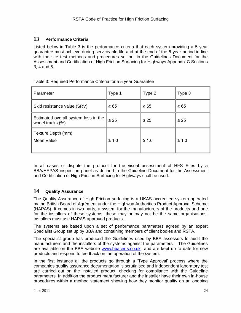
13 Performance Criteria
Listed below in Table 3 is the performance criteria that each system providing a 5 year guarantee must achieve during serviceable life and at the end of the 5 year period in line with the site test methods and procedures set out in the Guidelines Document for the Assessment and Certification of High Friction Surfacing for Highways Appendix C Sections 3, 4 and 6.
Table 3: Required Performance Criteria for a 5 year Guarantee
Parameter Type 1 Type 2 Type 3
Skid resistance value (SRV) ≥ 65 ≥ 65 ≥ 65
Estimated overall system loss in the wheel tracks (%)
≤ 25 ≤ 25 ≤ 25
Texture Depth (mm)
Mean Value
≥ 1.0
≥ 1.0
≥ 1.0
In all cases of dispute the protocol for the visual assessment of HFS Sites by a BBA/HAPAS inspection panel as defined in the Guideline Document for the Assessment and Certification of High Friction Surfacing for Highways shall be used.
14 Quality Assurance
The Quality Assurance of High Friction surfacing is a UKAS accredited system operated by the British Board of Agrément under the Highway Authorities Product Approval Scheme (HAPAS). It comes in two parts, a system for the manufacturers of the products and one for the installers of these systems, these may or may not be the same organisations. Installers must use HAPAS approved products.
The systems are based upon a set of performance parameters agreed by an expert Specialist Group set up by BBA and containing members of client bodies and RSTA.
The specialist group has produced the Guidelines used by BBA assessors to audit the manufacturers and the installers of the systems against the parameters. The Guidelines are available on the BBA website www.bbacerts.co.uk and are kept up to date for new products and respond to feedback on the operation of the system.
In the first instance all the products go through a ‘Type Approval’ process where the companies quality assurance documentation is scrutinised and independent laboratory test are carried out on the installed product, checking for compliance with the Guideline parameters. In addition the product manufacturer and the installer have their own in-house procedures within a method statement showing how they monitor quality on an ongoing
RSTA Code of Practice for High Friction Surfacing
June 2011 25
basis to control and deliver a quality system.
BBA carry out surveillance visits to installation sites on a regular basis including the taking of samples of the system, laid on to specially prepared slabs, for testing in the laboratory.
A Certificate is valid for 5 years, unless withdrawn for any reason.
In order to demonstrate best practice client organisations, including Local Authorities and Highways Agency, directly or through their maintenance contractor, are committed to only use BBA Accredited High Friction Surfacing Installers.
The use of BBA approved installers transfers the responsibility for the performance of an installation on a site to the installer and reduces the need for site testing and supervision by the client. This transfers some supervision costs from the client to the installer.
A key part of the systems is the use of trained and competent staff as described below.
No Quality Assurance system gives 100% guarantee that every aspect of the works will be perfect. A good working relationship between the client’s supervisors who are knowledgeable about the process being installed, and the contractor’s staff and operatives is very helpful to a good installation.
15 Training
The design of high friction applications and its execution is dependent on a wide range of factors and close attention to detail. Many engineers and technicians have been involved with high friction, however only a limited number have had any formal training in the design, specification and execution of the work. This lack of understanding of the products often results in inappropriate selection of materials, unsatisfactory preparation and installation leading ultimately to premature failure of the application.
The latest BBA Installers Scheme (Issued March 2010) addresses a number of training requirements for the operatives on site. This generally constitutes NVQ training for all types of application, i.e. Machine Applied Cold Epoxy Resin, Hand Applied Cold Epoxy Resin, and Hot Applied Thermoplastic.
Operatives should hold NVQ level 2 and CSCS cards.
Supervisors should hold NVQ level 3 and CSCS cards.
In addition Supervisors should maintain competency by attending an appropriate training course on High Friction Surfacing every 5 years. The RSTA run a training course on high friction surfacing and offer a Silver certificate as evidence of maintaining competency. Course details can be found at www.rsta-uk.org/calendar
It is the Association’s view that a full understanding of all processes throughout the industry and the workforce makes a fundamental contribution to achieving high quality durable high friction applications.
In addition to the BBA Installers Scheme the RSTA have now developed a training course that defines the minimum standard required for all personnel involved in the installation of high friction surfacing. This one day training course is an ADEPT requirement that all personnel involved within high friction surfacing must attend every 2 years to refresh them on Health and safety and key technical requirements of the processes so that good practices are reinforced.

RSTA Code of Practice for High Friction Surfacing
June 2011 26
Details of all courses and content can be obtained from the RSTA website www.rsta-uk.org/calendar .
16 Road Surface Treatments Association
Membership of the Road Surface Treatments Association is available to manufacturers, contractors and suppliers of Calcined Bauxite, binders, client bodies and specialist consultants. The unanimous decision of the Association is to contribute to and adopt this Code of Practice as an example of its commitment to quality in all its undertakings.
The attainment and maintenance of BBA HAPAS certification represents a substantial financial commitment to member companies. These costs will inevitably be reflected in the unit prices tendered for High Friction Surfacing however the client is compensated by purchasing a high quality system as required by Clause 924 in the Specification for Highway Works, plus an expected durability of 5 to 10 years.
BBA HAPAS certification is the minimum standard required for the installation of High Friction Surfacing. All contractors registered to a recognised trade association (i.e. RSTA or RSMA) will only install systems that have BBA HAPAS certification and comply with this Code of Practice as it is a mandatory requirement of Association membership.

RSTA Code of Practice for High Friction Surfacing
June 2011 27
APPENDIX A
Pre-Contract Checklist for the Client
1. Has the need for HFS been determined based upon the Local Authority’s Skid Resistance Policy?
2. Has the Commercial Vehicles traffic figure been obtained?
3. Has the existing road surface been inspected and found to be free from cracks, ruts or fatted areas? If these are present has resurfacing been organised? Has any old HFS to be removed?
4. Does the tender document only contain BBA HAPAS approved installers?
5. Has the main contractor only offered BBA HAPAS installers as required by the contract?
6. Has the Type (1, 2 or 3) of HFS been specified?
7. Has the programme date been fixed, do they exclude cold lay systems as a result of temperature constraints? Where applicable.
8. Are the traffic management arrangements fixed, including traffic orders if necessary?
9. Has all the information required of Paragraph 5 a) to j) above been supplied?
10. Has the Contract Review meeting been held with the contractor on site?
11. Has a start up meeting addressed all the necessary details as given in this document?
12. Has the training records for the staff and operatives to be employed been inspected?
13. Is the staffing for the supervision in place?
Pre-Contract Checklist for the Contractor
1. Has the contractor got all relevant site information i.e. location of schools, bus route, market days, events etc?
2. What type of traffic control is to be operated and is there enough labour to carry out the works in a safe and proper manner?
3. Have all labour received the appropriate training and got the appropriate training Certificates and CSCS cards?
4. Has the correct and adequate plant been allocated to carry out the works at and in the time available?
5. Is the Calcined Bauxite available when required?
6. Is the binder specified available when required?
7. Are calibration certificates available for thermometers, balances, measuring wheels or other measuring equipment?
8. Machine applied cold systems
a. Does the tanker to be used have a current spray bar test certificate?
b. Is there a chart in the tanker that will enable the correct rate of spread relative to the speed of the vehicle to be achieved?

RSTA Code of Practice for High Friction Surfacing
June 2011 28
c. Has the tanker metering device for the proportions been calibrated?
Contractor Checklist
1. Is the existing surface acceptable for the treatment and agreed with the client?
2. If the site is unacceptable, has the client agreed that the system shall go ahead without any guarantee of performance?
3. Has the site induction been carried out covering Health and Safety and technical issues for the site?
4. Does everybody understand the method of operation for the site?
5. Has the road surface been cleaned and swept to an acceptable standard?
6. Is the road clear of parked vehicles or any other obstructions?
7. Is the correct traffic management in place?
8. Has the extent of the site been marked out?
9. Are the correct signs approaching and at the site and for any diversion routes in place?
10. Has all necessary masking of cat eyes and street furniture been carried out?
11. Are the operatives all present and correct and wearing the relevant Personal Protection Equipment?
12. Is all the plant present and in safe working order?
13. Are the weather conditions appropriate to commence work i.e. high humidity levels, air temperatures?
14. Is the method statement and risk assessment available?
15. Is the planned method of operation safe, both to the operatives and the public?
16. Has the method of application been approved?
17. Has all the excess aggregate been swept up?
18. Have all on site tests and checks been carried out and recorded?
Post Contract Checklist
1 Have arrangements been made for post-contract inspections?
2 Has all the aftercare given in the relevant section above been planned and implemented?
3 Are signs being maintained in a satisfactory condition and placement and removed when required?
4 Has the required contract information being collected and documented?
5 Have arrangements been made for line replacement?
6 Are re-inspection arrangements clear and agreed?

RSTA Code of Practice for High Friction Surfacing
June 2011 29
APPENDIX B
GLOSSARY
ADHESION The property by means of which a binder sticks to the surface of a solid body, e.g. the road or aggregate.
BAR: An abbreviation for spray bar (see Spray bar)
BINDER: A liquid, comprised of resins mixed together
BOND: The adhesion between the binder and either the road surface or the applied Calcined Bauxite
CARPET TILE TEST: A test used as a means of checking the amount of resin applied to a road surface. Sections of carpet tile of known area, normally about 200mm square which have been pre-weighed, are placed on the road in front of the spray bar. Once the bar has passed over the tile, the tile is re-weighed. The quantity of binder delivered to the road surface is calculated and compared with the rate of spread specified for that section of road
C E N: The European Committee for Standardization or Comité Européen de Normalisation (CEN), is a non-profit organisation whose mission is to foster the European economy in global trading, the welfare of European citizens and the environment by providing an efficient infrastructure to interested parties for the development, maintenance and distribution of coherent sets of standards and specifications.
CLOSED-TEXTURED: A description of the surface condition of an asphalt road
COSHH: Control of Substances Hazardous to Health
COSHH ASSESSMENT: An assessment relating to the hazards to health represented by the use of materials and equipment
COST LIFE INDEX: The cost of the process expressed as the cost per square metre per annum of satisfactory life
CURE: The chemical reaction between liquid constituents that results in a solid binder
FATTING-UP: The result of an almost total embedment of chippings in the binder so a bitumen rich surface is formed
JET: An orifice through which binder passes from the tanker spray bar to the road surface
JOINTS: The point at which the installation from adjacent breeds meets the overlaps
MASK: An adhesive tape or other similar material used to cover cat’s eyes, road ironwork, etc, in such a way that after removal, they are free from binder or chippings

RSTA Code of Practice for High Friction Surfacing
June 2011 30
OPEN TEXTURED: A road surface consisting of aggregate of various sizes and proportions which, after compaction contains a high proportion of air voids
POLISHED STONE VALUE: (PSV): A Relative measure of the extent to which aggregate in the surface course polishes under traffic
PRE-PATCHING: The remedial measures carried out to make good defective areas of surfacing in advance of treatment
QA: An abbreviation for Quality Assurance
QUALITY ASSURANCE: Quality assurance, or QA for short, is the systematic monitoring and evaluation of the various aspects of a High Friction surfacing operation to maximize the probability that minimum standards of quality are being attained by the production process. Registration to BSEN ISO 9001 given to a contractor by a certification body indicates minimum standards are being attained
SKIDDING RESISTANCE: The frictional forces between tyre and road which are available to oppose skidding
SLOTTED JET: A jet nozzle fitted to a spray bar and formed in such a way that binder passing through it onto the road surface is in the shape of a fan
SPRAYER: An abbreviation for binder distributor
SPRAY BAR: The bar, carrying jets, that is fitted to the tanker and through which the binder is applied to the surface
TEXTURE DEPTH: A term used to denote the measure of projection of aggregates in a surface course
THERMOPLASTIC: The property of material by which their viscosity changes in relation to temperature change
THERMOSETTING: A material formed by an irreversible chemical reaction of two or more components which renders it resistant to temperature variations
UKAS National Measurement Accreditation Services.