code of practice 5 - academy for healthcare science welding, cutting and allied processes. general...
TRANSCRIPT
CODE OF PRACTICE 5
THE DESIGN AND CONSTRUCTION OF
MANIFOLDS USING ACETYLENE GAS
FROM 1.5 TO 25 bar
REVISION 3: 2016

BCGA CP 5 – Revision 3
CODE OF PRACTICE 5
THE DESIGN AND CONSTRUCTION OF MANIFOLDS USING
ACETYLENE GAS FROM 1.5 TO 25 bar
REVISION 3: 2016
Copyright © 2016 by British Compressed Gases
Association. First printed 1986. All rights reserved. No
part of this publication may be reproduced or transmitted in
any form or by any means, electronic or mechanical,
including photocopy, without permission from the
publisher:
BRITISH COMPRESSED GASES ASSOCIATION Registered office: 4a Mallard Way, Pride Park, Derby, UK. DE24 8GX
Company Number: 71798, England
Website:
www.bcga.co.uk
ISSN 0260 - 4809

BCGA CP 5 – Revision 3
PREFACE
The British Compressed Gases Association (BCGA) was established
in l971, formed out of the British Acetylene Association, which
existed since l901. BCGA members include gas producers, suppliers
of gas handling equipment and users operating in the compressed gas
field.
The main objectives of the Association are to further technology, to
enhance safe practice, and to prioritise environmental protection in
the supply and use of industrial, food and medical gases, and we
produce a host of publications to this end. BCGA also provides
advice and makes representations on behalf of its Members to
regulatory bodies, including the UK Government.
Policy is determined by a Council elected from Member Companies,
with detailed technical studies being undertaken by a Technical
Committee and its specialist Sub-Committees appointed for this
purpose.
BCGA makes strenuous efforts to ensure the accuracy and current
relevance of its publications, which are intended for use by
technically competent persons. However this does not remove the
need for technical and managerial judgement in practical situations.
Nor do they confer any immunity or exemption from relevant legal
requirements, including by-laws.
For the assistance of users, references are given, either in the text or
Appendices, to publications such as British, European and
International Standards and Codes of Practice, and current legislation
that may be applicable but no representation or warranty can be
given that these references are complete or current.
BCGA publications are reviewed, and revised if necessary, at five-
yearly intervals, or sooner where the need is recognised. Readers are
advised to check the Association’s website to ensure that the copy in
their possession is the current version.
This document has been prepared by BCGA Technical Sub-
Committee 3. This document replaces BCGA Code of Practice 5,
Revision 2: 2010. It was approved for publication at BCGA
Technical Committee 153. This document was first published on
17/02/2016. For comments on this document contact the Association
via the website www.bcga.co.uk.
BCGA CP 5 – Revision 3
CONTENTS
Section Page TERMINOLOGY AND DEFINITIONS
1
FOREWORD
4
1. INTRODUCTION
5
2. SCOPE
6
3. ACETYLENE GAS 6
3.1 General data 6
3.2 Materials of construction 7
3.3 Special conditions 7
3.4 Safety 7
3.5 Working ranges
9
4. MATERIALS 10
4.1 General 10
4.2 Recommended materials 10
4.3 Materials not allowed or recommended only under certain conditions
11
5. DESIGN OF MANIFOLDS 13
5.1 Manifold high pressure pipework 13
5.2 Pipe bore 14
5.3 System wall thickness to withstand detonation and reflection
occurring at any point
14
5.4 System to withstand undisturbed detonation with reinforcements
at reflection points
14
5.5 Temperatures of formation of liquid acetylene 15
5.6 Valves and seals 15
5.7 Pressure gauges 15
5.8 Regulators 16
5.9 High pressure hose assemblies 16
5.10 Limitations on gas draw-off rate
16
6. EQUIPMENT 17
6.1 High-pressure non-return valves 17
6.2 High-pressure hose assemblies 17
6.3 High-pressure stop valves 17
6.4 Manual or automatic quick-acting shut-off device 18
6.5 Pressure gauges 18
6.6 Pressure sensitive shut-off device 18
6.7 Main pressure regulator 18
6.8 Other devices 18
6.9 Safety signs and warning notices
18
7. PROTECTION
20
BCGA CP 5 – Revision 3
8. CLEANING
20
9. IDENTIFICATION
20
10. TESTING OF INSTALLATION, COMPONENTS AND
ASSEMBLIES
21
10.1 General 21
10.2 Pressure testing 21
10.3 Function tests
22
11. PROVISION OF INFORMATION
22
12. PRESSURE SYSTEMS SAFETY REGULATIONS
22
13. REFERENCES *
23
APPENDICES:
Appendix 1 Acetylene working ranges
26
Appendix 2 Mobile installation using bundle
27
Appendix 3 Permanent single cylinder supply installation
28
Appendix 4 Permanent installation cylinder manifold supply
29
Appendix 5 Permanent installation: bundle manifold – typical arrangement 30
* Throughout this publication the numbers in brackets refer to references in Section 13.
Documents referenced are the edition current at the time of publication, unless otherwise
stated.

1 BCGA CP 5 – Revision 3
TERMINOLOGY AND DEFINITIONS
Acetylene
manifold
system
A system of interconnected pipework in which compressed acetylene
gas is contained, and which connects to, but excludes, a cylinder.
The manifold system will contain an assembly of devices delivering a
regulated pressure under specified safe conditions, coupled to a user
pipeline system.
Composite
safety device
(Flashback
arrestor)
A unit which embodies 2 or more of the following devices:
Flame arrestor
Non-return valve
Temperature sensitive cut-off valve
Pressure sensitive cut-off valve
Cylinder bundle
/ Manifolded
cylinder pallet
(MCP)
An assembly of cylinders fastened together, interconnected by a
manifold for collective filling and gas withdrawal, and intended to be
transported as a single unit.
Decomposition The breakdown of acetylene into carbon and hydrogen.
Deflagration A flame produced by decomposition or combustion that travels into
the unreacted gas at less than sonic velocity.
The rate of propagation of a deflagration flame increases with the
density, the temperature and the turbulence of the unreacted gas.
Since these three parameters tend to increase as a deflagration
progresses, the rate of propagation is usually not steady but tends to
increase continually and sometimes leads to a detonation.
Detonation A flame produced by decomposition or combustion that travels into the
unreacted gas at a rate above sonic velocity, usually at several times
the speed of sound. Unlike a deflagration, where the pressure in front
of and behind the flame front rises at the same time, a detonation
involves a sharp difference in pressure between the reacted and
unreacted gas. The change from the low pressure of the unreacted gas
takes place in a shock wave at the front of the flame.
Flame arrestor A device which arrests a flame front (caused by flashback or
decomposition) and which is suitable for the most severe type of flame
which may occur, i.e. detonation.
High-pressure
hose assembly
(pigtail)
A flexible connection between the cylinder valve and manifold header.
It may be manufactured from tube or flexible elastomeric materials.
2 BCGA CP 5 – Revision 3
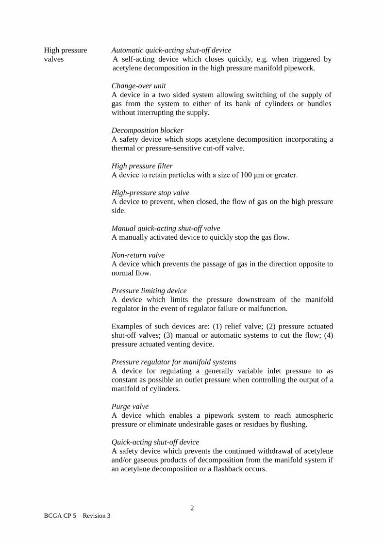
High pressure
valves
Automatic quick-acting shut-off device
A self-acting device which closes quickly, e.g. when triggered by
acetylene decomposition in the high pressure manifold pipework.
Change-over unit
A device in a two sided system allowing switching of the supply of
gas from the system to either of its bank of cylinders or bundles
without interrupting the supply.
Decomposition blocker
A safety device which stops acetylene decomposition incorporating a
thermal or pressure-sensitive cut-off valve.
High pressure filter
A device to retain particles with a size of 100 μm or greater.
High-pressure stop valve
A device to prevent, when closed, the flow of gas on the high pressure
side.
Manual quick-acting shut-off valve
A manually activated device to quickly stop the gas flow.
Non-return valve
A device which prevents the passage of gas in the direction opposite to
normal flow.
Pressure limiting device
A device which limits the pressure downstream of the manifold
regulator in the event of regulator failure or malfunction.
Examples of such devices are: (1) relief valve; (2) pressure actuated
shut-off valves; (3) manual or automatic systems to cut the flow; (4)
pressure actuated venting device.
Pressure regulator for manifold systems
A device for regulating a generally variable inlet pressure to as
constant as possible an outlet pressure when controlling the output of a
manifold of cylinders.
Purge valve
A device which enables a pipework system to reach atmospheric
pressure or eliminate undesirable gases or residues by flushing.
Quick-acting shut-off device
A safety device which prevents the continued withdrawal of acetylene
and/or gaseous products of decomposition from the manifold system if
an acetylene decomposition or a flashback occurs.
3 BCGA CP 5 – Revision 3
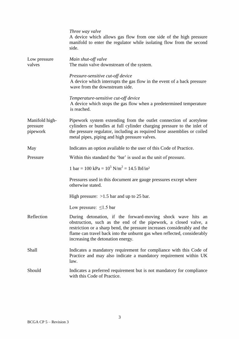
Three way valve
A device which allows gas flow from one side of the high pressure
manifold to enter the regulator while isolating flow from the second
side.
Low pressure
valves
Main shut-off valve
The main valve downstream of the system.
Pressure-sensitive cut-off device
A device which interrupts the gas flow in the event of a back pressure
wave from the downstream side.
Temperature-sensitive cut-off device
A device which stops the gas flow when a predetermined temperature
is reached.
Manifold high-
pressure
pipework
Pipework system extending from the outlet connection of acetylene
cylinders or bundles at full cylinder charging pressure to the inlet of
the pressure regulator, including as required hose assemblies or coiled
metal pipes, piping and high pressure valves.
May Indicates an option available to the user of this Code of Practice.
Pressure Within this standard the ‘bar’ is used as the unit of pressure.
1 bar = 100 kPa = 105 N/m
2 = 14.5 lbf/in²
Pressures used in this document are gauge pressures except where
otherwise stated.
High pressure: >1.5 bar and up to 25 bar.
Low pressure: ≤1.5 bar
Reflection During detonation, if the forward-moving shock wave hits an
obstruction, such as the end of the pipework, a closed valve, a
restriction or a sharp bend, the pressure increases considerably and the
flame can travel back into the unburnt gas when reflected, considerably
increasing the detonation energy.
Shall Indicates a mandatory requirement for compliance with this Code of
Practice and may also indicate a mandatory requirement within UK
law.
Should Indicates a preferred requirement but is not mandatory for compliance
with this Code of Practice.

4 BCGA CP 5 – Revision 3
FOREWORD
This document supersedes BCGA CP 5, Revision 2: 2010.
Revision 2 allowed for a working pressure between 1.5 to 17 bar. Revision 3 increased the
working pressure maximum limit from 17 bar to 25 bar. This was based on a practical reality.
The following were taken into consideration:
The working pressure of an acetylene cylinder is 19 bar.
Potentially cylinders can vary in temperature and therefore pressure whist in-use,
therefore a greater pressure than 19 bar may be introduced into the pressure system. The
pressure system temperature will also vary and designing a system for 25 bar ensures a
reasonable factor of safety.
Although the pressure in filling manifolds is not likely to exceed 25 bar, the
pressures generated in the event of an acetylene decomposition are accounted for in the
design of manifolds and the associated components and pipes.
BS EN ISO 14114 (22), Gas welding equipment. Acetylene manifold systems for
welding, cutting and allied processes. General requirements, quotes high pressure as
being between 1.5 bar and 25 bar, and all system components are expected to meet this
upper limit.
EIGA IGC Document 123 (27), Code of Practice Acetylene, quotes 25 bar as the
high pressure limit.

5 BCGA CP 5 – Revision 3
CODE OF PRACTICE 5
THE DESIGN AND CONSTRUCTION OF MANIFOLDS USING
ACETYLENE GAS FROM 1.5 TO 25 bar
1. INTRODUCTION
Acetylene has unique properties. Acetylene is an extremely flammable gas and can burn in the
presence of air or oxygen. This generates very high flame temperatures, which is the reason
why acetylene is so effective for cutting and welding. The acetylene (C2H2) molecule,
however, if initiated by heat exposure of a cylinder in a fire, or through excessive fill pressure,
can also decompose breaking up into one hydrogen molecule and two carbon atoms. This
reaction delivers much less energy than combustion but can, in some circumstances, be strong
enough to rupture a cylinder. Additionally, whereas acetylene is very soluble in the solvents
used in dissolved acetylene cylinders, hydrogen, when released through decomposition, is
much less soluble; giving a significant and irreversible pressure rise within the cylinder, which
can be sufficient to cause its rupture. For these reasons the maximum working pressure of an
acetylene cylinder is kept relatively low at 19 bar. Consequently, manifolds connected to an
acetylene cylinder are designed and constructed to operate at pressures between 1.5 and 25 bar.
In use, acetylene is delivered to the end user at pressures up to 1.5 bar.
NOTE: The design of a dissolved acetylene cylinder is also important. Each cylinder is
filled with a porous material, which is a very effective obstacle for energy and fluid flow. A
solvent is then added to the porous material, (typically acetone or dimethylformamide (DMF)),
and the acetylene gas is then dissolved in this solvent. The dissolved acetylene cylinder is thus
a complex system comprising a number of components interacting with each other. This
system keeps acetylene in a safe condition inside the cylinder.
As a consequence of this potential hazard, acetylene is subject to specific legislation.
Following a major review of legislation in 2014, acetylene was placed under The Acetylene
Safety (England and Wales and Scotland) Regulations (6). This revision complies with these
new regulations.
The manufacture of compressed acetylene gas; the compression of acetylene at pressures equal
to or greater than 0.62 bar; or the filling of a cylinder with compressed acetylene gas cannot be
carried out without a licence issued by the Health and Safety Executive (HSE). The licensee
shall comply with the conditions of the licence and comply with the requirements of the
Acetylene Safety (England and Wales and Scotland) Regulations (6), Schedule 1.
The content of this publication is in line with advice from the HSE. For more details refer to
http://www.hse.gov.uk/fireandexplosion/acetylene.htm and leaflet HSE INDG 327 (10),
Working safely with acetylene.
The Dangerous Substances and Explosive Atmospheres Regulations (DSEAR) (4) requires that
employers undertake a risk assessment and put in place suitable controls where an explosive
atmosphere may occur, such as where flammable gases are used or stored.

6 BCGA CP 5 – Revision 3
It is recommended that users of oxy-acetylene gas processes ensure that all new installations,
or modifications to existing installations, comply with this Code of Practice for the products or
services involved.
It is pointed out that this code represents the BCGA’s views of minimum requirements for safe
practices, reference should be made to Section 13 for further details on specific standards or
Regulations.
2. SCOPE
This Code of Practice is for the design and construction of acetylene gas manifolds with a
pressure range between 1.5 bar (21.8 lbf/in²) to a maximum working pressure of 25 bar (362.6
lbf/in²).
This code applies to acetylene cylinder manifold systems in which acetylene single cylinders
or acetylene bundles are coupled for collective gas withdrawal. The manifold system extends
from the cylinder outlet valve, or the bundle outlet connection, to the outlet connection of the
main shut-off valve. It applies to the manifold and other sections of a total installation, which
are within Working Range III, refer to Section 3.5.
The Code also makes recommendations for ancillary equipment normally associated with
acetylene manifolds. Each manifold shall be installed in conjunction with the pressure control,
safety devices and other equipment detailed in the BCGA CP 6 (29), The safe distribution of
acetylene in the pressure range 0 to 1.5 bar.
This Code of Practice takes into account the requirements of the Pressure Systems Safety
Regulations (3) and BS EN ISO 14114 (22), Gas welding equipment. Acetylene manifold
systems for welding cutting and allied processes. General requirements.
The European Industrial Gases Association (EIGA) Document 123 (27), Code of Practice
Acetylene, provides comprehensive guidance on the safety requirements for acetylene.
This Code of Practice excludes manifolds for acetylene cylinder filling, refer to EIGA
Document 123 (27).
3. ACETYLENE GAS
3.1 General data
Chemical symbol C2H2
Cylinder ground colour Maroon (RAL 3007)
Flammable / non-flammable Flammable
Lighter / heavier than air Slightly lighter NOTE 1
Colour Colourless
Odour Some sources produce a slight odour NOTE 2
Taste Tasteless
Toxicity Non-toxic NOTE 2
Corrosivity Non-corrosive
7 BCGA CP 5 – Revision 3
NOTES:
1. Mixtures of acetylene and acetone vapour can be heavier than air.
2. Commercial supplies of acetylene do contain trace impurities which are
toxic and which can also give rise to a slight odour. Precautions should be
taken to avoid inhaling acetylene gas.
3.2 Materials of construction
The properties of acetylene limit the choice of materials that can be used in the
construction of its piping systems and components. Refer to Section 4.
3.3 Special conditions
Acetylene differs from other fuel gases, such as natural gas, propane and butane, because
of its ability to decompose in the absence of air or oxygen, when initiated by a source of
heat energy. This decomposition reaction may proceed through deflagration to
detonation depending on the gas pressure and pipe dimensions. The effects of an
acetylene decomposition are similar to fuel gas-oxygen explosions, resulting in a loud
noise, bright flame, rise in temperature and pressure and soot formation.
The flammability range of acetylene in air is between 2.2 % to 85 %.
Decomposition in a gas cylinder will only occur after exposure to temperatures in excess
of 350 °C. Factors, such as the presence of air, rust particles etc., can significantly lower
this temperature in a manifold system.
NOTE: Mechanical shock alone to a cold acetylene cylinder, which remains intact
and has not been exposed to fire, cannot initiate decomposition.
Some materials, even in small quantities, can form compounds with acetylene under
certain conditions and pose a risk or are liable to initiate decomposition. Refer to
Section 4.
3.4 Safety
As a flammable atmosphere may exist a risk assessment shall be carried out in
compliance with DSEAR (4) and suitable controls put in place. If an explosive
atmosphere may exist signage shall be displayed, refer to Section 6.9.
NOTE: Guidance on the preparation of Risk Assessments under DSEAR (4) is
contained in BCGA GN 13 (32), DSEAR Risk Assessment. Additional guidance is
provided by the HSE, refer to HSE L138 (9), Dangerous substances and explosive
atmospheres DSEAR 2002. Approved Codes of Practice and Guidance, and HSE INDG
370 (11), Controlling Fire & Explosion risks in the workplace. A brief guide to DSEAR.
The Dangerous Substances (Notification and Marking of Sites) Regulations (1) require,
that if you hold 25 tonnes or more of a dangerous substance then you are required to
notify the enforcing authority and the local Fire and Rescue Service, and mark sites at the
access points to warn of the presence or possible presence of dangerous substances.
8 BCGA CP 5 – Revision 3
Fire safety. A responsible person shall carry out a Fire Safety Risk Assessment on all
storage sites and areas where acetylene is used, the findings from which are to be
incorporated into the Site Fire Safety Management Plan that is to be implemented and
maintained. As necessary, advice should be sought from the local fire authority. Each
site should keep a record of the location of its hazardous store(s), this is to be made
available to the emergency services in the event of an incident. Refer to The Regulatory
Reform (Fire Safety) Order (5). Fire-fighting facilities as identified in the Site Fire
Safety Management Plan shall be provided.
Although acetylene is non-toxic, acetylene-enriched atmospheres can cause asphyxiation
through the depletion of oxygen.
Appropriate safety signs and warning notices shall be displayed, refer to Section 6.9.
Acetylene vented from safety / pressure relief devices and purge points should be
discharged to an external area specifically classified for acetylene where there is no risk
of ignition. All discharge pipes or orifices to the open air shall be designed and made in
such a way as to avoid choking, obstruction or frictional pressure drop. Safety / pressure
relief device discharge pipes should be separate and connection to a manifold should be
avoided. The design of pipework shall take into account the working range of the
acetylene for the pressures at the discharge point. The vent pipes and outlets shall
prevent the ingress of contaminants and the accumulation of water, including that from
snow, rain and condensation. Contaminants, as well as water accumulation that may lead
to the formation of ice, could potentially cause blockages. Appropriate safety signs and
warning notices shall be displayed at the vent outlet and drain points.
As a flammable atmosphere may exist at the vent outlet(s) a risk assessment shall be
carried out in compliance with DSEAR (4) and suitable controls put in place.
Further information on venting is available in and EIGA Document 30 (25), Disposal of
gases, and EIGA Document 123 (27).
Systems shall be effectively bonded and earthed against the build-up of static electricity,
refer to BS 5958 (16), Code of practice for control of undesirable static electricity.
All piping and building components shall be protected from electrostatic charges by
maintaining an electrical conductivity with a maximum resistance of 106 ohm.
The use of electrical equipment in an area where a flammable atmosphere may exist
should be kept to the minimum necessary for the safe and practical operation of the
installation. All such electrical equipment shall be suitable for use with acetylene [Gas
Group IIC, Temperature Classification T2]. The equipment shall be designed, installed
and maintained in accordance with BS EN 60079 (24), Electrical apparatus for explosive
gas atmospheres.
The repair of electrical equipment within a hazardous area shall be carried out in
accordance with BS EN 60079 Part 19 (24), Electrical apparatus for explosive gas
atmospheres. Repair and overhaul for apparatus used in explosive atmospheres (other
than mines or explosives).

9 BCGA CP 5 – Revision 3
Pipework shall have a separation distance of at least 50 mm from electrical systems.
Pipework shall be purged out of service with an inert gas, such as nitrogen, until the
residual acetylene is below 0.6 %. Pipework shall be purged into service using an inert
gas, such as nitrogen, until the oxygen level is less than 0.1 %. Carbon dioxide is not
recommended due to the risk of a static charge.
Pipework shall be segregated from other pipework carrying oxidising gases and sources
of ignition to prevent combustion occurring.
Distribution pipework and associated safety components shall comply with BCGA CP 6
(29).
Decomposition can be initiated in the event of a flashback occurring. The cylinder /
mass combination has been designed to contain and deal with a single flashback - but
repeated flashbacks into a cylinder caused by faulty equipment or operation can
ultimately lead to decomposition which could overcome the cylinder's ability to
withstand such. A cylinder which is known to have suffered multiple flashbacks should
be withdrawn from use and returned to the gas supplier with a clear notice as to what is
known. To prevent a flashback the use of flashback arrestors is mandatory. They shall
be fitted within 1 metre downstream of the regulator.
Each system shall be fitted with a non-return device, to prevent the flow of gas towards
the cylinder, and a quick-acting shut-off device, both fitted as close as is reasonably
practical to the acetylene manifold, or where no manifold is used, to the cylinder.
For further information on the safe distribution and use of acetylene refer to BCGA CP 6
(29).
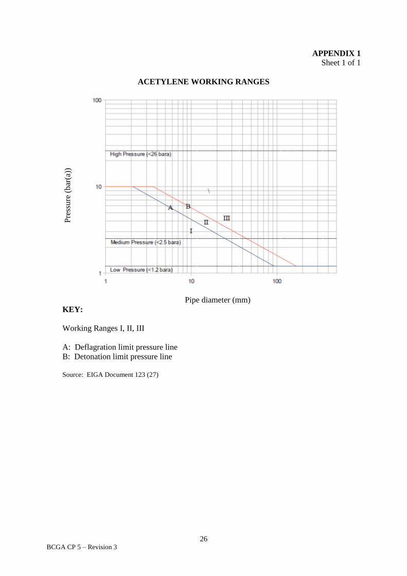
3.5 Working ranges
(EIGA) Document 123 (27) identifies the types of hazard normally present in an
acetylene installation. The type of hazard, under certain conditions, is determined by
pressure, internal pipe diameter and pre-detonation distance. These hazards are
categorised into three working ranges, which are simply identified by a graph relating
pipeline pressure to pipe diameter, refer to Appendix 1.
Working Range I
Acetylene decomposition hazard is slight, but not impossible.
Working Range II
On ignition, acetylene decomposition in form of deflagration may occur.
Working Range III
On ignition, acetylene decomposition will start as a deflagration and in
sufficiently long pipelines transition to detonation may occur.
The internal diameter of the pipe and the maximum gas pressure will place each pipeline
into one of the Working Ranges. The material used in the construction and the size of
the pipeline will depend on the Working Range.
10 BCGA CP 5 – Revision 3
4. MATERIALS
4.1 General All materials used, including non-metallic parts for joints, seals, diaphragms, hoses, etc.,
shall conform to BS EN ISO 9539 (19), Gas welding equipment. Materials for
equipment used in gas welding, cutting and allied processes, and be resistant to the
action of the acetylene, its impurities and other substances (e.g. acetone or DMF, i.e.
solvent from the acetylene cylinder) under the operating conditions (e.g. temperature,
pressure) to which they are subjected and, where applicable, to atmospheric corrosion.
Materials which do not have adequate resistance may be used provided they are suitably
protected (by coatings such as paint, baked enamel and sprayed metal) and provided that
damage to or breakdown of the protection cannot give rise to the formation of dangerous
compounds or conditions.
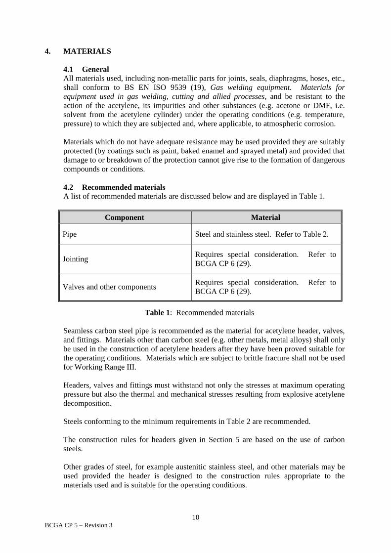
4.2 Recommended materials
A list of recommended materials are discussed below and are displayed in Table 1.
Component Material
Pipe Steel and stainless steel. Refer to Table 2.
Jointing Requires special consideration. Refer to
BCGA CP 6 (29).
Valves and other components Requires special consideration. Refer to
BCGA CP 6 (29).
Table 1: Recommended materials
Seamless carbon steel pipe is recommended as the material for acetylene header, valves,
and fittings. Materials other than carbon steel (e.g. other metals, metal alloys) shall only
be used in the construction of acetylene headers after they have been proved suitable for
the operating conditions. Materials which are subject to brittle fracture shall not be used
for Working Range III.
Headers, valves and fittings must withstand not only the stresses at maximum operating
pressure but also the thermal and mechanical stresses resulting from explosive acetylene
decomposition.
Steels conforming to the minimum requirements in Table 2 are recommended.
The construction rules for headers given in Section 5 are based on the use of carbon
steels.
Other grades of steel, for example austenitic stainless steel, and other materials may be
used provided the header is designed to the construction rules appropriate to the
materials used and is suitable for the operating conditions.

11 BCGA CP 5 – Revision 3
For welded headers the materials chosen shall have suitable welding characteristics and
the strength of the weld shall be not less than that of the material.
Minimum tensile strength (Rm) Minimum % elongation after fracture
320 N/mm²
mR
8400 or 16
whichever is the greater
Table 2: Steel. Minimum requirements.
4.3 Materials not allowed or recommended only under certain conditions
Certain metals, such as copper, silver and mercury, can form compounds with acetylene
under certain conditions that even in small quantities may explode when subjected to
friction or shock.
This means that the unrestricted use of these metals even, for instance, as a brazing
alloy, could introduce the possibility of acetylene decomposition.
Studies of the conditions of formation of the explosive acetylene compounds have
shown that the likelihood of their formation increases with the copper or silver content
of the alloy, together with flux residues in the presence of acetylene. Other metals, such
as aluminium, magnesium or zinc, may suffer severe corrosion under the influence of the
impurities that occur in un-purified acetylene.
For these or other reasons, the restrictions and conditions stated in Table 3 shall be
observed.

12 BCGA CP 5 – Revision 3
Material Conditions for use
Copper and Copper
Alloys containing
more than 70% of
copper
Not allowed.
Mercury
Not allowed.
Copper Alloys
containing up to 70 %
copper
Permitted. Special consideration should be given to the use of
copper alloy for filters, etc. in view of the large surface in contact
with acetylene and for parts in contact with moist unpurified
acetylene. Any heat or chemical / corrosion process which
produces copper enrichment on the surface of the copper alloy
shall be avoided, or copper alloy shall not be used.
Silver Not allowed.
Silver Alloys Suitable for brazing provided that the silver content does not
exceed 43 % and the copper content does not exceed 21 % and
that the gap between the two parts to be brazed does not exceed
0.3 mm. Special care shall be taken to minimise the area of filler
metal exposed to acetylene and to remove as far as practical all
traces of flux.
For additional information refer to BS EN ISO 9539 (19).
Aluminium
Aluminium Alloys
Magnesium Alloys
Zinc Alloys
Not recommended for components that come into contact with
moist acetylene contaminated with lime or ammonia (un-purified
generator gas).
Zinc Suitable as external anti-corrosion protective coating.
Glass Should generally be used only for sight glasses. Such devices
should either be protected against external damage or designed
so that breakage will not cause a hazard.
Organic materials May be used if it has been proved that they are resistant against
acetylene, solvents and impurities.
For fittings, valve housing and similar components, the ferrous materials listed below
may be used:
Grey cast iron
Malleable cast iron
Spheroidal graphite cast iron
Wrought iron
Table 3: Materials not allowed or recommended only under certain conditions
13 BCGA CP 5 – Revision 3
5. DESIGN OF MANIFOLDS
An acetylene manifold shall be designed, manufactured and subsequently operated to prevent,
so far as is reasonably practical:
The uncontrolled combustion of acetylene gas;
The decomposition of acetylene gas; and
The formation of acetylene-derived compounds that pose a risk or are liable to
initiate decomposition of acetylene gas.
As such it shall take account of the Working Range; determined at Section 3.5
An acetylene manifold shall be designed and manufactured to:
Withstand the thermal and mechanical stresses of any decomposition of the
acetylene gas it contains; or
Dissipate or direct the thermal and mechanical stresses of any decomposition of
the acetylene gas that it contains.
The design of an acetylene manifold shall prevent the mixture of air, or oxygen, within the
manifold. The filling manifolds and their ancillary equipment including valves, flexible hoses,
and connections, shall be designed for safe operation in working range III (detonation
resistance). In use, the manifold shall not be subjected to any pressure greater than that in the
attached cylinder / bundle (maximum 25 bar).
EIGA Document 123 (27) covers the basic requirements for the safe and correct design and
maintenance of an acetylene plant as well as customer installations and provides detailed
information on the calculations referenced in Section 5.
5.1 Manifold high pressure pipework
Acetylene manifolds shall conform to the requirements of BS EN ISO 14114 (22) and
this Code of Practice. The manifold shall, where practical, consist of rigid pipework.
Refer to Section 5.9.
Pipelines or sections of pipelines used in the construction of the manifold shall be
designed by calculation to withstand detonation. The length of manifolds, pipes and the
overall manifold configuration shall be kept to a minimum and the design of the
pipework should minimise the ingress of air into the system.
An acetylene detonation travels along the pipeline as a shock wave. Particularly high
stresses are caused at or near those places of the pipeline where the shock wave will be
reflected. Places of reflection may be sharp bends, valves and closed ends of pipes.
Ring mains are not recommended.
There are two methods of designing a pipe system based upon calculated wall thickness:
(i) Designing the whole system to withstand reflection occurring at any point.
14 BCGA CP 5 – Revision 3
(ii) Designing straight parts of the line to withstand undisturbed detonation with
increased wall thickness at places where reflection could occur.
To connect the cylinder or bundle outlet to the manifold inlet, all high pressure pipework
or coiled metal pipe shall be in accordance with BS EN ISO 10961 (20), Gas cylinders.
Cylinder bundles. Design, manufacture, testing and inspection, and high pressure hoses
shall be in accordance with BS EN ISO 14113 (21), Gas welding equipment. Rubber
and plastics hose and hose assemblies for use with industrial gases up to 450 bar (45
MPa).
5.2 Pipe bore
All pipe internal diameters shall be kept to the practical minimum necessary to sustain
the flow rates required, and shall not exceed 25 mm for pressures above 1.5 bar.
5.3 System wall thickness to withstand detonation and reflection occurring at any
point
Pipe wall thicknesses shall be determined according to the methods and calculations
detailed in BS EN ISO 10961 (20). Specifically BS EN ISO 10961: 2010, Annex B
3.4.2.
5.4 System to withstand undisturbed detonation with reinforcements at reflection
points
The wall thickness of the pipes is calculated by the method described in Section 5.3.
Pipes with wall thickness calculated in this way should be used only for straight parts of
the line. Pipe bends with a bending radius of five times the internal diameter of the pipe
or more, can be considered as straight lines if the strength of the bent pipe is comparable
to that of the straight pipe.
Reinforcement of the wall thickness shall be employed at points of full reflection, e.g.
blind bends, valves and bends with bending radius of less than five times the internal
diameter (sharp bends). Tee junctions are points of partial reflection, not full reflection.
The reinforcements shall increase the total wall thickness to at least twice the calculated
wall thickness.
For blind bends and sharp bends the reinforcements must cover a pipe length at least
equal to three times the internal diameter of the pipe. Where a point of reflection is
protected by a flame arrestor which is within the pre-detonation distance from the point
of reflection, reinforcement at that point is unnecessary.
There shall be no sudden change in the internal bore of the pipeline; this is particularly
important when designing reinforcements.
All pipework shall be adequately supported and protected from damage or vibration.
Acetylene pipelines shall not be used as an electrical earth or conductor and shall be
separated from electrical installations by a minimum air gap of 50 mm.
15 BCGA CP 5 – Revision 3
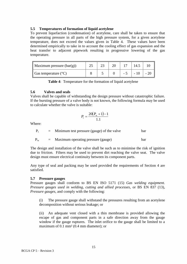
5.5 Temperatures of formation of liquid acetylene To prevent liquefaction (condensation) of acetylene, care shall be taken to ensure that
the operating pressure in all parts of the high pressure system, for a given acetylene
temperature, does not exceed the values given in Table 4. These values have been
determined empirically to take in to account the cooling effect of gas expansion and the
heat transfer to adjacent pipework resulting in progressive lowering of the gas
temperature.
Maximum pressure (bar(g)) 25 23 20 17 14.5 10
Gas temperature (°C) 8 5 0 - 5 - 10 - 20
Table 4: Temperature for the formation of liquid acetylene
5.6 Valves and seals
Valves shall be capable of withstanding the design pressure without catastrophic failure.
If the bursting pressure of a valve body is not known, the following formula may be used
to calculate whether the valve is suitable:
1.1
1120 w
t
PP
Where:
Pt = Minimum test pressure (gauge) of the valve
bar
Pw = Maximum operating pressure (gauge) bar
The design and installation of the valve shall be such as to minimise the risk of ignition
due to friction. Filters may be used to prevent dirt reaching the valve seat. The valve
design must ensure electrical continuity between its component parts.
Any type of seal and packing may be used provided the requirements of Section 4 are
satisfied.
5.7 Pressure gauges Pressure gauges shall conform to BS EN ISO 5171 (15) Gas welding equipment.
Pressure gauges used in welding, cutting and allied processes, or BS EN 837 (13),
Pressure gauges, and comply with the following:
(i) The pressure gauge shall withstand the pressures resulting from an acetylene
decomposition without serious leakage; or
(ii) An adequate vent closed with a thin membrane is provided allowing the
escape of gas and component parts in a safe direction away from the gauge
window if the gauge ruptures. The inlet orifice to the gauge shall be limited to a
maximum of 0.1 mm² (0.4 mm diameter); or

16 BCGA CP 5 – Revision 3
(iii) The pressure gauge is protected against over pressurisation by a gauge
protector or similar device.
The dial shall be marked ‘ACETYLENE’.
5.8 Regulators Regulators shall conform to BS EN ISO 7291 (18), Gas welding equipment. Pressure
regulators for manifold systems used in welding, cutting and allied processes up to 30
MPa (300 bar).
They shall withstand the pressure resulting from acetylene decomposition without
bursting of the body.
Special care shall be taken to ensure that the diaphragm and seat materials comply with
Section 4.
When regulators do not have an integral filter then separate line filters shall be used.
5.9 High pressure hose assemblies Flexible hoses shall only be used when rigid pipes are not practical. Where flexible hose
is necessary, the length and diameter of the hose shall be kept to a minimum that is
practical and the hose should be protected against external damage.
Hose fittings should be carefully designed to avoid sudden changes in diameter; where
there is a change in diameter a gradual taper should be made.
Hoses shall have a minimum burst pressure of 1000 bar and they shall resist an acetylene
decomposition of high pressure acetylene at an initial pressure of 25 bar.
When hoses are installed, the resistance between the two end fittings shall not exceed
106 ohms to give protection against electrostatic charging.
Hose assemblies shall conform to BS EN ISO 14113 (21), or an equivalent standard.
The hose shall consist of either:
(i) A rubber or plastics lining and reinforcement consisting of one or more
layers and an outer protective cover of permeable material or perforated rubber or
plastics; or
(ii) A rubber or plastics lining and reinforcement consisting of one or more
layers of stainless steel wire braid and / or other corrosion and abrasion resistant
material, which is also designed as an outer protective cover.
All hose shall be compatible with acetylene and resistant to solvent attack, from acetone
or DMF.
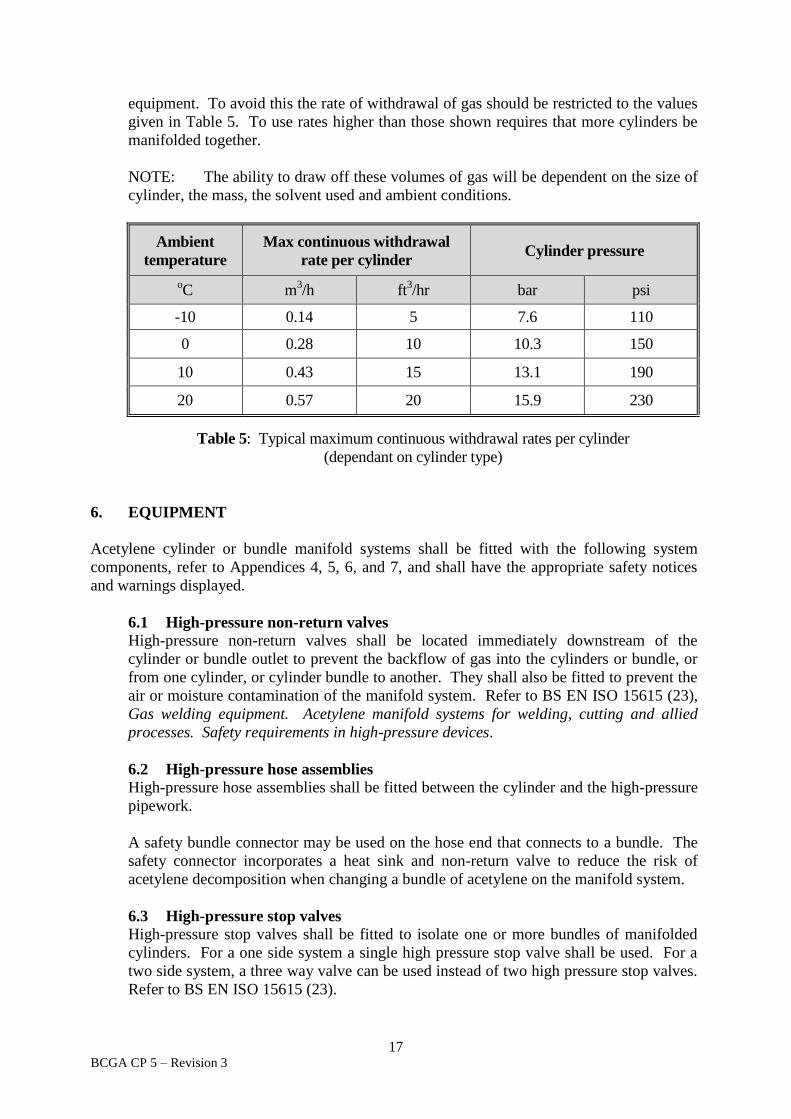
5.10 Limitations on gas draw-off rate If acetylene gas is drawn off from cylinders too rapidly there is a possibility of acetone
or DMF being mixed with the gas, and then causing malfunction of downstream
17 BCGA CP 5 – Revision 3
equipment. To avoid this the rate of withdrawal of gas should be restricted to the values
given in Table 5. To use rates higher than those shown requires that more cylinders be
manifolded together.
NOTE: The ability to draw off these volumes of gas will be dependent on the size of
cylinder, the mass, the solvent used and ambient conditions.
Ambient
temperature
Max continuous withdrawal
rate per cylinder Cylinder pressure
oC m
3/h ft
3/hr bar psi
-10 0.14 5 7.6 110
0 0.28 10 10.3 150
10 0.43 15 13.1 190
20 0.57 20 15.9 230
Table 5: Typical maximum continuous withdrawal rates per cylinder
(dependant on cylinder type)
6. EQUIPMENT
Acetylene cylinder or bundle manifold systems shall be fitted with the following system
components, refer to Appendices 4, 5, 6, and 7, and shall have the appropriate safety notices
and warnings displayed.
6.1 High-pressure non-return valves High-pressure non-return valves shall be located immediately downstream of the
cylinder or bundle outlet to prevent the backflow of gas into the cylinders or bundle, or
from one cylinder, or cylinder bundle to another. They shall also be fitted to prevent the
air or moisture contamination of the manifold system. Refer to BS EN ISO 15615 (23),
Gas welding equipment. Acetylene manifold systems for welding, cutting and allied
processes. Safety requirements in high-pressure devices.
6.2 High-pressure hose assemblies
High-pressure hose assemblies shall be fitted between the cylinder and the high-pressure
pipework.
A safety bundle connector may be used on the hose end that connects to a bundle. The
safety connector incorporates a heat sink and non-return valve to reduce the risk of
acetylene decomposition when changing a bundle of acetylene on the manifold system.
6.3 High-pressure stop valves
High-pressure stop valves shall be fitted to isolate one or more bundles of manifolded
cylinders. For a one side system a single high pressure stop valve shall be used. For a
two side system, a three way valve can be used instead of two high pressure stop valves.
Refer to BS EN ISO 15615 (23).

18 BCGA CP 5 – Revision 3
6.4 Manual or automatic quick-acting shut-off device
A manual quick-acting shut-off valve, or an automatic quick-acting shut-off device, shall
be fitted to prevent the continued withdrawal of acetylene and/or gaseous products of
decomposition from the manifold system if an acetylene decomposition or flashback
occurs. To be fitted upstream of the manifold regulator. Refer to BS EN ISO 15615
(23).
NOTE: Manual quick-acting shut-off valves can only be used on systems of up to 2
x 8 cylinders. Any system greater in capacity shall incorporate an automatic quick
acting shut-off valve in accordance with BS EN ISO 15615 (23).
6.5 Pressure gauges
Pressure gauges shall be fitted on the upstream and downstream side of the pressure
regulators. They may be an integral part of the regulator or separate devices.
6.6 Pressure sensitive shut-off device
A pressure sensitive shut-off valve, or a relief device, shall be fitted to limit the pressure
downstream of the manifold regulator. Where this device is a pressure sensitive shut-off
valve which is fitted in conjunction with a pressure differential auto-changeover
manifold of two (separate) stages of regulation, it may be fitted after the primary
regulator and before the secondary / final regulator.
6.7 Main pressure regulator
A manifold regulator shall be fitted to reduce the cylinder pressure to the distribution
pipeline pressure. Refer to Section 5.8.
6.8 Other devices
Any device situated in the high-pressure system shall conform to the design
requirements of this Code.
The items fitted to the low-pressure side of the manifold do not form part of this Code.
They shall conform to the requirements of BCGA CP 6 (29).
6.9 Safety signs and warning notices
Gas cylinder stores, or stores where acetylene gas cylinders are connected to a manifold,
shall have adequate signage to provide warnings and safety information, refer to BCGA
GN 2 (31), Guidance for the storage of gas cylinders in the workplace. Outlets from
manifolds and the distribution pipework shall be appropriately identified.
Signage shall comply with:
The Health and Safety (Safety Signs and Signals) Regulations (2).
BS ISO 7010 (17), Graphical symbols. Safety colours and safety signs.
Registered safety signs.
For additional advice refer to HSE L64 (7), Safety signs and signals. The Health and
Safety (Safety Signs and Signals) guidance on regulations.
19 BCGA CP 5 – Revision 3
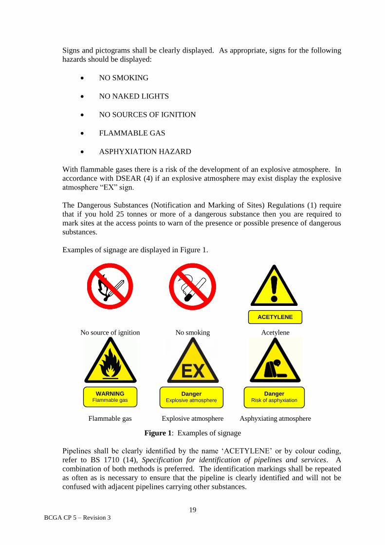
Signs and pictograms shall be clearly displayed. As appropriate, signs for the following
hazards should be displayed:
NO SMOKING
NO NAKED LIGHTS
NO SOURCES OF IGNITION
FLAMMABLE GAS
ASPHYXIATION HAZARD
With flammable gases there is a risk of the development of an explosive atmosphere. In
accordance with DSEAR (4) if an explosive atmosphere may exist display the explosive
atmosphere “EX” sign.
The Dangerous Substances (Notification and Marking of Sites) Regulations (1) require
that if you hold 25 tonnes or more of a dangerous substance then you are required to
mark sites at the access points to warn of the presence or possible presence of dangerous
substances.
Examples of signage are displayed in Figure 1.
No source of ignition No smoking Acetylene
Flammable gas Explosive atmosphere Asphyxiating atmosphere
Figure 1: Examples of signage
Pipelines shall be clearly identified by the name ‘ACETYLENE’ or by colour coding,
refer to BS 1710 (14), Specification for identification of pipelines and services. A
combination of both methods is preferred. The identification markings shall be repeated
as often as is necessary to ensure that the pipeline is clearly identified and will not be
confused with adjacent pipelines carrying other substances.
Danger Risk of asphyxiation
Danger Explosive atmosphere
WARNING Flammable gas
ACETYLENE
20 BCGA CP 5 – Revision 3
In addition a notice shall be displayed showing:
(i) Actions to take in the event of an emergency.
(ii) The site operator’s routine contact details.
(iii) Emergency contact information including an emergency phone number, for
example of the gas supplier and/or the site operator.
(iv) The emergency services phone number.
This information should also be available at a control point, for example the site control
room or site security.
7. PROTECTION
Acetylene manifolds are generally located in an external area and shall be designed for such
use. Protection against external corrosion may be required.
8. CLEANING
Acetylene manifolds shall be cleaned internally during manufacture to remove all traces of
mill scale and foreign matter.
9. IDENTIFICATION
Acetylene manifolds shall be clearly marked with the following information:
Type of gas: Acetylene.
Name, trademark or logo of manufacturer or distributor.
Maximum regulated pressure (bar, MPa).
Maximum flow of the system at 15 °C (m3/h)
Minimum and maximum operation temperature (-20 °C / +60 °C).
Year and month of manufacture/installation.
Reference to BS EN ISO 14114 (22)

21 BCGA CP 5 – Revision 3
10. TESTING OF INSTALLATION, COMPONENTS AND ASSEMBLIES
10.1 General
The installation shall be checked on completion to ensure that all connections are secure
and that any blanks or fittings necessary for subsequent pressure testing are of adequate
design and are securely fitted.
All high pressure and low pressure manifold components shall be tested for their
resistance to the pressures likely to be encountered in acetylene service.
Pressure gauges and safety devices may have to be removed before testing.
Parts which have been tested prior to installation may be excluded from the pressure
strength test.
10.2 Pressure testing
The completed system shall be pressure tested. Where practicable a hydraulic strength
test should be carried out followed by a leak test. When a hydraulic test is not
practicable or is precluded because of the design of the system, the strength test may be
carried out pneumatically, commencing with a leak test.
NOTE: Hydraulic testing is considered to be a far safer method than pneumatic
testing as the potential release of stored energy upon component failure is substantially
less.
Guidance on pressure testing is given in HSE Guidance Note GS4 (12), Safety in
pressure testing, and in BCGA CP 4 (28), Industrial gas cylinder manifolds and
distribution pipework (excluding acetylene).
10.2.1 Strength test
The system shall be hydraulically or pneumatically strength tested to a maximum
pressure of 300 bar for five minutes. When strength testing pneumatically, the test
shall be preceded with a leak test. There shall be no visible permanent
deformation.
When carrying out a strength test refer also to ISO 14114 (22).
After hydraulic testing the system shall be thoroughly dried out to eliminate
problems arising from trapped moisture and a pneumatic leak test carried out.
10.2.2 Leak test
Following the pressure strength test the system shall be depressurised and the
pressure gauge and other components excluded from the pressure strength test
replaced.
The system shall be pneumatically pressurised in stages to maximum working
pressure and all joints tested with a suitable leak testing medium, commencing with
an initial check at 1 bar. Any leaks shall be rectified before the test is continued.
Leak test fluid shall, preferably, be a proprietary leak detecting fluid or foam,

22 BCGA CP 5 – Revision 3
which is known to be compatible with the materials of construction of the
equipment.
NOTE: Some leak detection fluids contain ammonia, and these will be
unsuitable for many applications, particularly where brass components are
involved. An alternative leak detection fluid is a 0.5 % solution (by volume) of
Teepol in distilled water. Not acceptable are mixtures of household soap or
detergent in water. For information on leak detection fluids refer to EIGA
Document 78 (26), Leak detection fluids cylinder packages.
10.3 Function tests
Check non-return valves and stop valves for closure, tightness and gland leakage.
Check manifold change over valves for closure, tightness and gland leakage.
Automatic change over devices should be checked for correct operation.
11. PROVISION OF INFORMATION
The designer, supplier or the employer of a person who installs, modifies or repairs a pressure
system shall provide sufficient written information to enable the user of a pressure system to
determine the safe operating limits within his responsibility. Such information may include
the following:
Instructions for use (as detailed in BS EN ISO 14114 (22)).
System flowsheets / schematics.
Safe operating limits for pressure and temperature.
Design pressure, refer to Section 5.
Operating instructions (including emergency procedures).
Written Scheme of Examination.
Test Certificates.
Such information shall be included in the handover documentation or operating instructions
supplied to the user.
12. PRESSURE SYSTEMS SAFETY REGULATIONS
In order to conform with the requirements of the Pressure Systems Safety Regulations (3), the
user of an installed system shall not allow it to be operated without a Written Scheme of
Examination certified by a Competent Person.
The Written Scheme should cover the following items as a minimum requirement:
23 BCGA CP 5 – Revision 3
(i) All protective devices.
(ii) All manifold pressure regulators (when they are a primary protective device).
(iii) All high pressure hoses and pigtails.
(iv) All pipework where a failure would give rise to danger
HSE L122 (8), Safety of pressure systems. Pressure Systems Safety Regulations 2000.
Approved Code of Practice, provides guidance on the Pressure Systems Safety Regulations (3).
Information for managing pressure systems, including guidelines on Written Schemes of
Examination, are given in BCGA CP 39 (30), In-service requirements of pressure equipment
(gas storage and gas distribution systems).
13. REFERENCES
Document Number Title
1. SI 1990 No. 304 The Dangerous Substances (Notification and Marking of Sites)
Regulations 1990.
2. SI 1996 No 341 The Health and Safety (Safety Signs and Signals) Regulations
1996.
3. SI 2000 No. 128 The Pressure Systems Safety Regulations 2000 (PSSR).
4. SI 2002 No. 2776 The Dangerous Substances and Explosive Atmospheres
Regulations 2002 (DSEAR).
5. SI 2005 No. 1541 The Regulatory Reform (Fire Safety) Order 2005.
6. SI 2014 No. 1639 The Acetylene Safety (England and Wales and Scotland)
Regulations 2014.
7. HSE L64 Safety signs and signals. The Health and Safety (Safety Signs
and Signals) guidance on regulations.
8. HSE L122 Safety of pressure systems. Pressure Systems Safety
Regulations 2000. Approved Code of Practice.
9. HSE L138 Dangerous substances and explosive atmospheres DSEAR
2002. Approved Codes of Practice and Guidance.
10. HSE INDG 327 Working safely with acetylene.
11. HSE INDG 370 Controlling fire and explosion risks in the workplace. A brief
guide to DSEAR.

24 BCGA CP 5 – Revision 3
Document Number Title
12. HSE Guidance Note
GS 4
Safety in pressure testing.
13. BS EN 837 Pressure gauges.
14. BS 1710
Specification for identification of pipelines and services.
15. BS EN ISO 5171 Gas welding equipment. Pressure gauges used in welding,
cutting and allied processes.
16. BS 5958:
Part 1
Part 2
Code of practice for control of undesirable static electricity.
1. General requirements.
2. Recommendations for particular industrial situations.
17. BS EN ISO 7010 Graphical symbols. Safety colours and safety signs. Registered
safety signs.
18. BS EN ISO 7291 Gas welding equipment. Pressure regulators for manifold
systems used in welding, cutting and allied processes up to 30
MPa (300 bar).
19. BS EN ISO 9539 Gas welding equipment. Materials for equipment used in gas
welding, cutting and allied processes.
20. BS EN ISO 10961 Gas cylinders. Cylinder bundles. Design, manufacture, testing
and inspection.
21. BS EN ISO 14113 Gas welding equipment. Rubber and plastics hose and hose
assemblies for use with industrial gases up to 450 bar (45
MPa).
22. BS EN ISO 14114 Gas welding equipment. Acetylene manifold systems for
welding, cutting and allied processes. General requirements.
23. BS EN ISO 15615 Gas welding equipment. Acetylene manifold systems for
welding, cutting and allied processes. Safety requirements in
high-pressure devices.
24. BS EN 60079
Part 19
Electrical apparatus for explosive gas atmospheres.
19. Repair and overhaul for apparatus used in explosive
atmospheres (other than mines or explosives).
25. EIGA IGC Document
30
Disposal of gases.
26. EIGA IGC Document
78
Leak detection fluids cylinder packages.
25 BCGA CP 5 – Revision 3
Document Number Title
27. EIGA IGC Document
123
Code of Practice Acetylene.
28. BCGA Code of
Practice 4
Industrial gas cylinder manifolds and distribution pipework
(excluding acetylene).
29. BCGA Code of
Practice 6
The safe distribution of acetylene in the pressure range 0 to 1.5
bar.
30. BCGA Code of
Practice 39
In-service requirements of pressure equipment (gas storage and
gas distribution systems).
31. BCGA Guidance
Note 2
Guidance for the storage of gas cylinders in the workplace.
32. BCGA Guidance
Note 13
DSEAR Risk Assessment.
Further information can be obtained from:
UK Legislation
www.legislation.gov.uk
Health and Safety Executive (HSE)
www.hse.gov.uk
British Standards Institute (BSI)
www.bsigroup.co.uk
European Industrial Gases Association (EIGA)
www.eiga.eu
British Compressed Gases Association (BCGA) www.bcga.co.uk
26 BCGA CP 5 – Revision 3
APPENDIX 1
Sheet 1 of 1
ACETYLENE WORKING RANGES
Pre
ssure
(b
ar(a
))
Pipe diameter (mm)
KEY:
Working Ranges I, II, III
A: Deflagration limit pressure line
B: Detonation limit pressure line
Source: EIGA Document 123 (27)
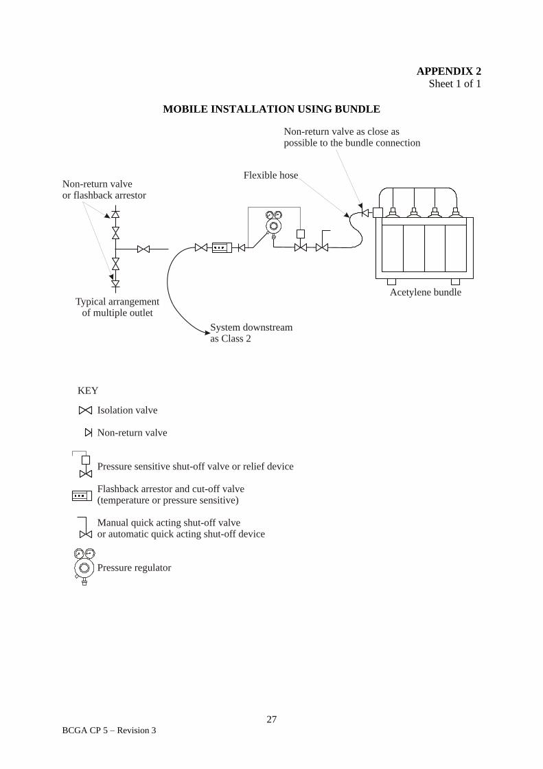
27 BCGA CP 5 – Revision 3
APPENDIX 2
Sheet 1 of 1
MOBILE INSTALLATION USING BUNDLE
KEY
Typical arrangementof multiple outlet
Acetylene bundle
Non-return valve as close aspossible to the bundle connection
System downstreamas Class 2
Isolation valve
Non-return valve
sensitive
Flashback arrestor and cut-off valve(temperature or pressure sensitive)
Pressure shut-off valve or relief device
Manual quick acting shut-off valveor automatic quick acting shut-off device
Pressure regulator
Flexible hoseNon-return valveor flashback arrestor
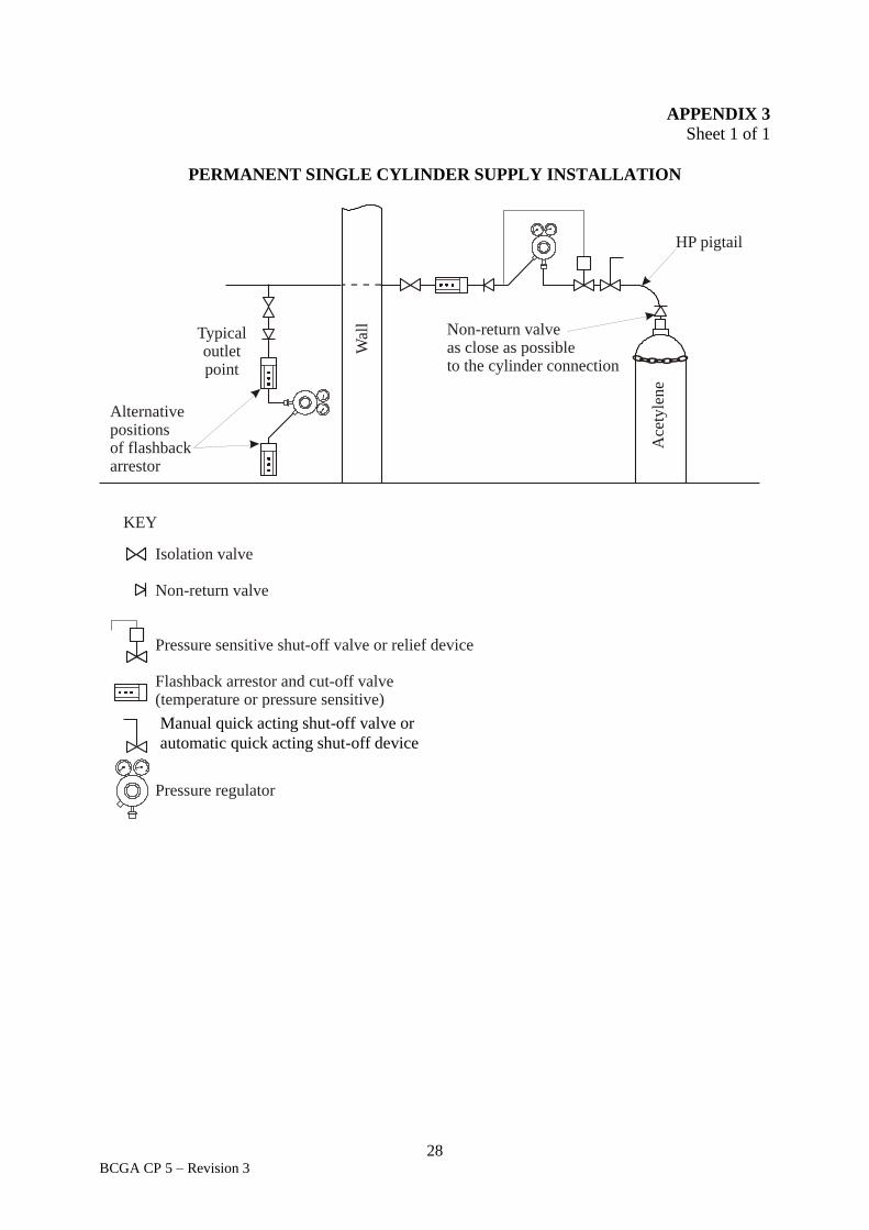
28 BCGA CP 5 – Revision 3
APPENDIX 3
Sheet 1 of 1
PERMANENT SINGLE CYLINDER SUPPLY INSTALLATION
KEY
Typicaloutletpoint
HP pigtail
Ace
tyle
ne
Wal
l
Isolation valve
Non-return valve
arrestor and cut-off valve(temperature or pressure sensitive)
Pressure sensitive shut-off valve or relief device
Flashback
Manual quick acting shut-off valve
Pressure regulator
Non-return valveas close as possibleto the cylinder connection
Alternative positionsof flashback arrestor
Manual quick acting shut-off valve or
automatic quick acting shut-off device
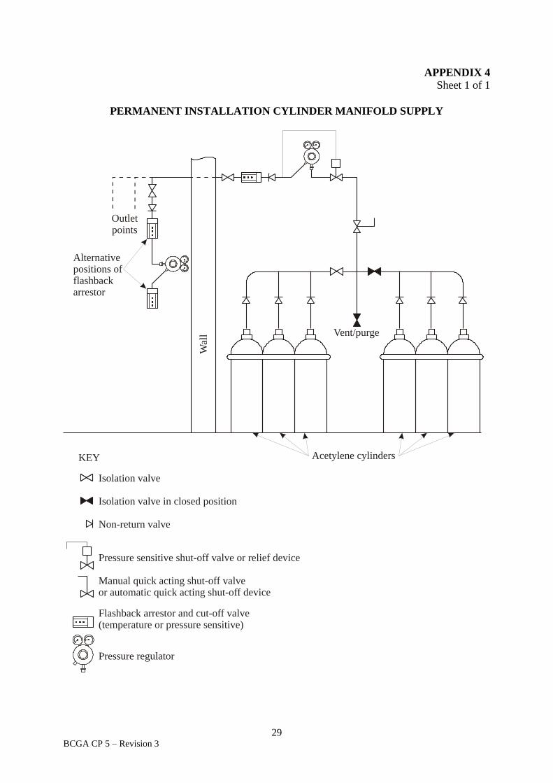
29 BCGA CP 5 – Revision 3
APPENDIX 4
Sheet 1 of 1
PERMANENT INSTALLATION CYLINDER MANIFOLD SUPPLY
Isolation valve
Isolation valve in closed position
Non-return valve
Pressure sensitive shut-off valve or relief device
Manual quick acting shut-off valveor automatic quick acting shut-off device
Flashback arrestor and cut-off valve(temperature or pressure sensitive)
Pressure regulator
KEY
Outletpoints
Acetylene cylinders
Vent/purge
Wal
l
Alternativepositions of flashback arrestor

30 BCGA CP 5 – Revision 3
APPENDIX 5
Sheet 1 of 1
PERMANENT INSTALLATION: BUNDLE MANIFOLD – TYPICAL
ARRANGEMENT
Isolation valve
Isolation valve in closed position
Non-return valve
Pressure senstive shut-off valve or relief device
Pressure regulator
Flashback arrestor and cut-off valve(temperature or pressure sensitive)
Automatic quick acting shut-off device
KEY
Vent/purge
Outletpoints
Pressure sensitveshut-off valve orrelief device
Wal
l
Alternativepositions offlashbackarrestor

British Compressed Gases Association
www.bcga.co.uk