coarse wave-division multiplexing - glen turner · coarse wave-division multiplexing linux.conf.au...
TRANSCRIPT

Coarse wave-division multiplexing
linux.conf.au sysadmin miniconf2013-01-28
Glen Turnerwww.gdt.id.au

Not an ethernet switch

Multiplexing, sharing link bandwidthCombining multiple connections to share one link:– Ethernet uses statistical multiplexing, with data placed in
frames which then queued for transmission onto the link.
– The phone system traditionally works on time-division multiplexing, with each call being allocated a time slot.
– AM radio works on wavelength-division multiplexing, with each channel allocated a frequency.
Can also do wavelength-division multiplexing using optical fibre links.

CWDMCoarse means wide spacing between channels– Less expensive equipment than “dense”, but a smaller
number of channels.
– Price is competitive with ethernet switching
Wavelength division multiplexing– Each signal is assigned a frequency.
– At the transmitter these signals are mixed together.– At the receiver the mixed signal is filtered into its
constituent signals.
Very much a analog technology

CWDM spectral view

SFPs - assigning a frequencySFPs use a wavelength.– 1000Base-LX uses 1310nm.
– 1000Base-ZX uses 1550nm.
CWDM SFPs use wavelengths to fit the CWDM system being used, a different SFP per wavelength– a 8 channel CWDM system will use 1470, 1490, 1510, 1530,
1550, 1570, 1590, 1610.
– to prevent error, SFPs and CWDM mux ports are colour-coded
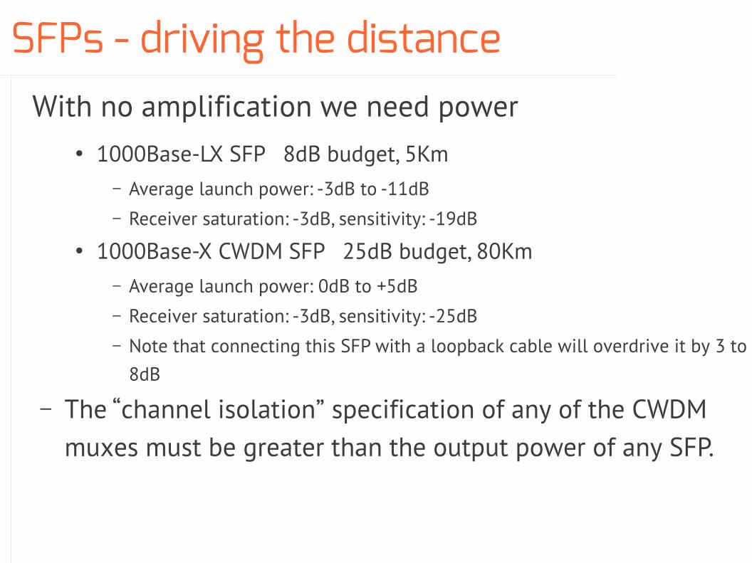
SFPs - driving the distanceWith no amplification we need power
● 1000Base-LX SFP 8dB budget, 5Km– Average launch power: -3dB to -11dB– Receiver saturation: -3dB, sensitivity: -19dB
● 1000Base-X CWDM SFP 25dB budget, 80Km– Average launch power: 0dB to +5dB– Receiver saturation: -3dB, sensitivity: -25dB– Note that connecting this SFP with a loopback cable will overdrive it by 3 to
8dB
– The “channel isolation” specification of any of the CWDM muxes must be greater than the output power of any SFP.

SFPs - bastardrySFPs have a EEPROM to provide information about the unit.
We could checksum that EEPROM and have our switch reject SFPs with checksums it doesn't know about. Locking purchasers of our switch into buying our SFPs, at monopoly prices.

SFPs - anti-bastardryBut EEPROMs are programmable, so let's reverse-engineer the checksum and program them.
We could then provide SFP types that the switch manufacturer does (CWDM, single fibre, etc)

SFPs - bastardry still hurtsBut even so, we still had to fake the parameters in the EEPROM.
So we can't do things like pulling the receiver sensitivity from EEPROM, pulling the received dB from the DOM, and alerting if using the last few dB.

Combiners and splittersCombining light is easy, fuse the fibres together.– with few reflections is harder, but only slightly.
Splitting is easy, once you observe that bending a fibre causes some light leaks out.

Amplification, not in practiceOptical amplifiers work on the same principle as a field effect transistor– A small signal at the gate leads to a cascade of photons from the pump
– This is done by adding elements to the fibre, much as a semiconductor is also “doped”.
– Optical amplifiers might cover one or two bands, and some bands can be amplified at all.
The lack of amplification becomes the practical difference between CWDM and DWDM systems.
If we can't amplify, we must use powerful transmitters, sensitive receivers and highly-isolating filters in the CWDM system.

Changing frequency, not at allThis can easily be done in electronics; it's the basis of FM radios.
There is no non-lab device to change the frequency of light.
So considerable thought is given to allocation of wavelengths.

A multiplexorTransmit– filter and combine signals
Receive– split and filter signals

Simple shared link network

Why?Each user gets full bandwidth– No inter-service QoS
– No inter-service denial of service
Can use differing protocols on differing channels– ethernet, fibre channel, TV, ISDN

Add-drop multiplexorAdd/drop west wavelength, sending it south.
Add/drop east wavelength, sending it north.
W-S E-NIf you want to hurt your brain, consider the individual fibres, rather than the pairs.

Simple chain network
Central site
Chain of branch offices

Why?Efficient use of metro fiber– in our example: 2 cores, not 6 cores
Could chain ethernet switches, but– Further sites vulnerable to power outages at closer sites.
– In-pit muxing can keep shared failure modes out of the site altogether. Useful for schools – they can only access stuff which can cause an outage to themselves.

Redundant chain network
Central site
Chain of branch offices

WhyIf we can make a loop of fibre then we get a fully redundant network.
Note that the movement of traffic from the main to the backup link still requires routing (a switch's spanning tree or MPLS/IP OSPF/BGP).– This is the cheap optical technology, the expensive one will
automatically re-route.
– For switches put this network in its own Multiple Spanning Tree.

Optical fibreFibre optic cable has linear loss and dispersion in only some frequency ranges. These usable frequency ranges are called windows.– When specifying fibre we select models with wide windows
and low loss

Optical fibre windows800 to 900nm Obsolete 1st window
High loss, so not used
1260 to 1490nm Combined Original and Extended bandsNo dispersionE may contain water peak
1460 to 1530nm Short wavelength bandLow loss, some dispersion
1530 to 1565nm Conventional bandLow loss, some dispersionEDFA amplification
1565 to 1625nm Long wavelength bandLow loss, more dispersionEDFA amplification
1625 to 1675nm Ultralong wavelength band

CWDM channels and the water peak
Older fibre has high attenuation at the “water peak” of 1390nm in the E band.
You want to specify “ITU-T G.655” zero water peak, non-zero dispersion-shifted fibre.

CWDM channel planTo allow interoperability systems should use the same frequencies for channels.
The ITU-T G.694.2 band plan:– Lowest channel centred on 1271nm.
– Channels every 20nm.
– Highest channel centred on 1611nm, giving 18 channels.
Not all channels are usable, due to fibre characteristics.
Not all channels can be used by the one system, due to device characteristics.
Only a few channels can be amplified

Power budgetWDM is a analogue system, and can be under- or over-driven– If under-driven, then amplify, but this
typically isn't economic for CWDM
– If over-driven then attenuate.– Attenuators come in 5dB multiples and
work on all wavelengths
– Install attenuation at receiver

Power budget calculationYou want the data sheet for the SFP, the data sheet for the fibre, and the fibre installation test results
From the data sheet for the SFP– Transmitter
● Centre wavelength● (Minimum, typical, maximum) average launch power
– Receiver● (Minimum, centre, maximum) wavelength.● Sensitivity at a bit error rate of 10-12
● Saturation● Dispersion penalty, typically over 100Km

Power budget calculation, cond– From the data sheet for the fibre
● Nominal loss per Km at centre wavelength (0.35dB/Km)
– From the installation tests● Actual loss (typically less than nominal loss, above)
– What is the best case power seen by the receiver?● Maximum transmitter launch power – actual loss
– What is the worst case power seen by the receiver?● Minimum transmitter launch power – nominal loss
– Is the best case power less than the receiver's saturation?
– Is the worst case power greater than the receiver's sensitivity?

Eye safety
CWDM systems use high power, they can scribe a retina or kill rods.– No un-capped fibres.
– Assume all fibre ports are live, never point fibres at people.– Stand in a failsafe place, move after each patch.
– Discourage onlookers.
Do not look into laserwith remaining eye

Fibre capsRemove cap last, restore cap first.
Keep a ziplock bag in each rack for caps.

InstallationA high standard of optical practice is required– system design
– record keeping
– unit testing
– fibre end inspection and cleaning
– patch lead turn radius
This is quite different to practices with site optical ethernet, where huge headroom in the power budget allows some level of poor practice.

Installation – visual fault indicator
A visible laser (650nm)– Discovery of cabling error.
– Use during patching to avoid cabling error.– 1mW laser visible to ~4Km
– A “weapon” (lawful excuse tocarry, must be secured, AVOs)
$100– Cheap ones are fine.

Installation – light meterMeter is calibrated for particular wavelengths.
$450 - $800, for what you are doing, cheap ones are fine.

Installation – light sourceLaser with stable frequency and calibrated output.
$850 - $2,500
For sources and meters look for– The wavelengths you want, at least 1310nm, 1550nm
– Battery and plugpack operation
– Large range of connector adapters (SC, LC, FC, …)
– Australian re-calibration service

Installation – Cletops cleanerFor cleaning fiber optic plugs.– SC and LC spacings
$110

Installation – OneClick cleanerFor cleaning fibre optical sockets and ferrules.– SC (round ferrule) and LC (square ferrule) variants
$90

Fault findingOptical systems are analogue systems at heart.
The style of fault-finding is more like electronics than program debugging:– Attach a meter to a test point.
– Compare that with calculated nominal values and the values recorded during installation.
– Deduce the failure from the observations; or failing that determine which further measurements will discover the hypothesised failures.

Fault finding – loopback cablesPut on during installation, then you aren't always driving to the far end.
Easy way to exclude transmitters and segments from being faulty.

Fault finding - OTDR

Fault finding - OTDR

Fault finding - OTDR continuedYou should request OTDR results for major fibre builds.
The .SOR file format is a BellCore specification, which is not free.
This is a 12Km fibre ending in a CWDM add-drop mux. You can see the launch cable, splices, and the reflection from the mux.

Fault finding - DOMSFPs can measure received light– inaccurate, but good enough to verify power budget
– under the hood uses PHY registers (ref SFF-8472)● these are read and set using a I2C bus● ethtool -D eth0
– can plot using SNMP and thus be alerted to changes

So what are the downsides?Requires dark fibre.
Operational visibility = 0.
Knowledge required is well removed from knowledge of packet networks.
Topology is insufficient– point-to-point links are not as useful as multipoint switched
networks
– In many ways the movement is to connecting hosts to a set of multipoint networks.

Coarse wave-division multiplexing
linux.conf.au sysadmin miniconf2013-01-28
Glen Turnerwww.gdt.id.au
Copyright © Glen Turner of Semaphore, South Australia, 2013.Permission is granted to copy, distribute and/or modify this document under the terms of the GNU Free Documentation License, Version 1.3 or any later version published by the Free Software Foundation; with no Invariant Sections, no Front-Cover Texts, and no Back-Cover Texts.
Thanks to Tony Hisgett <[email protected]> for this cover photo.

but you can use it like oneeg: to share a link between sites