coal gasification pilot plant for … gasification pilot plant for hydrogen production. part b:...
TRANSCRIPT
COAL GASIFICATION PILOT PLANT FOR HYDROGEN PRODUCTION. PART B: SYNGAS CONVERSION
AND HYDROGEN SEPARATION
Giovanni RAGGIO, Alberto PETTINAU *, Alessandro ORSINI, Marcella FADDA SOTACARBO S.p.A.– Società Tecnologie Avanzate Carbone – c/o Centro Servizi C.N.I.S.I. 09010,
Portoscuso (CA), ITALY
Daniele COCCO University of Cagliari – Department of Mechanical Engineering – piazza d’Armi, 09123 Cagliari, ITALY
Paolo DEIANA
ENEA – Centro Ricerche della Casaccia – via Anguillarese 301, 00060 S.Maria di Galeria (RM), ITALY
Maria Luisa PELIZZA, Massimo MARENCO
Ansaldo Ricerche – corso Perrone, 25 – 16152 Genova, ITALY
ABSTRACT Nowadays, the need for a diversification in primary energy sources has raised an
increasing interest in coal, which allows a larger price stability and represents a reliable primary source from a strategic point of view.
Coal gasification processes, in particular, allow an efficient use of this energy source, with a low environmental impact. These processes, moreover, allow hydrogen (and other environmental-friendly fuels) and electric power co-production.
To this effect, Sotacarbo, together with Ansaldo Ricerche, ENEA and the Department of Mechanical Engineering of the University of Cagliari, is developing a pilot plant to test the use of gasification technologies for the combined production of hydrogen and electric power in medium and small scale commercial plants. In particular, the pilot plant is made up of two up-draft fixed-bed gasifiers, respectively 700 and 35 kg/h of coal, the latter equipped with a syngas treatment line, including the depulverization, desulphurization, water-gas shift conversion, CO2 separation and hydrogen purification sections.
This paper reports the main results, achieved by a calculator simulation, of a preliminary analysis carried out to assess the main operating parameters of the advanced syngas conversion process for hydrogen production from coal, which will be tested in the Sotacarbo pilot plant. This process includes a hot syngas desulphurization system, an integrated CO-shift and CO2 removal process, and a hydrogen separation section. In particular, the effects of the main process operating parameters on the performance of each section have been analyzed.
Key-Words: Coal gasification, Sulcis coal, Pilot plant, Hot gas desulphurization, CO-shift,
CO2 removal, Hydrogen production
* Corresponding author: Phone: +39 0781 509047 – Fax: +39 0781 508349 E-mail: [email protected]

NOMENCLATURE ESP Electrostatic Precipitator IGCC Integrated Gasification Combined Cycle LHV Lower Heating Value MDEA Methyl-diethanolamine, (HO-CH2-CH2-)2 N-CH3 MEA Monoethanolamine, HO-CH2-CH2-NH2 PSA Pressure Swing Adsorption WGS Water-Gas Shift conversion process
INTRODUCTION Nowadays, the need to release energy production from the use of oil and natural gas as
primary energy sources and, in general, to diversify such sources in order to assure the supplying, is making coal more and more interesting. This fuel, widely available in the world and distributed more uniformly than oil and natural gas, allows a great price stability and represents a secure source from a strategic point of view [1].
Moreover, the increasing interest in environmental problems has recently led to the development of clean coal technologies, designed to enhance both the efficiency and environmental acceptability of coal extraction, preparation and use, in particular for power generation [2].
Among clean coal technologies, gasification is particularly interesting since it allows both power generation (in Integrated Gasification Combined Cycles power plants, IGCC) and environmental-friendly fuel production, with a particular reference to hydrogen.
All over the world, gasification processes, due to the low flexibility of synthesis gas (syngas) production, are, so far, mainly used in large-scale IGCC power plants in order to supply base energy load. But in a short-term future, the possibility to use syngas to produce hydrogen could make gasification technologies very interesting for medium and small-scale industrial application.
As to this possibility, Sotacarbo, together with Ansaldo Ricerche, ENEA and the Department of Mechanical Engineering of the University of Cagliari, is developing an integrated gasification process for combined production of hydrogen and electrical energy, to be used in medium and small-scale commercial plants. The research project concerns the development of a gasification and syngas treatment pilot plant, which will be located in the Sotacarbo Research Centre at Carbonia, near Cagliari. The plant includes a pilot-scale (700 kg/h) coal gasifier and a laboratory-scale (35 kg/h) coal gasifier; in particular, the latter is equipped with a syngas treatment process for hydrogen production. The research project is co-funded by the Italian Ministry of Education, University and Scientific Research (MIUR) and the total cost is estimated in 11 million euros.
This paper reports the main results of the pilot plant preliminary analysis, based on a computational simulation, and the estimated performances of the main sections of the advanced syngas conversion process for hydrogen production from coal. The analysis of the gasification plant and the conventional cold syngas desulphurization process is reported in the first part of this work [3].
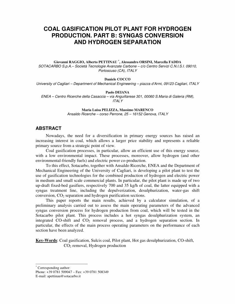
PILOT PLANT CONFIGURATION Sotacarbo and the other partners of the project are currently developing the final design
of the overall pilot plant, which will be used for the R&D activities required by the development and the optimization of the different sections of the integrated process.
In order to test different plant solutions and different operating conditions, during this first phase of the research project a very flexible and simple layout for the pilot plant has been considered. The experimental results obtained by means of this pilot plant will constitute the basis of the second phase of the research project, which will lead to the realization of the demonstrative unit of the Sotacarbo coal-to-hydrogen process.
The currently layout of the Sotacarbo pilot plant includes two fixed-bed up-draft Wellman-Galusha gasifiers: a 700 kg/h pilot gasifier and a 35 kg/h laboratory-scale gasifier; both gasifiers are equipped with a wet scrubber for syngas cooling (to about 50 °C) and dust and tar removal. In particular, the 35 kg/h laboratory-scale gasifier will be equipped with the overall syngas treatment process, in order to produce the hydrogen for the power generation section.
Figure 1 shows the simplified scheme of the Sotacarbo laboratory-scale coal gasification plant. As mentioned, the coal gasification section includes the gasifier and the wet scrubber, as well as a wet electrostatic precipitator (ESP), which allows to achieve a fine particulate and tar removal. The clean gas leaves the ESP at atmospheric pressure and, by means of a compressor which increases the pressure to about 1.4 bar, feeds the downstream syngas conversion section.
heater N2
cold gasdesulphurization
hot gasdesulphurization
coal
ash
air
O2 for air enrichment
steam
coalpreparation
gasifier(35 kg/h)
wetscrubber
ESP
syngas
high temp.WGS
low temp.WGS
CO2removal
CO2removal
H2
H2 purification
H2 for syngasenrichment
dieselengine
H2-richsyngas
CO2 stream
flare
ash
water
water heater N2
cold gasdesulphurization
hot gasdesulphurization
coal
ash
air
O2 for air enrichment
steam
coalpreparation
gasifier(35 kg/h)
wetscrubber
ESP
syngas
high temp.WGS
low temp.WGS
CO2removal
CO2removal
H2
H2 purification
H2 for syngasenrichment
dieselengine
H2-richsyngas
CO2 stream
flare
ash
water
water
Figure 1 – Simplified scheme of the Sotacarbo laboratory-scale experimental plant.
According to the design conditions, downstream the compressor, the syngas is splitted
into two streams: the main stream, about 80% of the produced syngas, is sent to a cold gas desulphurization process, whereas the secondary stream, that is the remaining 20% of the produced syngas, is sent to a hot gas desulphurization process, which is followed by the hydrogen production section. In particular, the cold gas desulphurization process is based on a
hydrogen sulphide (H2S) absorption process (which uses MDEA as sorbent) and it is directly followed by the power generation section, represented by an internal combustion engine (diesel cycle). The secondary syngas treatment line includes a dry hot gas desulphurization process (which employs metal oxide-based sorbents) followed by an integrated CO-shift and CO2 absorption system and a hydrogen purification system, based on the PSA (Pressure Swing Adsorption) technology. The size of the secondary syngas treatment line, even if much smaller than the size of commercial scale plants, should give reliable experimental data for the scale-up of the future plants.
The laboratory-scale gasifier is designed to operate with enriched air (simply by using an oxygen tank). Moreover, the possibility to test the internal combustion engine with hydrogen enriched fuels has been considered. In order to produce hydrogen enriched fuels, the hydrogen produced by the hot gas treatment line can be mixed with the clean syngas from the cold gas desulphurization process; otherwise, it is possible to operate the hydrogen enrichment simply by using a hydrogen tank located upstream the diesel engine.
Furthermore, a suitable portion of the clean syngas produced by the cold desulphurization process can be splitted upstream the diesel engine and fed to the integrated CO-shift and CO2 absorption system, in order to compare the performances of both cold and hot syngas desulphurization processes for hydrogen production.
In order to ensure a full plant flexibility, as well as to simplify the management of the experimental pilot plant, the different cooling and heating devices are not fully integrated. However, the aforementioned layout, if necessary, can be easily modified without significant costs.
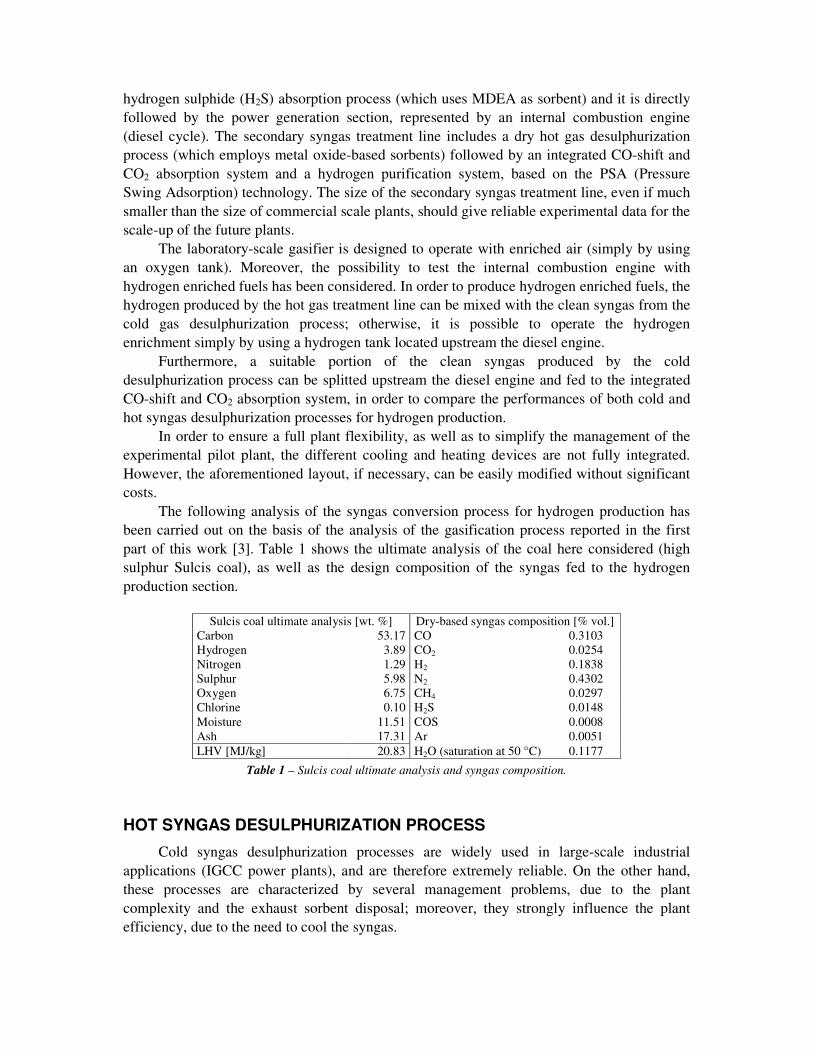
The following analysis of the syngas conversion process for hydrogen production has been carried out on the basis of the analysis of the gasification process reported in the first part of this work [3]. Table 1 shows the ultimate analysis of the coal here considered (high sulphur Sulcis coal), as well as the design composition of the syngas fed to the hydrogen production section.
Sulcis coal ultimate analysis [wt. %] Dry-based syngas composition [% vol.]
Carbon 53.17 CO 0.3103 Hydrogen 3.89 CO2 0.0254 Nitrogen 1.29 H2 0.1838 Sulphur 5.98 N2 0.4302 Oxygen 6.75 CH4 0.0297 Chlorine 0.10 H2S 0.0148 Moisture 11.51 COS 0.0008 Ash 17.31 Ar 0.0051 LHV [MJ/kg] 20.83 H2O (saturation at 50 °C) 0.1177
Table 1 – Sulcis coal ultimate analysis and syngas composition.
HOT SYNGAS DESULPHURIZATION PROCESS Cold syngas desulphurization processes are widely used in large-scale industrial
applications (IGCC power plants), and are therefore extremely reliable. On the other hand, these processes are characterized by several management problems, due to the plant complexity and the exhaust sorbent disposal; moreover, they strongly influence the plant efficiency, due to the need to cool the syngas.

Therefore, in order to develop a small-scale commercial plant (where global efficiency plays an important role), a hot gas desulphurization process (figure 2) will also be tested in the Sotacarbo pilot plant; in fact, even if these processes are still far from a massive industrial application, they are extremely simple in their plant configuration and management; moreover, hot syngas desulphurization processes allow to improve the efficiency of the coal gasification plant due to the absence of a deep syngas cooling process.
raw syngas
clean syngas
reactor 1(absorption)
heater
reactor 2(desorption)
air
acid gasraw syngas
clean syngas
reactor 1(absorption)
heater
reactor 2(desorption)
air
acid gas
Figure 2 – Simplified scheme of the hot syngas desulphurization process.
In the Sotacarbo laboratory-scale plant, about 20% of the syngas produced by the
gasification and depulverization sections is heated to about 350 °C and sent to the desulphurization system. The latter includes two identical reactors, since when one reactor operates as absorber, the other is regenerated.
The absorption of sulphur compounds (H2S and COS) takes place at about 350 °C. The two fixed-bed reactors are filled up with an iron oxide (Fe3O4) based sorbent, which operates the sulphur compound absorption according to the following reactions:
),(33),(3 2222243 COOHOHFeSCOHSHOFe ++!++ ),(33),(3 222243 COOHCOFeSCOHCOSOFe ++!++
The two reactors will be designed in order to obtain a final sulphur compound
concentration lower than 100 ppm, since the desulphurized stream is subsequently sent to the CO-shift process.
As the reaction progresses, the iron oxide is progressively converted into FeS, decreasing the absorption efficiency. When the final concentration of sulphur compounds exceeds the limit value of 100 ppm, the absorber reactor is switched to the regeneration phase, and the syngas is fed to the other reactor.
Sorbent regeneration takes place by sending atmospheric air into the saturated reactor in order to promote the following exothermic ("H = -2470,28 kJ/mol) reaction:
2322 4274 SOOFeOFeS +!+
At the same time, the un-reacted iron oxide reacts with the air oxygen according to the
following reaction:

32243 64 OFeOOFe !+
Finally, the Fe2O3 produced by the two previous reactions, is reduced to Fe3O4 by
reacting with H2 and CO according to the following reaction:
),(2),(3 2243232 COOHOFeCOHOFe +!+ The SO2-rich flow is sent to the same acid gas treatment system used for the cold gas
desulphurization process, where the SO2 is directly converted to H2SO4, without the need of the preliminary combustor [4-5-6].
Even if a number of papers on hot gas desulphurization processes are available in the scientific literature, it is important to notice that it is very difficult to find reliable data for a detailed plant design. Therefore, Sotacarbo, together with the University of Cagliari, is conducting some preliminary tests on different metal oxides, in order to accurately define the main absorption performances and the optimal operating conditions of such sorbents.
INTEGRATED WATER GAS SHIFT AND CO2 REMOVAL PROCESS
In order to produce a hydrogen-rich fuel, water-gas shift conversion integrated with a CO2 removal process (see figure 3) has been selected. At the design conditions, the integrated process is fed by the syngas exiting from the hot gas desulphurization process; however, this process can also be fed by a portion of the syngas treated by the cold gas desulphurization process (fig. 1).
In particular, the syngas enrichment in hydrogen is carried out by using a double catalytic stage CO-shift process, with an intermediate carbon dioxide absorption stage and a final CO2 removal process.
clean syngas
CO-shift(1st stage)
CO-shift(2nd stage)
hydrogen rich syngas
CO2 removal(intermediate stage)
CO2 removal(final stage)
clean syngas
CO-shift(1st stage)
CO-shift(2nd stage)
hydrogen rich syngas
CO2 removal(intermediate stage)
CO2 removal(final stage)
Figure 3 – Integrated water-gas shift conversion and CO2 removal system.
This integrated configuration has been selected in order to maximize the carbon
monoxide conversion into CO2, for a future use of the hydrogen-rich fuel in a high efficiency power generation section (based on fuel cells).

The two CO2 removal stages carry out an absorption of carbon dioxide with a solution of water and monoethanolamine (MEA) at an operating temperature of about 30 °C. In order to minimize the steam consumption and optimize thermal exchanges in the integrated process, only a portion of syngas from the first CO-shift stage is sent to the intermediate CO2 absorption section. In particular, the mass flow of this stream is designed to reduce the final syngas temperature from about 400 °C to 250 °C (that is operating temperature in the second CO-shift stage) by mixing syngas from intermediate CO2 absorber (at 30 °C and in saturation conditions) and the remaining syngas (at about 400 °C) coming directly from the first CO-shift stage.
At design conditions, about 68% of the syngas exiting from the first CO-shift reactor must be sent to the intermediate CO2 absorption process. However, as shown by Figure 4 the use of enriched air leads to a decrease of the syngas mass flow sent to the intermediate CO2 separation stage.
0 0.2 0.4 0.6 0.8 1Oxygen purity (%vol)
0.4
0.5
0.6
0.7
0.8
Inte
rmed
iate
CO
2 rem
oval
mas
s ra
tio
Figure 4 – Stream to intermediate CO2 absorption stage (as fraction of stream from CO-shift 1st stage).
Equilibrium analysis of double-stage water-gas shift conversion As already mentioned, the desulphurized syngas is sent to a CO-shift conversion
process, where the following catalytic reaction is promoted:
222 HCOOHCO +!+ As this chemical reaction is exothermic ("H = -41.165 kJ/mol), it is favoured by low
temperatures; on the other hand, by reducing the temperature, the catalyst activity decreases, with a consequent reduction of the reaction rate. Therefore, according to the commercial CO-shift systems (widely used in petrochemical industry), the process is based on a series of two catalytic reactors: the first, operating at high temperatures (about 350÷400 °C), converts a large portion of carbon monoxide into hydrogen and CO2, taking advantage from the high

reaction rate; the second, which operates at low temperature (about 250 °C), refines the carbon monoxide conversion, thus allowing to achieve low CO final concentrations (lower than 1% in volume).
In order to allow the CO-shift reaction, the syngas fed to the first CO-shift stage is mixed with steam. Obviously, by increasing the steam/CO molar ratio, the chemical equilibrium shifts towards the reaction products. In particular, figure 5 shows the trend of carbon monoxide conversion (in each of the two single stages and in the overall process) by varying this molar ratio. The analysis has been carried out under the assumption of chemical equilibrium, with reference to the design conditions reported in table 2 and by using the Aspen Plus 12.1 simulation software [7].
CO-shift operating conditions
1st stage temperature [°C] 350÷400 2nd stage temperature [°C] 250 Pressure [bar] 1.01 Steam/CO molar ratio (design condition) 2.5
Syngas feeding properties Mass flow [kg/h] 21.518 Temperature [°C] 350 Pressure [bar] 1.01
Syngas feeding composition CO 0.2762 CO2 0.0226 H2 0.1636 N2 0.3829 H2O 0.1238 CH4 0.0264 H2S traces COS traces Ar 0.0045
Table 2 – CO-shift process: main operating conditions.
0 1 2 3 4 5Steam/CO molar ratio
0
0.2
0.4
0.6
0.8
1
CO
con
vers
ion
1st stage
2nd stage
Overall process
Figure 5 – Equilibrium conversion of the CO-shift process.

Figure 5 shows that, according to the design conditions, the assumption of a steam/CO
molar ratio equal to 2.5 represents a good compromise between conversion efficiency and reactor size.
Amine-based CO2 absorption process
At the Sotacarbo pilot plant will be tested an innovative amine-based carbon dioxide absorption process, which is currently under development by Ansaldo Ricerche. Conceptually, this is very similar to the conventional processes, with some improvements in order to optimize heat exchanges and separation efficiency.
As already mentioned, the pilot plant is equipped with a two stage CO2 removal process: an intermediate stage, fed with a portion of the shifted syngas, and a final stage, fed with all the syngas from the last CO-shift reactor. Both processes use a mixture of water and monoethanolamine (MEA, which has molecular formula HO-CH2-CH2-NH2) as sorbent. The conceptual scheme of each process is shown in figure 6.
feed syngas
treated syngas
absorber
separated CO2
stripper
sorbent make-up
liquid-liquidheat exchanger
feed syngas
treated syngas
absorber
separated CO2
stripper
sorbent make-up
liquid-liquidheat exchanger
Figure 6 – Conceptual scheme of conventional amine-based CO2 absorption process. The absorption process is mainly ruled by the following overall reaction [8]:
#+ +!+ NHCOOCHHOCHNHCHHOCHNHCHHOCHCO 223222222 2 This reaction takes place in two steps:
+# +!+ HNHCOOCHHOCHNHCHHOCHCO 222222 ++ !+ 322222 NHCHHOCHNHCHHOCHH
These reactions are highly influenced by absorption temperature and pressure and by pH value in the solvent solution (which depends on amine concentration). In particular, the process operates at 30 °C and about atmospheric pressure.
Saturated sorbent from both absorbers (which are characterized by the same operating conditions) is sent to the stripping column at about 90 °C. In this column, the reverse reactions take place, and the saturated sorbent release the carbon dioxide. The water and the sorbent vapours entrained in the released CO2, are separated by a condenser, so as to reduce the sorbent make-up.
The preliminary analysis of the CO2 separation process has been carried out by using the ChemCAD 5.2 simulation software [9]. In particular, syngas from the second CO-shift stage is cooled to about 30 °C (with the condensation of steam) and subsequently sent to the
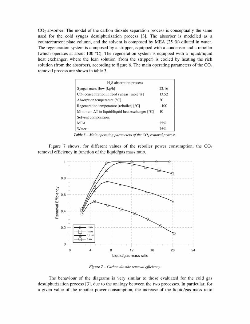
CO2 absorber. The model of the carbon dioxide separation process is conceptually the same used for the cold syngas desulphurization process [3]. The absorber is modelled as a countercurrent plate column, and the solvent is composed by MEA (25 %) diluted in water. The regeneration system is composed by a stripper, equipped with a condenser and a reboiler (which operates at about 100 °C). The regeneration system is equipped with a liquid/liquid heat exchanger, where the lean solution (from the stripper) is cooled by heating the rich solution (from the absorber), according to figure 6. The main operating parameters of the CO2 removal process are shown in table 3.
H2S absorption process
Syngas mass flow [kg/h] 22.16 CO2 concentration in feed syngas [mole %] 13.52 Absorption temperature [°C] 30 Regeneration temperature (reboiler) [°C] ~100 Minimum !T in liquid/liquid heat exchanger [°C] 10 Solvent composition: MEA Water
25% 75%
Table 3 – Main operating parameters of the CO2 removal process. Figure 7 shows, for different values of the reboiler power consumption, the CO2
removal efficiency in function of the liquid/gas mass ratio.
0 4 8 12 16 20 24Liquid/gas mass ratio
0
0.2
0.4
0.6
0.8
1
Rem
oval
Effi
cien
cy
15 kW
10 kW
7,5 kW
5 kW
Figure 7 – Carbon dioxide removal efficiency. The behaviour of the diagrams is very similar to those evaluated for the cold gas
desulphurization process [3], due to the analogy between the two processes. In particular, for a given value of the reboiler power consumption, the increase of the liquid/gas mass ratio
involves an increase of the absorption efficiency, until a maximum value. As a matter of fact, for a given power consumption, by increasing the liquid mass flow a reduction of the stripping gas flow (and then of the regeneration temperature) takes place, with a consequently pH reduction in the lean solution and a decrease of the CO2 separation efficiency.
On the other hand, an increase of the stripper power consumption involves an increase of the removal efficiency. In particular, in order to achieve a CO2 removal efficiency higher than 95%, a power consumption higher than about 10 kW and a liquid/gas mass ratio higher than of about 8 are required.
HYDROGEN SEPARATION SYSTEM In order to assess the capabilities of the pilot plant to produce a hydrogen-rich fuel for
fuelling advanced power generation systems (as micro gas turbines and fuel cells), the Sotacarbo pilot plant will be equipped with an hydrogen purification system. In particular, a PSA (Pressure Swing Adsorption) system will be selected for the current plant configuration, but other kind of processes will be considered for the plant scale-up.
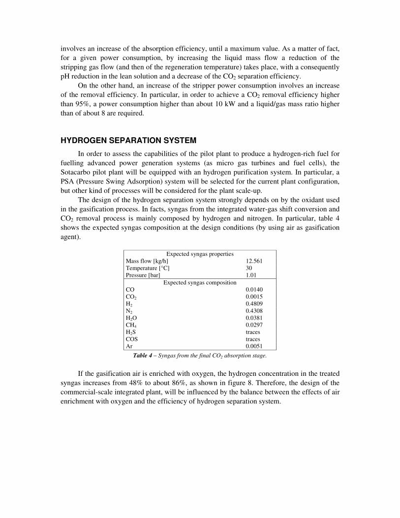
The design of the hydrogen separation system strongly depends on by the oxidant used in the gasification process. In facts, syngas from the integrated water-gas shift conversion and CO2 removal process is mainly composed by hydrogen and nitrogen. In particular, table 4 shows the expected syngas composition at the design conditions (by using air as gasification agent).
Expected syngas properties
Mass flow [kg/h] 12.561 Temperature [°C] 30 Pressure [bar] 1.01
Expected syngas composition CO 0.0140 CO2 0.0015 H2 0.4809 N2 0.4308 H2O 0.0381 CH4 0.0297 H2S traces COS traces Ar 0.0051
Table 4 – Syngas from the final CO2 absorption stage. If the gasification air is enriched with oxygen, the hydrogen concentration in the treated
syngas increases from 48% to about 86%, as shown in figure 8. Therefore, the design of the commercial-scale integrated plant, will be influenced by the balance between the effects of air enrichment with oxygen and the efficiency of hydrogen separation system.

0 0.2 0.4 0.6 0.8 1Oxygen purity (%vol)
0
0.2
0.4
0.6
0.8
1
Fina
l con
cent
ratio
n
H2
N2
Figure 8 – Hydrogen and nitrogen concentration in treated syngas.
CONCLUSIONS Sotacarbo, together with Ansaldo Ricerche, ENEA and the Department of Mechanical
Engineering of the University of Cagliari, is developing an integrated gasification process for co-production of hydrogen and electrical energy for medium and small-scale commercial applications. The research project, funded by the Italian Ministry of Instruction, University and Scientific Research, concerns the development of a gasification and syngas treatment pilot plant, which will be located in the Sotacarbo Research Centre at Carbonia, near Cagliari.
The pilot plant, which will be composed by two gasification sections (a pilot 700 kg/h gasifier and a laboratory-scale 35 kg/h gasifier) includes an advanced syngas treatment line for hydrogen production, composed by a hot syngas desulphurization process, an integrated CO-shift and CO2 removal system and a hydrogen purification section.
The preliminary analysis (carried out with reference to Sulcis coal), whose main results are reported in this paper, allowed to emphasize the main operating parameters of the syngas treatment processes, in particular CO-shift and CO2 separation.
As to the water-gas shift conversion process, the most significant parameter is the steam/CO molar ratio. In particular, the study demonstrates that a steam/CO molar ratio equal to 2.5 is enough to achieve an almost complete CO conversion.
As regards the amine-based CO2 removal system, the carbon dioxide absorption efficiency is strongly conditioned by the liquid/gas mass ratio and by the reboiler power consumption. In particular, in order to achieve a CO2 removal efficiency higher than 95%, a power consumption higher than about 10 kW and a liquid/gas mass ratio higher than of about 8 are required.
Finally, the analysis shows that, if the gasification air is enriched with oxygen, the hydrogen concentration in the treated syngas increases from 48% to about 86%. This effect

strongly influences the design of the hydrogen separation system and requires a careful optimization of the integrated commercial-scale plant.
ACKNOWLEDGMENTS The authors are very grateful to Mr. Carlo Amorino and to Prof. Giorgio Cau for the
useful suggestions provided during this work.
REFERENCES [1] U.S. Department of Energy, Annual Energy Outlook 2004, available at
www.eia.doe.gov/oiaf/aeo/, January 2004. [2] S. Wadhwani, A.K. Wadhwani, R.B. Agarwal, Clean coal technologies – recent
advances, First International Conference on Clean Coal Technologies for Our Future, Chia Laguna, Sardinia, Italy, 21-23 October 2002.
[3] G. Raggio, A. Pettinau, A. Orsini, M. Fadda, D. Cocco, P. Deiana, M.L. Pelizza, M. Marenco, Coal gasification pilot plant for hydrogen production. Part A: coal gasification and syngas desulphurization, Second International Conference on Clean Coal Technologies for Our Future, Castiadas, Sardinia, Italy, 10-12 May 2005.
[4] K. Thambimuthu, Gas cleaning for advanced coal-based power generation, IEA Coal Research, IEACR/53, 1993.
[5] S.C. Mitchell, Hot gas cleanup of sulphur, nitrogen, minor and trace elements, IEA Coal Research, the Clean Coal Centre, CCC/12, 1998.
[6] H. Hederer, Dry sulphur removal for combined cycles coal gasification, Battelle report No. 89FGC-1, Battelle Columbus Laboratories, Columbus, Ohio, 1990.
[7] Aspen Technology, Inc., Aspen Plus Reference Guide, 1996. [8] H. Hikita, S. Asai, H. Ishikawa, M. Honda, The kinetics of reactions of carbon dioxide
with monoethanolamine, diethanolamine and triethanolamine by a rapid mixing method, The Chemical Engineering Journal, vol. 13, 1997, p. 7-12.
[9] Chemstation, Inc., ChemCAD, Version 5.2, User Guide and Tutorial, Houston, Texas, USA, 2002.