co2 transport demonstration · current update on co2 capture and transport study in sustainable ccs...
TRANSCRIPT
1
Current update on CO2 capture and transport study in Sustainable CCS Project by the Ministry of Environment Japan
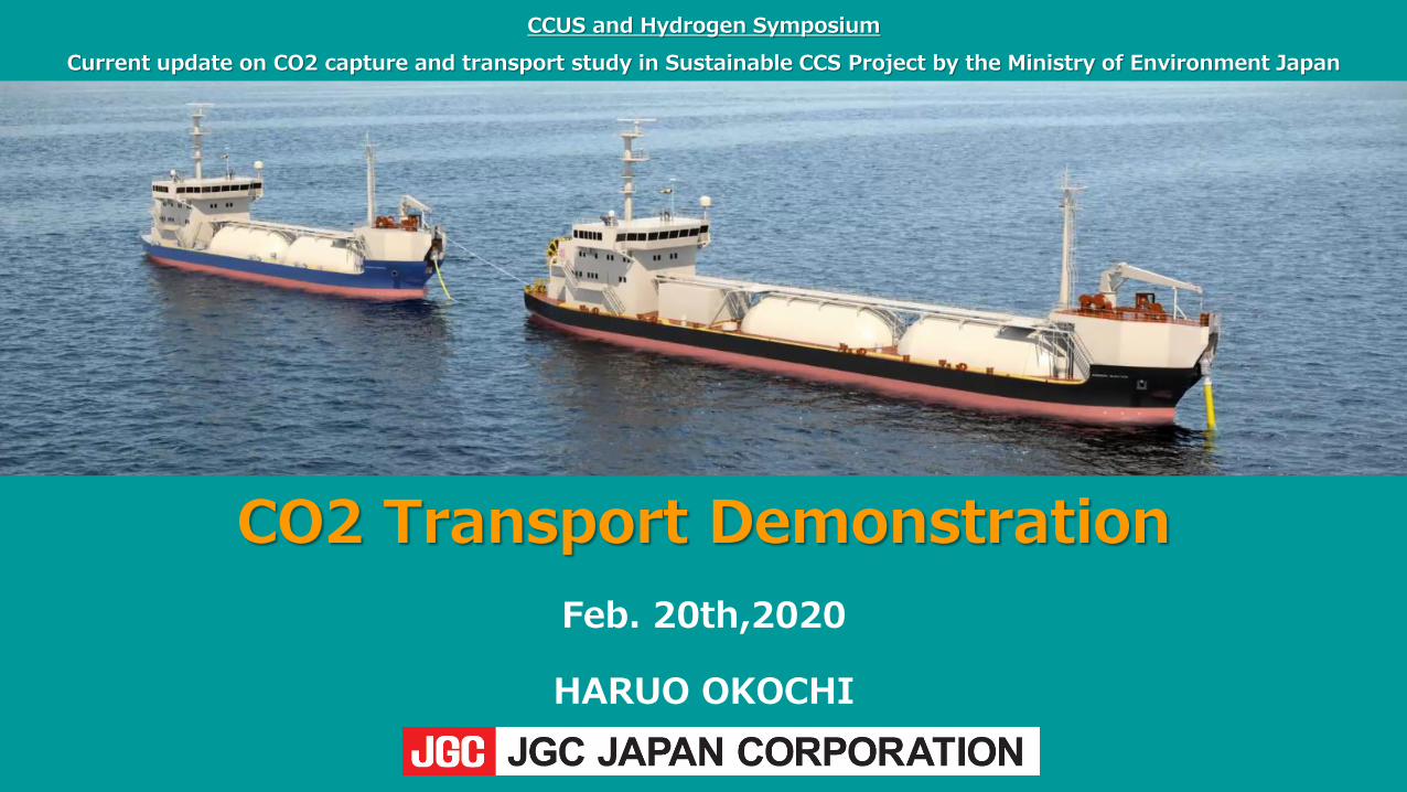
CO2 Transport DemonstrationFeb. 20th,2020
HARUO OKOCHI
CCUS and Hydrogen Symposium

2
AGENDA
1. Sustainable CCS Project by MOE_____________________________3
2. CO2 transport____________________________________________5
3. Significance of CO2 Ship Transport___________________________6
4. Features of Ship Transport ______________________________7
5. CCS Integrated System for Offshore Storage Sites_____________8
6. Transport Scenario Study_________________________________11
7. Summary______________________________________________16
8. Target and Prospects___________________________________17

3 3
The project demonstrates the capturing of the most of the emitted CO2 at an existing coal power plant. It also identifies a smooth deployment methodology by taking the demo results into consideration.
CCS project overview
TransportUyeno TranstechJGC JAPAN Corp.Chiyoda Corp.University of TokyoTaisei Corp.
* Officially launched in FY2018
Consideration of CO2 transport method suitable for Japanese condition
Storage (Monitoring etc.)
Mitsubishi MaterialsTaisei Corp.CRIEPIINPEXMitsubishi Corporation Exploration
JANUSAISTUniversity of TokyoDIA ConsultantKyushu University
Storage planning for the candidate sites, following the suitable site identification
Monitoring planning for the candidate sites, following the suitable site identification
Developing a smooth deployment methodology of CCSQJ ScienceJANUSMizuho Information & Research InstituteKyushu University
Taiheiyo CementJCOAL
- Examination and assessment of CCS deployment path- Assessment of the relevant technologies via working groups and expert interviews
- Organizing an international symposium etc.
Separation and captureToshiba Energy Systems & SolutionsMizuho Information & Research Institute
Evaluating the operation of the thermal power plant with large-scale CO2 capturing plant etc.
CO2 capture: 500tCO2/day
Illustrative
1. Sustainable CCS Project by MOE
4 4
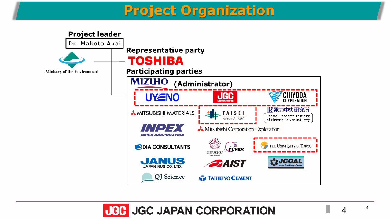
Project Organization

5Japan CCS Forum 2019
2. CO2 Transport
Standard Condition(Gas)2.0 kg/m3(0℃, 1 bar)
Liquefaction(Liquid) 1,030 kg/m3(-20℃, 20 bar)
The volume of CO2 is reduced to about 1/550 by liquefaction
Image of CCS※①~③: Ship transport case
①CO2 Capture
CO2 Emission Source
Capture
Transport
Storage
Injection from onshoreinto onshore reservoir
Injection from onshoreinto subsea reservoir Injection from offshore
into subsea reservoir
③Injection from shipinto subsea reservoir
② Ship Transport
Pipeline
Pipeline
CO2 reservoir
Onshore Aquifer Impermeable layer
SOURCE: English translation of Ministry of Environment Japan’s material
CCS Flow Need to transport the CO2 captured from CO2 emission sources
Select transport methods considering the locational relationship between CO2 emission sources and storage sites, existing infrastructures and transport capacity, etc.
Onshore transport ;Pipeline, Tank Lorry (truck) and Railway
Offshore transport ;Ship transport, Subsea Pipe line
CO2 physical property at transport;Gas, Liquid, Solid
In offshore ship transport, higher transport efficiency by the volume reduction with compression and liquefaction
CO2 reservoir
Subsea

6Japan CCS Forum 2019
3. Significance of CO2 Ship Transport When CCS acts as a tool for GHG reduction, it is necessary to identify
reservoirs with sufficient to stably storage CO2 together with efforts toreduce the generation of CO2 itself and effectively utilize generated CO2.
However in Japan, the storage potential for CO2 is small on land, while it islarge in the surrounding sea area. In addition, most major CO2emission sources are located in coastal areas. Therefore, fromtransportability point of view, CO2 storage in sea areas areconsidered as a reasonable option.
When the storage site is offshore far from CO2 emission sources, a series of system of CO2 liquefaction, CO2 ship transport and CO2 on-board injection is required.
A series of CCS systems from transport to injection (CCS integrated system) has not been proven in Japan. Therefore, Demonstration Testing at practical scale needs to be conducted from the viewpoint of establishing technical feasibility, safety and economy before reaching the commercial stage in the future.
Under the Basic Energy Plan, etc., research and development aimed at commercializing CCUS technology in around 2020 are being promoted, and for that purpose, it is necessary to urgently establish CO2 maritime transportation technology.
Location distribution ofthermal power plants in Japan
7Japan CCS Forum 2019
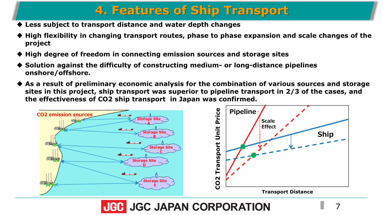
4. Features of Ship Transport Less subject to transport distance and water depth changes
High flexibility in changing transport routes, phase to phase expansion and scale changes of the project
High degree of freedom in connecting emission sources and storage sites
Solution against the difficulty of constructing medium- or long-distance pipelines onshore/offshore.
As a result of preliminary economic analysis for the combination of various sources and storage sites in this project, ship transport was superior to pipeline transport in 2/3 of the cases, and the effectiveness of CO2 ship transport in Japan was confirmed.
PipelineScaleEffect
Ship
Transport Distance
CO
2 T
ran
spor
t U
nit
Pri
ce
Storage SiteB
Storage SiteD
Storage SiteC
CO2 emission sources
Storage SiteE
Storage SiteA

8Japan CCS Forum 2019
5. CCS Integrated System for Offshore Storage Sites(1) CO2 Ship Transport and Injection System
Example of Technical Option forCO2 Ship Transport and Injection System

9Japan CCS Forum 2019
5. CCS Integrated System for Offshore Storage Sites(2) Overview of Main Facilities and Equipment
CO2 Injection Ship
CO2 Transport ShipCO2 Loading at PortCompression, Liquefaction and Storage
CO2 Injection Ship
FRPMooring Rope
Turn Table

10Japan CCS Forum 2019
5. CCS Integrated System for Offshore Storage Sites(3) Steps for establishing CCS Integrated System
Fiscal 2016 2017 2018 2019 2020
Study for technical issues related toCO2 transport and countermeasures
Study for the combination of sources & sinks and selection of the candidate transport models
Confirming prospect of technical feasibility of each component technology
Economic analysis of optimal transport method considering the combination of various emission sources & storage sites
Screening of Scenarios
Basic Concept for Demonstration of CCS
integrated system
Transport model concept for future commercial phase
Transport model rationalization and countermeasure proposal
Comparative study of multiple transport
scenarios
Concretizing the demonstration test plan
◆Various Options・Onshore capacity・Transport capacity・Transport distance・Sea depth at storage site・Port conditions・Injection/mooring
methods
・Optimization of whole system
・Screening of technical options
・Cost reduction
Study and demonstration on component and elemental technology applicable to commercial phase
Study for the future commercial phase

11
6. Transport Scenario Study(1) Multiple Transport Scenarios
Facilities/Locations Onshore Facilities(Compression, Liquefactionand Storage)
Port facilities Transport/Injection Ship Storage Site Location
Typical Variable Factors (Parameters)
Installation Capacity Pier Location Cargo Tank Capacity ・Marine Transport Distance・Sea Depth・Marine/Weather Conditions
Options Maximum (600tCO2/day)
Minimum (<600tCO2/day)
◆Pier 1(※)
◆Pier 2(※)
◆Pier 3(※)
1,500t〜3,000 tCO2/vessel
900 tCO2/vessel
Available Ship Size dependson conditions of each pier.
◆ Storage Site A(※)
◆ Storage Site B(※)
◆ Storage Site C(※)
◆Define representative multiple transport scenarios (13 cases) considering the combination of options
◆Cost Estimate of each transport scenario
(※)Candidate Location
Variations
12
◆For the pier, using “pier-1” rather than “pier -3” can increase the size of the transport vessel and increase the total amount of injection, but pier 1 is expensive to remove the existing facilities and build a new pier.
➡ Reduce cost by modifying and reusing the existing pier-1
◆The capacity of onshore facilities is more reasonable in terms of cost if it is matched to the transportable amount.
➡The capacity of onshore facilities will be determined in consideration of transport and injection efficiency (= total amount of CO2 injection÷total amount of liquefied CO2 production) to optimize the overall cost.
[Ship capacity x transport distance ⇒ transportable capacity ⇒ onshore facilities capacity]
◆The shorter the transport distance and the larger the ship transport capacity, the greater the total CO2 injection can be.
➡ Maximize total CO2 injection amount by increasing ship capacity within an acceptable budget range
◆The proportion of ship costs for transport and injection ships of total cost is large.
➡ Pursue improvement measures to reduce ship costs
6. Transport Scenario Study(2) Improvement Points for Cost Reduction

13
Construction cost composition ratio (Storage Site A, Transport Distance:〜1,300km)
Ship Cost
Pier-1
Ship Cost
Pier-1Ship Cost
Ship Cost
6. Transport Scenario Study(3) Cost Analysis(1/2)
Case 1・Onshore Capacity:600tCO2/d・Pier:Pier-1・Transport Ship:1,500tCO2/vessel
Case 3・Onshore Capacity:600tCO2/d・Pier:Pier-3・Transport Ship:900tCO2/vessel
Case 4・Onshore Capacity:120tCO2/d・Pier:Pier-3・Transport Ship:900tCO2/vessel
Case 2・Onshore Capacity:200tCO2/d・Pier:Pier-1・Transport Ship:1,500tCO2/vessel

14
Construction Cost vs CO2 Injection Amount
Storage Site C
Transport Distance:〜500km
Sea Depth:200m(Assumed)
6. Transport Scenario Study(3) Cost Analysis(2/2)
The capacity of onshore facility is optimized in accordance with transport capacity.

15
Screening an advantageous transportation scenario for each storage site from theviewpoints of transport and injection efficiency, cost, and energy efficiency consideringimprovement points
Next Steps for Optimization of Transport System by Quantitative Indexes(Under evaluation at present)
① Index of Transport and Injection efficiencies (-)Annual CO2 Injection Amount (tCO2/y)÷ Liquefied CO2 Production Amount(tCO2/y at Liquefaction Plant)This index includes all efficiencies such as transportation efficiency, berthing time at the port, Shipto Ship transportation time, and injection time. If the liquefaction facility produces liquefied CO2that exceeds transportable amount, this index will be small, and the utilization rate will be poor.
② Index of Cost (JPY/tCO2)Lifetime cost of the facilities from liquefaction to Injection (JPY)÷Total injected CO2 for plant life (tCO2)
Lifetime cost includes OPEX during whole operation period as well as CAPEX.
③ Index of Energy Efficiency (kWh/tCO2)Annual Power Consumption(kWh/y)÷Annual CO2 Injection Amount (tCO2/y)For example, in case of liquefaction facility, this index represents consumed energy (electric power)per the amount of CO2 processed.

16Japan CCS Forum 2019
The CCS integrated system is composed of various sub-systems, such as onshore facilities (capture, liquefaction, storage) , port facilities, CO2 transport/injection ship, injection systems (Flexible Riser Pipe, mooring), monitoring system.
◆ Since several pre-conditions are not determined at present, multiple transport scenarios are defined, and their cost were provisionally evaluated.As a result, several cost reduction measures were identified.
◆In next phase, considering such measures, the screening of the transport scenarios will be carried out by using quantitative indexesfrom the point of view of cost, transport efficiency and energy efficiency.
7. Summary
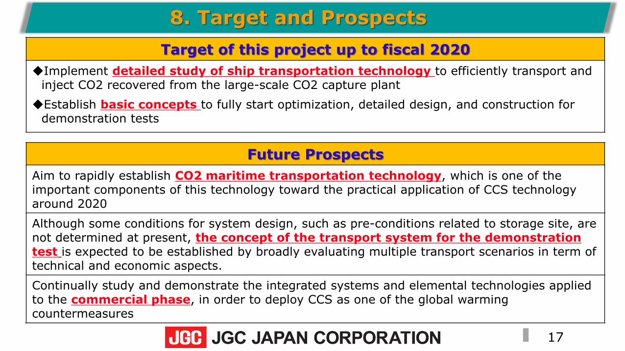
17Japan CCS Forum 2019
8. Target and ProspectsTarget of this project up to fiscal 2020
◆Implement detailed study of ship transportation technology to efficiently transport and inject CO2 recovered from the large-scale CO2 capture plant
◆Establish basic concepts to fully start optimization, detailed design, and construction for demonstration tests
Future ProspectsAim to rapidly establish CO2 maritime transportation technology, which is one of the important components of this technology toward the practical application of CCS technology around 2020 Although some conditions for system design, such as pre-conditions related to storage site, are not determined at present, the concept of the transport system for the demonstration test is expected to be established by broadly evaluating multiple transport scenarios in term of technical and economic aspects.Continually study and demonstrate the integrated systems and elemental technologies applied to the commercial phase, in order to deploy CCS as one of the global warming countermeasures