co2 transcritical systems training manual 042718€¦ · transcritical co 2 training manual i pg. 4...
TRANSCRIPT

CO2 Transcritical Systems Training ManualRevision 1, April 2018
www.hussmann.com

Table of Contents
Introduction................................................................................................................................................4
CO2asaRefrigerant....................................................................................................................................5
-GeneralCO2Information.......................................................................................................................8
-EnvironmentalBenefits.....................................................................................................................8
-SafetyConsiderations..........................................................................................................................10
-Asphyxiation....................................................................................................................................10
-Pressure...........................................................................................................................................11
-DryIce..............................................................................................................................................13
-Properties............................................................................................................................................15
-PHDiagram......................................................................................................................................15
-Pressure/Temperature....................................................................................................................16
-OtherProperties..............................................................................................................................16
SystemLayout...........................................................................................................................................18
-TranscriticalBoosterSystems..............................................................................................................18
-SystemSchematicCorrelationwithPHDiagram.................................................................................20
HussmannPuritySystem-PrimarySystemComponents........................................................................23
-FlashTank............................................................................................................................................24
-LowTemperatureLiquid/SuctionHeatExchanger(Optional).............................................................24
-Liquid/SuctionHeatExchangerBypassSystem(WhereApplicable)...................................................24
-ElectronicExpansionValves................................................................................................................24
-LowTemperatureCompressors..........................................................................................................25
-Evaporators.........................................................................................................................................25
-HotGasDefrostSystem.......................................................................................................................25
-FlashGasBypassValve........................................................................................................................25
-IntermediateHeatExchangers............................................................................................................25
-MediumTemperatureCompressors...................................................................................................26
-HeatReclaim........................................................................................................................................26
-HeatRejection.....................................................................................................................................26
-ThrottlingValve...................................................................................................................................26
-OilManagementSystems....................................................................................................................26

-Controls...............................................................................................................................................26
-EmergencyBack-UpSystems...............................................................................................................27
-ParallelCompression...........................................................................................................................27
InstallationGuidelines..............................................................................................................................28
-PressureRatings...................................................................................................................................28
-PipingMaterials....................................................................................................................................30
-Brazing..................................................................................................................................................31
-PipingPractices....................................................................................................................................31
-Supports...............................................................................................................................................32
-Insulation..............................................................................................................................................32
-ReliefValves.........................................................................................................................................33
EvacuationandCharging..........................................................................................................................34
-LeakTesting..........................................................................................................................................34
-PressureTesting...................................................................................................................................34
-Evacuation/Charging............................................................................................................................34
-OilCharging..........................................................................................................................................35
StartupandMaintenance.........................................................................................................................36
-StartupSequence................................................................................................................................36
-AfterStartup........................................................................................................................................37
-OilChanges..........................................................................................................................................37
AppendixA-HotGasDefrost...................................................................................................................39
-Introduction.........................................................................................................................................40
-Schematic............................................................................................................................................41
-HotGasDefrost-AdditionalConsiderations.......................................................................................41
Note:Thisdocumentispresentedfortrainingpurposesonlyandissubjecttochangewithoutnotice.Foradditionaltechnicalsupport,pleasecontacttheHussmannTechnicalSupportCenter:HussmannTechnicalSupportLine:1-800-592-2060.

TranscriticalCO2TrainingManualIPg.4
Introduction
TranscriticalCO2refrigerationsystemsaregainingacceptanceinthesupermarketrefrigerationindustry.NationalandinternationalpoliciesthatoriginallytargetedthereductionofCFCsarebeingexpandedtoincludeHCFCsandHFCs.TechnologyadvancementsinCO2systemsaremakingthesesystemsmoreeconomicallyviable,intermsofbothequipmentandinstallationcostbutalsoenergyandoperatingcosts.TheintentofthisdocumentistoserveasatrainingmanualtosupportHussmann’sCO2transcriticalboostersystemtraining.Thistrainingwilldescribeaspectsofthedesign,installation,andoperationofthesesystems.Thecurrentcontextforthistypeofsystemisprimarilysupermarketrefrigeration.
CO2asarefrigerantwillbecomparedtoHCFCssuchasR-22,andHFCssuchasR-404aandR407a,forthepurposesofthismanual.OtherHFOblendssuchasR448aandR449awillalsobecompared.Thecontenthereinispresentedwiththeassumptionthatusershaveknowledgeofhowtheserefrigerantsoperateindirectexpansionrefrigerationsystems.

TranscriticalCO2TrainingManualIPg.5
CO2 as a Refrigerant
CarbonDioxide,orCO2,isanaturallyoccurringcompoundinEarth’satmosphere.Itisthefourthmostcommonatmosphericcompound,behindnitrogen,oxygen,andargon.Carbondioxideisanintegralpartofthelifecycleofplantandanimals,astheprimaryproductofrespirationinanimalsandhumans,andtheprimarycarbonsourceforplantsviaphotosynthesis.
Inrecentdecades,carbondioxidehasbeenidentifiedasthemostsignificantgreenhousegasinEarth’satmosphere.Itiscurrentlyusedasthecomparativeunitofmeasurewhendiscussingtheglobalwarmingimpactsofvariousactivities,leadingtotheterm“carbonfootprint.”
CO2asarefrigeranthasemergedasoneofthefrontrunnerstobetherefrigerantofthefuture.Ithastheadvantagesofbeingenvironmentallyfriendly,hasgoodheattransferpropertieswithahighlatentheatofvaporization.CO2isalsonon-flammableandnon-toxic.TheprimarydisadvantageofCO2asarefrigerantisrelativelyhighoperatingpressures.Eachoftheseaspectswillbeexplainedaspartofthistraining.
Atranscriticalsystemisdefinedasasystemthatoperatesabovethecriticalpoint.ThefollowingchartshowsthePHdiagramofR-22,indicatingliquid,saturatedmixture,andgaseousstates.Thetopofthesaturated“dome”isthecriticalpoint.Abovethispoint,therefrigerantisnotconsideredliquidorgas,butanundefinedfluid.

TranscriticalCO2TrainingManualIPg.6
CO2 as a Refrigerant continued
R22 P/H Diagram
*DiagramcreatedusingREFPROP–NISTReferenceFluidProperties
Ascanbeseen,thecriticalpointofR-22ismorethan200°F,placingitwellabovetheoperatingconditionsoftypicalrefrigerationsystems.ThiscanbecontrastedwiththeCO2PHdiagram,withacriticalpointof88°F.Thistemperatureisoftenexceededwhenambientairisusedasthecondensingheatsink.

TranscriticalCO2TrainingManualIPg.7
CO2 as a Refrigerant continued
CO2 P/H Diagram
*DiagramcreatedusingREFPROP–NISTReferenceFluidProperties

TranscriticalCO2TrainingManualIPg.8
General CO2 Information
Environmental Benefits RegulationintheUnitedStatesregardingrefrigerantshasbeencenteredontwofactors,ozonedepletionpotential(ODP)andglobalwarmingpotential(GWP).ODP–OzoneDepletionPotentialODPisameasureofthepotentialofasubstancetoharmtheozonelayerifreleasedintotheatmosphere.ODPisaunitlessnumberrelativetoareferencevalue,usingR-11asthereferenceof1.0.SubstancesthathaveanODPofzeroareconsiderednottobeharmfultotheozonelayer.
GWP–GlobalWarmingPotentialGWPmeasuresthepotentialofasubstancetocontributetoglobalwarming.GWPquantifiesasubstanceinunitsofequivalentpoundsofCO2.Forinstance,R-404ahasaGWPof3940,meaningthatthereleaseofonepoundofR-404ahasthesameglobalwarmingeffectasthereleaseof3,940poundsofCO2.

TranscriticalCO2TrainingManualIPg.9
General CO2 Information continued
ThetablebelowshowstheODPandGWPofsomecommonrefrigerants.Alsoshownarethesafetyclassifications,perASHRAE34.
Refrigerant CommonName ODP GWPSafety
ClassificationR-11 1 4660 A1R-12 0.73 10800 A1R-22 0.034 1760 A1R-32 methylenefluoride 0 677 A2
R-134a 0 1300 A1R-290 propane 0 5 A3R-404A 0 3940 A1R-407A 0 1920 A1R-407C 0 1620 A1R-407F 0 1824* A1R-408A 0.02 3260 A1
R-410A 0 1920 A1R448a 0 1273* A1R449a 0 1397† A1R-507A 0 3990 A1R-717 ammonia 0 <1 B2
R-744 carbondioxide 0 1 A1Source:ASHRAEFundamentals2017,page29.5
*Source:HoneywellProductLiterature†Source:LindeProductLiterature
TheUnitedStatessignedtheMontrealProtocolin1987,committingtoeliminatetheuseofozonedepletingsubstances.AllmembersoftheUnitedNationseventuallysignedthetreaty.ThefirstphaseofthistreatytargetedCFCs,suchasR-12.In1992,thetreatyexpandedtophaseoutHCFCs,suchasR-22.Themostrecentamendment,knownastheKigaliAmendmentin2016,addedphasedownofHFCs.
Ironically,carbondioxideasarefrigeranthasanextremelylowcarbonfootprint,comparedtoallcommonsyntheticrefrigerants.TheabsenceofODPandextremelylowGWPmakeCO2attractiveasarefrigerantfromanenvironmentalandregulatoryperspective,becauseitisalreadysignificantlybelowcurrentlegallimits.

TranscriticalCO2TrainingManualIPg.10
Safety Considerations
ThephysicalpropertiesofCO2presentauniquesetofconsiderationstoensuresafety.CO2isclassifiedasanA1refrigerantbyASHRAEStandard34andtheInternationalMechanicalCode,meaningitisnon-toxicandnon-flammable.However,alargeenoughleakinaconfinedspacecandisplaceavailableoxygenforbreathing.Attypicalcommercialrefrigerationtemperatures,CO2operatesatahigherpressurethansyntheticrefrigerants.Whenreleasedatthesepressurestotheatmosphere,CO2canchangephasetosolidform,causingrestrictionsintheflowthatcanleadtoabuildupinpressure.
Asphyxiation AsanA1refrigerant,CO2isconsideredtohavelowtoxicityandlowflammability.TheconcernremainsthatalargeleakofCO2candisplaceexistingairinaspace,reducingtheoxygenlevels.Iftheoxygenlevelsarereducedconsiderably,thiscanleadtohealthhazardsuptoandincludingasphyxiation/death.Averageoutdoorairconsistsofaround400partspermillionofCO2,or0.04%.TheOccupationalSafetyandHealthAdministration(OSHA)hassetthepermissibleexposurelimitof5000PPM(0.5%)for8hoursperday(comparetomostHFCsat1000PPMallowable,CO2islesshazardous).Thetablebelowlistssomeadditionalconcentrationlevelsandtheeffectsonthehumanbody.
CO2Concentration Effects1%(1,000PPM) Breathingrateincreasesslightly.2%(2,000PPM) Breathingrateincreasesto50%abovenormallevel.Prolongedexposurecan
causeheadaches,tiredness.3%(3,000PPM) Breathingincreasestotwicethenormalrateandbecomeslabored.Weak
narcoticeffect.Impairedhearing,headache,increasedbloodpressureandpulserate.
4-5%(4,000-5,000PPM)
Breathingincreasestoapproximatelyfourtimesnormalrate,symptomsofintoxicationbecomeevident,andslightchokingmayoccur.
5-10%(5,000–10,000PPM)
Characteristicsharpodornoticeable.Verylaboredbreathing,visualimpairment,headache,andringingintheears.Judgmentmaybeimpaired,followedwithinminutesbylossofconsciousness.
10-100%(>10,000PPM)
Unconsciousnessoccursmorerapidlyabove10%level.Prolongedexposuretohighconcentrationsmayeventuallyresultindeathfromasphyxiation.
CO2atambientpressureisheavierthanair,soleakdetectionsystemsshouldbeplacedlow,typically18”abovethefloororasdictatedbylocalrequirements.

TranscriticalCO2TrainingManualIPg.11
Safety Considerations continued
Pressure CO2asarefrigerantoperatesathigherpressuresthantypicalHCFCsorHFCs,duetotheinherentthermodynamicpropertiesofthesubstance.Thetablebelowshowscomparablepressuresforsomecommonrefrigerantsatthreedifferentsaturatedoperatingconditions.
SystemOperatingPoint R-22 R-404a R-407a R-744(CO2)LowTemperatureEvaporation(-25°F) 7.4 12.9 -2.7 181MediumTemperatureEvaporation(+20°F) 43.1 55.8 34 407.2CondensingPressure(86°F) 158.2 191.4 165.6 1031.5*Allpressureslistedinpsig
HFCdirectexpansion(DX)refrigerationsystemsareoutfittedwithasinglepressurereliefdevicelocatedatthereceiver.Thispressurereliefdeviceisratedforpressuresaround400psig,dependingontherefrigerantused.Additionalmechanicalsafetiesandcontrolsetpointsshutthesystemdownaround350psigdischargepressuretopreventanyrefrigerantfromdischargingthroughthepressurereliefsafetyvalve.Theentirepipingsystemisratedforworkingconditionsabovethesafetyreliefpressure,sonosecondaryreliefdevicesarenecessary.Iftherefrigerationsystemshutsdownduetopoweroutageorservicing,theinternalpressuresdonotexceedtheratedpressure.
ThehighsaturatedpressureofCO2atsummertimeambientconditionsexceedsthepressureratingoftypeKcopperpiping,alongwithmoststandardDXrefrigerationvalves.Thisrequiresthe“highside”oftheCO2systemtobeconstructedusinghigherpressureratedmaterialsandinstallationpractices,atahighercost.Toreduceoverallsysteminstalledcost,the“lowside”portionsofaCO2systemaredesignedfortheloweroperatingpressures,allowingcoppertobeusedforthelowsidepiping.Whenthesystemisoperatingnormally,pressuresaremaintainedbelowtheratedpressureofthesystem.
TranscriticalCO2TrainingManualIPg.12
Safety Considerations continued
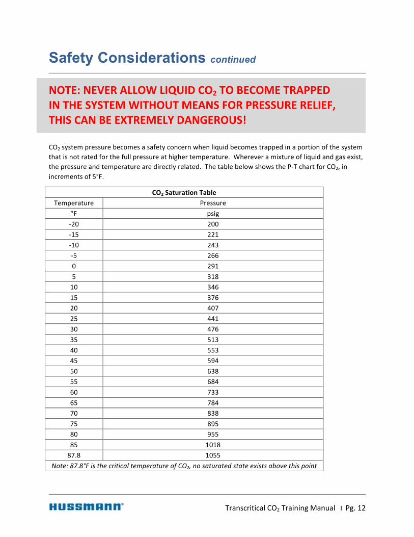
NOTE:NEVERALLOWLIQUIDCO2TOBECOMETRAPPEDINTHESYSTEMWITHOUTMEANSFORPRESSURERELIEF,THISCANBEEXTREMELYDANGEROUS!CO2systempressurebecomesasafetyconcernwhenliquidbecomestrappedinaportionofthesystemthatisnotratedforthefullpressureathighertemperature.Whereveramixtureofliquidandgasexist,thepressureandtemperaturearedirectlyrelated.ThetablebelowshowstheP-TchartforCO2,inincrementsof5°F.
CO2SaturationTableTemperature Pressure
°F psig-20 200-15 221-10 243-5 2660 2915 31810 34615 37620 40725 44130 47635 51340 55345 59450 63855 68460 73365 78470 83875 89580 95585 101887.8 1055
Note:87.8°FisthecriticaltemperatureofCO2,nosaturatedstateexistsabovethispoint

TranscriticalCO2TrainingManualIPg.13
Safety Considerations continued
Asthetemperatureofasaturatedmixturerises,pressurewillriseuntilitreachesthesaturationpressureinthetableabove.Iftherefrigerantpressureexceedstheratingofthepiping,valves,orothercomponentsofthesystem,thiscanleadtoleaksandpossiblyburstingofsystemcomponents.
Tominimizetheriskofpressurebuildupinthesystem,measuresmustbetakeninsystemdesigntoensurethatpressurecannotbuildupinanyportionofthesystem.Allcomponents,valves,piping,fittings,andjoiningmethodsmustbeverifiedtoensurepressureratingsabovethemaximumanticipatedsystempressures.Pressurereliefdevicesmustbelocatedappropriatelytoallowthesystemtoventsafelyintheeventofasystemshutdownorothereventthatcausespressuresabovesystemratings.Allpointswithinthesystemmustbeallowedtoventbacktothepressurereliefvalveswithoutrestriction.Checkvalvesaretypicallyutilizedtoallowportionsofthesystemtoventbacktoreceivers,wherepressurereliefvalvesarelocated.Anyportionofthesystemthatcannotventbacktothereceivermusthaveitsownpressurereliefvalve.
Dry Ice PressurereliefdevicesontraditionalDXrefrigerationsystemsarelocateddirectlyontheoutletofthereceiver,andthenpipedoutdoorsforsafedischarge.ThispracticewouldbehazardousifappliedtoaCO2system,duetotheformationofdryice.
DryiceissimplyCO2insolidform.ThePHdiagramofCO2isshownbelow,includingtheregionwherethesolidstatecanexist.

TranscriticalCO2TrainingManualIPg.14
Safety Considerations continued
*DiagramcreatedusingREFPROP–NISTReferenceFluidProperties
Inarefrigerationsystem,therearetwocommonconditionswherethismayoccur.Thefirstandpotentiallydangerouslocationisatapressurereliefvalve.Whenapressurereliefvalveisopen,therefrigerantisundergoingarapiddropinpressurefromsystempressuretoatmosphericpressure.IfliquidCO2isbeingreleased,thePHdiagramshowsthatadropbelowthetriplepointpressureof75.1psia(60.4psig)willresultinasolidandvapormixture.Forthisreason,pressurereliefvalvesshouldnothaveanypipinginstalleddownstreamofthevalve.Ifthepressuredrophappensinsidethepipe,dryicewillform,blockingflowandpreventingpressurefrombeingreleased.
Thesecondconditionwheredryicemayformiswhenchargingthesystem.Ifsystemvacuumisbrokenwithliquid,dryicecanforminsidethesystem,againrestrictingflow.Thisconditionislessdangerousbecauseitdoesnotcausepressurebuildupbeyondsystemratings,butshouldstillbeavoided.

TranscriticalCO2TrainingManualIPg.15
Properties
ThepropertiesofCO2havebenefitsaswellaschallengeswhencomparedtocommonsyntheticrefrigerants.Someofthesepropertieshavebeendescribedinprevioussectionsastheypertaintosafetyandenvironmentalconsiderations.ThefollowingsectionswilldescribekeypropertiesofCO2astheypertaintotheoperationofarefrigerationsystem.
PH Diagram ThepressureenthalpydiagramforCO2isshownbelow.
*DiagramcreatedusingREFPROP–NISTReferenceFluidProperties
SeveralcharacteristicscanbereadilyseenonthePHdiagram.
1. Saturatedregion–ThegeneralshapeoftheCO2PHdiagramissimilartootherrefrigerants;onlythespecificvaluesaredifferent.
2. Criticalpoint–thecriticalpointofCO2is1070psia(1055.3psig)and87.8°F.Thisishighestpressureandtemperaturewhereliquidandgascanexistsimultaneously.Theregionabovethispointisconsideredsupercritical,belowthispointissubcritical.
TranscriticalCO2TrainingManualIPg.16
Properties continued
3. Flatconstanttemperaturelinesinthesaturatedregion–CO2isapuresubstance,soitdoesnothaveatemperatureglidebetweenthesaturatedliquidandsaturatedvaporlines.Thismeansevaporatortemperatureswillremainconstantthroughouttheevaporatorcoil,allowingeasymeasurementofsuperheat.
4. Solid/Vaporregion–belowthetriplepointtemperatureof-69.8°F,CO2existsasamixtureofsolidandgas.Notethatthetriplepointpressureis75psi,meaningthatifaliquidorsaturatedmixtureisreducedtothispressure,itwillchangephasetoasolid/vapormixture.Thetriplepointofcommonsyntheticrefrigerantsisoutsideofthefeasiblerangefortemperatureandpressure,andisnotshownonmostP/Hdiagrams.
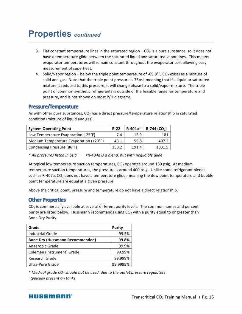
Pressure/Temperature Aswithotherpuresubstances,CO2hasadirectpressure/temperaturerelationshipinsaturatedcondition(mixtureofliquidandgas).
SystemOperatingPoint R-22 R-404a† R-744(CO2)LowTemperatureEvaporation(-25°F) 7.4 12.9 181MediumTemperatureEvaporation(+20°F) 43.1 55.8 407.2CondensingPressure(86°F) 158.2 191.4 1031.5
*Allpressureslistedinpsig †R-404aisablend,butwithnegligibleglide
Attypicallowtemperaturesuctiontemperatures,CO2operatesaround180psig.Atmediumtemperaturesuctiontemperatures,thepressureisaround400psig.UnlikesomerefrigerantblendssuchasR-407a,CO2doesnothaveatemperatureglide,meaningthedewpointtemperatureandbubblepointtemperatureareequalatagivenpressure.
Abovethecriticalpoint,pressureandtemperaturedonothaveadirectrelationship.
Other Properties CO2iscommerciallyavailableatseveraldifferentpuritylevels.Thecommonnamesandpercentpurityarelistedbelow.HussmannrecommendsusingCO2withapurityequaltoorgreaterthanBoneDryPurity.
Grade PurityIndustrialGrade 99.5%BoneDry(HussmannRecommended) 99.8%AnaerobicGrade 99.9%Coleman(Instrument)Grade 99.99%ResearchGrade 99.999%Ultra-PureGrade 99.9999%
*MedicalgradeCO2shouldnotbeused,duetotheoutletpressureregulatorstypicallypresentontanks

TranscriticalCO2TrainingManualIPg.17
Properties continued
TheuseofBone-Drygradeensuresproperoperationoftheequipmentandispureenoughtopreventaccumulationofnon-condensablegasesinthesystem.MixingofhigherpuritygradesofCO2isacceptable.LowergradesofCO2willbelessexpensive,butarenotrecommendedforuseinHussmannPuritysystems.Thesecontainhigherlevelsofcontaminantsandwater,andmaydecreasesystemperformance.HigherlevelsofmoisturemayreactwiththeCO2andformcarboxylicacidthatcandegradecomponentintegrity.Hussmannrecommends,dependingonlocationandavailabilityofCO2,thatenoughrefrigerantchargebekeptonsitetofilltheentiresystem.
OneofthebenefitsofCO2comparedtosyntheticsisahighvapordensity.R-22hasadensity0.43lb/ft3leavinga-25°Fevaporator.CO2inthissameconditionhasadensityof2.2lb/ft3,roughly5timesmoredense.Inpractice,thistranslatestosmallerpipesizes,becausethesamemassflowcanoccuratamuchlowervolumetricflowrateandassociatedvelocitythanmostsyntheticrefrigerants.
15MBH@-20°F R-404a CO2
1-1/8”Suction ½”Liquid 5/8”Suction 3/8”Liquid
15MBH@+20°F R-404a CO2
7/8”Suction ½”Liquid 1/2”Suction 3/8”Liquid

TranscriticalCO2TrainingManualIPg.18
System Layout
Transcritical Booster Systems CO2hasfounduseinthesupermarketindustryinawidevarietyofsystemlayouts.EarlyadoptionintheUnitedStateswasprimarilyasalowstagefluid,withaprimaryrefrigerantprovidinghighsidecooling.Thisallowedoperatingpressurestoremainlowwithgoodefficiency.Thiswasappliedbothasapumpedsystemandasacascadedirectexpansionsystem.Bothsystemtypeshaveprosandcons,andcanbereferencedinmoredetailinotherdocumentation.
TranscriticalCO2systemoperatewithoutanyotherrefrigerant,rejectingheatremovedfromrefrigeratedcasesandwalk-inboxesdirectlytowaterorambientair.AbasicschematicofaCO2transcriticalsystemwithflashgasbypassisshownbelow.

TranscriticalCO2TrainingManualIPg.19
System Layout continued
Thesystemisdividedintotwostages,lowandhigh.Thelowstagebeginsattheoutletofthehighpressureexpansion(throttling)valve.Here,amixtureofliquidandgasispipedintotheliquid/vaporseparator.Fromthebottomoftheseparator,liquidCO2at20-30°Fisfedtothelowtemperatureevaporatorsthroughanexpansionvalve.TheCO2isfullyevaporatedandreturnedtothelowstagecompressorsasavapor.Lowstagecompressorsdischargeintotheinletofthehighstagecompressors.Mediumtemperatureevaporatorsarefedwiththesameliquidasthelowtemperatureevaporators.Vaporfrommediumtemperatureevaporatorsispipeddirectlytothesuctioninletofthehighstageevaporators.Athirdrefrigerantstreamknownasflashgasisalsopipeddirectlyfromthetopoftheliquid/vaporseparatorthroughaflashgasbypassvalvetothesuctionsideofthehighstagecompressors.
Highstagecompressorstakelowstagedischarge,mediumtemperaturevapor,andflashgasandcompressthemuptoapressuresufficienttorejecttheheatfromthesysteminthegascooler/condenser.Thegascoolerisnamedassuchbecausetherefrigerantisnottechnicallycondensingifitisoperatingintranscriticalmode.Atpressuresabovethecriticalpointknownasthesupercriticalregion,therefrigerantisconsideredanundefinedfluid,andcannotbecalledliquidorvapor.Dependingonambientconditionsorthetemperatureoftheheatsink,transcriticalsystemscanoperateeithertranscriticallyorsubcritically.Thisoperationiscontrolledprimarilybythethrottlingvalve.Theseoperatingmodeswillbedescribedinmoredetailinthehighstagesectionbelow.

TranscriticalCO2TrainingManualIPg.20
System Layout continued
System Schematic Correlation with PH Diagram Thediagrambelowshowsthesamegenericsystemschematic,withstatepointsidentifiedwithnumbers.

TranscriticalCO2TrainingManualIPg.21
System Layout continued
ThisschematiccanbecorrelatedwiththePHdiagramasshownbelow.
*DiagramcreatedusingREFPROP–NISTReferenceFluidProperties
1. Enteringtheliquid/vaporseparatora. Therefrigeranthasleftthethrottlingvalveandisnowaliquid/vapormixtureatan
intermediatepressure,normallyaround480psi.Dependingonthegascoolerpressureandtemperature,thismixturewillhaveaqualityaround0.3,meaningitis70%liquid,30%vapor(bymass).Themixtureseparatesintoliquidandvaporintheseparatorduetothedifferenceindensityofthetwostates.
2. Leavingtheliquid/vaporseparatorfromthebottoma. Locatedatthebottomofthevessel,therefrigerantleavesthevesselasasaturated
liquid,typicallyaround30°Fand480psig.3. Enteringmediumtemperatureevaporators
a. Liquidrefrigeranttravelsthroughanexpansionvalveandleavesatevaporatorpressure.Asmallamountofexpansionhappensinthevalveandtherefrigerantentersasanearlysaturatedliquid,at20°Fand410psig.

TranscriticalCO2TrainingManualIPg.22
System Layout continued
4. Leavingmediumtemperatureevaporatorsa. Refrigeranthasboiledcompletelyandhasasmallamountofsuperheatat410psig.
5. Enteringlowtemperatureevaporatorsa. Saturatedliquidfromtheseparatorhaspassedthroughthelowtemperatureexpansion
valveandisnowatlowtemperatureevaporatorpressure,typicallyaround-20°Fand200psig.
6. Leavinglowtemperatureevaporatorsa. Therefrigeranthasboiledcompletelyandhasasmallamountofsuperheatat200psig.
Thisisalsothelowtemperaturecompressorsuction.7. Flashgasbypassvalve
a. Flashgashaspassedthroughtheliquid/vaporseparatorasasaturatedvapor,ataround480psia.Theflashgasbypassvalvemetersthisflowtocontrolliquid/vaporseparatorpressureandhighstagesuctionsuperheat.
8. Lowtemperaturecompressordischargea. Lowtemperaturecompressordischarge-Refrigeranthasbeencompressedtoslightly
abovethehighstagesuctionpressure,around410psi.Italsohassignificantsuperheat,leavingataround200°F.
b. Lowtemperature9. Highstagecompressorsuction
a. Thehighstagecompressorsuctionheaderistheconvergencepointofthreeflows.i. Lowtemperaturecompressoroutletii. Mediumtemperatureevaporatoroutletiii. Flashgasbypassvalveoutlet
10. Highstagecompressordischargea. Therefrigeranthasbeencompressedandisnowatthehighesttemperatureand
pressureinthesystem.Dependingonambientconditions,thistemperaturemayreach250–300degreesFand1350-1500psi.Inthisexample,thisisalsotheinletconditionofthegascooler.Theconditionatthisstatepointcanvarywithfluctuationsinloadortemperatureoftheheatsink.Forair-cooledsystems,lowambientconditionsoftenallowthesystemtooperatesubcritically,minimizingthepressurerequiredandassociatedenergyconsumption.Primarilythethrottlingvalve,alongwithgascoolercapacitymodulation,controlsthepressureatthispoint.
11. Gascooler/condenseroutleta. Heathasbeenremovedfromtherefrigerantinthegascooler.Intranscriticalmode,the
refrigerantatthispointisanundefinedfluid,notliquidorgas.Insubcriticalmode,therefrigerantatthispointisaliquid.
12. Throttlingvalveoutleta. Refrigerantfromthegascoolerhasbeenreducedinpressuretotheliquid/vapor
separatorpressure.Intranscriticalmode,therefrigeranthereisamixtureofliquidandgas.Insubcriticalmode,therefrigerantis100%liquid.

TranscriticalCO2TrainingManualIPg.23
Hussmann Purity System - Primary System Components
ThefollowingsectionswilldescribeoperationalanddesignaspectsofthekeycomponentsoftheHussmannPuritySystem.Theschematicofthissystemisshownbelow.

TranscriticalCO2TrainingManualIPg.24
Hussmann Purity System continued
Ascanbeseen,therearesomevariationsfromtheexampleschematicshownintheprevioussection.First,thereisaliquid/suctionheatexchangerbetweentheliquidfeedtothelowandmediumtemperatureevaporatorcoilsandthelowtemperaturesuctiongas.Thepurposeofthiscomponentistoensurecompletelysaturatedandpossiblysubcooledliquidisfedtotheelectronicexpansionvalves.Italsoservedtoensureadequatesuperheatbacktothelowtemperaturecompressors,preventingliquidfloodback.Thisheatexchangerisequippedwithseriesofvalvestoallowvaporflowtobypasstheheatexchangerforsuperheatcontrol.Second,aheatexchangersisusedtowarmthevaporenteringthehighstagecompressors,ensuringadequatesuperheat.Thisheatexchangerhasabypassvalvetocontrolthissuperheat.Finally,nodesuperheaterisusedonthelowtemperaturecompressors.Notshownontheschematicistheliquidinjectionsystem,whichallowsomissionofthisdesuperheater.
Flash Tank Theflashtankisalsoknownastheliquid/vaporseparator.Thisvesselservesseveralpurposes.Itprovidesalocationwithlowvelocitytoallowtimeforthefluidleavingthehighpressureexpansionvalvetoseparateintoconstituentliquidandvapor.Itallowsthevaportobypassthemajorityofthelowsideofthesystemandreenterthehighstagecompressors.
Thepressureoftheflashtankiscontrolledbytheflashgasbypassvalve.Thisvalveensuresproperflowthroughthemediumtemperatureevaporators.
Flashtanksaresizedtoallowanappropriateinterfaceareaforproperseparationofliquidandvapor,aswellasvolumetoallowformassfluctuationsintheremainderofthesystem.
Low Temperature Liquid/Suction Heat Exchanger (Optional) Thelowtemperatureliquid/suctionheatexchangertransfersheatfromtheliquidtothevapor.Thisservestwofunctions.Theprimaryfunctionistoprovideadditionalsuperheattothevaporleavingthelowtemperatureevaporators,ensuringnoliquidfloodbackoccurstothecompressors.Italsocoolstheliquidbelowthesaturatedcondition,ensuring100%liquidisprovidedtotheexpansionvalves.Thisalsoaidsinoilflowtothecompressors.Thisunitissizedtoprovideadequateheatexchangewithminimalpressuredropespeciallyonthevaporside.
Liquid/Suction Heat Exchanger Bypass System (Where Applicable) HussmannPurityracksutilizeaseriesofmodulatingvalvestoallowsuctiongastobypassthelowtemperatureliquid/suctionheatexchanger.Thesevalvescontrolbasedonreturngastemperature,ensuringtheappropriateamountofsuperheatenteringthelowtemperaturecompressors.Thissystemtargetsaminimumof36°Fcompressorsuperheat.Thisalsoaidsinoilflowtothecompressors.
Electronic Expansion Valves CO2systemsutilizeelectronicexpansionvalves(EEVs)insteadoftraditionalthermostaticexpansionvalves(TXVs).Individualcasecontrollersprovidecontrolofthesevalves.EEVsarenecessarywithCO2duetoimprovedresponsetimesandabilitytobeadjustedbythecontroller.Thesevalvesaretypicallysuppliedfactorypipedinrefrigeratedcases.Walk-inevaporatorsmaybefactoryorfieldpiped.
TranscriticalCO2TrainingManualIPg.25
Hussmann Purity System continued
Low Temperature Compressors LowtemperaturecompressorsoperateverysimilarlytotraditionalDXHFCcompressors.Suctiongasiscompressedfromlowtemperatureevaporatorpressure,typicallyaround200psi,uptotheinletpressureofthemediumtemperaturecompressors,typicallyaround400psi.Aswithtraditionalsystems,compressorsarecycledtomaintainsuctionpressure.Thesecompressorshaveliquidinjection,tomitigatehighdischargetemperatures.
Evaporators EvaporatorsforCO2systemsmustbedesignedspecificallyforCO2,duetothehigheroperatingpressuresthantypicalHFCsystems.Inadditiontopressureratings,theseevaporatorsaredesignedtominimizeinternalvolume,topreventrapidpressurebuildupintheeventofasystemshutdown.NormaloperatingpressuresforlowtemperatureCO2evaporatorsrunat200psi,whilemediumtemperatureevaporatorsrunat400psiorhigher.Regardlessofoperatingpressure,theevaporatorsmustbedesignedtoresistpressuresabovethepressurereliefsettings.
Hot Gas Defrost System HussmannPuritysystemsareavailablewithoptionalhotgasdefrostsystemsforlowtemperatureandmediumtemperatureevaporators.Thissystemisdescribedinmoredetailinaccompanyingdocuments.
Flash Gas Bypass Valve Theroleoftheflashgasbypassvalveistoregulatethepressureintheflashtank.The“flashgas”isthevaporportionoftherefrigerantfluidmixturecomingfromthegascooler.Thisportionwillvarybasedonloads,ambientconditions,andpressuresettingsinthegascooler,normallybetween25%and50%bymass.Thepressureinthetankismonitoredbythecontrollerandtheflashgasbypassvalveisopenedwiderifpressureneedstobereduced.Conversely,thevalvemodulatesclosediftankpressureneedstobeincreased.
Intermediate Heat Exchangers Themediumtemperaturesystememploysasimilarliquid/suctionheatexchangerstrategyasthelowtemperatureportionofthesystem.Fluidleavingthegascoolerisusedtoprovideheattosuctiongas.Aswiththelowtemperaturesystem,bypassvalvesaremodulatedtomaintainappropriatesuperheattothemediumtemperaturecompressors.Thisalsoprovidescoolingtothegascooleroutletfluid,ultimatelyreducingtheamountofflashgas.Thisheatexchangermustberatedtofullgascoolerpressure,typically1600psi.
TranscriticalCO2TrainingManualIPg.26
Hussmann Purity System continued
Medium Temperature Compressors MediumtemperaturecompressorsalsooperateverysimilarlytotraditionalDXHFCcompressors.Suctiongas(comprisedofflashgas,lowtemperaturecompressordischarge,andmediumtemperatureevaporatorsuction)iscompressedfrommediumtemperatureevaporatorpressure,typicallyaround400psi,uptothepressurerequiredforheatrejection,upto1350psi.Compressorscycletomaintainsuctionpressure.Theoutletofthesecompressorsisthepointofhighestpressureandhighesttemperaturewithintheentiresystem.
Heat Reclaim HussmannoffersanoptionalheatreclaimsystemwithPuritysystems.Thisheatreclaimisavailableinseveralconfigurations.ThefirstconfigurationplacesaCO2coilinanairhandlerfordirectrefrigeranttoairheatreclaim.Thesecondconfigurationutilizesasinglewallheatexchangetoheatanintermediateglycolfluid,whichispipedtoanairhandlerorothersystemtoutilizetheheat.Thethirdconfigurationutilizesadoublewallheatexchangerfordomesticwaterheating.
Thestandardconfigurationofthissystemistopipetheheatreclaimheatexchangerinparallelwithamotorizedballvalveandamodulatingvalve.Thesevalvesmodulatetobypassaportionofthecompressordischargearoundtheheatreclaimsystem.Valvesshouldbedesignedandsetsuchthatifthemotorfails,thevalvemovestoapartiallyopenpositiontopreventheadpressurebuildup.
Heat Rejection Gascoolersaretypicallyaircooleroradiabatic(hybrid).Forair-cooledgascoolers,fansaremodulatedbasedonsetpointsdefinedbythecontroller.Adiabaticgascoolersutilizewetprecoolingpadstocoolincomingairpriortoenteringthegascoolingportionoftheunit.
Throttling Valve Thethrottlingvalveistheprimarycontrolforgascoolerpressure.Becausetemperatureandpressureareindependentfromoneanotherinthesuper-criticalregion,gascoolerpressureisnotascloselycorrelatedtoambientconditionsastypicalair-cooledcondensers.Optimumgascoolerpressureforsystemefficiencyandcapacityiscalculatedusingcomplexalgorithms.
Oil Management Systems Hussmannappliesapatentedmethodforstablelubricationofthecompressors.Thislowpressure(60-80psiaboveMTsuction)systemusesstandardoilcontrolsonallcompressors.
Controls HussmannPuritysystemsarecompatiblewithproductsavailablefromseveralcontrolsystemsmanufacturers,dependingonownerpreference.TheseincludeDanfoss,CPC,andMicroThermo,amongothers.Hussmannsystemscomestandardwithfactoryinstalledbatterybackupsystemsforcontrollersandcriticalvalves,toensuresystemsafetyandpreventliquidfloodbackduringpoweroutages.

TranscriticalCO2TrainingManualIPg.27
Hussmann Purity System continued
Emergency Back-Up Systems Emergencyback-upsystemsareanoptionalcomponentofaCO2system.Thesesystemsconsistofasmallcondensingunit,fedwithemergencypower.Thiscondensingunitprovidescoolingtoanevaporatorintendedtomaintainflashtanktemperatureandassociatedpressurewhentheremainingportionofthesystemisoff,suchasduringapoweroutage.Thispreventspressureintheflashtankfromrisingabovethepressureratingofthesystem,thuspreventingdischargeofCO2throughthepressurereliefsystem.
Parallel Compression Hussmannoffersparallelcompressionasanoption.Themodificationtotheschematicisshownfollowing:
Withthissystem,theflashgasiscompressedinaseparatesuctiongroupfromthemediumtemperatureloadsandlowtemperaturedischarge.Thisimprovesenergyefficiencyofthesystembyallowingthehigherpressure“load”tobecompressedatanimprovedCOP(coefficientofperformance).(Parallelcompressionstrategiesareunderdevelopment,futurecontenttobeadded)

TranscriticalCO2TrainingManualIPg.28
Installation Guidelines
HussmannPuritysystemsareinstalledmuchlikeatraditionalDXsystem,withafewimportantdifferences.ThesedifferencesareprimarilyduetothehigheroperatingorpotentialpressuresfoundinCO2systems.
Pressure Ratings PipingmaterialsforCO2systemsmusttakeintoaccountthepressureratingneededforthespecificapplication.Whilevariouspointsinthesystemexperiencearangeofpressures,Hussmannrecommendsonlytworatinglevels.Thishelpsensuresystemsafetyandavoidconfusioninpiping.Thesetwopointsarebestdescribedaslow-pressureandhigh-pressure.Thedividingpointsoftheseregionsisshownintheschematicbelowwithorangeindicatinghighpressureandblueindicatinglowpressure.

TranscriticalCO2TrainingManualIPg.29
Installation Guidelines continued
Thehigh-pressureportionofthesystembeginsattheoutletofthemediumtemperaturecompressors,continuesthroughtheheatreclaimsystemandgascooler,andendsatthehigh-pressureexpansionvalve.Pressurereliefdevicessetat1600psiprotectthisportionofthesystem.Allcomponentsandpipinginthisportionofthesystemmustbecapableofwithstandinginternalpressuresofmorethan1600psi.

TranscriticalCO2TrainingManualIPg.30
Installation Guidelines continued
Thelow-pressureportionofthesystembeginsattheoutletofthehighpressureexpansionvalve,andincludestheremainderofthesystem.Thisincludestheentirelowtemperatureportionofthesystem,theflashtank,andthesuctionsideofthemediumtemperaturecompressors.Pressurereliefdevicessetat650psiprotectthisportionofthesystem.Nocomponentinthesystemshouldberatedatlessthan650psi.
Tomaintainsafetyofthesystemwithminimalpressurerelieflocationsandcost,bypasscheckvalvesareplacedaroundpotentialrestrictionsinthesystem.Thesecheckvalvesallowflowbacktotherackifthesystemisshutdown,butremainclosedundernormalsystemoperation.Anexampleofthisisshownbelow.
Piping Materials Toachieveapressureratingabove650psiforthelowsidepiping,severalpipingmaterialsareavailable.Theseincludecertaincopperproducts,copper-ironalloyproducts,andstainlesssteel.
TypeKCopper–TypeKcoppermaybeusedforpipinginthelowsideofthesystem,upto1-1/8”pipesize(only7/8”forhotgassystems).Asthepipesizesgetlarger,thepressureratingsgodown.Pipesizesof1-3/8”andabovearenotadequatelypressureratedforCO2intypeK.AtableofratedworkingpressuresforTypeKcopperisprovidedbelow.
TypeKCopperRatedWorkingPressures MuellerXHPPipe-Nominal
ODS-6000psi,
100°FS-5100psi,
150°F90Bar/1300PSI,
250°F130Bar/1885PSI,
250°F3/8" 1074 913 1093 1093
1/2" 1130 960 809 10935/8" 891 758 809 10787/8" 852 724 799 109311/8" 655 557 824 112513/8" 532 452 834 111215/8" 494 420 824 110921/8" 435 370 846 1127
25/8" 398 338 842 1141

TranscriticalCO2TrainingManualIPg.31
Installation Guidelines continued
K-65–K-65isacopperalloythatcontainsiron,producedbyWieland.K-65isavailableatapressureratingof120bar(1740psi),makingitviablefortranscriticalCO2systems.Thispipingmaybeusedinthehighorlowsidepipingofthesystem,usingthecorrectfittingsandinstallationpractices.Note:K-65isnotapprovedforuseinsomejurisdictions,verifylocalcodedbeforeproceeding.
XHP–XHPisacompetitortoK-65,availablefromMueller.Thisproductisavailableinseveralpressureratings,socaremustbetakentousetheappropriatepipingfortheapplication.AswithK-65,joiningmethodsaresimilartotraditionalcopperrefrigerantpiping.Note:XHPisnotapprovedforuseinsomejurisdictions,verifylocalcodedbeforeproceeding.
Stainlesssteel–priortotheintroductionofK-65andXHPtothemarket,stainlesssteelwasrequiredforuseonallhighsidepiping.Thisisstillaviableoption.ForCO2pressurerating,buttweldsarenotallowedforjoints;appropriatefittingsmustbeused.
AswithtraditionalDXsystems,shortradiusfittingsarenotrecommended.Longradiusellsareavailablefromseveralmanufacturers.Alwaysbesuretouseappropriatepressureratedfittings.
Brazing Allweldedjointsshouldbemadeupusing15%silver"Silphos."Use45%to56%silver"EasyFlo"onsweatvalvesandothercontroldevices.Buttweldsshouldnotbeused;alwaysuseappropriatefittings.Extremecareshouldbetakentokeeptheentiresystemcleananddryduringinstallation.Nitrogengasshouldflowthroughthepipingbeingweldedtopreventoxidation(scaling)duringtheweldingoperation.Aflowmetershouldbeinstalledtoensureappropriateflowrates.Jointsshouldbeallowedtoaircool;therapidcoolingfromawetragwillcausestrengthissuesinthejointleadingtoleaks.
Piping Practices ManyofthebestpracticesusedfortraditionalrefrigerationpipingareapplicabletoCO2systempiping.Undernoconditionsshouldcopperpipestoucheachother,solidstructure,sharpedges,othermetals,foreignobjects,etc.,duetotheriskofabrasionandresultingleaks.Whennecessarytocrosspipes,theyshouldbeoffsetorinsulated(andproperlysupported)toensurethereisnocoppertocoppercontact,orcontactwithothermetals.Nylonorplasticspacers(asmanufacturedbyHydra-Zorb)shouldbeusedbetweenun-insulatedtubingandclampstopreventlinechafinginthecases.Besuretousehightemperatureinsertswhensupportingdischargeanddrainlines.Allunderslabsuctionlinesandothersuctionlineswithverticalriserslongerthan6ft.shouldhavea"P"typeoiltrapinstalledatthebottom.Risersgreaterthan16feettallshouldhaveaninvertedtrapatthetopoftheriser.Suctionlinesshouldbeslopeddownwardinthedirectionofflow.

TranscriticalCO2TrainingManualIPg.32
Installation Guidelines continued
Individualcircuitpipingshouldberoutedwithagoalofequalpressuredroptoallevaporators,especiallyforhotgassystems.Thefigureontheleftbelowlooksgoodonaschematic,butisnotgoodpipingpracticemultipleevaporatorswithinonehotgascircuit.SeeappendixAformoreinformationonhotgassystems.
Acceptableforelectric Requiredforhotgasdefrostorofftimedefrostonly
Supports Commercialgradenylonstopnutsshouldbeusedonallclamps.Supportchannelsshouldbe"Unistrut"P-4000orheavier.Clampsshouldbeinthe"Unistrut"seriesP-2024to2043.Alternatechannel"SuperStrut"A-1200,B-1200,A-1202,B-1202withseriesA-716O.D.clamps,"WesancoInc."W-200,W-500ChannelwithseriesW-6229toW-6243O.D.clamps,or5-1/2”x1-5/8”16gaugegalvanizedsteel“C”stud.
AlloverheadsuctionandliquidlinesshouldbesecuredwithHydra-ZorbtypeclampsunlessonoverheadhorizontalrunsusingtrapezehangerswithInsulguardsaddles,whichshouldbesecuredtotheunistrutwithzipscrews.Iftheprojectisinseismiczone,pipingandequipmentshouldbebraced,supportedandinstalledtocomplywithlocationrequirements.Clampallverticallinesandlinesfromandtothegascoolerwithunistrutatleastevery6'.Allhorizontallinesneedtobesupportedwithunistrutatleastevery8'.
Insulation PipinginsulationshouldbeArmacell"Armaflex"orRubatex"Insul-Tube180".AlljointsshouldbesealedwithArmacell#520,RubatexR-374whitelatexpaintorRubatex"R-320"adhesive.HeatReclaimlinesshouldbeinsulatedwithArmacell“HT/Armaflex”orequivalentRubatexinsulation.Suctionlinesformediumtemperaturesystemsshouldhave3/4"wallthicknessinsulationfromfixtureorcoiloutlettothecompressorunlessotherwisenotedonplans.Suctionlinesforlowtemperaturesystemsshouldhave1"wallthicknessinsulationfromfixtureorcoiloutlettothecompressor.Alldischargelinestoheatreclaimcoilandwaterheatershouldbeinsulatedwith1/2"wallthicknessinsulation.Liquidlinesshouldbeinsulatedwith1/2"wallthicknessinsulation.Insulationmaybeslippedoverpiping,onlysplitwheninsulationcannotbeslippedon.

TranscriticalCO2TrainingManualIPg.33
Installation Guidelines continued
Relief Valves Itisveryimportantthattheproperpipingbeinstalledforthereliefvalves.Hussmannwillsupplythe4reliefvalvesandthechange-overforthelowside.Thesevalveswillautomaticallyopenat650psi.Forthehighside2reliefvalvesandachange-overwillbesuppliedinwhichthevalvesareregulatedfor1600psi.Twocopperlinesandonestainlesssteellinemustbepipedoutside.Itisveryimportantthatlocalcoderequirementsbefollowed.
1. Highpressurereliefline1600psimustbein“Stainlesspipeschedule40withadiameterof3/4”.2. LowpressurerelieflinefromtheFlashtankmustbeinstalled“7/8typeK“.3. LowpressurerelieflinefromtheDefrostreturnmustbeinstalled“7/8typeK“.4. Reliefvalvesmustbeinstalledwiththedischargingsidetowardsthebottomortheside.Itis
veryimportantthatreliefvalvesdonotfacetowardsthetopastherecouldbewaterandiceaccumulationandforcetherelieftoburp.
5. Alwaysusebrassfittingsonthebottomofthechangeover.6. Safetylinemustslopetothecompressorroomandtrapsmustbeavoided.
(Hydraulicpressurerelief)

TranscriticalCO2TrainingManualIPg.34
Evacuation and Charging
Therearetwoprimaryreasonstotestthesystemwithpressure.Thefirsttest,typicallyatalowerpressure,isusedforleaktesting.Thesecondtest,typicallyatahigherpressure,isusedforpressureratingofasystem.
Leak Testing Allrefrigerationlinesunderthefloorshouldbetestedandinspectedpriortobackfilling.Stub-uprisersfromthefloorshouldbetestedwithdrynitrogento600psi.Theappliedpressureshouldremainovernightandapprovalofthesetestsshouldtypicallybemadebythecustomer.Overheadlinesshouldbetestedinanidenticalmanner.Whentherefrigerantconnectionshavebeencompletedatcases,testthebalanceofthesystemto600psi.Allthepipingshouldbetestedinthefloorandoverheadpriortotyingintothecasesandrack.
Allrefrigerationlinesshouldbetestedwithandhold600psigfor24hoursbeforeconnectingtocases/walk-ins.Allrefrigerationlinesshallbetestedwithandhold600psig(lowerifmanufacturerofcoilsorcaseslimitsleaktest).Finalleaktestingshouldbecompletedwiththecompressorsuctionanddischargevalvesclosed,andallothervalvesinthesystemopen,withtheexceptionofthetransducerswhichmustbekeptclosedduringpressuretestingandevacuationprocedures(somelocalcodesmayrequirehighertestpressures).LeaktestingshouldbeperformedwithanInficonD-TEKElectronicLeakDetector.Refrigerationpipingwillnotbeacceptableunlessitisleaktight.Ifanyleaksarefound,isolatetheleaks,dischargethegasandrepairtheleaks,andthenrepeatthetest.Whentestinghasbeencompleted,releaseallpressure.Iftestofoverheadandcasepipingisnotpossiblebeforeconnectingtotherack,therackshouldbeleaktestedbeforethesystemisconnected.
Pressure Testing Pressuretestingisperformedonsystemstoensuresafetyofthesystem,andverifytherestofthesystemwillnotburstbeforethepressurereliefdeviceopens.Applicablecodesorauthoritieshavingjurisdictiontypicallydeterminetheprocedureforpressuretesting.
Evacuation/Charging Thevacuumofthesystemisthemostimportantpartofthestartup.Itisveryimportanttoensurethatalltheindividuallinetestshavebeencompleted,andallthenitrogenhasbeenremovedbeforecompletingthevacuumprocess.Usingthecorrectpump(minimumof10CFM)andtechniqueforthevacuumisveryimportant.Pleasefollowthestepsbelowtoobtainthetargetof250microns.Itisveryimportantthatyouhaveacoppermanifoldtojoinyourconnectionsonthehighandlowsidesimultaneously.Ensurethattheconnectionsyouuseforyourpumpcanbemanuallyclosed.Amaximumof2vacuumpumpswillbeallowed,addinguptoatleast10CFM.Itisimportantthattheoilinthepumpsbechangedregularlyuntilthemicronlevelhasbeenreached:
• Firstoilchangeafter4hoursofuse• 2ndoilchangeafter12hours• 3rdoilchangeafter24hours

TranscriticalCO2TrainingManualIPg.35
Evacuation and Charging continued
Afewthingsshouldbeconsideredwhenstartingthevacuumprocess:1. Ensurethatyoursystemis100%freeofleaks.2. Alltheconnectionsfromthevacuumpumptotherackmustbesoftdrawncopperlines
5/8”.3. Ensurethattheconnectionshavebeentestedbeforeyoustartyourpump.4. Allthecapsontherackandinthecasesneedtobeinstalledandtightened.5. Allthevalvepackingsneedtobetightened.6. Ensurethatyourliquidfiltersareinstalledbeforestartingyourvacuum.7. AllthetransducersonthecasesandtheTCRackshouldbeinstalledbeforeyourvacuum.8. Crankcaseheatersshouldbeturnedon.9. NOTE:ITISEXTREMELYIMPORTANTTHATHIGHPRESSURESANDLOWVACUUMNOTBE
PULLEDONTRANSDUCERSDUETOPOTENTIALDAMAGE.Transducersshouldbeisolatedduringtheseconditions.
Werequireoursystemstomaintain250micronswhenthepumpshavebeenstoppedfor2hours.Itisimportantthatourstartupsheetbefilledoutandapictureofthegaugeindicating250micronsbesenttoHussmann.
Thereshouldbeaminimumof1000lbs.ofbonedryCO2with99.8%purity.AvoidusingmedicalgradeCO2;the500psipressureregulatorsonthesetankspreventspropersystemcharging.Oncethevacuumisbroken,chargethesystemthruthemainfilterdrier.Tanksshouldbeusedwithoutthediptubeforcharginguntilthesystemisabove100psi,topreventformationofdryice.After100psi,thediptubemaybeused,drawingliquidCO2fromthetanksforfastercharging.Closetheoutletoftheflashtanksothiswillgiveyouchancetofilltheflashtank.Onceyouhave3siteglassesfloating,stopfillingtheflashtank.(Note:Ifaheatreclaimsystemisoperating,only2siteglassesshouldbefloating.)
Oncetheflashtankisfloating3glasses,makesureyouhaveaminimumof40percentcoolingloadonthemediumtemperatureportionofthesystem.Thesystemwillnotoperatewithlessthan40percentofthemediumtemperatureload.Runningwithlowtemperatureloadonlywillresultinunacceptablyhighdischargetemperatures,causingoilbreakdown.
Oil Charging Oilselectionisdependentoncompressormanufacturer.CopelandcompressorsmayuseeitherBSE-85orEmkarate68oil.BitzercompressorsorablendofbothmanufacturersrequiresBSE-85Oil.Compressorareshippedwithoil.Initialoilchargingshouldbeperformedwhilethesystemisundervacuum.Checkallcompressorsforproperoillevelsandadjustifnecessary.Addsufficientoiltofilltheoilreservoir.Unlessotherwisenoted,oilisprovidedbythecontractor(otherthantheoilshippedinthecompressors).Anoilchangetypicallyrequiresonegallonofoilpercompressor,plustheamountnecessarytofillthereservoir.Neverchargeoildirectlyintotheoilseparator;oilshouldbeaddedatthereservoirorcompressorsonly.

TranscriticalCO2TrainingManualIPg.36
Startup and Maintenance
Startup Sequence 1. Priortostartingtherackuporputtingpowertotherack,makesurealltheelectrical
connectionsintherackpanelsandcompressorsaretight.Allcasecontrollerpanelsforallcoolersandfreezers,andcasespanelssuppliedbyrackmanufacturer,shouldbechecked.
2. Atleast40%oftherackevaporatorloadshouldbeavailablepriortorackstartup.3. Severaltestsshouldbeperformedontherack,priortorunning.(Note:Controlmustbe
poweredup.)a. Doaphaselosstesttomakesureallthesuctionvalvesontherackshutdown.b. Oncethephaselossisreset,allthesuctionvalvesshouldstarttoopenslowly.c. SimulatearackshutdowntoensurecasecontrollersautomaticallycloseallEEVs.d. Simulatealowsuperheatontheallthecasestoverifytheliquidandsuctionwillshutdown.
Ifnotthiscouldcauseexcessiveliquidfloodbacktotherack.e. Ifheatreclaimispresentontherack,verifythe3-wayvalvefailsinGascoolermode.
Note:thisisveryimportantiftheheatreclaimsystemisnotcomplete.f. Leakdetectioninallboxesandmotorroommustbetested,andfullyfunctional.
Theexhaustfanshouldbeinoperationpriortochargingofthesystem.g. Ifthereisaleakinthemotorroom,itisnotrecommendedtoshutdowntherack,asthis
willresultinmoredischarge.h. Verifyrotationonfansongascooler.Ifusinganadiabaticgascoolermakesurewateris
pipedandthePLCissetup.i. Verifythattheshipped-loosetemperaturesensorusedtocontrolthehighpressure
expansionvalveisproperlyinstalledattheoutletofthegascoolerandisreadingproperly.4. WhenstartingtherackrunallthecompressorsotherthantheleadwiththeVFDdrive.
Aftereverythingelserunningthelead(VFD)compressorshouldbeturnedon.5. Whenstartingthelowtemperaturesystemusingscrolls,itisrecommendedtobumpthe
compressortocheckrotationdirection.6. Checkalltheoilcontrolsthenpullthecontrolplugontheoilcontrolsystemtomakesurethe
compressorshutsdownandalarms.7. Theoilregulatorvalue(Swagelok)shouldbesetfor575psig.Thisshouldbecheckedagainonce
therackisrunningat100percent.a. Afterthesystemhasbeeninoperationforaminimumof7days,allexpansionvalve
strainersmustbecleaned.b. Checkthesystemoperatingtemperaturesanddefrosttime.Thelengthandnumberof
defrostcyclesshallbesetinaccordancewithcasemanufacturers'recommendationsandownerprovidedschedulefordefrost.
c. Afinaldefrostscheduleshallbeprovidedtothestoremanagerduringtheweekofgrandopeningaswelladdedtothedooroftherack.Allworkwithinstart-upprocedureneedstoberecordedinalogbookkeptinthemotorroom.
d. Afterthecompressorisstarted,continuecharginguntilthesystemhassufficientrefrigerantforproperoperation.Duringstart-up,nocompressoristobeleftoperatingunattendedandunwatcheduntilthesystemisproperlychargedwithrefrigerantandoil.
TranscriticalCO2TrainingManualIPg.37
Startup and Maintenance continued
After Startup 1. Aftertherackhasrun48hoursandloadedto100percent,allthefilters,onthesuction,liquid
andoilshouldallbechangedaswellastheoil.Hussmannsuppliesfiltersandoilforstartupandenoughforonechangeafterstartup.Oilchangeprocedureisdefinedinthefollowingsection.
2. Oilandfiltershouldbechangedagainafter3weekstoensurethattheoilandfiltersarecleanaftertheinitialinstallation(materialsandlabortypicallysuppliedbyinstaller).
3. LeaktestwithaCO2sniffertypetool.4. Defrostlengthsandpressuresshouldbeverifiedtoensurethatenergyconsumption
isataminimum.5. Alwayscheckthateachcaseafterdefrostthetemperatureexceeds32°Fintheevaporator
andthecoilisclear.6. IfthecoilisnotclearingusingtherecommendeddefrostsettingscallHussmannforreview.7. Ensurethatalltheprogrammingisfinishedandwellunderstoodbyservicingcontractor.8. Ensurethatalltemperaturesensorsandpressuresensorsarewellcalibrated.9. Ensureallcontrolpanelsareclosed.10. RecordCO2levelinreceiverforfuturereference.11. FilloutstartupformandsendtoHussmannamaximumof3weeksafterstartup.
Oil Changes OilChangesshouldbeaccomplishedfollowingtheprocedurebelow:
DAY1
2technicians,8hrs(estimate,individualresultsmayvary)
1. Hussmannsuggestreplacingtheoilseparatorandsuctionfiltersonthefirstday.2. Proceedwithapumpdownandensurethatflashtankdoesnotexceed80%ofcapacity,
closeliquidandsuctionballvalves3. Depressurizedischargeandreplaceddischarge(Temprite)filterandsuctionfilter,
whichcanbedoneinasecondstep.
DAY2
5technicians,6hrs(estimate,individualresultsmayvary)
1. Itisrecommendedthat1personsupervisetheshutdownfortheballvalve,compressorandwatchthepressure.
2. Evaluatetheamountofcompressorsrunningonthemediumtemperature.3. Ifpossible,draintheoilonthefirsthalfofthecompressorsonmediumtemperature
andfillthosewithnewoilreadytorun.4. Lowertheoillevelintheoilreservoirbyabout80-90%.

TranscriticalCO2TrainingManualIPg.38
Startup and Maintenance continued
5. Whenthesestepsarecompleted,pumpthemediumtemperaturesystempartiallyto80%ofthetank,alwayshaveagaugeontankpressure.
6. Ifyouhaveabackupcondensinguniewithplateheatexchangersatthetank,startmanuallytokeepthepressureaslowaspossible.
7. Closeallsuctionballvalvesonalllowandmediumcircuitsaswellasliquidballvalves(orsolenoids)
8. Turnallcompressorsoff.9. Finishdrainingtheoilreservoirandfillitasquicklyaspossible,ifyouhaveanelectricoilpump
thatwillhelptoshortenthetime.10. 2othertechnicianscandraintheoilontheothercompressors.11. Whentheoilreservoirisfullandreadytostartagain,themediumtemperatureloadmustbe
graduallymovedtothecompressors,theoilofwhichhasbeendrainedandreadytostartagain.12. Completetheoilchangeontheothermediumtemperaturecompressorsaswellasthoseofthe
lowtempcompressors.13. Restartthelowtemperaturesgradually.14. TheoilusedforoilchangeisthePOERL68HBforCopelandandBSE85KforBitzer.
*Thetimewasbasedonanaveragedualtemprack,8compressorsonmediumtempand3compressorsonlowtemp.

TranscriticalCO2TrainingManualIPg.39
APPENDIX A – HOT GAS DEFROST
CO2 Transcritical Systems Training ManualRevision 0, February 2018

TranscriticalCO2TrainingManualIPg.40
Appendix A
Introduction HussmannoffershotgasdefrostasanoptionwithPurityTranscriticalCO2systems.Thisdocumentprovidesspecificinformationaboutthisoption,intendedtoserveasasupplementtotheHussmannCO2TranscriticalTrainingManual.
Schematic ThestandardhotgasdefrostschematicforHussmannPuritysystemsisprovidedbelow.
Hotgasdefrostsareperformedbylowtemperaturecompressors.Aminimumoftwocompressorsareusedfordefrosts.Fora-22°Fgroup,thesuctionpressureismaintainedtoaminimumof200psigwithachargetransferfrommediumtemperaturetolow,whichopensondemandandonlyduringthedefrostcycle.Duringnormaloperation,thetransferisclosed.Thegasdefrosttypeusedisareversecyclehotgassystem,andwheninitiated,theelectronicexpansionvalve(EEV)ofthecircuitstartsclosingandwhenitiscompletelyclosed,thehotgassolenoidisenergized.

TranscriticalCO2TrainingManualIPg.41
Appendix A continued
Themaindischargevalveisanelectronicvalve,whichduringthedefrostcycleoperatesfrom100%toabout25%openingtokeepapressureofapproximately565psig.Thevalvewillreturnto100%whendefrostingiscomplete.
Defrostreturnissentbacktotheflashtank,andthepressureiscontrolledbytwopressureregulatingvalvesinparallel.Returnpressureisadjustedfrom500to526psigdependingonlocation.Thesevalvesareinpressurecontrolmodeatalltimes.
Whenthecircuitiscompletelydefrostedandthedripcycleisfinished,thecircuitsuctionpressureregulatingvalvegoesintopressuredrainagemode.Thisdrainageisperformedin5steps.Thecircuitsuctionmodulatingvalvewillre-openatdifferentpercentagesevery2minutesinordertodraintheexcesspressureinthesystem,beforeopeningto100%.
Hot Gas Defrost – Additional Considerations Forsystemswithhotgasdefrost,thefollowingadditionalconsiderationsneedtobemadetoensureproperoperationofthesystem:
• PipingpracticesaresimilartoHFChotgassystems.Expansionloopsandchangesofdirectionshouldbeusedtoaccountforexpansionandcontractionofpipinglengthsduetochangesintemperature.
• Hotgassystemssubjectsuctionlinestohighertemperatures,reducingthepressurerating.ThismeansthemaximumpipesizeforTypeKcopperis7/8”,insteadofthe11/8”allowedfornon-hotgassuctionlines.

Hussmann Corporation 12999 St. Charles Rock Rd. Bridgeton, MO 63044-2483 Ph: 314.291.2000
www.hussmann.com
Printed in U.S.A. © 2018 Hussmann Corporation
CO2_Transcritical_Systems_Training_Manual_042718