co-ordination of emergency secondary-voltage control and load shedding to prevent voltage...
TRANSCRIPT

Co-ordination of emergency secondary-voltage control and load shedding to prevent voltage i nsta bi I ity
D.S. Popovic V.A. Levi Z.A.Gor&an
Indexing terms: Power-system protection, Loud shedding , Voltage control, Instability emergency-ussist mode
Abstract: The authors investigate emergency action in terms of secondary-voltage control and the system load shedding for prevention of voltage instability. Two modes of co-ordination of these control methods with corresponding models are proposed, and these are summarised into developed emergency-control algorithms. The emergency actions of the individual controls and of the proposed co-ordinated control modes are then simulated on a real multimachine power system. The results so obtaned show the superiority of the proposed co-ordinated controls over a single control action in preventing voltage instability and system breakdown.
1 Introduction
Present operation practice of large power systems shows a constant increase in the loading of transmis- sion capacities and generation resources. It can be shown that, under such operating conditions, the oscil- lation modes corresponding to voltage phenomena reach the stability limit much faster than the ‘mechani- cal’ modes [l, 21. In this way, the probability of voltage instability becomes significantly greater, leading to voltage collapse and system blackout in extreme cases [ 1-31, To prevent these disastrous consequences and permit voltage-stable operation of the system, three types of remedial measure, can be undertaken [4]: pre- ventive, corrective and emergency. Preventive measures are accomplished within the planning stage and consist of installation of ‘sufficient’ reactive regulating resources and ‘correct’ adjustment of their set-point values. Corrective measures are performed in real time, and their main purpose is to prevent initiation of volt- age instability by using corrective readjustment of con- trollable parameters of the voltageireactive regulating resources which are in operation. Finally, emergency measures need to be undertaken in cases when a volt- age-instability process has already been initiated in
0 IEE, 1997 IEE Procecdings online no. 19970865 Paper received 11th April 1996 The authors are with the Unwersity of Novi Sad, School of Engrneenng Sciences, 21000 Now Sad, Yugoslavia
order to prevent voltage collapse. Until now, preven- tive and corrective measures were the principal means of providing voltage stability. However, since every-day operational experience has shown that some voltage collapses happen in nontypical operating regimes [ 11, much attention has recently been paid to development of ‘appropriate’ emergency measures [4, 51. Here, load shedding is one of principal means because of its regu- lating capabilities with regard to the speed of the volt- age phenomena [5]. The second important emergency measure is voltage control, and timely use of the sec- ondary-voltage control (SVC) of generation resources offers a significant contribution to prevention of volt- age collapse [6, 71.
The impact of the SVC and system load shedding on voltage stability is investigated in this paper. After a brief description of the basic (pilot-mode) operation mode of the SVC, it is shown that it is necessary to introduce a new SVC emergency-assist mode in cases where voltage-instability processes have already been initiated. This mode is based purely on redefinition of the control law, i.e. it is realised by co-ordinated step- by-step forcing of primary automatic voltage regulators (AVRs). The local and system approaches to load shedding are then analysed, and the linear optimisation model is proposed as a multistep control procedure for system-load reduction in cases of voltage instability. In this model, particular attention is paid to the directly controlled loads. Then, the emergency-assist mode of the SVC and the developed system-load-shedding pro- cedure are integrated into a new linear optimisation model, representing the unified multistep remedy for voltage-unstable regimes. The combination of these ideas finally results in development of composite and the sequential emergency-control algorithms. The pro- posed algorithms are verified on the real-life example of a high voltage multimachine power system by using a software package for voltage-dynamics simulation [SI. The results have shown that the co-ordinated emer- gency action of the SVC and the system load shedding can efficiently prevent an already initiated voltage-col- lapse process, and that this action is significantly more efficient than the traditional local-shedding control measure.
2 Secondary-voltage-control concept
The SVC is organised according to the regional princi- ple [9], and one control centre is formed in each region.
293 IEE Proc.-Gmer. Transm. Distrib., Vol. 144, No. 3, M a y 1997
The telemeasurements of all pilot buses (representative load buses) and critical buses (network buses particu- larly sensitive to voltage problems), as well as of the bus voltages and the activeheactive power outputs of generators participating in the SVC, are gathered in this centre. In this section, the basic mode of the SVC is described first, and the emergency-assist control mode is then derived.
2.7 Basic mode of the SVC The basic mode of the SVC is joint regulation of all pilot-bus voltages in a region. This regulation is per- formed within the time interval of 2 min in a multistep manner: the quadratic objective function, subject to a set of linear constraints, is cyclically minimised (one step every T, = 10s). In mathematical terms, this con- trol law is [9]:
f
ZEaG
x ' I N 5 V, + CXcAVk 5 yMAx i E ac ( 2 ) k € D G
K ~ I ~ 5 V, + av, p xMAX i E QG ( 3 )
aig ( Q G ~ + C C,$AVj) + bijAV, 5 Ci,j k € a G
Z E OIG, j = 1 , 2 , 3 , 4 (4)
lpV,l 5 AV,, M A X i E a G (5) where: r , h and CD are the weighting factors and the regulator gain, respectively; aG and ac are the sets of pilot, generator and critical- bus indices, respectively; Vf"" V , and AVi are the set-point voltage, the actual voltage and the voltage deviation in one regulation step at bus i, respectively; QGi and gAX are the actual and the maximum reac- tive generations at bus i, respectively; qREF is the uniform reference value of relative reactive generations within a region [9]; CL', Cg and CLc are the online estimated sensitivity coefficients linking pilot-bus-voltage deviations, reac- tive-injection deviations and voltage deviations at criti- cal buses, with the changes of generator terminal voltages, respectively; Vy"" and V f A x are the voltage-magnitude limits at bus i; av b, and e, are the parameters defining the linear form of the ith generator-operating domain (there are typically four such limits [9]); and A VgA" is the maximum allowable generator terminal voltage change at bus i in one regulation step. The objective function (eqn. 1) represents the trade-off
294
between three control requirements of different priority orders. Priority is given to the minimum voltage deviations of pilot buses over the minimum deviation of relative-reactive generation from the uniform distribution, or over the minimum deviations of generator-terminal voltages, by the proper choice of weighting factors r and h. Eqns. 2, 3, 4 and 5 encompass the following operational constraints: voltage limits at all monitored critical and generator buses, linearised operating domains of all regulating units and limits imposed on the variation of generator- terminal voltages within one regulation step, respectively. Thus, the only unknown variables in this model are generator-voltage deviations AV,, i E aG, since the quantities V,, i E (ap U aG U ac) and Q,, i E aG are measurements from the previous instant in the control sequence. The optimisation model (eqns. 1-5) is solved by using the quadratic-programming algorithm.
The SVC is efficient with both slow productionlload- balance disturbances and the sudden step topological outages, and it is therefore very attractive as one of the generally applicable solutions of voltageheactive- control problems. However, when the system operates near the critical load level initiation of a voltage- instability process is possible, leading to possible generator shut-down and system-voltage collapse. Moreover, since this type of instability is caused by voltage phenomena [lo], it cannot be prevented efficiently by using the power-system stabiliser, which contains the angular-velocity feedback. It is shown in this paper that the basic mode of the SVC is also unsuitable in such conditions, because its slow action is inadequate to prevent voltage collapse. Some kind of 'emergency-assist mode' of the SVC, better suited to system needs in such conditions, is necessary.
2.2 Emergency-assist mode of the SVC The principal goal of the emergency-assist mode of the SVC is maintenance of voltage stability by full and timely utilisation of available generator resources. This control is activated in cases of voltage instability by switching the control law from the basic pilot-node voltage-control mode to the emergency-assist control mode. The emergency mode consists of accelerated, co- ordinated step-by-step forcing of primary AVR set- point generator voltages (one step every TI = 8s). The increase of these voltages in each regulation step is the result of the following on-line optimisation procedure:
(7)
(9)
IEE Proc-Gener Trunsm. Disirzb., Vol. 144, No. 3, May 1997

where wi and p i are the user-defined weighting factors, and AVifoz is the short-term extension of the maximum allowed generator4 voltage, which can in practice be applied in voltage emergency conditions [l 11.
The principal difference between the basic and emergency-assist modes of the SVC is the definition of the objective function. Here, the main goal is maximisation of voltages at critical buses while utilising the minimum available regulating resources in one regulation step. Thus, the objective function (eqn. 6) is defined as the weighted sum of critical-bus-voltage deviations from maximum allowed values and the sum of generator-bus-voltage increases. This function is specified in linear form, since the generator-bus-voltage changes are nonnegative. The choice of weighting factors wi enables the maximum voltage increase to be applied only in jeopardised critical buses (i.e. buses in which the lower-voltage limit is violated), while the factors pi make it possible to give priority to certain generators. The operation constraints are very similar to the basic-control-mode constraints set (eqns. 2-5). The only differences between the two sets are the relaxation of the lower-limit constraint of the voltage magnitudes at critical buses (eqn. 7) and the short-term extension of the maximum allowed generator voltages (eqn. 8). The reason behind the first modification is that it is not possible to raise the critical bus voltages above the minimum allowed value in one regulation step. It is therefore necessary to add the corresponding penalty terms to the objective function, in order to achieve the best possible effects of the voltage control. However, since the direction of generator-voltage changes is known in advance, the penalty tcnns are linear, and they are already contained in the original objective function (eqn. 6). In this model, in addition, the only unknown variables are the generator-voltage changes AVi, i E uG. The solution of the model (eqns. 6-10) is obtained by using a very fast primal simplex algorithm, since the low-dimensional linear program is dealt with.
After the model defined by eqns. 6-10 has been applied for readjustment of generator-set-point volt- ages, testing whether the critical bus voltages are within specified ranges and whether the voltage oscillations have been damped is performed as the last stage of each regulation step. If such conditions are detected, the emergency-assist mode is cancelled and it is returned to the basic mode of the SVC.
3 Load-shedding concept
The load shedding is one of principal emergency means for prevention of a voltage-instability process. It can be performed either locally, or centrally, depending on the level of information and the available control means in the control centrc. Thcse two approaches are briefly elaborated.
3.1 The load shedding is usually performed only locally by activating undervoltage relays at jeopardised buses in which voltage magnitudes are below the lower-voltage limit for a longer period of time than the preset value. The activation of the relays results in load reduction at preselected feeders, and is performed in three steps. Each subsequent step has a prescribed time delay with respect to the previous one, and it is only set into
Local approach to load shedding
IEE Proc.-Cener. Transm. Distrib., Vol. 144, No. 3, May 1997
operation if the voltage magnitudes have not returned to the permitted range. A novel approach to this problem implies load reduction in the whole region surrounding the jeopardised buses, by using the same load-shedding strategy [5]. However, such local approaches show certain disadvantages. First, total amount of load reduction is limited by the capabilities of undervoltage relays in the jeopardised region. Next, the impact of load reductions at different buses on voltage recovery at jeopardised buses is not taken into account. Finally, the selectivity of load reduction is limited by dispatcher's choice of 'appropriate' feeders. All these shortcomings motivated development of the system approach to load shedding.
3.2 System approach to load shedding The main feature of the system approach to load shedding is that it is simultaneously performed at all network buses belonging to a certain region. In this way, all regional buses contribute to the voltage recovery at the jeopardiscd critical bus. In addition, this approach implies load reduction not only by tripping whole feeders, but by disconnecting certain types of customer within a single feeder. This means that special attention can be paid to directly controlled loads (i.e. air-conditioners, water heaters etc. [12, 131) since their disconnection does not significantly disturb the operating policy. If this concept is incorporated into the system approach to load shedding, the information system of the regional control centres [9] together with the regulating systems of the directly controlled loads need to be used. Assuming that these facilities are available, the problem of system load shedding can be solved with the aid of the proposed on-line optimisation model. The intention is to activate this algorithm only in cases of previously detected voltage instability, i.e. either when the lower-voltage limits of critical buses are violated, or when growing voltage oscillations become apparent. The whole procedure consists of several sequential regulation steps which are executed at regular time intervals (one step cvery T, = 8s) until the voltage instability is eliminated. In each of these steps, the following on-line linear optimisation model has to be solved:
i €cYSP
G a s p
where: uc and usp are the sets of indices of all critical and 'important' load buses (which are subject to load reduction), respectively; qi and wi are the cost of load shedding and the user- defined weighting factor at bus i, respectively; AP, is the load shedding at bus i in one regulation step; Vi and VFA" are the actual and the maximum voltage magnitudes at bus i, respectively;
295
clpkc is the on-line estimated sensitivity coefficient link- ing the ith critical-bus voltage deviation with the load change (i.e. load shedding) at load bus k; Pi and P y N are the actual and the lower limit of active-power demand at bus i, respectively;
and cos 4, are the lower limit of reactive-power demand and the power factor at bus i; A P$4x is the overall maximum active-power demand that can be shed in one regulation step. The objective function (eqn. 11) consists of two terms. The first represents the cost of the total load shedding in one regulation step. Proper choice of cost coefficients qi allows priority to be given to load shedding of directly controlled loads. The nature of these loads, as well as the possible operating regimes, should be taken into consideration when defining cost coefficients qi [ 12, 131. More specifically, these coefficients can be chosen to favour load reduction of customer groups being supplied for the longest period of time. The second term of the objective function (eqn. 11) is a consequence of the operation constraint (eqn. 7), which cannot be found in the model (eqns. 11-13). Since, again, it is not possible to satisfy lower-voltage- limit constraints at critical buses in one regulation step, the corresponding penalty terms are added to the original objective function (i.e. to the cost of the total load shedding). In this way the best possible effects of the maximum allowed load shedding with respect to the voltage profile are achieved in each regulation step. The remaining operation constraints which need to be satisfied are defined by eqns. 12 and 13. The maximum allowed active-power demands which can be shed at each important load bus are defined by eqn. 12. It is assumed that active-power shedding gives reduction of the reactive-power demand proportional to the initial ratio QjP, = tgq5i at each bus, giving the lower limits of eqn. 12. Finally, the overall maximum load which can be shed in one regulation step is given by eqn. 13. The only unknown variables of the proposed load-shedding model (eqns. 11-13) are load reductions APi; i E asp Their calculation is sequentially performed, until voltage 'problems' are eliminated.
4 Co-ordination of secondary-voltage control and load shedding
Prevention of a voltage-instability process can be carried out by either simultaneous or sequential application of the SVC and the load shedding. These two co-ordination strategies are elaborated next.
next basic regulation step
4. I Composite co-ordination Composite co-ordination of the SVC and the load shedding is conceived as the simultaneous operation of the emergency-assist mode of the SVC and the system load shedding with the aim of suppressing voltage instability in cases of previously initiated voltage 'prob- lems'. It is realised as a multistep control procedure, and the discrete values of primary AVR set-point changes and the load reductions are the desired results in each regulation step. These values are obtained by solving the following on-line linear optimisation model in each regulation step:
*basic control modeoftheSVC 1 i
ZEffSP
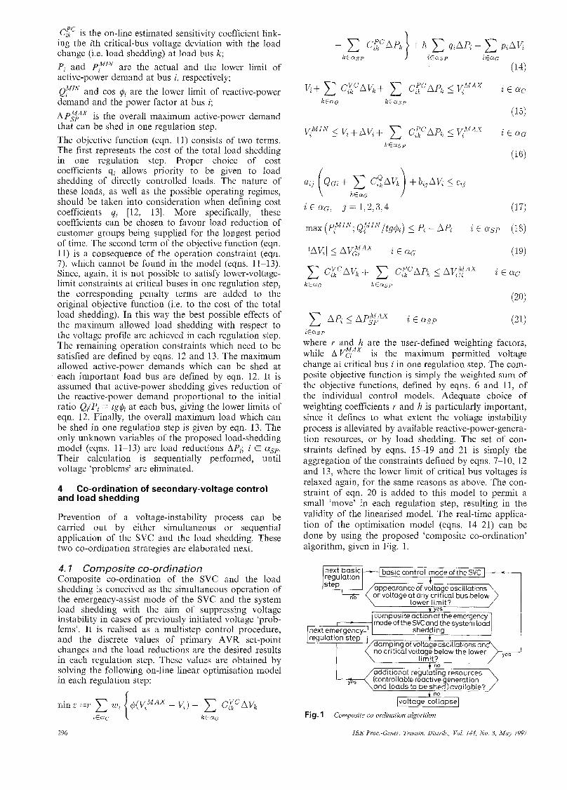
where Y and h are the user-defined weighting factors, while AVEAx is the maximum permitted voltage change at critical bus i in one regulation step. The com- posite objective function is simply the weighted sum of the objective functions, defined by eqns. 6 and 11, of the individual control models. Adequate choice of weighting coefficients r and h is particularly important, since it defines to what extent the voltage instability process is alleviated by available reactive-power-genera- tion resources, or by load shedding. The set of con- straints defined by eqns. 15-19 and 21 is simply the aggregation of the constraints defined by eqns. 7-10, 12 and 13, where the lower limit of critical bus voltages is relaxed again, for the same reasons as above. The con- straint of eqn. 20 is added to this model to permit a small 'move' in each regulation step, resulting in the validity of the linearised model. The real-time applica- tion of the optimisation model (eqns. 14-21) can be done by using the proposed 'composite co-ordination' algorithm, given in Fig. 1.
f voltage at any crifical bus below lower limit?
t yes composite action of theemergency mode of the SVC and the system load
shedding t
, ..- additional regulating resources (controllable reactive generation
nd loads to beshed)available?
Fig. 1 Composite co-ordination algorithm
296 IEE Proc -Gener. Transm. Distrib., Vol. 144, No. 3, May 1997
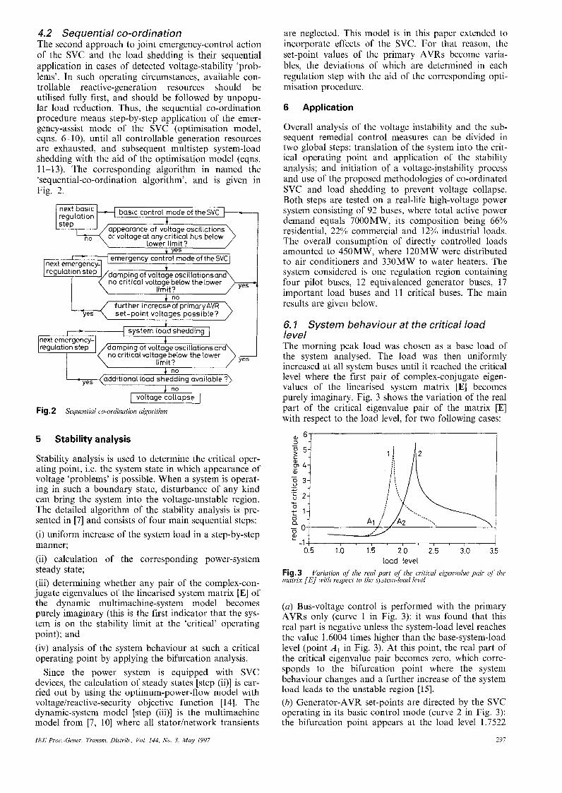
4.2 Sequential co-ordination The second approach to joint emergency-control action of the SVC and the load shedding is their sequential application in cases of detected voltage-stability ‘prob- lems,. In such operating circumstances, available con- trollable reactive-generation resources should be utilised fully first, and should be followed by unpopu- lar load reduction. Thus, the sequential co-ordination procedure means step-by-step application of the emer- gency-assist mode of the SVC (optimisation model, eqns. 6-1 O), until all controllable generation resources are exhausted, and subsequent multistep system-load shedding with the aid of the optimisation model (eqns. 11-13). The corresponding algorithm in named the ‘sequential-co-ordination algorithm’, and is given in Fig. 2.
regulation
appearance of voltage oscillations or voltageat any critical bus below
lower limit?
- 3- ,- + ._
. c - b 2- - b - 1- 0
a 5 0 F -
- 1 ,
, ,-- r = I emergency control mode of theSVCl
[next emergencd 1 I
, , , I , I I , I , ,
no further increaseof primary AVR
yes set-Doint voltaaes oossible? I c I
no
no
/
dditional load shedding available ?)
I voltagecollapse I Fig. 2 Sequential co-ordination algorithm
5 Stability analysis
Stability analysis is used to determine the critical oper- ating point, i.e. the system state in which appearance of voltage ‘problems’ is possible. When a system is operat- ing in such a boundary state, disturbance of any kind can bring the system into the voltage-unstable region. The detailed algorithm of the stability analysis is pre- sented in [7] and consists of four main sequential steps: (i) uniform increase of the system load in a step-by-step manner; (ii) calculation of the corresponding power-system steady state; (iii) determining whether any pair of the complex-con- jugate eigenvalues of the linearised system matrix [E] of the dynamic multimachine-system model becomes purely imaginary (this is the first indicator that the sys- tem is on the stability limit at the ‘critical’ operating point); and (iv) analysis of the system behaviour at such a critical operating point by applying the bifurcation analysis.
Since the power system is equipped with SVC devices, the calculation of steady states [step ($1 is car- ried out by using the optimum-power-flow model with voltageireactive-security objective function [ 141. The dynamic-system model [step (iii)] is the multimachine model from [7, 101 where all statorinetwork transients
IEE ProcGmer . Transm. Distrib., Vol. 144, No. 3, May 1997
are neglected. This model is in this paper extended to incorporate effects of the SVC. For that reason, the set-point values of the primary AVRs become varia- bles, the deviations of which are determined in each regulation step with the aid of the corresponding opti- misation procedure.
6 Application
Overall analysis of the voltage instability and the sub- sequent remedial control measures can be divided in two global steps: translation of the system into the crit- ical operating point and application of the stability analysis; and initiation of a voltage-instability process and use of the proposed methodologies of co-ordinated SVC and load shedding to prevent voltage collapse. Both steps are tested on a real-life high-voltage power system consisting of 92 buses, where total active power demand equals 7000 MW, its composition being 66% residential, 22% commercial and 12% industrial loads. The overall consumption of directly controlled loads amounted to 450MW, where 120MW were distributed to air conditioners and 330MW to water heaters. The system considered is one regulation region containing four pilot buses, 12 equivalenced generator buses, 17 important load buses and 11 critical buses. The main results are given below.
6, I System behaviour at the critical load level The morning peak load was chosen as a base load of the system analysed. The load was then uniformly increased at all system buses until it reached the critical level where the first pair of complex-conjugate eigen- values of the linearised system matrix [E] becomes purely imaginary. Fig. 3 shows the variation of the real part of the critical eigenvalue pair of the matrix [E] with respect to the load level, for two following cases:
01 6 1 I
0.5 1.0 1.5 2.0 2.5 3.0 3.5 load level
Fig.3 matrix [E] with respect to the system-load level
Variation of the real part of the critical eigenvulue pair of the
(a) Bus-voltage control is performed with the primary AVRs only (curve 1 in Fig. 3): it was found that this real part is negative unless the system-load level reaches the value 1.6004 times higher than the base-system-load level (point A I in Fig. 3). At this point, the real part of the critical eigenvalue pair becomes zero, which corre- sponds to the bifurcation point where the system behaviour changes and a further increase of the system load leads to the unstable region [15]. (b) Generator-AVR set-points are directed by the SVC operating in its basic control mode (curve 2 in Fig. 3): the bifurcation point appears at the load level 1.7522
297
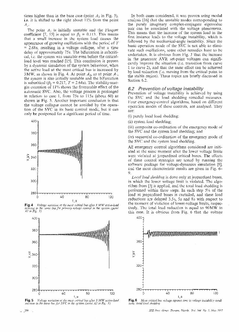
times higher than in the base case (point A2 in Fig. 3), i.e. it is shifted to the right about 11% from the point Al.
The point A, is initially unstable and the Floquet coefficient [7, 151 is equal to p2 = 0.113. This means that a small increase in the system load causes the appearance of growing oscillations with the period of T = 2.68s, resulting in a voltage collapse, after a time delay of approximately 75s. The bifurcation is subcriti- cal, i.e. the system was unstable even before the critical- load level was reached [15]. This conclusion is proven by a dynamic simulation of the system behaviour, when the active load at the most critical bus is increased by 3MW, as shown in Fig. 4. At point A,, as at point A I , the system is also initially unstable and the bifurcation is subcritical (a = 0.217, T = 2.64s). The stability-mar- gin extension of 11% shows the favourable effect of the automatic SVC. Also, the voltage process is prolonged in relation to case 1, from 75s to 115s (about 60) as shown in Fig. 5 . Another important conclusion is that the voltage collapse cannot be avoided by the opera- tion of the SVC in its basic control mode, but it can only be postponed for a significant period of time.
3804
360
>
> y. 340
3 ;-1 00
280 0 40 80 120
t,s Fig. 4 Voltage variation at the most critical bus after 3 MWactive-load increase in the same bus for primary-voltage control in the system (point A1 in Fig. 3)
400 zj
380
360
320
300
280 0 40 80 120
t,s Voltage variation at the most critical bus after 3 MWactive-load Fig.5
increase in the same bus for SVC in the system (point A2 in Fig. 3)
298
In both cases considered, it was proven using modal analysis [16] that the unstable modes corresponding to the purely imaginary complex-conjugate eigenvalue pair can be associated with the voltage phenomena. This means that the increase of the system load in the first instance leads to the voltage instability, which is followed by the mechanical-angle instability. Since the basic operation mode of the SVC is not able to elimi- nate such oscillations, some other remedies have to be undertaken. It is obvious from Fig. 3 that the increase in the generator AVR set-point voltages can signifi- cantly improve the situation (i.e. transition from curve 1 to curve 2), and that the same effect can be achieved by load reduction (i.e. moving from the critical point to the stable region). These topics are briefly discussed in Section 6.2.
6.2 Prevention of voltage instability Prevention of voltage instability is achieved by using the SVC and the load shedding remedial measures. Four emergency-control algorithms, based on different operation modes of these controls, are analysed. They are: (i) purely local load shedding; (ii) system load shedding; (iii) composite co-ordination of the emergency mode of the SVC and the system load shedding; and (iv) sequential co-ordination of the emergency mode of the SVC and the system load shedding. All emergency control algorithms considered are initi- ated at the same moment after the lower voltage limits were violated at jeopardised critical buses. The effects of these control strategies are tested by running the software package for voltage-dynamics simulation [8], and the most characteristic results are given in Fig. 6- 9.
Local load shedding is done only at jeopardised buses, in which the lower voltage limit is violated. The algo- rithm from [5] is applied, and the total load shedding is performed within three steps. In each step 5% of the load at jeopardised buses is curtailed, and these load reductions are delayed 3.5s, 5s and 8s with respect to the moment of violation of lower-voltage limits, respec- tively. The total load reduction is equal to 90MW in this case. It is obvious from Fig. 6 that the voltage
3604
320i 0 40 80 120
t , s Fig. 6 tions: local load shedding
Most critical bus voltage against time in voltage-instability condi-
IEE Proc.-Gener. Transm. Distuib., Vol. 144, No 3, May 1997
breakdown is avoided at the most critical bus, but the voltage instability is not eliminated since a new steady- state operating point cannot be established.
System load shedding is performed according to the proposed optimisation model (eqns. 11-13) in six sequential emergency-regulation steps. The maximum permitted load reduction A P g A X is set to 20MW in one regulation step. The total load reduction is 120MW in this case, which is a 33% increase compared with the local approach. The results given in Fig. 7 show that this is a more favourable situation than the first case, since the voltage instability is completely eliminated and a new stable steady state is reached after a time interval of 70s.
> x >- -
320- -,
4001
360-
> > *.
320-
-I
Composite co-ordination of the emergency mode of the SVC and the system load shedding is realised in five sequential emergency-regulation steps by running the proposed optimisation model (eqns. 14-21) within the composite co-ordination algorithm (Fig. 1). The maximum permitted AVR-set-point voltage increase A VEAx is set to 1 kV (0.25%), the maximum permitted voltage change at critical buses AVEAx is 1kV (0.25%), while the maximum load reduction APEAx is
360- 9
2 8 0 1 7 0 40 60 120
t.s Fig. 8 tions: composite co-ordination
Most critical bus voltage against time in voltage-instability condi-
set to 15MW in one regulation step. In this way, the total average voltage increase of generators participat- ing in the emergency SVC equals approximately 2.8kV (0.7%) and the total load reduction is 60MW, which is 33% less than in the case of the local-load-shedding approach. Owing to the composite action of the SVC and the load shedding, the system reaches a new stable steady state in less than 55s, while the voltage oscilla- tions during the transient period are significantly smaller than in cases of either the local, or the system approach to load shedding (Fig. 8).
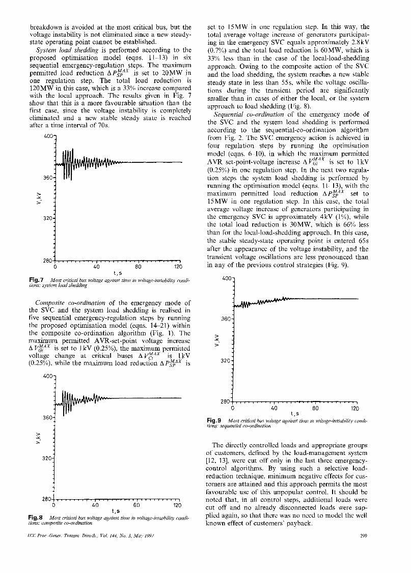
Sequential co-ordination of the emergency mode of the SVC and the system load shedding is performed according to the sequential-co-ordination algorithm from Fig. 2. The SVC emergency action is achieved in four regulation steps by running the optimisation model (eqns. 6-10), in which the maximum permitted AVR set-point-voltage increase A VgAX is set to 1 kV (0.25%) in one regulation step. In the next two regula- tion steps the system load shedding is performed by running the optimisation model (eqns. 11-13), with the maximum permitted load reduction APEAx set to 15MW in one regulation step. In this case, the total average voltage increase of generators participating in the emergency SVC is approximately 4kV (l%), while the total load reduction is 30MW, which is 66% less than for the local-load-shedding approach. In this case, the stable steady-state operating point is entered 65 s after the appearance of the voltage instability, and the transient voltage oscillations are less pronounced than in any of the previous control strategies (Fig. 9).
2 8 0 j j ~ 0 40 80 120
t , s Fig.9 tions: sequential co-ordination
Most critical bus voltage against time in voltage-instability condi-
The directly controlled loads and appropriate groups of customers, defined by the load-management system [12, 131, were cut off only in the last three emergency- control algorithms. By using such a selective load- reduction technique, minimum negative effects for cus- tomers are attained and this approach permits the most favourable use of this unpopular control. It should be noted that, in all control steps, additional loads were cut off and no already disconnected loads were sup- plied again, so that there was no need to model the well known effect of customers’ payback.
299 IEE Proc-Gener. Transm. Distrib.. Vol. 144, No. 3, May 1997

7 Conclusions
In this paper, emergency action of the secondary-volt- age control and the load shedding aimed at preventing voltage instability is investigated. Simulation results of a multimachine power system have shown that the sec- ondary- and the primary-voltage controls offer higher system loadability than the primary control only, but that neither of these two controls can eliminate an already initiated voltage-collapse process when operat- ing in the basic control mode. For this reason, the emergency-control mode of the secondary-voltage con- trol is developed, and it is followed by an analysis of the load-shedding techniques. The main attention is paid to the system approach to load shedding, leading to the proposed optimisation model. Next, the emer- gency-control mode of the secondary-voltage control and the system load shedding are combined to form the unified remedy, giving two control strategies which are summarised as the sequential and the composite emer- gency-control algorithms. Finally, the comparative analysis of these two emergency controls operating in voltage-instability conditions is performed by using four different algorithms: local and system approaches to the load shedding, as well as the composite and the sequential co-ordinated emergency action of the sec- ondary-voltage control and the system load shedding. The results show that proper co-ordination of these two emergency controls can prevent an already initi- ated voltage-collapse process efficiently, and that the corresponding transient processes have much better characteristics. Moreover, the generators participating in the emergency secondary-voltage control contribute significantly to reducing the overall curtailed load, giv- ing the economic benefits of the applied emergency- control policy. In that respect, the use of the proposed emergency-control algorithms decreases the risk of unplanned heavy load reductions and system blackout in cases of voltage emergency conditions.
8 References
1
2
‘Report on planning against voltage collapse’. CIGRE working group 38.01, task force 03, Paris, France, 1985 FINK, L.H. (ed): ‘Bulk power systems voltage phenomena - voltage stability and security’. Engineering Foundation Confer- ence, Potosi, USA, 1988, pp. 18-24
3 CLARK, H.K.: ‘New challenge: voltage stability’, IEEE Power Eng. Rev., 1990, 10, (4), pp. 33-37
4 BOURGIN, F., TESTUD, G., HEILBRONN, B., and VER- SEILLE, J.: ‘Present practices and trends on the French power system to prevent voltage collapse’, IEEE Trans., 1993, PWRS-8,
5 TAYLOR, C.W.: ‘Concepts of undervoltage load shedding for voltage stability’, IEEE Trans. Power Delivery, 1992, 7, (2), pp. 480488
6 KWATNY, H.G.: ‘Stability enhancement via secondary voltage regulation, in Bulk power systems voltage phenomena I1 - volt- age stability and security’. Engineering Foundation Conference, Deep Creek Lake, USA, 1991, pp. 147-156 POPOVIC D.S., and ’CALOVI’C; M.S.: ‘Secondary voltage con- trol and power system performance in case of voltage instability’, Rev. Gen. Elect., November 1994, 10, pp. 8-18 POPOVIC, D.S., and GORECAN, Z.A.: ‘VOCODYS - soft- ware package for voltage control dynamics simulation within bulk power systems’. Final report, University of Novi Sad, School of Engineering Sciences, Yugoslavia, 1992
9 PAUL, J.P., CORROYER, C., JEANNEL, P., TESSERON, J.M., MAURY, F., and TORRA, A.: ‘Improvements in the organization of secondary voltage control in France’. CIGRE Rapport, Paris, 1990, No. 38/39-03
I O RAJAGOPALAN, C., LESIEUTRE, B., SAUER, P.W., and PAI, M.A.: ‘Dynamic aspects of voltage/power characteristics’, IEEE Trans., 1992, PWRS-7, (3), pp. 990-1000
11 PAUL, J.P.: ‘Electricite De France current practice of voltage control, In Bulk power systems voltage phenomena ~ voltage stability and security’. Paper 4-2, Engineering Foundation Con- ference, Potosi. USA, 1988
(3), pp. 778-788
7
8
12 TALUKDAR, S., and GELLINGS, C.W.: ‘Load management’ (IEEE, New York, 1987)
13 HSU, Y.Y., and SU, C.C.: ‘Dispatch of direct load control using dynamic programming’, IEEE Trans., 1991, PWRS-6, (3), pp. 1056-1061
14 POPOVIC D.S., and ’CALOVI’C, M.S., and LEVI, V.A.: ‘Volt- ageireactive security analysis in power system with automatic sec- ondary voltage control’, IEE Proc. Gen. Transnz. Distrib., 1994,
15 SEYDEL, R.: ‘From equilibrium to chaos - practical bifurcation and stability analysis’ (Elsevier Science Publishing Co., New York, 1988)
16 PEREZ-ARRIAGA, I.J., VERGHESE, G.C., and SHWEP- PE, F.C.: ‘Selective modal analysis with applications to electric power system, Parts I and 11’, IEEE Trans., 1982, PAS-101, (9), pp. 3117-3134
141, (3), pp. 177-183
300 IEE Proc-Gener. Tvansm Distrib., Vol. 144, No. 3, May 1997