cng fuel system시안7 - viking...
TRANSCRIPT

Products and Custom Solutions

Parker Hannifin is the country's leader in designing and manufacturing products fordelivering compressed(CNG) and Liguified Natural Gas(LNG). Parker makes the mostcomplete products package for handling CNG including fittings, filters, couplings, valves,hoses, nozzles and receptacle. Parker's development of new technologies and steadygrowth in established markets have made Parker Hannifin a global leader in motion andcontrol.
NATURAL GAS VEHICLE

CNGPRODUCTS
CNGPRODUCTS
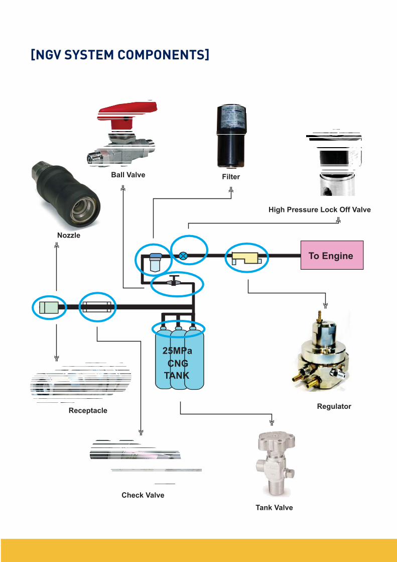
To Engine
Ball Valve
25MPa
CNG
TANK
Nozzle
Receptacle
Check Valve
Regulator
Filter
High Pressure Lock Off Valve
Tank Valve
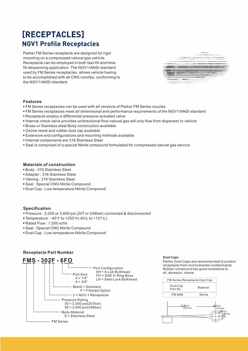
FMS - 302F - 6FO
Port ConfigurationAH = A-Lok BulkheadFO = SAE O-Ring BossLH = Seal-Lock Bulkhead
Port Size4 = 1/4"6 = 3/8"
Blank = StandardF = Filtered Option
2 = NGV-1 Receptacle
Pressure Rating30 = 3,000 psi(207bar)36 = 3,600 psi(248bar)
Body MaterialS = Stainless Steel
FM Series
Parker FM Series receptacle are designed for rigid
mounting on a compressed natural gas vehicle.
Receptacle can be employed in both fast-fill and time-
fill despensing application. The NGV1/ANSI standard
used by FM Series receptacles, allows vehicle fueling
to be accomplished with all CNG nozzles, conforming to
the NGV1/ANSI standard.
FM Series receptacles can be used with all versions of Parker FM Series nozzles
FM Series receptacles meet all dimensional and performance requirements of the NGV1/ANSI standard
Receptacle employ a differential pressure-actuated valve
Internal check valve provides unidrectional flow-natural gas will only flow from dispenser to vehicle
Brass or Stainless steel Body construction available
Ozone resist and rubber dust cap available
Extensive end configurations and mounting methods available
Internal components are 316 Stainless Steel
Seal is comprised of a special Nitrile compound formulated for compressed natural gas service
Body : 316 Stainless Steel
Adapter : 316 Stainless Steel
Valving : 316 Stainless Steel
Seal : Special CNG Nitrile Compound
Dust Cap : Low temperature Nitrile Compound
Pressure : 3,000 or 3,600 psi (207 or 248bar) connected & disconnected
Temperature : -40 to +250 (-40 to +121 )
Rated Flow : 1,500 scfm
Seal : Special CNG Nitrile Compound
Dust Cap : Low temperature Nitrile Compound
Features
Materials of construction
Specification
Receptacle Part NumberDust Caps
Parker Dust Caps are recommended to protectreceptacle from invironmental contaminants.Rubber compound has good resistance tooil, abrasion, ozone.
FM Series Receptacle Dust Cap
Dust CapPart No.
Material
FM-66M Nitrile
6.30 in.(160 mm)
.850 in.(22 mm)
.200 in.(5 mm)
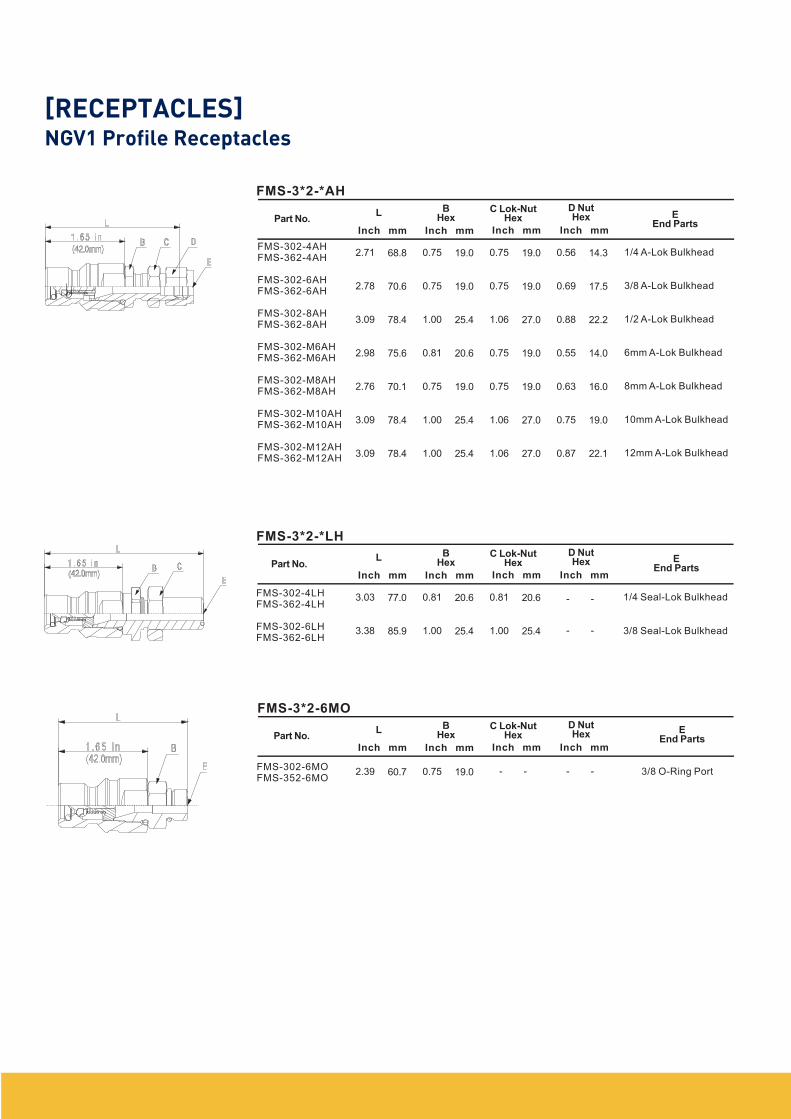
Part No.B
HexL
FMS-302-4AHFMS-362-4AH
FMS-302-6AHFMS-362-6AH
FMS-302-8AHFMS-362-8AH
FMS-302-M6AHFMS-362-M6AH
FMS-302-M8AHFMS-362-M8AH
FMS-302-M10AHFMS-362-M10AH
FMS-302-M12AHFMS-362-M12AH
2.71
2.78
3.09
2.98
2.76
3.09
3.09
FMS-3*2-*AH
C Lok-NutHex
D NutHex E
End Parts
1/4 A-Lok Bulkhead
3/8 A-Lok Bulkhead
1/2 A-Lok Bulkhead
6mm A-Lok Bulkhead
8mm A-Lok Bulkhead
10mm A-Lok Bulkhead
12mm A-Lok Bulkhead
FMS-302-4LHFMS-362-4LH
FMS-302-6LHFMS-362-6LH
FMS-3*2-*LH
1/4 Seal-Lok Bulkhead
3/8 Seal-Lok Bulkhead
FMS-302-6MOFMS-352-6MO
FMS-3*2-6MO
3/8 O-Ring Port
Inch mm
68.8
70.6
78.4
75.6
70.1
78.4
78.4
0.75
0.75
1.00
0.81
0.75
1.00
1.00
19.0
19.0
25.4
20.6
19.0
25.4
25.4
0.75
0.75
1.06
0.75
0.75
1.06
1.06
19.0
19.0
27.0
19.0
19.0
27.0
27.0
0.56
0.69
0.88
0.55
0.63
0.75
0.87
14.3
17.5
22.2
14.0
16.0
19.0
22.1
Inch mm Inch mm Inch mm
Part No.B
HexL C Lok-Nut
HexD NutHex E
End PartsInch mm Inch mm Inch mm Inch mm
Part No.B
HexL C Lok-Nut
HexD NutHex E
End PartsInch mm Inch mm Inch mm Inch mm
3.03
3.38
77.0
85.9
0.81
1.00
20.6
25.4
0.81
1.00
20.6
25.4
2.39 0.7560.7 19.0
- -
- -
- -- -
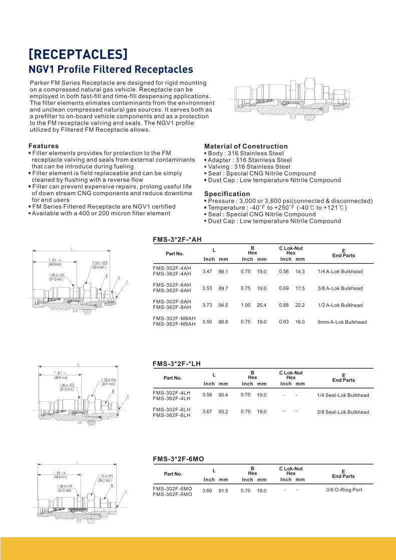
Parker FM Series Receptacle are designed for rigid mountingon a compressed natural gas vehicle. Receptacle can beemployed in both fast-fill and time-fill despensing applications.The filter elements elimates contaminants from the environmentand unclean compressed natural gas sources. It serves both asa prefilter to on-board vehicle components and as a protectionto the FM receptacle valving and seals. The NGV1 profileutilized by Filtered FM Receptacle allows.
FeaturesFilter elements provides for protection to the FMreceptacle valving and seals from external contaminantsthat can be introduce during fuelingFilter element is field replaceable and can be simplycleaned by flushing with a reverse flowFilter can prevent expensive repairs, prolong useful lifeof down stream CNG components and reduce downtimefor end usersFM Series Filtered Receptacle are NGV1 certifiedAvailable with a 400 or 200 micron filter element
Material of Construction
Specification
Body : 316 Stainless SteelAdapter : 316 Stainless SteelValving : 316 Stainless SteelSeal : Special CNG Nitrile CompoundDust Cap : Low temperature Nitrile Compound
Pressure : 3,000 or 3,600 psi(connected & disconnected)Temperature : -40 to +250 (-40 to +121 )Seal : Special CNG Nitrile CompoundDust Cap : Low temperature Nitrile Compound
FMS-302F-4AHFMS-362F-4AH
FMS-302F-6AHFMS-362F-6AH
FMS-302F-8AHFMS-362F-8AH
FMS-302F-M8AHFMS-362F-M8AH
FMS-3*2F-*AH
1/4 A-Lok Bulkhead
3/8 A-Lok Bulkhead
1/2 A-Lok Bulkhead
8mm A-Lok Bulkhead
FMS-302F-4LHFMS-362F-4LH
FMS-302F-6LHFMS-362F-6LH
1/4 Seal-Lok Bulkhead
3/8 Seal-Lok Bulkhead
FMS-302F-6MOFMS-362F-6MO
FMS-3*2F-6MO
3/8 O-Ring Port
Part No.B
HexL
3.47
3.53
3.73
3.50
C Lok-NutHex E
End PartsInch mm
88.1
89.7
94.5
88.8
0.75
0.75
1.00
0.75
19.0
19.0
25.4
19.0
0.56
0.69
0.88
0.63
14.3
17.5
22.2
16.0
Inch mm Inch mm
FMS-3*2F-*LH
Part No.B
HexL
3.56
3.67
C Lok-NutHex E
End PartsInch mm
90.4
93.2
0.75
0.75
19.0
19.0
Inch mm Inch mm
Part No.B
HexL
3.60
C Lok-NutHex E
End PartsInch mm
91.5 0.75 19.0
Inch mm Inch mm
- -
- -
- -
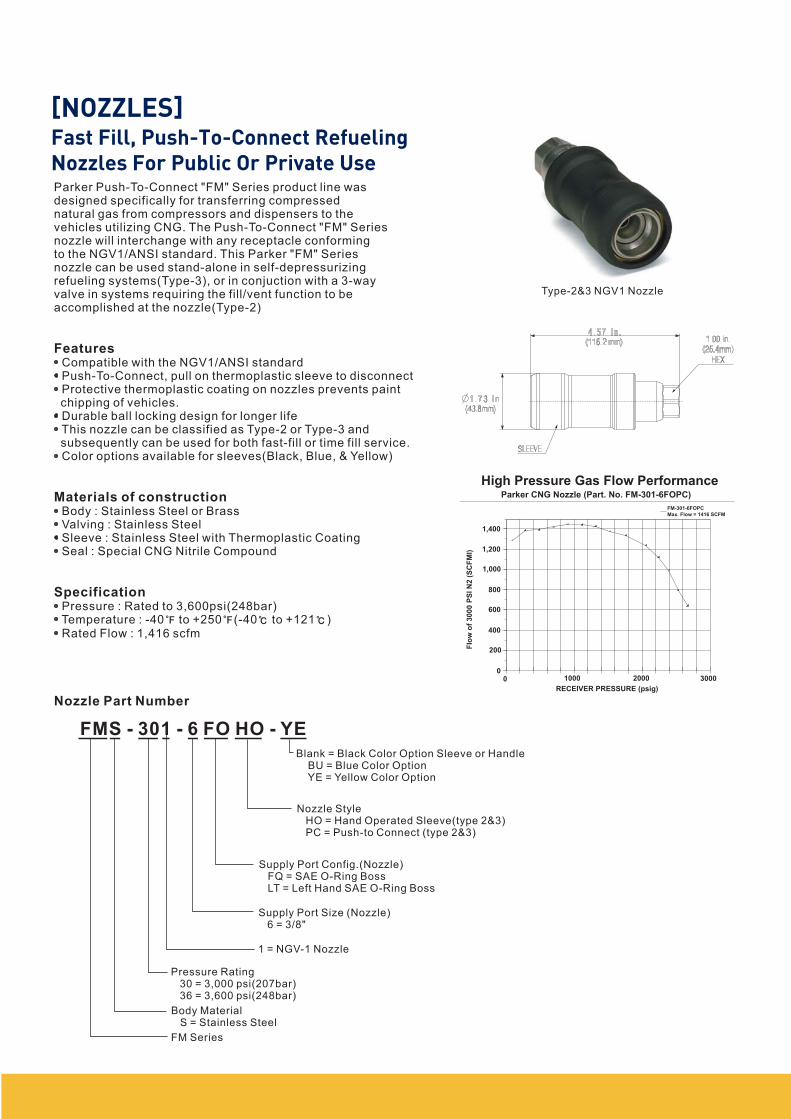
Parker Push-To-Connect "FM" Series product line wasdesigned specifically for transferring compressednatural gas from compressors and dispensers to thevehicles utilizing CNG. The Push-To-Connect "FM" Seriesnozzle will interchange with any receptacle conformingto the NGV1/ANSI standard. This Parker "FM" Seriesnozzle can be used stand-alone in self-depressurizingrefueling systems(Type-3), or in conjuction with a 3-wayvalve in systems requiring the fill/vent function to beaccomplished at the nozzle(Type-2)
Compatible with the NGV1/ANSI standardPush-To-Connect, pull on thermoplastic sleeve to disconnectProtective thermoplastic coating on nozzles prevents paintchipping of vehicles.Durable ball locking design for longer lifeThis nozzle can be classified as Type-2 or Type-3 andsubsequently can be used for both fast-fill or time fill service.Color options available for sleeves(Black, Blue, & Yellow)
Body : Stainless Steel or BrassValving : Stainless SteelSleeve : Stainless Steel with Thermoplastic CoatingSeal : Special CNG Nitrile Compound
Pressure : Rated to 3,600psi(248bar)Temperature : -40 to +250 (-40 to +121 )Rated Flow : 1,416 scfm
Features
Materials of construction
Specification
Nozzle Part Number
FMS - 301 - 6 FO HO - YE
Blank = Black Color Option Sleeve or HandleBU = Blue Color OptionYE = Yellow Color Option
Nozzle StyleHO = Hand Operated Sleeve(type 2&3)PC = Push-to Connect (type 2&3)
Supply Port Config.(Nozzle)FQ = SAE O-Ring BossLT = Left Hand SAE O-Ring Boss
Supply Port Size (Nozzle)6 = 3/8"
1 = NGV-1 Nozzle
Pressure Rating30 = 3,000 psi(207bar)36 = 3,600 psi(248bar)
FM Series
Type-2&3 NGV1 Nozzle
High Pressure Gas Flow PerformanceParker CNG Nozzle (Part. No. FM-301-6FOPC)
Flo
wo
f3
00
0P
SIN
2(S
CF
MI)
1,400
1,200
1,000
800
600
400
200
00 1000 2000 3000
RECEIVER PRESSURE (psig)
FM-301-6FOPC
Max. Flow = 1416 SCFM
Body MaterialS = Stainless Steel
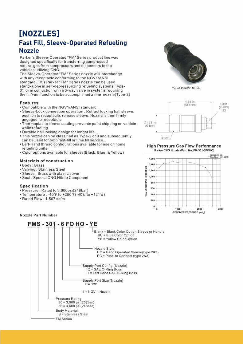
Type-2&3 NGV1 Nozzle
Parker's Sleeve-Operated "FM" Series product line wasdesigned specifically for transferring compressednatural gas from compressors and dispensers to thevehicles utilizing CNG.The Sleeve-Operated "FM" Series nozzle will interchangewith any receptacle conforming to the NGV1/ANSIstandard. This Parker "FM" Series nozzle can be usedstand-alone in self-depressurizing refueling systems(Type-3), or in conjuction with a 3-way valve in systems requiringthe fill/vent function to be accomplished at the nozzle(Type-2)
Compatible with the NGV1/ANSI standardSleeve-Lock connection operation : Retract locking ball sleeve,push on to receptacle, release sleeve. Nozzle is then firmlygngaged to receptacleThermoplasitc sleeve coating prevents paint chipping on vehiclewhile refuelingDurable ball locking design for longer lifeThis nozzle can be classified as Type-2 or 3 and subsequentlycan be used for both fast-fill or time fill service.Left-Hand thread configurations available for use on homerefueling unitsColor options available for sleeves(Black, Blue, & Yellow)
Body : BrassValving : Stainless SteelSleeve : Brass with plastic coverSeal : Special CNG Nitrile Compound
Pressure : Rated to 3,600psi(248bar)Temperature : -40 to +250 (-40 to +121 )Rated Flow : 1,507 scfm
Features
Materials of construction
Specification
Nozzle Part Number
High Pressure Gas Flow PerformanceParker CNG Nozzle (Part. No. FM-301-6FOHO)
Flo
wo
f3
00
0P
SI
N2
(SC
FM
I)
1,600
1,400
1,200
1,000
800
600
400
200
0
0 1000 2000 3000
RECEIVER PRESSURE (psig)
FM-301-6FOHO
Max. Flow = 1507 SCFM
FMS - 301 - 6 FO HO - YE
Blank = Black Color Option Sleeve or HandleBU = Blue Color OptionYE = Yellow Color Option
Nozzle StyleHO = Hand Operated Sleeve(type 2&3)PC = Push-to Connect (type 2&3)
Supply Port Config.(Nozzle)FQ = SAE O-Ring BossLT = Left Hand SAE O-Ring Boss
Supply Port Size (Nozzle)6 = 3/8"
1 = NGV-1 Nozzle
Pressure Rating30 = 3,000 psi(207bar)36 = 3,600 psi(248bar)
FM Series
Body MaterialS = Stainless Steel
Part No. ServicePressuerMaterial
AcceptsReceptacles End Parts
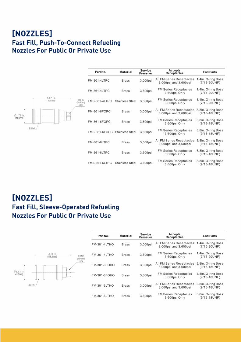
FM-301-4LTPC
FM-361-4LTPC
FMS-361-4LTPC
FM-301-6FOPC
FM-361-6FOPC
FMS-361-6FOPC
FM-301-6LTPC
FM-361-6LTPC
FMS-361-6LTPC
Brass
Brass
Stainless Steel
Brass
Brass
Stainless Steel
Brass
Brass
Stainless Steel
3,000psi
3,600psi
3,600psi
3,000psi
3,600psi
3,600psi
3,000psi
3,600psi
3,600psi
All FM Series Receptacles3,000psi and 3,600psi
FM Series Receptacles3,600psi Only
FM Series Receptacles3,600psi Only
All FM Series Receptacles3,000psi and 3,600psi
FM Series Receptacles3,600psi Only
FM Series Receptacles3,600psi Only
All FM Series Receptacles3,000psi and 3,600psi
FM Series Receptacles3,600psi Only
FM Series Receptacles3,600psi Only
1/4in. O-ring Boss(7/16-20UNF)
1/4in. O-ring Boss(7/16-20UNF)
1/4in. O-ring Boss(7/16-20UNF)
3/8in. O-ring Boss(9/16-18UNF)
3/8in. O-ring Boss(9/16-18UNF)
3/8in. O-ring Boss(9/16-18UNF)
3/8in. O-ring Boss(9/16-18UNF)
3/8in. O-ring Boss(9/16-18UNF)
3/8in. O-ring Boss(9/16-18UNF)
FM-301-4LTHO
FM-361-4LTHO
FM-301-6FOHO
FM-361-6FOHO
FM-301-6LTHO
FM-361-6LTHO
Brass
Brass
Brass
Brass
Brass
Brass
3,000psi
3,600psi
3,000psi
3,600psi
3,000psi
3,600psi
All FM Series Receptacles3,000psi and 3,600psi
FM Series Receptacles3,600psi Only
All FM Series Receptacles3,000psi and 3,600psi
FM Series Receptacles3,600psi Only
All FM Series Receptacles3,000psi and 3,600psi
FM Series Receptacles3,600psi Only
1/4in. O-ring Boss(7/16-20UNF)
1/4in. O-ring Boss(7/16-20UNF)
3/8in. O-ring Boss(9/16-18UNF)
3/8in. O-ring Boss(9/16-18UNF)
3/8in. O-ring Boss(9/16-18UNF)
3/8in. O-ring Boss(9/16-18UNF)
Part No.Service
PressuerMaterialAccepts
Receptacles End Parts
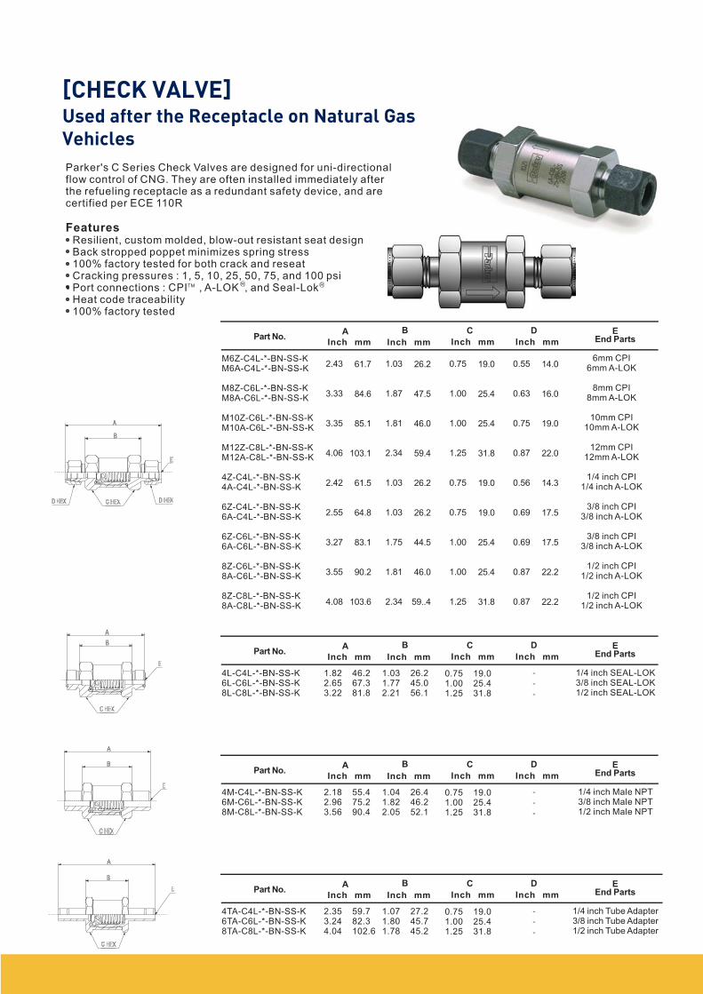
Parker's C Series Check Valves are designed for uni-directionalflow control of CNG. They are often installed immediately afterthe refueling receptacle as a redundant safety device, and arecertified per ECE 110R
Resilient, custom molded, blow-out resistant seat designBack stropped poppet minimizes spring stress100% factory tested for both crack and reseatCracking pressures : 1, 5, 10, 25, 50, 75, and 100 psiPort connections : CPI , A-LOK , and Seal-LokHeat code traceability100% factory tested
Features
M6Z-C4L-*-BN-SS-KM6A-C4L-*-BN-SS-K
M8Z-C6L-*-BN-SS-KM8A-C6L-*-BN-SS-K
M10Z-C6L-*-BN-SS-KM10A-C6L-*-BN-SS-K
M12Z-C8L-*-BN-SS-KM12A-C8L-*-BN-SS-K
4Z-C4L-*-BN-SS-K4A-C4L-*-BN-SS-K
6Z-C4L-*-BN-SS-K6A-C4L-*-BN-SS-K
6Z-C6L-*-BN-SS-K6A-C6L-*-BN-SS-K
8Z-C6L-*-BN-SS-K8A-C6L-*-BN-SS-K
8Z-C8L-*-BN-SS-K8A-C8L-*-BN-SS-K
6mm CPI6mm A-LOK
8mm CPI8mm A-LOK
10mm CPI10mm A-LOK
12mm CPI12mm A-LOK
1/4 inch CPI1/4 inch A-LOK
3/8 inch CPI3/8 inch A-LOK
3/8 inch CPI3/8 inch A-LOK
1/2 inch CPI1/2 inch A-LOK
1/2 inch CPI1/2 inch A-LOK
TM R R
Part No.BA
2.43
3.33
3.35
4.06
2.42
2.55
3.27
3.55
4.08
C D EEnd PartsInch mm
61.7
84.6
85.1
103.1
61.5
64.8
83.1
90.2
103.6
1.03
1.87
1.81
2.34
1.03
1.03
1.75
1.81
2.34
26.2
47.5
46.0
59.4
26.2
26.2
44.5
46.0
59..4
0.75
1.00
1.00
1.25
0.75
0.75
1.00
1.00
1.25
19.0
25.4
25.4
31.8
19.0
19.0
25.4
25.4
31.8
0.55
0.63
0.75
0.87
0.56
0.69
0.69
0.87
0.87
14.0
16.0
19.0
22.0
14.3
17.5
17.5
22.2
22.2
Inch mm Inch mm Inch mm
4L-C4L-*-BN-SS-K6L-C6L-*-BN-SS-K8L-C8L-*-BN-SS-K
1/4 inch SEAL-LOK3/8 inch SEAL-LOK1/2 inch SEAL-LOK
Part No.BA C D E
End PartsInch mm Inch mm Inch mm Inch mm
1.822.653.22
46.267.381.8
1.031.772.21
26.245.056.1
0.751.001.25
19.025.431.8
4M-C4L-*-BN-SS-K6M-C6L-*-BN-SS-K8M-C8L-*-BN-SS-K
1/4 inch Male NPT3/8 inch Male NPT1/2 inch Male NPT
Part No.BA C D E
End PartsInch mm Inch mm Inch mm Inch mm
2.182.963.56
55.475.290.4
1.041.822.05
26.446.252.1
0.751.001.25
19.025.431.8
4TA-C4L-*-BN-SS-K6TA-C6L-*-BN-SS-K8TA-C8L-*-BN-SS-K
1/4 inch Tube Adapter3/8 inch Tube Adapter1/2 inch Tube Adapter
Part No.BA C D E
End PartsInch mm Inch mm Inch mm Inch mm
2.353.244.04
59.782.3102.6
1.071.801.78
27.245.745.2
0.751.001.25
19.025.431.8
-
-
-
-
-
-
-
-
-
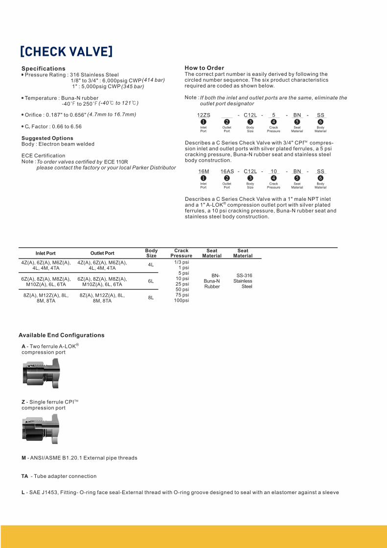
Pressure Rating : 316 Stainless Steel1/8" to 3/4" : 6,000psig CWP1" : 5,000psig CWP
Temperature : Buna-N rubber-40 to 250
Orifice : 0.187" to 0.656"
C Factor : 0.66 to 6.56
Body : Electron beam welded
ECE CertificationNote :
Specifications
Suggested Options
(414 bar)
(345 bar)
(-40 to 121 )
(4.7mm to 16.7mm)
V
To order valves certified byplease contact the factory or your local Parker Distributor
ECE 110R
How to OrderThe correct part number is easily derived by following thecircled number sequence. The six product characteristicsrequired are coded as shown below.
Note : If both the inlet and outlet ports are the same, eliminate theoutlet port designator
Describes a C Series Check Valve with 3/4" CPI compres-sion inlet and outlet ports with silver plated ferrules, a 5 psicracking pressure, Buna-N rubber seat and stainless steelbody construction.
Describes a C Series Check Valve with a 1" male NPT inletand a 1" A-LOK compression outlet port with silver platedferrules, a 10 psi cracking pressure, Buna-N rubber seat andstainless steel body construction.
TM
R
Available End Configurations
A - Two ferrule A-LOKcompression port
M - ANSI/ASME B1.20.1 External pipe threads
L - SAE J1453, Fitting- O-ring face seal-External thread with O-ring groove designed to seal with an elastomer against a sleeve
Z - Single ferrule CPIcompression port
TA - Tube adapter connection
R
1 2 3 4 5 6
12ZS - C12L - - BN -5 SS
InletPort
OutletPort
BodySize
CrackPressure
SeatMaterial
BodyMaterial
1 2 3 4 5 6
16M - C12L - - BN -10 SS
InletPort
OutletPort
BodySize
CrackPressure
SeatMaterial
BodyMaterial
16AS
Inlet Port
4Z(A), 6Z(A), M6Z(A),4L, 4M, 4TA
6Z(A), 8Z(A), M8Z(A),M10Z(A), 6L, 6TA
8Z(A), M12Z(A), 8L,8M, 8TA
4L
6L
8L
CrackPressure
1/3 psi1 psi5 psi
10 psi25 psi50 psi75 psi
100psi
4Z(A), 6Z(A), M6Z(A),4L, 4M, 4TA
6Z(A), 8Z(A), M8Z(A),M10Z(A), 6L, 6TA
8Z(A), M12Z(A), 8L,8M, 8TA
Outlet PortBodySize
SeatMaterial
SeatMaterial
BN-Buna-NRubber
SS-316Stainless
Steel
TM
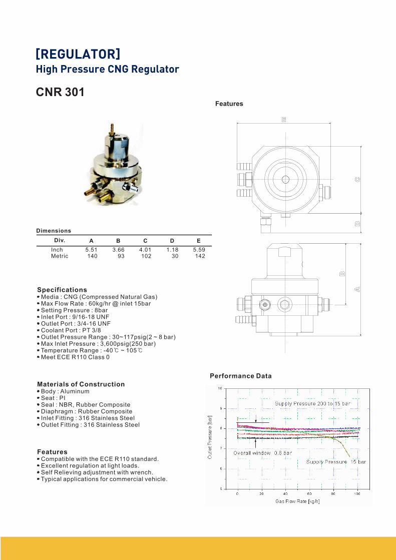
CNR 301
Dimensions
Div. A B C D E
InchMetric
5.51140
3.6693
4.01102
1.1830
5.59142
Media : CNG (Compressed Natural Gas)Max Flow Rate : 60kg/hr @ inlet 15barSetting Pressure : 8barInlet Port : 9/16-18 UNFOutlet Port : 3/4-16 UNFCoolant Port : PT 3/8Outlet Pressure Range : 30~117psig(2 ~ 8 bar)Max Inlet Pressure : 3,600psig(250 bar)Temperature Range : -40 ~ 105Meet ECE R110 Class 0
Body : AluminumSeat : PISeal : NBR, Rubber CompositeDiaphragm : Rubber CompositeInlet Fitting : 316 Stainless SteelOutlet Fitting : 316 Stainless Steel
Compatible with the ECE R110 standard.Excellent regulation at light loads.Self Relieving adjustment with wrench.Typical applications for commercial vehicle.
Specifications
Materials of Construction
Features
Performance Data
Features
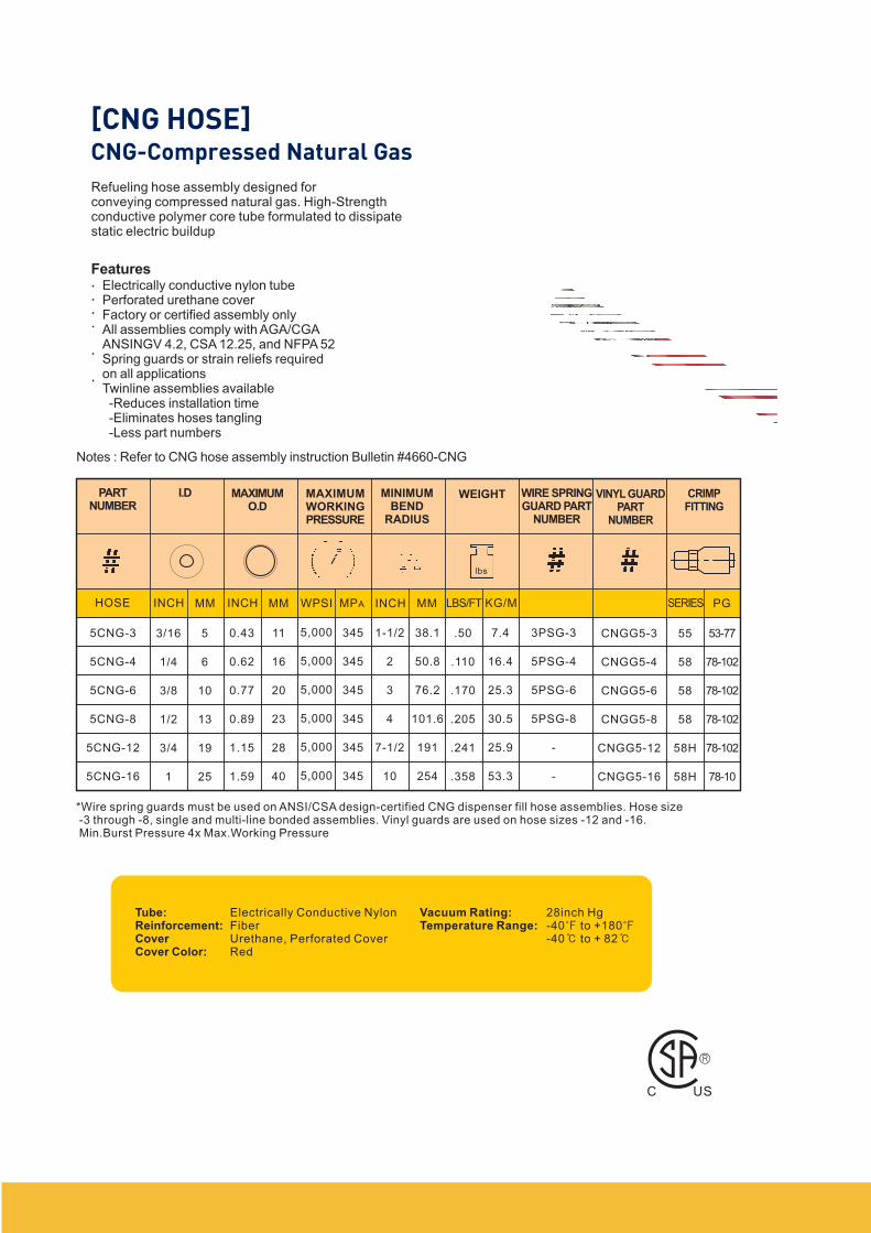
Refueling hose assembly designed forconveying compressed natural gas. High-Strengthconductive polymer core tube formulated to dissipatestatic electric buildup
FeaturesElectrically conductive nylon tubePerforated urethane coverFactory or certified assembly onlyAll assemblies comply with AGA/CGAANSINGV 4.2, CSA 12.25, and NFPA 52Spring guards or strain reliefs requiredon all applicationsTwinline assemblies available-Reduces installation time-Eliminates hoses tangling-Less part numbers
Notes : Refer to CNG hose assembly instruction Bulletin #4660-CNG
.
.
.
.
.
.
PARTNUMBER
I.D MAXIMUMO.D
WEIGHT WIRE SPRINGGUARD PART
NUMBER
VINYL GUARDPART
NUMBER
MAXIMUMWORKINGPRESSURE
MINIMUMBEND
RADIUS
CRIMPFITTING
HOSE INCH MM WPSI MPA INCH MM LBS/FT KG/MINCH MM SERIES PG
5CNG-3
5CNG-4
5CNG-6
5CNG-8
5CNG-12
5CNG-16
3/16
1/4
3/8
1/2
3/4
1
5
6
10
13
19
25
0.43
0.62
0.77
0.89
1.15
1.59
11
16
20
23
28
40
5,000
5,000
5,000
5,000
5,000
5,000
345
345
345
345
345
345
1-1/2
2
3
4
7-1/2
10
38.1
50.8
76.2
101.6
191
254
.50
.110
.170
.205
.241
.358
7.4
16.4
25.3
30.5
25.9
53.3
3PSG-3
5PSG-4
5PSG-6
5PSG-8
-
-
CNGG5-3
CNGG5-4
CNGG5-6
CNGG5-8
CNGG5-12
CNGG5-16
55
58
58
58
58H
58H
53-77
78-102
78-102
78-102
78-102
78-10
*Wire spring guards must be used on ANSI/CSA design-certified CNG dispenser fill hose assemblies. Hose size-3 through -8, single and multi-line bonded assemblies. Vinyl guards are used on hose sizes -12 and -16.Min.Burst Pressure 4x Max.Working Pressure
Tube:Reinforcement:CoverCover Color:
Electrically Conductive NylonFiberUrethane, Perforated CoverRed
Vacuum Rating:Temperature Range:
28inch Hg-40 to +180-40 to + 82
lbs
C US
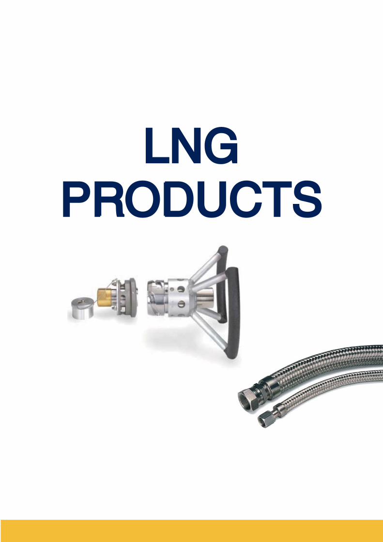
LNGPRODUCTS
LNGPRODUCTS
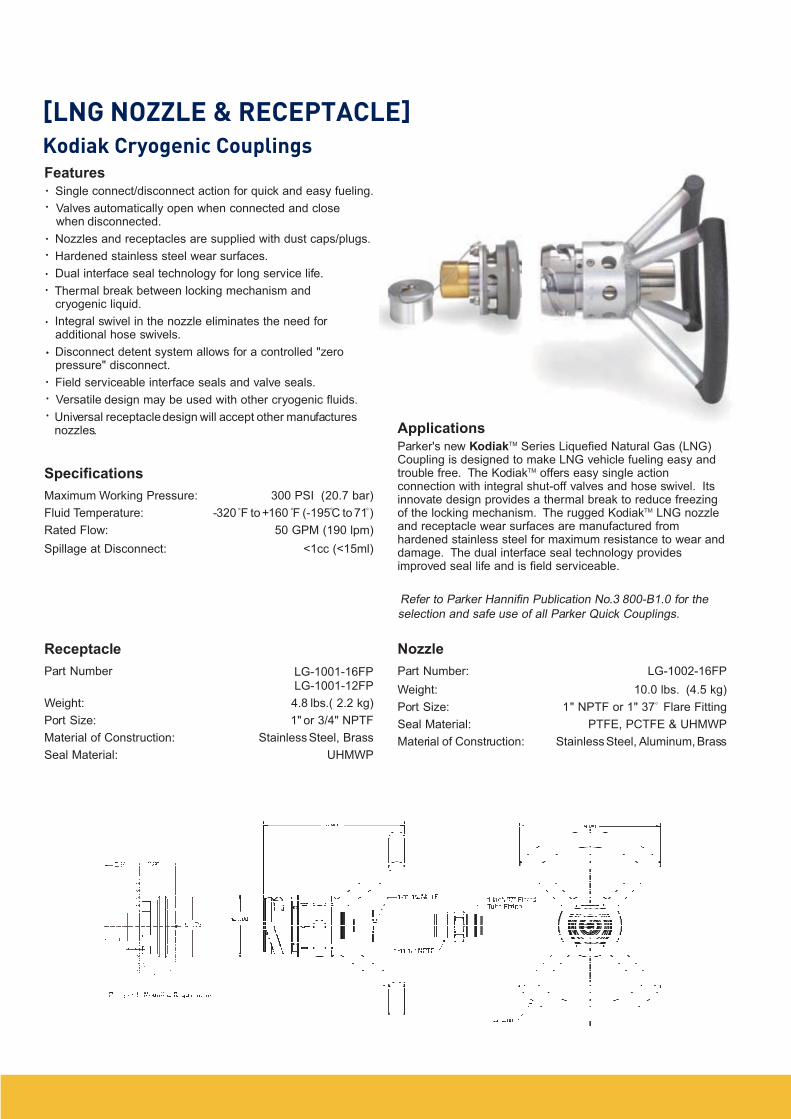
Features
Single connect/disconnect action for quick and easy fueling.
Valves automatically open when connected and closewhen disconnected.
Nozzles and receptacles are supplied with dust caps/plugs.
Hardened stainless steel wear surfaces.
Dual interface seal technology for long service life.
Thermal break between locking mechanism andcryogenic liquid.
Integral swivel in the nozzle eliminates the need foradditional hose swivels.
Disconnect detent system allows for a controlled "zeropressure" disconnect.
Field serviceable interface seals and valve seals.
Versatile design may be used with other cryogenic fluids.
Universal receptacledesign will accept other manufacturesnozzles.
Specifications
Maximum Working Pressure: 300 PSI (20.7 bar)
Fluid Temperature: -320 F to+160 F (-195C to71 )
Rated Flow: 50 GPM (190 lpm)
Spillage at Disconnect: <1cc (<15ml)
Receptacle
Part Number LG-1001-16FPLG-1001-12FP
Weight: 4.8 lbs.( 2.2 kg)
Port Size: 1" or 3/4" NPTF
Material of Construction: StainlessSteel, Brass
Seal Material: UHMWP
Applications
Parker's new KodiakTM Series Liquefied Natural Gas (LNG)Coupling is designed to make LNG vehicle fueling easy andtrouble free. The KodiakTM offers easy single actionconnection with integral shut-off valves and hose swivel. Itsinnovate design provides a thermal break to reduce freezingof the locking mechanism. The rugged KodiakTM LNG nozzleand receptacle wear surfaces are manufactured fromhardened stainless steel for maximum resistance to wear anddamage. The dual interface seal technology providesimproved seal life and is field serviceable.
Refer to Parker Hannifin Publication No.3 800-B1.0 for the
selection and safe use of all Parker Quick Couplings.
Nozzle
Part Number: LG-1002-16FP
Weight: 10.0 lbs. (4.5 kg)
Port Size: 1" NPTF or 1" 37 Flare Fitting
Seal Material: PTFE, PCTFE & UHMWP
Material of Construction: StainlessSteel, Aluminum, Brass
.
o o o o
o
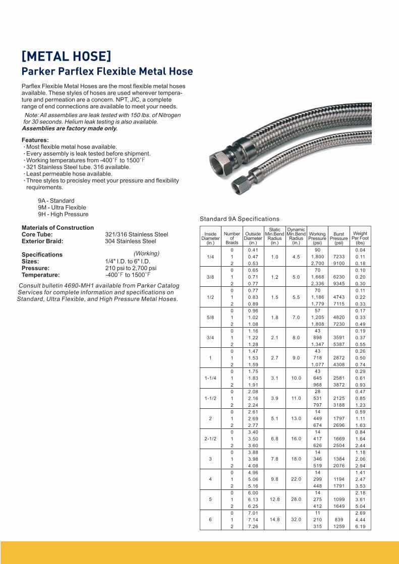
Parflex Flexible Metal Hoses are the most flexible metal hosesavailable. These styles of hoses are used wherever tempera-ture and permeation are a concern. NPT, JIC, a completerange of end connections are available to meet your needs.
Most flexible metal hose available.Every assembly is leak tested before shipment.Working temperatures from -400 to 1500321 Stainless Steel tube. 316 available.Least permeable hose available.Three styles to precisley meet your pressure and flexibilityrequirements.
9A - Standard9M - Ultra Flexible9H - High Pressure
321/316 Stainless Steel304 Stainless Steel
1/4" I.D. to 6" I.D.210 psi to 2,700 psi-400 to 1500
Features:
Materials of ConstructionCore Tube:Exterior Braid:
SpecificationsSizes:Pressure:Temperature:
Note: All assemblies are leak tested with 150 lbs. of Nitrogenfor 30 seconds. Helium leak testing is also available.Assemblies are factory made only.
(Working)
Consult bulletin 4690-MH1 available from Parker CatalogServices for complete information and specifications onStandard, Ultra Flexible, and High Pressure Metal Hoses.
.
.
.
.
.
.
Standard 9A Specifications
InsideDiameter
(in.)
Numberof
Braids
OutsideDiameter
(in.)
StaticMin.BendRadius
(in.)
DynamicMin.BendRadius
(in.)
WorkingPressure
(psi)
BurstPressure
(psi)
WeightPer Foot
(ibs)
1/4
3/8
1/2
5/8
3/4
1
1-1/4
1-1/2
2
2-1/2
3
4
5
6
0
1
2
0
1
2
0
1
2
0
1
2
0
1
2
0
1
2
0
1
2
0
1
2
0
1
2
0
1
2
0
1
2
0
1
2
0
1
2
0
1
2
1.0
1.2
1.5
1.8
2.1
2.7
3.1
3.9
5.1
6.8
7.8
9.8
12.8
14.8
4.5
5.0
5.5
7.0
8.0
9.0
10.0
11.0
13.0
16.0
18.0
22.0
28.0
32.0
0.41
0.47
0.53
0.65
0.71
0.77
0.77
0.83
0.89
0.96
1.02
1.08
1.16
1.22
1.28
1.47
1.53
1.59
1.75
1.83
1.91
2.08
2.16
2.24
2.61
2.69
2.77
3.40
3.50
3.60
3.88
3.98
4.08
4.96
5.06
5.16
6.00
6.13
6.25
7.01
7.14
7.26
90
1,800
2,700
70
1,668
2,336
70
1,186
1,779
57
1,205
1,808
43
898
1,347
43
718
1,077
43
645
968
28
531
797
14
449
674
14
417
626
14
346
519
14
299
448
14
275
412
11
210
315
0
7233
9100
6230
9345
4743
7115
4820
7230
3591
5387
2872
4308
2581
3872
2125
3188
1797
2696
1669
2504
1384
2076
1194
1791
1099
1649
839
1259
0.04
0.11
0.18
0.10
0.20
0.30
0.11
0.22
0.33
0.17
0.33
0.49
0.19
0.37
0.55
0.26
0.50
0.74
0.29
0.61
0.93
0.47
0.85
1.23
0.59
1.11
1.63
0.84
1.64
2.44
1.18
2.06
2.94
1.41
2.47
3.53
2.18
3.61
5.04
2.69
4.44
6.19
SAFETY GUIDE SELECTION AND USING QUICK ACTION
COUPLINGS AND RELATED ACCESSORIESDANGER : Failure or improper selection or improper use of quick action couplings or related accessories can cause death,personal injury and property damage. Possible consequences of failure or improper selectio or improper use of quick actioncouplings or related accessories include but are not limited to:
Couplings or parts thrown off at hith speed.High velocity fluid discharge.Explosion or burning of the conveyed fluid.Contact with suddenly moving or falling objects that areto be held in position or moved by the conveyed fluid.
Dangerously whipping hose.Contact with conveyed fluids that may be hot, cold,toxic, or otherwise injurious.Sparking or explosion while paint or flammableliquid spraying.
Before selecting or using any Parker quick action couplings or related accessories, it is important that you read and follow thefollowing instructions.
.
.
.
.
.
.
.
1.1 Scope:
1.2 Fail-Safe:
1.3 Distribution:
1.4 User Responsibility:
1.5 Additional Questions:
2.0 QUICK ACTION COUPLING SELECTION INSTRUCTIONS
2.1 Pressure:
2.2 Fluid Compatibility:
2.3 Temperature:
2.4 Size:
2.5 Pressurized Connect or Disconnect:
2.6 Environment:
2.7 Locking Means:
2.8 Mechanical Loads:
2.9 Specifications and Standards:
This safety guide provides instructions for selecting and using(including installing connecting, disconnecting, and maintaining) quick actioncouplings and related accessories(including caps, plugs, blow guns, and twoway valves). This safety guide is a supplement to and is to be used with, thespecific Parker publications for the specific quick action couplings and relatedaccessories that are being considered for use.
Quick action couplings or the hose they are attached to can failwithout warning for many reasons. Design all systems and equipment in a fail-safe mode, so that failure of the quick action coupling or hose will not endangerpersons or property.
Provide a copy of this safety guide to each person that isresponsible for selecting or using quick action coupling products. Do not selector use quick action couplings without thoroughly reading and understandingthis safety guide as well as the specific Parker publication for the productsconsidered or selected.
Due to the wide variety of operating conditions anduses for quick action couplings. Parker and its distributors do not represent orwarrant that any particular quick action coupling is suitable for any specific enduse system. This safety guide does not analyze all technical parameters thatmust be considered in selecting a product. The user, Through its own analysisand testing, is solely responsible for:
Making the final selection or the quick action couplings.Assuring that the user's requirements are met and that the use presents no
health or safety hazards.Providing all appropriate health and safety warnings on the equipment on
which the quick action couplings are used.
Call the appropriate Parker customer servicedepartment if you have any questions or require any additional information. Forthe telephone numbers of the appropriate customer service department, seethe Parker publication for the product being considered or used.
Quick action couplings selection must be made so that thepublished rated pressure of the coupling is equal to or greater than the maxi-mum system pressure. Surge pressures in the system higher than the ratedpressure of the coupling will shorten the quick action coupling's life. Do not con-fuse burst pressure or other pressure values with rated pressure and do notuse burst pressure or other pressure values for this purpose.
Quick action couplings selection must assure com-patibility of the body and seal materials with the fluid media used. See the fluidcompatibility chart in the Parker publication for the product being considered orused.
Be certain that fluid and ambient temperatures, both steadyand transient, do not exceed the limitations of the quick action couplings. Usecaution and hand protection when connecting or disconnecting quick actioncouplings that are heated or cooled by the media they are conduction or bytheir environment.
Transmission of power by means of pressurized liquid varies withpressure and rate of flow. The size of the quick action couplings and other com-ponents of the system must be adequate to keep pressure losses to a mini-mum and avoid damage due to heat generation or excessive fluid velocity.
If connecting or disconnectingunder pressure is requirement, use only quick action couplings designed forthat purpose. The rated operating pressure of a quick action coupling may notbe the pressure at which it may be safely connected or disconnected.
Care must be taken to ensure that quick action couplingsare either compatible with or protected from the environment(that i, surround-ing conditions) to which they are exposed. Environmental conditions includingbut not limited to ultraviolet radiation, ozone, moisture, water, salt water, chemi-cals and air pollutants can cause degradation and premature failure.
Ball locking quick action coupling can unintentionallydisconnect if they are dragged over obstructions on the end of a hose or if thesleeve is bumped or moved enough to cause disconnect. Sleeves designedwith flanges to provide better gripping for oily or gloved hands are especiallysusceptible to accidental disconnect and should not be used where these con-ditions exist. Sleeve lock or union(threaded)sleeve designs should be consid-ered where there is a potential for accidental uncoupling.
External forces can significantly reduce quick actioncouplings' life or cause failure. Mechanical loads which must be consideredinclude excessive tensile or side loads, and vibration. Unusual applications mayrequire special testing prior to quick action couplings selection.
When selecting quick action couplings,government, industry, and Parker specifications must be reviewed and followedas applicable.
2.10 Vacuum:
2.11 Fire Resistant Fluids:
2.12 Radiant Heat:
2.13 Welding and Brazing:
3.0 QUICK ACTION COUPLING INSTALLATION INSTRUCTIONS
3.1 Pre-Installation Inspection:
3.2 Quick Action Coupling Halves From Other Manufacturers:
3.3 Fitting Installation:
3.4 Caps and Plugs:
3.5 Coupling Location:
3.6 Hose Whips:
4.0 QUICK ACTION COUPLING MAINTENANCE INSTRUCTIONS
4.1
4.2 Visual Inspection of Quick Action Couplings:
4.3 Visual Inspection All Other:
4.4 Functional Test:
4.5 Replacement Intervals:
Not all quick action couplings are suitable or recommended forvacuum service. Quick action couplings used for vacuum applications must beselected to ensure that the quick actions couplings will withstand the vacuumand pressure of the system.
Some fire resistant fluids require seals other thanthe standard nitrile used in many quick action couplings.
Quick action couplings can be heated to destruction orloss of sealability without contact by such nearby items as hot manifolds ormolten metal. The same heat source may then initiate a fire. This can occurdespite the presence of cool air around the quick action couplings.
Heating of plated parts, including quick actioncouplings and port adapters, above 450 (232 ) such as during welding,brazing, or soldering may emit deadly gases and may cause coupling sealdamage.
Before installing a quick action coupling,visually inspect it and check for correct style, body material, seal material, andcatalog number. Before final installation, coupling halves should be connectedand disconnected with a sample of the mating half with which they will be used.
If a quickaction coupling assembly is made up of one Parker half and one half fromanother manufacturer, the lowest pressure rating of the two halves should notbe exceeded.
Use a thread sealant, lubricant, or a combination ofboth when assembling pipe thread joints in quick action couplings. Be sure thesealant is compatible with the system fluid or gas. To avoid system contamina-tion, use a liquid or paste type sealant rather than a tape style. Use the flatsprovided to hold the quick action coupling when installing fittings. Do not usepipe wrenches or a vice on other parts of the coupling to hold it when installingor removing fittings as damage or loosening of threaded joints in the couplingassembly coud result. Do not apply excessive torque to taper pipe threadsbecause cracking or splitting of the female component can result.
Use dust caps and plugs when quick action couplingsare not coupled to exclude dirt and contamination and to protect critical sur-faces from damage.
Locate quick action couplings where they can bereached for connect or disconnect without exposing the operator to slipping,falling, getting sprayed, or coming in contact with hot or moving parts.
Use a hose whip(a short length of hose between the tooland the coupling half) instead of rigidly mounting a coupling half on hand toolsor other devices. This reduces the potential for coupling damage if the tool isdropped and provides some isolation from mechanical vibration which couldcause uncoupling.
Even with proper selection and installation, quick action coupling life maybe significantly reduced without a continuing maintenance program. Frequencyshould be determined by the severity of the application and risk potential. Amaintenance program must be established and followed by the user and mustinclude the following as a minumum:
Any of the following con-ditions require immediate shut down and replacement of the quick action cou-pling:
Cracked, damaged, or corroded quick action coupling parts.Leaks at the fitting, value or mating seal.Broken coupling mounting hardware, especially breakaway clamps
The following items must be tightened,repaired or replaced as required:
Leaking seals or port connectionsRemove excess dirt buildup on the coupling locking meansor on the interface area of either coupling half.Clamps, guards, and shields.System fluid level, fluid type and any air entrapment.
Operate the system at maximum operating pressureand check for possible malfunctions and freedom from leaks. Personnel mustavoid potential hazardous areas while testing and using the system.
Specific replacement intervals must be consid-ered based on previous service life, government or industry recommendations,or when failures could result in unacceptable downtime, damage or injury risk.See instruction 1.2 above.
.
.
.
The items described in this document are hereby offered for sale at prices to be estabilished by Parker Hannifin Corporation, Its subsidiaries and itsauthorized distributors, This offer and its acceptance by any customer("buyer") shall be governed by all of the following Terms and Condition. Buyer'sorder for any item drscribed in its document, when communicated to Parker Hannifin Corporation, its subsidiary or an authorized distributor("seller")verbally or in writing, shall constitute acceptance of this offer.
1. Terms and Conditions of Sale:
2. Payment:
3. Delivery:
4. Warranty:
6. Changes, Reschedules and Cancellations:
7. Special Tooling:
All descriptions, quotations, proposals, offers, acknowl-edgments, acceptance and sales of Seller's products are subject to and shall be gov-erned exclusively by the terms and conditions stated herein. Buyer's acceptance of anyoffer to sell is limited to these terms and conditions. Any terms or conditions in addi-tion to, or inconsistent with those stated herein, proposed by Buyer in any acceptanceof an offer by Seller, are hereby objected to. No such additional, different or inconsis-tent terms and conditions shall become part of the contrack between Buyer and Sellerunless expressly accepted in writing by Seller. Seller's acceptance of any offer to pur-chase by Buyer is expressly conditional upon Buyer's assent to all the terms and con-ditions stated herein, including any terms in addition to, or inconsistent with those con-tained in Buyer's offer. Acceptance of Seller's products shall in all events constitute such
Payment shall be made by Buyer net 30 days from the date of deliveryof the items purchased hereunder. Amounts not timely paid shall bear interest of 1%for each month or a portion thereof that Buyer is late in making payment. Any claimsby Buyer for omissions or shortages in a shipment shall be waived unless Seller receives
Unless otherwise provided on the face hereof, delivery shall be made F.O.B.Seller's plant. Regardless of the method of delivery, however, risk of loss shall passto Buyer upon Seller's delivery to a carrier. Any delivery dates shown are approximate
Seller warrants that the items sold hereunder shall be free from defectsin material or workmanship for a period of 365 days from the date of shipment to Buyer.
Buyer may request to modify the designsor specifications for the items sold hereunder as well as the quantities and deliverydates therof, or may request to cancel all or part of this order, however, no such request-ed modification or cancellation shall become part of the contract between Buyer andSeller unless accepted by Seller in a written amendment to this Agreement. Acceptanceof any such requested modification or cancellation shall be at Seller's discretion, and
A tooling charge may be imposed for any special tooling, includ-ing without limitation, dies, Fixtures, molds and patterns, acquired to manufactureitems sold pursuant to this contract. Such special tooling shall be and remain Seller'sproperty notwithstanding payment of any charges therefore by Buyer. In no event willBuyer acquire any interest in apparatus belonging to Seller which is utilized in the man-ufacture of the items sold hereunder, even if such apparatus has been specially con-verted or adapted for such manufacture and notwithstanding any charges paid by Buyertherefore. Unless otherwise agreed, Seller shall have the right to alter, discard or oth-erwise dispose of any special tooling or other property in its sole discretion at any time.
THIS WARRANTY COMPRISES THE SOLE AND ENTIRE WARRANTY PERTAIN-ING TO ITEMS PROVIDED HEREUNDER. SELLER MAKES NO OTHER WARRANTY,GUARANTEE, OR REPRESENTATION OF ANY KIND WHATSOEVER. ALL OTHERWARRANTIES, INCLUDING BUT NOT LIMITED TO, MERCHANTIBILITY AND FIT-NESS FOR PURPOSE, WHETHER EXPRESS, IMPLIED, OR ARISING BY OPER-ATION OF LAW, TRADE USAGE, OR COURSE OF DEALING ARE HEREBY DIS-
NOTWITHSTANDING THE FOREGOING, THERE ARE NO WARRANTIES WHAT-SOEVER ON ITEMS BUILT OR ACQUIRED WHOLLY OR PARTIALLY, TO BUYER'S
SELLER'S LIABILITY ARISING FROM OR IN ANYWAY CONNECTED WITH THE ITEMS SOLD OR THIS CONTRACT SHALL BE LIM-ITED EXCLUSIVELY TO REPAIR OR REPLACEMENT OF THE ITEMS SOLD ORREFUND OF THE PURCHASE PRICE PAID BY BUYER, AT SELLER'S SOLEOPTION. IN NO EVENT SHALL SELLER BE LIABLE FOR ANY INCIDENTAL,CONSEQUENTIAL OR SPECIAL DAMAGES OF ANY KIND OR NATURE WHAT-SOEVER, INCLUDING BUT NOT LIMITED TO LOST PROFITS ARISING FROM ORINANYWAY CONNECTED WITH THISAGREEMENT OR ITEMS SOLD HEREUNDER,WHETHER ALLEDGED TO ARISE FROM BREACH OF CONTRACT, EXPRESS ORIMPLIED WARRANTY, OR IN TORT, INCLUDING WITHOUT LIMITATION, NEGLI-
5. Limitation Of Remedy:
8. Buyer's Property:
9. Taxes:
10. Indemnity For Infringement of Intellectual Property Rights:
11. Force Majeure:
12. Entire Agreement/Governing Law:
Any designs, tools, patterns, materials, drawings, confidentialinformation or equipment furnished by the Buyer or any other items which become Buyer'sproperty, may be considered obsolete and may be destroyed by Seller after two (2)consecutive years have elapsed without Buyer placing an order for the items whichare manufactured using such property. Seller shall not be responsible for any loss or
Unless otherwise indicated on the face hereof, all prices and charges areexclusive of excise, sales, use, property, occupational or like taxes which may be imposedby any taxing authority upon the manufacture, sale or delivery of the items sold here-under. If any such taxes must be paid by Seller or if Seller is liable for the collectionof such tax, the amount thereof shall be in addition to the amounts for the items sold.Buyer agrees to pay all such taxes or to reimburse Seller therefore upon receipt of itsinvoice. If Buyer claims exemption from any sales, use of other tax imposed by anytaxing authority, Buyer shall save Seller harmless from and against any such tax, togeth-er with any interest or penalties thereon which may be assessed if the items are held
Seller shall haveno liability for infringement of any patents, trademarks, copyrights, trade dress, tradesecrets or similar rights except as provided in this Part 10. Seller will defend and indem-nify Buyer against allegations of infringement of U.S. patents. U.S. trademarks, copy-rights, trade dress and trade secrets (hereinafter 'Intellectual Property Rights'). Sellerwill defend at its expense and will pay the cost of any settlement or damages award-ed in an action brought against Buyer based on an allegation that an item sold pur-suant to this contract infringes the Intellectual Property Rights of a third party. Seller'sobligation to defend and indemnify Buyer is contingent on Buyer notifying Seller with-in ten (101) days after Buyer becomes aware of such allegations of infringement, andSeller having sole control over the defense of any allegations or action including allnegotiations for settlement or compromise. If an item sold hereunder is subject to aclaim that it infringes the Intellectual Property Rights of a third party, Seller may, at itssole expense and option, procure for Buyer the right to continue using said items, replaceor modify said item so as to make it noninfringing, or offer to accept return of said itemand return the purchase price less a reasonable allowance for depreciation.Notwithstanding the foregoing, Seller shall have no liability for claims of infringementbased on information provided by Buyer, directed to items delivered hereunder forwhich the designs are specified in whole or part by Buyer, or infringement resultingfrom the modification, combination or use in a system of any item sold hereunder. Theforegoing provisions of this Part 10 shall constitute Seller's sole and exclusive liabili-ty and Buyer's sole and exclusive remedy for infringement of Intellectual Property rights.
If a claim is based on information provided by Buyer or if the design for an item deliv-ered hereunder is specified in whole or in part by Buyer, Buyer shall defend and indem-nify Seller for all costs, expenses or judgments resulting from any claim that such iteminfringes any patent, trademark, copyright, trade dress, trade secret or any similar right.
Seller does not assume the risk of and shall not be liable for delayor failure to perform any of Seller's obligations by reason of circumstances beyond thereasonable control of Seller (hereinafter 'Events of Force Majeure'). Events of ForceMajeure shall include without limitation, accidents, acts of God, strikes or lavor dis-putes, acts, laws, rules or regulations of any government or government agency,fires, floods, delays or failures in delivery of carriers or supplier, shortages of mate-
The terms and conditions set forth herein,together with any amendments, modifications and any different terms or conditions express-ly accepted by Seller in writing, shall constitute the entire Agreement concerning theitems sold, and there are no oral or other representations or agreements which per-tain thereto. This Agreement shall be governed in all respects by the law of the Stateof Korea. No actions arising out of the sale of the items sold hereunder or this Agreementmay be brought by either party more than two (22) years after the cause of action accures.
assent.
notice thereof within 30 days after Buyer's receipt of the shipment.
only and Seller shall have no liability for any delays in delivery.
CLAIMED.
DESIGNS OR SPECIFICATIONS.
GENCE, FAILURE TO WARN OR STRICT LIABILITY.
shall be upon such terms and conditions as Seller may require.
damage to such property while it is in Seller's possession or control.
to be taxable.
rials and any other cause beyond Seller's control.

Bulletin 3850-KR/2009
Parker Hannifin Corporation
215, Yoosan-Dong, Yangsan, South Korea, 626-230Phone : +82 55 371 3300Fax : +82 55 389 0111E-mail : [email protected]
Fluid Connectors, Korea