cmsc 313 computer organization …chang/cs313.f12/topics/sequence detector...computer organization...
TRANSCRIPT

CMSC 313 COMPUTER ORGANIZATION & ASSEMBLY LANGUAGE PROGRAMMING
LECTURE ??, FALL 2012
TOPICS TODAY
• Example: Sequence Detector
• Finite State Machine Simplification
• Circuit Minimization • State Reduction • State Assignment • Choice of Flip Flop

EXAMPLE: SEQUENCE DETECTOR
Appendix A: Digital LogicA-65
Principles of Computer Architecture by M. Murdocca and V. Heuring © 1999 M. Murdocca and V. Heuring
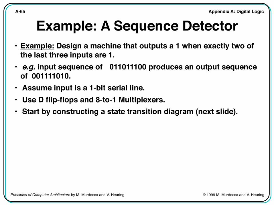
Example: A Sequence Detector• Example: Design a machine that outputs a 1 when exactly two of
the last three inputs are 1.• e.g. input sequence of 011011100 produces an output sequence
of 001111010.• Assume input is a 1-bit serial line.• Use D flip-flops and 8-to-1 Multiplexers.• Start by constructing a state transition diagram (next slide).

Appendix A: Digital LogicA-66
Principles of Computer Architecture by M. Murdocca and V. Heuring © 1999 M. Murdocca and V. Heuring
Sequence Detector State TransitionDiagram
• Design a machine thatoutputs a 1 when ex-actly two of the lastthree inputs are 1.
A
B0/0
1/0C
D
E
F
G
0/0
1/0
0/0
1/0
0/0
1/0
1/0
1/1
0/01/1
0/0
0/1

Appendix A: Digital LogicA-67
Principles of Computer Architecture by M. Murdocca and V. Heuring © 1999 M. Murdocca and V. Heuring
Sequence Detector State Table
X0 1
A B/0 C/0
Present state
Input
BCDE
D/0 E/0F/0 G/0D/0 E/0F/0 G/1
F D/0 E/1G F/1 G/0

Appendix A: Digital LogicA-68
Principles of Computer Architecture by M. Murdocca and V. Heuring © 1999 M. Murdocca and V. Heuring
Sequence Detector State Assignment
X0 1
A: 000 001/0 010/0
Present state
Input
B: 001C: 010D: 011E: 100
011/0 100/0101/0 110/0011/0 100/0101/0 110/1
F: 101 011/0 100/1
S2S1S0 S2S1S0Z S2S1S0Z
G: 110 101/1 110/0
(a)
0011001100110011
0101010101010101
s0 x
0000111100001111
s1
00011101110111dd
0000000011111111
s2
(b)
01100110011001dd
10101010101010dd
00000000010110dd
zs0s1s2
Input and state at time t
Next state and output at
time t+1


FINITE STATE MACHINE SIMPLIFICATION

CIRCUIT MINIMIZATION

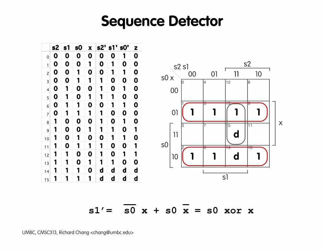
Sequence Detectors2 s1 s0 x s2' s1' s0' z
0 0 0 0 0 0 0 1 01 0 0 0 1 0 1 0 02 0 0 1 0 0 1 1 03 0 0 1 1 1 0 0 04 0 1 0 0 1 0 1 05 0 1 0 1 1 1 0 06 0 1 1 0 0 1 1 07 0 1 1 1 1 0 0 08 1 0 0 0 1 0 1 09 1 0 0 1 1 1 0 1
10 1 0 1 0 0 1 1 011 1 0 1 1 1 0 0 112 1 1 0 0 1 0 1 113 1 1 0 1 1 1 0 014 1 1 1 0 d d d d15 1 1 1 1 d d d d
0d00
1d11
11
11
10
10
00 01 11 10
00
01
11
10
s2 s111
s2
s1
0 4 12 8
1 5 13 9
3 7 15 11
2 6 14 10
s0 x
s0
x
__ s2’= ( s0 + x )(s2 + s1 + s0)
UMBC, CMSC313, Richard Chang <[email protected]>
Sequence Detectors2 s1 s0 x s2' s1' s0' z
0 0 0 0 0 0 0 1 01 0 0 0 1 0 1 0 02 0 0 1 0 0 1 1 03 0 0 1 1 1 0 0 04 0 1 0 0 1 0 1 05 0 1 0 1 1 1 0 06 0 1 1 0 0 1 1 07 0 1 1 1 1 0 0 08 1 0 0 0 1 0 1 09 1 0 0 1 1 1 0 1
10 1 0 1 0 0 1 1 011 1 0 1 1 1 0 0 112 1 1 0 0 1 0 1 113 1 1 0 1 1 1 0 014 1 1 1 0 d d d d15 1 1 1 1 d d d d
1
d
d11
1111
00 01 11 10
00
01
11
10
s2 s111
s2
s1
0 4 12 8
1 5 13 9
3 7 15 11
2 6 14 10
s0 x
s0
x
__ _s1’= s0 x + s0 x = s0 xor x
UMBC, CMSC313, Richard Chang <[email protected]>

Sequence Detectors2 s1 s0 x s2' s1' s0' z
0 0 0 0 0 0 0 1 01 0 0 0 1 0 1 0 02 0 0 1 0 0 1 1 03 0 0 1 1 1 0 0 04 0 1 0 0 1 0 1 05 0 1 0 1 1 1 0 06 0 1 1 0 0 1 1 07 0 1 1 1 1 0 0 08 1 0 0 0 1 0 1 09 1 0 0 1 1 1 0 1
10 1 0 1 0 0 1 1 011 1 0 1 1 1 0 0 112 1 1 0 0 1 0 1 113 1 1 0 1 1 1 0 014 1 1 1 0 d d d d15 1 1 1 1 d d d d
1111
1
d
d11
00 01 11 10
00
01
11
10
s2 s111
s2
s1
0 4 12 8
1 5 13 9
3 7 15 11
2 6 14 10
s0 x
s0
x
_ s0’ = x
UMBC, CMSC313, Richard Chang <[email protected]>

Sequence Detectors2 s1 s0 x s2' s1' s0' z
0 0 0 0 0 0 0 1 01 0 0 0 1 0 1 0 02 0 0 1 0 0 1 1 03 0 0 1 1 1 0 0 04 0 1 0 0 1 0 1 05 0 1 0 1 1 1 0 06 0 1 1 0 0 1 1 07 0 1 1 1 1 0 0 08 1 0 0 0 1 0 1 09 1 0 0 1 1 1 0 1
10 1 0 1 0 0 1 1 011 1 0 1 1 1 0 0 112 1 1 0 0 1 0 1 113 1 1 0 1 1 1 0 014 1 1 1 0 d d d d15 1 1 1 1 d d d d
1
1
1
d
d
00 01 11 10
00
01
11
10
s2 s111
s2
s1
0 4 12 8
1 5 13 9
3 7 15 11
2 6 14 10
s0 x
s0
x
__ _z = s2 s1 x + s2 s1 x
UMBC, CMSC313, Richard Chang <[email protected]>


Notes on K-maps
• Also works for POS
• Takes 2n time for formulas with n variables
• Only optimizes two-level logicReduces number of terms, then number of literals in each term
• Assumes inverters are free
• Does not consider minimizations across functions• Circuit minimization is generally a hard problem
• Quine-McCluskey can be used with more variables
• CAD tools are available if you are serious
UMBC, CMSC313, Richard Chang <[email protected]>

Karnaugh Maps
Implicant: rectangle with 1, 2, 4, 8, 16 ... 1’s
Prime Implicant: an implicant that cannot be extended into a larger implicant
Essential Prime Implicant: the only prime implicant that covers some 1
K-map Algorithm (not from M&H):
1. Find ALL the prime implicants. Be sure to check every 1 and to use don’t cares.
2. Include all essential prime implicants.
3. Try all possibilities to find the minimum cover for the remaining 1’s.
UMBC, CMSC313, Richard Chang <[email protected]>

Circuit Minimization is Hard
• Unix systems store passwords in encrypted form.User types in x, system computes f(x) and looks for f(x) in a file.
• Suppose we us 64-bit passwords and I want to find the password x, such that f(x) = y. Let gi(x) = 0 if f(x) = y and the ith bit of x is 0 1 otherwise.
• If the ith bit of x is 1, then gi(x) outputs 1 for every x and has a very, very simple circuit.
• If you can simplify every circuit quickly, then you can crack passwords quickly.
UMBC, CMSC313, Richard Chang <[email protected]>

Simplifying Finite State Machines
• State Reduction: equivalent FSM with fewer states
• State Assignment: choose an assignment of bit patterns to states (e.g., A is 010) that results in a smaller circuit
• Choice of flip-flops: use D flip-flops, J-K flip-flops or a T flip-flops? a good choice could lead to simpler circuits.
UMBC, CMSC313, Richard Chang <[email protected]>

STATE REDUCTION

Appendix B: Reduction of Digital LogicB-29
Principles of Computer Architecture by M. Murdocca and V. Heuring © 1999 M. Murdocca and V. Heuring
State Reduction• Description of state machine M0 to be reduced.
X0 1
A C/0 E/1
Present state
Input
BCDE
D/0 E/1C/1 B/0C/1 A/0A/0 C/1

UMBC, CMSC 313, Richard Chang <[email protected]>
A
B
C
E
0/1
0/0
0/0
0/0
1/0
1/0
1/1
1/1
State Reduction Example: original transition diagram
D
1/1
0/1

State Reduction Algorithm1. Use a 2-dimensional table — an entry for each pair of states.2. Two states are "distinguished" if:
a. States X and Y of a finite state machine M are distinguished if there exists an input r such that the output of M in state X reading input r is different from the output of M in state Y reading input r.b. States X and Y of a finite state machine are distinguished if there exists an input r such that M in state X reading input r goes to state X', M in state Y reading input r goes to state Y' and we already know that X' and Y' are distinguished states.
3. For each pair (X,Y), check if X and Y are distinguished using the definition above.
4. At the end of the algorithm, states that are not found to be distinguished are in fact equivalent.
UMBC, CMSC313, Richard Chang <[email protected]>

State Reduction Table
• An x entry indicates that the pair of states are known to be distinguished.
• A & B are equivalent, C & D are equivalent
x
x
xxx
xxx
E
D
C
B
A
EDCBA
UMBC, CMSC313, Richard Chang <[email protected]>

UMBC, CMSC 313, Richard Chang <[email protected]>
AB
CD
E
0/1
0/0
0/0
1/1
1/1
State Reduction Example: reduced transition diagram
1/0

State Reduction Algorithm Performance
• As stated, the algorithm takes O(n4) time for a FSM with n states, because each pass takes O(n2) time and we make at most O(n2) passes.
• A more clever implementation takes O(n2) time.• The algorithm produces a FSM with the fewest
number states possible.
• Performance and correctness can be proven.
UMBC, CMSC313, Richard Chang <[email protected]>

STATE ASSIGNMENT

Appendix B: Reduction of Digital LogicB-32
Principles of Computer Architecture by M. Murdocca and V. Heuring © 1999 M. Murdocca and V. Heuring
The State Assignment Problem• Two state assignments for machine M2.
P.S.
Input X0 1
A B/1 A/1B C/0 D/1C C/0 D/0D B/1 A/0
Machine M2
Input X0 1
A: 00 01/1 00/1B: 01 10/0 11/1C: 10 10/0 11/0D: 11 01/1 00/0
State assignment SA0
S0S1
Input X0 1
A: 00 01/1 00/1B: 01 11/0 10/1C: 11 11/0 10/0D: 10 01/1 00/0
State assignment SA1
S0S1

Appendix B: Reduction of Digital LogicB-33
Principles of Computer Architecture by M. Murdocca and V. Heuring © 1999 M. Murdocca and V. Heuring
State Assignment SA0• Boolean equations for machine M2 using state assignment SA0.
01
11
1
10
X0
00S0S1
1 1
11
01
11
1
10
000 1
1
1
1
XS0S1
01
11
1
10
000 1 1
1
1
XS0S1
S0 = S0S1 + S0S1 Z = S0S1 + S0X+ S0S1X
S1 = S0S1X + S0S1X+ S0S1X + S0S1X

Appendix B: Reduction of Digital LogicB-34
Principles of Computer Architecture by M. Murdocca and V. Heuring © 1999 M. Murdocca and V. Heuring
State Assignment SA1• Boolean equations for machine M2 using state assignment SA1.
01
11
1
10
X0
00S0S1
1 1
11
01
11
1
10
000 1
1
1
1
XS0S1
01
11
1
10
00
X
1 1
1
1
S0S10
S1 = XS0 = S1 Z = S1X + S0X

State Assignment Heuristics
• No known efficient alg. for best state assignment
• Some heuristics (rules of thumb):The initial state should be simple to reset — all zeroes or all ones.
Minimize the number of state variables that change on each transition.
Maximize the number of state variables that don't change on each transition.
Exploit symmetries in the state diagram.
If there are unused states (when the number of states s is not a power of 2), choose the unused state variable combinations carefully. (Don't just use the first s combination of state variables.)
Decompose the set of state variables into bits or fields that have well-defined meaning with respect to the input or output behavior.
Consider using more than the minimum number of states to achieve the objectives above.
UMBC, CMSC313, Richard Chang <[email protected]>

APPLY
STATE REDUCTION
& STATE ASSIGNMENT
TO SEQUENCE DETECTOR

Appendix B: Reduction of Digital LogicB-35
Principles of Computer Architecture by M. Murdocca and V. Heuring © 1999 M. Murdocca and V. Heuring
Sequence Detector State TransitionDiagram
A
B0/0
1/0C
D
E
F
G
0/0
1/0
0/0
1/0
0/0
1/0
1/0
1/1
0/01/1
0/0
0/1
Input: 0 1 1 0 1 1 1 0 0Output: 0 0 1 1 1 1 0 1 0Time: 0 1 2 3 4 5 6 7 8

Appendix B: Reduction of Digital LogicB-36
Principles of Computer Architecture by M. Murdocca and V. Heuring © 1999 M. Murdocca and V. Heuring
Sequence Detector State Table
X0 1
A B/0 C/0
Present state
Input
BCDE
D/0 E/0F/0 G/0D/0 E/0F/0 G/1
F D/0 E/1G F/1 G/0

Sequence Detector State Reduction Table
x
xx
xx
xxx
xx
xxx
F
E
FE
x
x
xx
xxx
G
D
C
B
A
GDCBA
UMBC, CMSC313, Richard Chang <[email protected]>

Appendix B: Reduction of Digital LogicB-37
Principles of Computer Architecture by M. Murdocca and V. Heuring © 1999 M. Murdocca and V. Heuring
Sequence Detector Reduced StateTable
X0 1
B'/0 C'/0
Present state
Input
B'/0 D'/0E'/0 F'/0E'/0 F'/1B'/0 D'/1E'/1 F'/0
A: A'BD: B'
C: C'E: D'F: E'G: F'

UMBC, CMSC 313, Richard Chang <[email protected]>
A
B/D
C
E
F
G
0/10/0
0/00/0
0/0
0/0
1/0
1/0
1/0
1/1
1/1
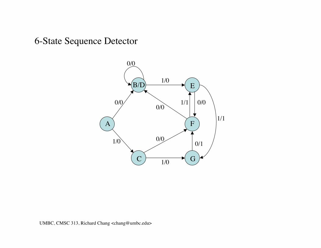
6-State Sequence Detector

Appendix B: Reduction of Digital LogicB-38
Principles of Computer Architecture by M. Murdocca and V. Heuring © 1999 M. Murdocca and V. Heuring
Sequence Detector State Assignment
X0 1
A': 000 001/0 010/0
Present state
Input
B': 001C': 010D': 011E': 100
001/0 011/0100/0 101/0100/0 101/1001/0 011/1
F': 101 100/1 101/0
S2S1S0 S2S1S0Z S2S1S0Z

Appendix B: Reduction of Digital LogicB-40
Principles of Computer Architecture by M. Murdocca and V. Heuring © 1999 M. Murdocca and V. Heuring
Sequence Detector K-Maps
• K-map re-duction ofnext stateand outputfunctions forsequencedetector.
01
11
10
00S0X
1
1
1
1
01 11 10
d
d
d
d
1
1
1
1
00S2S1
01
11
10
00S0X
1
1
01 11 10
d
d
d
d
1
00S2S1
01
11
10
00S0X
1
1 1
10
d
d
d
d
00S2S1
01
11
10
00S0X
1
01 11 10
d
d
d
d
1
1
00S2S1
01 11
S0 = S2S1X + S0X+ S2S0 + S1X
S1 = S2S1X + S2S0X
Z = S2S0X + S1S0X + S2S0X
11
1
S2 = S2S0 + S1

Improved Sequence Detector?
• Formulas from the 7-state FSM: __ s2’= (s0 + x)(s2 + s1 + s0) __ _s1’= s0 x + s0 x = s0 xor x _ s0’= x __ _ z = s2 s1 x + s2 s1 x
• Formulas from the 6-state FSM: s2’= s2 s0 + s1 __ __ __ s1’= s2 s1 x + s2 s0 x __ __ _ __s0’= s2 s1 x + s0 x + s2 s0 + s1 x __ _ z = s2 s0 x + s1 s0 x + s2 s0 x
UMBC, CMSC313, Richard Chang <[email protected]>
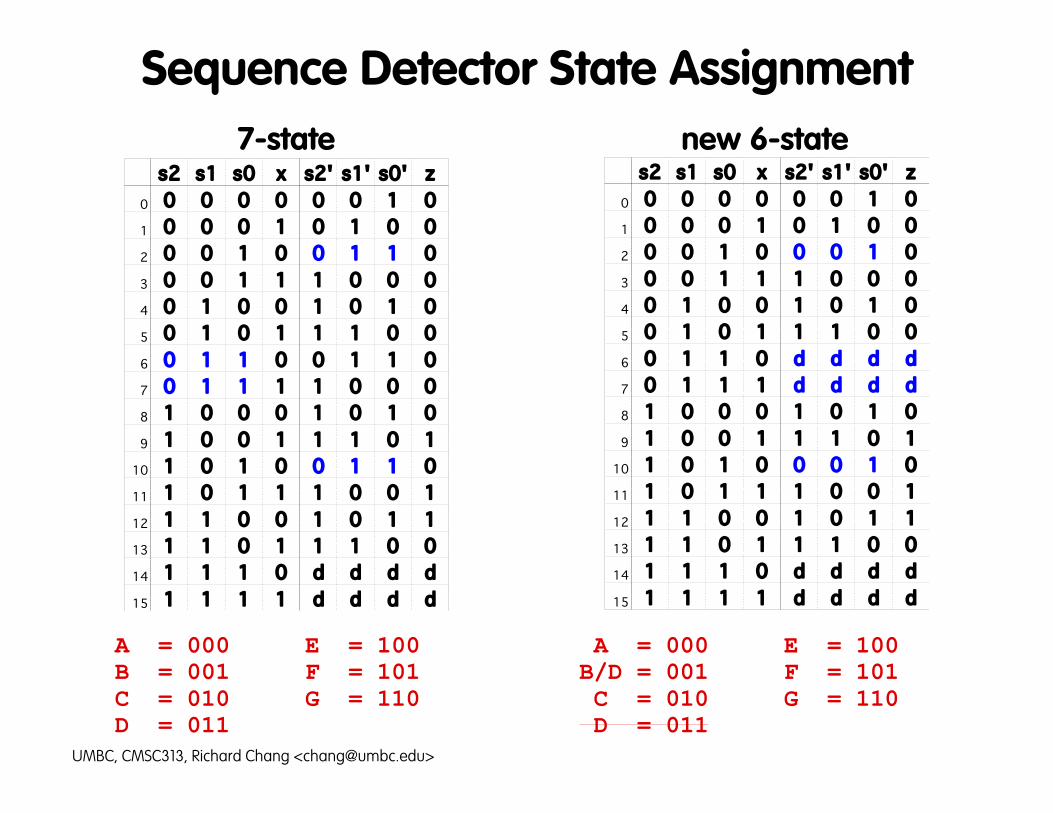
Sequence Detector State Assignment7-state new 6-state
s2 s1 s0 x s2' s1' s0' z0 0 0 0 0 0 0 1 01 0 0 0 1 0 1 0 02 0 0 1 0 0 1 1 03 0 0 1 1 1 0 0 04 0 1 0 0 1 0 1 05 0 1 0 1 1 1 0 06 0 1 1 0 0 1 1 07 0 1 1 1 1 0 0 08 1 0 0 0 1 0 1 09 1 0 0 1 1 1 0 1
10 1 0 1 0 0 1 1 011 1 0 1 1 1 0 0 112 1 1 0 0 1 0 1 113 1 1 0 1 1 1 0 014 1 1 1 0 d d d d15 1 1 1 1 d d d d
s2 s1 s0 x s2' s1' s0' z0 0 0 0 0 0 0 1 01 0 0 0 1 0 1 0 02 0 0 1 0 0 0 1 03 0 0 1 1 1 0 0 04 0 1 0 0 1 0 1 05 0 1 0 1 1 1 0 06 0 1 1 0 d d d d7 0 1 1 1 d d d d8 1 0 0 0 1 0 1 09 1 0 0 1 1 1 0 1
10 1 0 1 0 0 0 1 011 1 0 1 1 1 0 0 112 1 1 0 0 1 0 1 113 1 1 0 1 1 1 0 014 1 1 1 0 d d d d15 1 1 1 1 d d d d
A = 000 E = 100 B = 001 F = 101 C = 010 G = 110 D = 011
A = 000 E = 100B/D = 001 F = 101 C = 010 G = 110 D = 011
UMBC, CMSC313, Richard Chang <[email protected]>
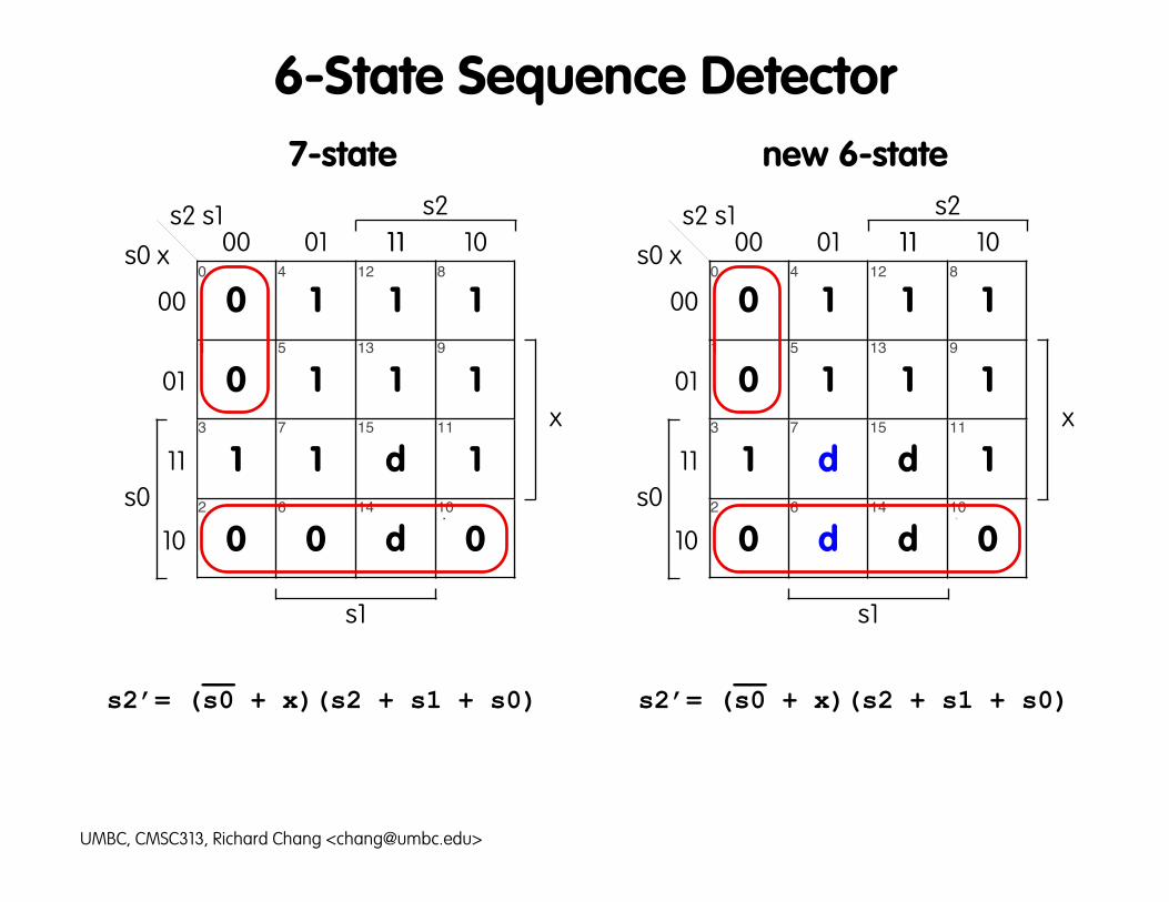
6-State Sequence Detector7-state new 6-state
0d00
1d11
11
11
10
10
00 01 11 10
00
01
11
10
s2 s111
s2
s1
0 4 12 8
1 5 13 9
3 7 15 11
2 6 14 10
s0 x
s0
x
0dd0
1dd1
11
11
10
10
00 01 11 10
00
01
11
10
s2 s111
s2
s1
0 4 12 8
1 5 13 9
3 7 15 11
2 6 14 10
s0 x
s0
x
__ __s2’= (s0 + x)(s2 + s1 + s0) s2’= (s0 + x)(s2 + s1 + s0)
UMBC, CMSC313, Richard Chang <[email protected]>

6-State Sequence Detector7-state new 6-state
1
d
d11
1111
00 01 11 10
00
01
11
10
s2 s111
s2
s1
0 4 12 8
1 5 13 9
3 7 15 11
2 6 14 10
s0 x
s0
x
d
0
d
dd0
1111
00 01 11 10
00
01
11
10
s2 s111
s2
s1
0 4 12 8
1 5 13 9
3 7 15 11
2 6 14 10
s0 x
s0
x
__ _ __s1’= s0 x + s0 x s1’= s0 x
UMBC, CMSC313, Richard Chang <[email protected]>

6-State Sequence Detector7-state new 6-state
1111
1
d
d11
00 01 11 10
00
01
11
10
s2 s111
s2
s1
0 4 12 8
1 5 13 9
3 7 15 11
2 6 14 10
s0 x
s0
x
d
1111
1
d
dd1
00 01 11 10
00
01
11
10
s2 s111
s2
s1
0 4 12 8
1 5 13 9
3 7 15 11
2 6 14 10
s0 x
s0
x
_ _s0’ = x s0’ = x
UMBC, CMSC313, Richard Chang <[email protected]>

6-State Sequence Detector7-state new 6-state
1
1
1
d
d
00 01 11 10
00
01
11
10
s2 s111
s2
s1
0 4 12 8
1 5 13 9
3 7 15 11
2 6 14 10
s0 x
s0
x
d
d 1
1
1
d
d
00 01 11 10
00
01
11
10
s2 s111
s2
s1
0 4 12 8
1 5 13 9
3 7 15 11
2 6 14 10
s0 x
s0
x
__ _ __ _z = s2 s1 x + s2 s1 x z = s2 s1 x + s2 s1 x
UMBC, CMSC313, Richard Chang <[email protected]>

Improved Sequence Detector
• Textbook formulas for the 6-state FSM: s2’= s2 s0 + s1 __ __ __ s1’= s2 s1 x + s2 s0 x __ __ _ __s0’= s2 s1 x + s0 x + s2 s0 + s1 x __ _ z = s2 s0 x + s1 s0 x + s2 s0 x
• New formulas for the 6-state FSM: __ s2’= (s0 + x)(s2 + s1 + s0) __s1’= s0 x _ s0’= x __ _ z = s2 s1 x + s2 s1 x
UMBC, CMSC313, Richard Chang <[email protected]>

CHOICE OF FLIP FLOP

Appendix B: Reduction of Digital LogicB-43
Principles of Computer Architecture by M. Murdocca and V. Heuring © 1999 M. Murdocca and V. Heuring
Excitation Tables• Each table
shows the set-tings that mustbe applied at theinputs at time tin order tochange the out-puts at time t+1.
0011
0101
Qt Qt+1 S
0100
R
0010
S-Rflip-flop
0011
0101
Qt Qt+1 D
0101
Dflip-flop
0011
0101
Qt Qt+1 J
01dd
K
dd10
J-Kflip-flop
0011
0101
Qt Qt+1 T
0110
Tflip-flop

Appendix B: Reduction of Digital LogicB-44
Principles of Computer Architecture by M. Murdocca and V. Heuring © 1999 M. Murdocca and V. Heuring
Serial Adder
SerialAdder
0 1 1 0 00 1 1 1 0
1 1 0 1 0XY
Z
Cin Cout
4 3 2 1 04 3 2 1 0 Time (t)Time (t)
A B00/0
01/1
10/1
11/0
00/1
10/0
01/0
11/1
No carrystate
Carry state
xi yi
zi
Presentstate (St)
Input XY00 01 10 11
A:0 0/0 0/1 0/1 1/0B:1 0/1 1/0 1/0 1/1
Present state
Input XY00 01 10 11
A A/0 A/1 A/1 B/0B A/1 B/0 B/0 B/1
Next state Output
• State transi-tion diagram,state table,and state as-signment fora serial adder.

Appendix B: Reduction of Digital LogicB-45
Principles of Computer Architecture by M. Murdocca and V. Heuring © 1999 M. Murdocca and V. Heuring
Serial Adder Next-State Functions• Truth table showing next-state functions for a serial adder for D,
S-R, T, and J-K flip-flops. Shaded functions are used in the ex-ample.
00110011
01010101
Y St
00001111
X
00010111
D
00000010
S
01000000
R
0d0d0d1d
J
d1d0d0d0
K
01000010
T
01101001
Z
Present State (Set) (Reset)

Appendix B: Reduction of Digital LogicB-46
Principles of Computer Architecture by M. Murdocca and V. Heuring © 1999 M. Murdocca and V. Heuring
J-K Flip-Flop Serial Adder Circuit
CLKQJ
X
Y
Q
XY
Y
X
Z
SKX
Y

Appendix B: Reduction of Digital LogicB-47
Principles of Computer Architecture by M. Murdocca and V. Heuring © 1999 M. Murdocca and V. Heuring
D Flip-Flop Serial Adder Circuit
CLK
QD
X
Y
Q
XY
Y
X
Z
SX
Y

CONSIDER
FLIP FLOP CHOICE
IN SEQUENCE DETECTOR
UMBC, CMSC 313, Richard Chang <[email protected]>
A
B/D
C
E
F
G
0/10/0
0/00/0
0/0
0/0
1/0
1/0
1/0
1/1
1/1
6-State Sequence Detector

Sequence Detector State Assignment7-state new 6-state
s2 s1 s0 x s2' s1' s0' z0 0 0 0 0 0 0 1 01 0 0 0 1 0 1 0 02 0 0 1 0 0 1 1 03 0 0 1 1 1 0 0 04 0 1 0 0 1 0 1 05 0 1 0 1 1 1 0 06 0 1 1 0 0 1 1 07 0 1 1 1 1 0 0 08 1 0 0 0 1 0 1 09 1 0 0 1 1 1 0 1
10 1 0 1 0 0 1 1 011 1 0 1 1 1 0 0 112 1 1 0 0 1 0 1 113 1 1 0 1 1 1 0 014 1 1 1 0 d d d d15 1 1 1 1 d d d d
s2 s1 s0 x s2' s1' s0' z0 0 0 0 0 0 0 1 01 0 0 0 1 0 1 0 02 0 0 1 0 0 0 1 03 0 0 1 1 1 0 0 04 0 1 0 0 1 0 1 05 0 1 0 1 1 1 0 06 0 1 1 0 d d d d7 0 1 1 1 d d d d8 1 0 0 0 1 0 1 09 1 0 0 1 1 1 0 1
10 1 0 1 0 0 0 1 011 1 0 1 1 1 0 0 112 1 1 0 0 1 0 1 113 1 1 0 1 1 1 0 014 1 1 1 0 d d d d15 1 1 1 1 d d d d
A = 000 E = 100 B = 001 F = 101 C = 010 G = 110 D = 011
A = 000 E = 100B/D = 001 F = 101 C = 010 G = 110 D = 011
UMBC, CMSC313, Richard Chang <[email protected]>

6-State Sequence Detector
Q Q' J K
0 0 0 d
0 1 1 d
1 0 d 1
1 1 d 0
s2 s1 s0 x s2' s1' s0' z j2 k2 j1 k1 j0 k0
0 0 0 0 0 0 0 1 0 0 d 0 d 1 d
1 0 0 0 1 0 1 0 0 0 d 1 d 0 d
2 0 0 1 0 0 0 1 0 0 d 0 d d 0
3 0 0 1 1 1 0 0 0 1 d 0 d d 1
4 0 1 0 0 1 0 1 0 1 d d 1 1 d
5 0 1 0 1 1 1 0 0 1 d d 0 0 d
6 0 1 1 0 d d d d d d d d d d
7 0 1 1 1 d d d d d d d d d d
8 1 0 0 0 1 0 1 0 d 0 0 d 1 d
9 1 0 0 1 1 1 0 1 d 0 1 d 0 d
10 1 0 1 0 0 0 1 0 d 1 0 d d 0
11 1 0 1 1 1 0 0 1 d 0 0 d d 1
12 1 1 0 0 1 0 1 1 d 0 d 1 1 d
13 1 1 0 1 1 1 0 0 d 0 d 0 0 d
14 1 1 1 0 d d d d d d d d d d
15 1 1 1 1 d d d d d d d d d d
UMBC, CMSC313, Richard Chang <[email protected]>

6-State Sequence DetectorJ2 K2
ddd0
ddd1
dd
dd
10
10
00 01 11 10
00
01
11
10
s2 s111
s2
s1
0 4 12 8
1 5 13 9
3 7 15 11
2 6 14 10
s0 x
s0
x
1ddd
0ddd
00
00
dd
dd
00 01 11 10
00
01
11
10
s2 s111
s2
s1
0 4 12 8
1 5 13 9
3 7 15 11
2 6 14 10
s0 x
s0
x
_J2 = s1 + s0 x K2 = s0 x
UMBC, CMSC313, Richard Chang <[email protected]>

6-State Sequence DetectorJ1 K1
0dd0
0dd0
1d
0d
d1
d0
00 01 11 10
00
01
11
10
s2 s111
s2
s1
0 4 12 8
1 5 13 9
3 7 15 11
2 6 14 10
s0 x
s0
x
dddd
dddd
d0
d1
0d
1d
00 01 11 10
00
01
11
10
s2 s111
s2
s1
0 4 12 8
1 5 13 9
3 7 15 11
2 6 14 10
s0 x
s0
x
__ _J1 = s0 x K1 = x
UMBC, CMSC313, Richard Chang <[email protected]>

6-State Sequence DetectorJ0 K0
dddd
dddd
00
11
00
11
00 01 11 10
00
01
11
10
s2 s111
s2
s1
0 4 12 8
1 5 13 9
3 7 15 11
2 6 14 10
s0 x
s0
x
0dd0
1dd1
dd
dd
dd
dd
00 01 11 10
00
01
11
10
s2 s111
s2
s1
0 4 12 8
1 5 13 9
3 7 15 11
2 6 14 10
s0 x
s0
x
_J0 = x K0 = x
UMBC, CMSC313, Richard Chang <[email protected]>

Improved Sequence Detector
• Formulas for the 6-state FSM with D Flip-flops: __ s2’= (s0 + x)(s2 + s1 + s0) __s1’= s0 x _ s0’= x
• Formulas for the 6-state FSM with J-K Flip-flops: _J2 = s1 + s0 x K2 = s0 x __ _J1 = s0 x K1 = x _J0 = x K0 = x
UMBC, CMSC313, Richard Chang <[email protected]>
