cmmt-as-c2/3/5/7/12-11a-p3- servo drive
TRANSCRIPT

CMMT-AS-C2/3/5/7/12-11A-P3-...Servo drive
Manual | Assembly,Installation
81537862021-04d[8153788]

Translation of the original instructions
CiA®, EnDat®, EtherCAT®, EtherNet/IP®, DR. JOHANNES HEIDENHAIN®, Hiperface®, PI PROFIBUS PRO-FINET®, PHOENIX CONTACT®, TORX® are registered trademarks of the respective trademark owners incertain countries.
Festo — CMMT-AS-C2/3/5/7/12-11A-P3-... — 2021-04d 3
Table of contents
1 About this document. . . . . . . . . . . . . . . . . . . . . . . . . . . . . . . . . . . . . . . . . . . . . . . . . . . . . . . . . . . . . 51.1 Target group. . . . . . . . . . . . . . . . . . . . . . . . . . . . . . . . . . . . . . . . . . . . . . . . . . . . . . . . . . . . . . . 51.2 Applicable documents. . . . . . . . . . . . . . . . . . . . . . . . . . . . . . . . . . . . . . . . . . . . . . . . . . . . . . . 51.3 Product variants. . . . . . . . . . . . . . . . . . . . . . . . . . . . . . . . . . . . . . . . . . . . . . . . . . . . . . . . . . . . 51.4 Product labelling. . . . . . . . . . . . . . . . . . . . . . . . . . . . . . . . . . . . . . . . . . . . . . . . . . . . . . . . . . . 61.5 Specified standards. . . . . . . . . . . . . . . . . . . . . . . . . . . . . . . . . . . . . . . . . . . . . . . . . . . . . . . . . 9
2 Safety. . . . . . . . . . . . . . . . . . . . . . . . . . . . . . . . . . . . . . . . . . . . . . . . . . . . . . . . . . . . . . . . . . . . . . . . . . 92.1 Safety instructions. . . . . . . . . . . . . . . . . . . . . . . . . . . . . . . . . . . . . . . . . . . . . . . . . . . . . . . . . . 92.2 Intended use. . . . . . . . . . . . . . . . . . . . . . . . . . . . . . . . . . . . . . . . . . . . . . . . . . . . . . . . . . . . . 10
2.2.1 Application areas. . . . . . . . . . . . . . . . . . . . . . . . . . . . . . . . . . . . . . . . . . . . . . . . . 102.2.2 Permissible components. . . . . . . . . . . . . . . . . . . . . . . . . . . . . . . . . . . . . . . . . . . 10
2.3 Training of qualified personnel . . . . . . . . . . . . . . . . . . . . . . . . . . . . . . . . . . . . . . . . . . . . . . . 112.4 CE marking. . . . . . . . . . . . . . . . . . . . . . . . . . . . . . . . . . . . . . . . . . . . . . . . . . . . . . . . . . . . . . . 112.5 Safety engineering approval . . . . . . . . . . . . . . . . . . . . . . . . . . . . . . . . . . . . . . . . . . . . . . . . . 112.6 UL/CSA certification. . . . . . . . . . . . . . . . . . . . . . . . . . . . . . . . . . . . . . . . . . . . . . . . . . . . . . . 11
3 Additional information. . . . . . . . . . . . . . . . . . . . . . . . . . . . . . . . . . . . . . . . . . . . . . . . . . . . . . . . . . 114 Product overview. . . . . . . . . . . . . . . . . . . . . . . . . . . . . . . . . . . . . . . . . . . . . . . . . . . . . . . . . . . . . . . 11
4.1 Scope of delivery. . . . . . . . . . . . . . . . . . . . . . . . . . . . . . . . . . . . . . . . . . . . . . . . . . . . . . . . . . 114.2 System structure. . . . . . . . . . . . . . . . . . . . . . . . . . . . . . . . . . . . . . . . . . . . . . . . . . . . . . . . . . 12
4.2.1 Product design. . . . . . . . . . . . . . . . . . . . . . . . . . . . . . . . . . . . . . . . . . . . . . . . . . . 144.2.2 Overview of connection technology. . . . . . . . . . . . . . . . . . . . . . . . . . . . . . . . . . 16
5 Transport and storage. . . . . . . . . . . . . . . . . . . . . . . . . . . . . . . . . . . . . . . . . . . . . . . . . . . . . . . . . . . 186 Assembly. . . . . . . . . . . . . . . . . . . . . . . . . . . . . . . . . . . . . . . . . . . . . . . . . . . . . . . . . . . . . . . . . . . . . . 18
6.1 Mounting distances. . . . . . . . . . . . . . . . . . . . . . . . . . . . . . . . . . . . . . . . . . . . . . . . . . . . . . . . 206.2 Installation. . . . . . . . . . . . . . . . . . . . . . . . . . . . . . . . . . . . . . . . . . . . . . . . . . . . . . . . . . . . . . . 22
7 Installation. . . . . . . . . . . . . . . . . . . . . . . . . . . . . . . . . . . . . . . . . . . . . . . . . . . . . . . . . . . . . . . . . . . . 237.1 Safety. . . . . . . . . . . . . . . . . . . . . . . . . . . . . . . . . . . . . . . . . . . . . . . . . . . . . . . . . . . . . . . . . . . 237.2 Residual current protective device. . . . . . . . . . . . . . . . . . . . . . . . . . . . . . . . . . . . . . . . . . . . 247.3 Mains fuse. . . . . . . . . . . . . . . . . . . . . . . . . . . . . . . . . . . . . . . . . . . . . . . . . . . . . . . . . . . . . . . 257.4 Permissible and impermissible mains types of system earthing. . . . . . . . . . . . . . . . . . . 267.5 Connection of the mains side PE conductor. . . . . . . . . . . . . . . . . . . . . . . . . . . . . . . . . . . . 317.6 Information on EMC-compliant installation. . . . . . . . . . . . . . . . . . . . . . . . . . . . . . . . . . . . 317.7 Connection examples. . . . . . . . . . . . . . . . . . . . . . . . . . . . . . . . . . . . . . . . . . . . . . . . . . . . . . 357.8 Interfaces. . . . . . . . . . . . . . . . . . . . . . . . . . . . . . . . . . . . . . . . . . . . . . . . . . . . . . . . . . . . . . . . 36
7.8.1 [X1A], inputs and outputs for the higher-order PLC. . . . . . . . . . . . . . . . . . . . . . 367.8.2 [X1C], inputs and outputs for the axis . . . . . . . . . . . . . . . . . . . . . . . . . . . . . . . . . 427.8.3 [X2], encoder interface 1. . . . . . . . . . . . . . . . . . . . . . . . . . . . . . . . . . . . . . . . . . . 447.8.4 [X3], encoder interface 2. . . . . . . . . . . . . . . . . . . . . . . . . . . . . . . . . . . . . . . . . . . . 507.8.5 [X10], SYNC IN/OUT. . . . . . . . . . . . . . . . . . . . . . . . . . . . . . . . . . . . . . . . . . . . . . . 547.8.6 [X18], Standard Ethernet. . . . . . . . . . . . . . . . . . . . . . . . . . . . . . . . . . . . . . . . . . . 577.8.7 [X19], Real-time Ethernet (RTE) port 1 and port 2. . . . . . . . . . . . . . . . . . . . . . . 59

4 Festo — CMMT-AS-C2/3/5/7/12-11A-P3-... — 2021-04d
7.9 Motor connection. . . . . . . . . . . . . . . . . . . . . . . . . . . . . . . . . . . . . . . . . . . . . . . . . . . . . . . . . 617.9.1 [X6A], motor phase connection. . . . . . . . . . . . . . . . . . . . . . . . . . . . . . . . . . . . . . 617.9.2 [X6B], motor auxiliary connection. . . . . . . . . . . . . . . . . . . . . . . . . . . . . . . . . . . . 637.9.3 Electronic overload and over temperature protection for the motor. . . . . . . . 647.9.4 Shield support of the motor cable. . . . . . . . . . . . . . . . . . . . . . . . . . . . . . . . . . . . 65
7.10 Power and logic voltage supply. . . . . . . . . . . . . . . . . . . . . . . . . . . . . . . . . . . . . . . . . . . . . . 697.10.1 [X9A], power supply and DC link circuit connection. . . . . . . . . . . . . . . . . . . . . . 697.10.2 [X9C], logic voltage supply. . . . . . . . . . . . . . . . . . . . . . . . . . . . . . . . . . . . . . . . . . 707.10.3 [X9B], connection for braking resistor . . . . . . . . . . . . . . . . . . . . . . . . . . . . . . . . . 72
7.11 Cross-wiring. . . . . . . . . . . . . . . . . . . . . . . . . . . . . . . . . . . . . . . . . . . . . . . . . . . . . . . . . . . . . . 747.11.1 Cross-wiring of the I/O signals at the connection [X1A] . . . . . . . . . . . . . . . . . . 747.11.2 Cross-wiring of the mains and logic voltage supply. . . . . . . . . . . . . . . . . . . . . . 77
8 Malfunctions. . . . . . . . . . . . . . . . . . . . . . . . . . . . . . . . . . . . . . . . . . . . . . . . . . . . . . . . . . . . . . . . . . . 838.1 Diagnostics via LED. . . . . . . . . . . . . . . . . . . . . . . . . . . . . . . . . . . . . . . . . . . . . . . . . . . . . . . . 83
8.1.1 Device status displays. . . . . . . . . . . . . . . . . . . . . . . . . . . . . . . . . . . . . . . . . . . . . 848.1.2 Interface status [X2], [X3], [X10], [X18] . . . . . . . . . . . . . . . . . . . . . . . . . . . . . . . . 888.1.3 Device and interface status, EtherCAT. . . . . . . . . . . . . . . . . . . . . . . . . . . . . . . . 888.1.4 Device and interface status, PROFINET. . . . . . . . . . . . . . . . . . . . . . . . . . . . . . . . 908.1.5 Device and interface status, EtherNet/IP. . . . . . . . . . . . . . . . . . . . . . . . . . . . . . 91
9 Disassembly. . . . . . . . . . . . . . . . . . . . . . . . . . . . . . . . . . . . . . . . . . . . . . . . . . . . . . . . . . . . . . . . . . . 9210 Technical data. . . . . . . . . . . . . . . . . . . . . . . . . . . . . . . . . . . . . . . . . . . . . . . . . . . . . . . . . . . . . . . . . . 93
10.1 General technical data. . . . . . . . . . . . . . . . . . . . . . . . . . . . . . . . . . . . . . . . . . . . . . . . . . . . . 9310.2 Technical data, electrical . . . . . . . . . . . . . . . . . . . . . . . . . . . . . . . . . . . . . . . . . . . . . . . . . . . . 96
10.2.1 Load voltage supply [X9A] . . . . . . . . . . . . . . . . . . . . . . . . . . . . . . . . . . . . . . . . . . 9610.2.2 Logic voltage supply [X9C] . . . . . . . . . . . . . . . . . . . . . . . . . . . . . . . . . . . . . . . . . . 9810.2.3 Electrical data for braking resistor (internal/external) [X9B] . . . . . . . . . . . . . . 9910.2.4 Power specifications, motor connection [X6A] . . . . . . . . . . . . . . . . . . . . . . . . . 10110.2.5 Motor auxiliary connection [X6B] . . . . . . . . . . . . . . . . . . . . . . . . . . . . . . . . . . . 10410.2.6 Encoder interfaces [X2], [X3] . . . . . . . . . . . . . . . . . . . . . . . . . . . . . . . . . . . . . . . 10510.2.7 Inputs, outputs, ready contact at [X1A] . . . . . . . . . . . . . . . . . . . . . . . . . . . . . . 11010.2.8 Inputs and outputs for the axis [X1C] . . . . . . . . . . . . . . . . . . . . . . . . . . . . . . . . 11610.2.9 SYNC IN/OUT [X10] . . . . . . . . . . . . . . . . . . . . . . . . . . . . . . . . . . . . . . . . . . . . . . . 11810.2.10 Standard Ethernet [X18], parameterisation interface. . . . . . . . . . . . . . . . . . . 11910.2.11 Real-time Ethernet [X19] ([XF1 IN], [XF2 OUT]) . . . . . . . . . . . . . . . . . . . . . . . . . 119
10.3 Technical data UL/CSA certification. . . . . . . . . . . . . . . . . . . . . . . . . . . . . . . . . . . . . . . . . . 12010.4 Operation of the servo drive in the system. . . . . . . . . . . . . . . . . . . . . . . . . . . . . . . . . . . . 123
10.4.1 Cable lengths in combination with Festo motors. . . . . . . . . . . . . . . . . . . . . . . 12310.4.2 Power loss. . . . . . . . . . . . . . . . . . . . . . . . . . . . . . . . . . . . . . . . . . . . . . . . . . . . . . 126
Festo — CMMT-AS-C2/3/5/7/12-11A-P3-... — 2021-04d
About this document
5
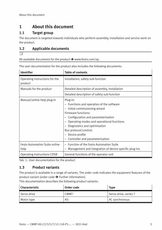
1 About this document1.1 Target groupThe document is targeted towards individuals who perform assembly, installation and service work onthe product.
1.2 Applicable documents
All available documents for the product è www.festo.com/sp.
The user documentation for the product also includes the following documents:
Identifier Table of contents
Operating instructions for theproduct
Installation, safety sub-function
Manuals for the product Detailed description of assembly, installation
Detailed description of safety sub-function
Manual/online help plug-in Plug-in:– Functions and operation of the software– Initial commissioning wizardFirmware functions:– Configuration and parameterisation– Operating modes and operational functions– Diagnostics and optimisationBus protocol/control:– Device profile– Controller and parameterisation
Festo Automation Suite onlinehelp
– Function of the Festo Automation Suite– Management and integration of device-specific plug-ins
Operating instructions CDSB General functions of the operator unit
Tab. 1: User documentation for the product
1.3 Product variantsThe product is available in a range of variants. The order code indicates the equipment features of theproduct variant (order code è Further information).This documentation describes the following product variants:
Characteristic Order code Type
Servo drive CMMT- Servo drive, series T
Motor type AS- AC synchronous

6 Festo — CMMT-AS-C2/3/5/7/12-11A-P3-... — 2021-04d
About this document
Characteristic Order code Type
Nominal current C2- 2 A
C3- 3 A
C5- 5 A
C7- 7 A
C12- 12 A
Nominal input voltage 11A- 400 V AC, 50 … 60 Hz
Number of phases P3- 3-phase
Bus protocol/control EC- EtherCAT
EP- EtherNet/IP
PN- PROFINET
Safety function S1 Standard safety
Cooling method – Integrated cooling element
Firmware type – Basic type
C..- Customer variant …
S..- Sales variant …
Firmware version – Basic version
V..- Version …
Approval – CE-compliant basic version
Tab. 2: Product variants CMMT-AS-...-11A-P3 (e.g. CMMT-AS-C3-11A-P3-EC-S1)
This documentation refers to the following version:– Servo drive CMMT-AS-...-S1, revision R01 and higher, see product labelling.This is the first available revision.• For later revisions of the product, check whether updated documentation is availableè www.festo.com/pk.
1.4 Product labelling• Observe the specifications on the product.The product labelling is located on the right side of the device. The product labelling enables identifi-cation of the product and shows the following information, for example:
Product labelling (example) Meaning
CMMT-AS-C2-11A-P3-EC-S1 Order code
5340821 MM-YYYY : J302 Rev 00 Part number, serial number (MM = productionmonth, YYYY = production year, plant number),revision (Rev)

Festo — CMMT-AS-C2/3/5/7/12-11A-P3-... — 2021-04d
About this document
7
Product labelling (example) Meaning
Main input: 3 x 200 V AC - 10% … 480 V AC + 10%48 … 62 Hz 2 ARMS
Technical data on power supply (alternatingcurrent supply connection)
Motor out: 3 x 0 … Input V AC 0 … 599 Hz1.7 ARMS 0.8 kW
Technical data for the motor output (outputvoltage, max. output frequency, nominal cur-rent, nominal output power)
TAMB: max. 40 °C Ambient temperature (TAMB)
IP10/20 PD2 Degree of protection, without mating plug/withmating plug X9A attached; pollution degree
SCCR: 10 kAcUL restriction: Only for use in WYE 480 V/277 Vsupply sources1)
SCCR (short circuit current rating)Operation on power supply systems with SCCR£ 10 kA è 10.3 Technical data UL/CSA certifi-cationSpecification of the permissible SCCR value.Depending on the product variant, additionalspecifications or restrictions may apply
R-R-FTO-KC-2018-1054 KC mark certificate (test mark for Korea)
MAC: XX-XX-XX-XX-XX-XX first MAC address of the device for Ethernetcommunication
See manual for additional information Reference to the existing user documentation,which contains information on overload protec-tion and the necessary external circuit breaker.
Data matrix code 123456789AB Product key as a data matrix code and an 11-character alphanumeric code
Festo SE & Co. KG Manufacturer
DE-73734 Esslingen Manufacturer’s address
Made in Germany Country of origin Germany
1) only for product versions with corresponding restrictions
Tab. 3: Product labelling (example)
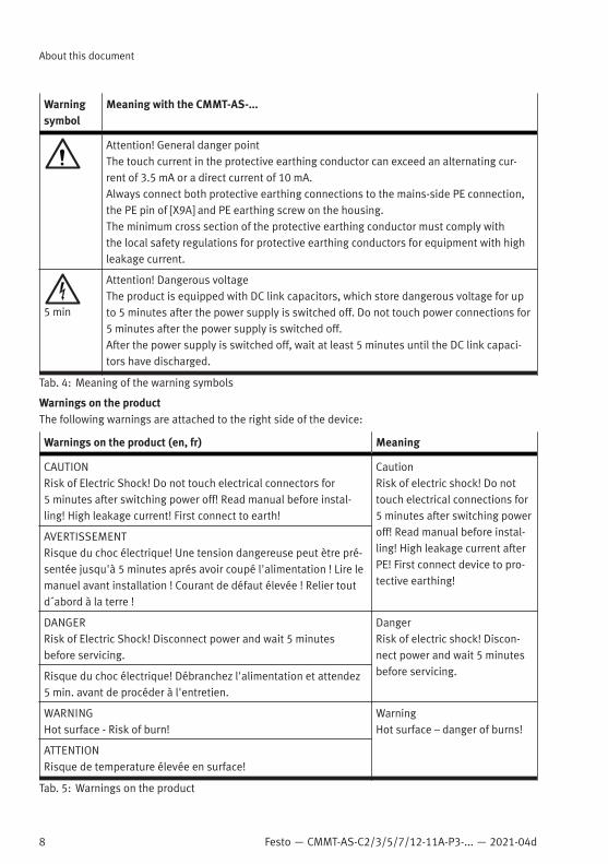
Warning symbols on the front of the product
Warningsymbol
Meaning with the CMMT-AS-...
Attention! Hot surfaceMetallic housing parts of the device can reach high temperatures during operation.In the event of a fault, internal components may become overloaded. Overloading ofcomponents can result in high temperatures and the release of hot gases.
8 Festo — CMMT-AS-C2/3/5/7/12-11A-P3-... — 2021-04d
About this document
Warningsymbol
Meaning with the CMMT-AS-...
Attention! General danger pointThe touch current in the protective earthing conductor can exceed an alternating cur-rent of 3.5 mA or a direct current of 10 mA.Always connect both protective earthing connections to the mains-side PE connection,the PE pin of [X9A] and PE earthing screw on the housing.The minimum cross section of the protective earthing conductor must comply withthe local safety regulations for protective earthing conductors for equipment with highleakage current.
5 min
Attention! Dangerous voltageThe product is equipped with DC link capacitors, which store dangerous voltage for upto 5 minutes after the power supply is switched off. Do not touch power connections for5 minutes after the power supply is switched off.After the power supply is switched off, wait at least 5 minutes until the DC link capaci-tors have discharged.
Tab. 4: Meaning of the warning symbols
Warnings on the productThe following warnings are attached to the right side of the device:
Warnings on the product (en, fr) Meaning
CAUTIONRisk of Electric Shock! Do not touch electrical connectors for5 minutes after switching power off! Read manual before instal-ling! High leakage current! First connect to earth!
CautionRisk of electric shock! Do nottouch electrical connections for5 minutes after switching poweroff! Read manual before instal-ling! High leakage current afterPE! First connect device to pro-tective earthing!
AVERTISSEMENTRisque du choc électrique! Une tension dangereuse peut ètre pré-sentée jusqu'à 5 minutes aprés avoir coupé l'alimentation ! Lire lemanuel avant installation ! Courant de défaut élevée ! Relier toutd´abord à la terre !
DANGERRisk of Electric Shock! Disconnect power and wait 5 minutesbefore servicing.
DangerRisk of electric shock! Discon-nect power and wait 5 minutesbefore servicing.Risque du choc électrique! Débranchez l'alimentation et attendez
5 min. avant de procéder à l'entretien.
WARNINGHot surface - Risk of burn!
WarningHot surface – danger of burns!
ATTENTIONRisque de temperature élevée en surface!
Tab. 5: Warnings on the product
Festo — CMMT-AS-C2/3/5/7/12-11A-P3-... — 2021-04d
Safety
9
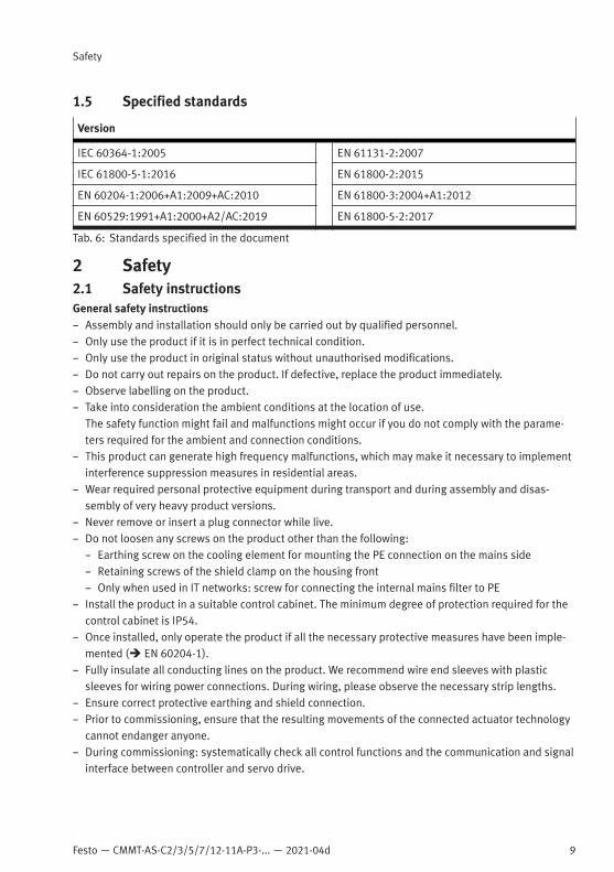
1.5 Specified standards
Version
IEC 60364-1:2005 EN 61131-2:2007
IEC 61800-5-1:2016 EN 61800-2:2015
EN 60204-1:2006+A1:2009+AC:2010 EN 61800-3:2004+A1:2012
EN 60529:1991+A1:2000+A2/AC:2019 EN 61800-5-2:2017
Tab. 6: Standards specified in the document
2 Safety2.1 Safety instructionsGeneral safety instructions– Assembly and installation should only be carried out by qualified personnel.– Only use the product if it is in perfect technical condition.– Only use the product in original status without unauthorised modifications.– Do not carry out repairs on the product. If defective, replace the product immediately.– Observe labelling on the product.– Take into consideration the ambient conditions at the location of use.
The safety function might fail and malfunctions might occur if you do not comply with the parame-ters required for the ambient and connection conditions.
– This product can generate high frequency malfunctions, which may make it necessary to implementinterference suppression measures in residential areas.
– Wear required personal protective equipment during transport and during assembly and disas-sembly of very heavy product versions.
– Never remove or insert a plug connector while live.– Do not loosen any screws on the product other than the following:– Earthing screw on the cooling element for mounting the PE connection on the mains side– Retaining screws of the shield clamp on the housing front– Only when used in IT networks: screw for connecting the internal mains filter to PE
– Install the product in a suitable control cabinet. The minimum degree of protection required for thecontrol cabinet is IP54.
– Once installed, only operate the product if all the necessary protective measures have been imple-mented (è EN 60204-1).
– Fully insulate all conducting lines on the product. We recommend wire end sleeves with plasticsleeves for wiring power connections. During wiring, please observe the necessary strip lengths.
– Ensure correct protective earthing and shield connection.– Prior to commissioning, ensure that the resulting movements of the connected actuator technology
cannot endanger anyone.– During commissioning: systematically check all control functions and the communication and signal
interface between controller and servo drive.

10 Festo — CMMT-AS-C2/3/5/7/12-11A-P3-... — 2021-04d
Safety
– The product is equipped with DC link capacitors, which store dangerous voltage for up to 5 minutesafter the power supply is switched off. Before working on the product, switch off the power supplyvia the main switch and secure it against being switched on again unintentionally. Before touchingthe power connections, wait at least 5 minutes.
– Take into consideration the legal regulations for the installation location.– Keep the documentation somewhere safe throughout the entire product lifecycle.In the event of damage caused by unauthorised manipulation or any use other than the intended use,the guarantee will be invalidated and the manufacturer will not be liable for damages.In the event of damage caused by using unauthorised software or firmware with the device, thewarranty will be invalidated, and the manufacturer will not be liable for damages.
Safety instructions for the safety sub-functions of the product è Manual Safety sub-function.
2.2 Intended useThe servo drive CMMT-AS is intended for supply and control of AC servo motors. The integratedelectronics permit regulation of torque (current), rotational speed and position.Use exclusively:– in perfect technical condition– in original condition without unauthorised modifications; only the extensions described in the
documentation supplied with the product are permitted– within the limits of the product defined by the technical data è Technical data– in an industrial environmentThe safety function might fail and malfunctions might occur if you do not comply with the parametersrequired for the ambient and connection conditions.
Intended use of the safety sub-functions for the product è Manual Safety sub-function.
2.2.1 Application areas
The device is intended for use in an industrial environment and with appropriate measures in commer-cial, residential and mixed areas.The device is intended for installation in a control cabinet. The minimum degree of protection requiredfor the control cabinet is IP54.The device can be operated in TN, TT and IT systems if certain requirements are met. Detailed informa-tion on allowed and prohibited mains types of system earthing è 7.4 Permissible and impermissiblemains types of system earthing.
2.2.2 Permissible components
If holding brakes and clamping units without certification are used, a risk assessment is required toassess their suitability for the related safety-oriented application.
Festo — CMMT-AS-C2/3/5/7/12-11A-P3-... — 2021-04d
Product overview
11
In addition to the requirements of EN 60204-1, the following requirements apply to other componentsof the drive system from EN 61800-5-2:– Annex D.3.5 and D.3.6 for motors– Annex D.3.1 for motor and brake cables– Annex D.3.4 for mating plugsComponents approved by Festo for the CMMT-AS fulfil these requirements.
2.3 Training of qualified personnelThe product may be installed and placed in operation only by a qualified electro technician, who isfamiliar with the topics:– installation and operation of electrical control systems– applicable regulations for operating safety-engineering systemsWork on safety-related systems may only be carried out by qualified personnel trained in safetyengineering.
2.4 CE markingThe product has the CE marking.The product-related EC/EU directives and standards are listed in the declaration of conformityè www.festo.com/sp.
2.5 Safety engineering approvalThe product is a safety device in accordance with the Machinery Directive. For details of the safety-ori-ented standards and test values with which the product complies and fulfils, see è Manual Safetysub-function, Technical data, safety engineering.
2.6 UL/CSA certificationTechnical data and environmental conditions may be subject to change in order to comply withUnderwriters Laboratories Inc. (UL) certification requirements for the USA and Canada.Deviating values è 10.3 Technical data UL/CSA certification.
3 Additional information– Contact the regional Festo contact if you have technical problems è www.festo.com.– Accessories and spare parts è www.festo.com/catalogue.
Firmware, software or configuration files è www.festo.com/sp.
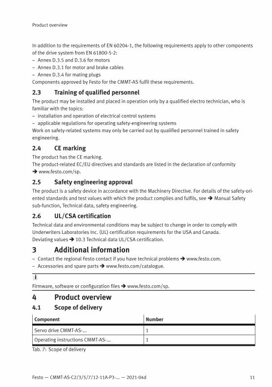
4 Product overview4.1 Scope of delivery
Component Number
Servo drive CMMT-AS-... 1
Operating instructions CMMT-AS-... 1
Tab. 7: Scope of delivery
12 Festo — CMMT-AS-C2/3/5/7/12-11A-P3-... — 2021-04d
Product overview
Below are some examples of the available accessories:– Plug connector set for single wiring connection NEKM-C6-...-S– Plug connector set for double wiring connection NEKM-C6-...-D– External braking resistor CACR-...– Motor cable NEBM-... , e.g. for the motor series EMMS-AS, EMME-AS and EMMT-AS– Encoder cable, e.g. for the motor series EMMS-AS and EMME-AS– Patch cable NEBC-..., e.g. for linkage of the RTE interface [X19A/B]– Display and operating unit CDSB-...– Mains filter CAMF-C6-F– Line choke CAMF-C6-FD
Up-to-date information on the accessories è www.festo.com/catalogue.
4.2 System structureThe servo drive CMMT-AS is a 1-axis servo drive. Depending on the product variant, the followingcomponents, which are necessary for standard applications, are integrated into the device or into thecooling profile of the device:– Mains filter (guarantees immunity to interference and limits conducted emissions)– Electronics for DC link voltage conditioning– Power stage (for motor control)– Braking resistor (integrated into the cooling element)– Brake chopper (switches the braking resistor in the DC link circuit, if and when required)– Temperature sensors (for monitoring the temperature of the power module and of the air in the
device)– Fan in the cooling profile (depending on product variant)The device has separate connections for logic and load voltage supply. The load voltage supply comesdirectly from the low-voltage network. The logic supply must be provided by a PELV fixed power supply(+24 V DC).The servo drive includes the option of connecting 2 encoders. In addition, the device has 1 switchingoutput for direct connection of the holding brake in the motor and 1 output for control of an externalclamping unit.An external braking resistor can be connected instead of the internal braking resistor, if necessary.The servo drive features a real-time Ethernet interface for process control. Various bus protocols aresupported depending on the product design (EtherCAT, EtherNet/IP or PROFINET).The device can be parameterised via a PC using either the real-time Ethernet interface or the separatestandard Ethernet interface.If required, the CDSB operator unit can be plugged in at the top of the front panel of the device. TheCDSB displays, for example, diagnostic information as well as setpoint and actual values in plain text.To enable you to operate several servo drives in a device compound, the DC link circuits of severaldevices can be coupled, and the power supplies and I/O signals of the devices can be linked throughcross-wiring. The DC link coupling can increase the energy efficiency of the device compound.

Festo — CMMT-AS-C2/3/5/7/12-11A-P3-... — 2021-04d
Product overview
13
Festo recommends use of servo motors, electromechanical drives, lines and accessories from theFesto accessory programme.
1
2
3
4
5
6
7
8
Fig. 1: System structure (example)
1 Bus/network
2 Main switch
3 Automatic circuit breaker/fuses and all-current-sensitive RCD (residual currentdevice) (optional)
4 Fixed power supply for logic voltage supply24 V DC (PELV)
5 External braking resistor (optional)
6 Servo drive CMMT-AS
7 Servo motor (here EMME-AS)
8 PC with Ethernet connection for parameter-isation

14 Festo — CMMT-AS-C2/3/5/7/12-11A-P3-... — 2021-04d
Product overview
4.2.1 Product design
The device has a compact design. The connections are on the front and top of the device as pinheader, socket strip or RJ45 bushing. The shield clamp and strain relief for the motor cable are situatedin the lower area of the front panel.
1
2
3
4
5
6
Fig. 2: Servo drive CMMT-AS-C2/C3/C5-11A-P3 (example)
1 Hood
2 Cooling element
3 Top of device
4 Blind plate
5 Front panel
6 Shield clamp and strain relief for motorcable
The cooling element on the back of the device serves to dissipate the heat from internal componentsto the ambient air. The cooling element has one slot each on the top and bottom for mounting thedevice on the rear wall of the control cabinet. If an operator unit is not required, the upper area iscovered with a blind plate.

Festo — CMMT-AS-C2/3/5/7/12-11A-P3-... — 2021-04d
Product overview
15
The back of the device is part of the cooling element. The braking resistor is integrated in the air ductof the cooling element. The connecting cable for the braking resistor is passed from the cooling profile,emerges from the top of the cooling profile and is connected to the connection [X9B].The product variant CMMT-AS-C5-11A-P3 has a fan located in the air duct of the cooling element.Some devices also have a fan in the interior. The device controls the fans independently. The fans areonly switched on briefly when the device is switched on, and as needed. The fans draw in cold ambientair from beneath and blow the air upward through the profile. The air picks up heat from the profile inthe process.
1
2
3
2
5
4
Fig. 3: Back
1 Top slot (keyhole shape)
2 Retaining screw for braking resistor (2x)
3 Braking resistor
4 Bottom slot
5 Fan (CMMT-AS-C5/C7/C12-11A-P3 only)

16 Festo — CMMT-AS-C2/3/5/7/12-11A-P3-... — 2021-04d
Product overview
4.2.2 Overview of connection technology
1
2
3
4
5
6
7
8
9
10
11
12
13
14
15
16
Fig. 4: Connections of the CMMT-AS-C2-11A-P3 (example)
1 PE connection, housing
2 [X9A] Mains and DC link circuit connection
3 [X9C] Logic voltage
4 [XF2 OUT] RTE interface port 2
5 [XF1 IN] RTE interface port 1
6 [X1C] inputs/outputs for the axis
7 [X6B] motor auxiliary connection
8 [X6A] motor phase connection
9 Shield clamp of motor cable
10 [X2] encoder connection 1
11 [X3] encoder connection 2
12 [X10] device synchronisation
13 [X18] standard Ethernet
14 [X5] connection for operator unit (behindthe blind plate)
15 [X1A] I/O interface
16 [X9B] connection for braking resistor

Festo — CMMT-AS-C2/3/5/7/12-11A-P3-... — 2021-04d
Product overview
17
12
3
4
5
6
7
8
9
10
11
12
13
14
15
16
Fig. 5: Connections of the CMMT-AS-C7/C12-11A-P3 (example)
1 PE connection, housing
2 [X9A] Mains and DC link circuit connection
3 [X9C] Logic voltage
4 [XF2 OUT] RTE interface port 2
5 [XF1 IN] RTE interface port 1
6 [X1C] inputs/outputs for the axis
7 [X6B] motor auxiliary connection
8 [X6A] motor phase connection
9 Shield clamp of motor cable
10 [X2] encoder connection 1
11 [X3] encoder connection 2
12 [X10] device synchronisation
13 [X18] standard Ethernet
14 [X5] connection for operator unit (behindthe blind plate)
15 [X1A] I/O interface
16 [X9B] connection for braking resistor

18 Festo — CMMT-AS-C2/3/5/7/12-11A-P3-... — 2021-04d
Assembly
The blind plate can be pulled off by hand without tools. The operator unit CDSB can be plugged intothe free space è Documentation on the CDSB. If an operator unit is not used, the upper area must besealed with the blind plate.
5 Transport and storage– Protect the product during transport and storage from excessive stress factors. Excessive stress
factors include:– mechanical stresses– impermissible temperatures– moisture– aggressive atmospheres
– Store and transport the product in its original packaging. The original packaging offers sufficientprotection from typical stresses.
6 AssemblyDimensions CMMT-AS-C2/C3/C5-11A-P3...
Fig. 6: Dimensions

Festo — CMMT-AS-C2/3/5/7/12-11A-P3-... — 2021-04d
Assembly
19
Dimen-sion
L1 L2 L3 L4 L5 L6 L7
[mm] Approx.242
200 220 22 10 6 16
Tab. 8: Dimensions CMMT-AS-C2/C3/C5-11A-P3... Part 1
Dimen-sion
H1 H2 B1 B2 B3 D1 D2 D3
[mm] Approx.218
Approx.205
Approx.60
42 B1/2 R5.5 5.5 5.5
Tab. 9: Dimensions CMMT-AS-C2/C3/C5-11A-P3... Part 2
Dimensions CMMT-AS-C7 / C12-11A-P3...
Fig. 7: Dimensions

20 Festo — CMMT-AS-C2/3/5/7/12-11A-P3-... — 2021-04d
Assembly
Dimension L1 L2 L3 L4 L5 L6 L7
[mm] Approx.319
276 300 22 10 6 13
Tab. 10: Dimensions CMMT-AS-C7 / C12-11A-P3... Part 1
Dimen-sion
H1 H2 B1 B2 B3 D1 D2 D3
[mm] Approx.224
Approx.205
Approx.75
44 B1/2 R5.5 5.5 5.5
Tab. 11: Dimensions CMMT-AS-C7 / C12-11A-P3... Part 2
6.1 Mounting distancesThe servo drives of the series CMMT-AS can be arrayed next to each other. When arraying devices, therequired minimum distance must be maintained so that the heat generated during operation can bedissipated by allowing sufficient air flow.Mounting distances for CMMT-AS-C2/C3/C5-11A-P3...
Fig. 8: Mounting distances and installation clearance for CMMT-AS-C2/C3/C5-...-11A-P3 (3-phase)

Festo — CMMT-AS-C2/3/5/7/12-11A-P3-... — 2021-04d
Assembly
21
Servo drive H1 H21) L1 L2 L3
CMMT-AS-C2-11A-P3... [mm] 100 70 62 70 220
CMMT-AS-C3-11A-P3... [mm]
CMMT-AS-C5-11A-P3 [mm]
1) An installation clearance of 150 mm is recommended for compliance with clearance H2 and for optimum routing of the motor andencoder cables on the underside of the housing!
Tab. 12: Mounting distances and installation clearance for CMMT-AS-C2/C3/C5-11A-P3...
This means that a minimum lateral distance of 2 mm (62 mm … 60 mm) must be observed in relation toneighbouring CMMT-AS devices.For adjacent third-party devices, Festo recommends a distance of at least 10 mm (surface temperatureof third-party device max. 40°C). The double mating plug for cross-wiring of the connection [X9A]protrudes by approx. 4 … 5 mm over the right side of the device. However, this does not create anobstacle for arraying additional CMMT-AS.Mounting distances for CMMT-AS-C7/C12-11A-P3...
Fig. 9: Mounting distances and installation clearance for CMMT-AS-C7/C12-...-11A-P3 (3-phase)
22 Festo — CMMT-AS-C2/3/5/7/12-11A-P3-... — 2021-04d
Assembly
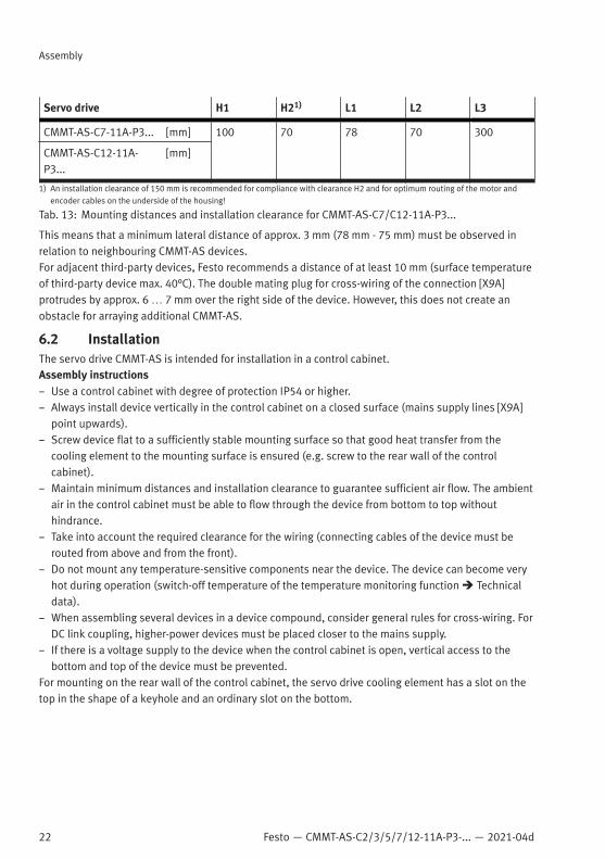
Servo drive H1 H21) L1 L2 L3
CMMT-AS-C7-11A-P3... [mm] 100 70 78 70 300
CMMT-AS-C12-11A-P3...
[mm]
1) An installation clearance of 150 mm is recommended for compliance with clearance H2 and for optimum routing of the motor andencoder cables on the underside of the housing!
Tab. 13: Mounting distances and installation clearance for CMMT-AS-C7/C12-11A-P3...
This means that a minimum lateral distance of approx. 3 mm (78 mm - 75 mm) must be observed inrelation to neighbouring CMMT-AS devices.For adjacent third-party devices, Festo recommends a distance of at least 10 mm (surface temperatureof third-party device max. 40°C). The double mating plug for cross-wiring of the connection [X9A]protrudes by approx. 6 … 7 mm over the right side of the device. However, this does not create anobstacle for arraying additional CMMT-AS.
6.2 InstallationThe servo drive CMMT-AS is intended for installation in a control cabinet.Assembly instructions– Use a control cabinet with degree of protection IP54 or higher.– Always install device vertically in the control cabinet on a closed surface (mains supply lines [X9A]
point upwards).– Screw device flat to a sufficiently stable mounting surface so that good heat transfer from the
cooling element to the mounting surface is ensured (e.g. screw to the rear wall of the controlcabinet).
– Maintain minimum distances and installation clearance to guarantee sufficient air flow. The ambientair in the control cabinet must be able to flow through the device from bottom to top withouthindrance.
– Take into account the required clearance for the wiring (connecting cables of the device must berouted from above and from the front).
– Do not mount any temperature-sensitive components near the device. The device can become veryhot during operation (switch-off temperature of the temperature monitoring function è Technicaldata).
– When assembling several devices in a device compound, consider general rules for cross-wiring. ForDC link coupling, higher-power devices must be placed closer to the mains supply.
– If there is a voltage supply to the device when the control cabinet is open, vertical access to thebottom and top of the device must be prevented.
For mounting on the rear wall of the control cabinet, the servo drive cooling element has a slot on thetop in the shape of a keyhole and an ordinary slot on the bottom.
Festo — CMMT-AS-C2/3/5/7/12-11A-P3-... — 2021-04d
Installation
23
Assembly of the servo drive
WARNING
Danger of burns through hot escaping gases and hot surfaces.In case of error, incorrect wiring or incorrect polarity of the connections [X9A], [X9B] and [X6A], internalcomponents can be overloaded. High temperatures can develop and hot gases can be released.• Have an authorised electrician perform the installation according to the documentation.
WARNING
Danger of burns from hot housing surfaces.Metallic housing parts can accept high temperatures in operation. In particular, the braking resistorinstalled in the profile on the back side can become very hot.Contact with metal housing parts can cause burn injuries.• Do not touch metallic housing parts.• After the power supply is switched off, let the device cool off to room temperature.
• Mount the servo drive on the rear wall of the control cabinet with suitable screws while complyingwith the assembly instructions.
7 Installation7.1 Safety
WARNING
Risk of injury from electric shock.Contact with live parts at the power connections [X6A], [X9A] and [X9B] can result in severe injuries ordeath.• Do not pull out power supply plugs while live.• Before touching, wait at least 5 minutes after switching off the load voltage to allow the inter-
mediate circuit to discharge.
WARNING
Risk of injury from electric shock.The leakage current of the device to earth (PE) is > 3.5 mA AC or 10 mA DC. Touching the devicehousing if there is a fault can result in serious injuries or death.Before commissioning, also for brief measuring and test purposes:• Connect PE connection on the mains side at the following positions:
• Protective earth connection (earthing screw) of the housing• PE pin of the connection [X9A] (power supply)
The cross section of the PE conductors must be at least equal to the cross section of themains conductor L at [X9A].
• Connect motor cable to connection [X6A] and the shield of the motor cable on the front side to PEvia the shield clamp of the servo drive.
• Observe the regulations of EN 60204-1 for the protective earthing.

24 Festo — CMMT-AS-C2/3/5/7/12-11A-P3-... — 2021-04d
Installation
WARNING
Danger of burns through hot escaping gases and hot surfaces.In case of error, incorrect wiring or incorrect polarity of the connections [X9A], [X9B] and [X6A], internalcomponents can be overloaded. High temperatures can develop and hot gases can be released.• Have an authorised electrician perform the installation according to the documentation.
WARNING
Risk of injury from electric shock in the event of incomplete insulation at the power connections[X6A], [X9A] and [X9B].Before operating, plugging in or unplugging the operator unit CDSB or a connector from a hot-plug-capable interface, the following points must be fulfilled:• The conducting lines at the device are completely insulated.• The protective earthing (PE) and the shield connection are correctly connected to the device.• The housing is free of damage.
WARNING
Risk of injury due to overheating and electric shock with faulty live componentsClosing the branch-circuit protective device with faulty live components may cause fire or electricshock.• The opening of the branch-circuit protective device may be an indication that a fault current has
been interrupted. To reduce the risk of fire or electric shock, current-carrying parts and othercomponents of the controller should be examined and replaced if damaged. If burnout of thecurrent element of an overload relay occurs, the complete overload relay must be replaced.
7.2 Residual current protective deviceWARNING
Risk of injury from electric shock.This product can cause a DC current in the residual-current conductor in case of error. In cases wherea residual current device (RCD) or a residual current monitor (RCM) is used to protect against director indirect contact, only the type B kind of RCD or RCM is permitted on the power supply side of thisproduct.
The touch current in the protective earthing conductor can exceed an alternating current of 3.5 mAor a DC current of 10 mA. Always connect both protective earthing connections to the mains-side PEconnection, the PE pin of [X9A] and PE earthing screw on the housing. The minimum cross section ofthe protective earthing conductor must comply with the local safety regulations for protective earthingconductors for equipment with high leakage current.A residual current circuit breaker with 30 mA tripping current may be suitable for a separately wiredservo drive CMMT-AS, depending on the configuration. As a rule, residual current protective deviceswith a rated residual current > 30 mA are required for a device compound consisting of several servodrives.Festo recommends using a residual current protective device with a tripping delay, as high residualcurrents occur during switch-on. Residual current protective devices with a tripping delay preventunintended tripping during switch-on.
Festo — CMMT-AS-C2/3/5/7/12-11A-P3-... — 2021-04d
Installation
25
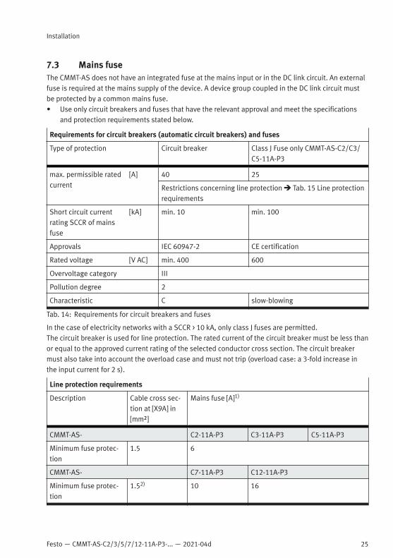
7.3 Mains fuseThe CMMT-AS does not have an integrated fuse at the mains input or in the DC link circuit. An externalfuse is required at the mains supply of the device. A device group coupled in the DC link circuit mustbe protected by a common mains fuse.• Use only circuit breakers and fuses that have the relevant approval and meet the specifications
and protection requirements stated below.
Requirements for circuit breakers (automatic circuit breakers) and fuses
Type of protection Circuit breaker Class J Fuse only CMMT-AS-C2/C3/C5-11A-P3
max. permissible ratedcurrent
[A] 40 25
Restrictions concerning line protection è Tab. 15 Line protectionrequirements
Short circuit currentrating SCCR of mainsfuse
[kA] min. 10 min. 100
Approvals IEC 60947-2 CE certification
Rated voltage [V AC] min. 400 600
Overvoltage category III
Pollution degree 2
Characteristic C slow-blowing
Tab. 14: Requirements for circuit breakers and fuses
In the case of electricity networks with a SCCR > 10 kA, only class J fuses are permitted.The circuit breaker is used for line protection. The rated current of the circuit breaker must be less thanor equal to the approved current rating of the selected conductor cross section. The circuit breakermust also take into account the overload case and must not trip (overload case: a 3-fold increase inthe input current for 2 s).
Line protection requirements
Description Cable cross sec-tion at [X9A] in[mm²]
Mains fuse [A]1)
CMMT-AS- C2-11A-P3 C3-11A-P3 C5-11A-P3
Minimum fuse protec-tion
1.5 6
CMMT-AS- C7-11A-P3 C12-11A-P3
Minimum fuse protec-tion
1.52) 10 16

26 Festo — CMMT-AS-C2/3/5/7/12-11A-P3-... — 2021-04d
Installation
Line protection requirements
Description Cable cross sec-tion at [X9A] in[mm²]
Mains fuse [A]1)
Maximum fuse protection of an individual device or a device group
without heat-resistantcable
4 25
6 32
with heat-resistantcable3)
4 32
6 40
1) Specifications according to DIN VDE 0298-4:2013, permissible currents according to EN 60204-1 may differ (depending on installa-tion type and temperature)
2) depending on the type of installation of the cables, wiring with min. 2.5 mm² may be required for the CMMT-AS-C12-11A-P3.3) no derating up to an ambient temperature of 50 °C and a cable temperature higher than 70 °C (max. cable temperature 90 °C)
Tab. 15: Line protection requirements
Fuse protection when load circuit is supplied with DC powerThe CMMT-AS allows the load circuit to be supplied with DC power. With DC power, external fuseprotection is once again required in the form of short circuit protection and line protection. The fusethat is used must be capable of reliably disconnecting the maximum DC supply voltage that couldoccur and the potential short circuit current (SCCRDC).Maximum fuse protection: 40 A
If fuse protection is to be avoided on the DC side, check whether the fuse protection could alterna-tively be installed on the AC side upstream of the DC fixed power supply.
7.4 Permissible and impermissible mains types of system earthingTN systems
TN systems Reference1) Information
TN-S system with sepa-rate neutral conductor andPE conductor in overallsystem
Fig. 31A1 System is supported.Connect device to the distribution network of the currentsource as follows:– Connect L1, L2, L3.– Do not connect N.For DC link coupling, connect only one device directly tothe distribution network of the current source. Connectthe coupled devices to the 3 mains phases using cross-wiring.2)
TN-S system with separateearthed mains conductorand PE conductor in overallsystem
Fig. 31A2 System is not supported because one phase is earthed.

Festo — CMMT-AS-C2/3/5/7/12-11A-P3-... — 2021-04d
Installation
27
TN systems Reference1) Information
TN-S system with earthedPE conductor without neu-tral conductor in overallsystem
Fig. 31A3 System is supported.Connect device to the distribution network of the currentsource as follows:– Connect L1, L2, L3.– Do not connect N.For DC link coupling, connect only one device directly tothe distribution network of the current source. Connectthe coupled devices to the 3 mains phases using cross-wiring.2)
TN-C system with neutralconductor and protectiveearth function combined ina single conductor, the PENconductor.
Fig. 31C System is supported.Connect device to the distribution network of the currentsource as follows:– Connect L1, L2, L3.– Use PEN as PE only.For DC link coupling, connect only one device directly tothe distribution network of the current source. Connectthe coupled devices to the 3 mains phases using cross-wiring.2)
TN-C-S system with neutralconductor and protectiveearth function combined ina single conductor, the PENconductor, in one part ofthe system
Fig. 31B1
1) è IEC 60364-1 Chapter 312.2.2) With cross-wiring, only 1 main switch and 1 circuit breaker is permissible for the device compound.
Tab. 16: Permissible and impermissible TN systems
TT system
TT system Reference1) Information
TT system with separateneutral conductor and PEconductor in the overallsystem.The N conductor is con-nected directly to the cur-rent source.
Fig. 31F1 System is supported.Connect device to the distribution network of the currentsource as follows:– Connect L1, L2, L3.– Use PEN as PE only.For DC link coupling, connect only one device directly tothe distribution network of the current source. Connectthe coupled devices to the 3 mains phases using cross-wiring.2)
1) è IEC 60364-1 Chapter 312.2.2) With cross-wiring, only 1 main switch and 1 circuit breaker is permissible for the device compound.
Tab. 17: TT system

28 Festo — CMMT-AS-C2/3/5/7/12-11A-P3-... — 2021-04d
Installation
IT system
IT system Reference1) Information
IT system with insulationof active parts separatedfrom protection earth orconnected via high impe-dance. The exposed con-ductive parts are con-nected to local earthing.
Fig. 31G1 System is supported.– The permissible system voltage of the CMMT-AS is
300 V in accordance with IEC 61800-5-1. Observe therestrictions set out in IEC 61800-5-1 when operatingthe CMMT-AS in an IT network!
– Use an insulation monitoring system so that insu-lation faults can be detected immediately (earth-leakage monitor).
– Interrupt the internal connection of the internal mainsfilter to PE è Interrupting the connection of theinternal mains filter to PE (for IT networks only).
– Use external filter measures that ensure CE con-formity.
Connect device to the distribution network of the currentsource as follows:– Connect L1, L2, L3.– Do not connect N.For DC link coupling, connect only one device directly tothe distribution network of the current source. Connectthe coupled devices to the 3 mains phases using cross-wiring.
1) è IEC 60364-1 Chapter 312.2.
Tab. 18: IT system
After removing the connection of the internal mains filter to PE, the device is not classified in respectof emitted interference in accordance with EN 61800-3. External filter measures are required.When operating servo drives in IT networks, the distributor must provide an EMC concept for theoverall system.This comprises as a minimum:– A concept for feedback of the converter leakage currents into the converter DC link circuit (Y
capacitors to the DC link circuit)– Use of external filter measures such as mains filter and converter output filterEarth-leakage monitorFor IT systems, an earth-leakage monitor is required so that an insulation fault between the mainsphase and PE can be detected immediately. An insulation fault must be rectified immediately afterdetection.Leakage currents in IT systemsHigh-frequency leakage currents to protective earthing (PE) may be encountered even in IT systems(IT = Isolé Terre) during operation of the servo drive. The leakage currents flow to the PE throughthe coupling capacitances of the motor cable and the motor and back to the servo drive through the
Festo — CMMT-AS-C2/3/5/7/12-11A-P3-... — 2021-04d
Installation
29
coupling capacitance of the isolating transformer via the load supply. The coupling capacitances canbe minimised by selection of a suitable isolating transformer and keeping the motor cable as short aspossible.
WARNING
Risk of injury from electric shock.The servo drive generates high-frequency leakage currents, which can lead to dangerous contactcurrents on the external conductors and the neutral conductor of the IT system. Touching the mainsconductor or the neutral conductor can result in serious injuries or death.• Before working on the IT systems, disconnect the servo drive from the mains.
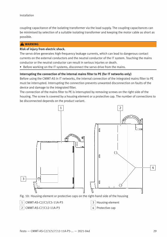
Interrupting the connection of the internal mains filter to PE (for IT networks only)Before using the CMMT-AS in IT networks, the internal connection of the integrated mains filter to PEmust be interrupted. Interrupting the connection prevents unwanted disconnection on faults of thedevice and damage to the integrated filter.The connection of the mains filter to PE is interrupted by removing screws on the right side of thehousing. The screw is covered by a housing element or a protective cap. The number of connections tobe disconnected depends on the product variant.
1 2
3
4
Fig. 10: Housing element or protective caps on the right-hand side of the housing
1 CMMT-AS-C2/C3/C5-11A-P3
2 CMMT-AS-C7/C12-11A-P3
3 Housing element
4 Protective cap
30 Festo — CMMT-AS-C2/3/5/7/12-11A-P3-... — 2021-04d
Installation
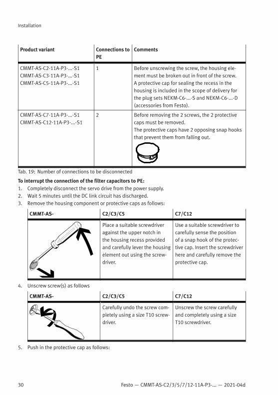
Product variant Connections toPE
Comments
CMMT-AS-C2-11A-P3-...-S1CMMT-AS-C3-11A-P3-...-S1CMMT-AS-C5-11A-P3-...-S1
1 Before unscrewing the screw, the housing ele-ment must be broken out in front of the screw.A protective cap for sealing the recess in thehousing is included in the scope of delivery forthe plug sets NEKM-C6-...-S and NEKM-C6-...-D(accessories from Festo).
CMMT-AS-C7-11A-P3-...-S1CMMT-AS-C12-11A-P3-...-S1
2 Before removing the 2 screws, the 2 protectivecaps must be removed.The protective caps have 2 opposing snap hooksthat prevent them from falling out.
Tab. 19: Number of connections to be disconnected
To interrupt the connection of the filter capacitors to PE:1. Completely disconnect the servo drive from the power supply.2. Wait 5 minutes until the DC link circuit has discharged.3. Remove the housing component or protective caps as follows:
CMMT-AS- C2/C3/C5 C7/C12
Place a suitable screwdriveragainst the upper notch inthe housing recess providedand carefully lever the housingelement out using the screw-driver.
Use a suitable screwdriver tocarefully sense the positionof a snap hook of the protec-tive cap. Insert the screwdriverhere and carefully remove theprotective cap.
4. Unscrew screw(s) as follows
CMMT-AS- C2/C3/C5 C7/C12
Carefully undo the screw com-pletely using a size T10 screw-driver.
Unscrew the screw carefullyand completely using a sizeT10 screwdriver.
5. Push in the protective cap as follows:

Festo — CMMT-AS-C2/3/5/7/12-11A-P3-... — 2021-04d
Installation
31
CMMT-AS- C2/C3/C5 C7/C12
Push the protective cap fullyinto the housing recess ascontact protection.
Push both protective capsback fully into the housingrecesses as contact protec-tion.
For operation in other networks:– Restore the internal connection of the mains filter to PE by screwing in the screw(s)– Tightening torque 1.4 Nm ± 15 %.
7.5 Connection of the mains side PE conductorAll PE conductors must always be connected prior to commissioning for safety reasons. Observe theregulations of EN 60204-1 when implementing protective earthing.Always connect PE connection on the mains side (PE rail in the control cabinet) at the followingpositions:– PE pin of the connection [X9A]– PE connection (earthing screw) next to the upper slot of the cooling elementThe cross section of the PE conductors must be at least equal to the cross section of the mainsconductors L at [X9A]. Wire individually wired devices in a star shape. Observe the requirements forcross-wiring for cross-wired devices. Recommendation: use copper earthing strap (advantageous forEMC).1. Equip PE conductors for the earthing screw with a suitable cable lug.2. Tighten earthing screw with a TORX screwdriver of size T20 (tightening torque 1.8 Nm ± 15 %).
1
Fig. 11: PE connection (earthing screw)
1 PE connection (earthing screw)
7.6 Information on EMC-compliant installationA mains filter is integrated into the device. The mains filter fulfils the following tasks:– Guarantees the device’s immunity to interference– Limits the conducted emissions of the deviceThe device fulfills the requirements of the relevant product standard EN 61800-3 with suitable installa-tion and wiring of all connecting cables.

32 Festo — CMMT-AS-C2/3/5/7/12-11A-P3-... — 2021-04d
Installation
The category that the device fulfils is dependent on the filter measures used and the motor cablelength. The integrated mains filter is designed so the device fulfils the following categories whenoperated as an individual device:
CMMT-AS... PWM[kHz]
required measures Max. permissible motor cablelength [m]
Category C2: operation in the first environment (residential area)
-C2-11A-P3 8 Line choke 10
-C3-11A-P3-C5-11A-P3
8 – (none) 10
-C7-11A-P3-C12-11A-P3
8 – (none) 10
Category C3: operation in the second environment (industrial area)
-C2-11A-P3-C3-11A-P3-C5-11A-P3
8 – (none) 50
external mains filter 100
-C7-11A-P3-C12-11A-P3
8 – (none) 25
external mains filter 100
Tab. 20: Category according to the cable length
Required measures
Measures Description
Line choke(3 x ³3.7 mH)
A line choke with three partial windings must be installed for mains supply linesL1, L2 and L3 (3 x ³ 3.7 mH) to comply with the mains harmonics requirementsin accordance with EN 61000-3-2 – accessories.
External mainsfilter
Install a suitable external mains filter - Accessories.
Tab. 21: Installation measures to achieve the specified category
For installation of a line choke on the CMMT-AS-C2-11A è 7.7 Connection examples.– If set-up and commissioning are performed by a professional with the necessary experience for
setting up and commissioning drive systems, including their EMC aspects, category C2 devices canbe used in the first environment (residential area).
– For operation of category C2 devices, limit values for the harmonic currents in the network(EN 61000-3-2 or EN 61000-3-12) apply, depending on the connected load of the machine. Pleasecheck whether this is the case for your facility/system. As a rule, compliance with the limit valuesfor harmonic currents requires the use of external filter measures, e.g. installation of a line choke.
– Category C3 devices are intended for use in the second environment only (industrial environment).Use in the first environment is not permitted.
This product can generate high frequency interference, which may make it necessary to implementinterference suppression measures in residential areas.

Festo — CMMT-AS-C2/3/5/7/12-11A-P3-... — 2021-04d
Installation
33
In practice, the combination of the components used and their characteristics influence the achievablelength of the motor cable. Examples for determining possible motor cable lengths with Festo motorsè 10.4.1 Cable lengths in combination with Festo motors.Cable lengths and cable shield– Only use suitable cables that fulfil the requirements of standard EN 60204-1.– Observe the max. permissible cable lengths and requirements for shielding.– Observe shield support requirements.
Connection Max. cable length [m] Cable shield
[X1A] Inputs/outputs for thehigher-order PLC
3 Unshielded
[X1C] Inputs/outputs for the axis 1001) unshielded/shielded2)
[X2] Encoder 1 1003) shielded
[X3] Encoder 2
[X6A] Motor phase connection Dependent on categoryè Tab. 20 Category accordingto the cable length
shielded
[X6B] Motor auxiliary connection 1001) shielded
[X9A] Power supply and DC linkcircuit connection
Single device: 2Device compound: 0.5
Unshielded
[X9B] Braking resistor 24) shielded4)
[X9C] Logic voltage supply Single device: 2Device compound: 0.5
Unshielded
[X10] Device synchronisation Single device: 3Device compound: 0.5
double shielded (CAT 5)
[X19] RTE (port 1 and port 2) 30 double shielded (CAT 5)
[X18] Standard Ethernet 30 double shielded (CAT 5)
1) Take voltage drop in the cables into account for cable lengths > 25 m by selecting suitable cross-sections for the insulated wires.2) Use a shielded cable outside the control cabinet for safety engineering applications. Otherwise, a shield is not absolutely essential,
but is recommended.3) Comply with the maximum permissible cable length for the installed encoder.4) with connection of an external braking resistor
Tab. 22: Cable lengths and cable shield
Shielded cables without a shielded plug housing have short unshielded cable ends at both ends bydefinition.Make unshielded cable ends as short as possible.Maximum permissible length of unshielded wires at the connection:– [X6A] max. 120 mm– [X6B] max. 150 mm– [X1C] max. 150 mm
34 Festo — CMMT-AS-C2/3/5/7/12-11A-P3-... — 2021-04d
Installation
Laying cablesComply with general guidelines for EMC-compliant installation, e.g.:– Do not run signal cables parallel to power cables.– Comply with required minimum distances between signal cables and power cables dependent on
the installation conditions. Signal cables must be physically separated from the power cables to themaximum possible extent.
– Avoid crossing signal cables with power cables or running them at a 90° angle in relation to oneanother.
EMC-compliant installation of the motor cable and encoder cables– Keep motor cable as short as possible to minimise the leakage currents and losses in the motor
cable.– Connect the motor cable shield under the shield clamp in the lower area on the front of the housing,
ensuring a large-area connection. The motor cable shield must be connected to the associatedservo drive so that the leakage currents can flow back into the servo drive from which theyoriginate.
– Connect the PE inner conductor of the motor cable to the PE connection point of the motorconnection [X6A].
– Connect the shield of the motor cable to the PE over a large surface area on the motor side (e.g. viathe shield connection provided on the motor connector or the shield support surface in the motorjunction box).
– If separate cables are used for the holding brake and the temperature sensor, connect the respec-tive shield to the corresponding PE connection point of the motor auxiliary connection [X6B].
– Connect the shield of the encoder cable on both sides: on the device side to the respective plughousing, on the motor side to the encoder or plug housing.
– Route the signal cables [X2], [X3], [X10], [X1C] and [X6B] downward and ensure strain relief usingcable binders at the cut-outs of the servo drive shield clamp.

Festo — CMMT-AS-C2/3/5/7/12-11A-P3-... — 2021-04d
Installation
35
7.7 Connection examplesConnection plan, 3-phase mains connection
1
4
2
3
5
6
7
Fig. 12: Connection example
1 Braking resistor
2 Circuit breaker or 3 x fuses
3 Main switch/main contactor
4 Line choke if required (for category C2)
5 PELV fixed power supply for 24 V supply
6 Encoder 2 (optional)
7 Encoder 1

36 Festo — CMMT-AS-C2/3/5/7/12-11A-P3-... — 2021-04d
Installation
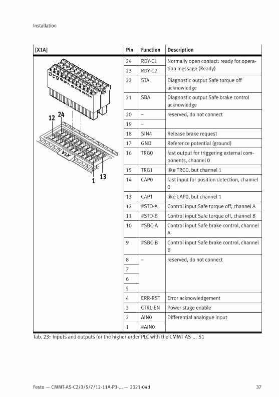
7.8 Interfaces7.8.1 [X1A], inputs and outputs for the higher-order PLC
The I/O interface [X1A] is located on the top of the device. This interface offers access to functionaland safety-related inputs and outputs of the device. These include, for example:– Digital inputs for 24 V level (PNP logic)– Digital outputs for 24 V level (PNP logic)– Signal contact for safety chain (RDY-C1, RDY-C2)– Differential analogue input ±10 V control voltageThe inputs and outputs of this I/O interface are used for coupling to a higher-order PLC. The safety-related inputs and outputs are connected to a safety relay unit.
Festo — CMMT-AS-C2/3/5/7/12-11A-P3-... — 2021-04d
Installation
37
[X1A] Pin Function Description
24 RDY-C1 Normally open contact: ready for opera-tion message (Ready)23 RDY-C2
22 STA Diagnostic output Safe torque offacknowledge
21 SBA Diagnostic output Safe brake controlacknowledge
20 – reserved, do not connect
19 –
18 SIN4 Release brake request
17 GND Reference potential (ground)
16 TRG0 fast output for triggering external com-ponents, channel 0
15 TRG1 like TRG0, but channel 1
14 CAP0 fast input for position detection, channel0
13 CAP1 like CAP0, but channel 1
12 #STO-A Control input Safe torque off, channel A
11 #STO-B Control input Safe torque off, channel B
10 #SBC-A Control input Safe brake control, channelA
9 #SBC-B Control input Safe brake control, channelB
8 – reserved, do not connect
7
6
5
4 ERR-RST Error acknowledgement
3 CTRL-EN Power stage enable
2 AIN0 Differential analogue input
1 #AIN0
Tab. 23: Inputs and outputs for the higher-order PLC with the CMMT-AS-...-S1

38 Festo — CMMT-AS-C2/3/5/7/12-11A-P3-... — 2021-04d
Installation
Requirements for the mating plugs (2 required)
Design FMC-1.5/12-ST-3.5 from Phoenix Contact or com-patible
Signal contacts 12 (12-pin, 1-row)
Nominal current 8 A
Rated voltage (III/2) 160 V
Pitch 3.5 mm
Strip length 10 mm
Tab. 24: Requirements for the mating plugs
Requirements for the connecting cable Single device Device compound
Shielding Unshielded
Min. conductor cross section incl.wire end sleeve with plastic sleeve
0.25 mm2 –
Max. conductor cross section incl. plasticwire end sleeve
0.75 mm2 –
Min. conductor cross section incl. doublewire end sleeve with plastic sleeve
– 0.25 mm2
Max. conductor cross section incl. doublewire end sleeve with plastic sleeve
– 0.5 mm2
Max. length 3 m 0.5 m
Tab. 25: Requirements for the connecting cable
Brief description of inputs and outputs at the connection [X1A] with the CMMT-AS-...-S1
Signalname
Name Function can beparame-terised
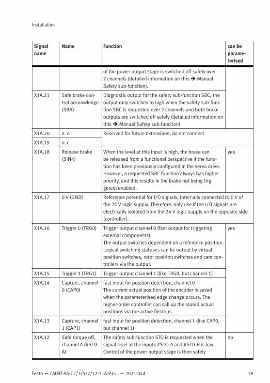
X1A.24 Ready 1 (RDY-C1) Normally open contact; readyIf the device is ready for operation, the contact isclosed. If there is an error, the contact is opened.
no
X1A.23 Ready 2 (RDY-C2)
X1A.22 Safe torque offacknowledge(STA)
Diagnostic output for the safety sub-function STO; theoutput only switches to high when the safety sub-func-tion STO is requested over 2 channels and the control
Festo — CMMT-AS-C2/3/5/7/12-11A-P3-... — 2021-04d
Installation
39
Signalname
Name Function can beparame-terised
of the power output stage is switched off safely over2 channels (detailed information on this è ManualSafety sub-function).
X1A.21 Safe brake con-trol acknowledge(SBA)
Diagnostic output for the safety sub-function SBC; theoutput only switches to high when the safety sub-func-tion SBC is requested over 2 channels and both brakeoutputs are switched off safely (detailed information onthis è Manual Safety sub-function).
X1A.20 n. c. Reserved for future extensions; do not connect
X1A.19 n. c.
X1A.18 Release brake(SIN4)
When the level at this input is high, the brake canbe released from a functional perspective if the func-tion has been previously configured in the servo drive.However, a requested SBC function always has higherpriority, and this results in the brake not being trig-gered/enabled.
yes
X1A.17 0 V (GND) Reference potential for I/O signals; internally connected to 0 V ofthe 24 V logic supply. Therefore, only use if the I/O signals areelectrically isolated from the 24 V logic supply on the opposite side(controller).
X1A.16 Trigger 0 (TRG0) Trigger output channel 0 (fast output for triggeringexternal components)The output switches dependent on a reference position.Logical switching statuses can be output by virtualposition switches, rotor position switches and cam con-trollers via the output.
yes
X1A.15 Trigger 1 (TRG1) Trigger output channel 1 (like TRG0, but channel 1)
X1A.14 Capture, channel0 (CAP0)
fast input for position detection, channel 0The current actual position of the encoder is savedwhen the parameterised edge change occurs. Thehigher-order controller can call up the stored actualpositions via the active fieldbus.
X1A.13 Capture, channel1 (CAP1)
fast input for position detection, channel 1 (like CAP0,but channel 1)
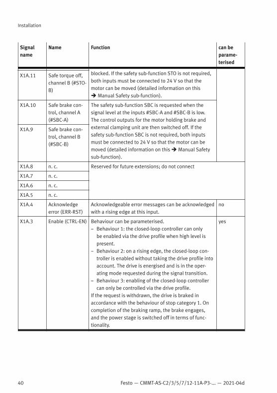
X1A.12 Safe torque off,channel A (#STO-A)
The safety sub-function STO is requested when thesignal level at the inputs #STO-A and #STO-B is low.Control of the power output stage is then safely
no
40 Festo — CMMT-AS-C2/3/5/7/12-11A-P3-... — 2021-04d
Installation
Signalname
Name Function can beparame-terised
blocked. If the safety sub-function STO is not required,both inputs must be connected to 24 V so that themotor can be moved (detailed information on thisè Manual Safety sub-function).
X1A.11 Safe torque off,channel B (#STO-B)
X1A.10 Safe brake con-trol, channel A(#SBC-A)
The safety sub-function SBC is requested when thesignal level at the inputs #SBC-A and #SBC-B is low.The control outputs for the motor holding brake andexternal clamping unit are then switched off. If thesafety sub-function SBC is not required, both inputsmust be connected to 24 V so that the motor can bemoved (detailed information on this è Manual Safetysub-function).
X1A.9 Safe brake con-trol, channel B(#SBC-B)
X1A.8 n. c. Reserved for future extensions; do not connect
X1A.7 n. c.
X1A.6 n. c.
X1A.5 n. c.
X1A.4 Acknowledgeerror (ERR-RST)
Acknowledgeable error messages can be acknowledgedwith a rising edge at this input.
no
X1A.3 Enable (CTRL-EN) Behaviour can be parameterised.– Behaviour 1: the closed-loop controller can only
be enabled via the drive profile when high level ispresent.
– Behaviour 2: on a rising edge, the closed-loop con-troller is enabled without taking the drive profile intoaccount. The drive is energised and is in the oper-ating mode requested during the signal transition.
– Behaviour 3: enabling of the closed-loop controllercan only be controlled via the drive profile.
If the request is withdrawn, the drive is braked inaccordance with the behaviour of stop category 1. Oncompletion of the braking ramp, the brake engages,and the power stage is switched off in terms of func-tionality.
yes

Festo — CMMT-AS-C2/3/5/7/12-11A-P3-... — 2021-04d
Installation
41
Signalname
Name Function can beparame-terised
X1A.2 AIN0 Differential analogue input for typical input level of± 10 VVia the analogue input, the following setpoint valuesand limits can be specified in the form of analoguevoltage:– Setpoint values for position, speed or force/current– Limits for speed or force/current
yes
X1A.1 #AIN0
Tab. 26: Inputs and outputs at the connection [X1A]
Internal design of digital inputs (DIN) – does not apply to STO inputsThe following equivalent circuit shows an example of the internal design of a digital input (DIN).The digital inputs are designed for +24 V level corresponding to type 3 in accordance with EN 61131-2.The digital inputs are not electrically isolated and have integrated EMC protective functions.Two-channel safe inputs correspond in their internal design to two 1-channel inputs. However, theequivalent circuit is not valid for the STO inputs. Information on 2-channel safe inputs è ManualSafety sub-function.
µCDIN
Fig. 13: Internal design of digital inputs (DIN)
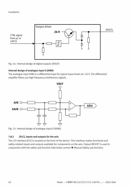
Internal design of digital outputs (DOUT)The digital outputs TRG0 and TRG1 supply + +24 V signals, which are implemented with a high-sidedriver.
42 Festo — CMMT-AS-C2/3/5/7/12-11A-P3-... — 2021-04d
Installation
Fig. 14: Internal design of digital outputs (DOUT)
Internal design of analogue input 0 (AIN0)The analogue input AIN0 is a differential input for typical input levels of ± 10 V. The differentialamplifier filters out high-frequency interference signals.
AIN
VREF
ADU
#AIN
Fig. 15: Internal design of analogue input 0 (AIN0)
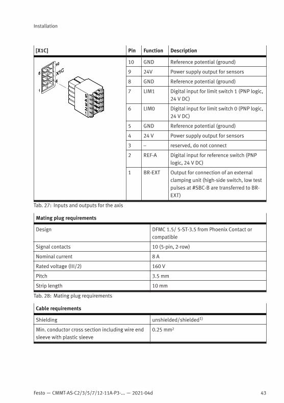
7.8.2 [X1C], inputs and outputs for the axis
The I/O interface [X1C] is located on the front of the device. This interface makes functional andsafety-related inputs and outputs available for components on the axis. Output BR-EXT is used inconjunction with the safety sub-function Safe brake control è Manual Safety sub-function.
Festo — CMMT-AS-C2/3/5/7/12-11A-P3-... — 2021-04d
Installation
43
[X1C] Pin Function Description
10 GND Reference potential (ground)
9 24V Power supply output for sensors
8 GND Reference potential (ground)
7 LIM1 Digital input for limit switch 1 (PNP logic,24 V DC)
6 LIM0 Digital input for limit switch 0 (PNP logic,24 V DC)
5 GND Reference potential (ground)
4 24 V Power supply output for sensors
3 – reserved, do not connect
2 REF-A Digital input for reference switch (PNPlogic, 24 V DC)
1 BR-EXT Output for connection of an externalclamping unit (high-side switch, low testpulses at #SBC-B are transferred to BR-EXT)
Tab. 27: Inputs and outputs for the axis
Mating plug requirements
Design DFMC 1.5/ 5-ST-3.5 from Phoenix Contact orcompatible
Signal contacts 10 (5-pin, 2-row)
Nominal current 8 A
Rated voltage (III/2) 160 V
Pitch 3.5 mm
Strip length 10 mm
Tab. 28: Mating plug requirements
Cable requirements
Shielding unshielded/shielded1)
Min. conductor cross section including wire endsleeve with plastic sleeve
0.25 mm2

44 Festo — CMMT-AS-C2/3/5/7/12-11A-P3-... — 2021-04d
Installation
Cable requirements
Max. conductor cross section including wire endsleeve with plastic sleeve
0.75 mm2
Max. length 100 m
1) Use a shielded cable outside the control cabinet for safety engineering applications. Otherwise, a shield is not absolutely essential,but is recommended.
Tab. 29: Cable requirements
Shield support requirementsConnecting the shield1. On the device side, connect the cable shield to the shield clamp for the motor cable.2. On the machine side, connect the cable shield to an earthed machine part.
7.8.3 [X2], encoder interface 1
The encoder interface [X2] is located on the front of the device. The encoder interface [X2] is primarilydesigned for connecting the position encoder integrated into the motor.
Supported standards/protocols Supported encoders
Hiperface SEK/SEL 37SKS/SKM 36
EnDat 2.2 ECI 1118/EBI 1135ECI 1119/EQI 1131ECN 1113/EQN 1125ECN 1123/EQN 1135
EnDat 2.1 Only in conjunction with Festo motors fromthe series EMMS-AS that have an inte-grated encoder with EnDat 2.1 protocol
Digital incremental encoders with square-wave signalsand with RS422-compatible signal output (differentialA, B, N signals)
ROD 426 or compatible
Analogue SIN/COS incremental encoders with differen-tial analogue signals with 1 Vss
HEIDENHAIN LS 187/LS 487 (20 µm signalperiod) or compatible
Encoders with asynchronous two-wire communicationinterface (RS485)
Nikon MAR-M50A or compatible (18 bitdata frames)
Tab. 30: Standards and protocols supported by the encoder interface [X2]
NOTICEDamage to the sensor when sensor type is changed.The servo drive can provide 5 V or 10 V sensor supply. Through configuration of the sensor, the supplyvoltage is established for the sensor. The sensor can be damaged if the configuration is not adjustedbefore connection of another sensor type.• When changing the sensor type: Comply with specified steps.
Festo — CMMT-AS-C2/3/5/7/12-11A-P3-... — 2021-04d
Installation
45
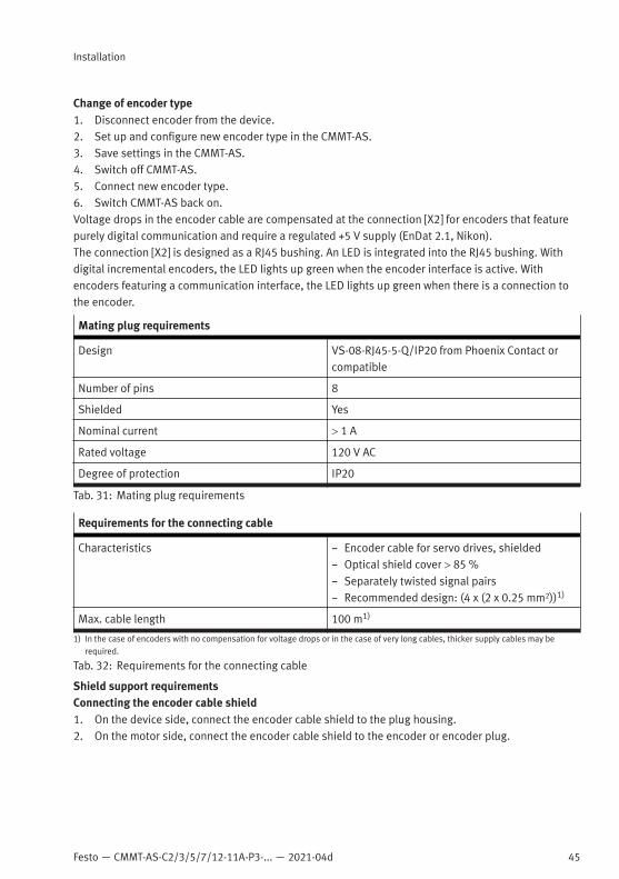
Change of encoder type1. Disconnect encoder from the device.2. Set up and configure new encoder type in the CMMT-AS.3. Save settings in the CMMT-AS.4. Switch off CMMT-AS.5. Connect new encoder type.6. Switch CMMT-AS back on.Voltage drops in the encoder cable are compensated at the connection [X2] for encoders that featurepurely digital communication and require a regulated +5 V supply (EnDat 2.1, Nikon).The connection [X2] is designed as a RJ45 bushing. An LED is integrated into the RJ45 bushing. Withdigital incremental encoders, the LED lights up green when the encoder interface is active. Withencoders featuring a communication interface, the LED lights up green when there is a connection tothe encoder.
Mating plug requirements
Design VS-08-RJ45-5-Q/IP20 from Phoenix Contact orcompatible
Number of pins 8
Shielded Yes
Nominal current > 1 A
Rated voltage 120 V AC
Degree of protection IP20
Tab. 31: Mating plug requirements
Requirements for the connecting cable
Characteristics – Encoder cable for servo drives, shielded– Optical shield cover > 85 %– Separately twisted signal pairs– Recommended design: (4 x (2 x 0.25 mm2))1)
Max. cable length 100 m1)
1) In the case of encoders with no compensation for voltage drops or in the case of very long cables, thicker supply cables may berequired.
Tab. 32: Requirements for the connecting cable
Shield support requirementsConnecting the encoder cable shield1. On the device side, connect the encoder cable shield to the plug housing.2. On the motor side, connect the encoder cable shield to the encoder or encoder plug.

46 Festo — CMMT-AS-C2/3/5/7/12-11A-P3-... — 2021-04d
Installation
Pin allocation of EnDat encoder (EnDat 2.1 and EnDat 2.2)
[X2] Pin Function Value Description
1 SCLK 5 Vss, Ri = 120 W Clock line, output,RS485-compliant,differential
2 #SCLK
3 VCC-IN Measured value Only for EnDat 2.1:encoder voltageback measurement,differential
4 DATA Differential signal:5 Vss, Ri = 120 W
Data cable, bidirec-tional, RS485-com-pliant, differential
5 #DATA
6 #VCC-IN Measured value Only for EnDat 2.1:encoder voltageback measurement,differential, inverse
7 VCC1 – EnDat 2.1:5.00 V … 5.50 V,max. 250 mA
– EnDat 2.2:9.50 V … 10.50 V,max. 250 mA
Encoder supply,switchable– EnDat 2.1: 5 V– EnDat 2.2: 10 V
8 GND 0 V Reference potentialof encoder supply
Housing FE, connected to PE – The housing is usedas a support for thecable shield and isconnected to the PE.
Tab. 33: EnDat encoder
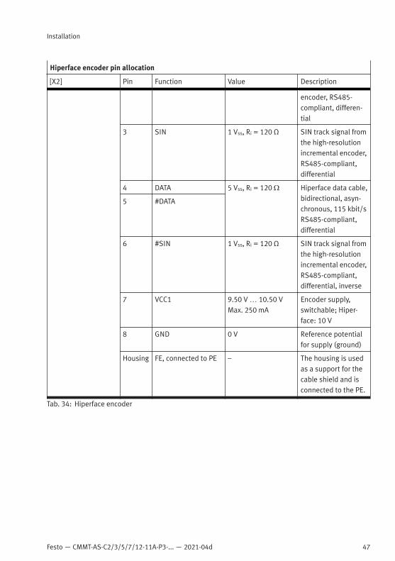
Hiperface encoder pin allocation
[X2] Pin Function Value Description
1 COS 1 Vss, Ri = 120 W COS track signalfrom the high-reso-lution incremental
2 #COS
Festo — CMMT-AS-C2/3/5/7/12-11A-P3-... — 2021-04d
Installation
47
Hiperface encoder pin allocation
[X2] Pin Function Value Description
encoder, RS485-compliant, differen-tial
3 SIN 1 Vss, Ri = 120 Ω SIN track signal fromthe high-resolutionincremental encoder,RS485-compliant,differential
4 DATA 5 Vss, Ri = 120 W Hiperface data cable,bidirectional, asyn-chronous, 115 kbit/sRS485-compliant,differential
5 #DATA
6 #SIN 1 Vss, Ri = 120 Ω SIN track signal fromthe high-resolutionincremental encoder,RS485-compliant,differential, inverse
7 VCC1 9.50 V … 10.50 VMax. 250 mA
Encoder supply,switchable; Hiper-face: 10 V
8 GND 0 V Reference potentialfor supply (ground)
Housing FE, connected to PE – The housing is usedas a support for thecable shield and isconnected to the PE.
Tab. 34: Hiperface encoder

48 Festo — CMMT-AS-C2/3/5/7/12-11A-P3-... — 2021-04d
Installation
Pin allocation for digital incremental encoders
[X2] Pin Function Value Description
1 A 5 Vss, Ri = 120 W A-track signalfrom the incre-mental encoder,RS485-compliant,differential
2 #A
3 B 5 Vss, Ri = 120 W B-track signalfrom the incre-mental encoder,RS485-compliant,differential
4 N 5 Vss, Ri = 120 W Zero pulse or N-track signal from theincremental encoder,RS485-compliant,differential
5 #N
6 #B 5 Vss, Ri = 120 W B-track signalfrom the incre-mental encoder,RS485-compliant,differential, inverse
7 VCC1 5.00 V … 5.50 V,max. 250 mA
Encoder supply,switchable; incre-mental encoder: 5 VVoltage drop in theencoder cable is notcompensated
8 GND 0 V Reference potentialfor supply (ground)
Housing FE, connected to PE – The housing is usedas a support for thecable shield and isconnected to the PE.
Tab. 35: Digital incremental encoders

Festo — CMMT-AS-C2/3/5/7/12-11A-P3-... — 2021-04d
Installation
49
Pin allocation for analogue SIN/COS incremental encoders
[X2] Pin Function Value Description
1 COS 1 Vss, Ri = 120 Ω COS track signalfrom the high-reso-lution incrementalencoder, RS485-compliant, differen-tial
2 #COS
3 SIN 1 Vss, Ri = 120 Ω SIN track signal fromthe high-resolutionincremental encoder,RS485-compliant,differential
4 N 5 Vss, Ri = 120 Ω Zero pulse or N-track signal from theincremental encoder,RS485-compliant,differential
5 #N
6 #SIN 1 Vss, Ri = 120 Ω SIN track signal fromthe high-resolutionincremental encoder,RS485-compliant,differential, inverse
7 VCC1 5.00 V … 5.50 V,max. 250 mA
Encoder supply,switchable; SIN/COSencoder: 5 VVoltage drop in theencoder cable is notcompensated
8 GND 0 V Reference potentialfor supply (ground)
Housing FE, connected to PE – The housing is usedas a support for thecable shield and isconnected to the PE.
Tab. 36: Analogue SIN/COS incremental encoders

50 Festo — CMMT-AS-C2/3/5/7/12-11A-P3-... — 2021-04d
Installation
Pin allocation for encoders with asynchronous communication interface
[X2] Pin Function Value Description
1 – – –
2 –
3 VCC-IN Measured value Encoder voltageback measurement,differential
4 DATA 5 Vss, Ri = 120 W Data cable,bidirectional, asyn-chronous, max.4000 kbit/s, RS485-compliant, differen-tial
5 #DATA
6 #VCC-IN Measured value Encoder voltageback measurement,differential, inverse
7 VCC1 5.00 V … 5.50 V,max. 250 mA
Encoder supply,switchable; 5 VVoltage drop in theencoder cable iscompensated
8 GND 0 V Reference potentialfor supply (ground)
Housing FE, connected to PE – The housing is usedas a support for thecable shield and isconnected to the PE.
Tab. 37: Encoders with asynchronous communication interface
7.8.4 [X3], encoder interface 2
The encoder interface [X3] is located on the front side of the device. The encoder interface [X3]primarily serves to connect a second position encoder to the axis (e.g. to enable precise positioningcontrol for the axis or as a redundant measuring system for safe motion monitoring).

Festo — CMMT-AS-C2/3/5/7/12-11A-P3-... — 2021-04d
Installation
51
Supported standards/protocols Supported encoders
Digital incremental encoders with square-wavesignals and with RS422-compatible signal out-puts (differential A, B, N signals)
ROD 426 or compatibleELGO LMIX 22
Analogue SIN/COS incremental encoders withdifferential analogue signals with 1 Vss
HEIDENHAIN LS 187/LS 487 (20 µm signalperiod) or compatible
Tab. 38: Standards and protocols supported by the encoder interface [X3]
[X3] is designed to be electrically compatible with [X2] but does not support all encoders and functionslike [X2].The connection [X3] is designed as an RJ45 bushing. An LED is integrated into the RJ45 bushing. TheLED indicates the connection status. If there is a connection to the encoder, the LED lights up green.
Mating plug requirements
Design VS-08-RJ45-5-Q/IP20 from Phoenix Contact orcompatible
Number of pins 8
Shielded Yes
Nominal current > 1 A
Rated voltage 120 V AC
Degree of protection IP20
Tab. 39: Mating plug requirements
Requirements for the connecting cable
Characteristics – Encoder cable for servo drives, shielded– Optical shield cover > 85 %– Separately twisted signal pairs– Recommended design: (4 x (2 x 0.25 mm2))1)
Max. cable length 100 m1)
1) In the case of encoders with no compensation for voltage drops or in the case of very long cables, thicker supply cables may berequired.
Tab. 40: Requirements for the connecting cable
Shield support requirementsConnecting the encoder cable shield1. On the device side, connect the encoder cable shield to the plug housing.2. On the motor side, connect the encoder cable shield to the encoder or encoder plug.
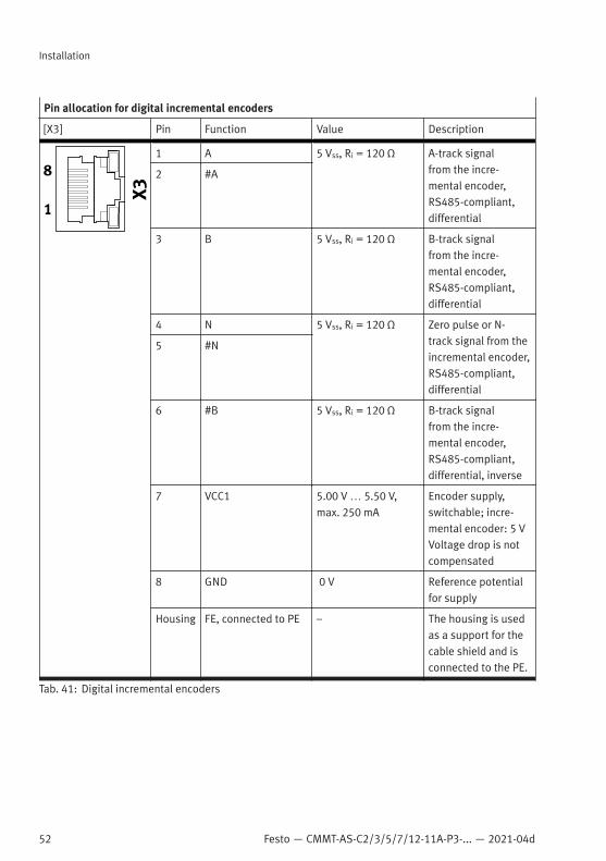
52 Festo — CMMT-AS-C2/3/5/7/12-11A-P3-... — 2021-04d
Installation
Pin allocation for digital incremental encoders
[X3] Pin Function Value Description
1 A 5 Vss, Ri = 120 Ω A-track signalfrom the incre-mental encoder,RS485-compliant,differential
2 #A
3 B 5 Vss, Ri = 120 Ω B-track signalfrom the incre-mental encoder,RS485-compliant,differential
4 N 5 Vss, Ri = 120 Ω Zero pulse or N-track signal from theincremental encoder,RS485-compliant,differential
5 #N
6 #B 5 Vss, Ri = 120 Ω B-track signalfrom the incre-mental encoder,RS485-compliant,differential, inverse
7 VCC1 5.00 V … 5.50 V,max. 250 mA
Encoder supply,switchable; incre-mental encoder: 5 VVoltage drop is notcompensated
8 GND 0 V Reference potentialfor supply
Housing FE, connected to PE – The housing is usedas a support for thecable shield and isconnected to the PE.
Tab. 41: Digital incremental encoders
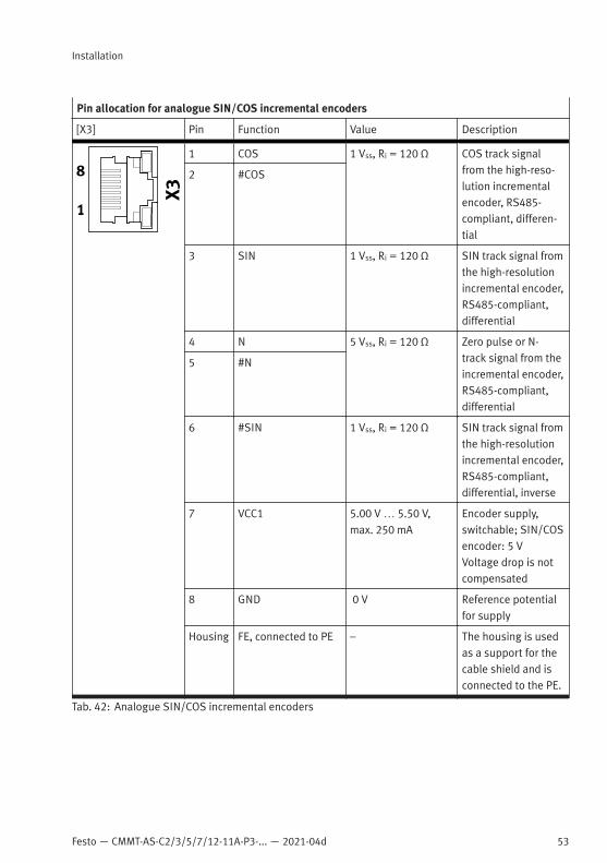
Festo — CMMT-AS-C2/3/5/7/12-11A-P3-... — 2021-04d
Installation
53
Pin allocation for analogue SIN/COS incremental encoders
[X3] Pin Function Value Description
1 COS 1 Vss, Ri = 120 Ω COS track signalfrom the high-reso-lution incrementalencoder, RS485-compliant, differen-tial
2 #COS
3 SIN 1 Vss, Ri = 120 Ω SIN track signal fromthe high-resolutionincremental encoder,RS485-compliant,differential
4 N 5 Vss, Ri = 120 Ω Zero pulse or N-track signal from theincremental encoder,RS485-compliant,differential
5 #N
6 #SIN 1 Vss, Ri = 120 Ω SIN track signal fromthe high-resolutionincremental encoder,RS485-compliant,differential, inverse
7 VCC1 5.00 V … 5.50 V,max. 250 mA
Encoder supply,switchable; SIN/COSencoder: 5 VVoltage drop is notcompensated
8 GND 0 V Reference potentialfor supply
Housing FE, connected to PE – The housing is usedas a support for thecable shield and isconnected to the PE.
Tab. 42: Analogue SIN/COS incremental encoders
54 Festo — CMMT-AS-C2/3/5/7/12-11A-P3-... — 2021-04d
Installation
7.8.5 [X10], SYNC IN/OUT
The interface [X10] is located on the front of the device. The interface [X10] permits master-slavecoupling. In the master-slave coupling, the axes of several devices (slave axes) are synchronised via adevice (master axis). The SYNC interface can be configured for different functions and can be used asfollows:
Possible functions Description
Incremental encoder output Output of a master axis that emulates encodersignals (encoder emulation)
Incremental encoder input Input of a slave axis for receiving the encodersignals of a master axis
Tab. 43: Possible functions of the connection [X10]
The connection [X10] is designed as an RJ45 bushing. An LED is integrated into the RJ45 bushing. TheLED shows whether the interface has been activated. If the interface has been activated, the LED isgreen. The CMMT-AS cannot detect whether an encoder is connected.
Mating plug requirements
Design VS-08-RJ45-5-Q/IP20 from Phoenix Contact orcompatible
Number of pins 8
Shielded yes
Nominal current > 1 A
Rated voltage 120 V AC
Degree of protection IP20
Tab. 44: Mating plug requirements
Requirements for the connecting cable
Characteristics – Encoder cable for servo drives, shielded– Optical shield cover > 85%– Separately twisted signal pairs– recommended design: (4 x (2 x 0.25 mm2))
Max. cable length 3 m
Tab. 45: Requirements for the connecting cable
Shield support requirementsConnect the connecting cable shield to the plug housings on both sides.
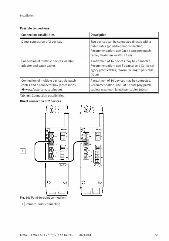
Festo — CMMT-AS-C2/3/5/7/12-11A-P3-... — 2021-04d
Installation
55
Possible connections
Connection possibilities Description
Direct connection of 2 devices Two devices can be connected directly with apatch cable (point-to-point connection).Recommendation: use Cat 5e category patchcable; maximum length: 25 cm
Connection of multiple devices via RJ45 Tadapter and patch cables
A maximum of 16 devices may be connected.Recommendation: use T adapter and Cat 5e cat-egory patch cables; maximum length per cable:25 cm
Connection of multiple devices via patchcables and a connector box (accessoriesè www.festo.com/catalogue)
A maximum of 16 devices may be connected.Recommendation: use Cat 5e category patchcables; maximum length per cable: 100 cm
Tab. 46: Connection possibilities
Direct connection of 2 devices
1
Fig. 16: Point-to-point connection
1 Point-to-point connection

56 Festo — CMMT-AS-C2/3/5/7/12-11A-P3-... — 2021-04d
Installation
Connection of multiple devices via RJ45 T adapter and patch cables
1
Fig. 17: Connection over RJ45 T adapter and patch cables
1 RJ45 T adapter
Connection of multiple devices via patch cables and a connector box
1
Fig. 18: Connection over a hub
1 Connection over a connector box
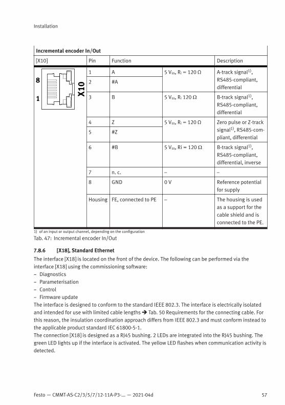
Festo — CMMT-AS-C2/3/5/7/12-11A-P3-... — 2021-04d
Installation
57
Incremental encoder In/Out
[X10] Pin Function Description
1 A 5 Vss, Ri = 120 Ω A-track signal1),RS485-compliant,differential
2 #A
3 B 5 Vss, Ri 120 Ω B-track signal1),RS485-compliant,differential
4 Z 5 Vss, Ri = 120 Ω Zero pulse or Z-tracksignal1), RS485-com-pliant, differential
5 #Z
6 #B 5 Vss, Ri = 120 Ω B-track signal1),RS485-compliant,differential, inverse
7 n. c. – –
8 GND 0 V Reference potentialfor supply
Housing FE, connected to PE – The housing is usedas a support for thecable shield and isconnected to the PE.
1) of an input or output channel, depending on the configuration
Tab. 47: Incremental encoder In/Out
7.8.6 [X18], Standard Ethernet
The interface [X18] is located on the front of the device. The following can be performed via theinterface [X18] using the commissioning software:– Diagnostics– Parameterisation– Control– Firmware updateThe interface is designed to conform to the standard IEEE 802.3. The interface is electrically isolatedand intended for use with limited cable lengths è Tab. 50 Requirements for the connecting cable. Forthis reason, the insulation coordination approach differs from IEEE 802.3 and must conform instead tothe applicable product standard IEC 61800-5-1.The connection [X18] is designed as a RJ45 bushing. 2 LEDs are integrated into the RJ45 bushing. Thegreen LED lights up if the interface is activated. The yellow LED flashes when communication activity isdetected.
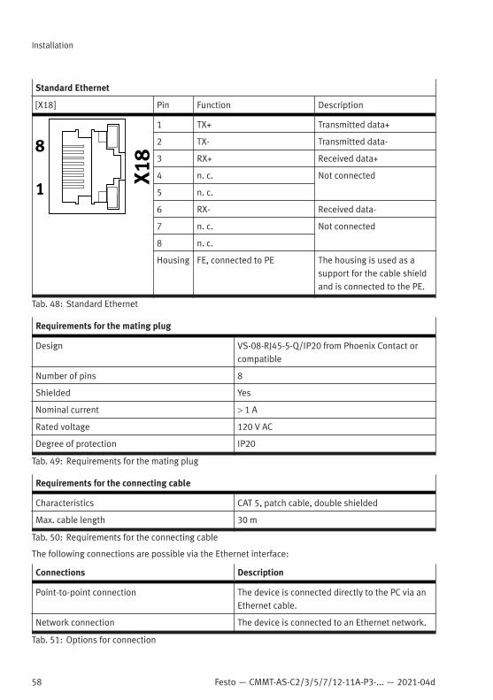
58 Festo — CMMT-AS-C2/3/5/7/12-11A-P3-... — 2021-04d
Installation
Standard Ethernet
[X18] Pin Function Description
1 TX+ Transmitted data+
2 TX- Transmitted data-
3 RX+ Received data+
4 n. c. Not connected
5 n. c.
6 RX- Received data-
7 n. c. Not connected
8 n. c.
Housing FE, connected to PE The housing is used as asupport for the cable shieldand is connected to the PE.
Tab. 48: Standard Ethernet
Requirements for the mating plug
Design VS-08-RJ45-5-Q/IP20 from Phoenix Contact orcompatible
Number of pins 8
Shielded Yes
Nominal current > 1 A
Rated voltage 120 V AC
Degree of protection IP20
Tab. 49: Requirements for the mating plug
Requirements for the connecting cable
Characteristics CAT 5, patch cable, double shielded
Max. cable length 30 m
Tab. 50: Requirements for the connecting cable
The following connections are possible via the Ethernet interface:
Connections Description
Point-to-point connection The device is connected directly to the PC via anEthernet cable.
Network connection The device is connected to an Ethernet network.
Tab. 51: Options for connection
Festo — CMMT-AS-C2/3/5/7/12-11A-P3-... — 2021-04d
Installation
59
The device supports the following methods of IP configuration (based on IPv4):
Methods Description
Obtain IP address automatically (DHCP client) The device obtains its IP configuration from aDHCP server in your network. This method is suit-able for networks in which a DHCP server alreadyexists.
Fixed IP configuration The device uses a fixed IP configuration.The IP configuration of the device can be perma-nently assigned manually. However, the devicecan only be addressed if the assigned IP configu-ration matches the IP configuration of the PC.Factory setting: 192.168.0.1
Tab. 52: Options for IP configuration
Shield connection requirements• Connect the cable shield to the plug housings on both sides.Possible connections• Connect CMMT to your network via a hub/switch or directly to the PC.
7.8.7 [X19], Real-time Ethernet (RTE) port 1 and port 2
The interface [X19] is located on the top of the device. The interface [X19] permits RTE communication.The following protocols are supported by the interface [X19], depending on the product design:
Product variant Supported protocol
CMMT-AS-...-EC EtherCAT
CMMT-AS-...-EP EtherNet/IP
CMMT-AS-...-PN PROFINET
Tab. 53: Supported protocol
The physical level of the interface fulfils the requirements according to IEEE 802.3. The interface iselectrically isolated and intended for use with limited cable lengths è Tab. 56 Requirements for theconnecting cable.The interface [X19] offers 2 ports.– Port 1, labelled on the device with [X19, XF1 IN]– Port 2, labelled on the device with [X19, XF2 OUT]2 LEDs are integrated into each of the two RJ45 bushings. The behaviour of the LEDs depends on thebus protocol. Use is not always made of both LEDs.

60 Festo — CMMT-AS-C2/3/5/7/12-11A-P3-... — 2021-04d
Installation
Real-time Ethernet (RTE) port 1 and port 2
[X19] Pin Function Description
1 TX+ Transmitted data+
2 TX- Transmitted data-
3 RX+ Received data+
4 n. c. Not connected
5 n. c.
6 RX- Received data-
7 n. c. Not connected
8 n. c.
Housing FE, connected to PE The housing is used as asupport for the cable shieldand is connected to the PE.
Tab. 54: [X19], RTE port 1 and port 2
Mating plug requirements
Design VS-08-RJ45-5-Q/IP20 from Phoenix Contact orcompatible
Number of pins 8
Shielded Yes
Nominal current > 1 A
Rated voltage 120 V AC
Degree of protection IP20
Tab. 55: Mating plug requirements
Requirements for the connecting cable
Characteristics CAT 5, patch cable, double shielded
Max. cable length 30 m
Tab. 56: Requirements for the connecting cable
Shield support requirements• Connect the cable shield to the plug housings on both sides.Connection to the controller• If possible, and if supported by the bus protocol, build ring redundancy into the connection with
the controller.
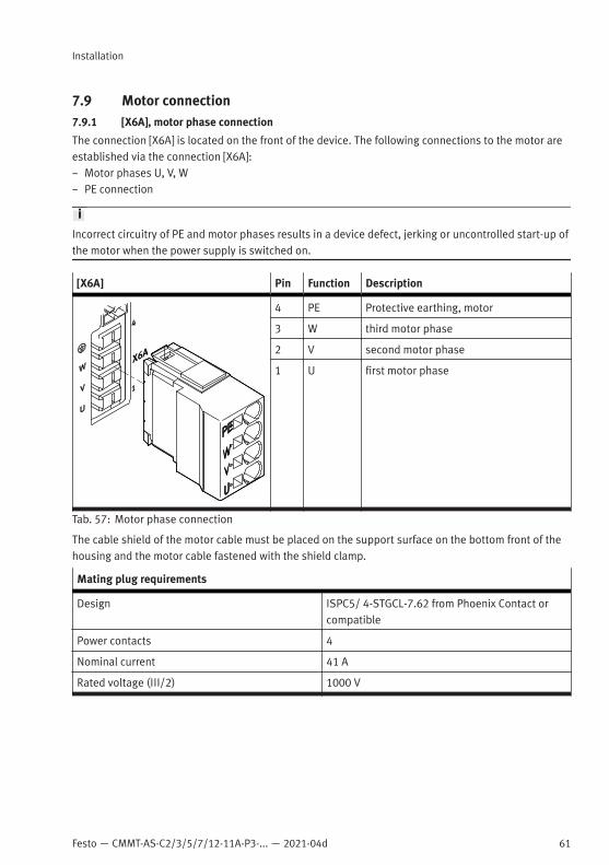
Festo — CMMT-AS-C2/3/5/7/12-11A-P3-... — 2021-04d
Installation
61
7.9 Motor connection7.9.1 [X6A], motor phase connection
The connection [X6A] is located on the front of the device. The following connections to the motor areestablished via the connection [X6A]:– Motor phases U, V, W– PE connection
Incorrect circuitry of PE and motor phases results in a device defect, jerking or uncontrolled start-up ofthe motor when the power supply is switched on.
[X6A] Pin Function Description
4 PE Protective earthing, motor
3 W third motor phase
2 V second motor phase
1 U first motor phase
Tab. 57: Motor phase connection
The cable shield of the motor cable must be placed on the support surface on the bottom front of thehousing and the motor cable fastened with the shield clamp.
Mating plug requirements
Design ISPC5/ 4-STGCL-7.62 from Phoenix Contact orcompatible
Power contacts 4
Nominal current 41 A
Rated voltage (III/2) 1000 V

62 Festo — CMMT-AS-C2/3/5/7/12-11A-P3-... — 2021-04d
Installation
Mating plug requirements
Pitch 7.62 mm
Strip length – for wire end sleeves with plastic sleeves:15 mm
– for wire end sleeves without plastic sleeves:10 mm
Tab. 58: Mating plug requirements
Requirements for the connecting cable
Wires and shielding – 4 power wires, shielded– Extra optional wires, e.g. for the holding brake
(shielded separately) and the motor tempera-ture sensor (shielded separately)
Structure Only use cables that ensure reinforced isolationbetween the motor phases and the shielded sig-nals of the holding brake and motor temperaturesensor in accordance with IEC 61800-5-1.è 7.9.4 Shield support of the motor cable
Max. cable length è 7.6 Information on EMC-compliant installation
Max. capacitance < 250 pF/m
Nominal cross section of power wires1)
CMMT-AS-C2/C3/C5-11A-P3CMMT-AS-C7-11A-P32)
0.75 mm2 … 1.5 mm2
CMMT-AS-C12-11A-P33) 1.5 mm2 … 2.5 mm2
Cable diameter of the stripped cable or shield sleeve (clamping range of the shield clamp)
CMMT-AS-C2/C3/C5-11A-P3 11 mm … 15 mm
CMMT-AS-C7/C12-11A-P3 12 mm … 17 mm
The only motor cables permitted are those that fulfil the requirements of EN 61800-5-2, Annex D.3.1and the requirements of EN 60204-1.
1) Shield clamp and mating connector also permit larger cross sections.2) for 0.75 mm² check that the shield diameter is sufficient for proper clamping3) 2.5 mm² is recommended for cable lengths over 50 m to limit the voltage loss of the available output voltage.
Tab. 59: Requirements for the connecting cable
Festo offers prefabricated motor cables as accessories è 3 Additional information.– Only use motor cables that have been approved for operation with the Festo servo drive. Motor
cables of other manufacturers are permitted if they meet the specified requirements.

Festo — CMMT-AS-C2/3/5/7/12-11A-P3-... — 2021-04d
Installation
63
7.9.2 [X6B], motor auxiliary connection
The connection [X6B] is located on the front of the device. The holding brake of the motor and themotor temperature sensor can be connected to the connection [X6B]. The output for the holding brakeis used both functionally and in connection with the safety sub-function Safe brake control è ManualSafety sub-function.To allow motor temperature monitoring, the following are supported:– N/C and N/O contacts– KTY 81 … 84 (silicon temperature sensors)– PTC (PTC resistor, positive temperature coefficient)– NTC (NTC resistor, negative temperature coefficient)– Pt1000 (platinum measuring resistor)The servo drive monitors whether the motor temperature violates an upper or lower limit. Withswitching sensors, only the upper limit value can be monitored (e.g. with a normally closed contact).The limit values and the error response can be parameterised.
[X6B] Pin Function Description
6 MT– Motor temperature (negative potential)
5 MT+ Motor temperature (positive potential)
4 FE Functional earth connected to protectiveearth
3 BR– Holding brake (negative potential)
2 BR+ Holding brake (positive potential)
1 FE Functional earth connected to protectiveearth
Tab. 60: Motor auxiliary connection
Mating plug requirements
Design DFMC 1.5/ 3-ST-3.5 from Phoenix Contact orcompatible
Signal contacts 6 (3-pin, 2-row)
Nominal current 8 A
Rated voltage (III/2) 160 V
Pitch 3.5 mm
Strip length 10 mm
Tab. 61: Mating plug requirements
64 Festo — CMMT-AS-C2/3/5/7/12-11A-P3-... — 2021-04d
Installation
Requirements for the connecting cable
Structure – 2 wires for the line to the holding brake,twisted in pairs, separately shielded
– 2 wires for the line to the temperature sensor,twisted in pairs, separately shielded
Min. conductor cross section including wire endsleeve with plastic sleeve
0.25 mm2
Max. conductor cross section including wire endsleeve with plastic sleeve
0.75 mm2
Max. length 100 m1)
1) Take voltage drop into account for cable lengths > 25 m by selecting suitable cross-sections for the insulated wires.
Tab. 62: Requirements for the connecting cable
Requirement for the temperature sensor in the motor– electrically reinforced isolation from the motor phases in accordance with IEC 61800-5-1, voltage
class C, overvoltage category III.Shield support requirements– Connect the cable shield on both sides.– Make unshielded cable ends as short as possible.
Length of unshielded cable ends
Product variant Recommended Max.
CMMT-AS-C2/C3/C5-11A-P3 150 mm 200 mm
CMMT-AS-C7/C12-11A-P3
Tab. 63: Recommended and maximum lengths of unshielded cable ends
7.9.3 Electronic overload and over temperature protection for the motor
The CMMT-AS allows the motor to be electronically protected against overload and provides overtemperature protection with the following protective functions:
Protective functions Description Measures required during installation andcommissioning
Temperature moni-toring of the motor
The motor temperature ismonitored for an upper andlower limit value, includinghysteresis. The limit valuescan be parameterised.
– Connect the temperature sensor to connec-tion [X6B] (both switching and analoguetemperature sensors are supported)
– Parameterise the temperature limit valuesin accordance with the type of motorused, e.g. using the device-specific plug-in.Comply with the permissible limit values ofthe motor.

Festo — CMMT-AS-C2/3/5/7/12-11A-P3-... — 2021-04d
Installation
65
Protective functions Description Measures required during installation andcommissioning
Electronic current lim-iting and I²t moni-toring of the motorcurrent
The motor current ismonitored electronicallyand limited in accordancewith the limit valuesspecified in the standardè EN 61800-5-1, Tab. 29.Motor currents and I²t timeconstant can be parameter-ised.
– Parameterise the nominal current, max-imum current and I²t time constant of themotor, e.g. using the device-specific plug-in.
Thermal memory inthe event of motorswitch-off
supported, cannot be para-meterised
– none
Thermal memory inthe event of a powersupply failure
Speed-sensitive over-load protection
supported from firmwareversion V019, parameteris-able
– Parameterise I²t monitoring with speed-dependent scaling, e.g. with the device-specific plug-in.Such as for:– Synchronous servo motors (lower per-
missible current at high rotational speed)– Fan motors (lower permissible current at
low rotational speed)
Tab. 64: Protective functions for the motor
The specified parameters are preset for Festo motors. The parameters can be adapted in the plug-in.
7.9.4 Shield support of the motor cable
Requirements for the motor cable shield support on the device sideThe type of shield support depends on the design of the motor cable. If, for example, a hybrid cable isused to connect the motor, holding brake and temperature sensor, the following options are availablefor connecting the shield on the device side:Option 1: all motor cable shields are jointly connected over a wide surface area using a shield sleeveat the cable end and are connected below the shield clamp on the front of the CMMT-AS.

66 Festo — CMMT-AS-C2/3/5/7/12-11A-P3-... — 2021-04d
Installation
1
Fig. 19: Shared shield support of all cable shields (example)
1 Shield sleeve
Option 2: the outside shield of the motor cable is connected separately over a wide surface area belowthe shield clamp on the front of the CMMT-AS. The inside shields are connected separately to thedesignated FE pin of the connection [X6B].
1
2
3
Fig. 20: Separate shield support for all cable shields (example)
1 Inside shield placed separately
2 Inside shield placed separately
3 Shield sleeve
• Make unshielded cable ends as short as possible.
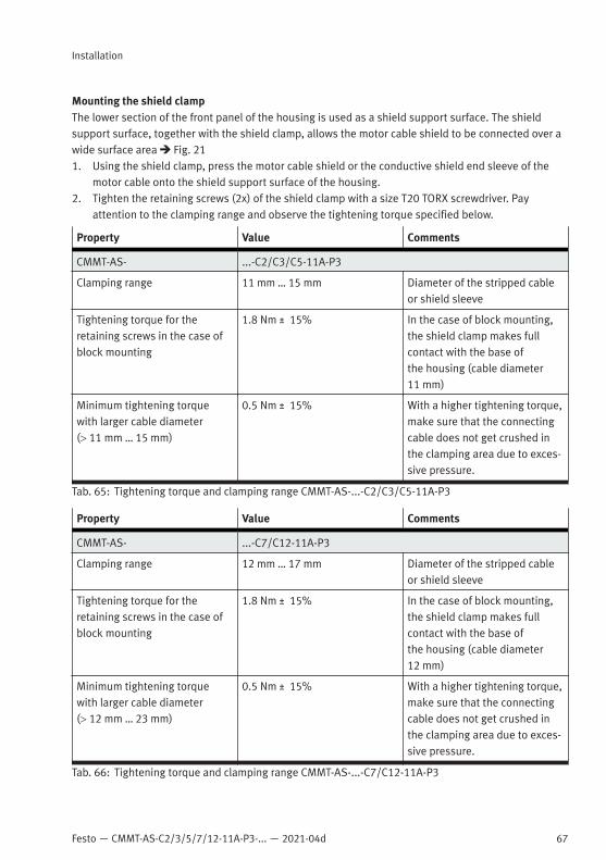
Festo — CMMT-AS-C2/3/5/7/12-11A-P3-... — 2021-04d
Installation
67
Mounting the shield clampThe lower section of the front panel of the housing is used as a shield support surface. The shieldsupport surface, together with the shield clamp, allows the motor cable shield to be connected over awide surface area è Fig. 211. Using the shield clamp, press the motor cable shield or the conductive shield end sleeve of the
motor cable onto the shield support surface of the housing.2. Tighten the retaining screws (2x) of the shield clamp with a size T20 TORX screwdriver. Pay
attention to the clamping range and observe the tightening torque specified below.
Property Value Comments
CMMT-AS- ...-C2/C3/C5-11A-P3
Clamping range 11 mm … 15 mm Diameter of the stripped cableor shield sleeve
Tightening torque for theretaining screws in the case ofblock mounting
1.8 Nm ± 15% In the case of block mounting,the shield clamp makes fullcontact with the base ofthe housing (cable diameter11 mm)
Minimum tightening torquewith larger cable diameter(> 11 mm … 15 mm)
0.5 Nm ± 15% With a higher tightening torque,make sure that the connectingcable does not get crushed inthe clamping area due to exces-sive pressure.
Tab. 65: Tightening torque and clamping range CMMT-AS-...-C2/C3/C5-11A-P3
Property Value Comments
CMMT-AS- ...-C7/C12-11A-P3
Clamping range 12 mm … 17 mm Diameter of the stripped cableor shield sleeve
Tightening torque for theretaining screws in the case ofblock mounting
1.8 Nm ± 15% In the case of block mounting,the shield clamp makes fullcontact with the base ofthe housing (cable diameter12 mm)
Minimum tightening torquewith larger cable diameter(> 12 mm … 23 mm)
0.5 Nm ± 15% With a higher tightening torque,make sure that the connectingcable does not get crushed inthe clamping area due to exces-sive pressure.
Tab. 66: Tightening torque and clamping range CMMT-AS-...-C7/C12-11A-P3
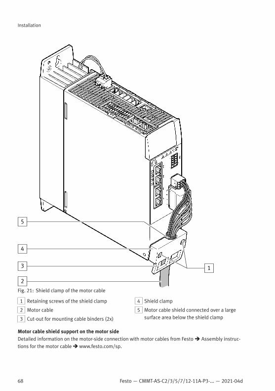
68 Festo — CMMT-AS-C2/3/5/7/12-11A-P3-... — 2021-04d
Installation
1
2
3
4
5
Fig. 21: Shield clamp of the motor cable
1 Retaining screws of the shield clamp
2 Motor cable
3 Cut-out for mounting cable binders (2x)
4 Shield clamp
5 Motor cable shield connected over a largesurface area below the shield clamp
Motor cable shield support on the motor sideDetailed information on the motor-side connection with motor cables from Festo è Assembly instruc-tions for the motor cable è www.festo.com/sp.

Festo — CMMT-AS-C2/3/5/7/12-11A-P3-... — 2021-04d
Installation
69
• Connect all shields to the PE over a wide surface area on the motor side, e.g. via the shieldconnection provided on the motor connector or the shield support surface in the motor junctionbox.
7.10 Power and logic voltage supply7.10.1 [X9A], power supply and DC link circuit connection
The connection [X9A] is located on the top of the device.The power unit of the device is supplied with electrical voltage via the connection [X9A]. In addition,the connection provides pins for DC link coupling.– Power unit of the device supplied with 3-phase mains voltage (200 V AC … 480 V AC)– Optional: DC link coupling of 3-phase devices of the same CMMT-AS seriesCross-wiring of the mains and logic voltage supply is possible with and without DC link coupling(è 7.11 Cross-wiring).
The connections for the power voltage supply and the DC link circuit are not protected against wiringerrors. The reversal of the connections results in a device defect during switch-on.With cross-wiring, observe the polarity of the DC link connection on all devices.
[X9A] Pin Function Description
6 DC+ DC link circuit positive potential
5 DC- DC link circuit negative potential
4 L3 Mains supply phase L3
3 L2 Mains supply phase L2
2 L1 Mains supply phase L1
1 PE Protective earthing
Tab. 67: Power supply and DC link circuit

70 Festo — CMMT-AS-C2/3/5/7/12-11A-P3-... — 2021-04d
Installation
Mating plug requirements
Design for single wiring connection SPC 5/ 6-ST-7.62 from Phoenix Contact or com-patible
Design for cross-wiring TSPC 5/ 6-ST-7.62 from Phoenix Contact or com-patible
Number of pins 6
Nominal current 41 A
Rated voltage (III/2) 1000 V
Pitch 7.62 mm
Strip length 15 mm
Tab. 68: Mating plug requirements
Requirements for the con-necting cable
Single device Device compound
Number of insulated wires andshielding
4 insulated wires, unshielded Without DC link coupling:4 wires, unshieldedWith DC link coupling: 6 wires,unshielded
Min. conductor cross sectionincluding wire end sleeve withplastic sleeve
0.5 mm2 1.5 mm2
Max. conductor cross sectionincluding wire end sleeve withplastic sleeve
4 mm2 4 mm2
Max. conductor cross sectionincluding wire end sleevewithout plastic sleeve
6 mm2 6 mm2
Max. length 2 m £ 0.5 m
Tab. 69: Requirements for the connecting cable
7.10.2 [X9C], logic voltage supply
The connection [X9C] is located on the top of the device. The device is supplied with logic voltage viathe connection [X9C].
WARNING
Risk of injury due to electric shock.• For the electrical power supply with extra-low voltages, use only PELV circuits that guarantee a
reinforced isolation from the mains network.• Observe IEC 60204-1/EN 60204-1.
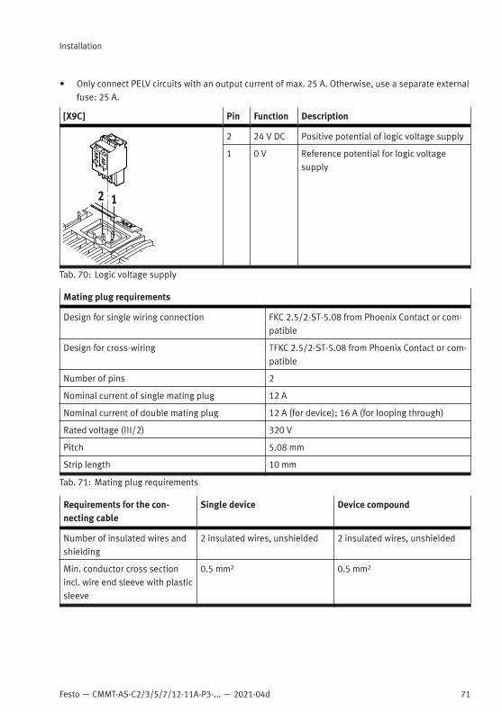
Festo — CMMT-AS-C2/3/5/7/12-11A-P3-... — 2021-04d
Installation
71
• Only connect PELV circuits with an output current of max. 25 A. Otherwise, use a separate externalfuse: 25 A.
[X9C] Pin Function Description
2 24 V DC Positive potential of logic voltage supply
1 0 V Reference potential for logic voltagesupply
Tab. 70: Logic voltage supply
Mating plug requirements
Design for single wiring connection FKC 2.5/2-ST-5.08 from Phoenix Contact or com-patible
Design for cross-wiring TFKC 2.5/2-ST-5.08 from Phoenix Contact or com-patible
Number of pins 2
Nominal current of single mating plug 12 A
Nominal current of double mating plug 12 A (for device); 16 A (for looping through)
Rated voltage (III/2) 320 V
Pitch 5.08 mm
Strip length 10 mm
Tab. 71: Mating plug requirements
Requirements for the con-necting cable
Single device Device compound
Number of insulated wires andshielding
2 insulated wires, unshielded 2 insulated wires, unshielded
Min. conductor cross sectionincl. wire end sleeve with plasticsleeve
0.5 mm2 0.5 mm2
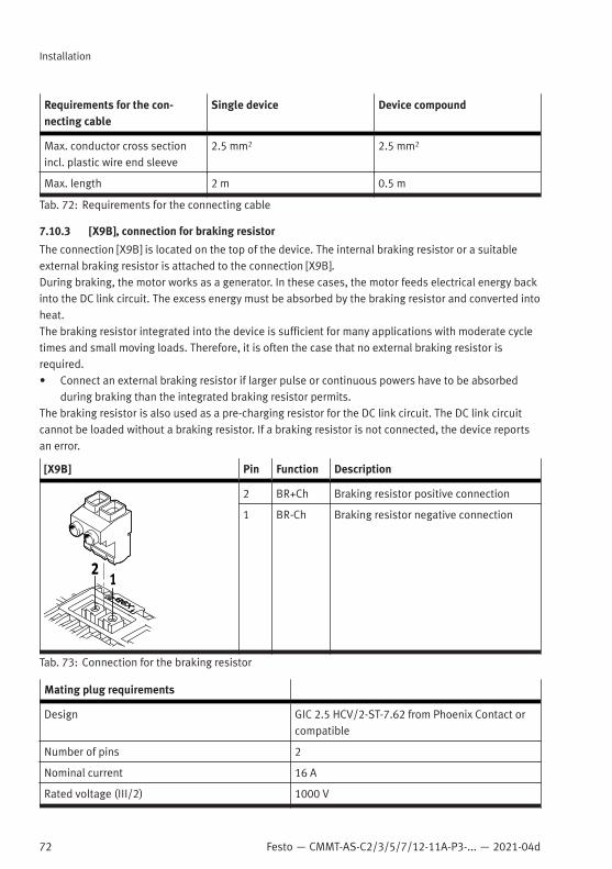
72 Festo — CMMT-AS-C2/3/5/7/12-11A-P3-... — 2021-04d
Installation
Requirements for the con-necting cable
Single device Device compound
Max. conductor cross sectionincl. plastic wire end sleeve
2.5 mm2 2.5 mm2
Max. length 2 m 0.5 m
Tab. 72: Requirements for the connecting cable
7.10.3 [X9B], connection for braking resistor
The connection [X9B] is located on the top of the device. The internal braking resistor or a suitableexternal braking resistor is attached to the connection [X9B].During braking, the motor works as a generator. In these cases, the motor feeds electrical energy backinto the DC link circuit. The excess energy must be absorbed by the braking resistor and converted intoheat.The braking resistor integrated into the device is sufficient for many applications with moderate cycletimes and small moving loads. Therefore, it is often the case that no external braking resistor isrequired.• Connect an external braking resistor if larger pulse or continuous powers have to be absorbed
during braking than the integrated braking resistor permits.The braking resistor is also used as a pre-charging resistor for the DC link circuit. The DC link circuitcannot be loaded without a braking resistor. If a braking resistor is not connected, the device reportsan error.
[X9B] Pin Function Description
2 BR+Ch Braking resistor positive connection
1 BR-Ch Braking resistor negative connection
Tab. 73: Connection for the braking resistor
Mating plug requirements
Design GIC 2.5 HCV/2-ST-7.62 from Phoenix Contact orcompatible
Number of pins 2
Nominal current 16 A
Rated voltage (III/2) 1000 V

Festo — CMMT-AS-C2/3/5/7/12-11A-P3-... — 2021-04d
Installation
73
Mating plug requirements
Pitch 7.62 mm
Strip length 8 mm
Tightening torque of the screw terminals 0.5 … 0.6 Nm1)
1) Specification of the manufacturer at the time the documentation was approved
Tab. 74: Mating plug requirements
Requirements for the connecting cables of external braking resistors
Number of insulated wires and shielding 2 wires, shielded
Min. conductor cross section incl. wire endsleeve with plastic sleeve
0.25 mm2
Max. conductor cross section incl. plastic wireend sleeve
2.5 mm2
Max. cable length 2 m
Wiring inside the control cabinet, shield connected to PE
Tab. 75: Requirements for the connecting cable
Requirements for the shield support when an external braking resistor is connected• On the device side, connect the cable shield to the earthing screw next to the upper slot of the
cooling element.Selection of suitable external braking resistorsThe connected braking resistor must fulfil the following requirements:– External braking resistors must meet the requirements of the IEC 61800-5-1 standard.– The braking resistor must be designed for operation with high pulse energy during braking.– The braking resistor must be suitable for the DC link voltage that occurs.– The resistance value of the braking resistor must be low enough for the highest braking power to be
absorbed (typically 2 … 2.5 times the nominal power of the motor).– The resistance value of the braking resistor must be within the permitted range so the brake
chopper in the device is not overloaded. Therefore, only use suitable braking resistors, i.e. thosethat are compatible with the power stage performance data of the servo drive used in terms of theirvoltage, current and pulse energy capacity.
Technical data for the integrated braking resistor and additional requirements for external brakingresistors è 10.2.3 Electrical data for braking resistor (internal/external) [X9B]Overload protection for external braking resistorsThe external braking resistor can be monitored by the firmware of the device with the help of a thermalmodel calculation. Consequently, the CMMT-AS must be parameterised as follows:– Activation of external braking resistor– Input of the following data: resistance value, continuous power and permissible pulse energyWhen the pulse energy limit is reached, the brake chopper is switched off. If the DC link voltage risesagain as a result, the power stage switches off with the message “Overload in the DC link circuit”.

74 Festo — CMMT-AS-C2/3/5/7/12-11A-P3-... — 2021-04d
Installation
7.11 Cross-wiringCross-wiring makes it possible to set up a device compound consisting of up to 10 servo drivesCMMT-AS. The different cross-wiring options are as follows:– Cross-wiring of I/O signals at the connection [X1A]– Cross-wiring of the mains and logic voltage supply without DC link coupling– Cross-wiring of the mains and logic voltage supply with DC link coupling
7.11.1 Cross-wiring of the I/O signals at the connection [X1A]
The following table shows which signals of the connection [X1A] in the device compound can beconnected directly to the same signals of neighbouring devices:
Signal name Type Short identifier Function Information
X1A.24 – RDY-C1 Normally open con-tact: ”ready foroperation message(Ready)“
Max. 10 devices,series connection ofthe contacts
X1A.23 RDY-C2
X1A.22 DOUT STA Safe torque offacknowledge
Max. 10 devices,parallel connection
X1A.21 DOUT SBA Safe brake controlacknowledge
X1A.20 – – Reserved, do notconnect
–
X1A.19 – –
X1A.18 DIN SIN4 Release brakerequest
Max. 10 devices,parallel connection
X1A.17 – GND Reference potential(ground)
Max. 10 devices,must be cross-wired
X1A.16 DOUT TRG0 Like TRG1 Use separately!
X1A.15 DOUT TRG1 Fast output for trig-gering external com-ponents
X1A.14 DIN CAP0 Like CAP1 Intended for sep-arate use, cross-wiring not usuallyadvisable, max. 10devices, parallelconnection
X1A.13 DIN CAP1 Fast input for posi-tion detection

Festo — CMMT-AS-C2/3/5/7/12-11A-P3-... — 2021-04d
Installation
75
Signal name Type Short identifier Function Information
X1A.12 #STO-A Safe torque off,channel A
Max. 10 devices,parallel connection
X1A.11 DIN #STO-B Safe torque off,channel B
X1A.10 #SBC-A Safe brake control,channel A
X1A.9 DIN #SBC-B Safe brake control,channel B
X1A.8 – – Reserved, do notconnect
–
X1A.7
X1A.6
X1A.5
X1A.4 DIN ERR-RST Functional erroracknowledgment
Max. 10 devices,parallel connection
X1A.3 DIN CTRL-EN Power stage enable
X1A.2 AIN AIN0 Differential ana-logue input
Cross-wiring is onlyadvisable if severalservo drives are toreceive the samesetpoint value viaAIN0.
X1A.1 #AIN0
Tab. 76: Information on cross-wiring of the I/O signals at the connection [X1A]
• Cross-wire the I/O signals at the connection [X1A] with the required mating plug in combinationwith double wire end sleeves.
Example for cross-wiring of I/O signalsThe following image is a schematic diagram of the cross-wiring based on the example of the signalcontact (RDY-…), a 1-channel input (here IN) and a 1-channel diagnostic output (here SOUT; digitaloutput of a safety sub-function, e.g. SBA).
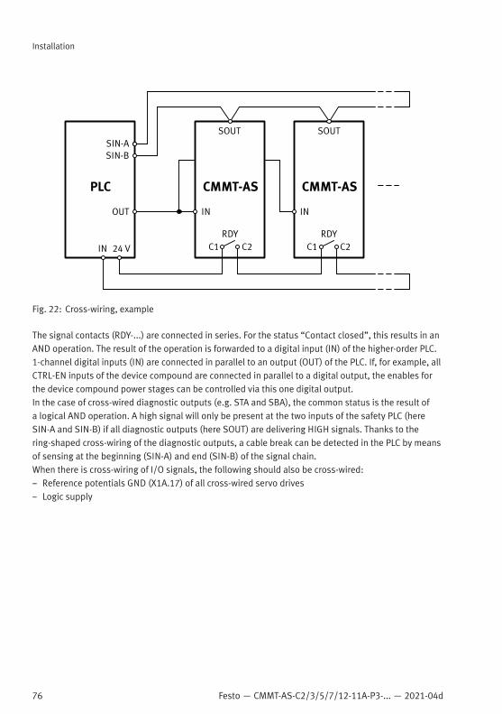
76 Festo — CMMT-AS-C2/3/5/7/12-11A-P3-... — 2021-04d
Installation
Fig. 22: Cross-wiring, example
The signal contacts (RDY-...) are connected in series. For the status “Contact closed”, this results in anAND operation. The result of the operation is forwarded to a digital input (IN) of the higher-order PLC.1-channel digital inputs (IN) are connected in parallel to an output (OUT) of the PLC. If, for example, allCTRL-EN inputs of the device compound are connected in parallel to a digital output, the enables forthe device compound power stages can be controlled via this one digital output.In the case of cross-wired diagnostic outputs (e.g. STA and SBA), the common status is the result ofa logical AND operation. A high signal will only be present at the two inputs of the safety PLC (hereSIN-A and SIN-B) if all diagnostic outputs (here SOUT) are delivering HIGH signals. Thanks to thering-shaped cross-wiring of the diagnostic outputs, a cable break can be detected in the PLC by meansof sensing at the beginning (SIN-A) and end (SIN-B) of the signal chain.When there is cross-wiring of I/O signals, the following should also be cross-wired:– Reference potentials GND (X1A.17) of all cross-wired servo drives– Logic supply
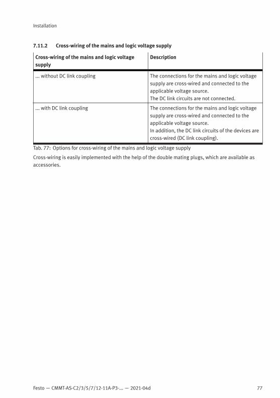
Festo — CMMT-AS-C2/3/5/7/12-11A-P3-... — 2021-04d
Installation
77
7.11.2 Cross-wiring of the mains and logic voltage supply
Cross-wiring of the mains and logic voltagesupply
Description
... without DC link coupling The connections for the mains and logic voltagesupply are cross-wired and connected to theapplicable voltage source.The DC link circuits are not connected.
... with DC link coupling The connections for the mains and logic voltagesupply are cross-wired and connected to theapplicable voltage source.In addition, the DC link circuits of the devices arecross-wired (DC link coupling).
Tab. 77: Options for cross-wiring of the mains and logic voltage supply
Cross-wiring is easily implemented with the help of the double mating plugs, which are available asaccessories.

78 Festo — CMMT-AS-C2/3/5/7/12-11A-P3-... — 2021-04d
Installation
1
2
Fig. 23: Cross-wiring CMMT-AS-...-11A-P3 (schematic diagram)
1 Double counterplug at the connection [X9A] 2 Double counterplug at the connection [X9C]
DC link couplingIf several servo drives of type CMMT-AS are used in an application, DC link coupling may be advisable.With DC link coupling, the energy recovered during braking can be provided to other servo drivesthrough the DC link circuit instead of being converted almost completely into heat via braking resis-tors. This improves the energy efficiency of the device compound by making use of the recoveredenergy.In addition, DC link coupling results in the following:

Festo — CMMT-AS-C2/3/5/7/12-11A-P3-... — 2021-04d
Installation
79
– Increased DC link circuit capacitance thanks to shared use of the DC link circuit capacitors– Increase in the braking energy to be absorbed due to shared use of the braking resistorsRules for cross-wiring the mains and logic voltage supply with and without DC link coupling
NOTICEErrors in the cross-wiring can destroy the internal electronics.• Always observe rules for cross-wiring.
– Only cross-wire devices with the same mains voltage. The devices must therefore be all 1-phasedevices or all 3-phase devices with the same mains voltage supply and DC link voltage. Cross-wiringthe mains and DC link voltage between 1-phase devices and 3-phase devices is not permitted andwill result in immediate destruction of the servo drive! The logic voltage supply can be through-con-nected.
– For 1-phase devices: connect all devices to the same mains phase.– For 3-phase devices: connect all devices to the same 3 mains phases.– Place higher-power devices closer to the mains infeed.– Insert a suitable fuse into the mains supply line for line protection and semiconductor protection.– Do not exceed the maximum number of devices in the device compound.
A device compound may consist of a maximum of 10 devices. However, the permitted number isdependent on the performance data of the devices used and the parameterised nominal currentsof the connected motors. The number is limited by the maximum permitted total current andthe maximum permitted total nominal power (dependent on the conductor cross section of thecross-wiring).
– Always connect all devices to the mains supply, even with DC link coupling. Connecting only onedevice or only one part of the device compound to the mains supply is not permitted. Such wiringcan overload and destroy devices.
Braking resistors in the device compound– A braking resistor must be connected to each device in the device compound (internal or external).– If devices with different output powers are combined, dimension the braking resistors in accordance
with the output power of the devices. This is ensured if the internal braking resistors are used.Fuse protection of a device compoundA shared external fuse is required at the mains connection of the devices. The fuse fulfils the followingfunctions:– Line protection; the rated current of the fuse must be less than or equal to the acceptable current
rating of the selected conductor cross section.– Semiconductor protection; the diode rectifiers of the devices are not protected against short circuit
currents in the DC link circuit.Recommendation:– Use automatic circuit breakers as line protection with appropriate tripping current and switching
characteristic C. For additional information è 7.3 Mains fuse.– Use class J short circuit current limiting fuses if the device is to be operated in electrical networks
with an SCCR rating > 10 kA. For additional information è 7.3 Mains fuse.
80 Festo — CMMT-AS-C2/3/5/7/12-11A-P3-... — 2021-04d
Installation
Data for operation in a device compound (CMMT-AS-...-11A-P3)A device compound may consist of a maximum of 10 devices. However, the permitted number isdependent on the performance data of the devices used.The number is limited by the value of the maximum permitted total current and the maximum per-mitted total nominal power of the device compound and depends on the conductor cross section.Choice of mains protection1. Determine total mains current of the device compound.2. Determine total current of the logic supply.3. Select the required conductor cross section for the cross-wiring.4. Select the required mains protection while also considering the conductor cross section and the
standard classification (according to UL or CE approval).Permissible maximum values è Tab. 15 Line protection requirements.Rough calculation to determine the mains currentFor 3-phase devices, the mains current can be calculated approximately as follows:Imains = 0.0024 A/W x Pnom,out
Imains: mains current [A]; Pnom,out: nominal power (electrical) at motor connection [W]Example2 servo drives each drive one motor (e.g. CMMT-AS-C5-11A-P3 for motor 1, CMMT-AS-C12-11A-P3 formotor 2).Motor 1:– Mechanical nominal power (Pnom, mech) of 2000 W– assumed degree of efficiency of the motor: 80%Pnom, out = 2000 W ¸ 0.8 = 2500 WMotor 2:– Mechanical nominal power (Pnom, mech) of 5000 W– assumed degree of efficiency of the motor: 90%Pnom,out = 5400 W ¸ 0.9 = 6000 WRequired fuseImains = 0.0024 A/W x 8500 W = 20.4 AFuse is designed for Imains: 20.4 Arms
Examples of possible device combinationsThe following table shows examples of possible device combinations, plus the fuse protectionrequired when the load on the servo drive is 100% of its nominal power:
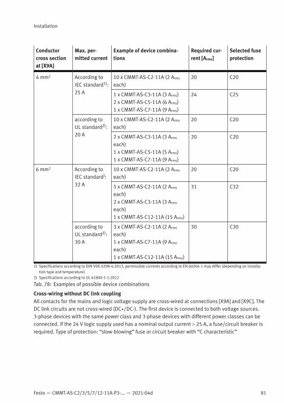
Festo — CMMT-AS-C2/3/5/7/12-11A-P3-... — 2021-04d
Installation
81
Conductorcross sectionat [X9A]
Max. per-mitted current
Example of device combina-tions
Required cur-rent [Arms]
Selected fuseprotection
4 mm2 According toIEC standard1):25 A
10 x CMMT-AS-C2-11A (2 Arms
each)20 C20
1 x CMMT-AS-C3-11A (3 Arms)2 x CMMT-AS-C5-11A (6 Arms)1 x CMMT-AS-C7-11A (9 Arms)
24 C25
according toUL standard2):20 A
10 x CMMT-AS-C2-11A (2 Arms
each)20 C20
2 x CMMT-AS-C3-11A (3 Arms
each)1 x CMMT-AS-C5-11A (5 Arms)1 x CMMT-AS-C7-11A (9 Arms)
20 C20
6 mm2 According toIEC standard):32 A
10 x CMMT-AS-C2-11A (2 Arms
each)20 C20
5 x CMMT-AS-C2-11A (2 Arms
each)2 x CMMT-AS-C3-11A (3 Arms
each)1 x CMMT-AS-C12-11A (15 Arms)
31 C32
according toUL standard2):30 A
3 x CMMT-AS-C2-11A (2 Arms
each)1 x CMMT-AS-C7-11A (9 Arms
each)1 x CMMT-AS-C12-11A (15 Arms)
30 C30
1) Specifications according to DIN VDE 0298-4:2013, permissible currents according to EN 60204-1 may differ (depending on installa-tion type and temperature)
2) Specifications according to UL 61800-5-1:2012
Tab. 78: Examples of possible device combinations
Cross-wiring without DC link couplingAll contacts for the mains and logic voltage supply are cross-wired at connections [X9A] and [X9C]. TheDC link circuits are not cross-wired (DC+/DC-). The first device is connected to both voltage sources.3-phase devices with the same power class and 3-phase devices with different power classes can beconnected. If the 24 V logic supply used has a nominal output current > 25 A, a fuse/circuit breaker isrequired. Type of protection: “slow-blowing” fuse or circuit breaker with “C characteristic”

82 Festo — CMMT-AS-C2/3/5/7/12-11A-P3-... — 2021-04d
Installation
1 2
Fig. 24: Cross-wiring without DC link coupling (CMMT-AS-...-11A-P3)
1 Main switch 2 Circuit breaker
Cross-wiring with DC link couplingAll contacts at the connections [X9A] and [X9C] are cross-wired. The first device is connected to themains voltage supply and the logic voltage supply. Mains voltage, logic voltage and DC link voltageare connected between the coupled devices. 3-phase devices with the same power class and 3-phasedevices with different power classes can be connected. If the 24 V logic supply used has a nominaloutput current > 25 A, a fuse/circuit breaker is required. Type of protection: “slow-blowing” fuse orcircuit breaker with “C characteristic”

Festo — CMMT-AS-C2/3/5/7/12-11A-P3-... — 2021-04d
Malfunctions
83
1 2
Fig. 25: Cross-wiring with DC link coupling (CMMT-AS-...-11A-P3)
1 Main switch 2 Circuit breaker
8 Malfunctions8.1 Diagnostics via LEDOn the front and top of the device, there are some LEDs for indicating status information. The numberof LEDs depends on the product design. Up to 11 LEDs are located on the front of the device. Up to 4LEDs are located on the top of the device at the connections [X19], XF1 IN and XF2 OUT.The following image shows an example of the LEDs on the front of product variant CMMT-AS-...-EC. Thelabelling and function of the Run LED and Error LED vary according to the product variant.

84 Festo — CMMT-AS-C2/3/5/7/12-11A-P3-... — 2021-04d
Malfunctions
1
2
3
4
5
6
7
8
Fig. 26: LEDs on the front
1 Device status (4 LEDs)
2 Run (example CMMT-AS-...-EC)
3 Error (example CMMT-AS-...-EC)
4 Ethernet interface activated [X18]
5 Communication activity [X18]
6 Sync interface activated [X10]
7 Encoder status, encoder interface [X3]
8 Encoder status, encoder interface [X2]
8.1.1 Device status displays
LED Designation Brief description
Status LED Indicates the general device status
Power LED Indicates the status of the power supply
Safety LED Indicates the status of the safety equipment
Application status LED Indicates the identification sequence and isreserved for future extensions
Tab. 79: Device status LEDs (status, power, safety and application status LEDs)
LED testAfter the device is switched on, it runs through an initialisation phase. When the initialisation phase iscomplete, the device performs an LED test. During the LED test, the 4 device status LEDs are activatedsimultaneously. The 4 device status LEDs light up yellow for approx. 300 ms.
Status LED, display of the device status
LED Meaning
Flashes red
An error is present.
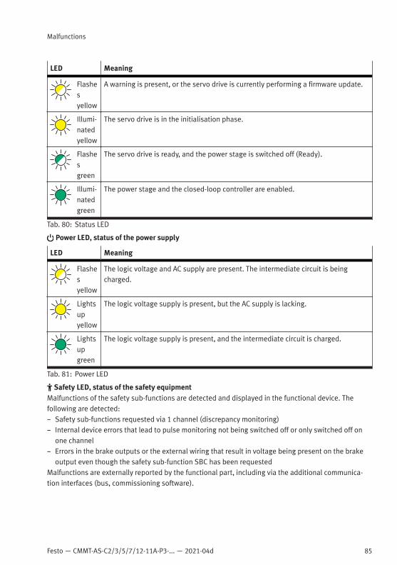
Festo — CMMT-AS-C2/3/5/7/12-11A-P3-... — 2021-04d
Malfunctions
85
LED Meaning
Flashesyellow
A warning is present, or the servo drive is currently performing a firmware update.
Illumi-natedyellow
The servo drive is in the initialisation phase.
Flashesgreen
The servo drive is ready, and the power stage is switched off (Ready).
Illumi-natedgreen
The power stage and the closed-loop controller are enabled.
Tab. 80: Status LED
Power LED, status of the power supply
LED Meaning
Flashesyellow
The logic voltage and AC supply are present. The intermediate circuit is beingcharged.
Lightsupyellow
The logic voltage supply is present, but the AC supply is lacking.
Lightsupgreen
The logic voltage supply is present, and the intermediate circuit is charged.
Tab. 81: Power LED
Safety LED, status of the safety equipmentMalfunctions of the safety sub-functions are detected and displayed in the functional device. Thefollowing are detected:– Safety sub-functions requested via 1 channel (discrepancy monitoring)– Internal device errors that lead to pulse monitoring not being switched off or only switched off on
one channel– Errors in the brake outputs or the external wiring that result in voltage being present on the brake
output even though the safety sub-function SBC has been requestedMalfunctions are externally reported by the functional part, including via the additional communica-tion interfaces (bus, commissioning software).

86 Festo — CMMT-AS-C2/3/5/7/12-11A-P3-... — 2021-04d
Malfunctions
LED Meaning
Flashes red
Error in the safety part or a safety condition has been violated.
Flashesyellow
The safety sub-function has been requested but is not yet active.
Illumi-natedyellow
The safety sub-function has been requested and is active.
Flashesgreen
Power stage, brake outputs and safety diagnostic outputs are blocked (safetyparameterisation is running).
Illumi-natedgreen
Ready, no safety sub-function has been requested.
Tab. 82: Safety LED
Application status
LED Meaning
Flashesalter-natelybetweenred,yellowandgreen
Identification sequence active (for optical identification of the device in a network),which can be activated via the parameterisation software

Festo — CMMT-AS-C2/3/5/7/12-11A-P3-... — 2021-04d
Malfunctions
87
LED Meaning
Flashesyellow
Reserved for future extensions
Lightsupyellow
Flashesgreen
Lightsupgreen
Tab. 83: Application status LED
Special function of the start program (bootloader) during firmware updatesWhen the bootloader starts the update procedure, the status LED flashes yellow at half-secondintervals. The power LED, safety LED and application status LED remain dark.If the bootloader is waiting for inputs, e.g. via the CDSB, the status LED lights up yellow. The powerLED, safety LED and application status LED remain dark.If an error occurs during a firmware update, the status LED flashes red at one-second intervals. Thefrequency of flashing corresponds to the error number specified in the following table. After flashing,there is a pause of 3 s. Then the procedure repeats.
Error number Description
1 The start program has detected a CRC error in the firmware after switching on.
2 The start program has detected a CRC error in the start program after switching on.
3 The start program is supposed to update the firmware but has detected an error inthe system update file.
4 The start program is supposed to update itself and the firmware but has detected adefective start program in the system update file.
5 The start program cannot access the file system or the system update file, or thesystem update file is defective.
Tab. 84: Error messages of the start program (bootloader)
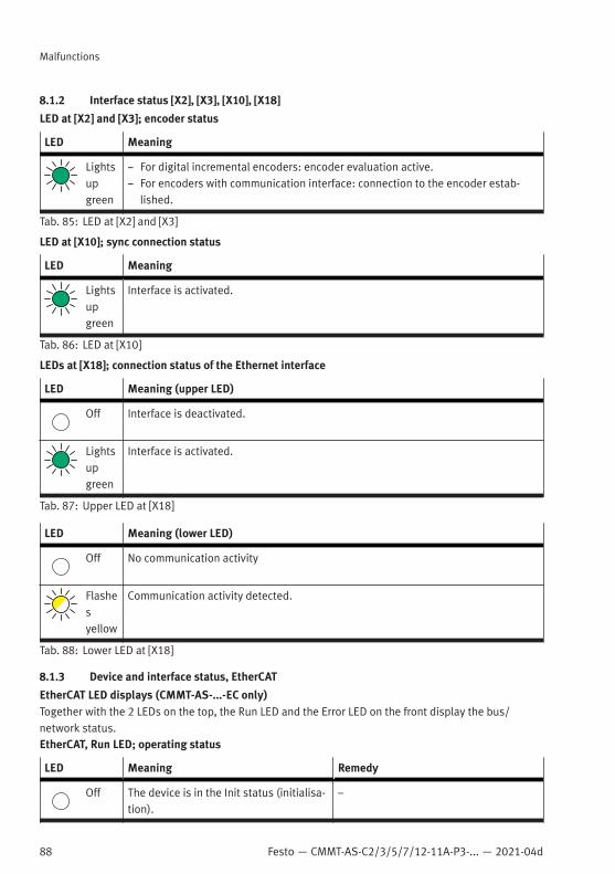
88 Festo — CMMT-AS-C2/3/5/7/12-11A-P3-... — 2021-04d
Malfunctions
8.1.2 Interface status [X2], [X3], [X10], [X18]
LED at [X2] and [X3]; encoder status
LED Meaning
Lightsupgreen
– For digital incremental encoders: encoder evaluation active.– For encoders with communication interface: connection to the encoder estab-
lished.
Tab. 85: LED at [X2] and [X3]
LED at [X10]; sync connection status
LED Meaning
Lightsupgreen
Interface is activated.
Tab. 86: LED at [X10]
LEDs at [X18]; connection status of the Ethernet interface
LED Meaning (upper LED)
Off Interface is deactivated.
Lightsupgreen
Interface is activated.
Tab. 87: Upper LED at [X18]
LED Meaning (lower LED)
Off No communication activity
Flashesyellow
Communication activity detected.
Tab. 88: Lower LED at [X18]
8.1.3 Device and interface status, EtherCAT
EtherCAT LED displays (CMMT-AS-...-EC only)Together with the 2 LEDs on the top, the Run LED and the Error LED on the front display the bus/network status.EtherCAT, Run LED; operating status
LED Meaning Remedy
Off The device is in the Init status (initialisa-tion).
–
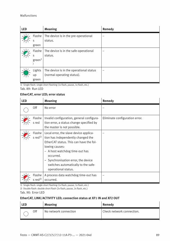
Festo — CMMT-AS-C2/3/5/7/12-11A-P3-... — 2021-04d
Malfunctions
89
LED Meaning Remedy
Flashesgreen
The device is in the pre-operationalstatus.
–
Flashesgreen1
)
The device is in the safe-operationalstatus.
–
Lightsupgreen
The device is in the operational status(normal operating status).
–
1) Single flash: single short flashing (1x flash, pause, 1x flash, etc.)
Tab. 89: Run LED
EtherCAT, error LED; error status
LED Meaning Remedy
Off No error –
Flashes red
Invalid configuration, general configura-tion error, a status change specified bythe master is not possible.
Eliminate configuration error.
Flashes red1)
Local error, the slave device applica-tion has independently changed theEtherCAT status. This can have the fol-lowing causes:– A host watchdog time-out has
occurred.– Synchronisation error, the device
switches automatically to the safe-operational status.
–
Flashes red2)
A process data watchdog time-out hasoccurred.
–
1) Single flash: single short flashing (1x flash, pause, 1x flash, etc.)2) Double flash: double short flash (2x flash, pause, 2x flash, etc.)
Tab. 90: Error LED
EtherCAT, LINK/ACTIVITY LED; connection status at XF1 IN and XF2 OUT
LED Meaning Remedy
Off No network connection Check network connection.
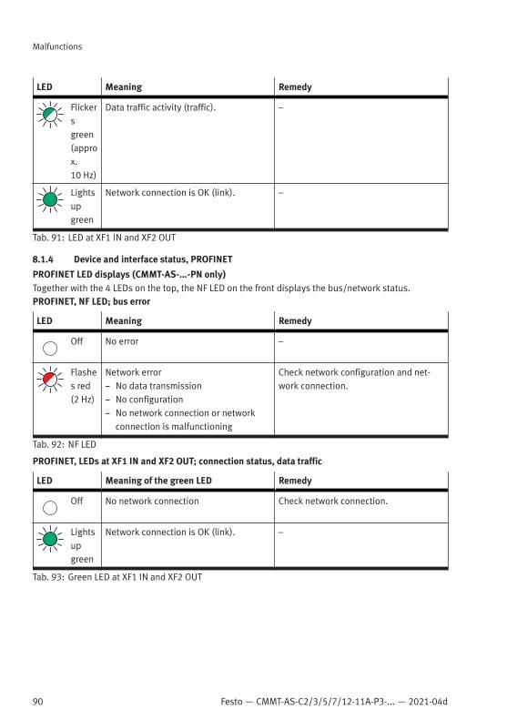
90 Festo — CMMT-AS-C2/3/5/7/12-11A-P3-... — 2021-04d
Malfunctions
LED Meaning Remedy
Flickersgreen(approx.10 Hz)
Data traffic activity (traffic). –
Lightsupgreen
Network connection is OK (link). –
Tab. 91: LED at XF1 IN and XF2 OUT
8.1.4 Device and interface status, PROFINET
PROFINET LED displays (CMMT-AS-...-PN only)Together with the 4 LEDs on the top, the NF LED on the front displays the bus/network status.PROFINET, NF LED; bus error
LED Meaning Remedy
Off No error –
Flashes red(2 Hz)
Network error– No data transmission– No configuration– No network connection or network
connection is malfunctioning
Check network configuration and net-work connection.
Tab. 92: NF LED
PROFINET, LEDs at XF1 IN and XF2 OUT; connection status, data traffic
LED Meaning of the green LED Remedy
Off No network connection Check network connection.
Lightsupgreen
Network connection is OK (link). –
Tab. 93: Green LED at XF1 IN and XF2 OUT
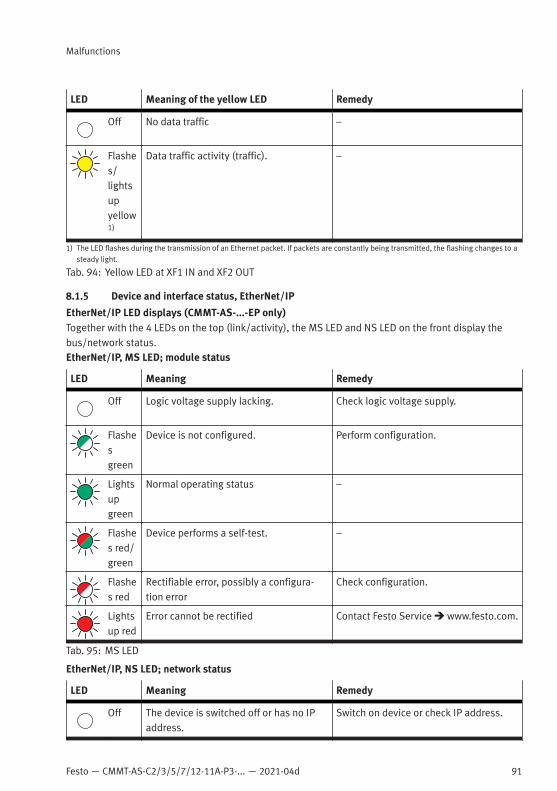
Festo — CMMT-AS-C2/3/5/7/12-11A-P3-... — 2021-04d
Malfunctions
91
LED Meaning of the yellow LED Remedy
Off No data traffic –
Flashes/lightsupyellow1)
Data traffic activity (traffic). –
1) The LED flashes during the transmission of an Ethernet packet. If packets are constantly being transmitted, the flashing changes to asteady light.
Tab. 94: Yellow LED at XF1 IN and XF2 OUT
8.1.5 Device and interface status, EtherNet/IP
EtherNet/IP LED displays (CMMT-AS-...-EP only)Together with the 4 LEDs on the top (link/activity), the MS LED and NS LED on the front display thebus/network status.EtherNet/IP, MS LED; module status
LED Meaning Remedy
Off Logic voltage supply lacking. Check logic voltage supply.
Flashesgreen
Device is not configured. Perform configuration.
Lightsupgreen
Normal operating status –
Flashes red/green
Device performs a self-test. –
Flashes red
Rectifiable error, possibly a configura-tion error
Check configuration.
Lightsup red
Error cannot be rectified Contact Festo Service è www.festo.com.
Tab. 95: MS LED
EtherNet/IP, NS LED; network status
LED Meaning Remedy
Off The device is switched off or has no IPaddress.
Switch on device or check IP address.

92 Festo — CMMT-AS-C2/3/5/7/12-11A-P3-... — 2021-04d
Disassembly
LED Meaning Remedy
Flashesgreen
The device has an IP address but no CIPconnection.It may be that the device is not assignedto a master/scanner.
Eliminate configuration error.
Lightsupgreen
Normal operating status.The device is online and has a CIP con-nection.
–
Flashes red/green
Device performs a self-test. –
Flashes red
One or more I/O connections are in thetime-out status.
Check the physical connection to themaster/scanner.
Lightsup red
The IP address of the device has alreadybeen assigned.
Check and correct IP addresses in thenetwork.
Tab. 96: NS LED
EtherNet/IP, LED at XF1 IN and XF2 OUT; connection status, data traffic
LED Meaning of the green LED Remedy
Off No network connection Check network connection.
Lightsupgreen
Network connection is OK (link). –
Tab. 97: Green LED at XF1 IN and XF2 OUT
LED Meaning of the yellow LED Remedy
Off No data traffic –
Flickersyellow
Data traffic activity. –
Tab. 98: Yellow LED at XF1 IN and XF2 OUT
9 DisassemblyDisassemble in reverse order of installation.Before disassembly1. Switch off the power supply at the main switch.2. Secure the system against accidental reactivation.3. Wait at least 5 minutes until the intermediate circuit has discharged.

Festo — CMMT-AS-C2/3/5/7/12-11A-P3-... — 2021-04d
Technical data
93
4. Let the device cool down to room temperature.5. Before touching the power connections [X6A], [X9A], [X9B], check to ensure they are free of
voltage.6. Disconnect all electrical cables.To dismount the device• Loosen retaining screws (2x) and remove the device from the mounting surface.
10 Technical data10.1 General technical data
Product conformity
CE marking (declaration of con-formity è www.festo.com/sp)
in accordance with EU EMC Directive1)
in accordance with EU Machinery Directivein accordance with EU RoHS Directive
1) The device is intended for use in an industrial environment and with appropriate measures in commercial, residential and mixedareas.
Tab. 99: Product conformity
General technical data
Type ID code CMMT-AS
Type of mounting Mounting plate, attached with screws
Mounting position vertical, mounted on closed surface, free convection with unhin-dered air flow from bottom to top
Dimensions (H*W*D) è 6 Assembly
Product weight [kg] CMMT-AS-C2-11A-P3: 2.1CMMT-AS-C3-11A-P3: 2.1CMMT-AS-C5-11A-P3: 2.2CMMT-AS-C7-11A-P3: 4.1CMMT-AS-C12-11A-P3: 4.1
Displays – Device status display: 4 LEDs– Bus-specific status:– CMMT-AS-...-EC: 2 LEDs– CMMT-AS-...-EP: 2 LEDs– CMMT-AS-...-PN: 1 LED
– Interface status [X19] (IN, OUT):– CMMT-AS-...-EC: 2 LEDs– CMMT-AS-...-EP: 4 LEDs– CMMT-AS-...-PN: 4 LEDs
– Interface status [X2], [X3], [X10], [X18]: 4 LEDs– Interface activity [X18]: 1 LED
Control elements Optional: operator unit CDSB

94 Festo — CMMT-AS-C2/3/5/7/12-11A-P3-... — 2021-04d
Technical data
General technical data
Parameterisation interface – [X18], Ethernet; parameterisation and configuration via com-missioning software (è è www.festo.com/sp)
– [X19] IN/OUT, RT Ethernet; parameterisation and configurationvia bus protocol
– [X5], configuration/data transfer via the removable operatorunit
RT Ethernet protocol CMMT-AS-...-EC: EtherCATCMMT-AS-...-EP: EtherNet/IPCMMT-AS-...-PN: PROFINET
Tab. 100: General technical data
Ambient conditions, transport
Transport temperature [°C] −25 … +70
Relative humidity [%] 5 … 95 (non-condensing)
Max. transportationduration
[d] 30
Permissible altitude [m] 12000 (above sea level) for 12 h
Vibration resistance Vibration test and free fall in packaging in accordance withEN 61800-2
Tab. 101: Ambient conditions, transport
Ambient conditions, storage
Storage temperature [°C] −25 … +55
Relative humidity [%] 5 … 95 (non-condensing)
Permissible altitude [m] 3000 (above sea level)
Tab. 102: Ambient conditions, storage
Ambient conditions, operation
Ambient temperatureat nominal power
[°C] 0 … +40
Ambient temperaturewith derating(–3%/C at40°C … 50°C)
[°C] 0 … +50
Cooling by ambient air in the control cabinet; from CMMT-AS-C5-11A-P3also via forced ventilation through an integrated fan

Festo — CMMT-AS-C2/3/5/7/12-11A-P3-... — 2021-04d
Technical data
95
Ambient conditions, operation
Temperature moni-toring
Monitoring of:– Cooling element (power module)– Air in the deviceSwitch-off if temperature is too high or too low
Relative humidity [%] 5 … 90 (non-condensing), no corrosive media permitted near thedevice
Permissible setup alti-tude above sea level atnominal power
[m] 0 … 1000
Permissible setup alti-tude above sea levelwith derating(–10 %/1000 m at1000 m … 2000 m)
[m] 0 … 2000Operation above 2000 m is not permitted!
Degree of protectionin accordance withEN 60529
IP20 (with attached mating plug X9A and with intendedmounting on closed backwall, otherwise IP10)
Requirements forinstallation space
Use in a control cabinet with at least IP54, design as “closedelectrical operating area” in accordance with IEC 61800-5-1,Chap. 3.5
Protection class I
Overvoltage category III
Pollution degree 2 (or better)
Vibration resistance inaccordance with
IEC 61800-5-1 and EN 61800-2
Shock resistance inaccordance with
EN 61800-2
Tab. 103: Ambient conditions, operation

96 Festo — CMMT-AS-C2/3/5/7/12-11A-P3-... — 2021-04d
Technical data
Service life
Service life of thedevice at rated loadin S1 operation1) and40 °C ambient temper-ature
[h] 25000
Service life of thedevice at <50% ratedload in S1 operation1)
and 40 °C ambient tem-perature
[h] 50000
1) Continuous operation under constant load
Tab. 104: Service life
Materials
CMMT-AS C2/C3/C5-11A-P3 C7/C12-11A-P3
Housing Plastic Plastic, aluminium sheet
Cooling profile Die-cast aluminium
Tab. 105: Materials
10.2 Technical data, electrical10.2.1 Load voltage supply [X9A]
Electrical data, load voltage supply [X9A]
Number of phases 3
Voltage range [V AC] 200 – 10 % … 480 + 10 %
Voltage range withderating(–1.5 %/10 V AC)
[V AC] 400 … 530
Nominal operatingvoltage
[V AC] 400
System voltage inaccordance withIEC 61800-5-1
[V AC] 300
Mains frequency [Hz] 48 … 62
Network connec-tion/allowed mainstypes of systemearthing1)
L1 è L2 è L3: TT, TN, IT
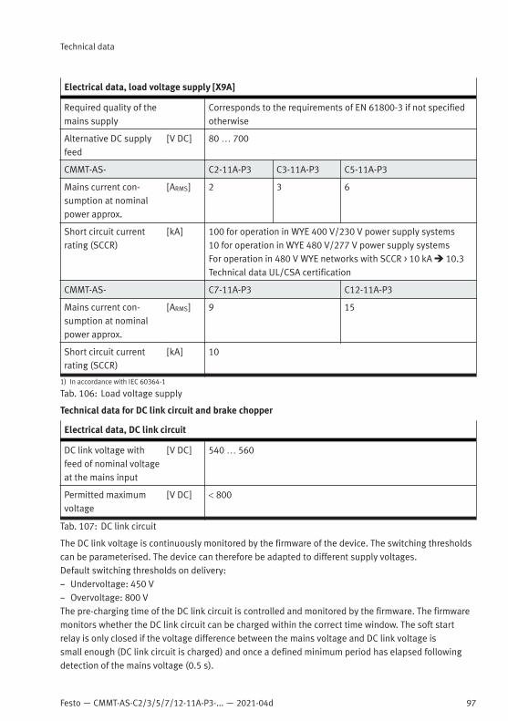
Festo — CMMT-AS-C2/3/5/7/12-11A-P3-... — 2021-04d
Technical data
97
Electrical data, load voltage supply [X9A]
Required quality of themains supply
Corresponds to the requirements of EN 61800-3 if not specifiedotherwise
Alternative DC supplyfeed
[V DC] 80 … 700
CMMT-AS- C2-11A-P3 C3-11A-P3 C5-11A-P3
Mains current con-sumption at nominalpower approx.
[ARMS] 2 3 6
Short circuit currentrating (SCCR)
[kA] 100 for operation in WYE 400 V/230 V power supply systems10 for operation in WYE 480 V/277 V power supply systemsFor operation in 480 V WYE networks with SCCR > 10 kA è 10.3Technical data UL/CSA certification
CMMT-AS- C7-11A-P3 C12-11A-P3
Mains current con-sumption at nominalpower approx.
[ARMS] 9 15
Short circuit currentrating (SCCR)
[kA] 10
1) In accordance with IEC 60364-1
Tab. 106: Load voltage supply
Technical data for DC link circuit and brake chopper
Electrical data, DC link circuit
DC link voltage withfeed of nominal voltageat the mains input
[V DC] 540 … 560
Permitted maximumvoltage
[V DC] < 800
Tab. 107: DC link circuit
The DC link voltage is continuously monitored by the firmware of the device. The switching thresholdscan be parameterised. The device can therefore be adapted to different supply voltages.Default switching thresholds on delivery:– Undervoltage: 450 V– Overvoltage: 800 VThe pre-charging time of the DC link circuit is controlled and monitored by the firmware. The firmwaremonitors whether the DC link circuit can be charged within the correct time window. The soft startrelay is only closed if the voltage difference between the mains voltage and DC link voltage issmall enough (DC link circuit is charged) and once a defined minimum period has elapsed followingdetection of the mains voltage (0.5 s).
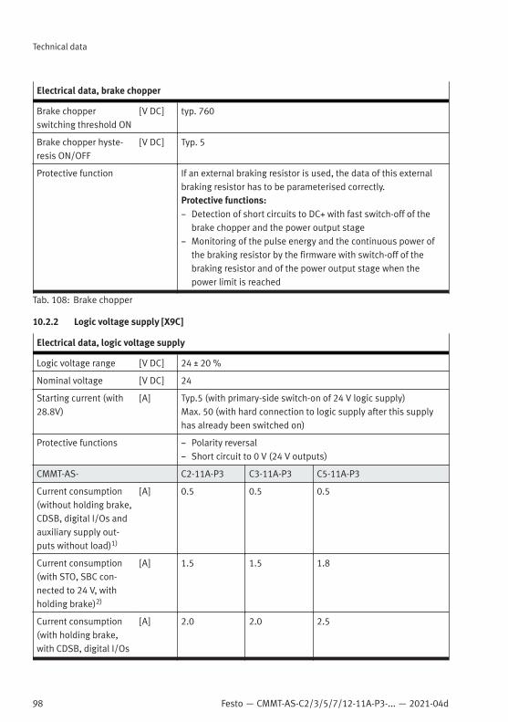
98 Festo — CMMT-AS-C2/3/5/7/12-11A-P3-... — 2021-04d
Technical data
Electrical data, brake chopper
Brake chopperswitching threshold ON
[V DC] typ. 760
Brake chopper hyste-resis ON/OFF
[V DC] Typ. 5
Protective function If an external braking resistor is used, the data of this externalbraking resistor has to be parameterised correctly.Protective functions:– Detection of short circuits to DC+ with fast switch-off of the
brake chopper and the power output stage– Monitoring of the pulse energy and the continuous power of
the braking resistor by the firmware with switch-off of thebraking resistor and of the power output stage when thepower limit is reached
Tab. 108: Brake chopper
10.2.2 Logic voltage supply [X9C]
Electrical data, logic voltage supply
Logic voltage range [V DC] 24 ± 20 %
Nominal voltage [V DC] 24
Starting current (with28.8V)
[A] Typ.5 (with primary-side switch-on of 24 V logic supply)Max. 50 (with hard connection to logic supply after this supplyhas already been switched on)
Protective functions – Polarity reversal– Short circuit to 0 V (24 V outputs)
CMMT-AS- C2-11A-P3 C3-11A-P3 C5-11A-P3
Current consumption(without holding brake,CDSB, digital I/Os andauxiliary supply out-puts without load)1)
[A] 0.5 0.5 0.5
Current consumption(with STO, SBC con-nected to 24 V, withholding brake)2)
[A] 1.5 1.5 1.8
Current consumption(with holding brake,with CDSB, digital I/Os
[A] 2.0 2.0 2.5

Festo — CMMT-AS-C2/3/5/7/12-11A-P3-... — 2021-04d
Technical data
99
Electrical data, logic voltage supply
and auxiliary supplyoutputs with load andwith fan, if present)2)
CMMT-AS- C7-11A-P3 C12-11A-P3
Current consumption(without holding brake,CDSB, digital I/Os andauxiliary supply out-puts without load)3)
[A] 0.5 0.5
Current consumption(with STO, SBC con-nected to 24 V, withholding brake)4)
[A] 2.0 2.0
Current consumption(with holding brake,with CDSB, digital I/Osand auxiliary supplyoutputs with load andwith fan)2)
[A] 2.5 2.5
1) Includes current for the STO inputs2) Includes current consumption for power stage ON and for STO inputs3) Includes current for the STO inputs4) Includes current consumption for power stage ON and for STO inputs
Tab. 109: Logic voltage supply
10.2.3 Electrical data for braking resistor (internal/external) [X9B]
Integrated braking resistor [X9B]
CMMT-AS- C2-11A-P3 C3-11A-P3 C5-11A-P3
Resistance [Ω] 130 130 130
Pulse power [W] 5000 5000 5000
Pulse energy [Ws] 850 850 850
Continuous power(specificationaccording to IEC) at70 °C ambient temper-ature1)2)
[W] 48 48 58
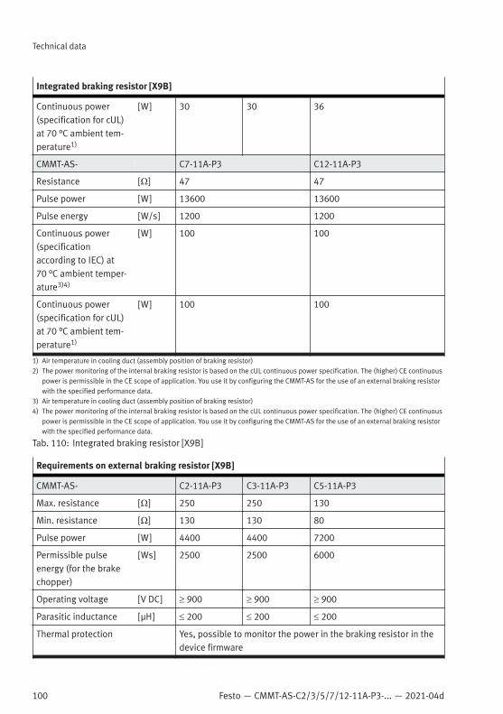
100 Festo — CMMT-AS-C2/3/5/7/12-11A-P3-... — 2021-04d
Technical data
Integrated braking resistor [X9B]
Continuous power(specification for cUL)at 70 °C ambient tem-perature1)
[W] 30 30 36
CMMT-AS- C7-11A-P3 C12-11A-P3
Resistance [Ω] 47 47
Pulse power [W] 13600 13600
Pulse energy [W/s] 1200 1200
Continuous power(specificationaccording to IEC) at70 °C ambient temper-ature3)4)
[W] 100 100
Continuous power(specification for cUL)at 70 °C ambient tem-perature1)
[W] 100 100
1) Air temperature in cooling duct (assembly position of braking resistor)2) The power monitoring of the internal braking resistor is based on the cUL continuous power specification. The (higher) CE continuous
power is permissible in the CE scope of application. You use it by configuring the CMMT-AS for the use of an external braking resistorwith the specified performance data.
3) Air temperature in cooling duct (assembly position of braking resistor)4) The power monitoring of the internal braking resistor is based on the cUL continuous power specification. The (higher) CE continuous
power is permissible in the CE scope of application. You use it by configuring the CMMT-AS for the use of an external braking resistorwith the specified performance data.
Tab. 110: Integrated braking resistor [X9B]
Requirements on external braking resistor [X9B]
CMMT-AS- C2-11A-P3 C3-11A-P3 C5-11A-P3
Max. resistance [Ω] 250 250 130
Min. resistance [Ω] 130 130 80
Pulse power [W] 4400 4400 7200
Permissible pulseenergy (for the brakechopper)
[Ws] 2500 2500 6000
Operating voltage [V DC] ³ 900 ³ 900 ³ 900
Parasitic inductance [µH] £ 200 £ 200 £ 200
Thermal protection Yes, possible to monitor the power in the braking resistor in thedevice firmware
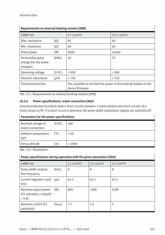
Festo — CMMT-AS-C2/3/5/7/12-11A-P3-... — 2021-04d
Technical data
101
Requirements on external braking resistor [X9B]
CMMT-AS- C7-11A-P3 C12-11A-P3
Max. resistance [Ω] 85 60
Min. resistance [Ω] 60 40
Pulse power [W] 9600 14440
Permissible pulseenergy (for the brakechopper)
[kWs] 10 15
Operating voltage [V DC] ³ 900 ³ 900
Parasitic inductance [µH] £ 150 £ 150
Thermal protection Yes, possible to monitor the power in the braking resistor in thedevice firmware
Tab. 111: Requirements on external braking resistor [X9B]
10.2.4 Power specifications, motor connection [X6A]
Internal protective functions detect short circuits between 2 motor phases and short circuits of amotor phase to PE. If a short circuit is detected, the pulse-width modulation signals are switched off.
Parameters for the power specifications
Nominal voltage ofmains connection
[V AC] 400
Ambient temperature(air)
[°C] £ 40
Setup altitude [m] £ 1000
Tab. 112: Parameters
Power specifications during operation with the given parameters [X6A]
CMMT-AS- C2-11A-P3 C3-11A-P3 C5-11A-P3
Pulse-width modula-tion frequency
[kHz] 8 8 8
Current-regulator cycletime
[µs] 62.5 62.5 62.5
Nominal output power(S1 operation; cos(phi)> 0.8)
[W] 800 1200 2500
Nominal current (S1operation)
[ARMS] 1.7 2.5 5

102 Festo — CMMT-AS-C2/3/5/7/12-11A-P3-... — 2021-04d
Technical data
Power specifications during operation with the given parameters [X6A]
Max. output power(S2 operation; cos(phi)> 0.8)
[W] 2400 3600 7500
Maximum current [ARMS] 5.1 7.5 15
CMMT-AS- C7-11A-P3 C12-11A-P3
Pulse-width modula-tion frequency
[kHz] 8 8
Current-regulator cycletime
[µs] 62.5 62.5
Nominal output power(S1 operation; cos(phi)> 0.8)
[W] 4000 6000
Nominal current (S1operation)
[ARMS] 7 12
Max. output power(S2 operation; cos(phi)> 0.8)
[W] 10 000 17 000
Maximum current [ARMS] 21 36
CMMT-AS- ...-11A-P3
Output voltage range [VRMS] 3 x 0 … input
Output voltage withfeed of nominal voltageand nominal power
[VRMS] 380
Output frequency [Hz] 0 … 599
Duration for maximumcurrent(fs > 5 Hz)
[s] 2
Duration for maximumcurrent at standstill(fs £ 5 Hz); minimumcycle time 1 s!
[s] 0.1
Tab. 113: Power specifications, motor connection [X6A]
If the parameters do not conform to those stated, the power specifications listed above will not beachieved. In this case, the following deratings apply. The deratings refer simultaneously to nominaloutput power, max. output power, nominal current and maximum current.
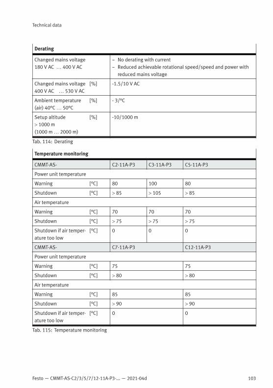
Festo — CMMT-AS-C2/3/5/7/12-11A-P3-... — 2021-04d
Technical data
103
Derating
Changed mains voltage180 V AC … 400 V AC
– No derating with current– Reduced achievable rotational speed/speed and power with
reduced mains voltage
Changed mains voltage400 V AC … 530 V AC
[%] -1.5/10 V AC
Ambient temperature(air) 40°C … 50°C
[%] - 3/°C
Setup altitude> 1000 m(1000 m … 2000 m)
[%] -10/1000 m
Tab. 114: Derating
Temperature monitoring
CMMT-AS- C2-11A-P3 C3-11A-P3 C5-11A-P3
Power unit temperature
Warning [°C] 80 100 80
Shutdown [°C] > 85 > 105 > 85
Air temperature
Warning [°C] 70 70 70
Shutdown [°C] > 75 > 75 > 75
Shutdown if air temper-ature too low
[°C] 0 0 0
CMMT-AS- C7-11A-P3 C12-11A-P3
Power unit temperature
Warning [°C] 75 75
Shutdown [°C] > 80 > 80
Air temperature
Warning [°C] 85 85
Shutdown [°C] > 90 > 90
Shutdown if air temper-ature too low
[°C] 0 0
Tab. 115: Temperature monitoring

104 Festo — CMMT-AS-C2/3/5/7/12-11A-P3-... — 2021-04d
Technical data
10.2.5 Motor auxiliary connection [X6B]
Motor temperature monitoring [X6B]
Analogue sensors Analogue temperature sensors with gain and offset– KTY 81 … 84 (silicon temperature sensors)– PTC (PTC resistor, positive temperature coefficient)– NTC (NTC resistor, negative temperature coefficient)– Pt1000 (platinum measuring resistor)
Digital sensors – N/C contact– N/O contact
Tab. 116: Motor temperature monitoring [X6B]
Output of holding brake [X6B]
CMMT-AS- C2-11A-P3 C3-11A-P3 C5-11A-P3
Max. continuousoutput current
[A] 1 1 1.3
Max. voltage drop from+ 24 V input at con-nection [X9A] to brakeoutput at [X6B]
[V DC] 0.8 0.8 1
Max. permissibleinductive load
[H] < 5 < 5 < 5
CMMT-AS- C7-11A-P3 C12-11A-P3
Max. continuousoutput current
1.5 1.5
Max. voltage drop from+ 24 V input at con-nection [X9A] to brakeoutput at [X6B]
1.7 1.7
Max. permissibleinductive load
< 5 < 5
CMMT-AS- ...-11A-P3
Design High-side switch1)

Festo — CMMT-AS-C2/3/5/7/12-11A-P3-... — 2021-04d
Technical data
105
Output of holding brake [X6B]
Protective functions – Short circuit protected 0 V/FE– overvoltage-proof up to 60 V2)
– Thermal overload protection
Error detection Voltage at output despite brake having shut downDiagnostics possible via:– Diagnostic output for safety sub-function SBC– Error message on device
1) The test pulses of the associated control input #SBC-A are mapped to the output subject to a switching delay.2) Brake output also shuts down in the event of a fault if there is an overvoltage on the logic supply.
Tab. 117: Output of holding brake [X6B], 3-phase devices
10.2.6 Encoder interfaces [X2], [X3]
EnDat 2.1 encoder at [X2]
Parameterisable no. ofencoder pulses
1 … 16777216 position values/revolution (24 bit)
Angle resolution/inter-polation
None; digital angle signal from encoder
Clock signal [MHz] RS422/485; max. 2
Data channel [MHz] RS422/485; max. 2
Input impedance data [Ω] RS422/485; 120
Output supply [mA] Max. 250 (at 5.00 V … 5.50 V)
Support: mechanicalmultiturn encoder
Yes, up to 4096 revolutions
Support: battery-buf-fered multiturnencoder
No
Support: encoderparameter memory
Yes, storing of controller parameters in encoder
Support: encoder errormessages
Yes, supported
Encoder communica-tion failure
Up to 2 corrupted/failed encoder messages tolerated. After thisan error message will be generated.
Tab. 118: EnDat 2.1 encoder at [X2]
EnDat 2.2 encoder at [X2]
Parameterisable no. ofencoder pulses
1 … 16777216 position values/revolution (24 bit)

106 Festo — CMMT-AS-C2/3/5/7/12-11A-P3-... — 2021-04d
Technical data
EnDat 2.2 encoder at [X2]
Angle resolution/inter-polation
None; digital angle signal from encoder
Clock signal [MHz] RS422/485; max. 4
Data channel [MHz] RS422/485; max. 4
Input impedance data [Ω] RS422/485; 120
Output supply [mA] Max. 250 (at 9.50 V … 10.50 V)
Support: mechanicalmultiturn encoder
Yes, up to 4096 revolutions
Support: battery-buf-fered multiturnencoder
Yes, up to 16 bit; battery buffer not integrated in CMMT-AS (cableadapter/box required)
Support: encoderparameter memory
Yes, storing of controller parameters in encoder
Support: encoder errormessages
Yes, supported
Encoder communica-tion failure
Up to 2 corrupted/failed encoder messages tolerated. After thisan error message will be generated.
Tab. 119: EnDat 2.2 encoder at [X2]
Hiperface encoder at [X2]
Parameterisable no. ofencoder pulses
1 … 1024 periods/revolution (10 bit)
Angle resolution/inter-polation
Min. 10 bits/period
Data channel Hiperface [MHz] RS422/485; max. 4(Hiperface 9.6 kbit/s to 115 kbit/s)
Input impedance fordata channel
[Ω] RS422/485; 120
Tracking signals SIN,COS
[V] 2.5 ± 20% (DC offset on SIN, #SIN, COS, #COS)
[Vss] 1 ± 10% (differential signal SIN - #SIN, COS - #COS)
Input impedance SIN,COS
[Ω] 120 (differential input)
Critical frequency SIN,COS
[kHz] Approx. 50 (high-resolution tracking)
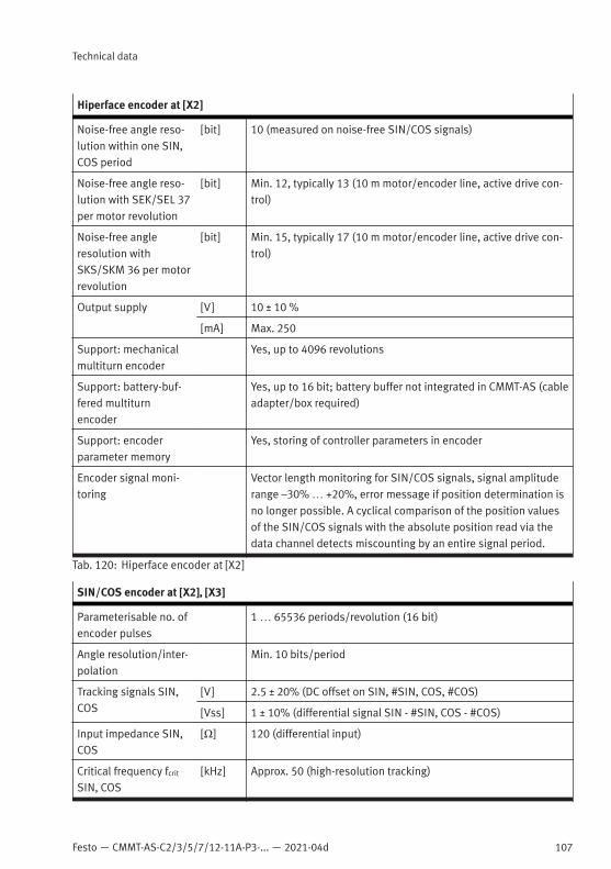
Festo — CMMT-AS-C2/3/5/7/12-11A-P3-... — 2021-04d
Technical data
107
Hiperface encoder at [X2]
Noise-free angle reso-lution within one SIN,COS period
[bit] 10 (measured on noise-free SIN/COS signals)
Noise-free angle reso-lution with SEK/SEL 37per motor revolution
[bit] Min. 12, typically 13 (10 m motor/encoder line, active drive con-trol)
Noise-free angleresolution withSKS/SKM 36 per motorrevolution
[bit] Min. 15, typically 17 (10 m motor/encoder line, active drive con-trol)
Output supply [V] 10 ± 10 %
[mA] Max. 250
Support: mechanicalmultiturn encoder
Yes, up to 4096 revolutions
Support: battery-buf-fered multiturnencoder
Yes, up to 16 bit; battery buffer not integrated in CMMT-AS (cableadapter/box required)
Support: encoderparameter memory
Yes, storing of controller parameters in encoder
Encoder signal moni-toring
Vector length monitoring for SIN/COS signals, signal amplituderange –30% … +20%, error message if position determination isno longer possible. A cyclical comparison of the position valuesof the SIN/COS signals with the absolute position read via thedata channel detects miscounting by an entire signal period.
Tab. 120: Hiperface encoder at [X2]
SIN/COS encoder at [X2], [X3]
Parameterisable no. ofencoder pulses
1 … 65536 periods/revolution (16 bit)
Angle resolution/inter-polation
Min. 10 bits/period
Tracking signals SIN,COS
[V] 2.5 ± 20% (DC offset on SIN, #SIN, COS, #COS)
[Vss] 1 ± 10% (differential signal SIN - #SIN, COS - #COS)
Input impedance SIN,COS
[Ω] 120 (differential input)
Critical frequency fcrit
SIN, COS[kHz] Approx. 50 (high-resolution tracking)
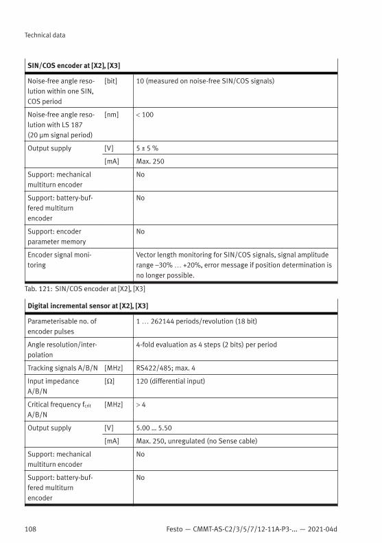
108 Festo — CMMT-AS-C2/3/5/7/12-11A-P3-... — 2021-04d
Technical data
SIN/COS encoder at [X2], [X3]
Noise-free angle reso-lution within one SIN,COS period
[bit] 10 (measured on noise-free SIN/COS signals)
Noise-free angle reso-lution with LS 187(20 µm signal period)
[nm] < 100
Output supply [V] 5 ± 5 %
[mA] Max. 250
Support: mechanicalmultiturn encoder
No
Support: battery-buf-fered multiturnencoder
No
Support: encoderparameter memory
No
Encoder signal moni-toring
Vector length monitoring for SIN/COS signals, signal amplituderange –30% … +20%, error message if position determination isno longer possible.
Tab. 121: SIN/COS encoder at [X2], [X3]
Digital incremental sensor at [X2], [X3]
Parameterisable no. ofencoder pulses
1 … 262144 periods/revolution (18 bit)
Angle resolution/inter-polation
4-fold evaluation as 4 steps (2 bits) per period
Tracking signals A/B/N [MHz] RS422/485; max. 4
Input impedanceA/B/N
[Ω] 120 (differential input)
Critical frequency fcrit
A/B/N[MHz] > 4
Output supply [V] 5.00 … 5.50
[mA] Max. 250, unregulated (no Sense cable)
Support: mechanicalmultiturn encoder
No
Support: battery-buf-fered multiturnencoder
No
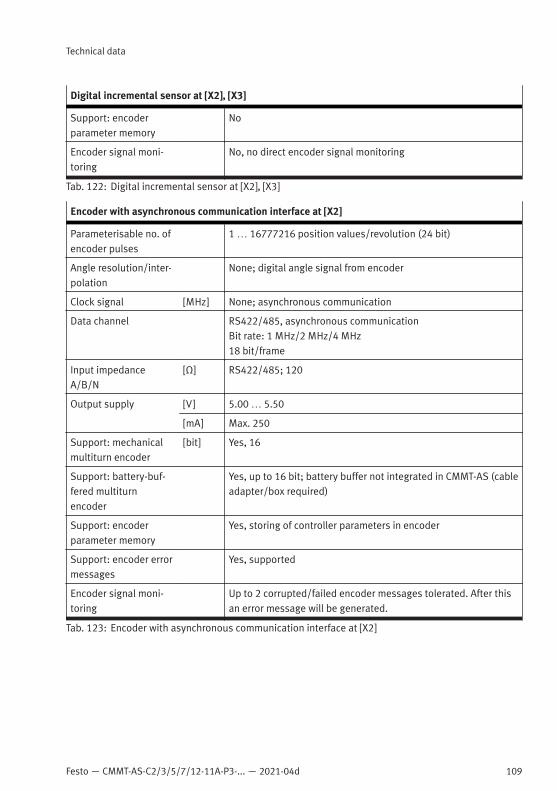
Festo — CMMT-AS-C2/3/5/7/12-11A-P3-... — 2021-04d
Technical data
109
Digital incremental sensor at [X2], [X3]
Support: encoderparameter memory
No
Encoder signal moni-toring
No, no direct encoder signal monitoring
Tab. 122: Digital incremental sensor at [X2], [X3]
Encoder with asynchronous communication interface at [X2]
Parameterisable no. ofencoder pulses
1 … 16777216 position values/revolution (24 bit)
Angle resolution/inter-polation
None; digital angle signal from encoder
Clock signal [MHz] None; asynchronous communication
Data channel RS422/485, asynchronous communicationBit rate: 1 MHz/2 MHz/4 MHz18 bit/frame
Input impedanceA/B/N
[Ω] RS422/485; 120
Output supply [V] 5.00 … 5.50
[mA] Max. 250
Support: mechanicalmultiturn encoder
[bit] Yes, 16
Support: battery-buf-fered multiturnencoder
Yes, up to 16 bit; battery buffer not integrated in CMMT-AS (cableadapter/box required)
Support: encoderparameter memory
Yes, storing of controller parameters in encoder
Support: encoder errormessages
Yes, supported
Encoder signal moni-toring
Up to 2 corrupted/failed encoder messages tolerated. After thisan error message will be generated.
Tab. 123: Encoder with asynchronous communication interface at [X2]

110 Festo — CMMT-AS-C2/3/5/7/12-11A-P3-... — 2021-04d
Technical data
10.2.7 Inputs, outputs, ready contact at [X1A]
Operating ranges of digital inputs drawing current
Fig. 27: Operating ranges of digital inputs drawing current
Control inputs #STO-A and #STO-B at [X1A]
Specification Based on type 3 to EN 61131-2; deviating current consumption
Nominal voltage [V DC] 24
Permissible voltagerange1)
[V DC] –3 … 30
Max. input voltagehigh-level (UH max)
[V] 28.8
Min. input voltagehigh-level (UH min)
[V] 17
Max. input voltage low-level (UL max)
[V] 5
Min. input voltage low-level (UL min)
[V] –3
Max. input current withhigh-level (IH max)
[mA] 75
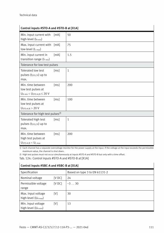
Festo — CMMT-AS-C2/3/5/7/12-11A-P3-... — 2021-04d
Technical data
111
Control inputs #STO-A and #STO-B at [X1A]
Min. input current withhigh-level (IH min)
[mA] 50
Max. input current withlow-level (IL max)
[mA] 75
Min. input current intransition range (IT min)
[mA] 1.5
Tolerance for low test pulses
Tolerated low testpulses (tSTO,TP) up tomax.
[ms] 1
Min. time betweenlow test pulses atUH min < USTO-A/B £ 20 V
[ms] 200
Min. time betweenlow test pulses atUSTO-A/B > 20 V
[ms] 100
Tolerance for high test pulses2)
Tolerated high testpulses (tSTO,TP) up tomax.
[ms] 1
Min. time betweenhigh test pulses atUSTO-A/B < UL max
[ms] 200
1) Each channel has a separate overvoltage monitor for the power supply at the input. If the voltage at the input exceeds the permissiblemaximum value, the channel is shut down.
2) High test pulses must not occur simultaneously at inputs #STO-A and #STO-B but only with a time offset.
Tab. 124: Control inputs #STO-A and #STO-B at [X1A]
Control inputs #SBC-A and #SBC-B at [X1A]
Specification Based on type 3 to EN 61131-2
Nominal voltage [V DC] 24
Permissible voltagerange
[V DC] –3 … 30
Max. input voltagehigh-level (UH max)
[V] 30
Min. input voltagehigh-level (UH min)
[V] 13
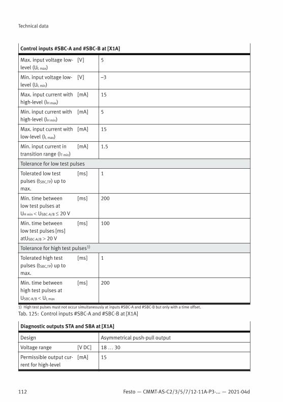
112 Festo — CMMT-AS-C2/3/5/7/12-11A-P3-... — 2021-04d
Technical data
Control inputs #SBC-A and #SBC-B at [X1A]
Max. input voltage low-level (UL max)
[V] 5
Min. input voltage low-level (UL min)
[V] –3
Max. input current withhigh-level (IH max)
[mA] 15
Min. input current withhigh-level (IH min)
[mA] 5
Max. input current withlow-level (IL max)
[mA] 15
Min. input current intransition range (IT min)
[mA] 1.5
Tolerance for low test pulses
Tolerated low testpulses (tSBC,TP) up tomax.
[ms] 1
Min. time betweenlow test pulses atUH min < USBC-A/B £ 20 V
[ms] 200
Min. time betweenlow test pulses [ms]atUSBC-A/B > 20 V
[ms] 100
Tolerance for high test pulses1)
Tolerated high testpulses (tSBC,TP) up tomax.
[ms] 1
Min. time betweenhigh test pulses atUSBC-A/B < UL max
[ms] 200
1) High test pulses must not occur simultaneously at inputs #SBC-A and #SBC-B but only with a time offset.
Tab. 125: Control inputs #SBC-A and #SBC-B at [X1A]
Diagnostic outputs STA and SBA at [X1A]
Design Asymmetrical push-pull output
Voltage range [V DC] 18 … 30
Permissible output cur-rent for high-level
[mA] 15

Festo — CMMT-AS-C2/3/5/7/12-11A-P3-... — 2021-04d
Technical data
113
Diagnostic outputs STA and SBA at [X1A]
Voltage loss at high-level
[V] < 3
Permissible output cur-rent at low-level1)
[mA] < –400
Voltage loss at low-level
[V] < 1.5
Pull-down resistance [kΩ] < 50
Protective function – Short-circuit proof– Feedback-proof– Overvoltage-resistant up to 60 V
Loads
Ohmic load (min.) [kΩ] 1.2
Inductive load [µH] < 10
Capacitive load2) [nF] < 10
Test pulses
Test pulses at outputs None (for time-offset test pulses on the associated A/B controlinputs)
1) Current flows from outside via the internal low-side switch to 0 V reference potential of 24 V supply2) Requires connection of the output to a Type 3 input
Tab. 126: Diagnostic outputs STA and SBA at [X1A]
Digital inputs at [X1A] without safety inputs
Specification Based on type 3 to EN 61131-2; deviating current consumption
Nominal voltage [V DC] 24
Permissible voltagerange
[V DC] −3 … 30
Max. input voltagehigh-level (UH max)
[V] 30
Min. input voltagehigh-level (UH min)
[V] 13
Max. input voltage low-level (UL max)
[V] 5
Min. input voltage low-level (UL min)
[V] –3
Max. input current withhigh-level (IH max)
[mA] 15

114 Festo — CMMT-AS-C2/3/5/7/12-11A-P3-... — 2021-04d
Technical data
Digital inputs at [X1A] without safety inputs
Min. input current withhigh-level (IH min)
[mA] 5
Max. input current withlow-level (IL max)
[mA] 15
Min. input current intransition range (IT min)
[mA] 1.5
Data for inputs CAP0, CAP1
Delay time in the hard-ware
[µs] < 2
Min. permissible pulselength (high or low)
[µs] 10
Time resolution/accu-racy (high or low)
[µs] < 1
Tolerance for low testpulses
No
Data for remaining inputs
Delay time in the hard-ware
[µs] < 200
Min. permissible pulselength (high or low)
[µs] 1000
Tolerance for low testpulses
[ms] 1
Min. period lengthbetween test pulses
[ms] 100
Tab. 127: Digital inputs at [X1A] without safety inputs
Digital trigger outputs TRG0 and TRG1 at [X1A]
Design High-side switch without test pulse monitoring
Voltage range [V DC] 18 … 30
Permissible output cur-rent for high-level
[mA] 20
Protective function – Short-circuit proof– Feedback-proof to 30 V– Automatic switch-off in event of over-temperature (> 150°C)
Loads
Ohmic load (min.) [kΩ] 1.2
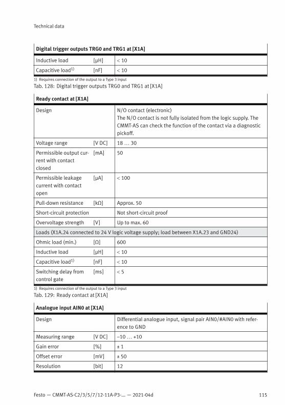
Festo — CMMT-AS-C2/3/5/7/12-11A-P3-... — 2021-04d
Technical data
115
Digital trigger outputs TRG0 and TRG1 at [X1A]
Inductive load [µH] < 10
Capacitive load1) [nF] < 10
1) Requires connection of the output to a Type 3 input
Tab. 128: Digital trigger outputs TRG0 and TRG1 at [X1A]
Ready contact at [X1A]
Design N/O contact (electronic)The N/O contact is not fully isolated from the logic supply. TheCMMT-AS can check the function of the contact via a diagnosticpickoff.
Voltage range [V DC] 18 … 30
Permissible output cur-rent with contactclosed
[mA] 50
Permissible leakagecurrent with contactopen
[µA] < 100
Pull-down resistance [kΩ] Approx. 50
Short-circuit protection Not short-circuit proof
Overvoltage strength [V] Up to max. 60
Loads (X1A.24 connected to 24 V logic voltage supply; load between X1A.23 and GND24)
Ohmic load (min.) [Ω] 600
Inductive load [µH] < 10
Capacitive load1) [nF] < 10
Switching delay fromcontrol gate
[ms] < 5
1) Requires connection of the output to a Type 3 input
Tab. 129: Ready contact at [X1A]
Analogue input AIN0 at [X1A]
Design Differential analogue input, signal pair AIN0/#AIN0 with refer-ence to GND
Measuring range [V DC] –10 … +10
Gain error [%] ± 1
Offset error [mV] ± 50
Resolution [bit] 12

116 Festo — CMMT-AS-C2/3/5/7/12-11A-P3-... — 2021-04d
Technical data
Analogue input AIN0 at [X1A]
Input bandwidth [kHz] 2
Input impedance [kΩ] Approx. 70
In-phase suppression [dB] Approx. 40 (in in-phase voltage range ± 12 V to GND)
Input capacitance [nF] Typically 1 (for 1 kΩ)
Permissible voltagerange
[V DC] –30 … 30
Tab. 130: Analogue input AIN0 at [X1A]
10.2.8 Inputs and outputs for the axis [X1C]
Inputs LIM0, LIM1 at [X1C]
Specification Based on type 3 to EN 61131-2; deviating current consumption
Nominal voltage [V] 24
Permissible voltagerange
[V] –3 … 30
Max. input voltage,high level (UH max)
[V] 30
Min. input voltage,high level (UH min)
[V] 13
Max. input voltage, lowlevel (UL max)
[V] 5
Min. input voltage, lowlevel (UL min)
[V] –3
Max. input current withhigh level (IH max)
[mA] 15
Min. input current withhigh level (IH min)
[mA] 5
Max. input current withlow level (IL max)
[mA] 15
Min. input current intransition range (IT min)
[mA] 1.5
Delay time in the hard-ware
[µs] < 200
Min. permissible pulselength (high or low)
[µs] 1000
Tolerance for low testpulses
[ms] 1.5
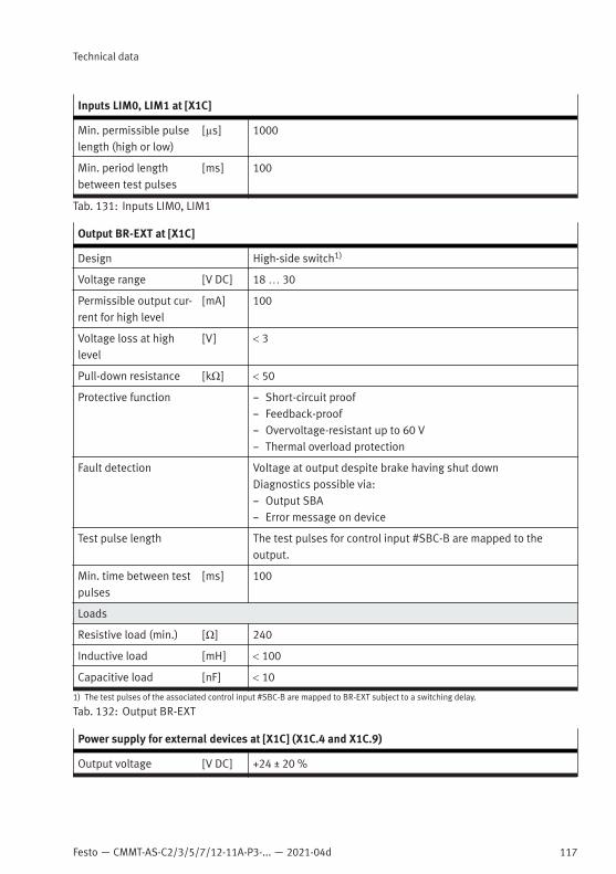
Festo — CMMT-AS-C2/3/5/7/12-11A-P3-... — 2021-04d
Technical data
117
Inputs LIM0, LIM1 at [X1C]
Min. permissible pulselength (high or low)
[µs] 1000
Min. period lengthbetween test pulses
[ms] 100
Tab. 131: Inputs LIM0, LIM1
Output BR-EXT at [X1C]
Design High-side switch1)
Voltage range [V DC] 18 … 30
Permissible output cur-rent for high level
[mA] 100
Voltage loss at highlevel
[V] < 3
Pull-down resistance [kΩ] < 50
Protective function – Short-circuit proof– Feedback-proof– Overvoltage-resistant up to 60 V– Thermal overload protection
Fault detection Voltage at output despite brake having shut downDiagnostics possible via:– Output SBA– Error message on device
Test pulse length The test pulses for control input #SBC-B are mapped to theoutput.
Min. time between testpulses
[ms] 100
Loads
Resistive load (min.) [Ω] 240
Inductive load [mH] < 100
Capacitive load [nF] < 10
1) The test pulses of the associated control input #SBC-B are mapped to BR-EXT subject to a switching delay.
Tab. 132: Output BR-EXT
Power supply for external devices at [X1C] (X1C.4 and X1C.9)
Output voltage [V DC] +24 ± 20 %
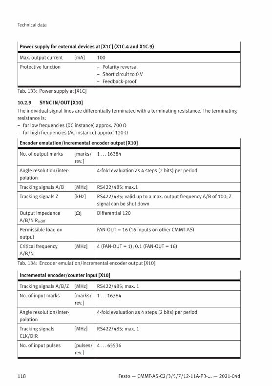
118 Festo — CMMT-AS-C2/3/5/7/12-11A-P3-... — 2021-04d
Technical data
Power supply for external devices at [X1C] (X1C.4 and X1C.9)
Max. output current [mA] 100
Protective function – Polarity reversal– Short circuit to 0 V– Feedback-proof
Tab. 133: Power supply at [X1C]
10.2.9 SYNC IN/OUT [X10]
The individual signal lines are differentially terminated with a terminating resistance. The terminatingresistance is:– for low frequencies (DC instance) approx. 700 Ω– for high frequencies (AC instance) approx. 120 Ω
Encoder emulation/incremental encoder output [X10]
No. of output marks [marks/rev.]
1 … 16384
Angle resolution/inter-polation
4-fold evaluation as 4 steps (2 bits) per period
Tracking signals A/B [MHz] RS422/485; max.1
Tracking signals Z [kHz] RS422/485; valid up to a max. output frequency A/B of 100; Zsignal can be shut down
Output impedanceA/B/N Ra.diff
[Ω] Differential 120
Permissible load onoutput
FAN-OUT = 16 (16 inputs on other CMMT-AS)
Critical frequencyA/B/N
[MHz] 4 (FAN-OUT = 1); 0.1 (FAN-OUT = 16)
Tab. 134: Encoder emulation/incremental encoder output [X10]
Incremental encoder/counter input [X10]
Tracking signals A/B/Z [MHz] RS422/485; max. 1
No. of input marks [marks/rev.]
1 … 16384
Angle resolution/inter-polation
4-fold evaluation as 4 steps (2 bits) per period
Tracking signalsCLK/DIR
[MHz] RS422/485; max. 1
No. of input pulses [pulses/rev.]
4 … 65536

Festo — CMMT-AS-C2/3/5/7/12-11A-P3-... — 2021-04d
Technical data
119
Incremental encoder/counter input [X10]
Tracking signalsCW/CCW
[MHz] RS422/485; max. 1
No. of input pulses [pulses/rev.]
4 … 65536
Input impedanceA/B/N Re.diff
[Ω] Differential 120 in series with 120 pF high-frequency signal ter-mination, additionally 700 parallel, low-frequency signal termi-nation
Tab. 135: Incremental encoder/counter input [X10]
10.2.10 Standard Ethernet [X18], parameterisation interface
Standard Ethernet [X18], parameterisation interface
Design To IEEE 802.3:2012-001)
Connection design RJ45
Transmission rate [Mbit/s] 10/100 (full/half duplex)
Supported protocols TCP/IP
IP address set at fac-tory (presetting)
192.168.0.1
1) Restriction: The interface is galvanically isolated and intended for use with limited cable lengths. Deviating from IEEE 802.3, theisolation coordination is therefore done according to the valid product standard IEC 61800-5-1: DVC A, system voltage ≤ 50 V.
Tab. 136: Standard Ethernet [X18]
10.2.11 Real-time Ethernet [X19] ([XF1 IN], [XF2 OUT])
Real-time Ethernet [X19] ([XF1 IN], [XF1 OUT])
Design RTE communication, physical level in accordance withIEEE 802.3: 2012-001)
Bus connection design[XF1 IN]
RJ45
Bus connection design[XF2 OUT]
RJ45
Max. transmission rate [Mbit/s] 100
Bus protocol EtherCAT: CMMT-AS-...-EC
Protocol – CoE (CANopen over EtherCAT)– EoE (Ethernet over EtherCATEtherCAT)– FoE (File Access over EtherCAT)
Communication profile – CiA 402
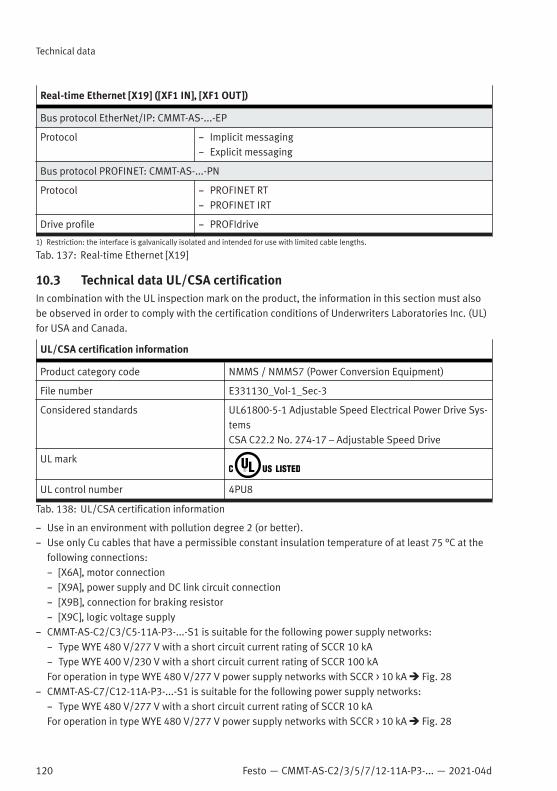
120 Festo — CMMT-AS-C2/3/5/7/12-11A-P3-... — 2021-04d
Technical data
Real-time Ethernet [X19] ([XF1 IN], [XF1 OUT])
Bus protocol EtherNet/IP: CMMT-AS-...-EP
Protocol – Implicit messaging– Explicit messaging
Bus protocol PROFINET: CMMT-AS-...-PN
Protocol – PROFINET RT– PROFINET IRT
Drive profile – PROFIdrive
1) Restriction: the interface is galvanically isolated and intended for use with limited cable lengths.
Tab. 137: Real-time Ethernet [X19]
10.3 Technical data UL/CSA certificationIn combination with the UL inspection mark on the product, the information in this section must alsobe observed in order to comply with the certification conditions of Underwriters Laboratories Inc. (UL)for USA and Canada.
UL/CSA certification information
Product category code NMMS / NMMS7 (Power Conversion Equipment)
File number E331130_Vol-1_Sec-3
Considered standards UL61800-5-1 Adjustable Speed Electrical Power Drive Sys-temsCSA C22.2 No. 274-17 – Adjustable Speed Drive
UL mark
UL control number 4PU8
Tab. 138: UL/CSA certification information
– Use in an environment with pollution degree 2 (or better).– Use only Cu cables that have a permissible constant insulation temperature of at least 75 °C at the
following connections:– [X6A], motor connection– [X9A], power supply and DC link circuit connection– [X9B], connection for braking resistor– [X9C], logic voltage supply
– CMMT-AS-C2/C3/C5-11A-P3-...-S1 is suitable for the following power supply networks:– Type WYE 480 V/277 V with a short circuit current rating of SCCR 10 kA– Type WYE 400 V/230 V with a short circuit current rating of SCCR 100 kAFor operation in type WYE 480 V/277 V power supply networks with SCCR > 10 kA è Fig. 28
– CMMT-AS-C7/C12-11A-P3-...-S1 is suitable for the following power supply networks:– Type WYE 480 V/277 V with a short circuit current rating of SCCR 10 kAFor operation in type WYE 480 V/277 V power supply networks with SCCR > 10 kA è Fig. 28

Festo — CMMT-AS-C2/3/5/7/12-11A-P3-... — 2021-04d
Technical data
121
– Permissible and impermissible mains types of system earthing:– According to the UL standard, the TT system with separate neutral conductor and PE conductor is
not permitted in the overall system.– UL: The integrated semiconductor short-circuit protection does not protect the downstream power
circuit. The power circuit must be protected in conformity with the National Electrical Code and allother local regulations.CSA: The integrated semiconductor short-circuit protection does not protect the downstream powercircuit. The power circuit must be protected in conformity with the Canadian Electrical Code, part I.
Requirements for circuit breakers (automatic circuit breakers) and fuses
Overcurrent protective device Circuit breaker Class J Fuse onlyCMMT-AS-C2/C3/C5-11A-P3
max. permissible ratedcurrent
[A] 30 25
Short circuit currentrating SCCR of mainsfuse
[kA] min. 10 min. 100
Rated voltage [V AC] 480 600
Tab. 139: Requirements for circuit breakers and fuses
Line protection requirements
Description Cable cross sectionat [X9A]
Mains fuse [A]1)
[mm²] CMMT-AS-...-C2/C3/C5/C7/C12-11A-P3...
Minimum fuse pro-tection
1.5 CMMT-AS-C2/C3/C5-11A-P3: 6CMMT-AS-C7/C12-11A-P3: 15
Maximum fuse protection of an individual device or a device group
without heat-resistant cable
4 20
6 30
1) Specifications according to UL 61800-5-1:2012; for cUL, only use Cu cables that have a permissible constant insulation temperatureof at least 75 °C.
Tab. 140: Line protection requirements
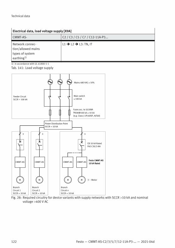
122 Festo — CMMT-AS-C2/3/5/7/12-11A-P3-... — 2021-04d
Technical data
Electrical data, load voltage supply [X9A]
CMMT-AS- C2 / C3 / C5 / C7 / C12-11A-P3...
Network connec-tion/allowed mainstypes of systemearthing1)
L1 è L2 è L3: TN, IT
1) in accordance with UL 61800-5-1
Tab. 141: Load voltage supply
Fig. 28: Required circuitry for device variants with supply networks with SCCR >10 kA and nominalvoltage >400 V AC

Festo — CMMT-AS-C2/3/5/7/12-11A-P3-... — 2021-04d
Technical data
123
10.4 Operation of the servo drive in the system10.4.1 Cable lengths in combination with Festo motors
The permissible motor cable length depends on the combination of components in use and theirproperties, e.g. from:– Emitted interference and immunity to interference (EMC aspects) è 10.4.1.1 Motor cable lengths
with Festo motors– Voltage for releasing the holding brake in the motor è 10.4.1.2 Holding brake voltage drop– Voltage drop in the motor cable è 10.4.1.3 Voltage drop in the motor cableAll aspects must be taken into account. The resulting shortest cable length is the permissible cablelength of the drive system.
10.4.1.1 Motor cable lengths with Festo motors
With reference to EMC aspects, the following maximum motor cable lengths are permissible for anindividual device in combination with Festo motors:
CMMT-AS... PWM[kHz]
required measures Max. permissible motor cable length [m]
EMMT-AS EMME-AS EMMS-AS
Category C2: operation in the first environment (residential area)
-C2-11A-P3 8 Line choke 10 10 10
-C3-11A-P3-C5-11A-P3
8 – (none) 10 10 10
-C7-11A-P3-C12-11A-P3
8 – (none) 10 10 10
Category C3: operation in the second environment (industrial area)
-C2-11A-P3-C3-11A-P3-C5-11A-P3
8 – (none) 50 25 50
external mains filter 100 100
-C7-11A-P3-C12-11A-P3
8 – (none) 25 25 25
external mains filter 100 100
Tab. 142: Maximum motor cable lengths in combination with Festo motors
Required measures
Measures Description
Line choke(3 x ³ 3.7 mH)
A line choke with three partial windings must be installed for mains supply linesL1, L2 and L3 (3 x ³ 3.7 mH) to comply with the mains harmonics requirementsin accordance with EN 61000-3-2 – accessories.
external mainsfilter
Install a suitable external mains filter - accessories.
Tab. 143: Installation measures to achieve the specified category

124 Festo — CMMT-AS-C2/3/5/7/12-11A-P3-... — 2021-04d
Technical data
Measures for the device compoundIf the devices are used in a device compound with coupled mains supply and DC link coupling, thefollowing applies:– The internal mains filter is sufficient for compliance with category C3 with cable lengths up to 25 m
per servo drive.– An external mains filter is always required to comply with category C3 with cables longer than 25 m.
10.4.1.2 Holding brake voltage drop
The voltage drop on the cables to the holding brake can result in a holding brake in the motor notbeing able to open reliably. Festo recommends calculating the resulting input voltage for the holdingbrake.Formula for calculating the input voltage for the holding brake in the motor UHB
Input voltage for the holding brake UHB
Technical data for servo drive
ULS minimum input voltage at the logic supply of the servo drive
UBR,drop maximum voltage drop from the logic supply to the output for the holding brake
IBR, max maximum output current of the servo drive at the output for the holding brake
Motor cable technical data
rcu Specific resistance of copper (warm cable)
L Cable length
A Cross section of the cable for the holding brake
Motor technical data
UHB, rated Nominal voltage of the holding brake
PHB, rated Nominal power of the holding brake in the motor
Tab. 144: Calculation formula for determining the input voltage for the holding brake
The calculated voltage UHB must be greater than the minimum permissible voltage of the holdingbrake UHB, min.ExampleThe following example shows the calculation of the input voltage for the holding brake for a drivesystem consisting of servo drive CMMT-AS-C5-11A-…, servo motor EMMT-AS-100-L-HS-RMB and motorcable NEBM-M23G15-EH -...- Q10N-R3LEG14 with the following values:– ULS = 22.8 V; application-dependent, permissible range è Tab. 109 Logic voltage supply– UBR,drop = 1.0 V; see technical data for servo drive è Tab. 117 Output of holding brake [X6B],
3-phase devices– IBR,max= 1.5 A; see technical data for servo drive è Tab. 117 Output of holding brake [X6B], 3-phase
devices– rcu (warm cable) = 0.021 Ω mm²/m

Festo — CMMT-AS-C2/3/5/7/12-11A-P3-... — 2021-04d
Technical data
125
– L = 32 m; application-dependent, required length– A = 1.0 mm²; see motor cable– UHB, rated = 24 V; see technical data for motor– PHB, rated = 24 W; see technical data for motor– UHB, min = 21.6 V; see technical data of motor (24 V -10%)
The calculated voltage UHB is less than the minimum permissible voltage UHB, min. The required min-imum voltage is no longer reached. In the example, the required cable length could be achieved byincreasing the logic supply voltage from 22.8 V to 24 V.To calculate the maximum possible cable length L for the correct control of the holding brake, theabove formula can be changed as follows:
10.4.1.3 Voltage drop in the motor cable
The length of the motor cable has an influence on the attainable output voltage on the motor sideunder load conditions. Excessively large voltage drops reduce the maximum achievable rotationalspeed of the drive system.The maximum voltage drop on the phases of the motor cable should not exceed the following values inapplications at maximum current:
Servo drive recommended maximum voltage drop
CMMT-AS-C2/C3/C5/C7/C12-11A-P3(3-phase devices)
36 V
Tab. 145: Maximum voltage drop on the motor phases (recommendation)
Formula for calculating the voltage drop on the motor cable UML
Voltage drop in the motor cable UML
Imax maximum current in the application, e.g. current in the acceleration phase
rcu Specific resistance of copper (warm cable)
L Cable length
A Cross section of the cable (motor phases)
Tab. 146: Calculation formula for determining the voltage drop on the motor cable

126 Festo — CMMT-AS-C2/3/5/7/12-11A-P3-... — 2021-04d
Technical data
ExampleThe following example shows the calculation of the voltage drop on theservo drive CMMT-AS-C5-11A-…, servo motor EMMT-AS-100-L-HS-RMB and motor cableNEBM-M23G15-EH-...-Q10N-R3LEG14 with the following values:– Imax = 12.0 A; application-dependent– rcu (warm cable) = 0.021 Ω mm² / m– L = 32 m; application-dependent, required length– A = 2.5 mm²; see power cable motor cable
The calculated voltage drop is less than the recommended limit value. The motor cable thus has asufficient cable cross section.To calculate the maximum possible cable length L based on the voltage drop on the motor cable, theabove formula can be changed as follows:
10.4.2 Power loss
To select a suitable control cabinet, the power losses of the components used must be taken intoaccount (thermal design).The power loss of the servo drive consists of the following:– Power loss of the logic part; independent of the load and the motion profile and can be regarded as
constant– Power dissipation of the power output stage; dependent on the load and the motion profile and the
efficiency of the other components– Power loss in the braking resistorFormula for calculating the average power loss Pv
Mean power loss Pv
ULS,nominal Logic voltage supply at the servo drive
ILS,inactive Current of the logic supply in the inactive status
PMot, avr linear mean value of the electrical output power (average value)
h Efficiency
PBr,avr Mean power loss in the braking resistor
Tab. 147: Calculation formula for determining the average power loss
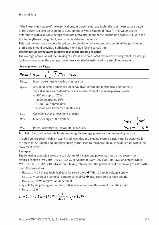
Festo — CMMT-AS-C2/3/5/7/12-11A-P3-... — 2021-04d
Technical data
127
If the linear mean value of the electrical output power is not available, the root mean square valueof the power can also be used for calculation (Root Mean Square of Power). This value can bedetermined with a suitable design tool from Festo after input of the positioning profile, e.g. with thePositioningDrives design tool, see dynamic data for the motor.This root mean square value is based on the calculation of a few support points of the positioningprofile and should provide a sufficiently high value for the calculation.Determination of the average power loss in the braking resistorThe average power loss of the braking resistor is also calculated by the Festo design tool. If a designtool is not available, the average power loss can also be estimated in a simplified manner:
Mean power loss PBr,avg
PBr,avg Mean power loss in the braking resistor
hsystem Assumed overall efficiency for servo drive, motor and mechanical components.Typical values for toothed belt axes as a function of the average drive power:– 500 W: approx. 70%– 2000 W: approx. 80%– > 2000 W: approx. 85%The values are lower for spindle axes.
tcycle Cycle time of the movement process
Wkin Kinetic energy of the system
Wpot Potential energy in the system, e.g. z-axis
Tab. 148: Calculation formula for determining the average power loss in the braking resistor
In doing so, the total moving mass, including slides and moving system parts, must be assumed forthe mass m. All kinetic and potential energies that lead to recuperation must be added up within themovement cycle.ExampleThe following example shows the calculation of the average power loss for a drive system con-sisting of servo drive CMMT-AS-C5-11A-…, servo motor EMMT-AS-100-L-HS-RMB and motor cableM23G15-EH-...-Q10N-R3LEG14 without taking into account the power loss of the braking resistor withthe following values:– ULS,nominal = 24 V; see technical data for servo drive è Tab. 109 Logic voltage supply– ILS,inactive = 0.5 A; see technical data for servo drive è Tab. 109 Logic voltage supply– PMot,avr = 370 W; application-dependent– h = 94%; simplifying assumption, efficiency depends on the current operating point– PBr,avr = 10 W

128 Festo — CMMT-AS-C2/3/5/7/12-11A-P3-... — 2021-04d
Technical data
The power loss of the braking resistor only has to be taken into account if the power dissipation inthe control cabinet is effective. An external braking resistor only has to be taken into account if it ismounted in the control cabinet.


© 2021 all rights reserved to Festo SE & Co. KG
Copyright: Festo SE & Co. KG 73734 Esslingen Ruiter Straße 82 Deutschland
Phone: +49 711 347-0
Internet: www.festo.com