cmax 28/34st i-max 28/32c ba 750/850st, ba 750c„¢ 28/32c ba 750/850st, ba 750c service manual...
TRANSCRIPT

6/02 revised 12/04 Form Number 56043071
CMAX™ 28/34STI-MAX™ 28/32CBA 750/850ST, BA 750C
SERVICE MANUALAdvance MODELS 56396010, 56397403,56397400, 56397401Nilfisk MODELS 56396011, 56396012,56397402

FORM NO. 56043071 CMAX™ 28/34ST / I-MAX™ 28/32C, BA 750/850ST, BA 750C - 1
GENERAL INFORMATION .................................................................................................................................................. 2 SAFETY INSTRUCTIONS .................................................................................................................................................. 3SPECIFICATIONS & MAINTENANCE ............................................................................................................................. 4-6PM CHECKLIST ............................................................................................................................................................... 7-8KNOW YOUR MACHINE ............................................................................................................................................... 9-13SOLUTION SYSTEM ................................................................................................................................................... 14-19 FUNCTIONAL OVERVIEW .............................................................................................................................................. 14 CIRCUIT OVERVIEW SOLUTION AUTO MODE ............................................................................................................ 15 SOLUTION SYSTEM MAINTENANCE ............................................................................................................................ 16 TROUBLESHOOTING GUIDE ................................................................................................................................... 16-17 SOLUTION SOLENOID VALVE REMOVAL .................................................................................................................... 18 SOLUTION VALVE DISASSEMBLY AND CLEANING .................................................................................................... 18 SOLUTION FILTER REMOVAL ....................................................................................................................................... 18 SOLUTION FLOW CONTROL VALVE REMOVAL .......................................................................................................... 18SCRUB BRUSH SYSTEM ............................................................................................................................................ 20-32 GENERAL BRUSH SYSTEM FUNCTIONAL OVERVIEW ............................................................................................... 20 SPECIAL SCRUB SYSTEM FUNCTIONS ................................................................................................................. 20-21 SCRUB BRUSH SYSTEM TROUBLESHOOTING .................................................................................................... 22-26 SCRUB BRUSH DECK REMOVAL (DISC) ...................................................................................................................... 27 SCRUB BRUSH LIFT ACTUATOR REMOVAL (DISC) .................................................................................................... 27 SCRUB BRUSH MOTOR/GEARBOX REMOVAL (DISC) ................................................................................................ 27 SCRUB BRUSH DECK ASSEMBLY REMOVAL (CYLINDRICAL) .................................................................................. 30 SCRUB BRUSH MOTOR(S) REMOVAL (CYLINDRICAL) .............................................................................................. 30 SCRUB BRUSH BELT REPLACEMENT (CYLINDRICAL) .............................................................................................. 30 SCRUB BRUSH SYSTEM MAINTENANCE (CYLINDRICAL) ......................................................................................... 30 SCRUB BRUSH REMOVAL AND INSTALLATION (CYLINDRICAL) .............................................................................. 30 SCRUB BRUSH LIFT ACTUATOR REMOVAL (CYLINDRICAL) .............................................................................. 30-31RECOVERY SYSTEM.................................................................................................................................................. 33-39 FUNCTIONAL OVERVIEW ........................................................................................................................................ 33-34 VACUUM/RECOVERY SYSTEM MAINTENANCE CHECKLIST ..................................................................................... 35 TROUBLESHOOTING GUIDE ................................................................................................................................... 35-37 MAINTENANCE OF FLOAT CAGE AND FLOAT DUCT ................................................................................................. 38 VACUUM MOTOR REMOVAL ......................................................................................................................................... 38 RECOVERY TANK REMOVAL ........................................................................................................................................ 38SQUEEGEE SYSTEM.................................................................................................................................................. 40-41 SQUEEGEE LIFT LINKAGE ADJUSTMENT ................................................................................................................... 40 SQUEEGEE TOOL BLADE(S) REPLACEMENT ............................................................................................................. 40 SQUEEGEE ADJUSTMENT ............................................................................................................................................ 40WHEEL DRIVE SYSTEM ............................................................................................................................................. 42-51 GENERAL FUNCTIONAL OVERVIEW ............................................................................................................................ 42 TROUBLESHOOTING GUIDE ................................................................................................................................... 43-45 DRIVE MOTOR REMOVAL (ALL MODELS) .................................................................................................................... 47 DRIVE WHEEL REMOVAL (CYLINDRICAL) ................................................................................................................... 47 DRIVE WHEEL REMOVAL (DISC) .................................................................................................................................. 48 CHAIN MAINTENANCE, REMOVAL AND ADJUSTMENT ........................................................................................ 48-49 OPTIONAL PARKING BRAKE OPERATION ................................................................................................................... 49 OPTIONAL BRAKE ASSEMBLY REMOVAL / CALIPER ADJUSTMENT ........................................................................ 49 POTENTIOMETER (5K) TESTING AND REMOVAL ....................................................................................................... 50 POTENTIOMETER INSTALLATION AND ADJUSTMENT ........................................................................................ 50-51 POTENTIOMETER (25K) WHEEL DRIVE SPEED LIMIT TESTING ............................................................................... 51ELECTRICAL SYSTEM ................................................................................................................................................ 52-65 BATTERIES / CHARGERS .............................................................................................................................................. 52 DESCRIPTION OF LOW VOLTAGE CUTOUT FEATURE .............................................................................................. 52 DESCRIPTION OF THE BATTERY CONDITION INDICATORS ..................................................................................... 53 BATTERY CHARGING, MAINTENANCE AND TESTING ......................................................................................... 53-54 ACTUATOR DRIVE NUT ADJUSTMENT .................................................................................................................. 54-55 FUNCTIONAL OVERVIEW OF MAIN CONTROL BOARD .............................................................................................. 56 DESCRIPTION OF CONTROL PANEL SYSTEM OVERLOAD INDICATORS ................................................................ 56 MAIN CONTROLLER DIAGNOSTIC SERVICE TEST MODE ................................................................................... 57-59 MAIN CONTROL BOARD SPECIAL PROGRAM OPTIONS ..................................................................................... 60-62 ELECTRICAL COMPONENT LOCATION ........................................................................................................................ 63 WIRING DIAGRAM .......................................................................................................................................................... 64 WIRING SCHEMATIC ...................................................................................................................................................... 65
Note: All references to right, left, front, or rear in this manual are as seen from the operator’s stand-point.
TABLE OF CONTENTS
2 - FORM NO. 56043071 CMAX™ 28/34ST / I-MAX™ 28/32C, BA 750/850ST, BA 750C
INTRODUCTIONThis manual will help you get the most from your CMAX™ 28/34ST, I-MAX™ 28/32C, BA 750/850ST & BA 750C. Read it thoroughly before servicingthe machine.Note: Bold numbers and letters in parentheses indicate an item illustrated on pages 9-10.
PARTS AND SERVICERepairs, when required, should be performed by your Authorized Nilfisk-Advance Service Center, who employs factory trained service personnel,and maintains an inventory of Nilfisk-Advance original replacement parts and accessories.
Call the NILFISK-ADVANCE DEALER named below for repair parts or service. Please specify the Model and Serial Number when discussingyour machine.
(Dealer, affix service sticker here.)
NAME PLATEThe Model Number and Serial Number of your machine are shown on the Nameplate on the machine. This information is needed when orderingrepair parts for the machine. Use the space below to note the Model Number and Serial Number of your machine for future reference.
MODEL NUMBER
SERIAL NUMBER
TRANSPORTING THE MACHINE
CAUTION!Before transporting the machine on an open truck or trailer, make sure that . . .• The machine is tied down securely - see tie-down locations (21).• All access doors and covers are secured (tape and strap as needed).
TOWING
CAUTION!If the machine must be towed or pushed, make sure the Master On/Off Key Switch (B) is in the OFF position and do not move themachine faster than a normal walking pace (2-3 mph, 3-5kph) and for short distances only. Note: Disconnecting the wheel drive motorwiring connector will make a disabled machine easier to push.
OTHER MANUALS AVAILABLE FOR YOUR MACHINEThe following manuals are available from the Nilfisk-Advance Literature Service Department (order according to model name and machine’s serialnumber):
• I-MAX™ 28C, 32C / BA 750C / CMAX™ 34ST Parts List - Form Number 56042422• CMAX™ 28ST / BA 750ST / BA 850ST Parts List - Form Number 56042423• All Models covered in this manual Operation Manuals - Form Numbers
56041518 (Danish, Norwegian, Swedish, Finnish)56041519 (English, German, French, Dutch)56041520 (Spanish, Portuguese, Italian, Greek)
GENERAL INFORMATION
FORM NO. 56043071 CMAX™ 28/34ST / I-MAX™ 28/32C, BA 750/850ST, BA 750C - 3
CAUTIONS AND WARNINGSSYMBOLSNilfisk-Advance uses the symbols below to signal potentially dangerous conditions. Read this information carefully and take thenecessary steps to protect personnel and property.
DANGER!Is used to warn of immediate hazards that will cause severe personal injury or death.
WARNING!Is used to call attention to a situation that could cause severe personal injury.
CAUTION!Is used to call attention to a situation that could cause minor personal injury or damage to the machine or other property.
GENERAL SAFETY INSTRUCTIONSSpecific Cautions and Warnings are included to warn you of potential danger of machine damage or bodily harm.
WARNING!• This machine should only be used by properly trained and authorized persons.• Keep sparks, flame and smoking materials away from batteries. Explosive gases are vented during normal operation.• Charging the batteries produces highly explosive hydrogen gas. Charge batteries only in well-ventilated areas, away from open
flame. Do not smoke while charging the batteries.• Remove all jewelry when working near electrical components.• Turn the key switch off (O) and disconnect the batteries before servicing electrical components.• Never work under a machine without safety blocks or stands to support the machine.• Do not dispense flammable cleaning agents, operate the machine on or near these agents, or operate in areas where flammable
liquids exist.• Do not clean this machine with a pressure washer.• Do not operate this machine on ramps or inclines of more than a 2 degree angle.
CAUTION!• This machine is not approved for use on public paths or roads.• This machine is not suitable for picking up hazardous dust.• Use care when using scarifier discs and grinding stones. Nilfisk-Advance will not be held responsible for any damage to floor
surfaces caused by scarifiers or grinding stones.• When operating this machine, ensure that third parties, particularly children, are not endangered.• Before performing any service function, carefully read all instructions pertaining to that function.• Do not leave the machine unattended without first turning the key switch off (O), removing the key and securing the machine’s
parking brake (if equipped).• Turn the key switch off (O) before changing the brushes and before opening any access panels.• Take precautions to prevent hair, jewelry, or loose clothing from becoming caught in moving parts.• Use caution when moving this machine in below freezing temperature conditions. Any water in the solution or recovery tanks
or in the hose lines could freeze.• The batteries must be removed from the machine before the machine is scrapped. The disposal of the batteries should be safely
done in accordance with your local environmental regulations.
SAVE THESE INSTRUCTIONS
GENERAL INFORMATION
4 - FORM NO. 56043071 CMAX™ 28/34ST / I-MAX™ 28/32C, BA 750/850ST, BA 750C
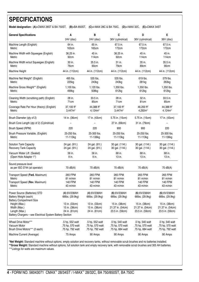
Model designation: (A)=CMAX 28ST & BA 750ST, (B)=BA 850ST, (C)=I-MAX 28C & BA 750C, (D)=I-MAX 32C, (E)=CMAX 34ST
General Specifications A B C D E24V (disc) 24V (disc) 36V (cylindrical) 36V (cylindrical) 36V (disc)
Machine Length (English) 64 in. 65 in. 67.5 in. 67.5 in. 67.5 in. Metric 163cm 165cm 172cm 172cm 172cm
Machine Width with Squeegee (English) 36.25 in. 45 in. 36.25 in. 45 in. 45 in. Metric 92cm 114cm 92cm 114cm 114cm
Machine Width w/out Squeegee (English) 30 in. 35.5 in. 31 in. 35 in. 35.5 in. Metric 76cm 90cm 79cm 89cm 90cm
Machine Height 44 in. (112cm) 44 in. (112cm) 44 in. (112cm) 44 in. (112cm) 44 in. (112cm)
Machine Net Weight* (English) 495 lbs. 535 lbs. 535 lbs. 619 lbs. 579 lbs. Metric 225kg 243kg 243kg 281kg 263kg
Machine Gross Weight** (English) 1,100 lbs. 1,120 lbs. 1,350 lbs. 1,350 lbs. 1,350 lbs. Metric 499kg 508kg 612kg 612kg 612kg
Cleaning Width (scrubbing path) (English) 28 in. 33.5 in. 28 in. 32 in. 33.5 in. Metric 71cm 85cm 71cm 81cm 85cm
Coverage Rate Per Hour (theory) (English) 37,100 ft2 44,388 ft2 37,100 ft2 46,200 ft2 44,388 ft2
Metric 3,447m2 4,124m2 3,447m2 4,292m2 4,124m2
Brush Diameter (qty of 2) 14 in. (36cm) 17 in. (43cm) 5.75 in. (15cm) 5.75 in. (15cm) 17 in. (43cm)
Brush Core Length (qty of 2) (Cylindrical) – – 27 in. (69cm) 31 in. (79cm) –
Brush Speed (RPM) 220 220 900 900 220
Brush Pressure Variable, (English) 25-250 lbs. 25-300 lbs. 25-250 lbs. 25-250 lbs. 25-300 lbs. Metric 11-113kg 11-136kg 11-113kg 11-113kg 11-136kg
Solution Tank Capacity 24 gal. (91l.) 24 gal. (91l.) 30 gal. (114l.) 30 gal. (114l.) 30 gal. (114l.)Recovery Tank Capacity 24 gal. (91l.) 24 gal. (91l.) 30 gal. (114l.) 30 gal. (114l.) 30 gal. (114l.)
Vacuum Water Lift (Sealed) 56 in. 56 in. 68 in. 68 in. 68 in. (Open Hole Adapter 1") 9 in. 9 in. 13 in. 13 in. 13 in.
Sound pressure level as per ISO 3744 (at operator) 70 dB(A) 70 dB(A) 70 dB(A) 70 dB(A) 70 dB(A)
Transport Speed (Fwd. Maximum) 265 FPM 265 FPM 265 FPM 265 FPM 265 FPM Metric 81 m/min 81 m/min 81 m/min 81 m/min 81 m/minTransport Speed (Rev. Maximum) 140 FPM 140 FPM 140 FPM 140 FPM 140 FPM Metric 43 m/min 43 m/min 43 m/min 43 m/min 43 m/min
Power Source (Batteries) STD (4) 6V/238AH (4) 6V/238AH (6) 6V/238AH (6) 6V/238AH (6) 6V/238AHBattery Weight (each) 66lbs. (29.9kg) 66lbs. (29.9kg) 66lbs. (29.9kg) 66lbs. (29.9kg) 66lbs. (29.9kg)Battery Compartment Size Height (Max.) 13 in. (33cm) 13 in. (33cm) 15 in. (38cm) 15 in. (38cm) 15 in. (38cm) Width (Max.) 15 in. (38cm) 15 in. (38cm) 21.37 in. (54cm) 21.37 in. (54cm) 21.37 in. (54cm) Length (Max.) 24 in. (61cm) 24 in. (61cm) 23.5 in. (59cm) 23.5 in. (59cm) 23.5 in. (59cm)Battery Chargers – see Electrical System Battery Section
Wheel Drive Motor*** .5 hp, 552 watt .5 hp, 552 watt .5 hp, 540 watt .5 hp, 540 watt .5 hp, 540 wattVacuum Motor .75 hp, 570 watt .75 hp, 570 watt .75 hp, 570 watt .75 hp, 570 watt .75 hp, 570 wattBrush Drive Motors*** (2 each) .75 hp, 792 watt .75 hp, 792 watt .75 hp, 684 watt .75 hp, 684 watt .75 hp, 792 watt
Machine Current (Average) 75 Amps 90 Amps 90 Amps 90 Amps 90 Amps
*Net Weight: Standard machine without options, empty solution and recovery tanks, without removable scrub brushes and no batteries installed.**Gross Weight: Standard machine without options, full solution tank and empty recovery tank, with removable scrub brushes and 305 AH batteries.***Listings for watts are maximum values.
SPECIFICATIONS

FORM NO. 56043071 CMAX™ 28/34ST / I-MAX™ 28/32C, BA 750/850ST, BA 750C - 5
SPECIFICATIONS
TOP VIEW
SIDE VIEW
Length
Height
WidthSqueegee
Width
6 - FORM NO. 56043071 CMAX™ 28/34ST / I-MAX™ 28/32C, BA 750/850ST, BA 750C
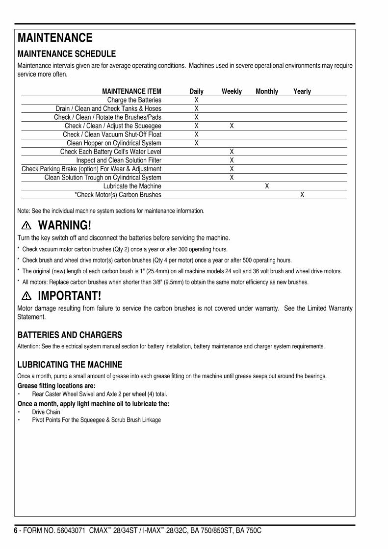
MAINTENANCEMAINTENANCE SCHEDULEMaintenance intervals given are for average operating conditions. Machines used in severe operational environments may requireservice more often.
MAINTENANCE ITEM Daily Weekly Monthly YearlyCharge the Batteries X
Drain / Clean and Check Tanks & Hoses XCheck / Clean / Rotate the Brushes/Pads X
Check / Clean / Adjust the Squeegee X XCheck / Clean Vacuum Shut-Off Float X
Clean Hopper on Cylindrical System XCheck Each Battery Cell’s Water Level X
Inspect and Clean Solution Filter XCheck Parking Brake (option) For Wear & Adjustment X
Clean Solution Trough on Cylindrical System XLubricate the Machine X
*Check Motor(s) Carbon Brushes X
Note: See the individual machine system sections for maintenance information.
WARNING!Turn the key switch off and disconnect the batteries before servicing the machine.
* Check vacuum motor carbon brushes (Qty 2) once a year or after 300 operating hours.
* Check brush and wheel drive motor(s) carbon brushes (Qty 4 per motor) once a year or after 500 operating hours.
* The original (new) length of each carbon brush is 1" (25.4mm) on all machine models 24 volt and 36 volt brush and wheel drive motors.
* All motors: Replace carbon brushes when shorter than 3/8" (9.5mm) to obtain the same motor efficiency as new brushes.
IMPORTANT!Motor damage resulting from failure to service the carbon brushes is not covered under warranty. See the Limited WarrantyStatement.
BATTERIES AND CHARGERSAttention: See the electrical system manual section for battery installation, battery maintenance and charger system requirements.
LUBRICATING THE MACHINEOnce a month, pump a small amount of grease into each grease fitting on the machine until grease seeps out around the bearings.
Grease fitting locations are:• Rear Caster Wheel Swivel and Axle 2 per wheel (4) total.
Once a month, apply light machine oil to lubricate the:• Drive Chain• Pivot Points For the Squeegee & Scrub Brush Linkage
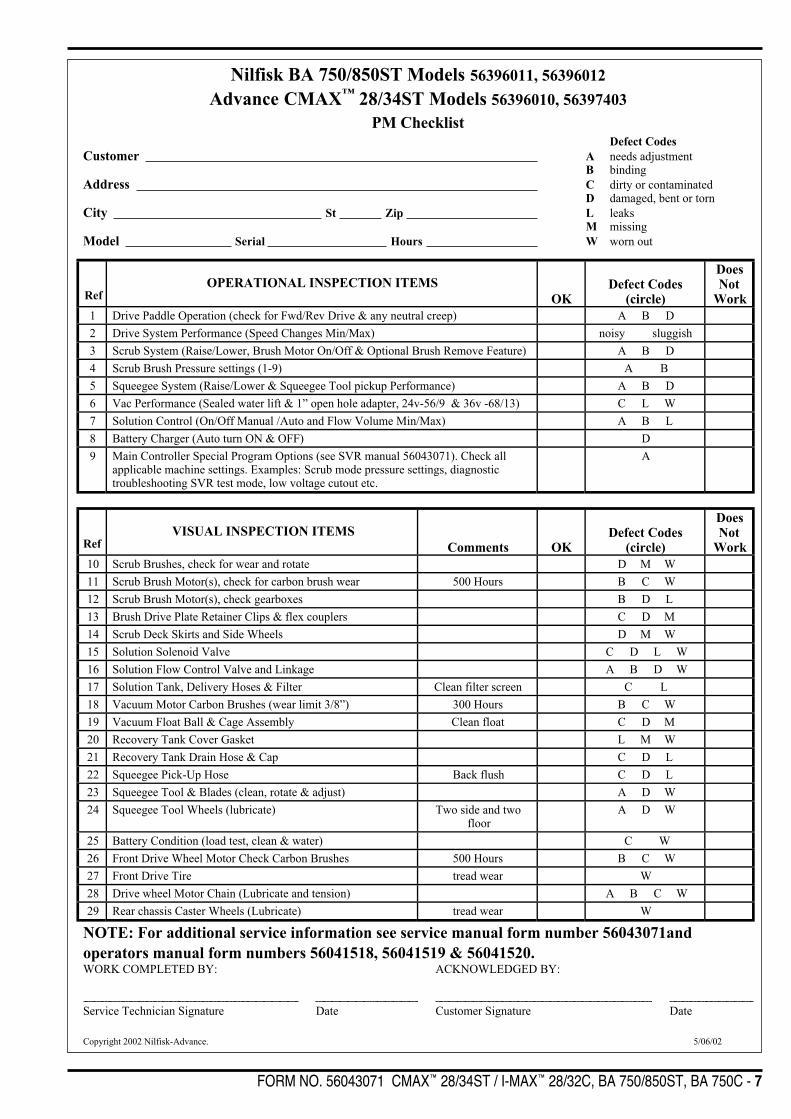
FORM NO. 56043071 CMAX™ 28/34ST / I-MAX™ 28/32C, BA 750/850ST, BA 750C - 7
Copyright 2002 Nilfisk-Advance. 5/06/02
Nilfisk BA 750/850ST Models 56396011, 56396012
Advance CMAX™ 28/34ST Models 56396010, 56397403
PM ChecklistDefect Codes
Customer A needs adjustmentB binding
Address C dirty or contaminatedD damaged, bent or torn
City St Zip L leaksM missing
Model Serial Hours W worn out
RefOPERATIONAL INSPECTION ITEMS
OKDefect Codes
(circle)
DoesNot
Work
1 Drive Paddle Operation (check for Fwd/Rev Drive & any neutral creep) A B D
2 Drive System Performance (Speed Changes Min/Max) noisy sluggish
3 Scrub System (Raise/Lower, Brush Motor On/Off & Optional Brush Remove Feature) A B D
4 Scrub Brush Pressure settings (1-9) A B
5 Squeegee System (Raise/Lower & Squeegee Tool pickup Performance) A B D
6 Vac Performance (Sealed water lift & 1” open hole adapter, 24v-56/9 & 36v -68/13) C L W
7 Solution Control (On/Off Manual /Auto and Flow Volume Min/Max) A B L
8 Battery Charger (Auto turn ON & OFF) D
9 Main Controller Special Program Options (see SVR manual 56043071). Check allapplicable machine settings. Examples: Scrub mode pressure settings, diagnostictroubleshooting SVR test mode, low voltage cutout etc.
A
RefVISUAL INSPECTION ITEMS
Comments OKDefect Codes
(circle)
DoesNot
Work
10 Scrub Brushes, check for wear and rotate D M W
11 Scrub Brush Motor(s), check for carbon brush wear 500 Hours B C W
12 Scrub Brush Motor(s), check gearboxes B D L
13 Brush Drive Plate Retainer Clips & flex couplers C D M
14 Scrub Deck Skirts and Side Wheels D M W
15 Solution Solenoid Valve C D L W
16 Solution Flow Control Valve and Linkage A B D W
17 Solution Tank, Delivery Hoses & Filter Clean filter screen C L
18 Vacuum Motor Carbon Brushes (wear limit 3/8”) 300 Hours B C W
19 Vacuum Float Ball & Cage Assembly Clean float C D M
20 Recovery Tank Cover Gasket L M W
21 Recovery Tank Drain Hose & Cap C D L
22 Squeegee Pick-Up Hose Back flush C D L
23 Squeegee Tool & Blades (clean, rotate & adjust) A D W
24 Squeegee Tool Wheels (lubricate) Two side and twofloor
A D W
25 Battery Condition (load test, clean & water) C W
26 Front Drive Wheel Motor Check Carbon Brushes 500 Hours B C W
27 Front Drive Tire tread wear W
28 Drive wheel Motor Chain (Lubricate and tension) A B C W
29 Rear chassis Caster Wheels (Lubricate) tread wear W
NOTE: For additional service information see service manual form number 56043071and
operators manual form numbers 56041518, 56041519 & 56041520.WORK COMPLETED BY: ACKNOWLEDGED BY:
Service Technician Signature Date Customer Signature Date

8 - FORM NO. 56043071 CMAX™ 28/34ST / I-MAX™ 28/32C, BA 750/850ST, BA 750C
Copyright 2002 Nilfisk-Advance. 5/06/02
Nilfisk BA 750C Model 56397402
Advance I-MAX™ 28/32C Models 56397400, 56397401
PM ChecklistDefect Codes
Customer A needs adjustmentB binding
Address C dirty or contaminatedD damaged, bent or torn
City St Zip L leaksM missing
Model Serial Hours W worn out
RefOPERATIONAL INSPECTION ITEMS
OKDefect Codes
(circle)
DoesNot
Work
1 Drive Paddle Operation (check for Fwd/Rev Drive & any neutral creep) A B D
2 Drive System Performance (Speed Changes Min/Max) noisy sluggish
3 Scrub System (Raise/Lower, Brush Motor On/Off & Optional Brush Remove Feature) A B D
4 Scrub Brush Pressure settings (1-9) A B
5 Squeegee System (Raise/Lower & Squeegee Tool pickup Performance) A B D
6 Vac Performance (Sealed water lift & 1” open hole adapter, 24v-56/9 & 36v -68/13) C L W
7 Solution Control (On/Off Manual /Auto and Flow Volume Min/Max) A B L
8 Battery Charger (Auto turn ON & OFF) D
9 Main Controller Special Program Options (see SVR manual 56043071). Check allapplicable machine settings. Examples: Scrub mode pressure settings, diagnostictroubleshooting SVR test mode, low voltage cutout etc.
A
RefVISUAL INSPECTION ITEMS
Comments OKDefect Codes
(circle)
DoesNot
Work
10 Scrub Brushes, check for wear and rotate Cylindrical brushes D M W
11 Scrub Brush Motor(s), check for carbon brush wear 500 Hours B C W
12 Scrub Brush Motor(s), check drive belts & idler assy’s A B D
13 Scrub Deck, clean debris hopper C D M
14 Scrub Deck Skirts and Side Wheels D M W
15 Solution Solenoid Valve C D L W
16 Solution Flow Control Valve and Linkage A B D W
17 Solution Tank, Delivery Hoses & Filter Clean filter screen C L
18 Vacuum Motor Carbon Brushes (wear limit 3/8”) 300 Hours B C W
19 Vacuum Float Ball & Cage Assembly Clean float C D M
20 Recovery Tank Cover Gasket L M W
21 Recovery Tank Drain Hose & Cap C D L
22 Squeegee Pick-Up Hose Back flush C D L
23 Squeegee Tool & Blades (clean, rotate & adjust) A D W
24 Squeegee Tool Wheels (lubricate) Two side and twofloor
A D W
25 Battery Condition (load test, clean & water) C W
26 Front Drive Wheel Motor Check Carbon Brushes 500 Hours B C W
27 Front Drive Tire tread wear W
28 Drive wheel Motor Chain (Lubricate and tension) A B C W
29 Rear chassis Caster Wheels (Lubricate) tread wear W
NOTE: For additional service information see service manual form number 56043071and
operators manual form numbers 56041518, 56041519 & 56041520.WORK COMPLETED BY: ACKNOWLEDGED BY:
Service Technician Signature Date Customer Signature Date

FORM NO. 56043071 CMAX™ 28/34ST / I-MAX™ 28/32C, BA 750/850ST, BA 750C - 9
1 Solution Tank Fill2 Recovery Tank Cover3 Drive Paddle4 Solution Drain Hose / Level Indicator5 Recovery Drain Hose6 Squeegee Adjustment Bolt7 Squeegee Blade Latch8 Squeegee9 Machine Battery Connector10 Solution Flow Control Knob11 Speed Limit Control Knob
12 Wheel Drive Circuit Breaker (30 Amp)13 Control Circuit Circuit Breaker (5 Amp)14 Brush Deck15 Operator Control Handle16 Operator Hand Brake (optional)17 Squeegee Lever18 Solution Filter19 Hopper (Cylindrical Only)20 Idler Assembly (Cylindrical Only)21 Tie Down Locations (4)
KNOW YOUR MACHINE
1
1
2
3
4
5
78
9
10
11
12
13
14
15
16
6
17
18
1920
21
21

10 - FORM NO. 56043071 CMAX™ 28/34ST / I-MAX™ 28/32C, BA 750/850ST, BA 750C
KNOW YOUR MACHINECONTROL PANELA Scrub Pressure/Hourmeter DisplayB Master On/Off Key SwitchC Solution System IndicatorD Solution ButtonE Vacuum ButtonF Vacuum System IndicatorG Scrub ON / Pressure Increase ButtonH Scrub OFF / Pressure Decrease ButtonI Scrub OFF IndicatorJ Battery Condition Indicator
J
A
B
C
D
EFGHI
FORM NO. 56043071 CMAX™ 28/34ST / I-MAX™ 28/32C, BA 750/850ST, BA 750C - 11
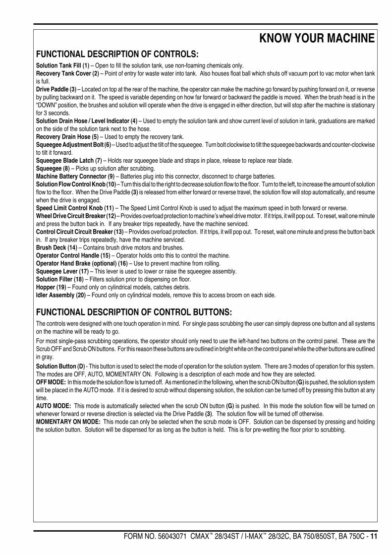
FUNCTIONAL DESCRIPTION OF CONTROLS:Solution Tank Fill (1) – Open to fill the solution tank, use non-foaming chemicals only.Recovery Tank Cover (2) – Point of entry for waste water into tank. Also houses float ball which shuts off vacuum port to vac motor when tankis full.Drive Paddle (3) – Located on top at the rear of the machine, the operator can make the machine go forward by pushing forward on it, or reverseby pulling backward on it. The speed is variable depending on how far forward or backward the paddle is moved. When the brush head is in the“DOWN” position, the brushes and solution will operate when the drive is engaged in either direction, but will stop after the machine is stationaryfor 3 seconds.Solution Drain Hose / Level Indicator (4) – Used to empty the solution tank and show current level of solution in tank, graduations are markedon the side of the solution tank next to the hose.Recovery Drain Hose (5) – Used to empty the recovery tank.Squeegee Adjustment Bolt (6) – Used to adjust the tilt of the squeegee. Turn bolt clockwise to tilt the squeegee backwards and counter-clockwiseto tilt it forward.Squeegee Blade Latch (7) – Holds rear squeegee blade and straps in place, release to replace rear blade.Squeegee (8) – Picks up solution after scrubbing.Machine Battery Connector (9) – Batteries plug into this connector, disconnect to charge batteries.Solution Flow Control Knob (10) – Turn this dial to the right to decrease solution flow to the floor. Turn to the left, to increase the amount of solutionflow to the floor. When the Drive Paddle (3) is released from either forward or reverse travel, the solution flow will stop automatically, and resumewhen the drive is engaged.Speed Limit Control Knob (11) – The Speed Limit Control Knob is used to adjust the maximum speed in both forward or reverse.Wheel Drive Circuit Breaker (12) – Provides overload protection to machine’s wheel drive motor. If it trips, it will pop out. To reset, wait one minuteand press the button back in. If any breaker trips repeatedly, have the machine serviced.Control Circuit Circuit Breaker (13) – Provides overload protection. If it trips, it will pop out. To reset, wait one minute and press the button backin. If any breaker trips repeatedly, have the machine serviced.Brush Deck (14) – Contains brush drive motors and brushes.Operator Control Handle (15) – Operator holds onto this to control the machine.Operator Hand Brake (optional) (16) – Use to prevent machine from rolling.Squeegee Lever (17) – This lever is used to lower or raise the squeegee assembly.Solution Filter (18) – Filters solution prior to dispensing on floor.Hopper (19) – Found only on cylindrical models, catches debris.Idler Assembly (20) – Found only on cylindrical models, remove this to access broom on each side.
FUNCTIONAL DESCRIPTION OF CONTROL BUTTONS:The controls were designed with one touch operation in mind. For single pass scrubbing the user can simply depress one button and all systemson the machine will be ready to go.For most single-pass scrubbing operations, the operator should only need to use the left-hand two buttons on the control panel. These are theScrub OFF and Scrub ON buttons. For this reason these buttons are outlined in bright white on the control panel while the other buttons are outlinedin gray.Solution Button (D) - This button is used to select the mode of operation for the solution system. There are 3 modes of operation for this system.The modes are OFF, AUTO, MOMENTARY ON. Following is a description of each mode and how they are selected.OFF MODE: In this mode the solution flow is turned off. As mentioned in the following, when the scrub ON button (G) is pushed, the solution systemwill be placed in the AUTO mode. If it is desired to scrub without dispensing solution, the solution can be turned off by pressing this button at anytime.AUTO MODE: This mode is automatically selected when the scrub ON button (G) is pushed. In this mode the solution flow will be turned onwhenever forward or reverse direction is selected via the Drive Paddle (3). The solution flow will be turned off otherwise.MOMENTARY ON MODE: This mode can only be selected when the scrub mode is OFF. Solution can be dispensed by pressing and holdingthe solution button. Solution will be dispensed for as long as the button is held. This is for pre-wetting the floor prior to scrubbing.
KNOW YOUR MACHINE

12 - FORM NO. 56043071 CMAX™ 28/34ST / I-MAX™ 28/32C, BA 750/850ST, BA 750C
Vacuum Button (E) - This button is used to select the mode of operation for the vacuum system. There are 3 modes of operation for this system.These modes are OFF, AUTO, ON. Following is a description of each mode and how they are selected.OFF MODE: In this mode the vacuum is off. As mentioned in the following, when the scrub ON button (G) is pushed, the vacuum system will beplaced in the AUTO mode. If it is desired to double-scrub (scrub without recovering the solution) the vacuum system can be turned off by pressingthis button at any time.AUTO MODE: This mode is automatically selected when the scrub ON button (G) is pushed. The vacuum will turn on when the drive paddle (3)is moved forward or reverse. Once the scrub system has been turned OFF, the vacuum will remain ON. To turn the vacuum OFF, press and releasethe vacuum button or the scrub OFF button (H). This will start a ten second delay to allow pick-up of remaining solution. This mode can be selectedindependently of the scrub mode by pressing and releasing the vacuum button.ON MODE: In this mode the vacuum will be on regardless of the drive paddle (3) position. This mode is selected by pressing and holding theVacuum Button (E) for approximately 1.5 seconds. The vacuum mode must first be OFF before entering this mode. This mode is included in theevent an external wand is to be used with this machine or if the operator wants to clean the squeegee using the vacuum hose.Scrub ON / Pressure Increase Button (G) - Pressing the scrub ON button will enable the scrub system and set the scrub pressure to the lastselected value. The status display (A) will display the scrub pressure setting. This is indicated by a number. Subsequent presses of the scrubON button will step the pad pressure setting through the allowable range up to the maximum value of 9. The following will occur when this buttonis pressed:• The scrub deck will be lowered• The vacuum and solution systems will be enabled (vacuum and solution modes = AUTO)• As soon as a direction is commanded by the Drive Paddle (3) (forward or reverse) the brushes will start turning and the vacuum and solution
will turn on.Scrub OFF / Pressure Decrease Button (H) - Momentarily pressing this button will step the pad pressure down to a minimum value of 1. Pressingand holding this button for approximately 1/2 second when the unit is in scrub mode will cause the following to occur:• The status display (A) will indicate “0”• The scrub brushes will turn off• The scrub deck will raise to the UP position• The solution flow will be stopped and the last used pad pressure will be saved• The first time that this button is pressed, the vacuum system will NOT be turned off. This is so that any remaining water may be picked up
without having to turn the vacuum back on. If this button is pressed a second time (pressed after the scrub mode has been turned off) thevacuum will shut off after a 10 second delay.
NOTE: Reducing the pad pressure to “1” and then pressing this button one more time will also turn the scrub system OFF. In this case the lastused pressure will not be saved.NOTE: If the optional Brush Remove Feature is installed, it functions as follows:• To activate the automatic brush removal feature, the scrub deck must be in the UP position and the Drive paddle must be in neutral.• Press and hold the Scrub OFF / Pressure Decrease Button (H) for 1 second. The Scrub OFF Indicator (I) will turn RED and the brush motors
will turn on briefly. The motors will then stop abruptly which will cause the brushes to fall off.
DESCRIPTION OF INDICATORS ON THE CONTROL PANEL:In general, the following guidelines apply to the control panel indicators:A steady red indicator means that the function is inhibited for some reason.A flashing red or yellow indicator means that a fault has occurred in the particular system. An example of this would be an over-current fault.A yellow indicator means that the particular function has been enabled but is not currently on. For example, if the scrub system is activated andthe Drive Paddle (3) is in neutral, the vacuum and solution indicators will all be yellow indicating that the systems are enabled and ready to turnon when the Drive Paddle (3) is moved to forward or reverse.A green indicator means that the particular system is on.A flashing green indicator means that the particular system is in a delayed-off condition. An example of this is when the scrub system is activatedand the Drive Paddle (3) goes from forward or reverse to neutral. When this happens the vacuum indicator will flash green indicating that the vacuumis still on but that it will be turning off after the delay period.Scrub Pressure/Hourmeter Display (A):• The scrub pressure/hourmeter display will scroll the hourmeter information only if all of the systems are turned off and the throttle has been
in neutral for at least ten seconds. The hourmeter information will also be displayed immediately once the key switch has been turned on.• If any of the systems are turned on or the throttle is in forward or reverse, the display will show the relative scrub pressure value (1-9) or
0 if the scrub system is off. This value is a relative indication of scrubbing effort. It is not an absolute indication of the scrub pressure.Solution System Indicator (C):• This indicator will be green if the solution is on.• This indicator will be yellow if the solution is enabled but not turned on.• This indicator will be off if the solution is disabled and turned off.
KNOW YOUR MACHINE
FORM NO. 56043071 CMAX™ 28/34ST / I-MAX™ 28/32C, BA 750/850ST, BA 750C - 13
KNOW YOUR MACHINE
Vacuum System Indicator (F):• This indicator will be green if the vacuum is on.• This indicator will flash green at a slow rate if the ten second delayed turn-off timer is running.• This indicator will be yellow if the vacuum is enabled but not turned on.• This indicator will flash yellow at a fast rate if there is an overload of the vacuum motor.• This indicator will be off if the vacuum is disabled and turned off.Scrub OFF Indicator (I):• This indicator will be green if the scrub system is ready to be turned on.• This indicator will be red if for any reason the scrub system cannot be turned on.• This indicator will flash red at a fast rate if there is an overload of the brush motors or the brush lift actuator motor.• This indicator will be off if the scrub system has been activated.Recovery Tank FULL Indication:• If the recovery tank reaches the full level, the float ball will plug the vacuum inlet which will cause the control system to shut off the scrub,
vacuum, and solution systems. The hour meter/status display (A) will scroll the word “FULL” to indicate that the tank is full.• Pressing the scrub-off/pressure-decrease, scrub-on/pressure-increase, or vacuum buttons will clear the full indication.• The automatic vacuum shutoff feature can be disabled if the vacuum shuts off even when the tank is not full. Refer to the Electrical System
Main Control Board Special Program Options to disable.System Overload Indications:• If the scrub motors or the scrub deck lift actuator become overloaded, the scrub and solution systems will turn off and the scrub-off/pressure-
decrease indicator will flash red at a fast rate (four times per second).• If the vacuum motor becomes overloaded, the scrub, vacuum, and solution systems will turn off and the vacuum indicator will flash yellow
at a fast rate (four times per second).• To reset an overload condition, turn the key switch off and then back on.
DESCRIPTION OF THE BATTERY CONDITION INDICATORAttention: See the Electrical System manual section for the explanation of the battery condition indicator lights.
DESCRIPTION OF THE HOURMETER/STATUS DISPLAYThe single character (LED) display (A) located in the middle of the control panel is primarily used to present the accumulative machine hours ofoperation and the working brush pressure setting. The display is also used to present additional machine information depending upon selecting(entering) special controller program modes. Listed below are some the special program modes.
• Scrub pressure adjustment limits (1-9)• Battery low voltage cutout threshold selection• Main control board software revision level• Scrub brush type motor selection• Recovery tank FULL indicator selection• Brush remove option selection• Service test mode troubleshooting diagnostics
NOTE: Reference in the Electrical System manual section the instructions for programming the special controller options.
DESCRIPTION OF INDICATORS ON THE CONTROL PANEL: (CONTINUED)
14 - FORM NO. 56043071 CMAX™ 28/34ST / I-MAX™ 28/32C, BA 750/850ST, BA 750C
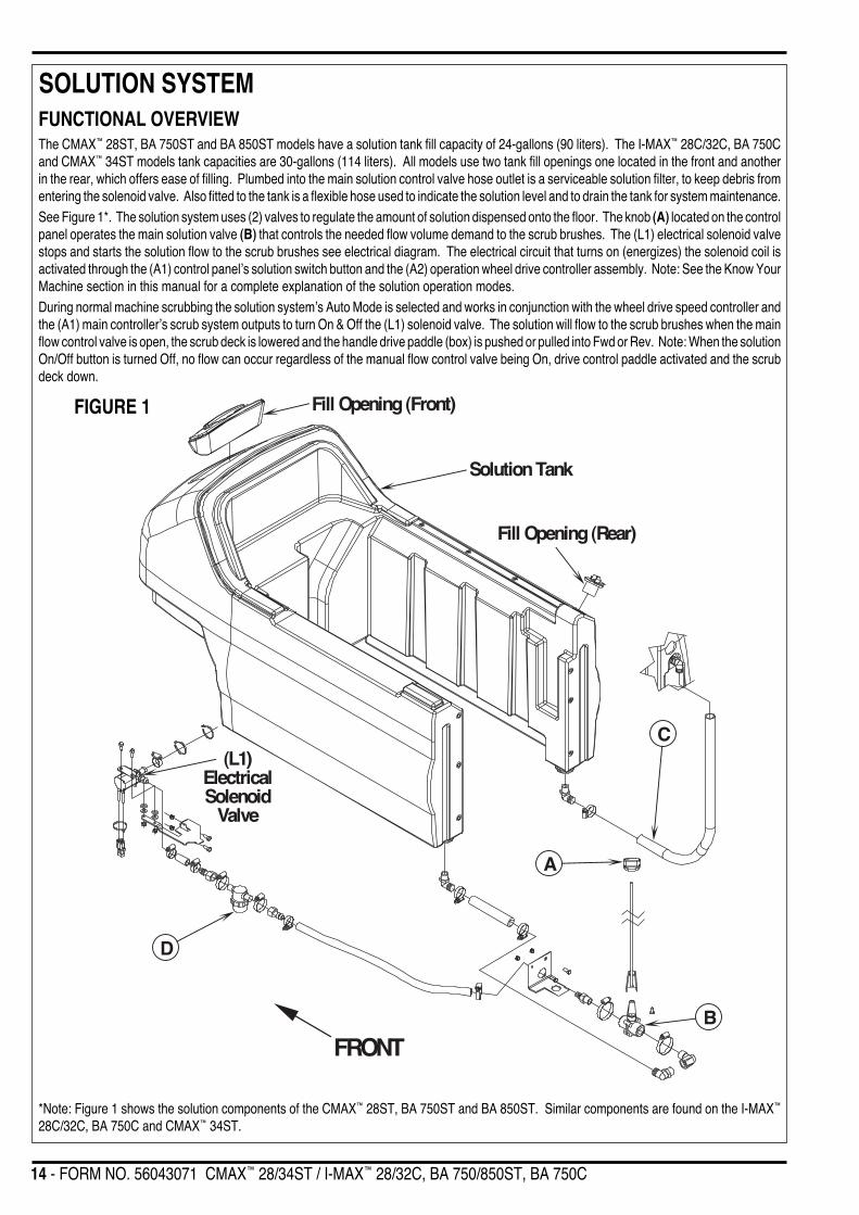
SOLUTION SYSTEM
FRONT
A
B
Fill Opening (Front)
Fill Opening (Rear)
(L1)ElectricalSolenoid
Valve
Solution Tank
C
D
FUNCTIONAL OVERVIEWThe CMAX™ 28ST, BA 750ST and BA 850ST models have a solution tank fill capacity of 24-gallons (90 liters). The I-MAX™ 28C/32C, BA 750Cand CMAX™ 34ST models tank capacities are 30-gallons (114 liters). All models use two tank fill openings one located in the front and anotherin the rear, which offers ease of filling. Plumbed into the main solution control valve hose outlet is a serviceable solution filter, to keep debris fromentering the solenoid valve. Also fitted to the tank is a flexible hose used to indicate the solution level and to drain the tank for system maintenance.See Figure 1*. The solution system uses (2) valves to regulate the amount of solution dispensed onto the floor. The knob (A) located on the controlpanel operates the main solution valve (B) that controls the needed flow volume demand to the scrub brushes. The (L1) electrical solenoid valvestops and starts the solution flow to the scrub brushes see electrical diagram. The electrical circuit that turns on (energizes) the solenoid coil isactivated through the (A1) control panel’s solution switch button and the (A2) operation wheel drive controller assembly. Note: See the Know YourMachine section in this manual for a complete explanation of the solution operation modes.During normal machine scrubbing the solution system’s Auto Mode is selected and works in conjunction with the wheel drive speed controller andthe (A1) main controller’s scrub system outputs to turn On & Off the (L1) solenoid valve. The solution will flow to the scrub brushes when the mainflow control valve is open, the scrub deck is lowered and the handle drive paddle (box) is pushed or pulled into Fwd or Rev. Note: When the solutionOn/Off button is turned Off, no flow can occur regardless of the manual flow control valve being On, drive control paddle activated and the scrubdeck down.
FIGURE 1
*Note: Figure 1 shows the solution components of the CMAX™ 28ST, BA 750ST and BA 850ST. Similar components are found on the I-MAX™
28C/32C, BA 750C and CMAX™ 34ST.
FORM NO. 56043071 CMAX™ 28/34ST / I-MAX™ 28/32C, BA 750/850ST, BA 750C - 15
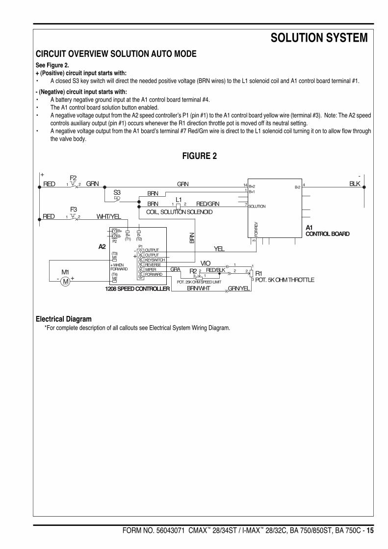
SOLUTION SYSTEMCIRCUIT OVERVIEW SOLUTION AUTO MODESee Figure 2.+ (Positive) circuit input starts with:• A closed S3 key switch will direct the needed positive voltage (BRN wires) to the L1 solenoid coil and A1 control board terminal #1.
- (Negative) circuit input starts with:• A battery negative ground input at the A1 control board terminal #4.• The A1 control board solution button enabled.• A negative voltage output from the A2 speed controller’s P1 (pin #1) to the A1 control board yellow wire (terminal #3). Note: The A2 speed
controls auxiliary output (pin #1) occurs whenever the R1 direction throttle pot is moved off its neutral setting.• A negative voltage output from the A1 board’s terminal #7 Red/Grn wire is direct to the L1 solenoid coil turning it on to allow flow through
the valve body.
FIGURE 2
Electrical Diagram*For complete description of all callouts see Electrical System Wiring Diagram.
+ -BLK
A1CONTROL BOARD
RED GRNF2
1 2
S3GRN 4
B-214 B+21
7 SOLUTIONBRNL1
1 2 RED/GRNCOIL, SOLUTION SOLENOID
FOR
/REV
3
REDF3
1 2 WHT/YEL
BRN
YEL
R1POT. 5K OHM THROTTLE
A2
1208 SPEED CONTROLLER
M1M +-
B-(T2)
B+(T1)
B+B-
P2
(T3)M1
(T4)M2
+ WHENFORWARD
P1
12
123456
OUTPUTOUTPUTKEYSWITCHREVERSEWIPERFORWARD
+-
VIO
BRN/WHT GRN/YEL
1
3
2
POT. 25K OHM SPEED LIMIT
1
223 1
RED/BLKGRA R2
BRN B+1
16 - FORM NO. 56043071 CMAX™ 28/34ST / I-MAX™ 28/32C, BA 750/850ST, BA 750C
SOLUTION SYSTEMSOLUTION SYSTEM MAINTENANCE• Solution Tank: See Figure 1. Weekly empty the solution tank; remove the solution Drain Hose (C) from its storage area (located on the rightrear control handle compartment). Direct the hose to a designated “Disposal Site” and flush the tank with clean water.
• Solution Filter: Remove and clean the inline Solution Filter (D). To access the filter housing for removal, work underneath the middle left sidechassis panel. No tools are needed to remove the filter (hand tighten only). Service Tip: The manual solution control knob must be placed in thefull OFF position. This prevents loss of solution when servicing the filter strainer with a partial or full tank.
• Solution Delivery Trough: On the cylindrical scrub deck clean the holes in the delivery trough to assure even distribution of solution.
TROUBLESHOOTING GUIDE
Problem Possible Cause
Inadequate or no solution flow No solution in the tankMain solution flow control valve knob is in the off positionClogged solution filter, valves and hosesDefective solution solenoid valve (L1)*Solution system fault in the main controller A1*
*Reference the Solution System Troubleshooting Guide flowchart in this manual section for further component diagnostics.
FORM NO. 56043071 CMAX™ 28/34ST / I-MAX™ 28/32C, BA 750/850ST, BA 750C - 17
SOLUTION SYSTEM
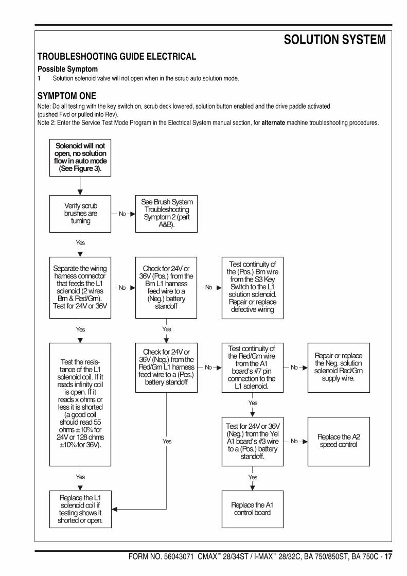
Solenoid will notopen, no solutionflow in auto mode
(See Figure 3).
Verify scrubbrushes are
turning
See Brush SystemTroubleshootingSymptom 2 (part
A&B).
Separate the wiringharness connectorthat feeds the L1solenoid (2 wiresBrn & Red/Grn).
Test for 24V or 36V
Test the resis-tance of the L1
solenoid coil. If itreads infinity coil
is open. If itreads x ohms orless it is shorted
(a good coilshould read 55ohms 10% for
24V or 128 ohms10% for 36V).
Check for 24V or36V (Pos.) from the
Brn L1 harnessfeed wire to a(Neg.) battery
standoff
Replace the L1solenoid coil iftesting shows itshorted or open.
Test continuity ofthe (Pos.) Brn wirefrom the S3 KeySwitch to the L1solution solenoid.Repair or replacedefective wiring
Check for 24V or36V (Neg.) from theRed/Grn L1 harnessfeed wire to a (Pos.)
battery standoff
Test continuity ofthe Red/Grn wire
from the A1board’s #7 pin
connection to theL1 solenoid.
Test for 24V or 36V(Neg.) from the YelA1 board’s #3 wireto a (Pos.) battery
standoff.
Repair or replacethe Neg. solutionsolenoid Red/Grn
supply wire.
Replace the A2speed control
Yes
Replace the A1control board
Yes
Yes
No No
Yes
No
Yes
Yes
No No
Yes
No
TROUBLESHOOTING GUIDE ELECTRICALPossible Symptom1 Solution solenoid valve will not open when in the scrub auto solution mode.
SYMPTOM ONENote: Do all testing with the key switch on, scrub deck lowered, solution button enabled and the drive paddle activated(pushed Fwd or pulled into Rev).Note 2: Enter the Service Test Mode Program in the Electrical System manual section, for alternate machine troubleshooting procedures.

18 - FORM NO. 56043071 CMAX™ 28/34ST / I-MAX™ 28/32C, BA 750/850ST, BA 750C
SOLUTION SYSTEMSOLENOID VALVE REMOVAL1 Drain the solution tank or put the Flow Control Valve Knob (A) (shown in Figure 1) in the full off position to prevent solution loss.2 Remove the lower left side chassis panel (held in place by 3 screws) and the left side scrub brush skirt assembly from the machine.3 See Figure 3. Unplug the L1 solenoid valve wire assembly connection from the machine harness.4 Loosen both the inlet and outlet Hose Clamps (E) and (F) that secure the hoses to the valve body.5 Separate (pry) the solution outlet hose off from its valve body barbed fitting.6 Remove the (2) Hex Screws (G) that secure the valve to the Mount Bracket (H), then pull the valve body to the front separating it from the
solution inlet Hose (I), completing the part removal.
FRONT
E
H
IF
G
Assembly
L
K
J
FIGURE 3
SOLENOID VALVE DISASSEMBLY AND CLEANING1 Remove the solenoid valve. See the Solenoid Valve Removal section for instructions.2 See Figure 3. Remove the (4) (J) Screws and disassemble the valve (be careful not to lose any internal parts).3 Thoroughly wash dirt from block (K) and diaphragm (L).4 After reassembling, test the solenoid valve for proper operation.
SOLUTION FILTER REMOVAL1 Drain the solution tank using the solution drain hose or put the flow control valve knob in the full off position to prevent solution loss.2 See Figure 4A or 4B. Loosen the (2) Hose Clamps (M) and pry off the inlet solution hose from the filter head hose barb fitting.3 Remove the (2) Hose Clamps (N) that secure the filter housing to the Mount Bracket (H), then pull the valve body to the rear separating it
from the solution outlet hose, completing the part removal.
SOLUTION FLOW CONTROL VALVE REMOVAL1 Drain the solution tank using the drain hose.2 See Figure 4A or 4B. Loosen the (2) Hose Clamps (O) and (P) and pry off inlet solution Hose (Q) from the flow control valve.3 Remove the Philips head Screw (R) (using a short handled screwdriver) that secures the operator solution adjustment rod (S) to the ball
valve arm and separate.4 Remove the (2) Nuts (T) & Screws (U) that secure the valve Mount Bracket (V) to the chassis. Then pull the valve and bracket to the rear
separating the valve from the solution outlet Hose (W), completing the part removal.

FORM NO. 56043071 CMAX™ 28/34ST / I-MAX™ 28/32C, BA 750/850ST, BA 750C - 19
SOLUTION SYSTEM
FRONT
M
P
M O S
N
U
R
T
V
P
N
MM
UT
S
V
O
N
N
FRONT
Q
W
H
Q
W
H
R
FIGURE 4B I-MAX™ 28C, I-MAX™ 32C, BA 750C & CMAX™ 34ST
FIGURE 4A CMAX™ 28ST, BA 750ST & BA 850ST
20 - FORM NO. 56043071 CMAX™ 28/34ST / I-MAX™ 28/32C, BA 750/850ST, BA 750C
SCRUB BRUSH SYSTEMFUNCTIONAL OVERVIEW• Disc Brush System OverviewSee Figure 2. The machine models CMAX 28ST, CMAX 34ST, BA 750ST & BA 850ST (model #’s 56396010, 56397403, 56396011 & 56396012)use the disc type scrub system.
• Cylindrical Brush System OverviewSee Figure 4. The machine models I-MAX 28C, I-MAX 32C & BA 750C (model #’s 56397400, 56397401 & 56397402) use two cylindrical brushesthat counter rotate to sweep up light debris and scrub at the same time. Each scrub brush is powered on opposing ends by 3/4 HP permanentmagnet motors attached to separate poly-V belt/pulley drives.
• General Brush OverviewOn all models the scrub deck platform is raised & lowered automatically by a vertically mounted electric lift actuator motor. The operation of themachine’s scrub functions are activated when the operator selects (presses) the scrub (mode) panel buttons. The scrub pad or brush pressureranges (1-9) are selectable allowing the operator the choice to vary the scrubbing effort (pressure) while operating the machine. Note: See theMain Control Board Special Program Options section in this manual for more detailed operation and instructions to change scrub pressure settings.
See Figure 1. The machine’s main scrub system input and output operating functions are regulated (managed) by the display panel and combinedmain control board A1. The major scrub system functions are…
• Scrub Brush Motor Run FunctionControl Circuit Overview Scrub Brush Motor+(Positive) Circuit input starts with:• A closed S3 key switch supplies the needed positive voltage to the K1 brush solenoid coil and the A1 control board #1 terminal (Brn wires).
Note: The A1 control board scrub-on/pressure increase button must also be depressed (enabled). This operator command lowers the brushdeck.
-(Negative) Circuit input starts with:• A battery negative ground input at the A1 control board terminal #4 and at the A2 speed controller terminal B- (T2).• A negative voltage output from the A2 speed controller’s P1 (pin #1) to the A1 control boards yellow wire (#3 terminal). Note: The A2 speed
control auxiliary output (pin #1) occurs whenever the R1 directional/throttle pot is moved off its neutral setting. This operator commandhappens when the drive paddle is pushed or pulled to run the wheel drive motor in Forward or Reverse.
• A negative voltage output from the A1 board’s terminal #5 Vio/Blk wire completes the K1 solenoid coil circuit (Pos. & Neg.) and pulls in theload contact making the brush motors run.
• Scrub Brush Actuator Lift Motor FunctionThe A1 control board outputs (terminals 11 & 12) activate (raise and lower) the scrub-deck for installing, removing and controlling the scrub brushes’selected current load. The large BLK negative (-) scrub brush motor wire is specially designed so that it has a known (specified) resistance value.As brush motor current passes through the negative wire that is, in effect, a low value resistor, a small voltage drop is developed across it whichis proportional to the motor current. This voltage change is inputted to the A1 control board at terminal pins 8 and 2 (sense wires WHT/GRA &GRA/BLK). Any surrounding temperature change in this large Neg. motor wire affects its resistance so the temperature is sensed by a thermistor(*) built into the control board A1. This allows the controller to provide error correction for the temperature resistance changes. When the controllersenses a current draw out of the desired range it automatically turns on the M5 actuator motor to raise or lower the scrub deck. This process ison going in maintaining the operator’s selected scrub motor current load setting to sustain the desired brush working pressure.
• Low Voltage Cut-Out FunctionThe purpose of the special low battery voltage cutout function is to help prolong battery life. The scrub deck will be raised and the brush motorsand solution solenoid valve will turn OFF automatically and cease to function when the batteries discharge to the selected cutout level. The cutoutlevel is adjustable between two settings. The standard setting (wet cell/lead acid) is 1.72 volts per cell and alternate setting (gel/maintenance free)is 1.81 volts per cell. Note: See the battery system section for instructions for selecting (setting) the two different thresholds.
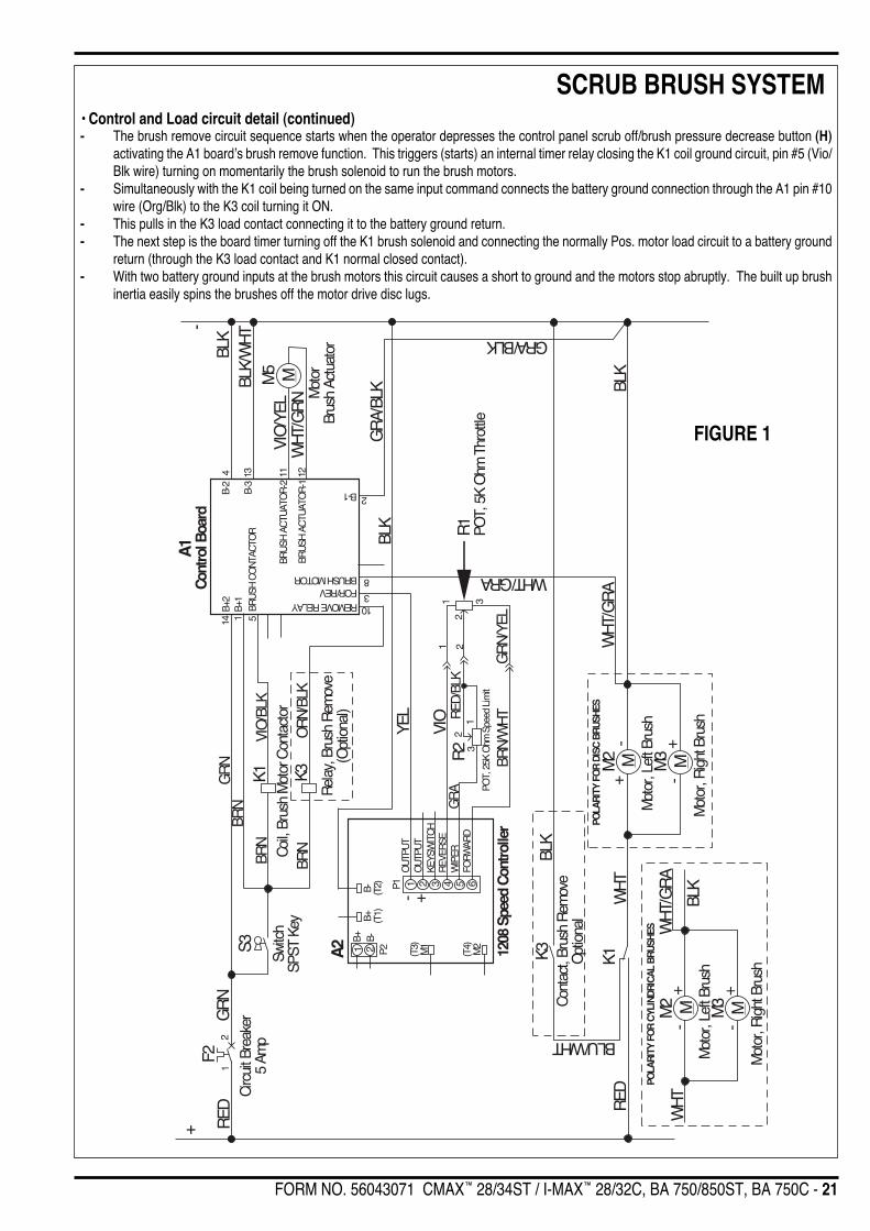
SPECIAL SCRUB SYSTEM FUNCTIONS• Optional Scrub Brush Removal Function (Disc only)For removal of the scrub brushes automatically, the scrub deck must be in the up position and the drive system in neutral. To remove the scrubbrushes simply depress the control panel scrub-off/pressure decrease button (H) for 1 second. The A1 control board will momentarily run the brushmotor and then stop it quickly, where the brush inertia causes the brush to easily spin itself off of the scrub brush motor drive cap.
• Control and Load circuit detail.- A closed S3 key switch supplies the needed positive circuit inputs (Brn wire) to the K1 brush solenoid coil, K3 brush remove solenoid coil
and A1 control board.
FORM NO. 56043071 CMAX™ 28/34ST / I-MAX™ 28/32C, BA 750/850ST, BA 750C - 21
SCRUB BRUSH SYSTEM
M
BLK
A1Co
ntro
l Boa
rd
RED
GR
NF2
12
Circ
uit B
reak
er5
Amp
S3
Switc
hSP
ST K
ey
GR
NBL
K/W
HT
4 13
B-2
B-3
M5 M
VIO
/YEL
WH
T/G
RN M
otor
Brus
h Ac
tuat
or
14B+
21
B+1
BRN
5BR
USH
CO
NTA
CTO
RVI
O/B
LKBR
NK1
Coil,
Bru
sh M
otor
Con
tact
or11 12
BRU
SH A
CTU
ATO
R-2
BRU
SH A
CTU
ATO
R-1
REMOVE RELAYFOR/REVBRUSH MOTOR
B-1
GR
A/BL
K
2
8
310
GRA/BLK
YEL
BLK
WHT/GRA
WH
T/G
RA
BLK
M3
M2 M
Mot
or, R
ight
Bru
sh
Mot
or, L
eft B
rush
POLA
RITY
FO
R DI
SC B
RUSH
ES
+- +
-
R1
POT,
5K
Ohm
Thr
ottle
POLA
RITY
FO
R CY
LIND
RICA
L BR
USHE
S
+-
+-
M3 MM2 M
Mot
or, R
ight
Bru
sh
Mot
or, L
eft B
rush
WH
T/G
RA
BLK
WH
T
WH
T
RED
K1K3
BLU/WHT
Cont
act,
Brus
h R
emov
eO
ptio
nal
A2 1208
Spe
ed C
ontro
ller
B- (T2)
B+ (T1)
B+ B-P2 (T3)
M1
(T4)
M2
P1
1 2
1 2 3 4 5 6
OU
TPU
TO
UTP
UT
KEYS
WIT
CH
REV
ERSE
WIP
ERFO
RW
ARD
+-
VIO
BRN/
WH
TG
RN/
YEL
1 3
2
POT,
25K
Ohm
Spe
ed L
imit
1 22
31R
ED/B
LKG
RA
R2
-+
Rel
ay, B
rush
Rem
ove
(Opt
iona
l)
BRN
OR
N/BL
KK3
BLK
- The brush remove circuit sequence starts when the operator depresses the control panel scrub off/brush pressure decrease button (H)activating the A1 board’s brush remove function. This triggers (starts) an internal timer relay closing the K1 coil ground circuit, pin #5 (Vio/Blk wire) turning on momentarily the brush solenoid to run the brush motors.
- Simultaneously with the K1 coil being turned on the same input command connects the battery ground connection through the A1 pin #10wire (Org/Blk) to the K3 coil turning it ON.
- This pulls in the K3 load contact connecting it to the battery ground return.- The next step is the board timer turning off the K1 brush solenoid and connecting the normally Pos. motor load circuit to a battery ground
return (through the K3 load contact and K1 normal closed contact).- With two battery ground inputs at the brush motors this circuit causes a short to ground and the motors stop abruptly. The built up brush
inertia easily spins the brushes off the motor drive disc lugs.
FIGURE 1
• Control and Load circuit detail (continued)

22 - FORM NO. 56043071 CMAX™ 28/34ST / I-MAX™ 28/32C, BA 750/850ST, BA 750C
SCRUB BRUSH SYSTEMTROUBLESHOOTING GUIDE ELECTRICALPossible Symptoms1 Scrub brush motors and solution solenoid valve do not work2 Scrub brush motors do not work3 Scrub brush auto remove function does not work (optional)
SYMPTOM ONE
No No
Check the batterymeter, is the red
indicator lightflashing
Check the scrubsystem off indicatorlight is it flashing red
or solid red.
See the scrub brushsystem troubleshoot-ing Symptom 2 parts
A and B.
Recharge batterypack (the low volt-
age cutout isfunctioning*)
Yes Yes
Scrub brush motors& solution solenoidvalve do not work
(See Control Panel inKnow Your Machine
section).
**The scrub motoror scrub deck liftactuator is over-
loaded
Inspect the brushes and liftactuator motor for any possi-ble mechanical or electrical
high current draw
Examples • Short circuit motor(s) • Worn carbon brushes • Frozen lift linkage • Restriction on rotation of brush output drive plate gear box etc.
*Reference the Description of the Battery Low Voltage Cutout Feature in the Electrical System of this manual.**When experiencing a scrub system overload, the scrub and solution systems will turn off and the scrub-off/pressure-decrease indicator will flash
red at a fast rate (four times per second). Correct the cause of the overload and to reset, turn the key switch off and then back on.
FORM NO. 56043071 CMAX™ 28/34ST / I-MAX™ 28/32C, BA 750/850ST, BA 750C - 23
SCRUB BRUSH SYSTEM
Yes
No No
Test for 24/36 voltsat the K1 brush sole-noid, test point highcurrent (load) outputwire (WHT) to a bat-
tery ground
Test for 24/36 voltsat the K1 solenoidPos. battery load
input wire (RED) to abattery ground
Repair or replacewiring
Test for 24/36 Voltsat the main brush
motor feed terminalblock WHT (Pos.)and BLK (Neg.)
Yes
See Part B scrubbrush control circuit
troubleshooting Part B
Yes
Test for an opencircuit in each brush
motor. Repair orreplace wiring or
motor(s).
No
Test for voltage onboth load wires, WHT
Pos. to a batteryground and BLK Neg.
to a battery Pos.Repair or replacedefective wiring.
Scrub brushmotors do not work
(See Figure 1).
SYMPTOM TWOScrub Brush Motors Do Not WorkNote: Do all testing with key switch on, scrub on switch activated (scrub deck lowered) and drive paddle activated (pushed Fwd or pulled into Rev).Note 2: Enter the Service Test Mode Program in the Electrical System manual section, for alternate machine troubleshooting procedures.Part A: Scrub Brush Motor Load Circuit Troubleshooting Guide
TROUBLESHOOTING GUIDE (CONTINUED)

24 - FORM NO. 56043071 CMAX™ 28/34ST / I-MAX™ 28/32C, BA 750/850ST, BA 750C
SCRUB BRUSH SYSTEM
SYMPTOM TWOScrub Brush Motors Do Not WorkNote: Do all testing with key switch on, scrub on switch activated (scrub deck lowered) and drive paddle activated (pushed Fwd or pulled into Rev).Part B: Scrub Brush Motor Control Circuit Troubleshooting Guide
TROUBLESHOOTING GUIDE (CONTINUED)
Scrub brushesdon't turn (See
Figure 1).
Replace the K1brush motor
solenoid
Check for 24/36Vat the Pos. K1
BRN coil wire to abattery ground
standoff
Check for 24/36V(Neg.) at the pin #3
(YEL wire) on the A1control board. Note:
The drive paddlemust be activated
(Fwd or Rev) for thespeed control to
close the P1 outputcircuit to battery
ground.
Test BRN coil wiringcontinuity. Repair orreplace the defec-
tive wiring.
Yes
No
Check for 24/36V atthe Neg. K1
VIO/BLK coil wire toa Pos. battery
standoff
No No
Yes
Yes
No
Check for 24/36VNeg. at the YEL P1
pin #1 on the A2speed control
Replace the A2speed control
Repair or replacethe P1 controller
YEL (output) wire.
Replace the A1control board
Yes

FORM NO. 56043071 CMAX™ 28/34ST / I-MAX™ 28/32C, BA 750/850ST, BA 750C - 25
SCRUB BRUSH SYSTEM
SYMPTOM THREEScrub Brush Auto Removal Function Does Not Work (Optional)Note before troubleshooting: Check that the automatic remove function is selected (E) enabled. To do this go into the special program optionsection (electrical system) for instructions to follow to enable or disable the brush remove function.Special Service Note: Read the brush remove function circuit detail in the previous brush system overview sectionTo test: Have the key switch ON, scrub deck raised and the drive system in neutral. Next to remove the brushes simply depress the control panelscrub OFF switch (H) for one second.Note 2: Enter the Service Test Mode Program in the Electrical System manual section, for alternate machine troubleshooting procedures.Part A: Scrub Brush Auto Remove Load Circuit Troubleshooting Guide
TROUBLESHOOTING GUIDE (CONTINUED)
No
Yes
Scrub brush autoremoval function
does not work(See Figure 1).
Check circuit(*) continu-ity across the K3 relay
motor load contact(remove the BLU/WHT &
BLK wires beforetesting). Note the K3
coil relay must be ener-gized, scrub off buttonactivated (for 1 sec.).
Load circuit should testclosed momentarily.
See Part B scrub brushauto remove control
circuit troubleshooting
Check wiring• From the K3 relay tobattery ground (BLK)wire.• From the K3 relay toK1 brush motor solenoid(BLU/WHT) wire.
Repair or replacedefective wiring
*Alternate method to turn on remove relay. See service test mode section and follow the how to control the remove relay under the scrub off/pressure decrease switch explanation.

26 - FORM NO. 56043071 CMAX™ 28/34ST / I-MAX™ 28/32C, BA 750/850ST, BA 750C
SCRUB BRUSH SYSTEM
SYMPTOM THREEScrub Brush Auto Removal Function Does Not Work (Optional)To test: Have the key switch ON, scrub deck raised and the drive system in neutral. Next to remove the brushes simply depress the control panelscrub OFF switch (H) for one second.
Part B: Scrub Brush Auto Remove Control Circuit Troubleshooting Guide
Scrub brush autoremoval function
does not work(See Figure 1).
With the scrub offbutton (H) activated,
check for 24/36Vacross the K3 brushremove relay coil.Wire colors BRN
(pos.) & ORN/BLK(neg.).
Check for 24/36V atthe neg. K3
ORG/BLK coil wireto a pos. battery
standoff.
Yes
No
Using an Ohm metertest resistance, spec.is 400 ohm for 24V
and 830 ohm for 36Vif infinity coil open.
Yes
Yes
Check continuity ofthe ORN/BLK wire,
repair or replace
Test BRN pos relaycoil wire continuity.Repair or replace
wiring
Open in the coilwinding
Replace the K3relay
Check for 24/36V atthe control board
(A1) pin #10 batteryground output to
pos. battery standoff
Replace the A1control boardNo
Check for 24/36V atthe pos. K3 BRNcoil wire to a bat-
tery ground stand-off.
Yes
No
No
Yes
TROUBLESHOOTING GUIDE (CONTINUED)
FORM NO. 56043071 CMAX™ 28/34ST / I-MAX™ 28/32C, BA 750/850ST, BA 750C - 27
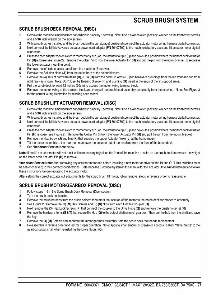
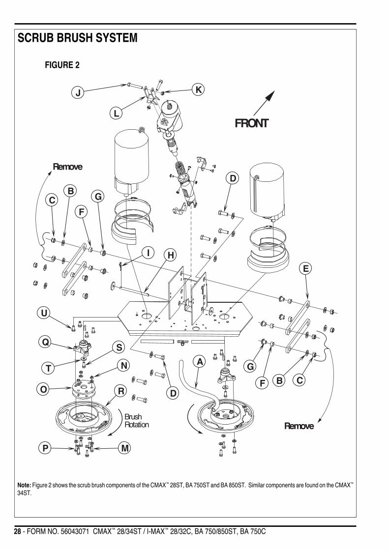
SCRUB BRUSH SYSTEMSCRUB BRUSH DECK REMOVAL (DISC)1 Remove the machine’s molded front panel (held in place by 6 screws). Note: Use a 1/4 inch Allen (hex key) wrench on the front cover screws
and a 5/16 inch wrench on the side screws.2 With scrub brushes installed and the brush deck in the up (storage) position disconnect the actuator motor wiring harness pig tail connector.3 Next connect the Nilfisk-Advance actuator power cord adapter (PN 56407502) to the machine’s battery pack and lift actuator motor pig tail
connector.4 Press the cord adapter rocker switch to momentarily run (jog) the actuator output (up and down) to a position where the bottom deck Actuator
Pin (H) is loose (see Figure 2). Remove the Cotter Pin (I) from the lower Actuator Pin (H) and pull the pin from the mount bracket, to separatethe lower actuator mounting point.
5 Remove the left side chassis panel from the machine (3 screws).6 Remove the Solution Hose (A) from the outlet barb at the solenoid valve.7 Remove the (4) sets of hardware items (B), (C) & (D) from the deck Lift Arms (E) (two hardware groupings from the left front and two from
right rear) as shown. Note: Don’t lose the Bearing Sleeve (F) and Bushing (G) insert in the ends of the lift support arms.8 Pull the scrub deck forward 12 inches (30cm) to access the motor wiring terminal block.9 Remove the motor wiring at the terminal block and then pull the brush head assembly completely from the machine. Note: See Figure 3
for the correct wiring illustration for rewiring each model.
SCRUB BRUSH LIFT ACTUATOR REMOVAL (DISC)1 Remove the machine’s molded front panel (held in place by 6 screws). Note: Use a 1/4 inch Allen (hex key) wrench on the front cover screws
and a 5/16 inch wrench on the side screws.2 With scrub brushes installed and the brush deck in the up (storage) position disconnect the actuator motor wiring harness pig tail connector.3 Next connect the Nilfisk-Advance actuator power cord adapter (PN 56407502) to the machine’s battery pack and lift actuator motor pig tail
connector.4 Press the cord adapter rocker switch to momentarily run (jog) the actuator output (up and down) to a position where the bottom deck Actuator
Pin (H) is loose (see Figure 2). Remove the Cotter Pin (I) from the lower Actuator Pin (H) and pull the pin from the mount bracket.5 Remove the Hex Screw (J) and Nut (K) that secures the upper Actuator Yoke (L) at the frame mount.6 Tilt the motor assembly to the rear then maneuver the actuator out of the machine from the front of the brush deck.7 See *Important Service Note below.
Note: If the lift actuator motor will not run it will be necessary to jack up the front of the machine or shim up the brush deck to remove the weighton the lower deck Actuator Pin (H) to remove.
*Important Service Note: After removing any actuator motor and before installing a new motor or drive nut the IN and OUT limit switches mustbe set (or checked) to their correct specifications. Reference the Electrical System in this manual for the Actuator Drive Nut Adjustment and followthese instructions before replacing the actuator motor.After setting the correct actuator nut adjustments for the scrub brush lift motor, follow removal steps in reverse order to reassemble.
SCRUB BRUSH MOTOR/GEARBOX REMOVAL (DISC)1 Follow steps 1-9 in the Scrub Brush Deck Removal (Disc) section.2 Turn the brush deck on its side.3 Remove the scrub brushes from the brush holders then mark the location of the motor to the brush deck for proper re-assembly.4 See Figure 2. Remove the (3) (M) Hex Screws and (3) (N) Nuts from each Flexible Coupler (O).5 Next remove the (3) Hex Lock Screws (P) that connect the coupler to the Drive Hubs (Q) and remove the brush holder(s) (R).6 Remove the hardware items (S & T) that secure the Hub (Q) to the output shaft on each gearbox. Then pull the hub from the shaft and save
the key.7 Remove the (4) (U) Screws and separate the motor/gearbox assembly from the scrub deck that needs replacement.8 Re-assemble in reverse order and test for proper operation. Note: Apply a small amount of grease or a product called “Never Seize” to the
gearbox output shaft when reinstalling the Drive Hub(s) (Q).
28 - FORM NO. 56043071 CMAX™ 28/34ST / I-MAX™ 28/32C, BA 750/850ST, BA 750C
SCRUB BRUSH SYSTEM
FRONT
K
L
J
E
A
D
H
G
F
I
CB
RemoveD
Remove
CBF
G
P M
RO
N
S
T
Q
U
BrushRotation
FIGURE 2
Note: Figure 2 shows the scrub brush components of the CMAX™ 28ST, BA 750ST and BA 850ST. Similar components are found on the CMAX™
34ST.

FORM NO. 56043071 CMAX™ 28/34ST / I-MAX™ 28/32C, BA 750/850ST, BA 750C - 29
SCRUB BRUSH SYSTEM
Motor wiring for: CMAX™ 28ST, CMAX™ 34ST, BA 750ST and BA 850ST *Right and left are identified as seen from the rear of the machine.
FIGURE 3
+ +
+ +
-
+ -
+
Right*BrushMotor
Left*BrushMotor
These Two Terminalsare Connected with aJumper Plate (inset)
-+
+ -
These Two Terminalsare Connected with aJumper Plate (inset)
(+) (-)
Jumper Plate
WHT BLK
+-
+ -
FRONT
Negative leadfrom right motor
Negative leadfrom left motor
Positive lead from right motor
30 - FORM NO. 56043071 CMAX™ 28/34ST / I-MAX™ 28/32C, BA 750/850ST, BA 750C
SCRUB BRUSH SYSTEMSCRUB BRUSH DECK ASSEMBLY REMOVAL (CYLINDRICAL)1 Have the recovery tank drained. Then with the scrub brushes installed lower the brush deck, turn off key switch and disconnect the battery
pack connector.2 Remove the machine’s molded front panel (held in place by 6 screws). Note: Use a 1/4 inch Allen (hex key) wrench on the front cover screws
and a 5/16 inch wrench on the side screws.3 Remove from the deck the debris tray. Next remove the solution delivery hose and clamp from the solution Tee fitting (See Figure 4). Then
pull the hose back out through the deck’s lower actuator housing mount bracket.4 Remove the Retaining Ring (V) and Pin (W) that secures the lower actuator (plastic) housing to its deck mount.5 Note the correct wire connections to the scrub brush motors (for reinstallation) then remove the motor wiring at both Pos. and Neg. terminal
standoffs.6 Using both a 17mm & 19mm wrenches remove the four sets of hardware items (X, Y, Z & AA) from the front deck lifting arms (AB & AC).7 Service Tip: Do not disturb (change) the setting to the dismounted lift actuator plastic housing, for ease in re-assembly. Use a piece of tape
to secure it to the motor.8 Carefully pull the deck forward to clear the lift actuator motor assembly and then slide it out from underneath the machine.
SCRUB BRUSH MOTOR(S) REMOVAL (CYLINDRICAL)1 Have the recovery tank drained. Then with the scrub brushes installed lower the brush deck, turn off key switch and disconnect the battery
pack connector.2 Remove the brush head cover (held in place by 6 screws). Note: Use a 1/4 inch Allen (hex key) wrench on the front cover screws and a
5/16 inch wrench on the side screws.3 See Figure 4. First remove the rear scrub deck Side Skirts (AD) held by (3) screws. Next remove the belt guards held in place by (4) screws.4 Next loosen the scrub brush belt tension Hex screw in the center of the Belt Idler (AE) (using a 5/8" wrench).5 See Figure 6 for motor wiring. Remove the wiring at both the Pos. & Neg. brush motor terminal studs and note the correct wiring connections
(for reinstallation). Then remove the (3) Screws (AF) and lift the motor out from the front or rear of the scrub deck.6 Reassemble in reverse order and adjust the belt tension to 13/16-7/8 inches (20-22mm) as shown in Figure 5.
SCRUB BRUSH BELT REPLACEMENT (CYLINDRICAL)1 See Figure 4. First remove the rear scrub deck Side Skirts (AD) held by (3) screws. Next remove the belt guards held in place by (4) screws.2 Important Service Tip: The left and right side drive belts are not the same lengths they must be ordered individually (P.N. 56407465, left
side & P.N. 56407466, right side).3 Loosen the scrub brush belt tension hardware on the Belt Idler Pulley (AE) (using a 5/8" wrench). Pull the idler wheel away from the backside
of the belt and roll the belt off both the motor and brush pulleys. Then inspect for wear and replace as needed.4 Re-install the drive belt and tension the belt as shown in Figure 5. Then install the belt guard, Side Skirts (AD), reconnect the battery pack
and test the scrub system for proper operation.
SCRUB BRUSH SYSTEM MAINTENANCE (CYLINDRICAL)The scrubbing system must be serviced at regular intervals to maintain good scrubbing performance. Follow the maintenance steps listed below.
1 Rinse clean, built up debris from the debris hopper drain holes (daily).2 Clean drain holes in the solution delivery trough on top of the scrub deck (weekly).3 Clean built up dirt from the inside of the scrub brush housing (weekly).4 Remove any string wrapped around the scrub brush, drive hub and idler hub (weekly).5 Remove both the scrub brushes and rotate, turn end for end (weekly). See Scrub Brush Removal and Installation (Cyl) section.6 Inspect the scrub brush bristles for wear, the brushes should be replaced when the bristle length is 1 inch (26mm) or less (monthly).
SCRUB BRUSH REMOVAL AND INSTALLATION (CYLINDRICAL)1 Make sure the key switch is off and disconnect the battery pack before servicing.2 Loosen the black knobs (one on each side) that secure the removable bearing idler support Plate (AG) to the brush housing, then pull the
plates down and out to remove. Grip the scrub brush and slide it from the housing end.3 To install the brush slide it into the housing, lift slightly, push and turn until it seats into the drive end assembly.4 Re-install the idler end plate assemblies.
SCRUB BRUSH LIFT ACTUATOR REMOVAL (CYLINDRICAL)1 Remove the machine’s molded front panel (held in place by 6 screws). Note: Use a 1/4 inch Allen (hex key) wrench on the front cover screws
and a 5/16 inch wrench on the side screws.2 With scrub brushes installed and the brush deck in the up (storage) position disconnect the actuator motor wiring harness pig tail connector.3 Next connect the Nilfisk-Advance actuator power cord adapter (PN 56407502) to the machine’s battery pack and lift actuator motor pig tail
connector.

FORM NO. 56043071 CMAX™ 28/34ST / I-MAX™ 28/32C, BA 750/850ST, BA 750C - 31
SCRUB BRUSH SYSTEM
FRONT
V
WAB
X
Y
AA
AE
AD
AGAF
AG
AB
Z
Z
Y
AC
BrushRotation
AI AH
AJ
Tee Fitting
FIGURE 4
4 Press the cord adapter rocker switch to momentarily run (jog) the actuator output (up and down) to a position where the bottom deck ActuatorPin (W) is loose (see Figure 4). Remove the Retaining Ring (V) from the lower Actuator Pin (W) and pull the pin from the mount bracket.
5 Remove the Hex Screw (AH) and Nut (AI) that secures the upper Actuator Yoke (AJ) at the frame mount.6 Tilt the motor assembly to the rear then maneuver the actuator out of the machine from the front of the brush deck.7 See *Important Service Note below.
Note: If the lift actuator motor will not run it will be necessary to jack up the front of the machine or shim up the brush deck to remove the weighton the lower deck Actuator Pin (W) to remove.*Important Service Note: After removing any actuator motor and before installing a new motor or drive nut the IN and OUT limit switches mustbe set (or checked) to their correct specifications.Reference the Electrical System in this manual for theActuator Drive Nut Adjustment and follow these in-structions before replacing the actuator motor.After setting the correct actuator nut adjustments forthe scrub brush lift motor, follow removal steps inreverse order to reassemble.
SCRUB BRUSH LIFT ACTUATOR REMOVAL (CYL) (CONTINUED)

32 - FORM NO. 56043071 CMAX™ 28/34ST / I-MAX™ 28/32C, BA 750/850ST, BA 750C
SCRUB BRUSH SYSTEM
+
++–
–
–
FRONT
Belt
Brush
Brush
Right MotorLeft Motor
Belt
Counter-clockwiserotation from
shaft end
Counter-clockwiserotation from
shaft end
FIGURE 6
FIGURE 5
13/16“ to 7/8” (20-22 mm)
FRONT

FORM NO. 56043071 CMAX™ 28/34ST / I-MAX™ 28/32C, BA 750/850ST, BA 750C - 33
RECOVERY SYSTEM
Drain Hose
Squeegee
Vacuum ExhaustHose
Vacuum Motor
Cover Gasket
RecoveryTank Cover
Recovery Tank
Squeegee Hose
Float Cage & BallFloat Duct
FUNCTIONAL OVERVIEWVacuum / Recovery System GeneralDirt and water are lifted off the floor into the recovery tank by airflow, created by a 3-Stage 24V or 36V vacuum motor. The wastewater and airenter the vacuum system at the squeegee tool, through small openings (notches) located in the front squeegee blade. The small openings arethe entrance points for the water and air, and help speed up the airflow producing the suction to lift the wastewater off of the floor. The air andwastewater move through the squeegee hose at high speed until it reaches the recovery tank. There the air slows down because of the increasedvolume (large size) of tank. With the decreased air speed the heavier water falls to the bottom of the recovery tank. Then at the same time theairflow continues through the tank, shutoff float, vacuum motor and is exhausted out of the vacuum exhaust hose. No wastewater ever actuallymoves through the vacuum motor, just clean air.
The vacuum system uses a shutoff float to prevent the tank from being overfilled and stops any water from being sucked into the vacuum motor.
FIGURE 1
Note: Figure 1 shows the vacuum recovery components of the CMAX™ 28ST, BA 750ST and BA 850ST. Similar components are found on theCMAX™ 34ST, I-MAX™ 28C, I-MAX™ 32C and BA 750C.
34 - FORM NO. 56043071 CMAX™ 28/34ST / I-MAX™ 28/32C, BA 750/850ST, BA 750C
RECOVERY SYSTEMVACUUM MOTOR CONTROL CIRCUIT OVERVIEW (AUTO MODE)See Figure 2.+(Positive) Circuit input starts with:• A closed S3 key switch supplies the needed positive voltage to the K2 vacuum motor solenoid coil and the A1 control board #1terminal (Brn
wires). Note: The A1 control board scrub-on/pressure increase button must also be depressed (enabled). This operator command lowersthe brush deck.
-(Negative) circuit input starts with:• A battery negative ground input at the A1 control board terminal #4 and at the A2 speed controller terminal B- (T2).• A negative voltage output from the A2 speed controller’s P1 (pin #1) to the A1 control boards yellow wire (#3 terminal). Note: The A2 speed
control auxiliary output (pin #1) occurs whenever the R1 directional/throttle pot is moved off its neutral setting. This operator commandhappens when the drive paddle is pushed or pulled to run the wheel drive motor in Fwd or Rev.
• A negative voltage output from the A1 board’s terminal #6 Blk/Yel wire completes the K2 solenoid coil circuit (Pos. & Neg.) and pulls in thesolenoid load contact making the vacuum motor run.
FIGURE 2
Electrical Diagram*For complete description of all callouts see Electrical System Wiring Diagram.
���
�������������
�������
�
���
��
� � �
�
�� ����������������
�
��������
���������
����
���
��� ����
�!"#$!%��"&'(&"����)
*
*+!%#,*)*���&-
�����
�����
����.��
�/!01��'#��/%/"��/2%'#%/"
����
����.��
���
.��
��� �
��
��'#$$3��/%/"
������ ��
�)��4����������������
��
�� ����������������
�
�+-
��5��6
� 5�6
�
��
)�
5�6�
5��6��
)
�
�
�
�
�
���)��
���)��
��.*�7��������*�
�7)��
�������
+-
�7�
������� ���.��
�
)��4���������*)�����7�7�
��
������� �� ��
8
���
revised 12/04

FORM NO. 56043071 CMAX™ 28/34ST / I-MAX™ 28/32C, BA 750/850ST, BA 750C - 35
RECOVERY SYSTEMVACUUM / RECOVERY SYSTEM SERVICE MAINTENANCE CHECKLISTWhenever there is a vacuum problem, it’s best to check over the entire system. Use the checklist below as a guide, to thoroughly check the vacuumsystem.
Clean built-up dirt from the inside of the squeegee tool.
Replace the squeegee blades if they are nicked or torn.
Inspect the hose between the squeegee tool and the recovery tank, rinse any built-up dirt from the hose. Replace the hose if it is kinkedor damaged.
Inspect and make sure the gasket on the recovery tank cover is sealing and not damaged.
Inspect and clean the vacuum motor float cage.
Make sure that the recovery tank drain hose cap seals airtight.
TROUBLESHOOTING GUIDEIf water flows around the ends of the squeegee tool, instead of being pulled into the tool, the vacuum system is not working properly. When a vacuumsystem performs poorly, it is usually because of one of the following problems:
Vacuum Leak(s) – Air flowing into the vacuum system past a bad gasket or leaky hose, damaged tank, or a leaky drain valve. A vacuum leakbelow the water line will create turbulence in the recovery tank, causing water to enter the vacuum motor.
Restriction(s) – Anything that blocks the flow of air through the system. Restrictions may also be caused by built-up debris in the squeegee tool,vacuum hoses, float cage or wherever the airflow is forced to make a sharp turn.
Both leaks and restrictions decrease the quantity of air flowing through the squeegee tool. The air that does go through the squeegee tool movesslower, so it has less pick-up power.
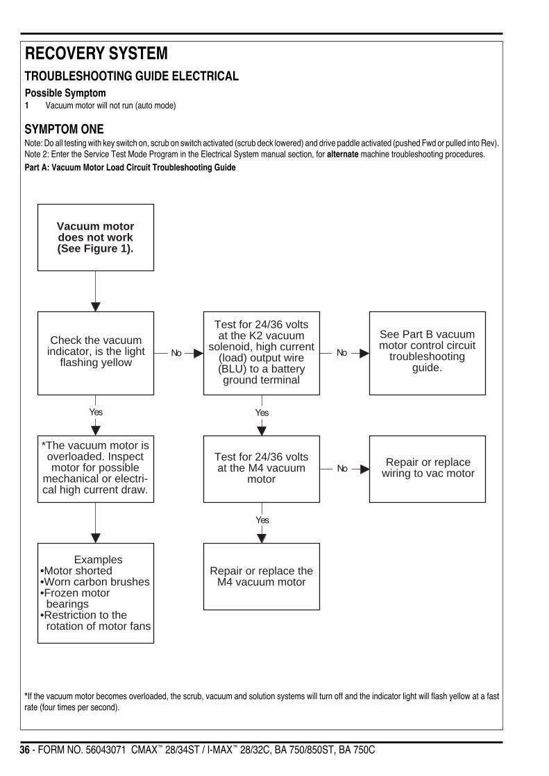
36 - FORM NO. 56043071 CMAX™ 28/34ST / I-MAX™ 28/32C, BA 750/850ST, BA 750C
RECOVERY SYSTEM
Yes
No No
No
Check the vacuumindicator, is the light
flashing yellow
Test for 24/36 voltsat the K2 vacuum
solenoid, high current(load) output wire(BLU) to a batteryground terminal
See Part B vacuummotor control circuit
troubleshootingguide.
Examples•Motor shorted•Worn carbon brushes•Frozen motor bearings•Restriction to the rotation of motor fans
Yes
Test for 24/36 voltsat the M4 vacuum
motor
Repair or replace theM4 vacuum motor
Vacuum motordoes not work(See Figure 1).
Yes
Repair or replacewiring to vac motor
*The vacuum motor isoverloaded. Inspectmotor for possible
mechanical or electri-cal high current draw.
*If the vacuum motor becomes overloaded, the scrub, vacuum and solution systems will turn off and the indicator light will flash yellow at a fastrate (four times per second).
TROUBLESHOOTING GUIDE ELECTRICALPossible Symptom1 Vacuum motor will not run (auto mode)
SYMPTOM ONENote: Do all testing with key switch on, scrub on switch activated (scrub deck lowered) and drive paddle activated (pushed Fwd or pulled into Rev).Note 2: Enter the Service Test Mode Program in the Electrical System manual section, for alternate machine troubleshooting procedures.Part A: Vacuum Motor Load Circuit Troubleshooting Guide
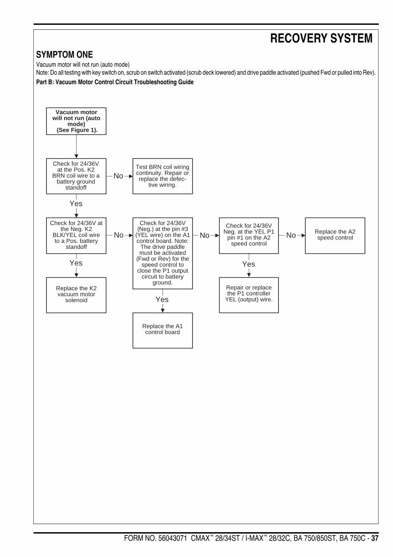
FORM NO. 56043071 CMAX™ 28/34ST / I-MAX™ 28/32C, BA 750/850ST, BA 750C - 37
RECOVERY SYSTEMSYMPTOM ONEVacuum motor will not run (auto mode)Note: Do all testing with key switch on, scrub on switch activated (scrub deck lowered) and drive paddle activated (pushed Fwd or pulled into Rev).Part B: Vacuum Motor Control Circuit Troubleshooting Guide
Vacuum motorwill not run (auto
mode) (See Figure 1).
Replace the K2vacuum motor
solenoid
Check for 24/36Vat the Pos. K2
BRN coil wire to abattery ground
standoff
Check for 24/36V(Neg.) at the pin #3
(YEL wire) on the A1control board. Note:
The drive paddlemust be activated
(Fwd or Rev) for thespeed control to
close the P1 outputcircuit to battery
ground.
Test BRN coil wiringcontinuity. Repair orreplace the defec-
tive wiring.
Yes
No
Check for 24/36V atthe Neg. K2
BLK/YEL coil wireto a Pos. battery
standoff
No No
Yes
Yes
No
Check for 24/36VNeg. at the YEL P1
pin #1 on the A2speed control
Replace the A2speed control
Repair or replacethe P1 controller
YEL (output) wire.
Replace the A1control board
Yes

38 - FORM NO. 56043071 CMAX™ 28/34ST / I-MAX™ 28/32C, BA 750/850ST, BA 750C
RECOVERY SYSTEMMAINTENANCE OF FLOAT CAGE AND FLOAT DUCT1 See Figure 3. Open the recovery tank dome lid and lay it to the side, remove the two (A) Screws and pull the Float Duct (B) and float cage
assembly (C) from vac motor spacer (D).2 Snap apart the two float cage halves (C) and flush clean the float ball and cage pieces.3 Inspect the Gasket (E) and clean any debris from the inside of the float duct housing. Then re-install all parts in reverse order.
VACUUM MOTOR REMOVAL1 Drain the recovery tank using the drain hose.2 Swing open the recovery tank, secure with prop rod and disconnect the vacuum motor harness connector.3 See Figure 3. Remove the vacuum motor Duct Cover (F) secured to the bottom of the recovery tank (qty 4 screws).4 Loosen the exhaust hose clamp and remove Hose (G) from the vac motor discharge tube and completely remove the motor from its mount
cavity.5 Inspect the condition of the vac motor Gasket (H) inside the vac motor mount cavity.6 Make service repairs to the vac motor and re-install by following steps in reverse order.
RECOVERY TANK REMOVAL1 Follow steps 1-4 in the Vacuum Motor Removal section.2 See Figure 3. Remove the Screw (I) and release the Tank Support Bar (J) and allow the tank to swing down to the side of the battery
compartment box.3 Loosen the hose clamp for the tank Drain Hose (K) and pull the hose free.4 Remove the Squeegee Hose (L) from the tank connection.5 Support the tank and remove the (4) screws from the hinge that attaches the tank to the top of the solution tank edge and pull the tank free
from the machine.

FORM NO. 56043071 CMAX™ 28/34ST / I-MAX™ 28/32C, BA 750/850ST, BA 750C - 39
RECOVERY SYSTEM
FRONT
A
B
E
K
L
J
I
F
H
DG
C
FIGURE 3
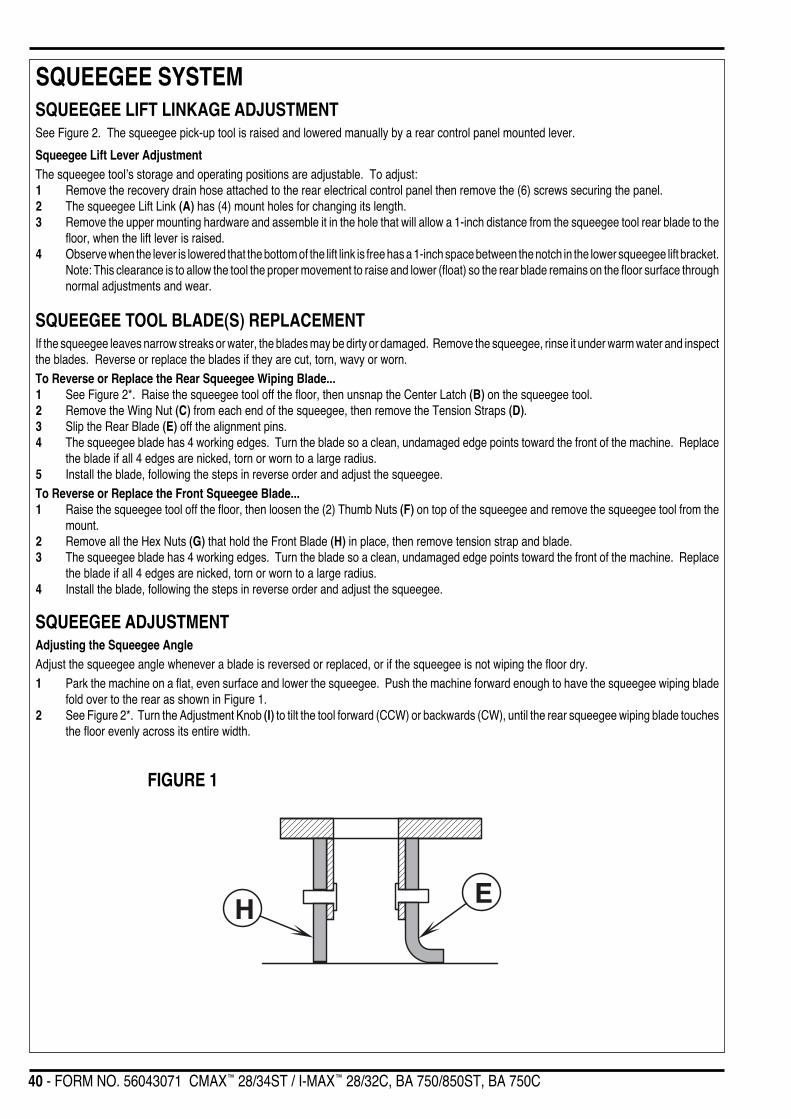
40 - FORM NO. 56043071 CMAX™ 28/34ST / I-MAX™ 28/32C, BA 750/850ST, BA 750C
SQUEEGEE SYSTEMSQUEEGEE LIFT LINKAGE ADJUSTMENTSee Figure 2. The squeegee pick-up tool is raised and lowered manually by a rear control panel mounted lever.
Squeegee Lift Lever AdjustmentThe squeegee tool’s storage and operating positions are adjustable. To adjust:1 Remove the recovery drain hose attached to the rear electrical control panel then remove the (6) screws securing the panel.2 The squeegee Lift Link (A) has (4) mount holes for changing its length.3 Remove the upper mounting hardware and assemble it in the hole that will allow a 1-inch distance from the squeegee tool rear blade to the
floor, when the lift lever is raised.4 Observe when the lever is lowered that the bottom of the lift link is free has a 1-inch space between the notch in the lower squeegee lift bracket.
Note: This clearance is to allow the tool the proper movement to raise and lower (float) so the rear blade remains on the floor surface throughnormal adjustments and wear.
SQUEEGEE TOOL BLADE(S) REPLACEMENTIf the squeegee leaves narrow streaks or water, the blades may be dirty or damaged. Remove the squeegee, rinse it under warm water and inspectthe blades. Reverse or replace the blades if they are cut, torn, wavy or worn.To Reverse or Replace the Rear Squeegee Wiping Blade...1 See Figure 2*. Raise the squeegee tool off the floor, then unsnap the Center Latch (B) on the squeegee tool.2 Remove the Wing Nut (C) from each end of the squeegee, then remove the Tension Straps (D).3 Slip the Rear Blade (E) off the alignment pins.4 The squeegee blade has 4 working edges. Turn the blade so a clean, undamaged edge points toward the front of the machine. Replace
the blade if all 4 edges are nicked, torn or worn to a large radius.5 Install the blade, following the steps in reverse order and adjust the squeegee.To Reverse or Replace the Front Squeegee Blade...1 Raise the squeegee tool off the floor, then loosen the (2) Thumb Nuts (F) on top of the squeegee and remove the squeegee tool from the
mount.2 Remove all the Hex Nuts (G) that hold the Front Blade (H) in place, then remove tension strap and blade.3 The squeegee blade has 4 working edges. Turn the blade so a clean, undamaged edge points toward the front of the machine. Replace
the blade if all 4 edges are nicked, torn or worn to a large radius.4 Install the blade, following the steps in reverse order and adjust the squeegee.
SQUEEGEE ADJUSTMENTAdjusting the Squeegee AngleAdjust the squeegee angle whenever a blade is reversed or replaced, or if the squeegee is not wiping the floor dry.1 Park the machine on a flat, even surface and lower the squeegee. Push the machine forward enough to have the squeegee wiping blade
fold over to the rear as shown in Figure 1.2 See Figure 2*. Turn the Adjustment Knob (I) to tilt the tool forward (CCW) or backwards (CW), until the rear squeegee wiping blade touches
the floor evenly across its entire width.
FIGURE 1
H E

FORM NO. 56043071 CMAX™ 28/34ST / I-MAX™ 28/32C, BA 750/850ST, BA 750C - 41
SQUEEGEE SYSTEM
FRONT
A
I
C
F
G
H
E
C B
D
D
FIGURE 2
*Note: Figure 2 shows the squeegee tool for the CMAX™ 28ST, I-MAX™ 28C, BA 750ST, and BA 750C, the squeegee tool for the CMAX™ 34ST,I-MAX™ 32C, and BA 850ST are similar in adjustment and blade replacement.
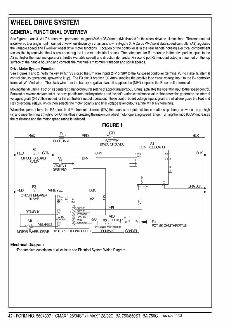
42 - FORM NO. 56043071 CMAX™ 28/34ST / I-MAX™ 28/32C, BA 750/850ST, BA 750C
WHEEL DRIVE SYSTEM
REDFUSE, 150A
F11 2 RED
BT1+ -
BATTERY24VDC OR 36VDC
BLK
BLK
A1CONTROL BOARD
RED GRNF2
1 2
CIRCUIT BREAKER5 AMP
S3
SWITCHSPST KEY
GRN
GRA/BLK
4
13
B-2
B-3
14 B+21 B+1
BRN 567
11
12
FOR
/REV
B-1
298310
BLKREDF3
1 2
CIRCUIT BREAKER30 AMP
WHT/YEL
BRN
YEL
YEL
R1POT. 5K OHM THROTTLE
A2
1208 SPEED CONTROLLER
M1
MMOTOR, WHEEL DRIVE
+-
BRN/BLK
YEL/RED
B-(T2)
B+(T1)
B+B-
P2
(T3)M1
(T4)M2
+ WHENFORWARD
P1
12
123456
OUTPUTOUTPUTKEYSWITCHREVERSEWIPERFORWARD
+-
VIO
BRN/WHT GRN/YEL
1
3
2
POT. 25K OHM SPEED LIMIT
1
223 1
RED/BLKGRA R2
GENERAL FUNCTIONAL OVERVIEWSee Figures 1 and 3. A 1/2 horsepower permanent magnet (24V or 36V) motor (M1) is used for the wheel drive on all machines. The motor outputis delivered to a single front mounted drive wheel driven by a chain as shown in Figure 3. A Curtis PMC solid state speed controller (A2) regulatesthe variable speed and Fwd/Rev wheel drive motor functions. Location of the controller is in the rear handle housing electrical compartment(accessible by removing the 4 screws securing the large rear electrical panel). The potentiometer R1 mounted in the drive paddle inputs to theA2 controller the machine operator’s throttle (variable speed) and direction demands. A second pot R2 (knob adjusted) is mounted on the topsurface of the handle housing and controls the machine’s maximum transport and scrub speeds.
Drive Motor System FunctionSee Figures 1 and 2. With the key switch S3 closed the Brn wire inputs 24V or 36V to the A2 speed controller (terminal #3) to make its internalcontrol circuits operational (powering it up). The F3 circuit breaker (30 Amp) supplies the positive load circuit voltage input to the B+ controllerterminal (Wht/Yel wire). The black wire from the battery negative standoff supplies the (NEG.) input to the B- controller terminal.
Moving the 5K Ohm R1 pot off its centered balanced neutral setting of approximately 2500 Ohms, activates the operator input to the speed control.Forward or reverse movement of the drive paddle rotates the pot shaft and the pot’s variable resistance value changes which generates the internalvoltage signals (0-5Volts) needed for the controller’s output operation. These control board voltage input signals are what energizes the Fwd andRev directional relays, which then selects the motor polarity and final voltage level outputs at the M1 & M2 terminals.
When the operator turns the R2 speed limit Pot from min. to max. (CW) this causes an input resistance relationship change between the pot high(+) and wiper terminals (high to low Ohms) thus increasing the maximum wheel motor operating speed range. Turning the knob (CCW) increasesthe resistance and the motor speed range is reduced.
FIGURE 1
Electrical Diagram*For complete description of all callouts see Electrical System Wiring Diagram.
revised 11/02
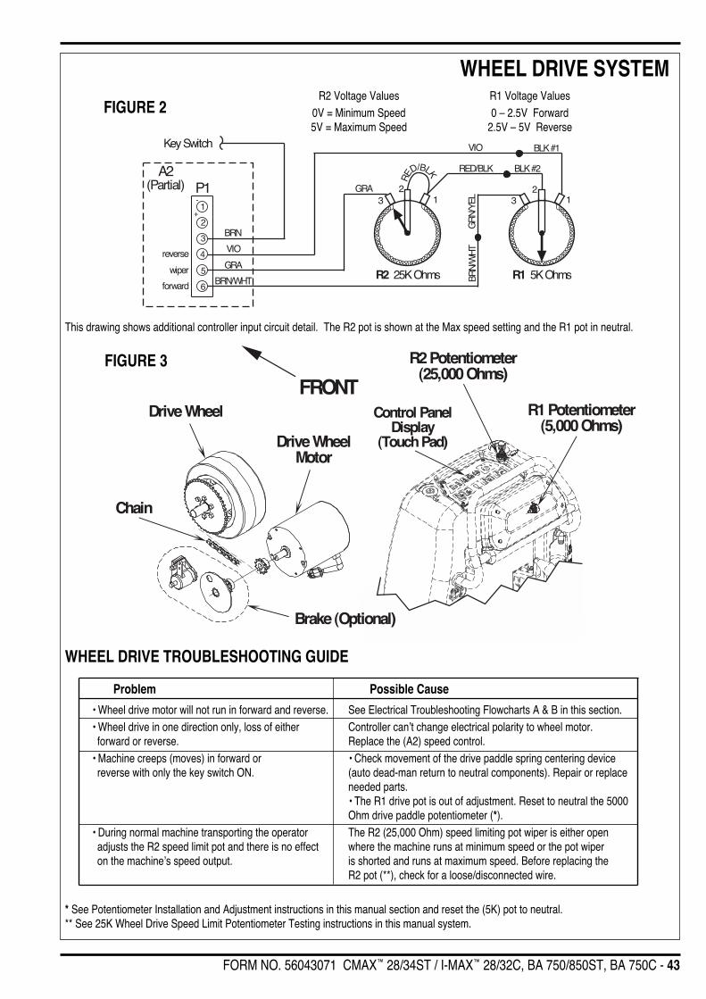
FORM NO. 56043071 CMAX™ 28/34ST / I-MAX™ 28/32C, BA 750/850ST, BA 750C - 43
WHEEL DRIVE SYSTEM
-
+1
2
3
4
5
6
RE
D/BLKA2(Partial)
BRN
VIO
GRA
BRN/
WH
TG
RN/
YEL
BRN/WHT
21
VIO
P1
Key Switch
R2 25K Ohms R1 5K Ohms
3
BLK #1
BLK #2RED/BLK
GRA
reverse
wiper
forward
213
FRONT
Chain
Drive Wheel
Drive WheelMotor
R2 Potentiometer(25,000 Ohms)
R1 Potentiometer(5,000 Ohms)
Brake (Optional)
Control PanelDisplay
(Touch Pad)
WHEEL DRIVE TROUBLESHOOTING GUIDE
Problem Possible Cause
• Wheel drive motor will not run in forward and reverse. See Electrical Troubleshooting Flowcharts A & B in this section.• Wheel drive in one direction only, loss of either Controller can’t change electrical polarity to wheel motor. forward or reverse. Replace the (A2) speed control.• Machine creeps (moves) in forward or • Check movement of the drive paddle spring centering device reverse with only the key switch ON. (auto dead-man return to neutral components). Repair or replace
needed parts.• The R1 drive pot is out of adjustment. Reset to neutral the 5000Ohm drive paddle potentiometer (*).
• During normal machine transporting the operator The R2 (25,000 Ohm) speed limiting pot wiper is either open adjusts the R2 speed limit pot and there is no effect where the machine runs at minimum speed or the pot wiper on the machine’s speed output. is shorted and runs at maximum speed. Before replacing the
R2 pot (**), check for a loose/disconnected wire.
* See Potentiometer Installation and Adjustment instructions in this manual section and reset the (5K) pot to neutral.** See 25K Wheel Drive Speed Limit Potentiometer Testing instructions in this manual system.
FIGURE 3
FIGURE 2R2 Voltage Values R1 Voltage Values
0V = Minimum Speed 0 – 2.5V Forward5V = Maximum Speed 2.5V – 5V Reverse
This drawing shows additional controller input circuit detail. The R2 pot is shown at the Max speed setting and the R1 pot in neutral.
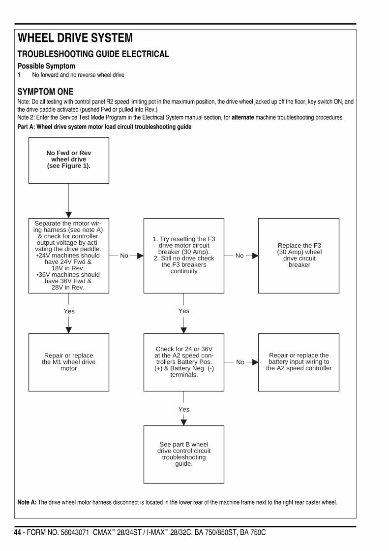
44 - FORM NO. 56043071 CMAX™ 28/34ST / I-MAX™ 28/32C, BA 750/850ST, BA 750C
WHEEL DRIVE SYSTEM
No Fwd or Revwheel drive
(see Figure 1).
1. Try resetting the F3drive motor circuitbreaker (30 Amp).
2. Still no drive checkthe F3 breakers
continuity
Replace the F3(30 Amp) wheel
drive circuitbreaker
No
Check for 24 or 36Vat the A2 speed con-trollers Battery Pos.
(+) & Battery Neg. (-)terminals.
Repair or replace thebattery input wiring to
the A2 speed controller
Separate the motor wir-ing harness (see note A)
& check for controlleroutput voltage by acti-
vating the drive paddle.•24V machines should
have 24V Fwd &18V in Rev.
•36V machines shouldhave 36V Fwd &
28V in Rev.
Repair or replacethe M1 wheel drive
motor
Yes
See part B wheeldrive control circuit
troubleshootingguide.
No
Yes
No
Yes
TROUBLESHOOTING GUIDE ELECTRICALPossible Symptom1 No forward and no reverse wheel drive
SYMPTOM ONENote: Do all testing with control panel R2 speed limiting pot in the maximum position, the drive wheel jacked up off the floor, key switch ON, andthe drive paddle activated (pushed Fwd or pulled into Rev.)Note 2: Enter the Service Test Mode Program in the Electrical System manual section, for alternate machine troubleshooting procedures.Part A: Wheel drive system motor load circuit troubleshooting guide
Note A: The drive wheel motor harness disconnect is located in the lower rear of the machine frame next to the right rear caster wheel.

FORM NO. 56043071 CMAX™ 28/34ST / I-MAX™ 28/32C, BA 750/850ST, BA 750C - 45
WHEEL DRIVE SYSTEM
No Fwd or Rev wheeldrive (see Figure 1).
At the A2 speed controllercheck for 24/36V input, Brn
wire to Negative batterystandoff
Repair or replace theBrn control circuit
input wire.
Check the total resistance of thedrive paddle R1 pot. Remove wiresand measure across the two out-side terminals, should read 4500-
5500 Ohms.
Test shows an open(infinity) replace the R1potentiometer with P.N.
56397029
Check the total resistance ofthe speed limit R2 pot. Removewires and measure across thetwo outside terminals, should
read approximately 25000Ohms.
Separate the motor wiring harnessdisconnect (see Note B) & check
for controller output voltage by acti-vating the drive paddle.
•24V machines should have 24V inFwd & 18V in Rev.
•36V machines should have 36V inFwd & 28V in Rev.
Test shows an open(infinity) replace the R2potentiometer with P.N.
56397123
Replace the A2speed controller
Check the functional operation ofthe wiper resistance circuits (seeNote A) for both the 5K(R1) pot &
the 25K(R2) pot.Test measurements should show avariable resistance within spec. foreach individual pot when the potshaft is turned in both directions.
Replace the specifiedpot(s) that's measure-ments show an open
circuit.
Yes
Yes
Yes
Yes
No
No
No
No
No
SYMPTOM ONENote: Do all testing with control panel R2 speed limiting pot in the maximum position, the drive wheel jacked up off the floor, key switch ON, andthe drive paddle activated (pushed Fwd or pulled into Rev.)Part B: Wheel drive system motor control circuit troubleshooting guide
Note A: Follow the potentiometer test instructions shown in the Wheel Drive System.Note B: The drive wheel motor harness disconnect is located in the lower rear of the machine frame next to the right rear caster wheel.
TROUBLESHOOTING GUIDE ELECTRICAL (CONTINUED)

46 - FORM NO. 56043071 CMAX™ 28/34ST / I-MAX™ 28/32C, BA 750/850ST, BA 750C
WHEEL DRIVE SYSTEM
I
FRONT
J
H
GC
B
A
D
AE
F
EMotor Sprocket ifoptional brake is
installed
FIGURE 4

FORM NO. 56043071 CMAX™ 28/34ST / I-MAX™ 28/32C, BA 750/850ST, BA 750C - 47
WHEEL DRIVE SYSTEMDRIVE MOTOR REMOVAL (ALL MODELS)
WARNING!Disconnect the battery pack before servicing machine.
1 Remove the left side chassis panel to access the drive motor.2 Disconnect the drive motor wiring connector.3 See Figure 4. Loosen the (3) Motor Mount Bolts (A) then loosen the Lock Nut (B) and back out Adjustment Bolt (C) several turns to loosen
the drive chain tension.4 Remove the retainer clip from the chain’s master link then separate and remove the chain from the sprockets.5 Loosen both the Set Screws (D) from the drive motor Sprocket (E) then pull the sprocket off the motor shaft. Note use a 1/8" Hex socket
to loosen the set screws.6 Support the Drive Motor, remove the (3) Motor Mount Bolts (A) then remove the motor and the chain tensioner Bracket (G) from the machine.7 Follow steps 1-6 in reverse order to reassemble, then refer to the chain adjustment section to retention the chain. Note: Make sure drive
motor Sprocket (E) and the drive wheel sprocket are in alignment.
DRIVE WHEEL REMOVAL (CYLINDRICAL)
WARNING!Disconnect the battery pack connector before servicing machine.
WARNING!Never work under machine without safety stands or blocking to support the machine.
1 Drain both the solution and recovery tanks. Next remove the scrub deck debris hopper and have the scrub deck in the up (stored) positionwith the scrub brushes installed.
2 Place wood blocking in front and rear of both caster wheels to prevent the machine from rolling.3 Remove the left and right side chassis panels and then remove the drive chain (follow instructions in the Chain Removal and Chain
Adjustment section).4 See Figure 4. Remove the two hardware items (H & I) from both front Axle Clamps (J) then loosen the two rear screws and nuts and swing
the clamps to the rear.5 Next shim the bottom of the brush deck housing in the middle (front to back) with wood blocking. Use blocking with approximate dimensions
3-1/2" wide, 2-1/4" thick and 15" long (9cm x 5.7cm x 38cm). Note: A standard 2x4 and 1x4 stacked on top of each other (together) will matchthe proper thickness (height) needed.
6 Next read the instructions for using the Service Test Mode steps 1-5 located in the electrical system manual section. Then enter the maincontroller diagnostic Service Test Mode.
7 See the Know Your Machine section control panel drawing. When in the service test mode press the Scrub On/Pressure Increase Button(G). This switch circuit is used to control the output to the scrub deck lift actuator. Pressing and releasing this switch will cycle the actuatoroutput, Up/Down and ON/OFF.
8 Activate the Switch (G) turning on the actuator where it runs to its down position and stops, then turn the key switch off and disconnect thebatteries. This operating of the lift motor will raise the frame off the floor creating the needed clearance to remove the drive wheel. Roll thewheel forward then maneuver the wheel assembly out from the right side of the machine.
CAUTION!When in the Service Test Mode don’t press (activate) the Scrub Off/Pressure Decrease Switch (H) when the wood blocking ispositioned under the scrub brushes as it will turn on the brush motors.
9 Make needed service repairs and re-install the drive wheel following the above steps in reverse order. Note: You must re-enter the ServiceTest Mode to raise the scrub deck up away from the floor.
10 Test-drive the machine for proper operation.
Important Service Notes: Listed below are alternate lifting methods that can be used to raise and lower the chassis to remove the drive wheel.• Jack (raise) front of machine to where the drive wheel axle is able to clear the top wheel mount clamp bracket. Service Tip: Place a small
hydraulic bottle jack or mechanical scissors jack underneath the front of the scrub deck in the middle.• Shown in the Electrical System is the actuator power cord adapter PN 56407502 and instructions for use. This tool can be attached to the
lift actuator (connector) for special output control to raise and lower the chassis with the placement of the above described wood blocking.
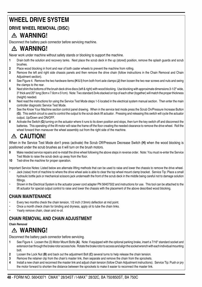
48 - FORM NO. 56043071 CMAX™ 28/34ST / I-MAX™ 28/32C, BA 750/850ST, BA 750C
WHEEL DRIVE SYSTEMDRIVE WHEEL REMOVAL (DISC)
WARNING!Disconnect the battery pack connector before servicing machine.
WARNING!Never work under machine without safety stands or blocking to support the machine.1 Drain both the solution and recovery tanks. Next place the scrub deck in the up (stored) position, remove the splash guards and scrub
brushes.2 Place wood blocking in front and rear of both caster wheels to prevent the machine from rolling.3 Remove the left and right side chassis panels and then remove the drive chain (follow instructions in the Chain Removal and Chain
Adjustment section).4 See Figure 4. Remove the two hardware items (H & I) from both front axle clamps (J) then loosen the two rear screws and nuts and swing
the clamps to the rear.5 Next shim the bottoms of the brush deck drive discs (left & right) with wood blocking. Use blocking with approximate dimensions 3-1/2" wide,
3" thick and 20" long (9cm x 7.6cm x 51cm). Note: Two standard 2x4s stacked on top of each other (together) will match the proper thickness(height) needed.
6 Next read the instructions for using the Service Test Mode steps 1-5 located in the electrical system manual section. Then enter the maincontroller diagnostic Service Test Mode.
7 See the Know Your Machine section control panel drawing. When in the service test mode press the Scrub On/Pressure Increase Button(G). This switch circuit is used to control the output to the scrub deck lift actuator. Pressing and releasing this switch will cycle the actuatoroutput, Up/Down and ON/OFF.
8 Activate the Switch (G) turning on the actuator where it runs to its down position and stops, then turn the key switch off and disconnect thebatteries. This operating of the lift motor will raise the frame off the floor creating the needed clearance to remove the drive wheel. Roll thewheel forward then maneuver the wheel assembly out from the right side of the machine.
CAUTION!When in the Service Test Mode don’t press (activate) the Scrub Off/Pressure Decrease Switch (H) when the wood blocking ispositioned under the scrub brushes as it will turn on the brush motors.9 Make needed service repairs and re-install the drive wheel following the above steps in reverse order. Note: You must re-enter the Service
Test Mode to raise the scrub deck up away from the floor.10 Test-drive the machine for proper operation.
Important Service Notes: Listed below are alternate lifting methods that can be used to raise and lower the chassis to remove the drive wheel.• Jack (raise) front of machine to where the drive wheel axle is able to clear the top wheel mount clamp bracket. Service Tip: Place a small
hydraulic bottle jack or mechanical scissors jack underneath the front of the scrub deck in the middle being careful not to damage solutionfittings.
• Shown in the Electrical System is the actuator power cord adapter PN 56407502 and instructions for use. This tool can be attached to thelift actuator for special output control to raise and lower the chassis with the placement of the above described wood blocking.
CHAIN MAINTENANCE• Every two months check the chain tension, 1/2 inch (13mm) deflection at mid point.• Once a month check chain for binding and dryness, apply oil to lube the chain links.• Yearly remove chain, clean and re-oil.
CHAIN REMOVAL AND CHAIN ADJUSTMENTChain Removal
WARNING!Disconnect the battery pack connector before servicing.1 See Figure 4. Loosen the (3) Motor Mount Bolts (A). Note: If equipped with the optional parking brake, insert a 7/16" standard socket and
extension bar through the brake rotor access hole. Rotate the brake rotor to access and align the socket wrench with each individual mountingbolt.
2 Loosen the Lock Nut (B) and back out the adjustment Bolt (C) several turns to help release the chain tension.3 Remove the retainer clip from the chain’s master link, then separate and remove the chain from the sprockets.4 Install a new chain and reconnect the master link and adjust chain tension (follow Chain Adjustment instructions). Service Tip: Push or pry
the motor forward to shorten the distance between the sprockets to make it easier to reconnect the master link.

FORM NO. 56043071 CMAX™ 28/34ST / I-MAX™ 28/32C, BA 750/850ST, BA 750C - 49
WHEEL DRIVE SYSTEM
K
L
Chain Adjustment
1 Loosen the (3) Motor Mount Bolts (A) and the adjustment Lock Nut (B) to adjust chain tension.2 Turn the adjustment Bolt (C) in (CW) to obtain a 1/2" (13mm) chain deflection between the sprockets when moderate pressure is applied
to the chain.3 Retighten the adjustment bolt lock nut, the (3) motor mount bolts and test the drive system for proper operation.
OPTIONAL PARKING BRAKE OPERATION1 See Figure 5. To set the parking brake press the center of the brake assembly handle and at the same time grip the outside knob then pull
backwards and release.2 Next turn the knob CCW to tighten the cable for a firm brake caliper to rotor engagement.3 To release the parking brake, press the end of the handle and push in.
OPTIONAL BRAKE - ASSEMBLY REMOVAL
WARNING!Disconnect the battery pack before servicing the machine.
1 Remove the left side chassis panel to access the parking brake components.2 Remove the bolt and nut that secure the brake cable at the brake caliper arm.3 Separate the drive chain by removing the master link.4 See Figure 4. Rotate the brake rotor/sprocket assembly (E) to a working position to access the (2) 1/4-20 set screws. Loosen both the Set
Screws (D) using a 1/8" Hex socket then pull the caliper and rotor assembly off the end of the drive motor shaft.5 Follow the above steps in reverse order to reassemble. Note: Make sure the drive brake rotor/drive sprocket and drive wheel sprocket are
in alignment to prevent binding and excessive wear.
FIGURE 5
Brake RotorDrive MotorSprocket
Drive WheelSprocket
Chain
Front DriveWheel
FRONT
OPTIONAL BRAKE - CALIPER ADJUSTMENT
FIGURE 6
FIGURE 7
1 See Figure 7. Loosen the large outer Nut (K), thenturn the inner caliper adjustment Screw (L) in tocompensate for pad wear. Note: Do not over adjustto the point that the pad drags excessively against thebrake rotor. After making the adjustment test theparking brake for proper operation both set andreleased.
CHAIN REMOVAL AND CHAIN ADJUSTMENT (CONTINUED)
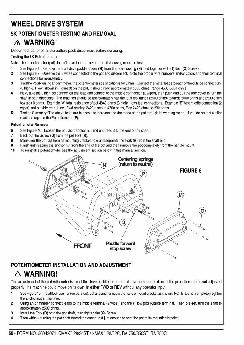
50 - FORM NO. 56043071 CMAX™ 28/34ST / I-MAX™ 28/32C, BA 750/850ST, BA 750C
WHEEL DRIVE SYSTEM
FRONT
N
P
M
O
Q
R
Paddle forwardstop screw
Centering springs(return to neutral)
5K POTENTIOMETER TESTING AND REMOVAL
WARNING!Disconnect batteries at the battery pack disconnect before servicing.Testing the 5K PotentiometerNote: The potentiometer (pot) doesn’t have to be removed from its housing mount to test.1 See Figure 8. Remove the front drive paddle Cover (M) from the rear housing (N) held together with (4) item (O) Screws.2 See Figure 9. Observe the 3 wires connected to the pot and disconnect. Note the proper wire numbers and/or colors and their terminal
connections for re-assembly.3 Test the Pot (P) using an ohmmeter, the potentiometer specification is 5K Ohms. Connect the meter leads to each of the outside connections
(3 high & 1 low, shown in Figure 9) on the pot, it should read approximately 5000 ohms (range 4500-5500 ohms).4 Next, take the 3 high pot connection test lead and connect to the middle connection (2 wiper), then push and pull the rear cover to turn the
shaft in both directions. The readings should be approximately half the total resistance (2500 ohms) towards 5000 ohms and 2500 ohmstowards 0 ohms. Example “A” total resistance of pot 4840 ohms (3 high/1 low) test connections. Example “B” test middle connection (2wiper) and outside rear (1 low) Fwd reading 2420 ohms to 4700 ohms, Rev 2420 ohms to 230 ohms.
5 Testing Summary: The above tests are to show the increase and decrease of the pot through its working range. If you do not get similarreadings replace the Potentiometer (P).
Potentiometer Removal6 See Figure 10. Loosen the pot shaft anchor nut and unthread it to the end of the shaft.7 Back out the Screw (Q) from the pot Fork (R).8 Maneuver the pot out from its mounting bracket hole and separate the Fork (R) from the shaft end.9 Finish unthreading the anchor nut from the end of the pot and then remove the pot completely from the handle mount.10 To reinstall a potentiometer see the adjustment section below in this manual section.
POTENTIOMETER INSTALLATION AND ADJUSTMENT
WARNING!The adjustment of the potentiometer is to set the drive paddle for a neutral drive motor operation. If the potentiometer is not adjustedproperly, the machine could move on its own, in either FWD or REV without any operator input.1 See Figure 10. Install lock washer (on pot side), pot and anchor nut to the handle mount bracket as shown. NOTE: Do not completely tighten
the anchor nut at this time.2 Using an ohmmeter connect leads to the middle terminal (2 wiper) and the (1 low pot) outside terminal. Then pre-set, turn the shaft to
approximately 2500 ohms.3 Install the Fork (R) onto the pot shaft, then tighten the (Q) Screw.4 Then without turning the pot shaft thread the anchor nut just enough to seat the pot to its mounting bracket.
FIGURE 8
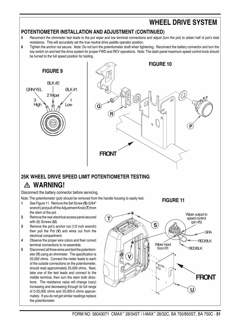
FORM NO. 56043071 CMAX™ 28/34ST / I-MAX™ 28/32C, BA 750/850ST, BA 750C - 51
WHEEL DRIVE SYSTEM
GRA
RED/BLK
RED/BLK
Wiper output tospeed control
(pin #5)
Wiper inputfrom R1
ST
V
FRONT
U
Q
FRONT
R
P
BLK #1
BLK #2
GRN/YEL
3High
1Low
2 Wiper
5 Reconnect the ohmmeter test leads to the pot wiper and low terminal connections and adjust (turn the pot) to obtain half of pot’s totalresistance. This will accurately set the true neutral drive paddle operator position.
6 Tighten the anchor nut secure. Note: Do not turn the potentiometer shaft when tightening. Reconnect the battery connector and turn thekey switch on and test the drive system for proper FWD and REV operations. Note: The dash panel maximum speed control knob shouldbe turned to the full speed position for testing.
25K WHEEL DRIVE SPEED LIMIT POTENTIOMETER TESTING
WARNING!Disconnect the battery connector before servicing.Note: The potentiometer (pot) should be removed from the handle housing to easily test.
FIGURE 9
FIGURE 11
FIGURE 10
POTENTIOMETER INSTALLATION AND ADJUSTMENT (CONTINUED)
1 See Figure 11. Remove the Set Screw (S) (5/64"wrench) and pull off the Adjustment Knob (T) fromthe stem of the pot.
2 Remove the rear electrical access panel securedwith (6) Screws (U).
3 Remove the pot’s anchor nut (1/2 inch wrench)then pull the Pot (V) and wires out from theelectrical compartment.
4 Observe the proper wire colors and their correctterminal connections to re-assemble.
5 Disconnect all three wires and test the potentiom-eter (V) using an ohmmeter. The specification is25,000 ohms. Connect the meter leads to eachof the outside connections on the potentiometer,should read approximately 25,000 ohms. Next,take one of the test leads and connect to themiddle terminal, then turn the stem both direc-tions. The resistance value will change (vary)increasing and decreasing through its full rangeof 0-25,000 ohms and 25,000-0 ohms approxi-mately. If you do not get similar readings replacethe potentiometer.

52 - FORM NO. 56043071 CMAX™ 28/34ST / I-MAX™ 28/32C, BA 750/850ST, BA 750C
ELECTRICAL SYSTEM
(6) MAX 267KG/588lb.
(4) MAX 190KG/420lb.305 AH @20 HR RATE
56016486
56016413
305 AH @20 HR RATE
BATTERY SPECIFICATIONS- Use a combination of multiple 2-volt cell units to construct a 24 or 36 Volt DC battery pack system.- Nilfisk-Advance recommended battery pack capacity is a 238 AH @ 20 Hour Rate deep cycle battery system. Note: The battery pack must fitthe battery compartment size listed in Specifications.
BATTERY CHARGER SPECIFICATIONS- Use a 24 or 36 Volt DC output charger matching the DC battery pack voltage and the input AC line voltage supply being used.- Always when selecting a battery charger follow the recommendation of the battery supplier to match the proper charger DC output amperageto the amp/hour rating batteries being installed. This will prevent the battery pack from being over or under charged.- The recommended 238 AH battery should be matched to a 24V, 25 Amp output charger on machines using (4) batteries and a 36V, 25 Amp chargeron machines using (6) batteries.
INSTALL THE BATTERIES
WARNING!
FIGURE 1
Use extreme caution when working with batteries. Sulfuric acid in batteries can causesevere injury if allowed to contact the skin or eyes. Explosive hydrogen gas is ventedfrom inside the batteries through openings in the battery caps. This gas can be ignitedby any electrical arc, spark or flame.When Servicing Batteries...• Remove all jewelry.• Do not smoke.• Wear chemical goggles, rubber gloves and a protective apron.• Work in a well-ventilated area.• Do not allow tools to touch more than one battery terminal at a time.
CAUTION!Electrical components in this machine can be severely damaged if the batteries are notinstalled and connected properly. Batteries should be installed by Nilfisk-Advance or bya qualified electrician.
1 Remove the batteries from their shipping crate and carefully inspect them for cracks orother damage. If damage is evident, contact the carrier that delivered them or the batterymanufacturer to file a damage claim.
2 Turn the Master Key Switch (B) OFF and remove the key.3 Tip the recovery tank to the side, locked position. Remove the battery cables from inside
the battery compartment.4 Your machine comes from the factory with enough battery cables to install four or six (6
volt), 305 Amp hour batteries. Carefully lift the batteries into the battery compartment andarrange them exactly as shown. Secure the batteries as close to the back of the machineas possible.
5 The terminals on the battery cables are marked “+” for positive and “-“ for negative. Installthe battery cables as shown, with the terminals marked “+” on the positive battery terminalsand the terminals marked “-“ on the negative terminals. Position the cables so the batterycaps can be easily removed for battery service.
6 Carefully tighten the nut in each battery terminal until the terminal will not turn on the batterypost. Then tighten the nut one additional turn. Do not over-tighten the terminals, or they will be very difficult to remove for future service.
7 Coat the terminals and posts with spray-on battery terminal coating (available at most auto parts stores).8 Put one of the black rubber boots over each of the terminals.
DESCRIPTION OF THE BATTERY LOW VOLTAGE CUTOUT FEATUREAll models discussed in this manual are equipped with a low voltage cutout feature to prevent over-discharging of the batteries. When a machine’sbattery pack voltage falls below specifically defined thresholds (voltage settings) the scrub system is automatically shut down. The cutout levelis adjustable. The standard lead acid battery (wet cell) setting is 1.72V per cell and alternate maintenance free battery (gel cell) setting is 1.81Vper cell. The standard setting is factory selected and should be used unless the battery manufacturer specifies the higher cutout voltage.Special Service Note: On all the 24V & 36V machines a minimum recharge voltage of 2.09 volts per cell must be reached to allow the scrub brushand solution system to (reset) function again. A 24V-battery pack must increase to a 25.1-volt minimum and a 36V battery pack to 37.6 volts.

FORM NO. 56043071 CMAX™ 28/34ST / I-MAX 28/32C, BA 750/850ST, BA 750C - 53
ELECTRICAL SYSTEMDESCRIPTION OF THE BATTERY CONDITION INDICATORSThe Battery Condition Indicator (J) will give an indication of the state of charge of the batteries. The battery condition indicator will retain the state-of-charge evenif the key has been turned off. The state-of-charge indication is reset to full charge when the batteries have been recharged. It is also possible to choose betweentwo different low voltage thresholds depending on whether maintenance free or standard batteries are being used (have qualified service engineer performthis selection*). NOTE: The following percentages are based on useable battery capacity not total battery capacity. Therefore, 100% discharge = 80% of totalbattery capacity for standard wet cell batteries or 70% of total battery capacity for maintenance free batteries.
Explanation of Battery Indicator Lights and Voltage Ranges
36 volt machines 24 volt machines% of
Battery Indicator Discharge Standard Alternate Standard Alternate
Green Full to 50% 34.0+ 34.5+ 22.6+ 23.0+
Green & Yellow 50% to 75% 33.0-34.0 34.0-34.5 22.0-22.6 22.6-23.0
Yellow 75% to 90% 32.0-33.0 33.5-34.0 21.3-22.0 22.3-22.6
Yellow & Red 90% to 95% 31.5-32.0 33.0-33.5 21.0-21.3 22.0-22.3
Red 95% to 99% 31.0-31.5 32.5-33.0 20.6-21.0 21.6-22.0
Flashing Red/Cutoff 100% <31.0 <32.5 <20.6 <21.6
*Important Note: See the Main Control Board Special Program Options manual section (located in the Electrical System) and follow the instructions for changingthe low voltage cutout threshold.
CHARGING THE BATTERIESCharge the machine’s battery pack each time the machine is used, or when the Battery Condition Indicator (J) is showing red flashing indicatorlights. Note: The machine also uses a special low voltage cutout that inhibits the scrub system see in this manual section the description for thelow voltage cutout feature.To Charge the Batteries...1 Drain the recovery tank, next lift open the hinged tank setting the prop rod. Locate the machine/battery pack connector assembly (9).2 Pull up (separate) the top removable battery pack connector half then push together both the battery charger and battery pack connectors.3 Follow the instructions on the battery charger.4 Check the fluid level in all the battery cells after charging the batteries. Add distilled water, if necessary, to bring the fluid level up to the
bottom of each battery cells filler tubes.
WARNING!Do not fill the batteries before charging. Only charge batteries in a well-ventilated area. Do not smoke while servicing the batteries.
BATTERY MAINTENANCEProper maintenance of electric vehicle batteries can greatly extend their life. Well-maintained batteries may last up to 3 years, but failure after1 year is common if maintenance has been poor.There are 3 simple rules for good battery maintenance:• Maintain Proper Electrolyte Level (Weekly) - Use distilled water in batteries whenever possible. If batteries are discharged, add just
enough water to cover the plates in each cell. If batteries are fully charged, fill each cell to the bottom of the filler tube. Do not over-fill thebatteries! Do not add acid to batteries!
• Keep the Batteries Charged (Weekly) - Batteries should be charged each time that a machine is used for more than 1 hour. Machineoperators should open the battery compartment cover for charging, to avoid a concentrated build-up of hydrogen gas. Operators shouldfollow the instructions provided with their specific battery charger, to determine how long the batteries should be charged. Even when amachine is stored, the batteries should be charged once a month to prevent the batteries from “sulfating”. Almost all battery caps are vented,so there’s no need to loosen or remove them for charging.
• Keep the Batteries Clean (Monthly) - Use a damp cloth to wipe dirt from the top of the batteries. Battery terminals must be clean and tight.If the tops of the batteries are wet after charging, the batteries have probably been over-filled or over-charged. Note: If there is acid on thebatteries, wash the tops of the batteries with a solution of baking soda and water (2) tablespoons of baking soda to 1 quart of water.

54 - FORM NO. 56043071 CMAX™ 28/34ST / I-MAX™ 28/32C, BA 750/850ST, BA 750C
ELECTRICAL SYSTEMBATTERY TESTINGA battery problem is usually recognized by the machine operator, as a decrease in the machine’s running time. This condition is usually causedby one or more “dead cells” in the battery system- that is, one or more cells that is putting out less voltage than the other cells.Note: Always charge batteries before testing.There are 2 ways to find a dead cell:• Use a hydrometer to check the specific gravity (or “state of charge”) of the fluid in each cell. A dead cell is one that reads 50 points (or more)
lower than the other cells.• Use a volt meter to check the voltage of each battery with the scrub and drive motors running. The battery with the dead cell will read 1 or
2 volts lower than the other batteries in the system.If the batteries in the machine are more than 1 year old, it’s usually best to replace the whole set, rather than replacing just one battery.
ACTUATOR DRIVE NUT ADJUSTMENTThis manual section explains the steps for adjusting the drive nut (spring housing) setting for all the models’ scrub brush lift actuator motor.Reference the chart below to find the IN & OUT dimensional specification for an actuator motor needing adjustment.
Part # Actuator Motor Spring Housing IN Position Spring Housing OUT Position Models**56393303 Scrub Brush Lift 1-3/8" (35mm)* 5-3/8" (136mm)* A56393303 Scrub Brush Lift 2-1/4" (57mm)* 5-3/8" (136mm)* B56393303 Scrub Brush Lift 7/8" (22mm)* 4-3/8" (111mm)* C
*The “Spring Housing IN/OUT Position” dimensions are measured when completely assembled. Reference points are the gear box step to the edge of the plasticSpring Housing Guide (C) as shown in Figures 3 and 4.
**Model designation: (A)=CMAX 28ST & BA 750ST, (B)= CMAX 34ST & BA 850ST, (C)=I-MAX 28C, I-MAX 32C & BA 750C
General Instructions for All Actuator Motors1 See Figure 2. This shows the special actuator power cord adapter (PN 56407502) that is needed to connect the machine’s battery pack
and actuator motor for setting the drive nut limit settings.
Instructions for Scrub Brush Lift Actuator Drive Nut Adjustment1 See Figure 3 and 4. On a new scrub lift actuator motor remove (spin-off) the Drive Nut (A) and first slide on the Spring Housing Guide (C),
then install the short compression Spring (D) onto the actuator (lead screw) shaft. Next reinstall the plastic drive nut as shown (with the nutpin pocket away from the motor). Then finish assembly of remaining parts (long compression spring, Spring Housing (E) and mountinghardware).
2 Hold onto the spring housing assembly and press the rocker switch to run the drive motor and retract the spring housing towards the motorhousing (its IN limit).
3 Measure the position of the spring housing assembly on the actuator shaft. Manually turn the spring housing assembly to the appropriateIN position shown in the chart above.
4 Hold the spring housing assembly then press the adapter cord rocker switch to run the drive motor to the OUT position (wait until the motorstops).
5 Measure the position of the spring housing assembly on the shaft and compare the measurement with the OUT position shown in the chart.6 When the measurement doesn’t match the dimension shown in the chart it is necessary to remove the Adjuster Cover (B) and adjust the
OUT position.
2 Open the machine battery compartment and dis-connect the battery connector. The battery packis needed to power the lift actuator motor toproperly set the IN & OUT limit switches.
3 Connect the actuator motor to be tested to thepower cord adapter end. Then connect the alliga-tor clips from the cord adapter (red clip to thepositive and black to negative) to battery connec-tor or battery posts. The rocker switch is used tochange the motor rotation in setting the correctdrive nut dimension.
FIGURE 2

FORM NO. 56043071 CMAX™ 28/34ST / I-MAX 28/32C, BA 750/850ST, BA 750C - 55
ELECTRICAL SYSTEM
E
A
D
B
C
OUT
IN
Spring HousingAssembly
FIGURE 4
7 To increase the travel of the spring hous-ing assembly, turn the adjuster clock-wise. To decrease the travel of theassembly, turn the adjuster counterclockwise.NOTE: Use a 5/16" (8mm) wrench toturn the adjuster. Each click of theadjuster will change the spring housingassembly travel 1/16 inch (1.6mm).
8 After each adjustment, hold the springhousing assembly, run the actuator IN &OUT and check both dimensions. Afterchecking that the spring housing limitsare set correctly then replace the ad-juster cover. Service Tip Note: Use theabove power cord adapter to help posi-tion the spring housing assembly (in orout) for ease in actuator motor installa-tions.
9 After adjusting the actuator spring hous-ing dimensions, follow the Scrub BrushLift Actuator Removal (Disc or Cylindri-cal) manual section to reassemble.
Service Tip: See Figure 4. Note the correctorientation of the Spring Housing (E)when installing the complete motor as-sembly and also run the spring housingassembly to the IN (retracted) positionfor machine installation.
FIGURE 3Instructions for Scrub Brush Lift Actuator Drive Nut Adjustment (continued)
56 - FORM NO. 56043071 CMAX™ 28/34ST / I-MAX™ 28/32C, BA 750/850ST, BA 750C
ELECTRICAL SYSTEMFUNCTIONAL OVERVIEW OF MAIN CONTROL BOARDThe primary function of the main control board is to position the scrubbing brushes with respect to the floor surface using a lift actuator motor to maintain the correctbrush pressure and current draw of the brush motor. See Figure 5. When the Scrub On/Pressure Increase Button (G) is depressed this will lower the scrub deckto the operating position and by pushing or pulling the operator drive paddle start the brush motors. The controller is continuously monitoring the current to thebrush motors and when it senses a current draw out of the desired range it automatically raises or lowers the brush deck by turning on the brush actuator motor.This process is repeated until the brush motors are shut off. The controller also manages the other supportive systems such as the solution on/off and vacuummotor. Note: See the Know Your Machine section in this manual for a complete explanation of the machine’s operation.
DESCRIPTION OF CONTROL PANEL SYSTEM OVERLOAD INDICATORS• If the scrub motors or the scrub deck lift actuator become overloaded, the scrub and solution systems will turn off and the scrub-off/pressure-
decrease indicator will flash red at a fast rate (four times per second).• If the vacuum motor becomes overloaded, the scrub, vacuum, and solution systems will turn off and the vacuum indicator will flash yellow
at a fast rate (four times per second).• To reset an overload condition, turn the key switch off and then back on.
Service Note: Read the service test mode instructions (found in this manual section) for additional control panel indicator (light) functions. Theservice test mode indicator lights are displayed when a service technician enters into this main controller program option to help in electricaltroubleshooting.

FORM NO. 56043071 CMAX™ 28/34ST / I-MAX 28/32C, BA 750/850ST, BA 750C - 57
ELECTRICAL SYSTEM
J
A
B
C
D
EFGHI
K
L
M
SERVICE TEST MODE:The purpose of the service test mode program is to assist the service repairperson with numerous quick short-cut troubleshooting procedures.These test instructions allow for the separate control of each individual electrical system component independent of the normal machine operatorinputs.
To enter the service test mode perform the following steps:1 Turn the master on/off key switch to the off position.2 Press and hold the Scrub Off/Pressure-Decrease and Scrub On/Pressure-Increase buttons (H & G).3 While holding both switches turn the master on/off key switch to the on position.4 Continue to hold both switches until the hourmeter/status display shows “t”.5 Release both switches.6 The function of each switch and indicator is described in the following pages.7 To exit this mode turn the master on/off key switch to the off position.
CONTROL PANELA Scrub Pressure/Hourmeter DisplayB Master On/Off Key SwitchC Solution System IndicatorD Solution ButtonE Vacuum ButtonF Vacuum System IndicatorG Scrub ON / Pressure Increase Button
H Scrub OFF / Pressure Decrease ButtonI Scrub OFF IndicatorJ Battery Condition IndicatorK Battery Status Red IndicatorL Battery Status Yellow IndicatorM Battery Status Green Indicator
FIGURE 5

58 - FORM NO. 56043071 CMAX™ 28/34ST / I-MAX™ 28/32C, BA 750/850ST, BA 750C
ELECTRICAL SYSTEM
Main Controller InputsSee Figure 5 for button locations.
Battery status red indicator (K):Speed control forward/reverse signal. This is an output from the speed control to the main control unit that indicates when the throttle has beenmoved from the neutral position either forward or reverse. The red indicator will be lit if this signal is active.
To observe the battery pack voltage value see Status Display (A):The status display will scroll the battery voltage. This display is accurate to within +/- 0.15 volts. Therefore, the voltage displayed may not correlateprecisely to a high-accuracy, calibrated voltmeter. The display format is 2 4 _ 0 (24.0 volts). The digit following the _ character indicates tenthsof a volt.
Main Controller OutputsSee Figure 5. The control panel switches are used to control various output functions of the main control unit. Below is a list of each switch andthe function it controls. Following the list is a detailed description of each function.Scrub off/pressure-decrease switch (H): Controls brush motor and optional brush remove relay.Scrub-on/pressure-increase switch (G): Controls scrub deck lift actuator.Vacuum switch (E): Controls vacuum.Solution switch (D): Controls solution solenoid.
Scrub OFF/Pressure-decrease Switch (H):This switch is used to turn the brush motor on and off as well as turning the remove relay on and off. Upon entering the service test mode, pressingand releasing this switch will alternately turn the brush motor on and off. The indicator (I) provides the following status information:Off - Brush motor output is off and there is no brush motor current flow.Green - Brush motor output is on and there is normal brush motor current flow.Flashing green - Either the brush motor output is off and the control is sensing brush motor current flow (control failure, shorted contactor, or wiringproblem) or the brush motor output is on and the control is not sensing any brush motor current flow (control failure, open contactor, or wiringproblem).
To control the remove relay output, press and release the scrub-off/pressure-decrease switch so that the brush motor is on. Next, press and holdthe scrub-off/pressure-decrease switch until the indicator turns red (approximately one second). Pressing and releasing this switch will nowalternately turn the remove relay on and off. The indicator provides the following status information:Off – Remove relay output is off.Red – Remove relay output is on.
To return to controlling the brush motor output, press and release the scrub-off/pressure-decrease switch so that the remove relay is on. Next,press and hold the scrub-off/pressure-decrease switch until the indicator turns green (approximately one second). Pressing and releasing thisswitch will now alternately turn the brush motor on and off.
SERVICE TEST MODE (CONTINUED)

FORM NO. 56043071 CMAX™ 28/34ST / I-MAX 28/32C, BA 750/850ST, BA 750C - 59
ELECTRICAL SYSTEM
Scrub ON/Pressure-increase Switch (G):This switch is used to control the output to the scrub deck lift actuator. Pressing and releasing this switch will cycle the actuator output through4 states. These are:1 - output off, direction = up2 - output on, direction = down3 - output off, direction = down4 - output on, direction = up
When the output is in state 1, the actuator output is turned off. The actuator power indicator (battery yellow) (L) should be off and the actuatordirection indicator (battery green) (M) will be off. If the power indicator is flashing, this indicates that the control is sensing current flow throughthe actuator (control failure or wiring problem).When the output is in state 2, the actuator output is turned on. The actuator power indicator (battery yellow) (L) should be on or flashing and theactuator direction indicator (battery green) (M) will be on. The power indicator will be on steady if the control senses current flow through theactuator. It will flash if no actuator current flow is sensed (actuator at limit, actuator failure, control failure, or wiring problem).When the output is in state 3, the actuator output is turned off. The actuator power indicator (battery yellow) (L) should be off and the actuatordirection indicator (battery green) (M) will be on. If the power indicator is flashing, this indicates that the control is sensing current flow throughthe actuator (control failure or wiring problem).When the output is in state 4, the actuator output is turned on. The actuator power indicator (battery yellow) (L) should be on or flashing and theactuator direction indicator (battery green) (M) will be off. The power indicator will be on steady if the control senses current flow through theactuator. It will flash if no actuator current flow is sensed (actuator at limit, actuator failure, control failure, or wiring problem).
Vacuum Switch (E):This switch is used to turn the vacuum motor on and off. Pressing and releasing this switch will alternately turn the vacuum motor on and off. Theindicator (F) provides the following status information:Off - Vacuum output is off and there is no vacuum motor current flow.Green - Vacuum output is on and there is normal vacuum motor current flow.Flashing green - Either the vacuum motor output is off and the control is sensing vacuum motor current flow (control failure, shorted contactor,or wiring problem) or the vacuum motor output is on and the control is not sensing any vacuum motor current flow (open contactor, control failure,or wiring problem).
Solution Switch (D):This switch is used to turn the solution solenoid on and off. Pressing and releasing this switch will alternately turn the solution solenoid on andoff. The indicator (C) provides the following status information:Off - Solenoid output is off.Green - Solenoid output is on.
SERVICE TEST MODE (CONTINUED)
60 - FORM NO. 56043071 CMAX™ 28/34ST / I-MAX™ 28/32C, BA 750/850ST, BA 750C
ELECTRICAL SYSTEMMAIN CONTROL BOARD SPECIAL PROGRAM OPTIONS
Recall Display of the Main Control Board Software Revision Level:
If it is desired to recall the machine’s (A1) main control board software level perform the following steps:1 Turn the master on/off key switch to the off position.2 Press and hold the scrub off/pressure-decrease and solution switches.3 While holding both switches turn the master on/off key switch to the on position.4 Continue to hold both switches until the hourmeter/status display shows a letter of the alphabet (example “b”) then release both switches.5 The letter displayed “b” represents to the service mechanic the control board’s revision level.6 Exit by turning the key switch to the off position.
Selection of Low Voltage Cutout Threshold:
FACTORY DEFAULT: Standard
The low voltage cutout feature will prevent over-discharging the batteries. This feature will automatically shut down the scrub system when thebattery voltage falls to the selected threshold. The cutout level is adjustable. The standard setting is 1.72 volts per cell and the alternate settingis 1.81 volts per cell. The standard setting should be used unless the battery manufacturer specifies the higher cutout voltage. It is important tonote that some maintenance free batteries (including some gelled electrolyte cells) are capable of being safely discharged down to 1.72 volts percell. To select between the two types:1 Turn the master on/off key switch to the off position.2 Press and hold the scrub off switch.3 While holding the scrub off switch turn the master on/off key switch to the on position.4 Continue to hold the scrub off switch until the scrub off indicator turns green and the hourmeter/status display shows “S” (standard) or “A”
(alternate).5 Release the scrub off switch.6 Pressing and releasing the scrub off switch will now select between the two options. For standard wet cell batteries select “S” and for batteries
that require the higher cutout voltage select “A”.7 To save the new setting, turn the master on/off key switch to the off position.8 The new setting will be saved and will remain in effect until it is changed again.
Adjustment of Scrub Pressure Limit:
FACTORY DEFAULT: 9 (MAXIMUM)
The maximum scrub pressure setting is adjustable so that the scrub pressure can be limited to the desired level. The limit can be set anywherefrom 1 (minimum pressure) to 9 (maximum pressure). To adjust the scrub pressure limit:1 Turn the master on/off key switch to the off position.2 Press and hold the scrub-on/pressure-increase switch.3 While holding the scrub-on/pressure-increase switch turn the master on/off key switch to the on position.4 Continue to hold the scrub-on/pressure-increase switch until the hourmeter/status display shows a number from 1 to 9 (approximately 3
seconds).5 Release the scrub-on/pressure-increase switch.6 Pressing and releasing the scrub-on/pressure-increase switch will now increment the limit setting to a maximum of 9. Once 9 is reached,
the limit will roll-over to 1.7 To save the new setting, turn the master on/off key switch to the off position.8 The new setting will be saved and will remain in effect until it is changed again.
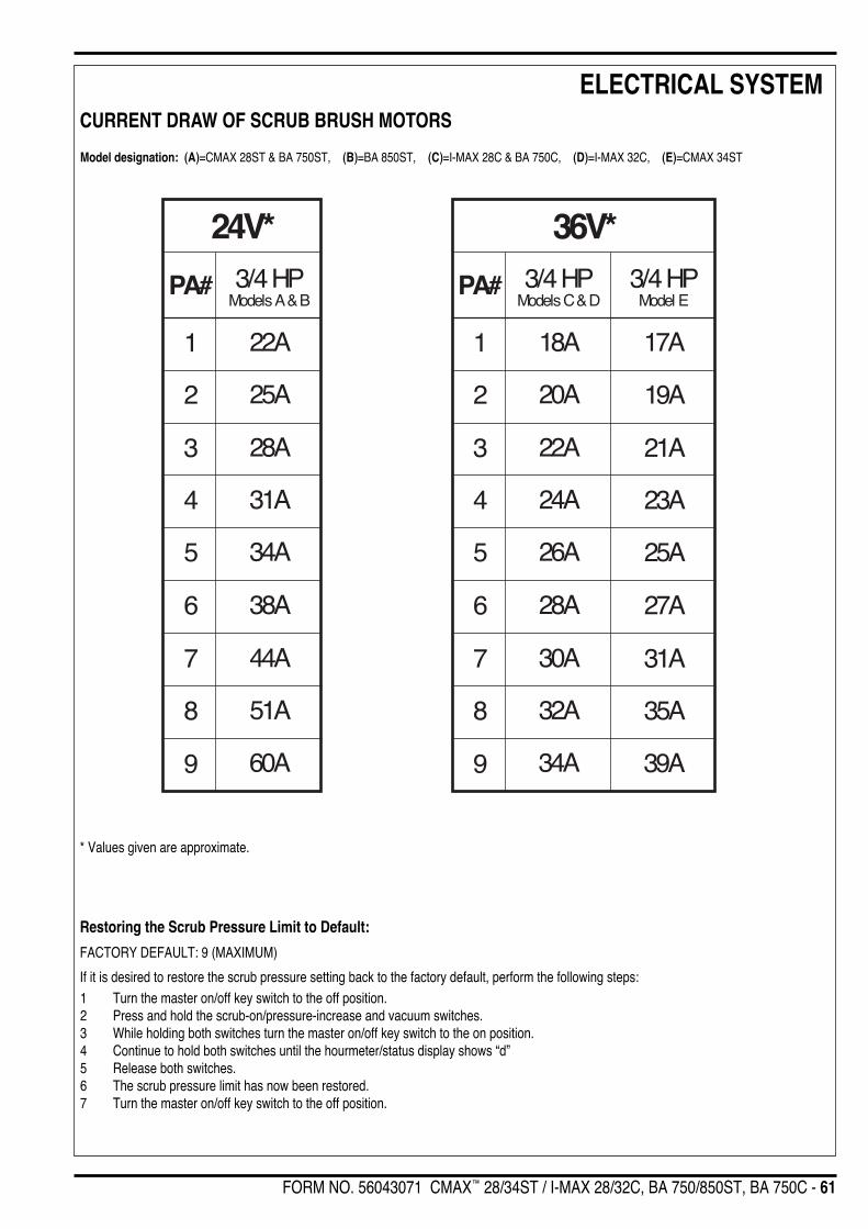
FORM NO. 56043071 CMAX™ 28/34ST / I-MAX 28/32C, BA 750/850ST, BA 750C - 61
ELECTRICAL SYSTEM
24V*
PA# 3/4 HPModels A & B
1
2
3
4
5
6
7
8
9
22A
25A
28A
31A
34A
38A
44A
51A
60A
36V*
PA# 3/4 HPModels C & D
3/4 HPModel E
1
2
3
4
5
6
7
8
9
18A
20A
22A
24A
26A
28A
30A
32A
34A
17A
19A
21A
23A
25A
27A
31A
35A
39A
CURRENT DRAW OF SCRUB BRUSH MOTORS
Model designation: (A)=CMAX 28ST & BA 750ST, (B)=BA 850ST, (C)=I-MAX 28C & BA 750C, (D)=I-MAX 32C, (E)=CMAX 34ST
* Values given are approximate.
Restoring the Scrub Pressure Limit to Default:
FACTORY DEFAULT: 9 (MAXIMUM)
If it is desired to restore the scrub pressure setting back to the factory default, perform the following steps:1 Turn the master on/off key switch to the off position.2 Press and hold the scrub-on/pressure-increase and vacuum switches.3 While holding both switches turn the master on/off key switch to the on position.4 Continue to hold both switches until the hourmeter/status display shows “d”5 Release both switches.6 The scrub pressure limit has now been restored.7 Turn the master on/off key switch to the off position.
62 - FORM NO. 56043071 CMAX™ 28/34ST / I-MAX™ 28/32C, BA 750/850ST, BA 750C
ELECTRICAL SYSTEMSPECIAL PROGRAM OPTIONS (CONTINUED)
Enabling or Disabling the Vacuum Automatic Shutoff Option:
FACTORY DEFAULT: ENABLED
To indicate to the operator that the recovery tank is full, the control system will automatically turn off the vacuum and display “FULL” on thehourmeter/status display if the recovery tank becomes filled. If problems are encountered with the vacuum automatic shutoff feature, such as thevacuum shutting off even if the recovery tank is not full, this feature can be disabled. To enable or disable this feature perform the following steps:1 Turn the master on/off key switch to the off position.2 Press and hold the vacuum switch.3 While holding the vacuum switch turn the master on/off key switch to the on position.4 Continue to hold the vacuum switch until the hourmeter/status display shows “d” (disabled) or “E” (enabled) and the vacuum indicator is
green.5 Release the vacuum switch.6 Pressing and releasing the vacuum switch will now select between “E” (enabled) or “d” (disabled).7 To save the new setting, turn the master on/off key switch to the off position.8 The new setting will be saved and will remain in effect until it is changed again.
Brush Type Selection:
FACTORY DEFAULT: Dependent on machine model
To operate properly and avoid potential damage to the electrical system, the control must be programmed for the type of scrub deck installed onthe machine. There are three possible types. One uses cylindrical brushes and the other two use disc type brushes and pads. This functionconfigures the control unit current settings for each of the scrub deck types. To select the proper type:1 Turn the master on/off key switch to the off position.2 Press and hold the solution switch.3 While holding the solution switch, turn the master on/off key switch to the on position.4 Continue to hold the solution switch until the solution indicator turns green and the hourmeter/status display shows “d”, “C” or “1”.5 Release the solution switch.6 Pressing and releasing the solution switch will now select between the three options. For the cylindrical brush unit select “C”, for the 3/4
HP disc type units (24V & 36V) select “d”. Note: The third displayed selection “1” is not to be used, it is programmed for possible futureengineering use. If “1” is selected electrical overload damage to the brush motors could result (which also would void the warranty).
7 To save the new setting, turn the master on/off key switch to the off position.8 The new setting will be saved and will remain in effect until it is changed again.
CAUTION!Improperly setting this parameter can result in serious damage to the machine. If this is set for 1 HP motors with 3/4 HP motors installedon the machine, the motors may be overloaded which can cause overheating and permanent damage to the motors. It could alsocreate a fire hazard.
Enabling/Disabling the Optional Brush Remove Feature:
FACTORY DEFAULT: DISABLED
With the installation of the optional remove relay kit, disc type machines can be configured for automatic brush removal. The automatic removefunctions are disabled at the factory. If it is desired to enable this feature perform the following steps:1 Turn the master on/off key switch to the off position.2 Press and hold the scrub-off/pressure-decrease and vacuum switches.3 While holding both switches turn the master on/off key switch to the on position.4 Continue to hold both switches until the hourmeter/status display shows “E” or “d” and the vacuum indicator turns red.5 Release both switches.6 Press and release the vacuum switch to select “E” (enabled) or “d” (disabled).7 Turn the master on/off key switch to the off position.
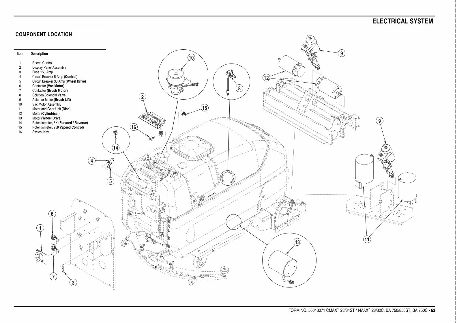
FORM NO. 56043071 CMAX™ 28/34ST / I-MAX™ 28/32C, BA 750/850ST, BA 750C - 63
ELECTRICAL SYSTEM
1113
9
12
9
8
15
10
2
16
14
4
5
6
73
1
Left
sid
e under chassis
COMPONENT LOCATION
Item Description
1 Speed Control2 Display Panel Assembly3 Fuse 150 Amp4 Circuit Breaker 5 Amp (Control)5 Circuit Breaker 30 Amp (Wheel Drive)6 Contactor (Vac Motor)7 Contactor (Brush Motor)8 Solution Solenoid Valve9 Actuator Motor (Brush Lift)10 Vac Motor Assembly11 Motor and Gear Unit (Disc)12 Motor (Cylindrical)13 Motor (Wheel Drive)14 Potentiometer, 5K (Forward / Reverse)15 Potentiometer, 25K (Speed Control)16 Switch, Key
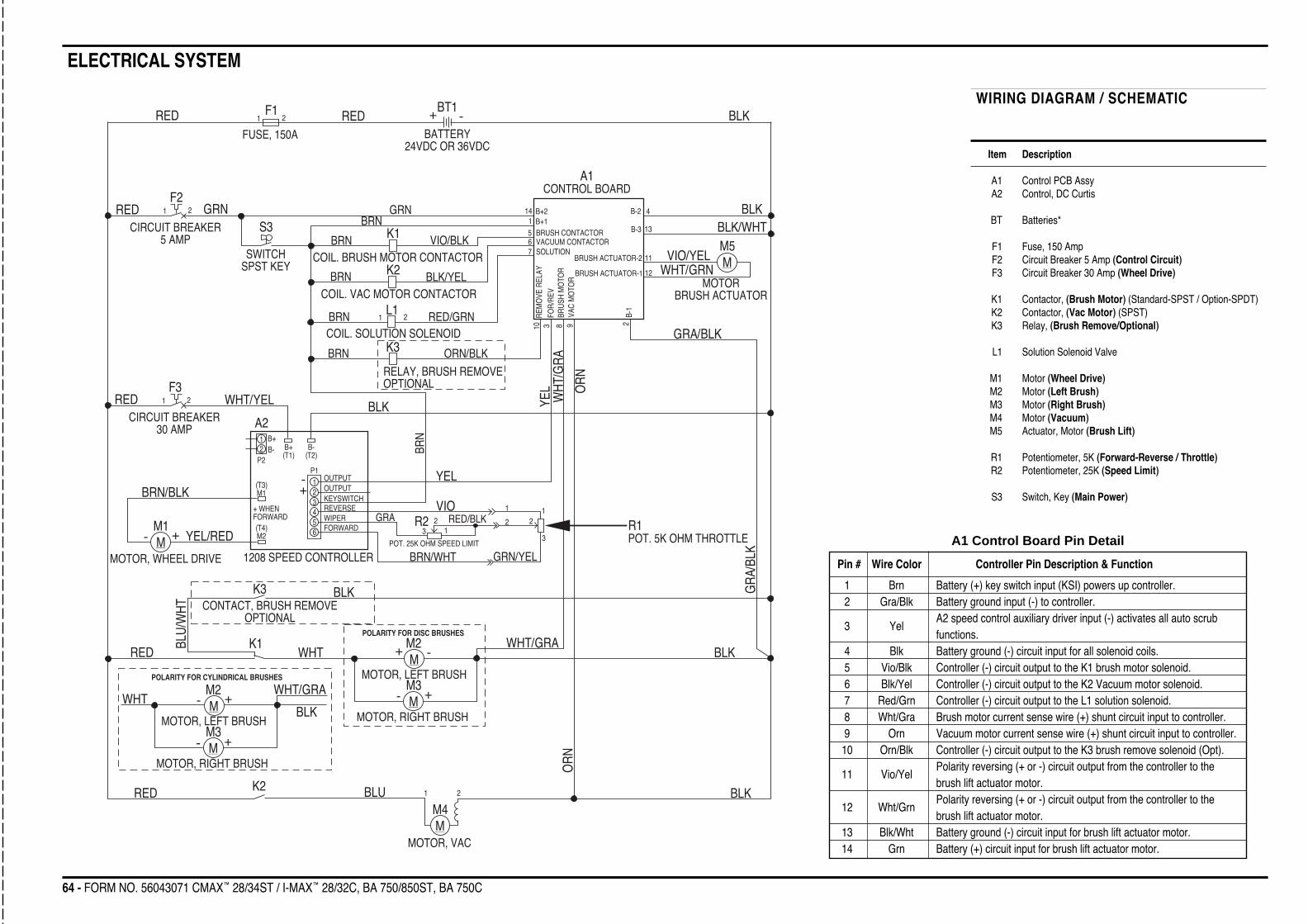
ELECTRICAL SYSTEM
64 - FORM NO. 56043071 CMAX™ 28/34ST / I-MAX™ 28/32C, BA 750/850ST, BA 750C
WIRING DIAGRAM / SCHEMATIC
Item Description
A1 Control PCB AssyA2 Control, DC Curtis
BT Batteries*
F1 Fuse, 150 AmpF2 Circuit Breaker 5 Amp (Control Circuit)F3 Circuit Breaker 30 Amp (Wheel Drive)
K1 Contactor, (Brush Motor) (Standard-SPST / Option-SPDT)K2 Contactor, (Vac Motor) (SPST)K3 Relay, (Brush Remove/Optional)
L1 Solution Solenoid Valve
M1 Motor (Wheel Drive)M2 Motor (Left Brush)M3 Motor (Right Brush)M4 Motor (Vacuum)M5 Actuator, Motor (Brush Lift)
R1 Potentiometer, 5K (Forward-Reverse / Throttle)R2 Potentiometer, 25K (Speed Limit)
S3 Switch, Key (Main Power)
REDFUSE, 150A
F11 2 RED
BT1+ -
BATTERY24VDC OR 36VDC
BLK
BLK
A1CONTROL BOARD
RED GRNF2
1 2
CIRCUIT BREAKER5 AMP
S3
SWITCHSPST KEY
GRN
BLK/WHT4
13
B-2
B-3
M5MVIO/YEL
WHT/GRNMOTOR
BRUSH ACTUATOR
14 B+21 B+1BRN5 BRUSH CONTACTOR
VIO/BLKBRN K1
COIL. BRUSH MOTOR CONTACTOR6 VACUUM CONTACTOR7 SOLUTION
BRN K2 BLK/YELCOIL. VAC MOTOR CONTACTOR
BRN L11 2 RED/GRN
COIL. SOLUTION SOLENOIDK3BRN ORN/BLK
RELAY, BRUSH REMOVEOPTIONAL
11
12
BRUSH ACTUATOR-2
BRUSH ACTUATOR-1
REM
OVE
REL
AYFO
R/R
EVBR
USH
MO
TOR
VAC
MO
TOR
B-1
GRA/BLK
298310
GR
A/BL
K
BLKREDF3
1 2
CIRCUIT BREAKER30 AMP
WHT/YELBR
N
YEL
YEL O
RN
OR
N
BLK
BLK
WH
T/G
RA
WHT/GRA
BLK
M3M
M2M
MOTOR, RIGHT BRUSH
MOTOR, LEFT BRUSH
POLARITY FOR DISC BRUSHES
+ -
+-
1 2
M4M
MOTOR, VAC
BLURED K2
R1POT. 5K OHM THROTTLE
POLARITY FOR CYLINDRICAL BRUSHES
+-
+-
M3M
M2M
MOTOR, RIGHT BRUSH
MOTOR, LEFT BRUSH
WHT/GRA
BLK
WHT
WHT
REDK1
K3
BLU/
WH
T CONTACT, BRUSH REMOVEOPTIONAL
A2
1208 SPEED CONTROLLER
M1M
MOTOR, WHEEL DRIVE
+-
BRN/BLK
YEL/RED
B-(T2)
B+(T1)
B+B-
P2
(T3)M1
(T4)M2
+ WHENFORWARD
P1
12
123456
OUTPUTOUTPUTKEYSWITCHREVERSEWIPERFORWARD
+-
VIO
BRN/WHT GRN/YEL
1
3
2
POT. 25K OHM SPEED LIMIT
1
223 1
RED/BLKGRA R2A1 Control Board Pin Detail
Pin # Wire Color Controller Pin Description & Function
1 Brn Battery (+) key switch input (KSI) powers up controller.2 Gra/Blk Battery ground input (-) to controller.
3 YelA2 speed control auxiliary driver input (-) activates all auto scrubfunctions.
4 Blk Battery ground (-) circuit input for all solenoid coils.5 Vio/Blk Controller (-) circuit output to the K1 brush motor solenoid.6 Blk/Yel Controller (-) circuit output to the K2 Vacuum motor solenoid.7 Red/Grn Controller (-) circuit output to the L1 solution solenoid.8 Wht/Gra Brush motor current sense wire (+) shunt circuit input to controller.9 Orn Vacuum motor current sense wire (+) shunt circuit input to controller.
10 Orn/Blk Controller (-) circuit output to the K3 brush remove solenoid (Opt).
11 Vio/YelPolarity reversing (+ or -) circuit output from the controller to thebrush lift actuator motor.
12 Wht/GrnPolarity reversing (+ or -) circuit output from the controller to thebrush lift actuator motor.
13 Blk/Wht Battery ground (-) circuit input for brush lift actuator motor.14 Grn Battery (+) circuit input for brush lift actuator motor.

FORM NO. 56043071 CMAX™ 28/34ST / I-MAX™ 28/32C, BA 750/850ST, BA 750C - 65
ELECTRICAL SYSTEMA1
CONTROL BOARDGRN 16-2BLK/WHT 18-1WHT/GRN 18-1VIO/YEL 18-1ORN/BLK 18-1ORN 18-1WHT/GRA 18-1
141312111098
7654321
RED/GRN 18-1BLK/YEL 18-1VIO/BLK 18-1BLK 16-2YEL 22-1GRA/BLK 18-1BRN 16-1
X3
GRN 16-2GRN 16-1
S3
SW, SPST KEY
BRN 16-1BRN 16-2
R2POT. 25K OHM SPEED LIMIT
RED/BLK 22-2
RED/BLK 22-1
GRA 22-1
123
BRN/WHT 22-1RED/BLK 22-2VIO 22-1
321
321
GRN/YEL21
X1 X2
1 2
M5MOTOR, BRUSH ACTUATOR
RED
BLKWHT/GRN 18-1VIO/YEL 18-1B B
AA
X12 X11
FOR CYLINDRICAL TYPE BRUSHES
M
GR
N/Y
EL2 1
R1POT. 5K OHM THROTTLE
3 2 1BRN/BLK 10-1YEL/RED 10-1
BRN/WHT 22-1GRA 22-1VIO 22-1BRN 22-1
YEL 22-1
654321
654321
A21208 SPEED CONTROLLER
X19 X18FORWARD
WIPERREVERSE
KEYSWITCH
OUTPUTOUTPUT
K2CONTACTOR, VACUUM MOTOR
K1CONTACTOR, BRUSH MOTOR
(NO CONNECTION)
F1FUSE, 150 A.F2
5 A. CIR. BR.CONTROLS
F330 A. CIR. BR.WHEEL DRIVE
BLK 10-3WHT/YEL 10-1
BLU 10-1
RED 10-2
BRN 16-2BRN 22-1BRN 16-3BLK/YEL 18-1
1 2
34
P1
(T2)B-
(T1)B+ B-
B+
P2
M1(T3)
M2(T4)
+WHENFORWARD
123456
12
WITHOUT BRUSHREMOVE OPTION
WHT/RED 16-1WHT 6-2
BRN 16-3BRN 16-4BRN 16-5
WHT/RED 16-1BLU/WHT 16-1
(NO CONNECTION)
VIO/BLK 18-1
(NO CONNECTION)
1 2
34
BRN
16-
4
BLU
/WH
T 16
-1
BLK
16-1
OR
N/B
LK 1
8-1
WITH BRUSH REMOVE OPTION
WHT/RED 16-1WHT 6-2
BRN 16-3BRN 16-4BRN 16-5
WHT/RED 16-1BLU/WHT 16-1
VIO/BLK 18-1
1 2
34
BRN
16-
4
BLU
/WH
T 16
-1
BLK
16-1
OR
N/B
LK 1
8-15 6
RED 6-1
K1CONTACTOR, BRUSH MOTOR
K3RELAY, BRUSHREMOVE(OPTIONAL)
6 4
B A
RED 6-1
BLK/WHT 18-1BLK 16-1BLK 16-2BLK 10-3BLK 10-2GRA/BLK 18-1BLK 6-1
4
4RED 16-1RED 10-2RED 10-1
56 1
2
3
3
51
2
2 1
BLK 1-2X5TERMINAL BLOCK, (-)
X4TERMINAL BLOCK, (+)
RED 6-1
RED 10-1
RED 16-1
GRN 16-1
WHT/YEL 10-1
RED 1-1 BLK 1-1
BT1BATTERY
24 VDC or 36 VDC
BATTERY DISCONNECT
RED
1-2
X10
X9
(+) (-)
(+) (-)
M4MOTOR, VACUUM
M1MOTOR, WHEEL DRIVE
L1COIL, SOLUTION SOLENOID
RED/GRN 18-1BRN 16-5
YEL/
RED
10-
1
BRN
/BLK
10-
1
BA
A BX8
X17
BLK
WH
T
M
M
AB
AB
12
X15X16
1 2
BLK 10-1BLU 10-1
ORN 18-1BLK 10-2
1 22
SP1
X14X13B BA A
M2
MOTOR,LEFT BRUSH
FOR DISC TYPE BRUSHES
M3
MOTOR,RIGHT BRUSH
NOTE POLARITY OFBRUSH MOTORCONNECTIONS
MOTOR,LEFT BRUSH
MOTOR,RIGHT BRUSHM2 M3
WHT 6-2BLK 6-1
TERMINAL BLOCK (+)X6
TERMINAL BLOCK (-)X7 WHT/GRA 18-1
2
3 1
2
3 1
M M
WHT/GRA 18-1BLK 6-1
TERMINAL BLOCK (-)X7
TERMINAL BLOCK (+)X6
WHT 6-2
2
3 1
2
3 1 BLK
8-1
2
3 1
2
3 1
M M
X23TERMINAL BLOCK (-)
X22TERMINAL BLOCK (+)
WH
T 8-
1
21
21

Austria (Sales Sub)Nilfi sk-Advance GmbH Phone: +43Voralberger Allee 46 1616 58 30 22A-1230 Wien Fax: +43info@nilfi sk-advance.at 1616 58 30 40 www.nilfi sk-advance.atBelgium (Sales Sub)Nilfi sk-Advance NV/SA Phone: +32Doornveld Sphere Business Park (0)2467 60 50 Industrie Asse 3, No. 11 Fax: +32B-1731 Zellik-Asse (0)2463 44 16www.nilfi sk-advance.beCzech Republic (Sales Sub)Nilfi sk-Advance s.r.o. Phone: +420Lysinská 44/1863 2 44 09 09 12143 00 Praha - Modrany +420Czech Republic 2 44 09 09 21 4
Fax: +4202 44 40 23 93
DenmarkNilfi sk-Advance A/S Phone: +45Sognevej 25 43 23 81 00DK-2605 Brøndby Fax: +45mail@nilfi sk-advance.dk 43 43 77 00www.nilfi sk-advance.comDenmark (Prod. Sub)Gerni A/S Phone: +45Myntevej 2 89 12 22 00DK-8900 Randers Fax: +45www.gerni.com 86 43 14 81Denmark (Sales Sub)Nilfi sk-Advance Nordic A/S Phone: +45Sognevej 25A 43 23 40 50 Postbox 344 Fax: +45DK-2605 Brøndby 43 23 40 60 kundeservice@nilfi sk-advance.dkwww.nilfi sk-advance.dkFrance (Sales Sub)Nilfi sk-Advance S.A. Phone: +3327 avenue de la Baltique 1695 98 700Villebon sur Yvette Fax: +33P.B. 246 1695 98 701F-91944 Courtaboeuf Cedexinfo@nilfi sk-advance.frwww.nilfi sk-advance.frGermany (Sales Sub)Nilfi sk-Advance AG Phone: +49Siemensstrasse 25-27 4101 3990Postfach 1361 Fax: +49D-25462 Rellingen 4101 39 91 91info@nilfi sk-advancedewww.nilfi sk-advance.deGreece (Sales Sub)Nilfi sk-Advance A.E. Tel.: +308, Thoukididou Str. 210 963 3443Argioupoli Fax: +30Gr - 164 52 Athens 210 965 0975Greece
Holland (Sales Sub)Nilfi sk-Advance B.V. Phone: +31Camerastraat 9 (2e verdieping) 36 546 07 001322 BB Almere Fax: +31Postbus 60112 36 523 51 481320 AC Almerewww.nilfi sk-advance.nlIreland (Sales Sub)Nilfi sk-Advance Limited Phone: +3528 Sandyford Offi ce Park 3 12 94 38 38Sandyford, Dublin 18 Fax: +35Ireland 3 12 94 38 45Italy (Prod & Sales Sub)CFM SpA Phone: +39Nilfi sk-Advance Div. Guardamiglio 0377 /414021Localita Novella III /45 1124I-26862 Guardamiglio (Mi) Fax: +39
0377 51 443Italy (Prod & Sales Sub)CFM S.p.A. Phone: +39Via Porrettana 1991 059 973 0000I-41059 Zocca (Modena) Fax: [email protected] 059 973 0099Norway (Sales Sub)Nilfi sk-Advance AS Phone: +47Ulvenveien 89C 23 06 75 00N-0581 Oslo Fax: +47
23 06 75 01Poland (Sales Sub)Nilfi sk-Advance Sp.Z.O.O. Phone: +48 05-800 Pruszków 22 738 37 50ul. 3-go MAJA 8 Fax: +48Poland 22 738 37 51Portugal (Sales Sub)Nilfi sk-Advance, Lda. Phone: +35Sintra Business Park 121 911 2670Zona Industrial Da Abrunheira Fax: +35 Edifi cio 1, 1o A 121 911 2679P-2710-089 SintraRussia (Sales Sub)Nilfi sk-Advance LLC Phone: 7Vyatskaya str. 27, bld. 7 095 783 9602127015 Moscow Fax: +7Russia 095 783 9603Spain (Sales Sub)Nilfi sk-Advance S.A. Phone: +34Torre D’Ara 93 741 2400Passeig del Rengle, 5 Pl.10 Fax: +34E-08302 Mataró (Barcelona) 93 757 8020nilfi sk@nilfi sk-advance.esSweden (Sales Sub)Nilfi sk -Advance A/S Phone: +46Sjöbjörnsvägen 5 8555 94400Box 44045 Fax: +46S-100 73 Stockholm 8555 94430info@nilfi sk-advance.sewww.nilfi sk-advance.se

Sweden (Prod.)Nilfi sk-Advance A/S Phone: +46Åmål Branch 5321 7500Strömsbergsgatan Fax: +46Box 127 5321 7595S-662 23 ÅmålSwitzerland (Sales Sub)Nilfi sk-Advance AG Phone: +41Ringsstrasse 19 71 92 38 444Kirchberg/Industrie Stelzl Fax: +41CH-9500 Wil 71 92 35 283www.nilfi sk-advance.chUK (Sales Sub)Nilfi sk-Advance Limited Phone: +44Newmarket Road 1284 763163Bury St. Edmunds Fax: +44UK-Suffolk IP33 3SR 1284 750 562USA (Prod.)Nilfi sk-Advance Inc. Phone: +1 76314600 21.st Avenue North 745 3500Plymouth, MN 55447-3408 Fax: +1 763www.mn.nilfi sk-advance.com 745 3718USA (Sales Sub)Nilfi sk-Advance America Inc. Phone: +1 610300 Technology Drive 647 6420Malvern, PA 19355 Fax: +1 610www.pa.nilfi sk-advance.com 647 6427Canada (Sales Sub)Nilfi sk-Advance Canada Comp. Phone: + 1 905396 Watline Avenue 712 3260Mississauga, Ontario L4Z 1X2 Fax: +1 905
712 3255Australia (Sales Sub)Nilfi sk-Advance Pty. Ltd. Phone: +61(0)248 Egerton Street 9648 2700Silverwater, NSW 2128 Fax: +61(0)2Postal addresse: 9648 2711PO Box 6046Silverwater. NSW 1811info@nilfi sk-advance.com.auwww.nilfi sk-advance.com.auChina (Shenzhen)Nilfi sk-Advance (Shenzhen) Ltd Phone: +86 755Blok 3, Unit 130, 1001 Honghua Road 8359 7937 el.Int. Commercial & Trade Center 8359 7939-42Fuitian Free Trade Zone Fax: +86 755518038 Shenzhen 8359 1063P.R. ChinaChina (Suzhou)Nilfi sk-Advance Professional Phone: +86 512Cleaning Equipment (Suzhou) Co. Ltd. 8918 5656306 Su Hong Zhong Road, Build. 2 Fax: +86 512Suzhou Industrial Park 8918 5666215021 SuzhouP.R. China
Hong Kong (Sales Sub)Nilfi sk-Advance Ltd. Phone: +8522001 HK Worsted Mills Ind’l Bldg., 2427 595131-39 Wo Tong Tsui St. Fax: +852Kwai Chung, Hong Kong 2487 5828Japan (Sales Sub)Nilfi sk-Advance Inc. Phone: +81453-17-40-101 Chigasaki Higashi 942 7741Tsuzuki-ku, Yokohama 224-0033 Fax: +8145 Japan 942 6545Malaysia (Sales Sub)Nilfi sk-Advance Sdn Bhd Phone: +60 3 No. 21, Jalan SS 25/41 7956 8188Mayang Industrial Park Fax: +60 347301 Petaling Jaya 7966 6828Selangor, MalaysiaNew Zealand (Sales Sub)Nilfi sk-Advance Limited Phone: +64(0)9Danish House 525 00926 Rockridge Avenue Fax: +64(0)9Penrose 92-829 525 6440Auckland1135Postal addresse:Private Bag 92 825AucklandNew ZealandSingapore (Sales Sub)Nilfi sk-Advance Pte. Ltd. Phone: + 6522,Woodlands Industrial Park E1 6 7599100Singapore 757740 Fax: +65 sales@nilfi sk-advance.com.sg 7599133Taiwan, ROC (Sales Sub)Nilfi sk-Advance Ltd. Phone: +886 Taiwan Branch (H.K.) 2 2239 88121F, No. 193, Sec.2 Fax: +886 Xing Long Rd., Taipei 2 2239 8832Taiwan, R.O.C. Thailand (Sales Sub)Nilfi sk-Advance Co. Ltd. Phone: +66 289 Soi Chokechai-Ruammitr 275-5630Viphavadee-Rangsit Road Fax: +66 2Ladyao, Jatuchak, Bangkok 10900 691-4079Thailand

www.nilfisk-advance.com © 2004 Printed in USA