cma90 90lpm advanced independent-metering …pub/@eaton/@hyd/...2 eaton cma90 technical document...
TRANSCRIPT

CMA90Advanced Independent-Metering Mobile Valve
90LPM 440 bar CAN Bus Technical Document

EATON CMA90 Technical Document E-VLMB-BB003-E1 September 2016 2
Contents
Introduction 3
CMA90 Specifications and Performance 4
CMA Cross Sections 5–6
CMA90 Installation Views (5 section Standard EH Valve) 7–8
CMA90 Installation Views (5 Section with manual override) 9–10
CMA Machine Integration Process 11
Specifying a CMA System 12
Model Code For Inlet Section 13
Model Code – Work Section 14
CMA Software Options 15
CMA Wiring Harness Details 16–18
Pro-FX® Configure 19

EATON CMA90 Technical Document E-VLMB-BB003-E1 September 2016 3
The CMA90 is an advanced CAN-Enabled electro-hydraulic sectional mobile valve with independent metering that utilizes pressure and position sensors, on board electronics, and advanced software control algorithms. Where conventional mobile valves often compromise on precision or response, the CMA delivers both. The CMA offers high performance with sub micron hysteresis, closed loop control over the spool position, and repeatable performance.
CMA offers customers the next generation in advanced mobile valves with unlimited possibilities to differentiate your machine capabilities.
Key Benefits of this advanced mobile valve include:
• Precise control maintained for all load conditions
• Reduction in metering losses / energy management
• High valve responsiveness
• Flow Sharing – Pre and Post Comp Capabilities
• Flexibility in configuration / easily change parameters
• Command factory-calibrated flow or pressure from either work port
• Easier communication with the valve
• Reduced load on the Vehicle CAN bus
• Advanced Diagnostics for improved reliability and productivity• Hose Burst Detection• Limp mode• Diagnostics on the inlet, tank, load sense, work port pressures,
spool position, consumed flow, and oil temperature.
• Platform can support future software development for future product development.
• Reliable performance across a broad temperature range
Introduction

EATON CMA90 Technical Document E-VLMB-BB003-E1 September 2016 4
CMA90 Specifications and Performance
Inlet Rated 380 bar (5511 psi)Inlet Max 440 bar (6382 psi)Work Port Rated 380 bar (5511 psi)Work Port Max 440 bar (6382 psi)Tank* Max 30 bar (435 psi)
Flow
Work Port (max, measured with internal pressure sensors) 90 lpm (24 gpm) @ 7.5 bar Δ PMax inlet flow when two sections are fully open. 200 lpm (53 gpm) @ 25 bar P-T
Leakage**
Max Leakage without Work Port Valves 30 cc @100 bar @ 21 cstMax Leakage with Work Port Valves 40 cc @100 bar @ 21 cst
Construction
Sectional Up to 8 sections per block Up to 15 sections per VSM
Port Types
SAE P1 = 7/8”-14 UNF (SAE-10), P2 = 1 1/16”-12 UN (SAE-12), T = 1 1/16”- 12 UN (SAE-12), LS = 7/16”-20 UNF (SAE-04), A&B = 3/4”-16 UNF (SAE- 08) OR 7/8”-14 UNF (SAE-10)BSP P1=G 1/2, P2=G 3/4, T=G 3/4, LS=G 1/4, A&B = G 1/2
Inlet section options
Variable Displacement (Load Sensing)
Work section options
Standard Spools 90 lpm (24 gpm)Work Port Valves Anti-Cavitation Port Relief & Anti-Caviation Port Relief
Compensation type
Digital On meter-in and meter-out
Actuation
Primary CANEmergency Mechanical Override
Control modes
Flow Pressure Spool Position Float
Ambient (operating) -40°C to 105°CStandard Oil (operating)***** -40°C to 85°CExtended Oil (operating) -20°C to 105°CStorage -40°C to 105°C
Filtration
ISO 4406 18/16/13Pressure Reducing Valve 75 micronPilot Valve 100 micron
Electromagnetic protection
EMC Directive 2014/30/EC *** Earth Moving ISO 13766: 2006Construction EN 13309: 2010Agriculture ISO 14982:2009
Electrical environmental****
Ingress Protection IP67Thermal Cycling -40C to 105C for 1000 cyclesMechanical Shock 50G ½ sine wave, 11ms pulseRandom VibrationMethod MIL STD 202G, Method 214-1Limits Test Condition A Duration 8 hrs/axis # Of Axis 3 separatelyProfile Reference Appendix
Oil Temperature viscosity
Recommended Viscosity 85 to 10 cStAbsolute Maximum Viscosity 2250 cStAbsolute Minimum Viscosity 7 cSt
Electrical
Input Voltage 9 - 32 VDCPower Consumption Range Reference AppendixCAN Interface J1939 2.0B, CAN Open
Electrical interface connectors
Deutsch (VSM) DT06-12SB-P012 Deutsch (VSE) DT06-12SA-P012
Dynamic performance
Loop Time for Internal CAN 3ms Typical Step Response 24 ms @ 15 cStTypical Frequency Response 17.5 Hz @ 15 cSt
Pressures Temperatures
* With manual override, tank limited to 10 bar (145 psi) maximum. Max 30 bar is at constant rate.
**Data taken from work port to tank and supply
***Electronics are designed to power down and recover automatically under various power conditions (ie.. Load Dump, Ignition Cranking, Disconnection of Inductive Loads). CE testing with J1939 at 250 kb/s
****Additional Electrical Environmental tests were performed. Contact Eaton for additional details, if desired.
*****It is recommended that the CMA valves not be subjected to a thermal difference of greater than 50°F (28°C).

EATON CMA90 Technical Document E-VLMB-BB003-E1 September 2016 5
CMA Cross Sections
Valve cross section:
1. Pilot Valve
2. Main Stage
3. Linear Position Sensor
4. Port Reliefs / Anti-Cavs
5. Main Metering Spools
6. Work Port A
7. Work Port B
1
2
3
4
7
5
6

EATON CMA90 Technical Document E-VLMB-BB003-E1 September 2016 6
Principles of Operation
The work section is comprised of two independent spools that act as a pair working to control double acting services, or alternatively as single spools controlling a single acting service (2 single axis services can be controlled from any work section).
Demands to each work section are transmitted over a CAN Bus
and power is provided to each work section via a single daisy chain cable arrangement. Each work section has a single pilot valve comprised of on-board electronics, embedded sensors, and two independent 3 position 4 way pilot spools driven by a low power embedded micro controller.
The independent pilot spools control the mainstage spools. Closed loop control of each work section is done locally by leveraging the on-board electronics and sensors.
Each mainstage spool has its own position sensor enabling closed loop position control of the mainstage spool.
Further, a pressure sensor is located in each work port, pressure line and tank line.
With the up and downstream pressure information known at any time, flow delivered to the service can be controlled by moving the spools to create the appropriate orifice area for the desired flow rate.
CMA Cross Sections
Figure 1: CMA system with Load-Sensing Inlet & a single work-section
Figure 2: Extension Inlet

CMA90 Installation Views (5 section Standard EH Valve)
Maximum OverallEnvelop
Right
Top
Left
EATON CMA90 Technical Document E-VLMB-BB003-E1 September 2016 7

EATON CMA90 Technical Document E-VLMB-BB003-E1 September 2016 8
CMA90 Installation Views (5 section Standard EH Valve)
Maximum OverallEnvelop
213.2
181.8
Back
Front

CMA90 Installation Views (5 Section with manual override)
Right
Top
Left
EATON CMA90 Technical Document E-VLMB-BB003-E1 September 2016 9

EATON CMA90 Technical Document E-VLMB-BB003-E1 September 2016 10
CMA90 Installation Views (5 Section with manual override)
Maximum Overall Envelopfor valve with manual override
232.3
268.2
14º
14º
Back
Front

CMA Machine Integration Process
Because of CMA’s CAN communication and advanced software features, there are a couple of other additional steps to integrating a CMA valve into your machine. The following steps outline a typical integration process.
1. Specify Inlet and Sections and Purchase Valve Block assemblies, Please reference page 15 "Specifying a CMA system" for more information.
2. Develop software for CAN communication to CMA as well as the machine’s application software
a. Communication libraries in CoDeSys 3.5.5 are available for use on Eaton’s HFX Controller or other CoDeSys programmed ECUs
b. If programming in another language, reference CMA’s Application Developer’s Guide for J1939 or CANOpen for definition of the necessary communication message structure.
3. Design and build wiring harnesses to connect from the machine to each CMA system as well as harnesses to connect between CMA valve blocks.
a. Cables connecting valves within a blocks will be provided by Eaton
b. See wiring schematic and suggested components Please reference page 27 “CMA Wiring Harness Details” for more information.
4. Procure CAN card Please reference page 34 “Pro-FX® Configure” for more information.
5. Once the CMA valve is received and installed on the machine, setup and tune CMA’s software features using Pro-FX® Configure.
EATON CMA90 Technical Document E-VLMB-BB003-E1 September 2016 11

• One and only one VSM and Inlet Pressure Controller are required per system
• Maximum of 8 work sections per block
• Maximum of 15 work sections per system
• If more than 15 work sections are required, this can be accomplished by using additional CMA systems. Each additional system will appear as another node on the User CAN network
Specifying a CMA System
For each CMA valve block desired, develop 1 inlet section model code and a work section model code for each work section on the block. When dividing work sections across multiple valve blocks, the following rules must be followed. Note, a system here refers to all of the valve blocks wired electrically together to a single VSM.
Valve block order example
1. Inlet CMA090 J M S V 3 0 000 K 1 00 XXA 10
2. Section 1 CMZ090 B MC B 379 MC B 379 0 K 1 00 XXA 10
3. Section 2 CMZ090 B MC B 379 MC B 379 0 K 1 00 XXA 10
4. Section 3 CMZ090 B MC B 379 MC B 379 0 K 1 00 XXA 10
Note: Repeat section model code for additional sections.
Note: End cover, tie rods, and cables to connect between the valves on the block are provided by default.
EATON CMA90 Technical Document E-VLMB-BB003-E1 September 2016 12

Model Code For Inlet Section
1 CMA090 Series
2 Communication Protocol J J1939 C CAN OPEN 0 None
3 Interface Module M VSM E VSE 0 None
4 Port Types S SAE P1 = 7/8”-14 UNF (SAE-10) P2 = 1 1/16”-12 UN (SAE-12) T = 1 1/16”- 12 UN (SAE-12) LS = 7/16”- 20 UNF (SAE-04) B BSP P1= G 1/2 P2= G 3/4 T = G 3/4 LS= G 1/4
5 Inlet Pressure Controller V Variable Displacement 0 none, Used on VSE or extension block
6 Active Pressure Port 1 P1 2 P2 3 P1 & P2
7 Manual Override 0 None M Manual Override on CV
8 Main Relief Setting (In bar) 000 = None 155 293 172 310 190 328 207 345 224 362 241 379 259 397 276 414
9 Paint Type K Std. Flat Black
10 Seals 1 Default
11 Special Features 00 None
12 Software Version XXA Standard Software
13 Design Code 10 Design Code
21 4
CMA090 * * * * * * *** * * ** *** **
5 98 11 13123 6 7 10
Note: A pressure limit can be set on the valve in software to any value in increments of 0.01 bar using available configuration software suite. This applies to both inlet and work port settings.
EATON CMA90 Technical Document E-VLMB-BB003-E1 September 2016 13

EATON CMA90 Technical Document E-VLMB-BB003-E1 September 2016 14
21 4
CMZ090 * ** * *** ** * *** * * ** *** ** **
5 98 11 13 14123 6 7 10
Model Code – Work Section
1 CMZ090 Series
2 Body Port Thread Sizes A 3/4” 16 UNF (SAE-8)
B 7/8” 14 UNF (SAE-10) D G 1/2”
3 Spool Type at Position A MC 90 lpm, biased to center MT 90 lpm, biased to tank MP 90 lpm, biased to pressure
4 Valve Option at A 0 None B Anti-cavitation valve with relief valve C Anti-cavitation valve S Relief valve
5 Relief Setting at Position A RV Setting in Bar 000 = None 155 293 172 310 190 328 207 345 224 362 241 379 259 397 276 414
6 Spool Type at Position B MC 90 lpm, biased to center MT 90 lpm, biased to tank MP 90 lpm, biased to pressure
7 Valve Option at B 0 None B Anti-cavitation valve with relief valve C Anti-cavitation valve S Relief valve
8 Relief Setting at Position B RV Setting in Bar 000 = None 155 293 172 310 190 328 207 345 224 362 241 379 259 397 276 414
9 Manual Override Type 0 None A Lever-handle toward port A B Lever-handle toward port B
10 Paint Type K Std. Flat Black
11 Seal 1 Default (NBR)
12 Special Features 00 None
13 Software Version XXA Standard Software XXU Advanced Control Package XXV Advanced Service Package XXT All Packages (Standard plus all Advanced Packages)
14 Design Code 10 Design Code
Note: A pressure limit can be set on the valve in software to any value in increments of 0.01 bar using available configuration software suite. This applies to both inlet and work port settings.
Note: If an option without a relief is selected for port A or B, no relief valve setting should be selected in corresponding Relief Setting position (i.e., select 000). Likewise, when selecting a valve option with a relief, make sure to select a corresponding relief setting.

EATON CMA90 Technical Document E-VLMB-BB003-E1 September 2016 15
CMA Software Options
Software Description
Pressure compensated flow control Load-independent flow control Flow compensated pressure control Single service pressure control while either sinking or sourcing flow.Intelli float Lowers the load at a configurable rate and then enters full float modeStandard ratio flow share Pre or post comp capabilities in one valve block. All service flow demands are reduced by the (with priority capability) same ratio. Can also exempt services from flow-sharing to maintain priority. This feature prevents the pump from saturating when flow demands to the valve sum to be larger than the pump can provide.Intelligent twin spool flow control (IFC) Versatile flow controller which maintains the desired flow independent of transitions
between passive and overrunning loadsLoad damping A feature of IFC and UFC which reduces service oscillation induced by moving large structures, such as a boom.Electronic load sense enabled Enables operation with a compatible pump or when multiple CMA systems are present
on the same CAN networkElectronic work port relief valve Configurable electronically controlled relief valve against externally applied loadsElectronic work port pressure limit (feed reducer) Configurable electronically controlled pressure limit applied to user flow demands
without consuming additional pump flowSingle spool flow control Sink or source flow on individual service portsSingle spool position control Direct spool position control on each spoolSmart Data Diagnostics on all on-board sensors. Inlet, Tank, LS, Work Port pressures, Spool Positions, oil
temperature sensor data availability.
A - Standard software control features
Software Description
Torque Control Advanced force or torque control for double-acting cylinders or motorsData control package Broadcast of each spool’s flow consumptionCascade and Uniform Flow Share Cascade: maintains demanded flow to selected high priority services by reducing flow to lowest priority services Uniform: All flow demands are reduced by the same absolute amount
(i.e. all reduced by 1 lpm)
Software Description
Hose burst detection Prevents major oil spill events by monitoring flow consumption on each service and closing the spools for that circuit if a major leak is detected
Limp mode If a sensor fails, the valve will continue to work with reduced performance until the machine can be serviced
U – Advanced control package
V – Advanced service package
T – All Packages
Includes Standard, Advanced Control, and Advanced Service packages

EATON CMA200 Technical Document E-VLMB-BB002-E July 2015 7
User CAN Diagram
8 ICAN HIGH A
8 ICAN HIGH A
4 UCAN LOW B
12 BATTERY -7 ICAN TERMINATE
4 UCAN LOW B
12 BATTERY -7 ICAN TERMINATE
Valve Block 1
Eato
n Va
lve
Syst
em
Mod
ule
(VSM
)
Mid
dle
of U
ser C
AN
Net
wor
k
Valve Block 1
User CAN Connection
5 UCAN HIGH A
3 UCAN LOW A
2 SHIELD
6 UCAN TERMINATE
10 ICAN HIGH B11 ICAN LOW B
1 BATTERY + 9-32 VDC
9 ICAN LOW A
5 UCAN HIGH A
3 UCAN LOW A
2 SHIELD
6 UCAN TERMINATE
10 ICAN HIGH B11 ICAN LOW B
1 BATTERY + 9-32 VDC
9 ICAN LOW A
Eato
n Va
lve
Syst
em
Mod
ule
(VSM
)
End
of U
ser C
AN
Net
wor
k
User CAN Device 2
User CAN Device 1
User
CAN
Net
wor
k
User
CAN
Net
wor
k
CAN
H
CAN
L
CAN
H
CAN
L
User CAN Device 1
User CAN Device 2
User CAN Connection
User CAN, or UCAN, is the machine’s CAN network that communicates with the VSM.If the VSM is at the end of the UCAN network, a 120 ohm termination resistor built into the VSM can be used to terminate the UCAN with the installation of a wire jumper, as shown in the left figure below. If the VSM is in the middle of the bus, no UCAN termination is necessary. The UCAN lines to the VSM must be a stub off of the main CAN harness, as shown in the right figure below.
User Cables Termination
CMA Wiring Harness Details
Note: Symbol is used to represent twisted pair wires. Shielding is option and was not used to a CE EMC limits..
EATON CMA90 Technical Document E-VLMB-BB003-E1 September 2016 16

Single block system
EATON CMA200 Technical Document E-VLMB-BB002-E July 2015 8
5 UCAN HIGH A
2 SHIELD
4 UCAN LOW B
10 ICAN HIGH B
12 BATTERY -1 BATTERY + 9-32 VDC
7 ICAN TERMINATE
9 ICAN LOW A8 ICAN HIGH A
11 ICAN LOW B
6 UCAN TERMINATE
3 UCAN LOW A120
OHM
VSM
User CAN Connection
1 BATTERY + 9-32 VDC
7 ICAN TERMINATE
9 ICAN LOW A8 ICAN HIGH A
11 ICAN LOW B
6 SECOND VSE ID
2 SECOND VSE ID RETURN
NC
NC
NC
10 ICAN HIGH B
12 BATTERY -
User CAN Connection
5 UCAN HIGH A
3 UCAN LOW A
2 SHIELD
4 UCAN LOW B
10 ICAN HIGH B
12 BATTERY -1 BATTERY + 9-32 VDC
7 ICAN TERMINATE
9 ICAN LOW A8 ICAN HIGH A
11 ICAN LOW B
6 UCAN TERMINATEValve Block 1
Valve Block 2
120OHM
VSE
VSM
120OHM
User CAN Connection
CASE SCREW
Double block system with valve system extender (VSE)
EATON CMA200 Technical Document E-VLMB-BB002-E July 2015 8
5 UCAN HIGH A
2 SHIELD
4 UCAN LOW B
10 ICAN HIGH B
12 BATTERY -1 BATTERY + 9-32 VDC
7 ICAN TERMINATE
9 ICAN LOW A8 ICAN HIGH A
11 ICAN LOW B
6 UCAN TERMINATE
3 UCAN LOW A120
OHM
VSM
User CAN Connection
1 BATTERY + 9-32 VDC
7 ICAN TERMINATE
9 ICAN LOW A8 ICAN HIGH A
11 ICAN LOW B
6 SECOND VSE ID
2 SECOND VSE ID RETURN
NC
NC
NC
10 ICAN HIGH B
12 BATTERY -
User CAN Connection
5 UCAN HIGH A
3 UCAN LOW A
2 SHIELD
4 UCAN LOW B
10 ICAN HIGH B
12 BATTERY -1 BATTERY + 9-32 VDC
7 ICAN TERMINATE
9 ICAN LOW A8 ICAN HIGH A
11 ICAN LOW B
6 UCAN TERMINATEValve Block 1
Valve Block 2
120OHM
VSE
VSM
120OHM
User CAN Connection
CASE SCREW
Interconnect CAN, or ICAN, is the CAN network between the VSM and VSE’s.120 ohm termination resistors in the VSM and VSE’s circuits can be connected with the installation of wire jumpers each device. Two sets of ICAN pins are available in a VSM or VSE to allow daisy chaining ICAN if a VSM/VSE is in the middle of the CMA system. If no VSE’s exist in a system, it is still necessary to install a jumper to activate one 120 ohm termination resistor on the ICAN bus.
Interconnect CAN Termination
CMA Wiring Harness Details
EATON CMA90 Technical Document E-VLMB-BB003-E1 September 2016 17

Example bench testing harness
Eato
n Va
lve
Syst
emM
odul
e (V
SM)
Banana plug (Red)
DSUB connector(9 PIN female)
Battery + 9-32 VDC Battery + 9-32 VDCBattery -I CAN terminateI CAN high B
I CAN high A
I CAN low B
I CAN low A
UCAN low BUCAN low AUCAN high AShield
UCAN terminate
User CAN low 2User CAN high 7CAN shield 3
Battery -Banana plug (Black)
CMA Wiring Harness Details
When connecting to a CMA valve not installed on a machine, for example on a test bench, wiring is necessary to provide electrical power and CAN communication to a CAN card. The schematic below could be used to connect to a 1 block CMA system. The schematic would need to be modified per the previous wiring harness pages if there were additional blocks within the system that had VSE’s.
EATON CMA90 Technical Document E-VLMB-BB003-E1 September 2016 18
EATON CMA90 Technical Document E-VLMB-BB003-E1 September 2016 19
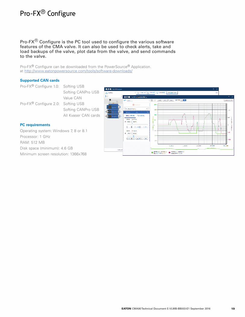
Pro-FX® Configure
Pro-FX® Configure can be downloaded from the PowerSource® Application. at http://www.eatonpowersource.com/tools/software-downloads/
Supported CAN cards
Pro-FX® Configure 1.0: Softing USB
Softing CANPro USB
Value CAN
Pro-FX® Configure 2.0: Softing USB
Softing CANPro USB
All Kvaser CAN cards
PC requirements
Operating system: Windows 7, 8 or 8.1
Processor: 1 GHz
RAM: 512 MB
Disk space (minimum): 4.6 GB
Minimum screen resolution: 1366x768
Pro-FX® Configure is the PC tool used to configure the various software features of the CMA valve. It can also be used to check alerts, take and load backups of the valve, plot data from the valve, and send commands to the valve.
© 2016 EatonAll Rights ReservedPrinted in USA Document No. E-VLMB-BB003-E1 September 2016
Eaton Hydraulics Group USA14615 Lone Oak RoadEden Prairie, MN 55344USATel: 952-937-9800Fax: 952-294-7722www.eaton.com/hydraulics
Eaton Hydraulics Group EuropeRoute de la Longeraie 71110 MorgesSwitzerlandTel: +41 (0) 21 811 4600Fax: +41 (0) 21 811 4601
EatonHydraulics Group Asia PacificEaton BuildingNo.7 Lane 280 Linhong RoadChangning District,Shanghai 200335ChinaTel: (+86 21) 5200 0099Fax: (+86 21) 2230 7240