cm317d stop - objects.eanixter.com
TRANSCRIPT

STOP
READ ALL OF THE FOLLOWING INSTRUCTIONS BEFORE REMOVING CABINET FROM SKID
CM317D

INSTRUCTIONS CM317D© Panduit Corp. 2010,2011
FOR TECHNICAL SUPPORT www.panduit.com/resources/install_maintain.asp
NET-ACCESS Cable Management Cabinets
CN1/CN1CN CN2/CN2CN(1) Base Cabinet(2) Solid Side Panels(1) Dual Hinge Door(1) Split Door Set(2) Cable Management Finger Kits(1) Bezel and Removable Cover Kit(1) Hardware KitCN1:(2) #12-24 Threaded Equipment Rail SetsCN1CN: (2) Cage Nut Equipment Rail Sets
(1) Base Cabinet(1) Dual Hinge Door(1) Split Door Set(2) Cable Management Finger Kits(1) Bezel and Removable Cover Kit(1) Hardware KitCN2: (2) #12-24 Threaded Equipment Rail SetsCN2CN: (2) Cage Nut Equipment Rail Sets
(1) Base Cabinet(2) Solid Side Panels (2) Split Door Sets(2) Cable Management Finger Kits(1) Bezel and Removable Cover Kit(1) Hardware Kit(2) #12-24 Threaded Equipment Rail Sets
CN4
Page 2 of 20
Other cabinet configurations covered by this instruction sheet: CN1CNNU, CN1CNU, CN1NU, CN2C, CN2CNNU, CN2CNU, CN2NU, CN3C, CN3CNNU, CN3CNU, CN3CFR, CN4C, CN5C, CN5NU
(1) Base Cabinet(2) Split Door Sets(2) Cable Management Finger Kits(1) Bezel and Removable Cover Kit(1) Hardware Kit(2) #12-24 Threaded Equipment Rail Sets
CN5
CN3/CN3CN(1) Base Cabinet(2) Cable Management Finger Kits(1) Bezel and Removable Cover Kit(1) Hardware KitCN3: (2) #12-24 Threaded Equipment Rail SetsCN3CN: (2) Cage Nut Equipment Rail Sets
NOTE-Some views in this documentmay vary slightly from your actualcabinet configuration.

INSTRUCTIONS CM317D
For Technical Support: www.panduit.com/resources/install_maintain.asp
Thermal Ducting for Cisco 6509/6509E Series(CNAE1)
Accessory Guide
Caster Kit(CNCSTR)
Dual Hinging Door(CNDDE)
Solid Side Panel(CNPS)
Split Doors(CNDS)
Finger Kit(CNBRFK)
End Spool Kit(CNSPE)
Center Spool Kit(CNSPC)
Thermal Ducting for Cisco 9513 Series(CNAE2)
Page 3 of 20
Cabinet Rails Tapped Holes(CNRT)
Cabinet Rails Cage Nuts(CNRC)
Thermal Ducting for Cisco 6513 Series(CNAE3)

INSTRUCTIONS CM317D
For Technical Support: www.panduit.com/resources/install_maintain.asp
Packing Material RemovalAfter removing stretch wrap and outer cardboard shell, remove the four (4) lag bolts that hold the cabinet to the pallet using a 7/16”(11mm) socket. (As Shown)
Page 4 of 20
Before removal of packaging material:Check tip indictor on the outside of cabinet to ensure cabinet was shipped in the upright position.
Note: Doors and Side panels are removed for clarity.See pages 13 thru 17 for door removal and pages 18 and 19 for side panel removal.
Bolt Locations
Base Cabinet
Using two people, lift the cabinet off of the skid. Use the J-Hooks as handles.
If cabinet has side panels, remove side panels for easier removal of the cabinet from skid
J-Hooks

INSTRUCTIONS CM317D
For Technical Support: www.panduit.com/resources/install_maintain.asp
Page 5 of 20
Shipping Bracket RemovalThere are two (2) bracket used for shipment of the Front door and four(4) brackets for shipment of side panels. Remove brackets prior to use of the cabinet see below.
Side Panel Brackets
Door Brackets
INSTRUCTIONS CM317D
For Technical Support: www.panduit.com/resources/install_maintain.asp
Page 6 of 20
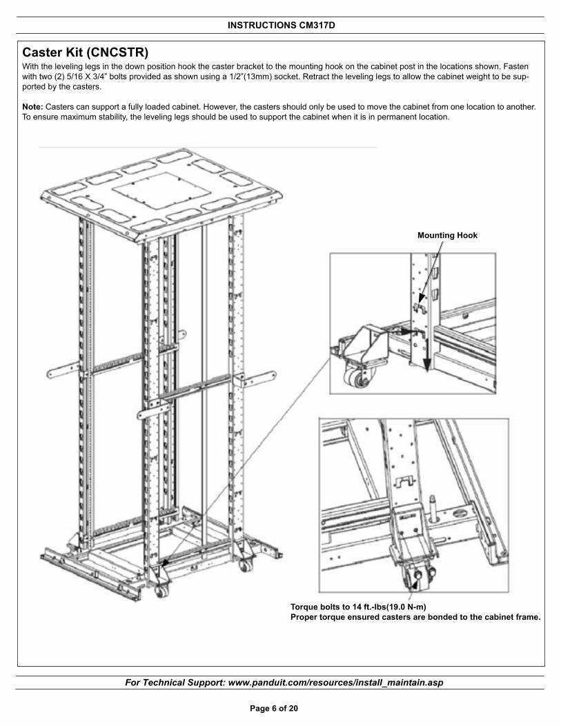
Caster Kit (CNCSTR)With the leveling legs in the down position hook the caster bracket to the mounting hook on the cabinet post in the locations shown. Fasten with two (2) 5/16 X 3/4” bolts provided as shown using a 1/2”(13mm) socket. Retract the leveling legs to allow the cabinet weight to be sup-ported by the casters.
Note: Casters can support a fully loaded cabinet. However, the casters should only be used to move the cabinet from one location to another. To ensure maximum stability, the leveling legs should be used to support the cabinet when it is in permanent location.
Mounting Hook
Torque bolts to 14 ft.-lbs(19.0 N-m)Proper torque ensured casters are bonded to the cabinet frame.

INSTRUCTIONS CM317D
For Technical Support: www.panduit.com/resources/install_maintain.asp
Page 7 of 20
LevelingOnce the leveling legs are fully retracted use two people to slide the cabinet into the desired location. Lower the leveling legs using a 3/8” (10mm) deep well socket, until the cabinet weight is fully supported. Use a bubble level placed on the base rails in the locations shown to adjust legs until the cabinet is level. For ganged cabinet applications, ensure that adjacent cabinets are adjusted to the same height, parallel with each other, and no gaps at the top or bottom between cabinets.
Note: The maximum weight load of the cabinet is 2500 pounds (1134 kg). The weight load should be evenly distributed across the height of the cabinet, with the heaviest components mounted at the bottom of the cabinet.
Front-to-Back Cabinet Leveling
Side-to-Side Cabinet Leveling
3/8” socket
3/8” socket

INSTRUCTIONS CM317D
For Technical Support: www.panduit.com/resources/install_maintain.asp
J-Hook Removal (Optional)J-hooks provide support the side panel and can be used for moving the cabinet. For ganged cabinet applications, the J-Hooks can be removed to provide greater access between cabinets. The J-Hooks can be removed by removing the two screws mounted to the cabinet rail.
Page 8 of 20
Screws
Vertical Post
INSTRUCTIONS CM317D
For Technical Support: www.panduit.com/resources/install_maintain.asp
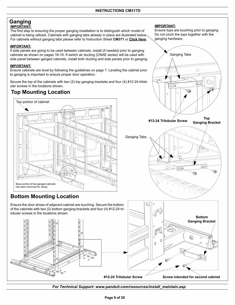
Ganging
Page 9 of 20
IMPORTANT:If side panels are going to be used between cabinets, install (if needed) prior to ganging cabinets as shown on pages 18-19. If switch air ducting (CNAE series) will be used with side panel between ganged cabinets, install both ducting and side panels prior to ganging.
IMPORTANT:Ensure tops are touching prior to ganging. Do not cinch the tops together with the ganging hardware.
Top Mounting Location
IMPORTANT:Ensure cabinets are level by following the guidelines on page 7. Leveling the cabinet prior to ganging is important to ensure proper door operation.
#12-24 Trilobular Screw
BottomGanging Bracket
Bottom Mounting Location
Screw intended for second cabinet
Base portion of two ganged cabinets has been removed for clarity.
Ensure the door shoes of adjacent cabinet are touching. Secure the bottom of the cabinets with two (2) bottom ganging brackets and four (4) #12-24 tri-lobular screws in the locations shown.
Secure the top of the cabinets with two (2) top ganging brackets and four (4) #12-24 trilob-ular screws in the locations shown.
#12-24 Trilobular ScrewTop
Ganging Bracket
Top portion of cabinet
IMPORTANT:The first step to ensuring the proper ganging installation is to distinguish which model of cabinet is being utilized. Cabinets with ganging tabs already in place are illustrated below. For cabinets without ganging tabs please refer to Instruction Sheet CM371 or Click Here.
Ganging Tabs
Ganging Tabs
INSTRUCTIONS CM317D
For Technical Support: www.panduit.com/resources/install_maintain.asp
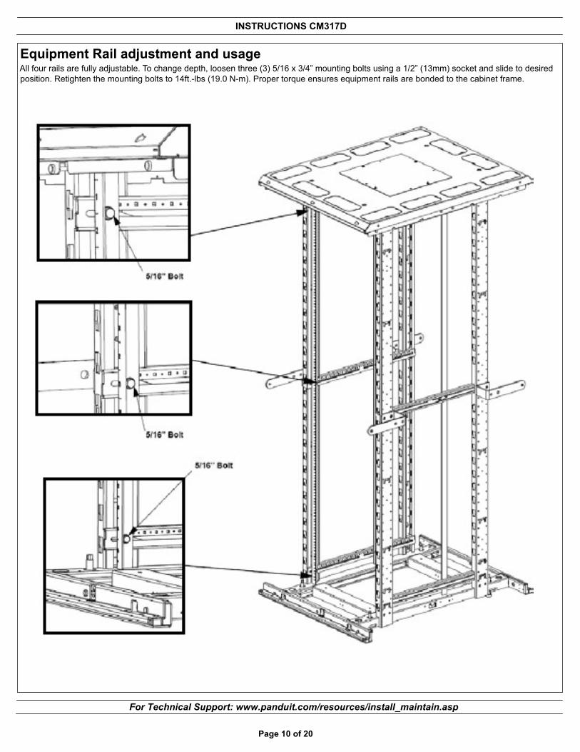
Equipment Rail adjustment and usageAll four rails are fully adjustable. To change depth, loosen three (3) 5/16 x 3/4” mounting bolts using a 1/2” (13mm) socket and slide to desired position. Retighten the mounting bolts to 14ft.-lbs (19.0 N-m). Proper torque ensures equipment rails are bonded to the cabinet frame.
Page 10 of 20

INSTRUCTIONS CM317D
For Technical Support: www.panduit.com/resources/install_maintain.asp
Rail Installation (CNRC, CNRT)Install cabinet rails at three locations shown below with Bolt and Dual Nut provided. The Paint Piercing washers are used in the middle location to bond the equipment rails to the cabinet as shown in figure 1. Equipment rails are set 1” back on the front of the cabinet to ensure proper clearance for switch fans and door clearance for the high capacity horizontal cable managers NCMHAEF2 and NCMHAEF4.Note: Torque bolts to 14 ft.-lbs (19.0 N-m) to ensure equipment rails are bonded to the cabinet frame
Figure 1
Page 11 of 20
Thread bolt through hole toward outside of cabinet
Paint piercing washer

INSTRUCTIONS CM317D
For Technical Support: www.panduit.com/resources/install_maintain.asp
GroundingThe Grounding locations for connection to the CBN (Common Bonding Network) are as shown. Remove masking from desired grounding location. Use PANDUIT RGEJ series equipment jumper CBN connection.
Grounding Bar Location (PANDUIT RGRB series)
Page 12 of 20
Grounding Lug Location
INSTRUCTIONS CM317D
For Technical Support: www.panduit.com/resources/install_maintain.asp
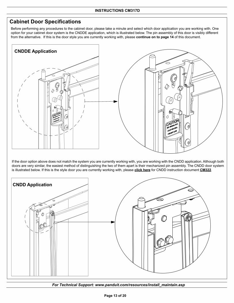
Cabinet Door Specifications
CNDD Application
If the door option above does not match the system you are currently working with, you are working with the CNDD application. Although both doors are very similar, the easiest method of distinguishing the two of them apart is their mechanized pin assembly. The CNDD door system is illustrated below. If this is the style door you are currently working with, please click here for CNDD instruction document CM322.
Page 13 of 20
CNDDE Application
Before performing any procedures to the cabinet door, please take a minute and select which door application you are working with. One option for your cabinet door system is the CNDDE application, which is illustrated below. The pin assembly of this door is visibly different from the alternative. If this is the door style you are currently working with, please continue on to page 14 of this document.

INSTRUCTIONS CM317D
For Technical Support: www.panduit.com/resources/install_maintain.asp
Page 14 of 20
Dual Hinge Door Installation and Removal (CNDDE)To install, lift door and insert lower hinge pin into the bushing in the bottom door support. Orient the door so the top hinge pin is near the top cabinet bushing. Using a pinching action, pull the red finger handle over and down to retract the hinge pin. Release the red finger handle when aligned with the top bushing. To remove, support the door on the open side with one hand while retracting the hinge pin with the other hand as described above.
Upper Hinge Location
Note: For cleaning PANDUIT recommends using ‘SIMPLE GREEN’ all purpose cleaner (or local equivalent) and a lint free cloth
Lower Hinge Location
Caution: Support the weight of the door during removal.

INSTRUCTIONS CM317D
For Technical Support: www.panduit.com/resources/install_maintain.asp
Page 15 of 20
Dual Hinge Door Usage (CNDDE)The dual hinge door has the unique ability to open on either the left or the right side. This allows full access to either side of the cabinet. For safety, the dual hinge door features an interlock system that prevents handles from turning when either side is open. To close a handle that is locked open, press the spring-loaded levers in the top and the bottom corners of the door and turn the handle simultaneously.
Spring Loaded Lever
Spring Loaded LeverSee note below
Note: Depress levers simultaneously to disengage handle interlock.
See note below
Fascia InstallationRemove 3 keyed knockouts and secure the fascia with the 3 screws provided
Important: Note: Do not over tighten. Maximum torque applied should be 20in.-lbs (2.26 N-m).

INSTRUCTIONS CM317D
For Technical Support: www.panduit.com/resources/install_maintain.asp
Door AdjustmentThe cabinet is equipped with a bottom door shoe lift bushing. The purpose of this lift bushing is to provide vertical adjustment within a cabinet's door frame and enable cabinet doors to be adjusted for a consistent fit and function.
Page 16 of 20
The door shoe lift bushing allows field adjustments on the cabinet doors. Loosing the set screw and raising the lift screw, which lifts the door, adjusting the door's fit within a cabinet's door frame.
Dual hinge door
Split Doors
Network Cabinet
Dual hinge door
Exploded View
Lift Screw
BushingSet Screw
Door adjusted by lift bushing maintaining consistent top gaps
Corrected door fit by adjusting opposite side lift screw.Re-tighten set screws when desired fit is achieved
Unleveled cabinet causing insufficient gap between door and door shoe, resulting in rubbing or interference with bottom door shoe
INSTRUCTIONS CM317D
For Technical Support: www.panduit.com/resources/install_maintain.asp
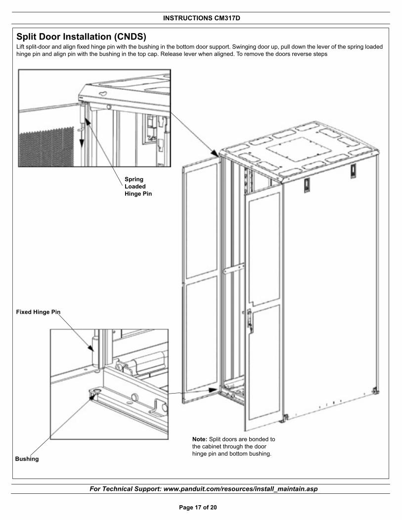
Split Door Installation (CNDS)Lift split-door and align fixed hinge pin with the bushing in the bottom door support. Swinging door up, pull down the lever of the spring loaded hinge pin and align pin with the bushing in the top cap. Release lever when aligned. To remove the doors reverse steps
Bushing
Fixed Hinge Pin
Spring Loaded Hinge Pin
Page 17 of 20
Note: Split doors are bonded to the cabinet through the door hinge pin and bottom bushing.

INSTRUCTIONS CM317D
For Technical Support: www.panduit.com/resources/install_maintain.asp
Side Panel Installation (CNPS)
Page 18 of 20
Mid-Level Center Support Bracket
External Tooth Lock Washer
Remove Paint Masking
Install the mid-level center support bracket using four (4) #12-24 screws and two (2) #12 external tooth lock washers as shown. The lock washers bond the bracket to the cabinet frame.
Install the four (4) spring clips by removing masking from area as shown. Slide spring clip in place until it clips into pilot hole. The spring clips bond the side panel to the cabinet frame. Install side panel as shown on the next page
Spring Clip
Lower Center Support Bracket
Support Tube Assembly
External Tooth Lock Washer
#12-24 Screw
External Tooth Lock Washer
Install the bottom tube support bar assembly using four (4) #12-24 screws and two (2) #12 external tooth lock washers as shown. Adjust assembly as needed to fit side panel squarely in place with cabinet opening. Check around side panel edge for gap consistency. The lock washer bond the bracket to the cabinet.
Install the lower-level center support brace using two (2) #12-24 screws and two (2) #12 external tooth lock washers as shown. Adjust brace to support the bottom tube support bar assembly as needed.The lock washer bond the bracket to the cabinet.
#12-24 Screw
#12-24 Screw
INSTRUCTIONS CM317D
For Technical Support: www.panduit.com/resources/install_maintain.asp
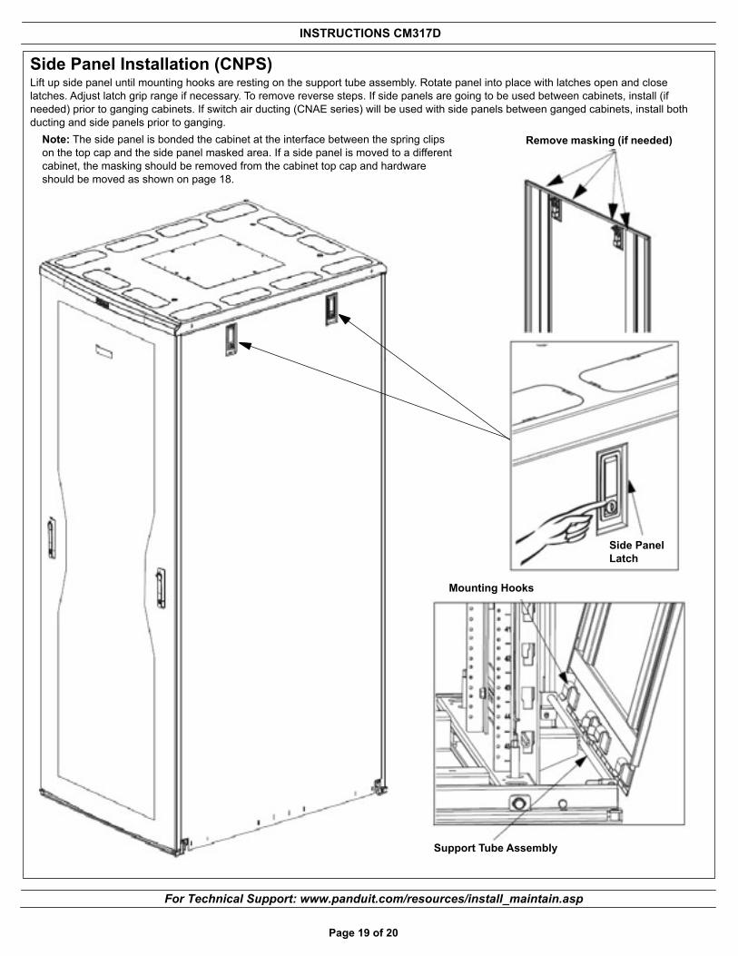
Side Panel Installation (CNPS)Lift up side panel until mounting hooks are resting on the support tube assembly. Rotate panel into place with latches open and close latches. Adjust latch grip range if necessary. To remove reverse steps. If side panels are going to be used between cabinets, install (if needed) prior to ganging cabinets. If switch air ducting (CNAE series) will be used with side panels between ganged cabinets, install both ducting and side panels prior to ganging.
Page 19 of 20
Note: The side panel is bonded the cabinet at the interface between the spring clips on the top cap and the side panel masked area. If a side panel is moved to a different cabinet, the masking should be removed from the cabinet top cap and hardware should be moved as shown on page 18.
Mounting Hooks
Support Tube Assembly
Side Panel Latch
Remove masking (if needed)

INSTRUCTIONS CM317D
For Instructions in Local Languagesand Technical Support:
www.panduit.com/resources/install_maintain.asp
E-mail:[email protected]
Fax:(708)444-6448www.panduit.com
Cable Management InstallationIncluded in the cabinet are (2) sets of cable management fingers sections (10 Right 10 Left). Cable management can be installed where desired by inserting the tabs on the rear of the finger sections in the mounting slots slot located on the four (4) cabinet posts and sliding downward. To remove reverse the process.
Note: The top mounting tab and mounting slot are keyed to allow proper alignment with rack units
Overhead Cable OpeningsCabinet is equipped with multiple covers and knockouts for cable entry. The center top plate can be removed by removing the four (4) #12-24 screws that hold it in place. Knockouts can be removed by cutting the (8) tabs with a wire cutter as shown. Bezels are to be snapped into posi-tion where knockouts have been removed, as shown below. The removable covers can be snapped into overhead cable opening bezels. Grommet edging is provided and is to be used around any knockouts that are removed where bezels and removable covers are not installed. Grommet edging should be cut to 21” in length to cover the edges of each removed knockout.
Page 20 of 20
Removable Cover Overhead Cable Opening Bezel
Overhead Cable Opening Bezel(INSTALLED)
Center Top Plate