cm-150 ca - color kinetics€¦ · chaining of control modules. cm-150 ca product guide 3 cm-150...
TRANSCRIPT

CM-150 CAControl module for large scale architectural and media applications using Flex nodes

CM-150 CA Product Guide2
CM-150 CAControl module for large scale architectural and media applications using Flex nodes
• Supports up to 150 W of power output—CM-150 CA accommodates input and output voltages of 7.5, 12, and 24 volts, so it’s compatible with all current and discontinued Flex family products from Philips Color Kinetics. CM-150 CA supports up to two strands of Flex, with up to 75 nodes per strand.
• Modular and versatile—CM-150 CA is available in a surface mount or DIN rail mount form factor, allowing placement in indoor and outdoor environments, or in your own custom housing. CM-150 CA is compatible with third-party power supplies, so you can purchase the power supplies that work best for your installation.
• Available with 3-wire or 4-wire output—3-wire output is a cost-effective option for shorter runs of up to 7.6 m (25 ft) from the CM-150 CA to your Flex strands. 4-wire output offers more flexibility of placement and can be used in runs of up to 30.5 m (100 ft) from the CM-150 CA to your Flex strands. Longer leader cables are available for custom configurations.
• Integrated test button—CM-150 CA features an onboard button for testing LED nodes that are attached to the control module, even before fully installing your control system. Press this button to instantly show a color wash on attached Flex nodes, confirming that your devices are working just as you expect them to. Press the button again, and your Flex nodes will resume normal operation. On-board indicator LEDs provide visual feedback for normal operation, DMX and Ethernet connection detection, and Ethernet data transmission.
• Compatible with ActiveSite—CM-150 CA is designed to work with ActiveSite from Philips Color Kinetics. With ActiveSite, you can check the devices on your lighting network right from your web browser. And because ActiveSite knows the status of your control module, you can instantly pinpoint a problematic CM-150 CA or attached LED nodes from anywhere in the world.
CM-150 CA delivers integrated data and power to Flex LED luminaires from Philips Color Kinetics. With multiple mounting options, CM-150 CA is the single solution for all large scale installations using Flex nodes, whether color or white. An integrated test button instantly confirms proper functioning of your devices, eliminating costly and time-consuming reinstallation.
DMX and Ethernet input and outputCM-150 CA can accept DMX or Ethernet data. DMX and Ethernet output ports allow for daisy-chaining of control modules.
CM-150 CA Product Guide 3
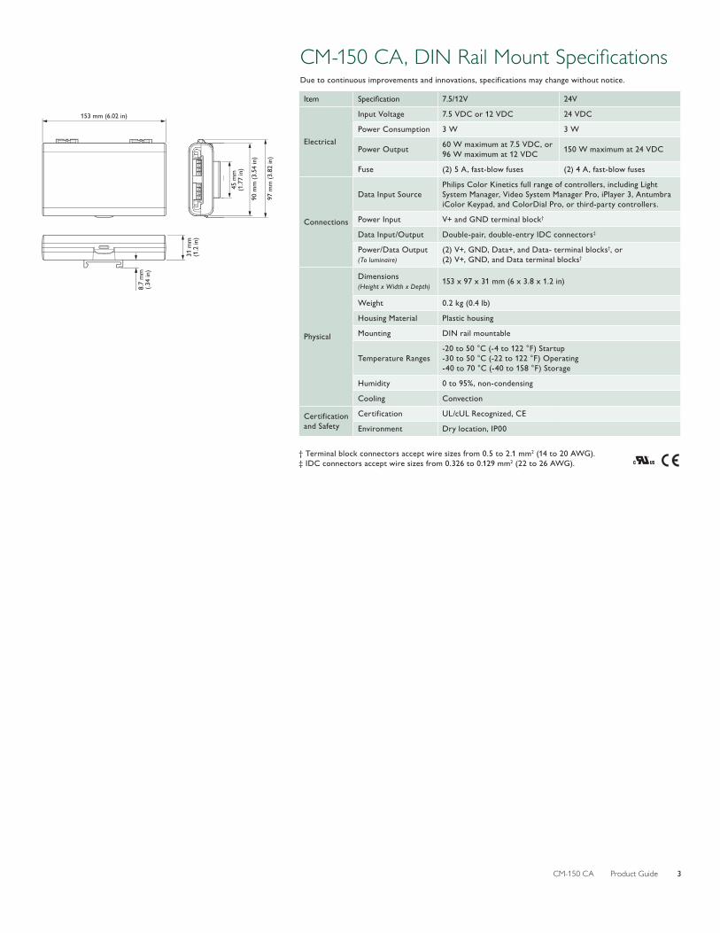
CM-150 CA, DIN Rail Mount SpecificationsDue to continuous improvements and innovations, specifications may change without notice.
Item Specification 7.5/12V 24V
Electrical
Input Voltage 7.5 VDC or 12 VDC 24 VDC
Power Consumption 3 W 3 W
Power Output 60 W maximum at 7.5 VDC, or 96 W maximum at 12 VDC 150 W maximum at 24 VDC
Fuse (2) 5 A, fast-blow fuses (2) 4 A, fast-blow fuses
Connections
Data Input SourcePhilips Color Kinetics full range of controllers, including Light System Manager, Video System Manager Pro, iPlayer 3, Antumbra iColor Keypad, and ColorDial Pro, or third-party controllers.
Power Input V+ and GND terminal block†
Data Input/Output Double-pair, double-entry IDC connectors‡
Power/Data Output (To luminaire)
(2) V+, GND, Data+, and Data- terminal blocks†, or(2) V+, GND, and Data terminal blocks†
Physical
Dimensions (Height x Width x Depth)
153 x 97 x 31 mm (6 x 3.8 x 1.2 in)
Weight 0.2 kg (0.4 lb)
Housing Material Plastic housing
Mounting DIN rail mountable
Temperature Ranges-20 to 50 °C (-4 to 122 °F) Startup-30 to 50 °C (-22 to 122 °F) Operating-40 to 70 °C (-40 to 158 °F) Storage
Humidity 0 to 95%, non-condensing
Cooling Convection
Certification and Safety
Certification UL/cUL Recognized, CE
Environment Dry location, IP00
† Terminal block connectors accept wire sizes from 0.5 to 2.1 mm2 (14 to 20 AWG).‡ IDC connectors accept wire sizes from 0.326 to 0.129 mm2 (22 to 26 AWG).
31 m
m(1
.2 in
)
8.7
mm
(.34
in)
153 mm (6.02 in)
97 m
m (3
.82
in)
90 m
m (3
.54
in)
45 m
m(1
.77
in)

CM-150 CA Product Guide4
CM-150 CA, Surface Mount SpecificationsDue to continuous improvements and innovations, specifications may change without notice.
Item Specification 7.5/12V 24V
Electrical
Input Voltage 7.5 VDC or 12 VDC 24 VDC
Power Consumption 3 W at 7.5 VDC or 12 VDC 3 W at 24 VDC
Power Output 60 W maximum at 7.5 VDC, or 96 W maximum at 12 VDC 150 W maximum at 24 VDC
Fuse (2) 5 A, fast-blow fuses (2) 4 A, fast-blow fuses
Connections
Data Input SourcePhilips Color Kinetics full range of controllers, including Light System Manager, Video System Manager Pro, iPlayer 3, Antumbra iColor Keypad, and ColorDial Pro, or third-party controllers.
Power Input V+ and GND terminal block†
Data Input/Output Double-pair, double-entry IDC connectors‡
Power/Data Output (To luminaire)
(2) three-pin panel mount connectors, or (2) four-pin panel mount connectors
Physical
Dimensions (Height x Width x Depth)
208 x 90 x 39 mm (8.2 x 3.5 x 1.5 in)
Weight 0.7 kg (1.6 lb)
Housing Material Die-cast aluminium, powder-coated finish
Mounting Surface mountable
Temperature Ranges-20 to 50 °C (-4 to 122 °F) Startup-30 to 50 °C (-22 to 122 °F) Operating-40 to 80 °C (-40 to 176 °F) Storage
Humidity 0 to 95%, non-condensing
Cooling Convection
Certification and Safety
Certification UL/cUL, CE
Environment Dry/Damp/Wet Location, IP66
† Terminal block connectors accept wire sizes from 0.5 to 2.1 mm2 (14 to 20 AWG).‡ IDC connectors accept wire sizes from 0.326 to 0.129 mm2 (22 to 26 AWG).
38
.5 m
m(1
.52
in)
8 m
m(0
.31
in)
78 m
m(3
.07
in)
208 mm (8.19 in)
184 mm (7.24 in)
198 mm (7.8 in)
90
mm
(3
.54
in)
CM-150 CA Product Guide 5
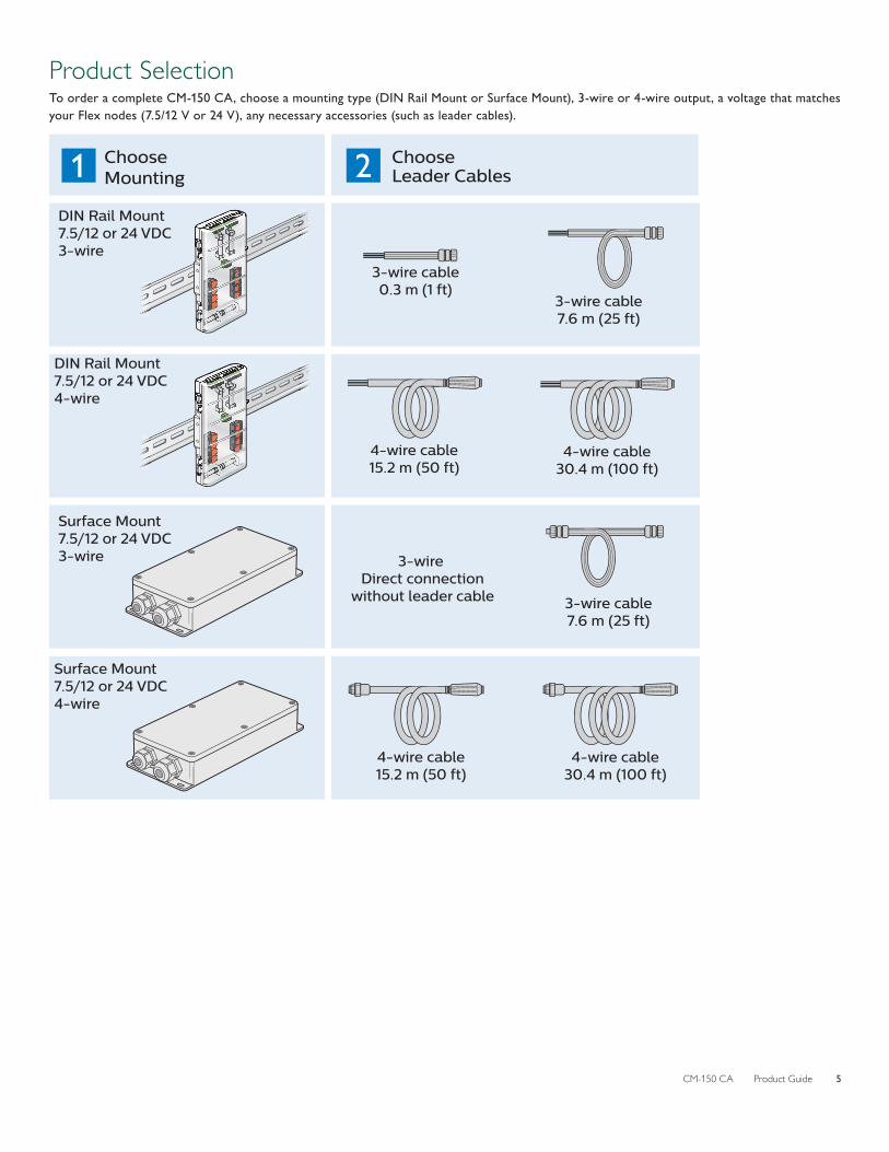
Product SelectionTo order a complete CM-150 CA, choose a mounting type (DIN Rail Mount or Surface Mount), 3-wire or 4-wire output, a voltage that matches your Flex nodes (7.5/12 V or 24 V), any necessary accessories (such as leader cables).
3-wire cable0.3 m (1 ft)
3-wire cable7.6 m (25 ft)
4-wire cable15.2 m (50 ft)
4-wire cable30.4 m (100 ft)
3-wire Direct connection
without leader cable 3-wire cable7.6 m (25 ft)
4-wire cable15.2 m (50 ft)
4-wire cable30.4 m (100 ft)
DIN Rail Mount7.5/12 or 24 VDC4-wire
DIN Rail Mount 7.5/12 or 24 VDC3-wire
Surface Mount7.5/12 or 24 VDC4-wire
Surface Mount 7.5/12 or 24 VDC3-wire
Choose Mounting
Choose Leader Cables

CM-150 CA Product Guide6
Control Module and Leader CablesCM-150 CA is part of a complete system which includes the control module and:
• One or more third-party power supplies
• One leader cable to attach each Flex strand to a control module port
• A Philips Color Kinetics controller, including Light System Manager, Video System Manager Pro, iPlayer 3, Antumbra iColor Keypad, and ColorDial Pro, or a third-party controller.
Control ModulesItem Type Item Number Philips 12NC
CM-150 CA DIN Rail Mount
3-Wire7.5/12V 109-000033-03 912400135769
24V 109-000033-02 912400135768
4-Wire7.5/12V 109-000033-01 912400135767
24V 109-000033-00 912400135766
CM-150 CA Surface Mount
3-Wire7.5/12V 109-000034-03 912400135773
24V 109-000034-02 912400135772
4-Wire7.5/12V 109-000034-01 912400135771
24V 109-000034-00 912400135770
Use Item Number when ordering in North America.
Leader Cables for CM-150 CA, DIN Rail MountItem Type Item Number Philips 12NC
Flex SLX Adapter, 3-Wire 305 mm (1 ft) 108-000084-00 912400135913
Leader Cable, 3-Wire305 mm (1 ft) 108-000081-01 912400136051
7.6 m (25 ft) 108-000081-00 912400135909
Leader Cable, 4-Wire15.2 m (50 ft) 108-000080-01 912400135907
30.5 m (100 ft) 108-000080-02 912400135908
Use Item Number when ordering in North America.
Leader Cables for CM-150 CA, Surface MountItem Type Item Number Philips 12NC
Leader Cable, 3-Wire 7.6 m (25 ft) 108-000083-00 912400135912
Leader Cable, 4-Wire15.2 m (50 ft) 108-000082-01 912400135910
30.5 m (100 ft) 108-000082-02 912400135911
Use Item Number when ordering in North America.
Power Supplies24 V power supply must be ordered separately from Philips or a third party manufacturer. 7.5 V or 12 V power supply must be ordered separately from a third party manufacturer.
Item Item Number Philips 12NC
Power Supply, 320W 24V, 100-277V, IP67, UL, CE, PSE 309-000014-01 912400130539
Power Supply, 320W 24V, 100-277V, IP67, CCC 309-000014-03 912400133656
Power Supply, 320W 24V, 100-277V, IP67, RCM 309-000014-07 912400133660
Use Item Number when ordering in North America.

CM-150 CA Product Guide 7
InstallationCM-150 CA integrates data and power transmission for the Flex family of luminaires. Installation specifics will vary depending on luminaire types, controller, environment (dry or damp/wet).
Owner/User ResponsibilitiesIt is the responsibility of the contractor, installer, purchaser, owner, and user to install, maintain, and operate CM-150 CA in such a manner as to comply with all applicable codes, state and local laws, ordinances, and regulations. Consult with the appropriate electrical inspector to ensure compliance.
Installing in Damp or Wet LocationsWhen installing in damp or wet locations, seal all junction boxes, power supplies, and other devices with electronics-grade RTV silicone sealant so that water or moisture cannot enter or accumulate in any wiring compartments, cables, luminaires, or other electrical parts. You must use suitable outdoor-rated junction boxes when installing in wet or damp locations. Additionally, you must use gaskets, clamps, and other parts required for installation to comply with all applicable local and national codes.
Plan the InstallationTo streamline installation and ensure accurate configuration, start with a layout or a lighting design plan that shows the physical layout of the installation and identifies the locations of all luminaires, CM-150 CA devices, controllers, switches, and cables.
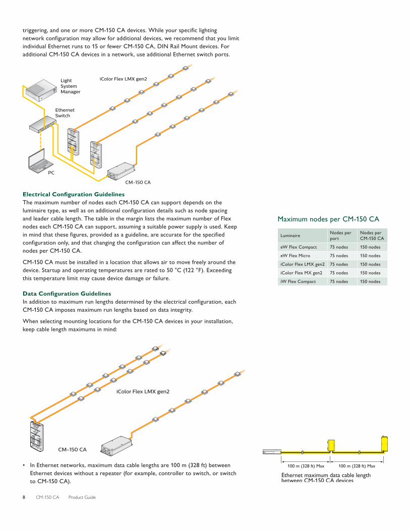
DMX or Ethernet ConfigurationCM-150 CA can be used in either DMX or Ethernet networks. DMX is appropriate for relatively simple installations, or for installations in which groups of lights operate in unison—for example, for accent lighting.
Typical DMX installations with intelligent LED luminaires from Philips Color Kinetics use a controller such as iPlayer 3, a Controller Keypad for turning the lighting system on and off and for triggering light shows, and one or more CM-150 CA devices. CM-150 CA devices can be connected in series to deliver DMX data from a single controller to all connected lights.
iPlayer 3Controller
CM-150 CA
iColor Flex LMX gen2
Because it is not subject to the DMX addressing limitations, Ethernet is the preferred environment for large-scale, color-changing light shows and video displays, both of which require large numbers of unique addresses.
Typical Ethernet installations with Philips Color Kinetics LED luminaires use an Ethernet switch, an Ethernet controller such as Light System Manager or Video System Manager Pro, Antumbra Ethernet Keypads for push-button light show
E Refer to the CM-150 CA Installation Instructions for specific warning and caution statements at www.colorkinetics.com/ls/pds/cm150ca/.
CM-150 CA Product Guide8
triggering, and one or more CM-150 CA devices. While your specific lighting network configuration may allow for additional devices, we recommend that you limit individual Ethernet runs to 15 or fewer CM-150 CA, DIN Rail Mount devices. For additional CM-150 CA devices in a network, use additional Ethernet switch ports.
EthernetSwitch
LightSystemManager
PC
CM-150 CA
iColor Flex LMX gen2
Electrical Configuration GuidelinesThe maximum number of nodes each CM-150 CA can support depends on the luminaire type, as well as on additional configuration details such as node spacing and leader cable length. The table in the margin lists the maximum number of Flex nodes each CM-150 CA can support, assuming a suitable power supply is used. Keep in mind that these figures, provided as a guideline, are accurate for the specified configuration only, and that changing the configuration can affect the number of nodes per CM-150 CA.
CM-150 CA must be installed in a location that allows air to move freely around the device. Startup and operating temperatures are rated to 50 °C (122 °F). Exceeding this temperature limit may cause device damage or failure.
Data Configuration GuidelinesIn addition to maximum run lengths determined by the electrical configuration, each CM-150 CA imposes maximum run lengths based on data integrity.
When selecting mounting locations for the CM-150 CA devices in your installation, keep cable length maximums in mind:
CM-150 CA
iColor Flex LMX gen2
• In Ethernet networks, maximum data cable lengths are 100 m (328 ft) between Ethernet devices without a repeater (for example, controller to switch, or switch to CM-150 CA).
Maximum nodes per CM-150 CA
Luminaire Nodes per port
Nodes per CM-150 CA
eW Flex Compact 75 nodes 150 nodes
eW Flex Micro 75 nodes 150 nodes
iColor Flex LMX gen2 75 nodes 150 nodes
iColor Flex MX gen2 75 nodes 150 nodes
iW Flex Compact 75 nodes 150 nodes
Ethernet maximum data cable length between CM-150 CA devices
100 m (328 ft) Max100 m (328 ft) Max

CM-150 CA Product Guide 9
Select the Right ComponentsTo work with your Flex luminaires, you will need to select the right form factor, leader cable, and third party power supply, as detailed in this section.
Surface Mount or DIN Rail Mount?CM-150 CA is available in either a Surface Mount or a DIN Rail Mount form factor. The DIN Rail Mount form factor is suitable for dry locations only. It can be used indoors, or it can be mounted in a suitable outdoor enclosure. On the other hand, the Surface Mount form factor features an IP66 housing, and can be installed in dry, damp, and wet locations without needing a separate enclosure, allowing greater flexibility of placement.
Third Party Power SupplySelect a third-party power supply that matches the physical and electrical requirements of your lighting installation. Because CM-150 CA passes voltage from the power supply to the attached Flex nodes, it is important that you use a power supply the has the right input voltage, output voltage, and wattage. Refer to the table in the margin to find the correct output voltage for your Flex nodes.
Some power supplies can be shared between multiple control modules. Refer to the specification sheets for your specific control module, Flex strands, and power supply to determine whether this can be done in your lighting installation.
Leader CablesThe type of leader cable you select depends on the distance from the control module to the first Flex node, the form factor of your CM-150 CA, and whether your CM-150 CA has three-wire or four-wire output. The following table shows the available leader cable options for your configuration:
Mounting option Distance to Flex Output to Flex Leader cable options
DIN Rail Mount
≤7.6 m (25 ft) 3-Wire305 mm (1 ft)
7.6 m (25 ft)
>7.6 m (25 ft) 4-Wire15.2 m (50 ft)
30.5 m (100 ft)
Surface Mount
≤7.6 m (25 ft) 3-WireDirect connection without leader cable
7.6 m (25 ft)
>7.6 m (25 ft) 4-Wire15.2 m (50 ft)
30.5 m (100 ft)
Assemble Additional ItemsThe following additional items are required to mount and connect CM-150 CA.
• For installations using the Surface Mount housing, four mounting screws suitable for the mounting surface
• Cat. 5e or better data cable, as required
• Associated cables as listed in Leader Cable Part Numbers table
• Electronics-grade RTV silicone for installations in damp and wet locations
• Screwdrivers, wire strippers, and other tools as needed
• Top hat DIN rail EN 50022, if needed.
Power supply requirements for Flex strands
Luminaire Power supply
eW Flex Compact 24 to 24.5 VDC
eW Flex Micro 24 to 24.5 VDC
iColor Flex LMX gen2 24 to 24.5 VDC
iColor Flex MX gen2 7.5 to 7.7 VDC
iColor Flex SLX 12 to 12.3 VDC
iW Flex Compact 24 to 24.5 VDC

CM-150 CA Product Guide10
Inspect CM-150 CA and AccessoriesCarefully inspect the box containing CM-150 CA and the contents for any damage that may have occurred in transit.
We recommend that you ensure your CM-150 CA devices are running the latest version of the firmware, and update the firmware if necessary, before positioning and mounting the devices. See www.colorkinetics.com/support/downloads/firmware/ for complete information.
Position and Mount CM-150 CAMake sure the power is OFF before mounting and connecting CM-150 CA.
1. Each CM-150 CA is identified by a unique serial number and IP address. The serial number and default IP addresses are located on a label on the CM-150 CA housing. If your installation requires multiple CM-150 CA devices, record the IP addresses (Ethernet) in a layout grid (typically a spreadsheet or list) for easy reference.
2. Assign each device to a position in the lighting design plan.
3. Position each CM-150 CA in its designated mounting location, as detailed below.
Surface Mount InstallationMake sure the mounting surface is flat, suitable for the mounting hardware, and clear of debris and other obstructions.
The overall dimensions of each CM-150 CA, Surface Mount device are 208 mm (8.2 in) wide x 90 mm (3.5 in) deep x 39 mm (1.5 in) high. Make sure the mounting location allows enough space for air to move freely around the device. Be careful not to obstruct or submerge the vent on the CM-150 CA housing.
Use four suitable mounting screws to secure CM-150 CA to the mounting location.
DIN Rail Mount InstallationThe overall dimensions of each CM-150 CA, DIN Rail Mount device are 153 mm (6 in) wide x 97 mm (3.8 in) deep x 31 mm (1.2 in) high. Make sure the mounting location allows enough space for air to move freely around the device.
PCK#: 999-999999-99Item: 9104 036 00112ABCD abcd ABCD abcd 25CHRABCD abc 40CHRDC: 0852 ABC 1234
123400
FFAB0099SN:
MAC: XXXXXXXXXXXX
IP: xx.xxx.xxx.xxx
PCK#: 999-999999-99Item: 9104 036 00112ABCD abcd ABCD abcd 25CHRABCD abc 40CHRDC: 0852 ABC 1234
123400
FFAB0099SN:
MAC: XXXXXXXXXXXX
IP: xx.xxx.xxx.xxx
Included in the box, Surface MountCM-150 CA, Surface Mount2.5 mm (0.25 in) hex wrenchDMX termination pin jumper(2) Spare fuses(2) Connector caps
Included in the box, DIN Rail MountCM-150 CA, DIN Rail MountDMX termination pin jumper(2) Spare fuses, attached inside housing
38
.5 m
m(1
.52
in)
8 m
m(0
.31
in)
78 m
m(3
.07
in)
208 mm (8.19 in)
184 mm (7.24 in)
198 mm (7.8 in)
90
mm
(3
.54
in)
31 m
m(1
.2 in
)
8.7
mm
(.34
in)
153 mm (6.02 in)97
mm
(3.8
2 in
)
90 m
m (3
.54
in)
45 m
m(1
.77
in)
CM-150 CA Product Guide 11
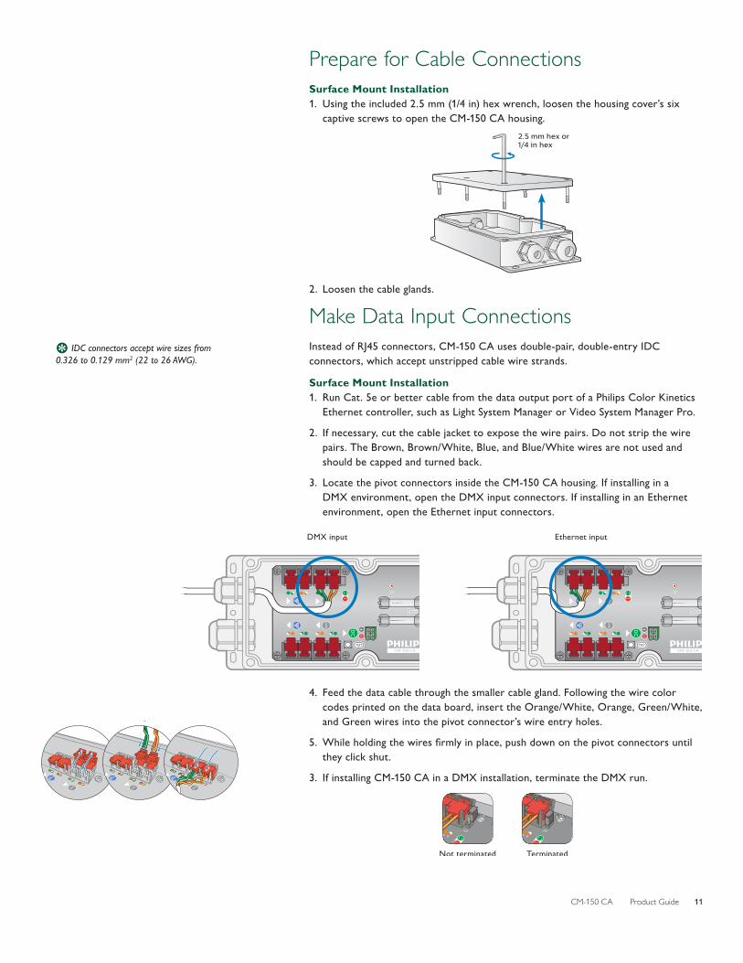
Prepare for Cable ConnectionsSurface Mount Installation1. Using the included 2.5 mm (1/4 in) hex wrench, loosen the housing cover’s six
captive screws to open the CM-150 CA housing.2.5 mm hex or1/4 in hex
2. Loosen the cable glands.
Make Data Input ConnectionsInstead of RJ45 connectors, CM-150 CA uses double-pair, double-entry IDC connectors, which accept unstripped cable wire strands.
Surface Mount Installation1. Run Cat. 5e or better cable from the data output port of a Philips Color Kinetics
Ethernet controller, such as Light System Manager or Video System Manager Pro.
2. If necessary, cut the cable jacket to expose the wire pairs. Do not strip the wire pairs. The Brown, Brown/White, Blue, and Blue/White wires are not used and should be capped and turned back.
3. Locate the pivot connectors inside the CM-150 CA housing. If installing in a DMX environment, open the DMX input connectors. If installing in an Ethernet environment, open the Ethernet input connectors.
DMX input Ethernet input
4. Feed the data cable through the smaller cable gland. Following the wire color codes printed on the data board, insert the Orange/White, Orange, Green/White, and Green wires into the pivot connector’s wire entry holes.
5. While holding the wires firmly in place, push down on the pivot connectors until they click shut.
3. If installing CM-150 CA in a DMX installation, terminate the DMX run.
Not terminated Terminated
E IDC connectors accept wire sizes from 0.326 to 0.129 mm2 (22 to 26 AWG).
CM-150 CA Product Guide12
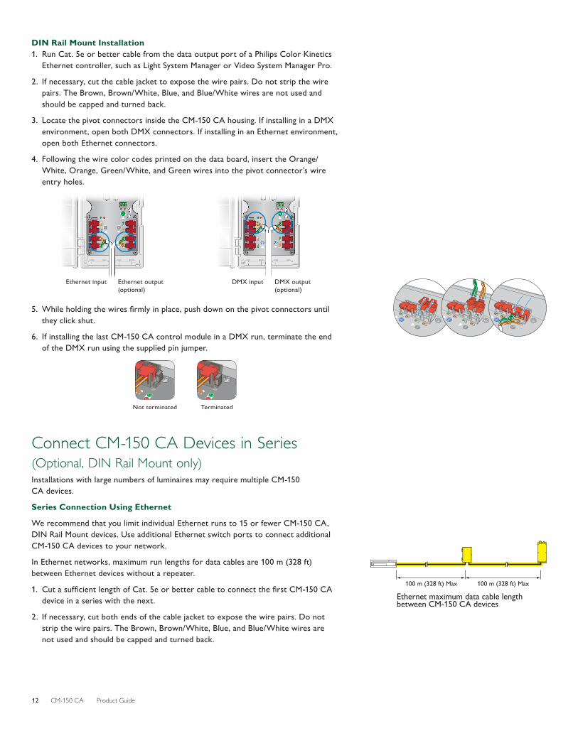
DIN Rail Mount Installation1. Run Cat. 5e or better cable from the data output port of a Philips Color Kinetics
Ethernet controller, such as Light System Manager or Video System Manager Pro.
2. If necessary, cut the cable jacket to expose the wire pairs. Do not strip the wire pairs. The Brown, Brown/White, Blue, and Blue/White wires are not used and should be capped and turned back.
3. Locate the pivot connectors inside the CM-150 CA housing. If installing in a DMX environment, open both DMX connectors. If installing in an Ethernet environment, open both Ethernet connectors.
4. Following the wire color codes printed on the data board, insert the Orange/White, Orange, Green/White, and Green wires into the pivot connector’s wire entry holes.
Ethernet output (optional)
Ethernet input DMX output (optional)
DMX input
5. While holding the wires firmly in place, push down on the pivot connectors until they click shut.
6. If installing the last CM-150 CA control module in a DMX run, terminate the end of the DMX run using the supplied pin jumper.
Not terminated Terminated
Connect CM-150 CA Devices in Series (Optional, DIN Rail Mount only)Installations with large numbers of luminaires may require multiple CM-150 CA devices.
Series Connection Using Ethernet
We recommend that you limit individual Ethernet runs to 15 or fewer CM-150 CA, DIN Rail Mount devices. Use additional Ethernet switch ports to connect additional CM-150 CA devices to your network.
In Ethernet networks, maximum run lengths for data cables are 100 m (328 ft) between Ethernet devices without a repeater.
1. Cut a sufficient length of Cat. 5e or better cable to connect the first CM-150 CA device in a series with the next.
2. If necessary, cut both ends of the cable jacket to expose the wire pairs. Do not strip the wire pairs. The Brown, Brown/White, Blue, and Blue/White wires are not used and should be capped and turned back.
Ethernet maximum data cable length between CM-150 CA devices
100 m (328 ft) Max100 m (328 ft) Max

CM-150 CA Product Guide 13
4. Locate the Ethernet output pivot connectors inside the CM-150 CA housing. Open both pivot connectors.
Ethernet output (optional)
Ethernet input
5. Following the wire color codes printed on the data board, insert the Orange/White, Orange, Green/White, and Green wires into the pivot connector’s wire entry holes.
6. While holding the wires firmly in place, push down on the pivot connectors until they click shut.
7. Run the free end of the cable to the next CM-150 CA device in the series, and make Ethernet data input connections as described in the previous section.
8. Repeat for each CM-150 CA device in the series.
Series Connection Using DMX1. Cut a sufficient length of Cat. 5e cable to connect the first CM-150 CA device in a
series with the next.
2. If necessary, cut both ends of the cable jacket to expose the wire pairs. Do not strip the wire pairs. The Brown, Brown/White, Blue, and Blue/White wires are not used and should be capped and turned back.
4. Locate the DMX output pivot connectors inside the CM-150 CA housing. Open both pivot connectors.
DMX output (optional)
DMX input
5. Following the wire color codes printed on the data board, insert the Orange/White, Orange, Green/White, and Green wires into the pivot connector’s wire entry holes.
6. While holding the wires firmly in place, push down on the pivot connectors until they click shut.
7. Run the free end of the cable to the next CM-150 CA device in the series, and make DMX data input connections as described in the previous section.
8. Repeat for each CM-150 CA device in the series.
9. If installing the last CM-150 CA control module in a DMX run, terminate the end of the DMX run using the supplied pin jumper.
Not terminated Terminated

CM-150 CA Product Guide14
Make DC Power ConnectionsSurface Mount Installation1. Run the power cable through the larger cable gland of the CM-150 CA housing.
Pull at least 127 mm (5 in) of wire into the housing.
2. Strip 5 mm (0.2 in) of insulation from the wires. If using stranded wire, twist each wire tight to secure the wire threads.
3. Locate the DC power 2-wire terminal block connector inside the CM-150 CA housing.
4. Insert the appropriate wire (V+ and ground) in each terminal. Tighten the retaining screws by hand with a screwdriver.
5. Tighten the cable gland around the power cable.
6. Connect the power cable to the power supply.
+V-V
DIN Rail Mount Installation1. Strip 5 mm (0.2 in) of insulation from the wires. If using stranded wire, twist each
wire tight to secure the wire threads.
2. Run the DC power cable through the bottom of the CM-150 CA housing. Pull at least 127 mm (5 in) of wire into the housing.
3. Locate the DC power 2-wire terminal block connector inside the CM-150 CA housing.
4. Insert the appropriate wire (V+ and ground) in each terminal. Tighten the retaining screws by hand with a screwdriver.
6. Connect the power cable to the power supply.
+V-V
5 mm (0.2 in)
E The terminal block connectors accept wire sizes from 0.5 to 2.1 mm2
(14 to 20 AWG).
B Power supply must be isolated type. For 7.5 V Flex, power supply must not exceed 7.7 VDC. For 12 V Flex, power supply must not exceed 12.3 VDC. For 24 V Flex, power supply must not exceed 24.5 VDC.

CM-150 CA Product Guide 15
Make Luminaire Cable ConnectionsFlex strands from Philips Color Kinetics can use a detachable leader cable, or the strands can be connected directly to a CM-150 CA, Surface Mount, 3-Wire control module. Leader cables range from 305 mm (1 ft) to 30.5 m (100 ft), while Flex strands range from 152 mm (6 in) to 3.7 m (12 ft) distance from the connector to the first node.
Surface Mount Installation1. Remove the end caps.
2. Plug leader cable or the Flex strand into the CM-150 CA, and secure the connection.
3-wire output4-wire output
DIN Rail Mount Installation1. Strip 5 mm (0.2 in) of insulation from the wires. If using stranded wire, twist each
wire tight to secure the wire threads.
2. Run a leader cable to the top of the CM-150 CA housing.
3. Locate the luminaire three-wire or four-wire terminal block connectors inside the CM-150 CA housing.
4. Securely install each wire in the appropriate terminal. Tighten the retaining screws by hand with a screwdriver.
4-wire output
V+V-
Data -Data +
3-wire output
V+
GND
Data GND
V+

CM-150 CA Product Guide16
Secure Cover (Surface Mount only)Once you have finished connecting all data and power inputs and outputs, secure the CM-150 CA cover.
1. Seat the cover on the CM-150 CA housing.
2. Using the included 3 mm hex wrench, tighten the housing cover’s six captured screws, as indicated in the diagram to the left. Torque each screw to approximately 1.8 Nm (16 in-lb).
3. Tighten the cable glands around all cables. Do not overtighten.
4. For wet or damp locations, seal all points of entry to prevent water infiltration. Use RTV silicone to seal screw holes and cable glands.
Configuring CM-150 CA with QuickPlay Pro (Optional)You can configure CM-150 CA devices using QuickPlay Pro addressing and configuration software. In Ethernet installations, you can automatically discover all CM-150 CA devices using QuickPlay Pro with a computer connected to your lighting network.
When a CM-150 CA device is connected to your lighting network, the CM-150 CA tab under PDS Configuration becomes active.
RTV Silicone
E You can download QuickPlay Pro from www.colorkinetics.com/support/addressing/.
E For details on standard QuickPlay Pro options for CM-150 CA, refer to the Addressing and Configuration Guide, which you can view or download at www.colorkinetics.com/support/addressing/.

CM-150 CA Product Guide 17
Updating CM-150 CA FirmwareThe CM-150 CA firmware image is periodically updated to improve system performance and functionality. To maximize system performance, make sure your CM-150 CA devices are running the most recent version of the firmware. We recommend that you confirm that your CM-150 CA devices have the most recent version of the firmware before installing them in your lighting network.
Determine CM-150 CA Firmware Version1. You can determine the firmware version that your CM-150 CA devices are
running with a computer and QuickPlay Pro:
In Ethernet installations, connect a computer to the lighting network and run QuickPlay Pro. QuickPlay Pro automatically discovers all connected CM-150 CA devices. Select a device from the Controllers list.
2. If necessary, select a CM-150 CA device from the Controllers list.
The firmware version for the selected CM-150 CA device appears at the top of the QuickPlay Pro window, on the right.
Download CM-150 CA FirmwareIf a more recent version of the CM-150 CA firmware is available, download the firmware file (.hex extension):
1. Visit the Firmware Updater page at www.colorkinetics.com/support/downloads/firmware/ to check for the latest firmware version.
2. If a newer firmware image is available, click the link on the Firmware Updater page to download the firmware file to an accessible location on your computer.
Download CK Firmware UpdaterTo update the firmware image on a CM-150 CA device, you must download and install the CK Firmware Updater application on your computer.
1. Visit the Firmware Updater page at www.colorkinetics.com/support/downloads/firmware/
2. Download the CK Firmware Updater installer.
3. Decompress the file to an accessible location on your computer and open it.
4. Run the installer, and follow the on-screen instructions.
Running a CM-150 CA Firmware Update (Ethernet network)
1. Connect a computer to the lighting network, and run CK Firmware Updater.
2. From the Interface Select list, select Ethernet Controllers.
3. From Device Select list, select CM-150 CA.
4. Click File Select, navigate to the folder to which you downloaded the firmware file (.hex extension), and click Open.
Firmware version number
E You can find more information on Firmware Updater at www.colorkinetics.com/support/downloads/firmware/

CM-150 CA Product Guide18
5. Click Discover. CK Firmware Updater automatically discovers all CM-150 CA devices connected to your lighting network.
6. Select a CM-150 CA device and click PROGRAM.
7. Repeat step 6 for each CM-150 CA device that you want to update.
Recovering from Firmware Update ErrorsIn rare instances, you may experience power or data loss or interruption during the firmware update process. In such cases, a CM-150 CA device may receive an incomplete or corrupt firmware image. You must successfully re-install the firmware image to restore normal CM-150 CA operations.
• In the case of power loss or interruption, the CM-150 CA device retains its assigned IP address, but you are temporarily unable to communicate with the device using that address.
If this happens, enter the reserved IP address 10.1.250.250 in CK Firmware Updater, and re-install the firmware image.
Once the firmware image is successfully installed, you can again communicate with the CM-150 CA device using its assigned IP address.
• In the case of data loss or interruption, you must manually enter the device IP address in CK Firmware Updater to re-install the firmware image.
If you don’t know the assigned IP address, you can cycle power, then use the reserved IP address 10.1.250.250, as described above.

CM-150 CA Product Guide 19
Replacing FusesCM-150 CA has two fuses, each of which protects a Flex strand from excessive current. Two extra fuses are included in with all DIN rail mountable CM-150 CA devices.
Surface Mount Fuse Replacement1. Make sure that the device power is OFF.
2. Using a Phillips screwdriver, unscrew the six screws holding the cover in place. Remove the device cover.
3. Pull the protective cover from the fuse you wish to replace.
4. Remove the fuse from its metal clips.
5. Replace with a new fuse of the same type, as noted in the margin.
6. Replace the protective cover over the fuse and clips.
7. Replace the device cover and secure it with the six cover screws.
DIN Rail Mount Fuse Replacement1. Make sure that the device power is OFF.
2. Open the device cover.
3. Remove the fuse from its metal clips.
4.
Replacement fuses
Replace with a new fuse of the same type, as noted in the margin.
5. Close the device cover.
CM-150 CA fuse types
Control module Fuse type
CM-150 CA, 24V 4 A, 250 V
CM-150 CA, 7.5/12V 5 A, 250 V
E Two replacement fuses are included in the box with the CM-150 CA, Surface Mount.
E Two replacement fuses are located inside the housing of the CM-150 CA, DIN Rail Mount.

Copyright © 2017 Philips Lighting Holding B.V. All rights reserved.Chromacore, Chromasic, CK, the CK logo, Color Kinetics, the Color Kinetics logo, ColorBlast, ColorBlaze, ColorBurst, ColorGraze, ColorPlay, ColorReach, iW Reach, eW Reach, DIMand, EssentialWhite, EvenBalance, eW, iColor, iColor Cove, IntelliWhite, iW, iPlayer, Optibin, and Powercore are either registered trademarks or trademarks of Philips Lighting Holding B.V. in the United States and/or other countries. All other brand or product names are trademarks or registered trademarks of their respective owners. Due to continuous improvements and innovations, specifications may change without notice.
Philips Color Kineticswww.philips.com/colorkinetics
PUB-000163-00 R00 06 Jul 2017