clypso underfloor - warmupus.warmup.co.uk/wp-content/uploads/clypso-installation-manual.pdf ·...
TRANSCRIPT
Clypso Underfloor Heating Installation Manual
Technical Helpline 0845 345 2288
cylpso 2.indd 1 25/04/2014 12:09:03

Product Information
Important Information
Expansion Joint
Laying Patterns
Installation
Pressure Testing Screeding & Floor Covering Information
Warranty
Pressure Test Report
3
4
6
7
Contents
8
9
If you require any help at any stage of the installation please call our helpline :Warmup Technical Helpline 0845 345 2288
2
11
IMPORTANT Please read this manual before attempting to install your underfl oor heating. Incorrect installation will invalidate your warranty. Warmup Plc, accepts no liabilty, expressed or implied, for any loss or consequential damaged suff ered as a result of installations which in any way contravene the instructions that follow.
cylpso 2.indd 2 25/04/2014 12:09:03

3
Product Information - Warmup Clypso Manual
Floor Covering
Screed
Warmup Pipe
Warmup Clip
Warmup Clypso Insulation
Subfl oor with DPM
Perimeter Insulation
1
2
3
4
5
6
7
12
34
5
6
7
System Description
The Warmup Clypso System uses plastic clips to secure the underfl oor heating pipe to the laminated insulation panels. The panels are constructed from either PIR (polyisocyanurate) or expanded polystyrene insulation with a fabric reinforced foil laminated to their surface. The foil on each panel comes with two fl aps, for taping to the adjoining panel, thereby increasing water resistance and separating the insulation layer from the wet screed.
The laminated foil is printed with a grid pattern to make consistent pipe-spacing easier for the installer, especially when required to work around obstacles or a spiral installation pattern. Insulation must comply with Building Regulations in force at the time of approval and BS/EN1264.
The Warmup Clypso System is suitable for almost any fl oor fi nish and in particular where the fl ooring (wood, carpet or vinyl) may be replaced from time to time.
Technical information
The subfl oor below the Warmup Clypso System must be smooth and level, capable of supporting the fl oor zone and imposed loads. A Damp Proof Membrane (DPM) may be required.
The Warmup Clypso Insulation with its woven foil facing will meet both the relevant statutory and thermal effi ciency requirements.
Each insulation board covers an area of 2.88m2 and is available in a choice of thickness from 25 to 100mm and varying compressive strengths, designed by Warmup to meet the project’s exact requirements.
The pipe is clipped to the foil with our barbed clips as per the design layout. The Clypso clip fi xing gun is available to make installations quicker and easier.
Once the system has been installed and pressure tested it should be protected and screeded as soon as possible. Screed is laid to a depth normally between 50 to 75mm.
Output from the system will be designed to meet your requirements taking into account such criteria as fl oor fi nishes.
Components Required
Item Information Warmup Pipe PEX-a - 16mm or
20mm PE-RT/AL /PE-RT - 16mmPE-RT - 16mm
Clypso Insulation Board PIR or EPS Gridded insulation boards available in 25mm -100mm thickness.
Warmup Perimeter Strip Part no. WHS-X-EDGE50
8mm x 150mm x 50m
Warmup Pipe Conduit protectionPart no. WHS-CL-CONDUIT
25mm conduit available in 50m lengths
Clypso clip Fixing GunPart no. Fix-1
Suitable for use with all Warmup clips
Clypso Clips available in 45mm
Warmup Pipe Bend SupportPart no. WHS-P-BEND
Suitable for use with all Warmup pipes
cylpso 2.indd 3 25/04/2014 12:09:04

4
Important Information
Before commencing installation, it is important that a site inspection is performed. You will need to confi rm that all measurements and other requirements on site match your building plans.
Ensure that all subfl oors are the correct depth needed to incorporate the underfl oor heating. Check for anything that might interfere with pipe installation such as concrete walls where they were not expected or changes to the fl oor layout.
Note: A redesign of the layout system may be required if any changes have been made.
InsulationIn accordance with Part ‘L’ of the current Building Regulations, a suitable layer of insulation material should be included within the fl oor construction. It is the responsibility of the Architect or Builder to ensure compliance. The insulation must be installed beneath the under fl oor heating system in order to ensure that any downward heat loss does not exceed 10W/m2, in accordance with BS EN 1264.
DamageInspect the site for possible hazards that could damage the WARMUP pipe, such as nails, staples, materials or tools. Remove any items or potential hazards before installing pipe.
When handling the WARMUP PIPE it is important to protect the pipe from damage.
Uncoiling the pipe DO NOT pull of the coil while it is sitting fl at. It must be unwound from the coil, pulling from the top or the bottom of the coil. This will require one person to hold the pipe off the ground, or the use of an uncoiling device such as the WHUF-UNWINDER.
Bending Radius of the PipeWhen laying the pipe, do not force the pipe into bends. It is easier to lay the pipe with a large radius and then gently pull the pipe to the required bend.The maximum bending radius is 5 times the diameter of the pipe.
KinkingPex- a pipe only Excessive bending of the pipe can cause it to kink, where this occurs fl ow may be obstructed or reduced. Kinked pipe must be repaired. To repair a kink, straighten the pipe and simply heat the area with a hot air gun until the kink disappears.
NOTE: DO NOT use an open fl ame to heat the pipe.
Heat around the pipe to evenly heat the surface. Ensure that you do not overheat the pipe as this will result in damage . The maximum temperature that the PEX-a pipe can withstand is 95°C.
NOTE: Do not try to bend the pipe in the same spot.
Where the pipe is not Pex-a the circuit will need to be replaced with a new pipework.
Cutting the pipeUse a pipe cutter designed for plastic pipe ensuring that there are no burrs on the pipe ends. It is important to achieve a clean cut.
NOTE: If you accidentally damage a Warmup underfl oor heating pipe BEFORE covering it with screed or other coverings, under the Warmup Safetynet guarantee you may return the damaged coil of pipe to Warmup, who will replace the coil FREE OF CHARGE with pipe of the same length and type.
cylpso 2.indd 4 25/04/2014 12:09:04

5
Important Information
Pipe Installation
Install the pipe along outside walls fi rst so that the hottest (supply) water goes to the coldest areas. Pipe should not be installed under appliances such as freezers.
If a pipe circuit is installed under fl oor coverings such as carpet and tile, install pipe under the high R-value area fi rst if possible, as this area will require a higher water temperature.
Keep pipe at least 15 cm from the edges of slabs, walls or other permanent objects in order to prevent damage. This will help to prevent damage to the pipe when these items or fl ooring materials are being installed.
The pipe must not overlap when encased in a Screed as this will reduce the thickness of the Screed possibly leading to damage and/or “hot spots”.
Plan the circuit layout ensuring that pipes can connect to manifolds without crossing each other.Ensure that all circuits have been planned in advance to minimize areas where the pipe passes through expansion joints.
In confi ned areas it may not be possible to use the designed spacing. To avoid cold spots always use tighter spacing and more pipe rather than wider spacing and less pipe.
In the areas where pipes are closer than 10 cm such as near manifolds, if the thickness of the Screed permits, insulate the pipes with conduit to prevent “hot spots”.
Protecting the Warmup Pipe
Pipe Bends
Protection will be required where the Warmup pipe enters the screed.The recommended method for protecting the pipe is the rigid PVC Bend Guide, which holds the pipe in a 90° bend, as well as protecting the pipe from damage.
To install PVC Bend Guides, simply insert the WARMUP pipe through the PVC Bend Guide to the appropriate length, (50-75 cm) .The PVC Bend Guide should be positioned so that the pipe rises straight to the manifold with approximately half the guide within the fl oor.
Conduit Sleeving
Using the Warmup pipe conduit protection sleeve across all construction joints in fl oor. Locations where pipes pass through expansion joints, door frames, walls or where the pipe could get damaged by sharp edges will require protection.
When installing the conduit cut along the length of the conduit and clip onto pipe.
Use the Warmup Pipe Bend Support where it enters the fl oor.
cylpso 2.indd 5 25/04/2014 12:09:05
6
Expansion Joints
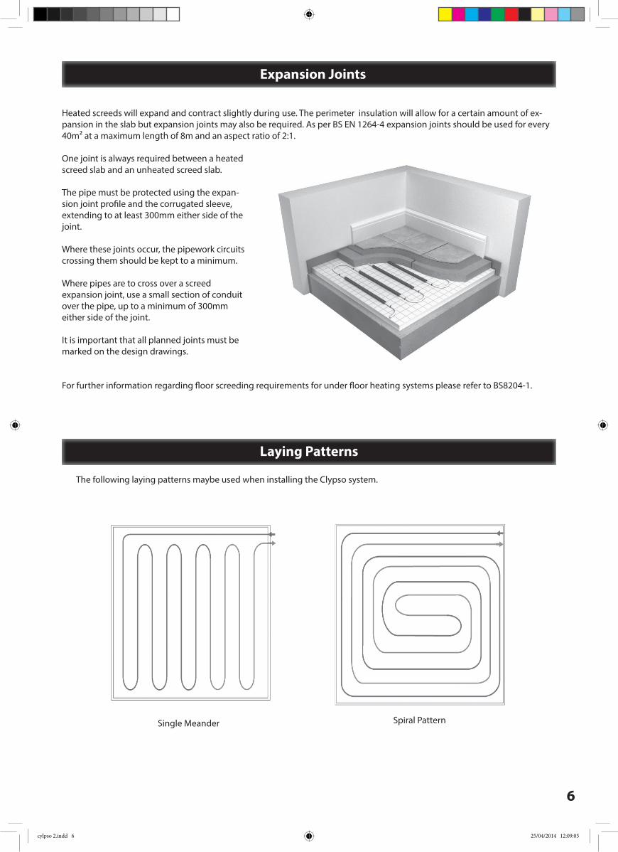
Heated screeds will expand and contract slightly during use. The perimeter insulation will allow for a certain amount of ex-pansion in the slab but expansion joints may also be required. As per BS EN 1264-4 expansion joints should be used for every 40m² at a maximum length of 8m and an aspect ratio of 2:1.
One joint is always required between a heated screed slab and an unheated screed slab.
The pipe must be protected using the expan-sion joint profi le and the corrugated sleeve, extending to at least 300mm either side of the joint.
Where these joints occur, the pipework circuits crossing them should be kept to a minimum.
Where pipes are to cross over a screed expansion joint, use a small section of conduit over the pipe, up to a minimum of 300mm either side of the joint.
It is important that all planned joints must be marked on the design drawings.
For further information regarding fl oor screeding requirements for under fl oor heating systems please refer to BS8204-1.
Laying Patterns
The following laying patterns maybe used when installing the Clypso system.
Spiral Pattern Single Meander
cylpso 2.indd 6 25/04/2014 12:09:05

7
Step 1 Ensure that the installation area is dry and sealed to the elements and that you have a level floor surface.
Step 2 Install the Warmup perimeter strip around the perimeter of the room.
Ensure that the strip is positioned above screed level and fixed using glue or staples. Always ensure that there are no gaps that could allow contact between the screed and the structure.
NOTE: Care must be taken to ensure any damp proof membrane in the wall is not perforated.
Step 3 Lay the Clypso insulation boards over the entire floor area butting the boards up to the perimeter strip. Ensure that the boards are laid with the foil facing up. The Boards should be laid in a brick-work pattern with all the boards butted tightly against each other.
Make sure all joints are be taped together to prevent screed slipping down between the insulation boards.
Fix the The polythene overlap of the perimeter strip to the Clypso board using tape.
Step 4After establishing the area to be covered by the circuit, connect to the manifold holding the pipe at a 90° bend using the Warmup pipe bend support. (see page 5)
Step 5 Using the Clypso clip fixing gun attach the pipes to the board approximately 500mm apart in the desired pattern. Follow the Warmup design for the project. It may be necessary to use more staples on pipe bends . NOTE: If the staples are removed from the tacker sheet, tape over the holes in order to keep the surface water resistant.
Step 6 Locations where pipes pass through expansion joints, door frames, walls or where the pipe could get damaged by sharp edges will require protection.
Using the Warmup pipe Conduit protection cover the pipe. Spilt the sleeving along its length and fix over the pipe.
Step 7Fix pipe bend to the return pipe and connect to the manifold.
Step 8 Complete Steps 4-7 for each circuit.
Warmup® Clypso System - Installation
Prepare the subfl oor
Install the perimeter strip and the Clypso insulation
Fix pipe to the fl oor using the Clypso Clips and Clypso clip fixing gun
Ensure that the clips are fi xed securely
cylpso 2.indd 7 25/04/2014 12:09:06
8
Screeding & Floor Coverings
Pressure Testing
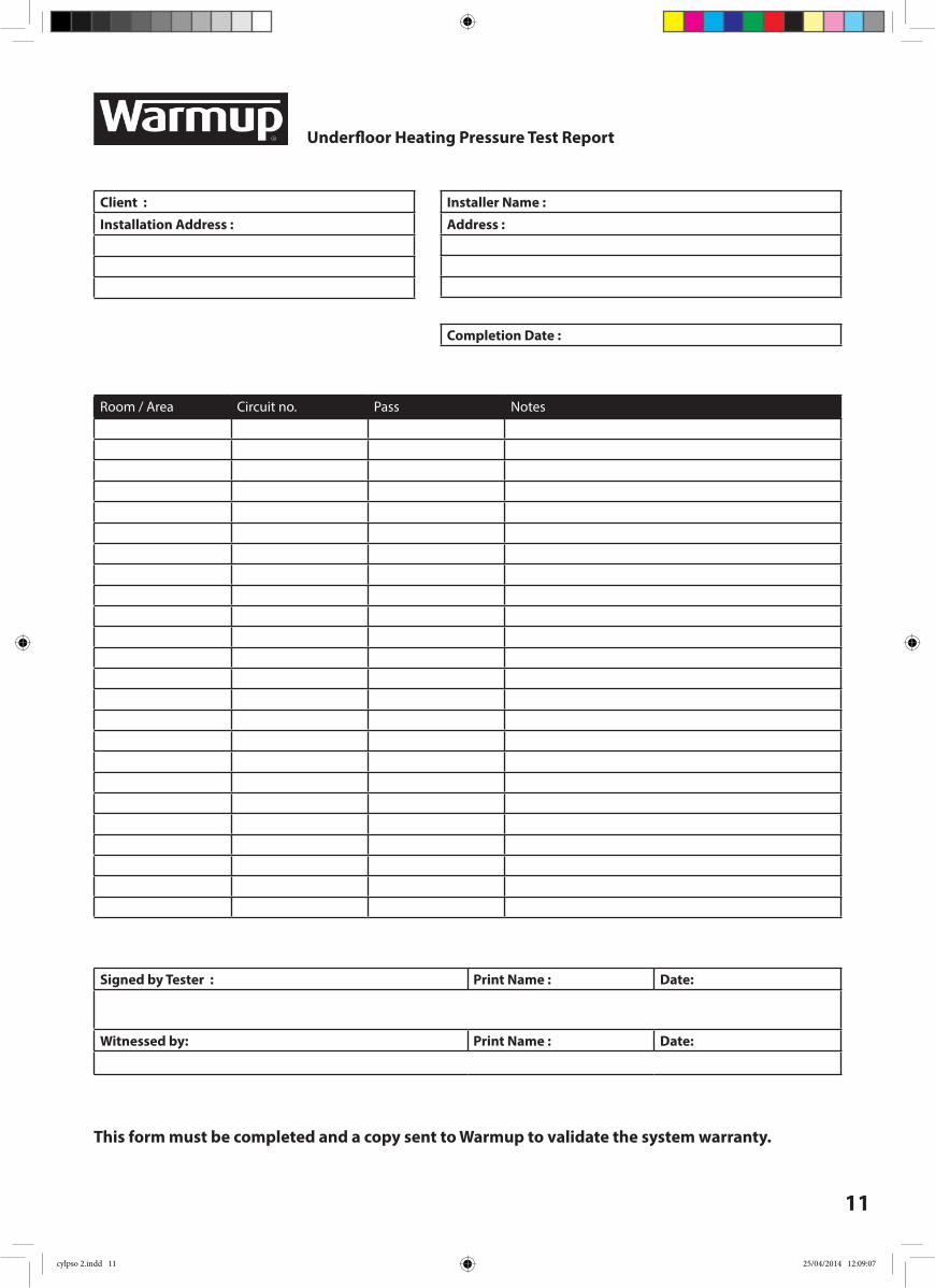
A system pressure test MUST be carried out before the screed has been laid. The system should be fi lled and each circuit purged of air.
Connect the pressure tester to the drain valve and increase the pressure test to 6 bar.
Leave at 6 bar for 1 hr. If the pressure level remains stable record the results on the pressure test certifi cate. If you see that the pressure has dropped you will need to inspect the pipework for damage and fi ttings for proper attachment.
Once the pressure test is complete reduce the system pressure down to 3 bar during screeding to protect the pipework.
Ensure that the screed has fully cured before using the underfl oor heating system as this may reduce the moisture content of the screed. Once the screed has cured and has undergone its fi rst heat cycle, minor micro cracking may occur within the screed. This does NOT aff ect the performance of the screed. However, fi nal fl oor coverings must NOT be laid until the fl oor has cooled down completely.
When installing an underfl oor heating system the thermal conductivity of the fi nal fl oor covering must be considered at the design stage.
Ensure that the fl oor covering is suitable for use with underfl oor heating. It is also important to check that any adhesives used with the fl oor covering are suitable and can tolerate the fl oor surface temperatures.
Timber fl oorsThe important factor is the fl oor moisture content.Timber fl oors can be laid directly over the screed if they have a moisture content of 10-11% which when heated will reduce to 8-9% and may cause a small amount shrinkage.The fl oor will re-absorb some moisture when the heating is not operating and the moisture content will increase to 12-13%.The timber fl oor fi nish should not exceed 18mm in thickness. Timber fl ooring carries a 27°C surface temperature limit.
Carpet The thermal resistance of carpets and underlay is fundamental in attaining good heat transfer. The most popular underlay type is sponge with a waffl e pattern molded into the underside.These allow good heat transfer. Felt and rubber crumb underlay should be avoided. These products can seriously reduce the eff ectiveness of an under fl oor heating system, as they insulate the fl oor surface and prevent heat transfer. For optimal system performance choose an underlay with a maximum TOG value of approximately 0.5. The maximum combined TOG value of carpet should not exceed 2.5 TOG.
Tiles These fl oor coverings work well with under fl oor heating. The Tiles should be laid on a full bed with no air gaps. It is important that the design of the supporting fl oor structure is stable and rigid to prevent cracking. It is recommended that fl exible adhesives and grout be used.
Vinyl Check the fl oor surface temperature indicated by your vinyl supplier for compatibility with under fl oor heating. Vinyl fl ooring carries a 27°C surface temperature limit.
cylpso 2.indd 8 25/04/2014 12:09:06
9
Warmup Plc Limited Warranty – Hydronic Floor Heating Pipe
PLEASE REGISTER YOUR UNDERFLOOR HEATING SYSTEM ONLINE AT: www.warmup.co.ukRegistration can be completed online at www.warmup.co.uk. In the event of a claim, proof of purchase is required, so keep your invoice and receipt - such invoice and receipt should state the type of pipe that has been purchased.
THIS WARRANTY DOES NOT EXTEND TO OTHER COMPONENTS WHICH ARE COVERED BY SEPARATE WARRANTIES. THIS WARRANTY DOES NOT AFFECT YOUR STATUTORY RIGHTS.
Limited Warranty:Warmup® underfloor heating pipe is warranted by WARMUP PLC (“Warmup”) to be free from defects in manufacturing under normal use and maintenance, and is warranted to remain so subject to the limitations and conditions described below.
This warranty period begins on the date of purchase. Registration is confirmed only when confirmation of receipt is forwarded by Warmup PLC.
Warranty Duration
•The Pex-a Underfloor heating pipe is warranted for the LIFETIME of the floor under which it is fitted, except as provided below; your attention is drawn to the exclusions listed and the end of this warranty.
•The Pe-rt Underfloor heating pipe is warranted for a period of 50 years from date of purchase, except as provided below; your attention is drawn to the exclusions listed and the end of this warranty.
•The Pe-rt-Al-Pe-rt Underfloor heating pipe is warranted for a period of 50 years from date of purchase, except as provided below; your attention is drawn to the exclusions listed and the end of this warranty.
Notification of a suspected failure must be received in writing by Warmup within thirty (30) days of the suspected breach. Products believed to be defective must be made available to Warmup for testing and determination of cause. Upon acceptance of any warranty claim, Warmup shall have ninety (90) business days in which to investigate and determine whether it recognises responsibility for any believed defects in material or workmanship and determines the appropriate course of action to be taken.
It is expressly agreed that the sole remedies under this limited warranty shall be at the discretion of Warmup, Plc. to either: issue a refund, repair or replace any article which is proven to be defective. Any and all allowances made to customers for transportation, labour, repairs or all other work, are at the exclusive discretion of Warmup and shall be authorised in writing, in advance, by Warmup. Such cost does not extend to any cost other than direct costs of repair or replacement by Warmup and does not extend to costs of relaying or repairing any floor covering or floor.
The warranty applies to the products identified above only if they:1.are registered with Warmup within 30 days after purchase;2.are selected, designed and installed by a qualified contractor according to installation instructions provided by Warmup which are current as of the applicable Installation Date;3.are connected to appropriate power and water supplies;4.are installed according to all applicable building code requirements;5.are not exposed to pressures and/or temperatures that exceed any limitations printed on the warranted product or in the applicable Warmup product installation manual; 6.remain in their original installed location, such that the floor covering or screed over the product is not damaged, lifted, replaced, repaired or covered with subsequent layers of flooring;7.do not show evidence of accidental damage, misuse, lack of care, tampering, or repair or modification without the prior written approval of Warmup Plc.
Warranty
cylpso 2.indd 9 25/04/2014 12:09:07
10
Without limiting the foregoing, this Warmup Warranty does not apply to:1.damage or repairs required as a consequence of faulty installation, application or abnormal operating conditions;2.damage caused during installation, screeding, laying of the flooring or floor finish, or any other remedial works to the floor that are done post installation;3.damage as a result of floods, fires, winds, lighting, accident, corrosive atmosphere, ultraviolet light or other conditions beyond the control of Warmup Plc;4.use of components or accessories not compatible with this product;5.products installed outside the country of original intended destination when specified by Warmup.6.Normal maintenance as described in the installation and operating manual.7.Parts not supplied or designed by Warmup.8.Any damage caused by frozen or broken heat transfer fluid pipes in the event of equipment failure.9.Changes in the appearance of a product that does not affect its performance.
NOTE: It is important to check that the pipe is pressure tested as specified in the installation manual, prior to screeding or final flooring/finishes being laid.The above Limited Warranty is the full extent of explicit warranties provided by Warmup Plc.
By mutual agreement of all parties, it is agreed that this limited warranty, any claims arising from breach of contract, any breach of warranty, or any other claim arising, shall be governed under the laws of England and Wales. It is expressly understood that Warmup Sales Representatives, Engineers, Distributors, Sub-contractors and Sales and Technical Support Team Members have no authority whatsoever to bind Warmup to any agreement, warranty or remedy of any kind without the express written consent of Warmup Plc.WARMUP PLC. DISCLAIMS:•ANY WARRANTY NOT PROVIDED HEREIN INCLUDING THE IMPLIED WARRANTIES OF MERCHANTABILITY AND/OR FITNESS FOR A PARTICULAR PURPOSE. •ANY STATUTORY OR IMPLIED WARRANTY OF HABITABILITY AS WELL AS ANY RESPONSIBILITY FOR LOSSES, EXPENSES, AND INCONVENIENCES, SPECIAL, INDIRECT, SECONDARY, INCIDENTAL OR CONSEQUENTIAL DAMAGES ARISING FROM POSSESSION OR USE OF THE PRODUCTS AND ITEMS SOLD HEREUNDER.
THIS WARRANTY DOES NOT AFFECT YOUR STATUTORY RIGHTS.
The Warmup Safety Net Installation Guarantee for Underfloor Heating PipeThe Guarantee:If you accidentally damage a Warmup underfloor heating pipe BEFORE covering it with screed or other coverings, you may return the damaged coil of pipe to Warmup, who will replace the coil FREE OF CHARGE with pipe of the same length and type.
Exceptions:1.The Safety Net Guarantee does not cover any other type of damage, misuse, or improper installation due to improper adhesive or subfloor conditions. Limit of one free replacement coil of pipe of a maximum of 125m in length per customer, installer and/or property.2.If at any point Warmup believes the damage to be malicious or intentional, they shall reserve the right to withdraw this guarantee.3.Damage to the pipe that occurs after installing your system is not covered by the Safety Net installation guarantee.4.You must purchase the Warmup Underfloor Heating system from a recognised reseller, and follow all recommended installation procedures written in the, at time of purchase, current Installation Manual. Failure to follow the instructions will result in the revocation of the guarantee.
cylpso 2.indd 10 25/04/2014 12:09:07
11
Room / Area Circuit no. Pass Notes
Installer Name :
Address :
Client :
Installation Address :
Completion Date :
Signed by Tester : Print Name : Date:
Witnessed by: Print Name : Date:
Underfloor Heating Pressure Test Report
This form must be completed and a copy sent to Warmup to validate the system warranty.
cylpso 2.indd 11 25/04/2014 12:09:07

Warmup PLC702 & 704 Tudor Estate
Abbey Road London
NW10 7UW
Web: www.warmup.co.ukEmail: [email protected] Tel: 0845 345 2288
Fax: 0845 345 2299
The WARMUP word and associated logos are trade marks. © Warmup Plc. 2014 – Regd. TM Nos. 1257724, 4409934, 4409926, 5265707. E & OE.V1.0 2014
cylpso 2.indd 12 25/04/2014 12:09:07