clux-c41c - 切替器.net 延長器 共有器 変換器 ev rp us ha n obj c tf y k i d g module...
TRANSCRIPT

CLUX-C41C 4 by 1 HDMI V1.3
Switcher with CEC
Operation Manual
CLUX-C41C

Disclaimers
The information in this manual has been carefully checked and is believed to be accurate. Cypress Technology assumes no responsibility for any infringements of patents or other rights of third parties which may result from its use.Cypress Technology assumes no responsibility for any inaccuracies that may be contained in this document. Cypress also makes no commitment to update or to keep current the information contained in this document.Cypress Technology reserves the right to make improvements to this document and/or product at any time and without notice.
Copyright Notice
No part of this document may be reproduced, transmitted, transcribed, stored in a retrieval system, or any of its part translated into any language or computer file, in any form or by any means - electronic, mechanical, magnetic, optical, chemical, manual, or otherwise - without express written permission and consent from Cypress Technology.
© Copyright 2009 by Cypress Technology.All Rights Reserved.Version 1.0 July 2009

Trademark Acknowledgments
All products or service names mentioned in this document may be trademarks of the companies with which they are associated.
Safety Precautions
Please read all instructions before attempting to unpack or install or operate this equipment, and before connecting the power supply.Please keep the following in mind as you unpack and install this equipment:
Always follow basic safety precautions to reduce the risk of fire, electrical shock and injury to persons.
To prevent fire or shock hazard, do not expose the unit to rain, moisture or install this product near water.
Never spill liquid of any kind on or into this product. Never push an object of any kind into this product through
module openings or empty slots, as you may damage parts. Do not attach the power supply cabling to building surfaces. Do not allow anything to rest on the power cabling or allow it to
be abused by persons walking on it. To protect the equipment from overheating, do not block the
slots and openings in the module housing that provide ventilation.
Version No Date Summary of ChangeV1 20090717 Preliminary Release
Revision History

11112344566678
Table of Contents
1. Introduction …………………………………………................................ 2. Applications............................…………………………………………… 3. Package Contents.............………………………………………………. 4. System Requirements ....................………………………………….….. 5. Features .............................……………………………………………… 6. Specifications ......................................................……………………… 7. Operation Controls and Functions...............…………………....……..
7.1 Front Panel...................……..………..............................…………..7.2 Rear Panel....................……..………..............................…………..
8. Remote Control................................................................................... 9. RS-232 Protocol...................................................................................
9.1 Pin Definitions...................…..………..............................…………..9.2 RS-232 Commands..................………............................…………..
10. Connection and Installation..............................................................

1. IntroductionThis is a high performance HDMI switcher that allows for various HDMI sources to share one HDTV display. This device features CEC control functions and supports deep color, xvYCC and RS-232 control. Simply press one button select your desired HDMI source to display on the HDTV or use remote control to control your sources from a distance. Switching from one HDMI input source to another will no longer be an inconvenience.
2. Applications Multi-sources with one display
Showroom display
Educational presentation
3. Package Contents 4 by 1 HDMI v1.3 Switcher Remote Control (CR-63 with battery) 5V DC Power Supply Adaptor Operation Manual
4. System RequirementsInput source equipments, output displayer with HDMI cables.
1

5. Features HDMI 1.3 and HDCP 1.1 compliant
Supports deep color display RGB/YCbCr 4:4:4 24/30/36 bits
Supports color space YCbCr 4:2:2 16/20/24 bits
Supports high definition audio – Dolby Digital True HD® and DTS-HD®
Signal Enhancement feature allows signal quality improvement afterlong distance transmission
HDMI cable distance test with 1080p/8-bit resolution, the input/outputcan reach up to 15/15 meters. If running at 1080p/12-bit, the input/output can reach at up to 15/6 meters
PC resolution supports: VGA, SVGA, XGA, SXGA, and UXGA (1600 x 1200)HD resolution supports: 480i ~1080p 50/60 and 1080p 24
With remote control function
Supports RS232 operation
Supports CEC control function
Supports xvYCC
2

6. Specifications
Frequency Bandwidth 2.25Gbps(single link)Input Ports 4 x HDMI female ports (Type A connector)Output Ports 1 x RS232
1 x HDMI female port (single link)Color Space YCbCr 4:2:2 16/20/24 bitsDeep Color RGB / YCbCr 4:4:4 24/30/36 bitsESD Protection Human body model: ± 10kV (air-gap discharge)
± 6kV (contact discharge)Input TMDS signal 1.2 Volts (peak-to-peak)Input DDC signal 5 Volts (peak-to-peak, TTL)Power Supply 5V/1AWeight(g) 760Dimensions(mm) 240(W) x 104(D) x 44(H)Chassis Material MetalSilkscreen Color BlackOperating Temperature 0ºC~40ºC / 32ºF ~ 104ºFStorage Temperature -20ºC~60ºC / -4ºF ~ 140ºFRelative Humidity 20%~90% RH (non-condensing)Power Consumption 3.3 W
3

7. Operation Controls and Functions7.1 Front Panel
① Remote control sensor.② Input select indicators: Press the “INPUT” button repeatedly to switch to
your desired input source. The LED that illuminates indicate the corresponding input source is selected.
③ CEC button indicator: When the LED illuminate it means CEC is ON. Press again to switch CEC to bypass mode and the LED will not illuminate which means the CEC function will be terminate.Note: Both input source and output display must support CEC function for
the switcher to properly perform CEC.④ POWER indicator: When power is connected to the device,
the device automatically turns on and the power LED will turn red.Note: To turn ON or switch the device to standby mode, please press the
"POWER" button on the remote control unit.
1 2 3 4
CLUX-C41C4x1 HDMI v1.3 Switcher with CEC
INPUTCECON/Bypass POWER
① ② ③ ④
4
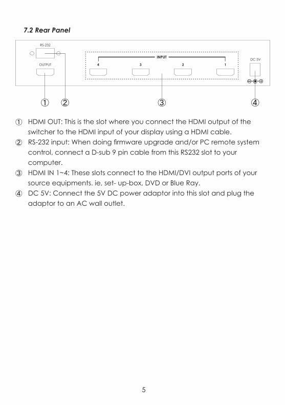
7.2 Rear Panel
① HDMI OUT: This is the slot where you connect the HDMI output of the switcher to the HDMI input of your display using a HDMI cable.
② RS-232 input: When doing firmware upgrade and/or PC remote system control, connect a D-sub 9 pin cable from this RS232 slot to your computer.
③ HDMI IN 1~4: These slots connect to the HDMI/DVI output ports of your source equipments. ie, set- up-box, DVD or Blue Ray.
④ DC 5V: Connect the 5V DC power adaptor into this slot and plug theadaptor to an AC wall outlet.
RS-232
DC 5VOUTPUT
INPUT
4 3 2 1
① ③ ④②
5

8. Remote Control
① Power: This button turns on the unit or set the deviceto standby mode.
② CEC: This button turns on the CEC function of the unit orset it to bypass mode. Please refer to section 6.1 formore details.
③ Input selector: Buttons 1~4 to select the desired inputsources. Buttons 5~8 do not functioning for this model.
9. RS-232 Protocol9.1 Pin Definitions
Baud Rate: 19200 bpsData Bit: 8 bitsParity: NoneStop Bit: 1 bitFlow Chart: None
CR-63
POWERCEC
INPUT
3 4
1 2
5 6
7 8
①
③
②
Switcher Remote ControllerPIN Assignment PIN Assignment1 NC 1 NC2 TxD 2 RxD3 RxD 3 TxD4 NC 4 NC5 GND 5 GND6 NC 6 NC7 NC 7 NC8 NC 8 NC9 NC 9 NC
6

9.2 RS-232 Commands
Notes:1. The command is a combination of characters and digits.2. This combination command code has to be separated by ASCII character
SPACE.3. If the command is legal the unit will reply “OK” message .4. If the command is illegal, the unit will prompt you with a “NG” message.
Command Code Function“I” + “1” PORT 1 ON“I” + “2” PORT 2 ON“I” + “3” PORT 3 ON“I” + “4” PORT 4 ON
“C” + “1” CEC ON“C” + “0” CEC OFF“P” + “1” POWER ON“P” + “0” POWER OFF
“S” REPORT STATE
7

10. Connection and Installation
LCD TV
DVD1 DVD3
DVD2 STB
CR-63
POWERCEC
INPUT
3 4
1 2
5 6
7 8
30°30°
3M 3M7M
8

Acronyms AAcronym Complete TermCEC Consumer Elelctronics ControlDTS Digital Theater SystemHDCP High-bandwith Digital Content ProtectionHDMI High-Definition Multimedia InterfaceHDTV High-Definition TelevisionRGB Red Green BlueSVGA Super Video Graphics ArraySXGA Supper Extended Graphics ArrayUXGA Ultra Extended Graphics ArrayVGA Video Graphics ArrayXGA Extended Graphics Array


20090803 MPM-CLUXC41C

Home page: http://www.cypress.com.twCYPRESS TECHNOLOGY CO., LTD.

CLUX-C61C 6 by 1 HDMI V1.3
Switcher with CEC
Operation Manual
CLUX-C61C

Disclaimers
The information in this manual has been carefully checked and is believed to be accurate. Cypress Technology assumes no responsibility for any infringements of patents or other rights of third parties which may result from its use.Cypress Technology assumes no responsibility for any inaccuracies that may be contained in this document. Cypress also makes no commitment to update or to keep current the information contained in this document.Cypress Technology reserves the right to make improvements to this document and/or product at any time and without notice.
Copyright Notice
No part of this document may be reproduced, transmitted, transcribed, stored in a retrieval system, or any of its part translated into any language or computer file, in any form or by any means - electronic, mechanical, magnetic, optical, chemical, manual, or otherwise - without express written permission and consent from Cypress Technology.
© Copyright 2009 by Cypress Technology.All Rights Reserved.Version 1.0 July 2009

Trademark Acknowledgments
All products or service names mentioned in this document may be trademarks of the companies with which they are associated.
Safety Precautions
Please read all instructions before attempting to unpack or install or operate this equipment, and before connecting the power supply.Please keep the following in mind as you unpack and install this equipment:
Always follow basic safety precautions to reduce the risk of fire, electrical shock and injury to persons.
To prevent fire or shock hazard, do not expose the unit to rain, moisture or install this product near water.
Never spill liquid of any kind on or into this product. Never push an object of any kind into this product through
module openings or empty slots, as you may damage parts. Do not attach the power supply cabling to building surfaces. Do not allow anything to rest on the power cabling or allow it to
be abused by persons walking on it. To protect the equipment from overheating, do not block the
slots and openings in the module housing that provide ventilation.
Version No Date Summary of ChangeV1 20090717 Preliminary Release
Revision History

11112334555678
Table of Contents
1. Introduction …………………………………………................................ 2. Applications............................…………………………………………… 3. Package Contents.............………………………………………………. 4. System Requirements ....................………………………………….….. 5. Features .............................……………………………………………… 6. Specifications ......................................................……………………… 7. Operation Controls and Functions...............…………………....……..
7.1 Front Panel...................……..………..............................…………..7.2 Rear Panel....................……..………..............................…………..
8. Remote Control................................................................................... 9. RS-232 Protocol...................................................................................
9.1 Pin Definitions...................…..………..............................…………..9.2 RS-232 Commands..................………............................…………..
10. Connection and Installation..............................................................

1. IntroductionThis is a high performance HDMI switcher that allows for various HDMI sources to share one HDTV display. This device features CEC control functions and supports deep color, xvYCC and RS-232 control. Simply press one button select your desired HDMI source to display on the HDTV or use remote control to control your sources from a distance. Switching from one HDMI input source to another will no longer be an inconvenience.
2. Applications Multi-sources with one display
Showroom display
Educational presentation
3. Package Contents 6 by 1 HDMI v1.3 Switcher Remote Control (CR-63 with battery) 5V DC Power Supply Adaptor Operation Manual
4. System RequirementsInput source equipments, output displayer with HDMI cables.
1

5. Features HDMI 1.3 and HDCP 1.1 compliant
Supports deep color display RGB/YCbCr 4:4:4 24/30/36 bits
Supports color space YCbCr 4:2:2 16/20/24 bits
Supports high definition audio – Dolby Digital True HD® and DTS-HD®
Signal Enhancement feature allows signal quality improvement afterlong distance transmission
HDMI cable distance test with 1080p/8-bit resolution, the input/outputcan reach up to 15/15 meters. If running at 1080p/12-bit, the input/output can reach at up to 15/6 meters
PC resolution supports: VGA, SVGA, XGA, SXGA, and UXGA (1600 x 1200)HD resolution supports: 480i ~1080p 50/60 and 1080p 24
With remote control function
Supports RS232 operation
Supports CEC control function
Supports xvYCC
2

6. Specifications
Frequency Bandwidth 2.25Gbps(single link)Input Ports 6 x HDMI female ports (Type A connector)Output Ports 1 x RS232
1 x HDMI female port (single link)Color Space YCbCr 4:2:2 16/20/24 bitsDeep Color RGB / YCbCr 4:4:4 24/30/36 bitsESD Protection Human body model: ± 10kV (air-gap discharge)
± 6kV (contact discharge)Input TMDS signal 1.2 Volts (peak-to-peak)Input DDC signal 5 Volts (peak-to-peak, TTL)Power Supply 5V/1AWeight(g) 850Dimensions(mm) 280(W) x 104(D) x 44(H)Chassis Material MetalSilkscreen Color BlackOperating Temperature 0ºC~40ºC / 32ºF ~ 104ºFStorage Temperature -20ºC~60ºC / -4ºF ~ 140ºFRelative Humidity 20%~90% RH (non-condensing)Power Consumption 4.1W
3
2 1 3
6
2
5
1 INPUT POWER
4
HDMI IN CECON/Bypass
xvYCCDeep Color
CECHD Audio
Switcherv1.3CLUX-C61C 6x1 HDMI
① ② ③ ④ ⑤
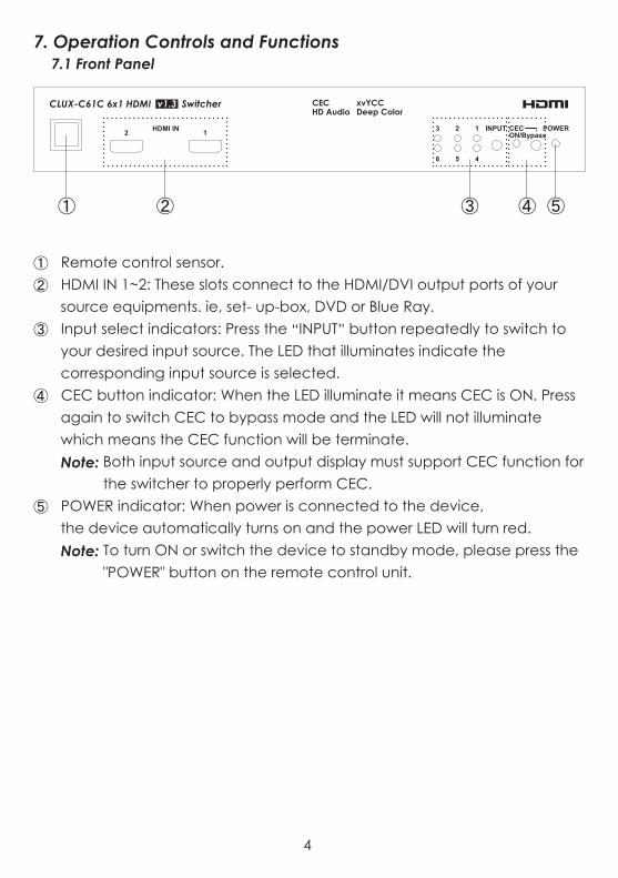
7. Operation Controls and Functions7.1 Front Panel
① Remote control sensor.② HDMI IN 1~2: These slots connect to the HDMI/DVI output ports of your
source equipments. ie, set- up-box, DVD or Blue Ray.③ Input select indicators: Press the “INPUT” button repeatedly to switch to
your desired input source. The LED that illuminates indicate the corresponding input source is selected.
④ CEC button indicator: When the LED illuminate it means CEC is ON. Press again to switch CEC to bypass mode and the LED will not illuminate which means the CEC function will be terminate.Note: Both input source and output display must support CEC function for
the switcher to properly perform CEC.⑤ POWER indicator: When power is connected to the device,
the device automatically turns on and the power LED will turn red.Note: To turn ON or switch the device to standby mode, please press the
"POWER" button on the remote control unit.
4

HDMI OUT 6 5 4 3DC 5V
RS-232
HDMI IN
① ② ③ ④
7.2 Rear Panel
① HDMI OUT: This is the slot where you connect the HDMI output of the switcher to the HDMI input of your display using a HDMI cable.
② RS-232 input: When doing firmware upgrade and/or PC remote system control, connect a D-sub 9 pin cable from this RS232 slot to your computer.
③ HDMI IN 3~6: These slots connect to the HDMI/DVI output ports of your source equipments. ie, set- up-box, DVD or Blue Ray.
④ DC 5V: Connect the 5V DC power adaptor into this slot and plug theadaptor to an AC wall outlet.
5
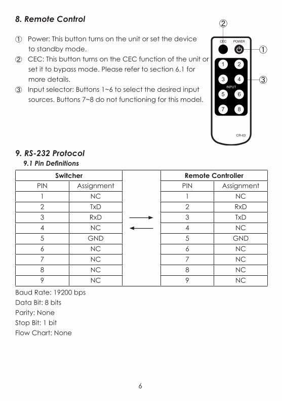
8. Remote Control
① Power: This button turns on the unit or set the deviceto standby mode.
② CEC: This button turns on the CEC function of the unit orset it to bypass mode. Please refer to section 6.1 formore details.
③ Input selector: Buttons 1~6 to select the desired inputsources. Buttons 7~8 do not functioning for this model.
9. RS-232 Protocol9.1 Pin Definitions
Baud Rate: 19200 bpsData Bit: 8 bitsParity: NoneStop Bit: 1 bitFlow Chart: None
CR-63
POWERCEC
INPUT
3 4
1 2
5 6
7 8
①
③
②
Switcher Remote ControllerPIN Assignment PIN Assignment1 NC 1 NC2 TxD 2 RxD3 RxD 3 TxD4 NC 4 NC5 GND 5 GND6 NC 6 NC7 NC 7 NC8 NC 8 NC9 NC 9 NC
6

8.2 RS-232 Command
Note:1. The command is combined with a characters and digits.2. This combination command code has to be separated by ASCII character
SPACE.3. If the command is legal the unit will reply “OK” message .4. If the command is illegal, the unit will reply “NG” message.
Command Code Function“I” + “1” PORT 1 ON“I” + “2” PORT 2 ON“I” + “3” PORT 3 ON“I” + “4” PORT 4 ON“I” + “5” PORT 5 ON“I” + “6” PORT 6 ON
“C” + “1” CEC ON“C” + “0” CEC OFF“P” + “1” POWER ON“P” + “0” POWER OFF
“S” REPORT STATE
7

9. Connection and Installation
CR-63
POWERCEC
INPUT
3 4
1 2
5 6
7 8
30°30°
3M 3M7M
DVD1
DVD2
DVD2
DVD1 DVD3
STB
LCD TV
8

Acronyms AAcronym Complete TermCEC Consumer Elelctronics ControlDTS Digital Theater SystemHDCP High-bandwith Digital Content ProtectionHDMI High-Definition Multimedia InterfaceHDTV High-Definition TelevisionRGB Red Green BlueSVGA Super Video Graphics ArraySXGA Supper Extended Graphics ArrayUXGA Ultra Extended Graphics ArrayVGA Video Graphics ArrayXGA Extended Graphics Array

10

20090703 MPM-CLUXC61C

Home page: http://www.cypress.com.twCYPRESS TECHNOLOGY CO., LTD.
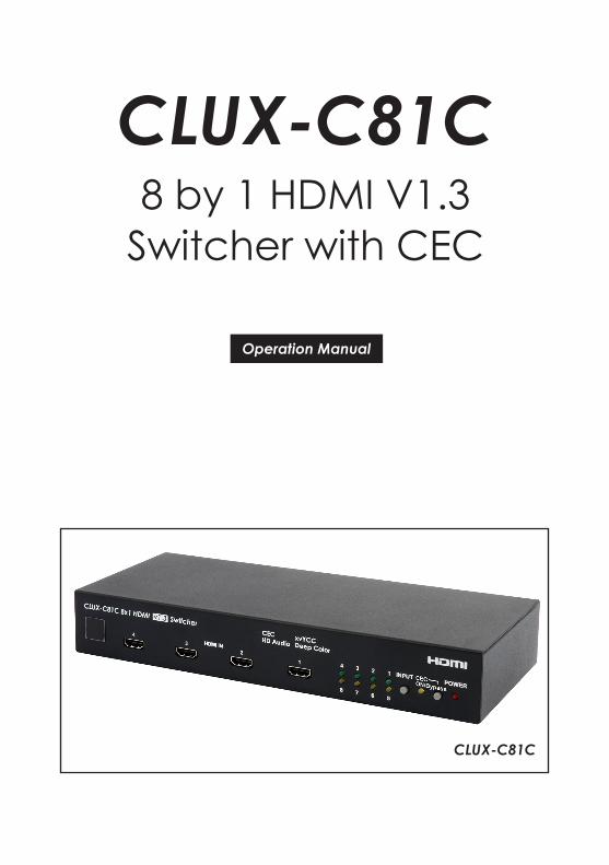
CLUX-C81C 8 by 1 HDMI V1.3
Switcher with CEC
Operation Manual
CLUX-C81C

Disclaimers
The information in this manual has been carefully checked and is believed to be accurate. Cypress Technology assumes no responsibility for any infringements of patents or other rights of third parties which may result from its use.Cypress Technology assumes no responsibility for any inaccuracies that may be contained in this document. Cypress also makes no commitment to update or to keep current the information contained in this document.Cypress Technology reserves the right to make improvements to this document and/or product at any time and without notice.
Copyright Notice
No part of this document may be reproduced, transmitted, transcribed, stored in a retrieval system, or any of its part translated into any language or computer file, in any form or by any means - electronic, mechanical, magnetic, optical, chemical, manual, or otherwise - without express written permission and consent from Cypress Technology.
© Copyright 2009 by Cypress Technology.All Rights Reserved.Version 1.0 July 2009

Trademark Acknowledgments
All products or service names mentioned in this document may be trademarks of the companies with which they are associated.
Safety Precautions
Please read all instructions before attempting to unpack or install or operate this equipment, and before connecting the power supply.Please keep the following in mind as you unpack and install this equipment:
Always follow basic safety precautions to reduce the risk of fire, electrical shock and injury to persons.
To prevent fire or shock hazard, do not expose the unit to rain, moisture or install this product near water.
Never spill liquid of any kind on or into this product. Never push an object of any kind into this product through
module openings or empty slots, as you may damage parts. Do not attach the power supply cabling to building surfaces. Do not allow anything to rest on the power cabling or allow it to
be abused by persons walking on it. To protect the equipment from overheating, do not block the
slots and openings in the module housing that provide ventilation.
Version No Date Summary of ChangeV1 20090717 Preliminary Release
Revision History

Table of Contents
1. Introduction …………………………………………................................ 2. Applications............................…………………………………………… 3. Package Contents.............………………………………………………. 4. System Requirements ....................………………………………….….. 5. Features .............................……………………………………………… 6. Specifications ......................................................……………………… 7. Operation Controls and Functions...............…………………....……..
7.1 Front Panel...................……..………..............................…………..7.2 Rear Panel....................……..………..............................…………..
8. Remote Control................................................................................... 9. RS-232 Protocol...................................................................................
9.1 Pin Definitions...................…..………..............................…………..9.2 RS-232 Commands..................………............................…………..
10. Connection and Installation..............................................................
11112334555678

1. IntroductionThis is a high performance HDMI switcher that allows for various HDMI sources to share one HDTV display. This device features CEC control functions and supports deep color, xvYCC and RS-232 control. Simply press one button select your desired HDMI source to display on the HDTV or use remote control to control your sources from a distance. Switching from one HDMI input source to another will no longer be an inconvenience.
2. Applications Multi-sources with one display
Showroom display
Educational presentation
3. Package Contents 8 by 1 HDMI v1.3 Switcher Remote Control (CR-63 with battery) 5V DC Power Supply Adaptor Operation Manual
4. System RequirementsInput source equipments, output displayer with HDMI cables.
1

5. Features HDMI 1.3 and HDCP 1.1 compliant
Supports deep color display RGB/YCbCr 4:4:4 24/30/36 bits
Supports color space YCbCr 4:2:2 16/20/24 bits
Supports high definition audio – Dolby Digital True HD® and DTS-HD®
Signal Enhancement feature allows signal quality improvement afterlong distance transmission
HDMI cable distance test with 1080p/8-bit resolution, the input/outputcan reach up to 15/15 meters. If running at 1080p/12-bit, the input/output can reach at up to 15/6 meters
PC resolution supports: VGA, SVGA, XGA, SXGA, and UXGA (1600 x 1200)HD resolution supports: 480i ~1080p 50/60 and 1080p 24
With remote control function
Supports RS232 operation
Supports CEC control function
Supports xvYCC
2

6. Specifications
Frequency Bandwidth 2.25Gbps(single link)Input Ports 8 x HDMI female ports (Type A connector)Output Ports 1 x RS232
1 x HDMI female port (single link)Color Space YCbCr 4:2:2 16/20/24 bitsDeep Color RGB / YCbCr 4:4:4 24/30/36 bitsESD Protection Human body model: ± 10kV (air-gap discharge)
± 6kV (contact discharge)Input TMDS signal 1.2 Volts (peak-to-peak)Input DDC signal 5 Volts (peak-to-peak, TTL)Power Supply 5V/1AWeight(g) 850Dimensions(mm) 280(W) x 104(D) x 44(H)Chassis Material MetalSilkscreen Color BlackOperating Temperature 0ºC~40ºC / 32ºF ~ 104ºFStorage Temperature -20ºC~60ºC / -4ºF ~ 140ºFRelative Humidity 20%~90% RH (non-condensing)Power Consumption 4.1W
3

4 3 2 1 4
8
3
7
2
6
1 INPUT POWER
5
HDMI IN
xvYCCDeep Color
CECHD Audio
Switcherv1.3CLUX-C81C 8x1 HDMI
CECON/Bypass
① ② ③ ④ ⑤
7. Operation Controls and Functions7.1 Front Panel
① Remote control sensor.② HDMI IN 1~4: These slots connect to the HDMI/DVI output ports of your
source equipments. ie, set- up-box, DVD or Blue Ray.③ Input select indicators: Press the “INPUT” button repeatedly to switch to
your desired input source. The LED that illuminates indicate the corresponding input source is selected.
④ CEC button indicator: When the LED illuminate it means CEC is ON. Press again to switch CEC to bypass mode and the LED will not illuminate which means the CEC function will be terminate.Note: Both input source and output display must support CEC function for
the switcher to properly perform CEC.⑤ POWER indicator: When power is connected to the device,
the device automatically turns on and the power LED will turn red.Note: To turn ON or switch the device to standby mode, please press the
"POWER" button on the remote control unit.
4

HDMI INHDMI OUT 8 7 6 5DC 5V
RS-232
① ② ③ ④
7.2 Rear Panel
① HDMI OUT: This is the slot where you connect the HDMI output of the switcher to the HDMI input of your display using a HDMI cable.
② RS-232 input: When doing firmware upgrade and/or PC remote system control, connect a D-sub 9 pin cable from this RS232 slot to your computer.
③ HDMI IN 5~8: These slots connect to the HDMI/DVI output ports of your source equipments. ie, set- up-box, DVD or Blue Ray.
④ DC 5V: Connect the 5V DC power adaptor into this slot and plug theadaptor to an AC wall outlet.
5

8. Remote Control
① Power: This button turns on the unit or set the deviceto standby mode.
② CEC: This button turns on the CEC function of the unit orset it to bypass mode. Please refer to section 6.1 formore details.
③ Input selector: Buttons 1~8 to select the desired inputsources.
9. RS-232 Protocol9.1 Pin Definitions
Baud Rate: 19200 bpsData Bit: 8 bitsParity: NoneStop Bit: 1 bitFlow Chart: None
CR-63
POWERCEC
INPUT
3 4
1 2
5 6
7 8
①
③
②
Switcher Remote ControllerPIN Assignment PIN Assignment1 NC 1 NC2 TxD 2 RxD3 RxD 3 TxD4 NC 4 NC5 GND 5 GND6 NC 6 NC7 NC 7 NC8 NC 8 NC9 NC 9 NC
6

9.2 RS-232 Command
Note:1. The command is combined with a characters and digits.2. This combination command code has to be separated by ASCII character
SPACE.3. If the command is legal the unit will reply “OK” message .4. If the command is illegal, the unit will reply “NG” message.
Command Code Function“I” + “1” PORT 1 ON“I” + “2” PORT 2 ON“I” + “3” PORT 3 ON“I” + “4” PORT 4 ON“I” + “5” PORT 5 ON“I” + “6” PORT 6 ON“I” + “7” PORT 7 ON“I” + “8” PORT 8 ON
“C” + “1” CEC ON“C” + “0” CEC OFF“P” + “1” POWER ON“P” + “0” POWER OFF
“S” REPORT STATE
7

10. Connection and Installation
CR-63
POWERCEC
INPUT
3 4
1 2
5 6
7 8
30°30°
3M 3M7M
DVD1 DVD1
DVD2 DVD2
DVD2
DVD1 DVD3
STB
LCD TV
8

Acronyms AAcronym Complete TermCEC Consumer Elelctronics ControlDTS Digital Theater SystemHDCP High-bandwith Digital Content ProtectionHDMI High-Definition Multimedia InterfaceHDTV High-Definition TelevisionRGB Red Green BlueSVGA Super Video Graphics ArraySXGA Supper Extended Graphics ArrayUXGA Ultra Extended Graphics ArrayVGA Video Graphics ArrayXGA Extended Graphics Array
9

10

20090703 MPM-CLUXC81C

Home page: http://www.cypress.com.twCYPRESS TECHNOLOGY CO., LTD.