cloud networking scaling out data center networks white paper cloud networking: scaling out data...
TRANSCRIPT
ARISTA WHITE PAPER
Cloud Networking: Scaling Out Data Center Networks
KEY POINTS OF ARISTA DESIGNS All Arista Universal Cloud Network designs revolve around these nine central design goals:
1. No proprietary protocols or vendor lock-ins. Arista believes in open standards. Our proven reference designs show that proprietary protocols and vendor lock-ins aren’t required to build very large scale-out networks
2. Fewer Tiers is better than More Tiers. Designs with fewer tiers (e.g. a 2-tier Spine/Leaf design rather than 3-tier) decrease cost, complexity, cabling and power/heat. Single-tier Spline network designs don’t use any ports for interconnecting tiers of switches so provide the lowest cost per usable port. A legacy design that may have required 3 or more tiers to achieve the required port count just a few years ago can be achieved in a 1 or 2-tier design.
3. No protocol religion. Arista supports scale-out designs built at layer 2 or layer 3 or hybrid L2/L3 designs with open multi-vendor supported protocols like VXLAN that combine the flexibility of L2 with the scale-out characteristics of L3.
4. Modern infrastructure should be run active/active. Multi chassis Link Aggregation (MLAG) at layer 2 and Equal Cost Multi-Pathing (ECMP) at layer 3 enables infrastructure to be built as active/active with no ports blocked so that networks can use all the links available between any two devices.
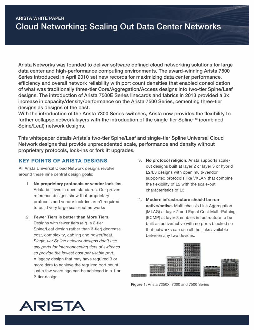
Figure 1: Arista 7250X, 7300 and 7500 Series
Arista Networks was founded to deliver software defined cloud networking solutions for large data center and high-performance computing environments. The award-winning Arista 7500 Series introduced in April 2010 set new records for maximizing data center performance, efficiency and overall network reliability with port count densities that enabled consolidation of what was traditionally three-tier Core/Aggregation/Access designs into two-tier Spine/Leaf designs. The introduction of Arista 7500E Series linecards and fabrics in 2013 provided a 3x increase in capacity/density/performance on the Arista 7500 Series, cementing three-tier designs as designs of the past. With the introduction of the Arista 7300 Series switches, Arista now provides the flexibility to further collapse network layers with the introduction of the single-tier Spline™ (combined Spine/Leaf) network designs. This whitepaper details Arista’s two-tier Spine/Leaf and single-tier Spline Universal Cloud Network designs that provide unprecedented scale, performance and density without proprietary protocols, lock-ins or forklift upgrades.
ARISTA WHITE PAPER CLOUD NETWORKING: SCALING OUT DATA CENTER NETWORKS 2
5. Designs should be agile and allow for flexibility in port speeds. The inflection point when the majority of servers/compute nodes connect at 1000Mb to 10G is between 2013-2015. This in turn drives the requirement for network uplinks to migrate from 10G to 40G and to 100G. Arista switches and reference designs enable that flexibility.
6. Scale-out designs enable infrastructure to start small and evolve over time. A two-way ECMP design can grow from 2-way to 4-way, 8-way, 16-way and as far as a 32-way design. An ECMP design can grow over time without significant up-front capital investment.
7. Large Buffers can be important. Modern Operating Systems, Network Interface Cards (NICs) and scale-out storage arrays make use of techniques such as TCP Segmentation Offload (TSO), GSO and LSO. These techniques are fundamental to reducing the CPU cycles required when servers send large amounts of data. A side effect of these techniques is that an application/ OS/storage that wishes to transmit a chunk of data will offload it to the NIC, which slices the data into segments and puts them on the wire as back-to-back frames at line-rate. If more than one of these is destined to the same output port then microburst congestion occurs. One approach to dealing with bursts is to build a network with minimal oversubscription, overprovisioning links such that they can absorb bursts. Another is to reduce the fan-in of traffic. An alternative approach is to deploy switches with deep buffers to absorb the bursts results in packet drops, which in turn results in lower good-put (useful throughput).
8. Consistent features and OS. All Arista switches use the same Arista EOS. There is no difference in platform, software trains or OS. It’s the same binary image across all switches.
9. Interoperability. Arista switches and designs can interoperate with other networking vendors with no proprietary lock-in.
DESIGN CHOICES – NUMBER OF TIERS
An accepted principle of network designs is that a given design should not be based on the short-term requirements but instead the longer-term requirement of how large a network or network pod may grow over time. Network designs should be based on the maximum number of usable ports that are required and the desired oversubscription ratio for traffic between devices attached to those ports over the longer-term.
If the longer-term requirements for number of ports can be fulfilled in a single switch (or pair of switches in a HA design), then there’s no reason why a single tier spline design should not be used.
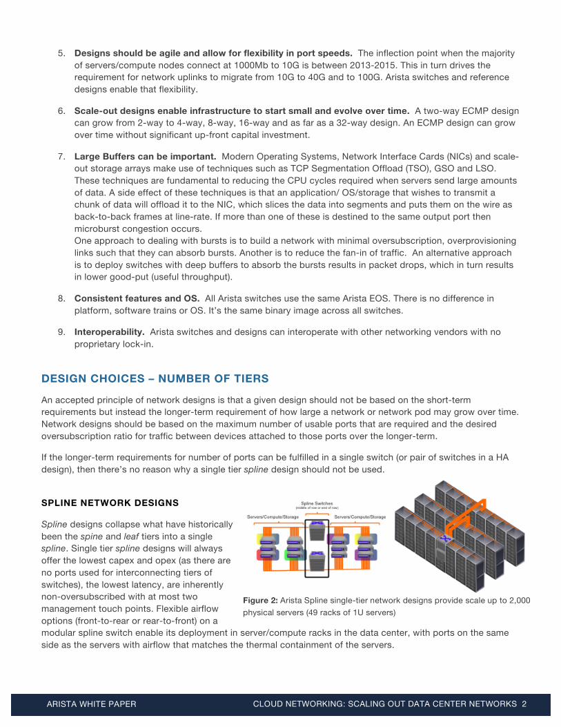
SPLINE NETWORK DESIGNS
Spline designs collapse what have historically been the spine and leaf tiers into a single spline. Single tier spline designs will always offer the lowest capex and opex (as there are no ports used for interconnecting tiers of switches), the lowest latency, are inherently non-oversubscribed with at most two management touch points. Flexible airflow options (front-to-rear or rear-to-front) on a modular spline switch enable its deployment in server/compute racks in the data center, with ports on the same side as the servers with airflow that matches the thermal containment of the servers.
Figure 2: Arista Spline single-tier network designs provide scale up to 2,000 physical servers (49 racks of 1U servers)

ARISTA WHITE PAPER CLOUD NETWORKING: SCALING OUT DATA CENTER NETWORKS 3
Arista 7300 Series (4/8/16 slot modular chassis), Arista 7250X Series (64x40G to 256x10G 2U Fixed switch) and Arista 7050X Series (32x40G to 104x10G+8x40G) switches are ideal for spline network designs providing for 104 to 2048 x 10G ports in a single switch, catering for data centers as small as 3 racks to as large as 49 racks
Table 1: Spline single-tier network designs
Switch Platform Maximum 10G ports
Maximum 40G ports
Maximum 100G Ports
Switch Interface Types
Key Switch Platform Characteristics
Arista 7500 Series
Arista 7508E Arista 7504E
1152 576
288 144
96 48
SFP+/SFP (10G/1G) QSFP+ (40G/4x10G)
MXP (100G/3x40G/12x10G)
Best suited to two-tier Spine/Leaf designs but can be used in spline designs
MXP ports provide most interface speed flexibility
Deep Buffers
VXLAN Hardware Gateway capable
Arista 7300 Series
Arista 7316X Arista 7308X Arista 7304X
2048 1024 512
512 256 128
- - -
RJ45 (100/1000/10G-T)
SFP+/SFP (10G/1G) QSFP+ (40G/4x10G)
Best suited for larger Spline end-of-row / middle of row designs but can be used as spine in two-
tier designs with highest 10G / 40G capacity
RJ45 10GBASE-T enables seamless 100M/1G/10G transition
VXLAN Hardware Gateway capable
Arista 7200 Series Arista 7250X
256
64
-
QSFP+ (40G/4x10G)
Best suited for midsized Spline end-of-row / middle of row designs w/ optical/DAC
connectivity
VXLAN Hardware Gateway capable
Arista 7050X Series Arista 7050QX-32 Arista 7050SX-128
104 104
8 8
- -
SFP+/SFP (10G/1G) QSFP+ (40G/4x10G)
Best suited for small Spline end-of-row / middle of row designs w/ optical/DAC connectivity
VXLAN Hardware Gateway capable
Arista 7050 Series Arista 7050Q-16
Arista 7050S-52/64 Arista 7050T-36/52/64
64
52/64 36/52/64
16 -/4
-/-/4
- - -
RJ45 (100/1000/10G-T)
SFP+/SFP (10G/1G) QSFP+ (40G/4x10G)
Ideal leaf switch in a two-tier Spine/Leaf design
Can fulfill role of small spline switch for <4 rack data center
Arista 7150 Series
Arista 7150S-24/52/64
24/52/64
6/13/16
-
SFP+/SFP (10G/1G) QSFP+ (40G/4x10G)
Ideal leaf switch in a two-tier Spine/Leaf design
Can fulfill role of small spline switch for <4 rack data center
VXLAN Hardware Gateway capable
SPINE/LEAF NETWORK DESIGNS
For designs that don’t fit a single tier spline design then a two-tier spine leaf design is the next logical step. A two-tier design has spine switches at the top tier and leaf switches at the bottom tier with Servers/compute/storage always attached to leaf switches at the top of every rack (or for higher density leaf switches, top of every N racks) and leaf switches uplink to 2 or more spine switches.
Scale out designs start with one pair of spine switches and some quantity of leaf switches. A two-tier leaf/spine network design at 3:1 oversubscription has for 96x10G ports for servers/compute/storage
Figure 3: Arista Spine/Leaf two-tier network designs provide scale in excess of 100,000 physical servers

ARISTA WHITE PAPER CLOUD NETWORKING: SCALING OUT DATA CENTER NETWORKS 4
and 8x40G uplinks per leaf switch (Arista 7050SX-128 – 96x10G : 8x40G uplinks = 3:1 oversubscribed).
Two-tier Spine/Leaf network designs enable horizontal scale-out with the number of spine switches growing linearly as the number of leaf switches grows over time. The maximum scale achievable is a function of the density of the spine switches, the scale-out that can be achieved (this is a function of cabling and number of physical uplinks from each leaf switch) and desired oversubscription ratio.
Either modular or fixed configuration switches can be used for spine switches in a two-tier spine/leaf design however the spine switch choice locks in the maximum scale that a design can grow to. This is shown below in table 2.
Table 2: Maximum scale that is achievable in an Arista two-tier Spine/Leaf design w/ 40G uplinks
Spine Switch Platform
No. Spine Switches
(scale-out) Oversubscription
Spine to Leaf Leaf to Spine Connectivity
Leaf Switch Platform
Design Supports up to <n> Leaf Ports @ 10G
Arista 7504E 2 4
3:1 3:1
4x40G 4x40G
Arista 7050x-64 or Arista 7150S-64
72 leaf x 48x10G = 3,456 x 10G 144 leaf x 48x10G = 6,912 x 10G
Arista 7508E 2 4
3:1 3:1
4x40G 4x40G
Arista 7050x-64 or Arista 7150S-64
144 leaf x 48x10G = 6,912 x 10G 288 leaf x 48x10G = 13,824 x 10G
Arista 7504E 2 4 8
3:1 3:1 3:1
8x40G 8x40G 8x40G
Arista 7050QX-32 or Arista 7050SX-128
36 leaf x 96x10G = 3,456 x 10G 72 leaf x 96x10G = 6,912 x 10G
144 leaf x 96x10G = 13,824 x 10G
Arista 7508E 2 4 8
3:1 3:1 3:1
8x40G 8x40G 8x40G
Arista 7050QX-32 or Arista 7050SX-128
72 leaf x 96x10G = 6,912 x 10G 144 leaf x 96x10G = 13,824 x 10G 288 leaf x 96x10G = 27,648 x 10G
Arista 7508E 2 4 8
16
3:1 3:1 3:1 3:1
16x40G 16x40G 16x40G 16x40G
Arista 7250 36 leaf x 192x10G = 6,912 x 10G 72 leaf x 192x10G = 13,824 x 10G
144 leaf x 192x10G = 27,648 x 10G 288 leaf x 19x10G = 55,296 x 10G
Arista 7508E 2 4 8
16 32
3:1 3:1 3:1 3:1 3:1
32x40G 32x40G 32x40G 32x40G 32x40G
Arista 7304X w/ 7300X-32Q LC
18 leaf x 384x10G = 6,912 x 10G 36 leaf x 384x10G = 13,824 x 10G 72 leaf x 384x10G = 27,648 x 10G
144 leaf x 384x10G = 55,296 x 10G 288 leaf x 384x10G = 110,592 x 10G
Arista 7316X 2 4 8
16 32 64
3:1 3:1 3:1 3:1 3:1 3:1
64x40G 64x40G 64x40G 64x40G 64x40G 64x40G
Arista 7308X w/ 7300X-32Q LC
16 leaf x 768x10G = 12,288 x 10G 32 leaf x 768x10G = 24,576 x 10G 64 leaf x 768x10G = 49,152 x 10G
128 leaf x 768x10G = 98,304 x 10G 256 leaf x 768x10G = 196,608 x 10G 512 leaf x 768x10G = 393,216 x 10G
Arista 7316X 2 4 8
16 32 64
3:1 3:1 3:1 3:1 3:1 3:1
64x40G 64x40G 64x40G 64x40G 64x40G 64x40G
Arista 7316X w/ 7300X-32Q LC
8 leaf x 768x10G = 12,288 x 10G 16 leaf x 768x10G = 24,576 x 10G 32 leaf x 768x10G = 49,152 x 10G 64 leaf x 768x10G = 98,304 x 10G
128 leaf x 768x10G = 196,608 x 10G 256 leaf x 768x10G = 393,216 x 10G
ARISTA WHITE PAPER CLOUD NETWORKING: SCALING OUT DATA CENTER NETWORKS 5
DESIGN CONSIDERATIONS FOR LEAF/SPINE NETWORK DESIGNS
CAPEX COST PER USABLE PORT
A design with more tiers offers higher scalability compared to a design with less tiers. However it trades this off against both higher capital expense (capex) and operational expense (opex). More tiers means more devices, which is more devices to manage as well as more ports used between switches for the fan-out interconnects between switches.
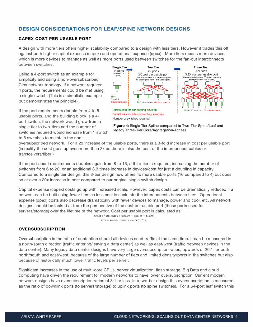
Using a 4-port switch as an example for simplicity and using a non-oversubscribed Clos network topology, if a network required 4 ports, the requirements could be met using a single switch. (This is a simplistic example but demonstrates the principle).
If the port requirements double from 4 to 8 usable ports, and the building block is a 4-port switch, the network would grow from a single tier to two-tiers and the number of switches required would increase from 1 switch to 6 switches to maintain the non-oversubscribed network. For a 2x increase of the usable ports, there is a 3-fold increase in cost per usable port (in reality the cost goes up even more than 3x as there is also the cost of the interconnect cables or transceivers/fiber.)
If the port count requirements doubles again from 8 to 16, a third tier is required, increasing the number of switches from 6 to 20, or an additional 3.3 times increase in devices/cost for just a doubling in capacity. Compared to a single tier design, this 3-tier design now offers 4x more usable ports (16 compared to 4) but does so at over a 20x increase in cost compared to our original single switch design.
Capital expense (capex) costs go up with increased scale. However, capex costs can be dramatically reduced if a network can be built using fewer tiers as less cost is sunk into the interconnects between tiers. Operational expense (opex) costs also decrease dramatically with fewer devices to manage, power and cool, etc. All network designs should be looked at from the perspective of the cost per usable port (those ports used for servers/storage) over the lifetime of the network. Cost per usable port is calculated as: 𝒄𝒐𝒔𝒕 𝒐𝒇 𝒔𝒘𝒊𝒕𝒄𝒉𝒆𝒔 ! 𝒑𝒐𝒘𝒆𝒓 ! 𝒐𝒑𝒕𝒊𝒄𝒔 ! 𝒇𝒊𝒃𝒆𝒓
𝒕𝒐𝒕𝒂𝒍 𝒏𝒐𝒅𝒆𝒔 𝒙 𝒐𝒗𝒆𝒓𝒔𝒖𝒃𝒔𝒄𝒓𝒊𝒑𝒕𝒊𝒐𝒏
OVERSUBSCRIPTION
Oversubscription is the ratio of contention should all devices send traffic at the same time. It can be measured in a north/south direction (traffic entering/leaving a data center) as well as east/west (traffic between devices in the data center). Many legacy data center designs have very large oversubscription ratios, upwards of 20:1 for both north/south and east/west, because of the large number of tiers and limited density/ports in the switches but also because of historically much lower traffic levels per server.
Significant increases in the use of multi-core CPUs, server virtualization, flash storage, Big Data and cloud computing have driven the requirement for modern networks to have lower oversubscription. Current modern network designs have oversubscription ratios of 3:1 or less. In a two-tier design this oversubscription is measured as the ratio of downlink ports (to servers/storage) to uplink ports (to spine switches). For a 64-port leaf switch this
Figure 4: Single Tier Spline compared to Two-Tier Spine/Leaf and legacy Three-Tier Core/Aggregation/Access

ARISTA WHITE PAPER CLOUD NETWORKING: SCALING OUT DATA CENTER NETWORKS 6
equates to 48 ports down to 16 ports up. In contrast a 1:1 design with a 64-port leaf switch would have 32 ports down to 32 up.
A good rule-of-thumb in a modern data center is to start with an oversubscription ratio of 3:1. Features like Arista Latency Analyzer (LANZ) can identify hotspots of congestion before it results in service degradation (seen as packet drops) allowing for some flexibility in modifying the design ratios if traffic is exceeding available capacity.
10G UPLINKS OR 40G UPLINKS FROM LEAF TO SPINE
For a Spine/Leaf network, the uplinks from Leaf to Spine are typically 10G or 40G and can migrate over time from a starting point of 10G (N x 10G) to become 40G (or N x 40G). All Arista 10G ToR switches (except 7050SX-128) offer this flexibility as 40G ports with QSFP+ can operate as 1x40G or 4x10G, software configurable. Additionally the AgilePorts feature on some Arista switches allows a group of four 10G SFP+ ports to operate as a 40G port.
TWO-TIER SPINE/LEAF SCALE-OUT OVER TIME
Scale out designs typically start with two spine switches and some quantity of leaf switches. To give an example of how such a design scales out over time, the following design has Arista 7504E modular switches at the spine and Arista 7050S-64 and 7150S-64 switches at the leaf in a 3:1 oversubscribed design. Each leaf switch provides 48x10G ports for server/compute/storage connectivity and has 16x10G total uplinks to the spine, split into two groups of 8x10G active/active across two spine switches.
With a single DCS-7500E-36Q linecard (36x40G / 144x10G) in each spine switch, the initial network expands to enable connectivity for 18 leaf switches (864 x 10G attached devices @ 3:1 oversubscription end-to-end) as shown in Figure 6.
As more leaf switches are added and the ports on the first linecard of the spine switches are used, a second linecard is added to each chassis and half of the links are moved to the second linecard. The design can grow from 18 leaf switches to 36 leaf switches (1,728 x 10G attached devices @ 3:1 oversubscription end-to-end as shown in Figure 7.
This process repeats a number of times over. If the uplinks between the leaf and spine are at 10G then each uplink can be distributed across 4 ports on 4 linecards in each switch.
The final scale numbers of this design is a function of the port scale/density of the spine switches, the desired oversubscription ratio and the number of spine switches. Provided there are two spine switches the design can be built at layer 2 or layer 3. Final scale for two Arista 7504 spine switches is 72 leaf switches or 3,456 x 10G @ 3:1 oversubscription end-to-end. If the design used a pair of
Figure 5: Leaf switch deployed with 3:1 oversubscription (48x10G down to 4x40G up)
Figure 6: Starting point of a scale-out design: one pair of switches each with a single linecard
Figure 7: First expansion of spine in a scale-out design: second linecard module
ARISTA WHITE PAPER CLOUD NETWORKING: SCALING OUT DATA CENTER NETWORKS 7
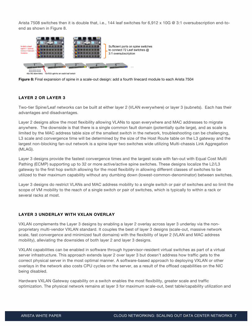
Arista 7508 switches then it is double that, i.e., 144 leaf switches for 6,912 x 10G @ 3:1 oversubscription end-to-end as shown in Figure 8.
Figure 8: Final expansion of spine in a scale-out design: add a fourth linecard module to each Arista 7504
LAYER 2 OR LAYER 3
Two-tier Spine/Leaf networks can be built at either layer 2 (VLAN everywhere) or layer 3 (subnets). Each has their advantages and disadvantages.
Layer 2 designs allow the most flexibility allowing VLANs to span everywhere and MAC addresses to migrate anywhere. The downside is that there is a single common fault domain (potentially quite large), and as scale is limited by the MAC address table size of the smallest switch in the network, troubleshooting can be challenging, L3 scale and convergence time will be determined by the size of the Host Route table on the L3 gateway and the largest non-blocking fan-out network is a spine layer two switches wide utilizing Multi-chassis Link Aggregation (MLAG).
Layer 3 designs provide the fastest convergence times and the largest scale with fan-out with Equal Cost Multi Pathing (ECMP) supporting up to 32 or more active/active spine switches. These designs localize the L2/L3 gateway to the first hop switch allowing for the most flexibility in allowing different classes of switches to be utilized to their maximum capability without any dumbing down (lowest-common-denominator) between switches.
Layer 3 designs do restrict VLANs and MAC address mobility to a single switch or pair of switches and so limit the scope of VM mobility to the reach of a single switch or pair of switches, which is typically to within a rack or several racks at most.
LAYER 3 UNDERLAY WITH VXLAN OVERLAY
VXLAN complements the Layer 3 designs by enabling a layer 2 overlay across layer 3 underlay via the non-proprietary multi-vendor VXLAN standard. It couples the best of layer 3 designs (scale-out, massive network scale, fast convergence and minimized fault domains) with the flexibility of layer 2 (VLAN and MAC address mobility), alleviating the downsides of both layer 2 and layer 3 designs.
VXLAN capabilities can be enabled in software through hypervisor-resident virtual switches as part of a virtual server infrastructure. This approach extends layer 2 over layer 3 but doesn’t address how traffic gets to the correct physical server in the most optimal manner. A software-based approach to deploying VXLAN or other overlays in the network also costs CPU cycles on the server, as a result of the offload capabilities on the NIC being disabled.
Hardware VXLAN Gateway capability on a switch enables the most flexibility, greater scale and traffic optimization. The physical network remains at layer 3 for maximum scale-out, best table/capability utilization and

ARISTA WHITE PAPER CLOUD NETWORKING: SCALING OUT DATA CENTER NETWORKS 8
fastest convergence times. Servers continue to provide NIC CPU offload capability and the VXLAN Hardware Gateway provides layer 2 and layer 3 forwarding, alongside the layer 2 overlay over layer 3 forwarding.
Table 3: Pros/Cons of Layer 2, Layer 3 and Layer 3 with VXLAN designs
Design Type Pros Cons
Layer 2 VLAN everywhere provides most flexibility
MAC mobility enables seamless VM mobility
Single (large) fault domain
Redundant/HA links blocked due to STP
Challenging to extend beyond a pod or data center without extending failure domains
L3 gateway convergence challenged by speed of control plane (ARPs/second)
L3 scale determined by Host route scale @ L3 gateway
Scale can be at most 2-way wide (MLAG active/active)
Maximum Number of VLANs x Ports on a switch limited by Spanning Tree Logical Port Count Scale
Challenging to Troubleshoot
Layer 3 Extends across pods or across data centers
Very large scale-out due to ECMP Very fast convergence/ re-convergence times
VLAN constrained to a single switch
MAC mobility only within a single switch
Layer 3 Underlay with
VXLAN Overlay
VXLAN allows a VLAN to be extended to any switch/device
MAC mobility anywhere there is L3 connectivity
Extends across pods or across data centers
MAC mobility enables seamless VM mobility Very large scale-out due to ECMP
Very fast convergence/re-convergence times
Software/hypervisor virtual switch based VXLAN imposes CPU overhead on host
(hardware VXLAN gateways do not have this trait)
Arista switch platforms with hardware VXLAN gateway capabilities include: Arista 7150 Series, Arista 7050X Series, Arista 7200 Series, Arista 7300X Series and Arista 7500E Series. These platforms support unicast and multicast VXLAN gateway capabilities that can be orchestrated through non-proprietary and open standard APIs such as eAPI OVSDB or configured statically. This open approach to hardware VXLAN gateway capabilities provides end users choice between cloud orchestration platforms without any proprietary vendor lock-in.
FORWARDING TABLE SIZES
Ethernet switching ASICs use a number of forwarding tables for making forwarding decisions: MAC tables (L2), Host Route tables (L3) and Longest Prefix Match (LPM) for L3 prefix lookups. The maximum size of a network that can be built at L2 or L3 is determined by the size of these tables.
Historically a server or host had just a single MAC address and a single IP address. With server virtualization this has become at least 1 MAC address and 1 IP address per virtual server and more than one address/VM if there
ARISTA WHITE PAPER CLOUD NETWORKING: SCALING OUT DATA CENTER NETWORKS 9
are additional virtual NICs (vNICs) defined. Many IT organizations are deploying dual IPv4 / IPv6 stacks (or plan to in the future) and forwarding tables on switches must take into account both IPv4 and IPv6 table requirements.
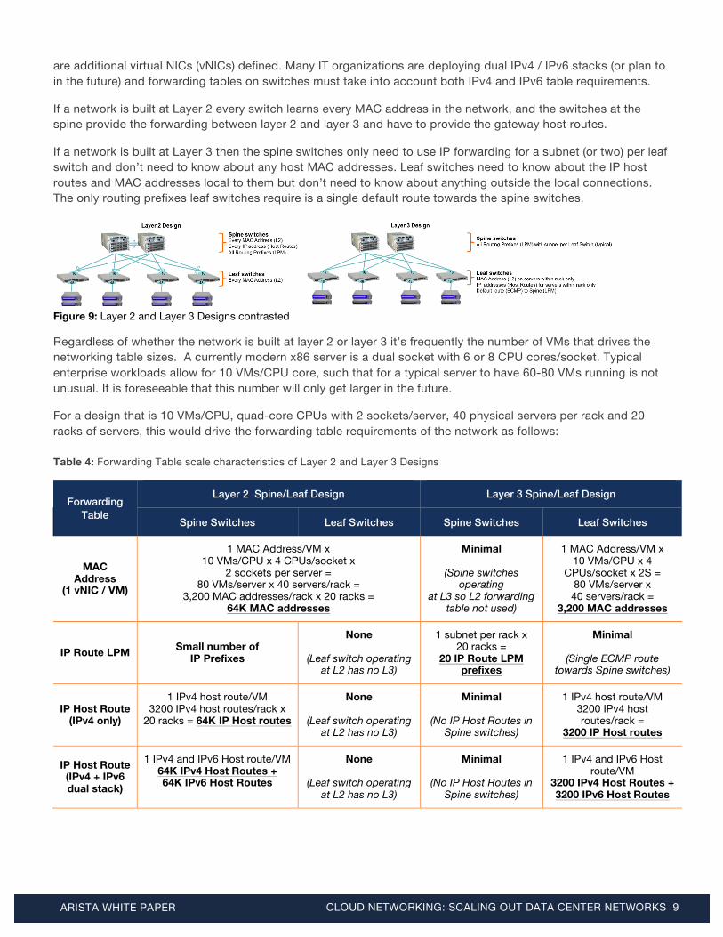
If a network is built at Layer 2 every switch learns every MAC address in the network, and the switches at the spine provide the forwarding between layer 2 and layer 3 and have to provide the gateway host routes.
If a network is built at Layer 3 then the spine switches only need to use IP forwarding for a subnet (or two) per leaf switch and don’t need to know about any host MAC addresses. Leaf switches need to know about the IP host routes and MAC addresses local to them but don’t need to know about anything outside the local connections. The only routing prefixes leaf switches require is a single default route towards the spine switches.
Figure 9: Layer 2 and Layer 3 Designs contrasted
Regardless of whether the network is built at layer 2 or layer 3 it’s frequently the number of VMs that drives the networking table sizes. A currently modern x86 server is a dual socket with 6 or 8 CPU cores/socket. Typical enterprise workloads allow for 10 VMs/CPU core, such that for a typical server to have 60-80 VMs running is not unusual. It is foreseeable that this number will only get larger in the future.
For a design that is 10 VMs/CPU, quad-core CPUs with 2 sockets/server, 40 physical servers per rack and 20 racks of servers, this would drive the forwarding table requirements of the network as follows: Table 4: Forwarding Table scale characteristics of Layer 2 and Layer 3 Designs
Forwarding Table
Layer 2 Spine/Leaf Design Layer 3 Spine/Leaf Design
Spine Switches Leaf Switches Spine Switches Leaf Switches
MAC Address
(1 vNIC / VM)
1 MAC Address/VM x 10 VMs/CPU x 4 CPUs/socket x
2 sockets per server = 80 VMs/server x 40 servers/rack =
3,200 MAC addresses/rack x 20 racks = 64K MAC addresses
Minimal
(Spine switches operating
at L3 so L2 forwarding table not used)
1 MAC Address/VM x 10 VMs/CPU x 4
CPUs/socket x 2S = 80 VMs/server x 40 servers/rack =
3,200 MAC addresses
IP Route LPM Small number of IP Prefixes
None
(Leaf switch operating at L2 has no L3)
1 subnet per rack x 20 racks =
20 IP Route LPM prefixes
Minimal
(Single ECMP route towards Spine switches)
IP Host Route (IPv4 only)
1 IPv4 host route/VM 3200 IPv4 host routes/rack x
20 racks = 64K IP Host routes
None
(Leaf switch operating at L2 has no L3)
Minimal
(No IP Host Routes in Spine switches)
1 IPv4 host route/VM 3200 IPv4 host routes/rack =
3200 IP Host routes
IP Host Route (IPv4 + IPv6 dual stack)
1 IPv4 and IPv6 Host route/VM 64K IPv4 Host Routes + 64K IPv6 Host Routes
None
(Leaf switch operating at L2 has no L3)
Minimal
(No IP Host Routes in Spine switches)
1 IPv4 and IPv6 Host route/VM
3200 IPv4 Host Routes + 3200 IPv6 Host Routes
ARISTA WHITE PAPER CLOUD NETWORKING: SCALING OUT DATA CENTER NETWORKS 10
LAYER 2 SPANNING TREE LOGICAL PORT COUNT SCALE
Despite the common concerns with large layer 2 networks (large broadcast domain, single fault domain, difficult to troubleshoot), one limiting factor often overlooked is the control-plane CPU overhead associated with running the Spanning Tree Protocol on the switches. As a protocol, Spanning Tree is relatively unique in that a failure of the protocol results in a ‘fail open’ state rather than the more modern ‘fail closed’ state. If there is a protocol failure for some reason, there will be a network loop. This characteristic of spanning tree makes it imperative that the switch control plane is not overwhelmed.
With Rapid Per VLAN Spanning Tree (RPVST), the switch maintains multiple independent instances of spanning tree (for each VLAN), sending/receiving BPDUs on ports at regular intervals and changing the port state on physical ports from Learning/Listening/Forwarding/Blocking based on those BPDUs. Managing a large number of non-synchronized independent instances presents a scale challenge unless there is careful design of VLAN trunking. As an example, trunking 4K VLANs on a single port results in the state of each VLAN needing to be tracked individually.
Multiple Spanning Tree Protocol (MSTP) is preferable to RPVST as there are less instances of the spanning tree protocol operating and moving physical ports between states can be done in groups. Even with this improvement layer 2 logical port count numbers still need to be managed carefully.
The individual scale characteristics of switches participating in Spanning Tree varies but the key points to factor into a design are:
• The number of STP Logical Ports supported on a given switch (this is also sometimes referred to as the number of VlanPorts).
• The number of instances of Spanning Tree that are supported if RPVST is being used.
ARISTA TWO-TIER SPINE/LEAF SCALE-OUT DESIGNS
In a two-tier spine/leaf design, every leaf switch attaches to every spine switch. The design can be built at either layer 2 or layer 3, however layer 3 designs scale higher as there can be more than 2 spine switches, and MAC entries and host routes are localized to a given leaf switch or leaf switch pair.
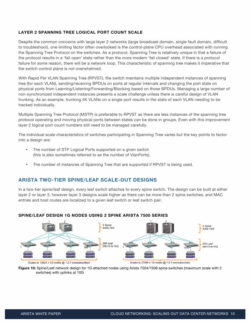
SPINE/LEAF DESIGN 1G NODES USING 2 SPINE ARISTA 7500 SERIES
Figure 10: Spine/Leaf network design for 1G attached nodes using Arista 7504/7508 spine switches (maximum scale with 2
switches) with uplinks at 10G
ARISTA WHITE PAPER CLOUD NETWORKING: SCALING OUT DATA CENTER NETWORKS 11
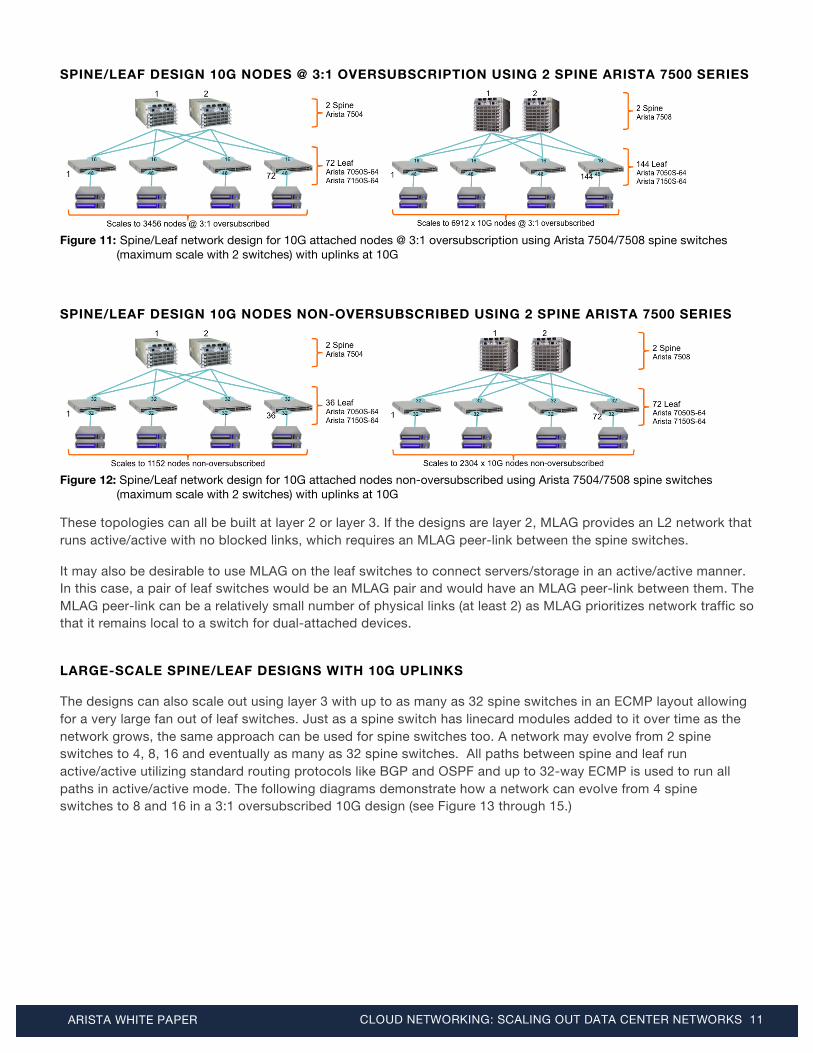
SPINE/LEAF DESIGN 10G NODES @ 3:1 OVERSUBSCRIPTION USING 2 SPINE ARISTA 7500 SERIES
Figure 11: Spine/Leaf network design for 10G attached nodes @ 3:1 oversubscription using Arista 7504/7508 spine switches
(maximum scale with 2 switches) with uplinks at 10G
SPINE/LEAF DESIGN 10G NODES NON-OVERSUBSCRIBED USING 2 SPINE ARISTA 7500 SERIES
Figure 12: Spine/Leaf network design for 10G attached nodes non-oversubscribed using Arista 7504/7508 spine switches
(maximum scale with 2 switches) with uplinks at 10G
These topologies can all be built at layer 2 or layer 3. If the designs are layer 2, MLAG provides an L2 network that runs active/active with no blocked links, which requires an MLAG peer-link between the spine switches.
It may also be desirable to use MLAG on the leaf switches to connect servers/storage in an active/active manner. In this case, a pair of leaf switches would be an MLAG pair and would have an MLAG peer-link between them. The MLAG peer-link can be a relatively small number of physical links (at least 2) as MLAG prioritizes network traffic so that it remains local to a switch for dual-attached devices.
LARGE-SCALE SPINE/LEAF DESIGNS WITH 10G UPLINKS
The designs can also scale out using layer 3 with up to as many as 32 spine switches in an ECMP layout allowing for a very large fan out of leaf switches. Just as a spine switch has linecard modules added to it over time as the network grows, the same approach can be used for spine switches too. A network may evolve from 2 spine switches to 4, 8, 16 and eventually as many as 32 spine switches. All paths between spine and leaf run active/active utilizing standard routing protocols like BGP and OSPF and up to 32-way ECMP is used to run all paths in active/active mode. The following diagrams demonstrate how a network can evolve from 4 spine switches to 8 and 16 in a 3:1 oversubscribed 10G design (see Figure 13 through 15.)

ARISTA WHITE PAPER CLOUD NETWORKING: SCALING OUT DATA CENTER NETWORKS 12
Figure 13: Arista 7504/7508 Spine 4-way ECMP to Arista 64-port 10G Leaf switches @ 3:1 Oversubscription
Figure 14: Arista 7504/7508 Spine 8-way ECMP to Arista 64-port 10G Leaf switches @ 3:1 Oversubscription
Figure 15: Arista 7504/7508 Spine 16-way ECMP to Arista 64-port 10G Leaf switches @ 3:1 Oversubscription
The following diagrams demonstrate how a 1G server design scales with 4-way ECMP (each leaf switch has 4x10G uplinks for 48x1G server/storage connectivity):
Figure 16: Arista 7504/7508 Spine 4-way ECMP to Arista 48x10G Leaf switches @ 1.2:1 Oversubscription

ARISTA WHITE PAPER CLOUD NETWORKING: SCALING OUT DATA CENTER NETWORKS 13
The same design principles can be applied to build a 10G network that is non-oversubscribed. The network size can evolve over time (pay as you grow) with a relatively modest up-front capex investment:
Figure 17: Arista 7504/7508 Spine 4-way ECMP to Arista 64-port 10G Leaf switches non-oversubscribed
Figure 18: Arista 7504/7508 Spine 8-way ECMP to Arista 64-port 10G Leaf switches non-oversubscribed
Figure 19: Arista 7504/7508 Spine 16-way ECMP to Arista 64-port 10G Leaf switches non-oversubscribed
Figure 20: Arista 7504/7508 Spine 32-way ECMP to Arista 64-port 10G Leaf switches non-oversubscribed

ARISTA WHITE PAPER CLOUD NETWORKING: SCALING OUT DATA CENTER NETWORKS 14
LARGE-SCALE DESIGNS WITH 40G UPLINKS
The same simple design principles can be used to build networks with 40G uplinks between spine/leaf instead of 10G uplinks. On Arista switches 40G QSFP+ port can be configured as either 1x40G or 4x10G and using optics breakout to individual 10G links. Many designs can very easily evolve from 10G uplinks to 40G uplinks or support a combination. On Arista switch platforms that support AgilePorts (e.g. Arista 7150S), 4 SFP+ interfaces can be configured into a 40G port allowing further flexibility in selecting uplink speed combinations.
The following diagrams show the maximum scale using 40G uplinks from leaf to spine in a layer 3 ECMP design for 3:1 oversubscribed 10G nodes:
Figure 21: Arista 7504/7508 Spine 4-way ECMP to Arista 48x10G + 4x40G Leaf switches @ 3:1 Oversubscription
OPTICS, CABLING AND TRANSCEIVER CHOICES
There are a variety of transceiver, optics and cabling choices available. SFP+/SFP is the most common transceiver for 10G/1G with support for a wide range of distances: Table 5: SFP+/SFP Transceiver Options
Type Speed Reach Media Notes
10GBASE-CR 10G 0.5m, 1m, 1.5m, 2m, 2.5m, 3m, 5m, 7m
Direct Attach (DAC) CX1 Twinax
Since cable is pre-terminated it comes with transceivers at both ends
fused to a copper cable
10GBASE-SRL 10G 100m (OM3) 150m (OM4) 50µ MMF Optically interoperable with 10GBASE-SR up to 100m
10GBASE-SR 10G 100m (OM3) 150m (OM4) 50µ MMF Optically interoperable with 10GBASE-SRL up to 100m
10GBASE-LRL 10G 1km 9µ SMF Optically interoperable with 10GBASE-LR up to 1km
10GBASE-LR 10G 10km 9µ SMF Optically interoperable with 10GBASE-LRL up to 1km
10GBASE-ER 10G 40km 9µ SMF
10GBASE-ZR 10G 80km 9µ SMF
10GBASE-DWDM 10G 40km/80km 9µ SMF 43 wavelengths available
1000BASE-T 100M/1G 100m Cat5e 100M support available on some switches/transceivers
1000BASE-SX 1G 550m 50µ MMF
1000BASE-LX 1G 10km 9µ SMF
Figure 22: SFP+/SFP Port
ARISTA WHITE PAPER CLOUD NETWORKING: SCALING OUT DATA CENTER NETWORKS 15
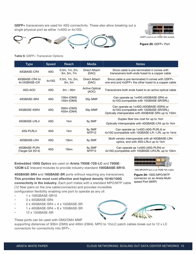
QSFP+ transceivers are used for 40G connectivity. These also allow breaking out a single physical port as either 1x40G or 4x10G:
Table 6: QSFP+ Transceiver Options
Type Speed Reach Media Notes
40GBASE-CR4 40G 0.5m, 1m, 2m, 3m, 5m, 7m
Direct Attach (DAC)
Since cable is pre-terminated it comes with transceivers both ends fused to a copper cable
40GBASE-CR4 to 4x10GBASE-CR 4x10G 0.5m, 1m, 2m,
3m, 5m Direct Attach
(DAC) Since cable is pre-terminated it comes with QSFP+
one end and 4xSFP+ the other fused to a copper cable
40G-AOC 40G 3m – 30m Active Optical (AOC) Transceivers both ends fused to an active optical cable
40GBASE-SR4 40G 100m (OM3) 150m (OM4) 50µ MMF Can operate as 1x40G (40GBASE-SR4) or
4x10G (compatible with 10GBASE-SR/SRL)
40GBASE-XSR4 40G 300m (OM3) 450m (OM4) 50µ MMF
Can operate as 1x40G (40GBASE-XSR4) or 4x10G (compatible with 10GBASE-SR/SRL)
Optically interoperable with 40GBASE-SR4 up to 150m
40GBASE-LRL4 40G 1km 9µ SMF Duplex fiber low cost for up to 1km
Optically interoperable with 40GBASE-LR4 up to 1km
40G-PLRL4 40G 1km 9µ SMF MTP12
Can operate as 1x40G (40G-PLRL4) or 4x10G (compatible with 10GBASE-LR / LRL up to 1km)
40GBASE-LR4 40G 10km 9µ SMF Multi-vendor interoperable with all 40GBASE-LR4 optics, and with 40G-LRL4 up to 1km
40GBASE-PLR4 (Target Q4 2014) 40G 10km 9µ SMF
MTP12 Can operate as 1x40G (40G-PLR4) or
4x10G (compatible with 10GBASE-LR/LRL up to 10km
Embedded 100G Optics are used on Arista 7500E-72S-LC and 7500E-12CM-LC linecard modules to provide industry-standard 100GBASE-SR10,
40GBASE-SR4 and 10GBASE-SR ports without requiring any transceivers. This provides the most cost effective and highest density 10/40/100G connectivity in the industry. Each port mates with a standard MPO/MTP cable (12 fiber pairs on the one cable/connector) and provides incredible configuration flexibility enabling one port to operate as any of: • 1 x 100GBASE-SR10 • 3 x 40GBASE-SR4 • 2 x 40GBASE-SR4 + 4 x 10GBASE-SR • 1 x 40GBASE-SR4 + 8 x 10GBASE-SR • 12 x 10GBASE-SR
These ports can be used with OM3/OM4 MMF supporting distances of 300m (OM3) and 400m (OM4). MPO to 12xLC patch cables break out to 12 x LC connectors for connectivity into SFP+.
Figure 23: QSFP+ Port
Figure 24: 100G MPO/MTP connector on an Arista Multi-speed Port (MXP)

ARISTA WHITE PAPER CLOUD NETWORKING: SCALING OUT DATA CENTER NETWORKS 16
Arista AgilePorts on some switches can use a group of 4 or 10 SFP+ ports to create an industry-standard 40GBASE-SR4 or 100GBASE-SR10. This provides additional flexibility in how networks can grow and evolve from 10G to 40G and 100G while providing increased flexibility in terms of distances supported. ARISTA EOS FOUNDATION FEATURES THAT ENABLE THESE DESIGNS
Arista’s scale-out cloud network designs are underpinned on a number of foundation features of Arista’s award-winning Extensible Operating System:
MULTI CHASSIS LINK AGGREGATION (MLAG)
MLAG enables devices to be attached to a pair of Arista switches (an MLAG pair) with all links running active/active. MLAG eliminates bottlenecks, provides resiliency and enables layer 2 links to operate active/active without wasting 50% of the bandwidth as is the case with STP blocked links. L3 Anycast Gateway (Virtual ARP / VARP) with MLAG enables the L3 gateway to operate in active/active mode without the overhead of protocols like HSRP or VRRP.
To a neighboring device, MLAG behaves the same as standard link aggregation (LAG) and can run either with Link Aggregation Control Protocol (LACP) (formerly IEEE 802.3ad, more recently IEEE 802.1AX-2008) or in a static ‘mode on’ configuration.
The MLAG pair of switches synchronize forwarding state between them such that the failure of one node doesn’t result in any disruption or outage as there are no protocols to go from standby to active, or new state to learn as the devices are operating in active/active mode.
ZERO TOUCH PROVISIONING (ZTP)
ZTP enables switches to be physically deployed without any configuration. With ZTP, a switch loads its image and configuration from a centralized location within the network. This simplifies deployment, enabling network engineering resources to be used for more productive tasks by avoiding wasting valuable time on repetitive tasks such as provisioning switches or requiring network engineers to walk around with serial console cables.
An extension to ZTP, Zero Touch Replacement (ZTR) enables switches to be physically replaced, with the replacement switch picking up the same image and configuration as the switch it replaced. Switch identity and configuration aren’t tied to switch MAC address but instead are tied to location in the network where the device is attached (based on LLDP information from neighboring devices). While a hardware failure and RMA is not likely to be a common event, ZTR means that in this situation the time-to-restoration is reduced to the time it takes for a new switch to arrive and be physically cabled, and is not dependent on a network engineer being available to provide device configuration, physically in front of the switch with a serial console cable.
VM TRACER
As virtualized data centers have grown in size, the physical and virtual networks that support them have also grown in size and complexity. Virtual machines connect through virtual switches and then to the physical infrastructure, adding a layer of abstraction and complexity. Server side tools have emerged to help VMware administrators manage virtual machines and networks, however equivalent tools to help the network administrator resolve conflicts between physical and virtual networks have not surfaced.
Arista VM Tracer provides this bridge by automatically discovering which physical servers are virtualized (by talking to VMware vCenter APIs), what VLANs they are meant to be in (based on policies in vCenter) and then
ARISTA WHITE PAPER CLOUD NETWORKING: SCALING OUT DATA CENTER NETWORKS 17
automatically apply physical switch port configurations in real time with vMotion events. This results in automated port configuration and VLAN database membership and the dynamic adding/removing VLANs from trunk ports.
VM Tracer also provides the network engineer with detailed visibility into the VM and physical server on a physical switch port while enabling flexibility and automation between server and network teams.
VXLAN
VXLAN is a multi-vendor industry-supported network virtualization technology that enables much larger networks to be built at layer 2 without the inherent scale issues that underpin large layer 2 networks. It uses a VLAN-like encapsulation technique to encapsulate layer 2 Ethernet frames within IP packets at layer 3 and as such is categorized as an ‘overlay’ network. From a virtual machine perspective, VXLAN enables VMs to be deployed on any server in any location, regardless of the IP subnet or VLAN that the physical server resides in.
VXLAN provides solutions to a number of underlying issues with layer 2 network scale, namely:
• Enables large layer 2 networks without increasing the fault domain
• Scales beyond 4K VLANs
• Enables layer 2 connectivity across multiple physical locations or pods
• Potential ability to localize flooding (unknown destination) and broadcast traffic to a single site
• Enables large layer 2 networks to be built without every device having to see every other MAC address
VXLAN is an industry-standard method of supporting layer 2 overlays across layer 3. As multiple vendors support VXLAN there are subsequently a variety of ways VXLAN can be deployed: as a software feature on hypervisor-resident virtual switches, on firewall and load-balancing appliances and on VXLAN hardware gateways built into L3 switches. Arista’s approach to VXLAN is to support hardware-accelerated VXLAN gateway functionality across a range of switches: Arista 7150 Series, Arista 7050X Series, Arista 7200 Series, Arista 7300X Series and Arista 7500E Series. These platforms support unicast and multicast VXLAN gateway capabilities that can be orchestrated through non-proprietary and open standard APIs such as eAPI, OVSDB or configured statically. This open approach to hardware VXLAN gateway capabilities provides end users choice between cloud orchestration platforms without any proprietary vendor lock-in.
LANZ
Arista Latency Analyzer (LANZ) enables tracking of network congestion in real time before congestion causes performance issues. Today’s systems often detect congestion when someone complains, “The network seems slow.” The network team gets a trouble ticket, and upon inspection can see packet loss on critical interfaces. The best solution historically available to the network team has been to mirror the problematic port to a packet capture device and hope the congestion problem repeats itself.
Now, with LANZ’s proactive congestion detection and alerting capability both human administrators and integrated applications can:
• Pre-empt network conditions that induce latency or packet loss • Adapt application behavior based on prevailing conditions • Isolate potential bottlenecks early, enabling pro-active capacity planning • Maintain forensic data for post-process correlation and back testing

ARISTA WHITE PAPER CLOUD NETWORKING: SCALING OUT DATA CENTER NETWORKS 18
ARISTA EAPI
Arista EOS API (eAPI) enables applications and scripts to have complete programmatic control over EOS, with a stable and easy to use syntax. eAPI exposes all state and all configuration commands for all features on Arista switches via a programmatic API.
Once eAPI is enabled, the switch accepts commands using Arista’s CLI syntax, and responds with machine-readable output and errors serialized in JSON, served over HTTP or HTTPS. The simplicity of this protocol and the availability of JSON clients across all scripting languages means that eAPI is language agnostic and can be easily integrated into any existing infrastructure and workflows and can be utilized from scripts either on-box or off-box.
Arista ensures that a command’s structured output will always remain forward compatible for multiple future versions of EOS allowing end users to confidently develop critical applications without compromising their ability to upgrade to newer EOS releases and access new features.
OPENWORKLOAD
OpenWorkload is a network application enabling open workload portability, automation through integration with leading virtualization and orchestration systems, and simplified troubleshooting by offering complete physical and virtual visibility.
• Seamless Scaling - full support for network virtualization, connecting to major SDN controllers
• Integrated Orchestration - interfaces to VMware NSX™, OpenStack, Microsoft, Chef, Puppet, Ansible and more to simplify provisioning
• Workload Visibility to the VM-level, enabling portable policies, persistent monitoring, and rapid troubleshooting of cloud networks.
Designed to integrate with VMware, OpenStack and Microsoft OMI, Arista’s open architecture allows for integration with any virtualization and orchestration system.
SMART SYSTEM UPGRADE
Smart System Upgrade (SSU) reduces the burden of network upgrades, minimizing application downtime, and reducing the risks taken during critical change controls. SSU provides a fully customizable suite of features that tightly couples data center infrastructure partners, such as Microsoft, F5, and Palo Alto Networks with integration that allows devices to be seamlessly taken out or put back into service. This helps customers stay current on the latest software releases without unnecessary downtime or systemic outages.
NETWORK TELEMETRY
Network Telemetry is a new model for faster troubleshooting from fault detection to fault isolation. Network Telemetry streams data about network state, including both underlay and overlay network statistics, to applications from Splunk, ExtraHop, Corvil and Riverbed. With critical infrastructure information exposed to the application layer, issues can be proactively avoided.

ARISTA WHITE PAPER CLOUD NETWORKING: SCALING OUT DATA CENTER NETWORKS 19
OPENFLOW AND DIRECTFLOW
Arista EOS supports OpenFlow 1.0 controlled by OpenFlow controllers for filtering and redirecting traffic. Arista EOS also supports a controller-less mode relying on Arista's DirectFlow to direct traffic to the SDN applications (for example, TAP aggregators). This lets the production network run standard IP routing protocols, while enabling certain flow handling to be configured programmatically for SDN applications.
ARISTA EOS: A PLATFORM FOR STABILITY AND FLEXIBILITY
The Arista Extensible Operating System, or EOS, is the most advanced network operating system available. It combines modern-day software and O/S architectures, transparently restartable processes, open platform development, an un-modified Linux kernel, and a stateful publish/subscribe database model.
At the core of EOS is the System Data Base, or SysDB for short. SysDB is machine generated software code based on the object models necessary for state storage for every process in EOS. All inter-process communication in EOS is implemented as writes to SysDB objects. These writes propagate to subscribed agents, triggering events in those agents. As an example, when a user-level ASIC driver detects link failure on a port it writes this to SysDB, then the LED driver receives an update from SysDB and it reads the state of the port and adjusts the LED status accordingly. This centralized database approach to passing state throughout the system and the automated way the SysDB code is generated reduces risk and error, improving software feature velocity and provides flexibility for customers who can use the same APIs to receive notifications from SysDB or customize and extend switch features.
Arista’s software engineering methodology also benefits our customers in terms of quality and consistency:
• Complete fault isolation in the user space and through SysDB effectively convert catastrophic events to non-events. The system self-heals from more common scenarios such as memory leaks. Every process is separate, with no IPC or shared memory fate-sharing, endian-independent, and multi-threaded where applicable.
• No manual software testing. All automated tests run 24x7 and with the operating system running in emulators and on hardware Arista scales protocol and unit testing cost effectively.
• Keep a single system binary across all platforms. This improves the testing depth on each platform, improves time-to-market, and keeps feature and bug resolution compatibility across all platforms.
EOS provides a development framework that enables the core concept of Extensibility. An open foundation, and best-in-class software development models deliver feature velocity, improved uptime, easier maintenance, and a choice in tools and options.
ARISTA EOS EXTENSIBILITY
Arista EOS provides full Linux shell access for root-level administrators, and makes a broad suite of Linux based tools available to our customers. In the spirit of ‘openness’ the full SysDB programming model and API set are visible and available via the standard bash shell. SysDB is not a "walled garden" API, where a limited subset of what Arista uses is made available. All programming interfaces that Arista software developers use between address spaces within EOS are available to third party developers and Arista customers.
Some examples of how people customize and make use of Arista EOS extensibility include:

ARISTA WHITE PAPER CLOUD NETWORKING: SCALING OUT DATA CENTER NETWORKS 20
• Want to back up all log files every night to a specific NFS or CIFS share? Just mount the storage straight from the switch and use rsync or rsnapshot to copy configuration files
• Want to store interface statistics or LANZ streaming data on the switch in a round-robin database? Run MRTG right on the switch.
• Like the Internet2 PerfSonar performance management apps? Just run them locally.
• Want to run Nessus to security scan a server when it boots? Create an event-handler triggered on a port coming up.
• Using Chef, Puppet, CFEngine or Sprinkle to automate your server environment? Use any or all of these to automate configuration and monitoring of Arista switches too.
• Want to PXE boot servers straight from the switch? Just run a DHCP and TFTP server right on the switch.
If you’re not comfortable running code on the same Linux instance as what EOS operates on we allow guest OSs to run on the switch via KVM built in. You can allocate resources (CPU, RAM, vNICs) to Guest OSs and we ship switches with additional flash storage via enterprise-grade SSDs.
OTHER SOFTWARE DEFINED CLOUD NETWORKING (SDCN) TECHNOLOGIES
In addition to the EOS foundation technologies outlined, Arista Software Defined Cloud Networking (SDCN) incorporates various other technologies that enable scale-out automated network designs. Some of these other technologies include:
• Advanced Event Monitoring (AEM)
• Automated Monitoring/Management
• Arista CloudVision
Figure 24: Arista EOS foundation features and cloud network scalability
All links active/active Spine/
Leaf
Choice of Large L2 or Massive L3
scale
Deep buffers for Congestion
Management
New racks can be deployed
with Zero Touch
Servers can be bare metal
provisioned from the network
Same design scales from 10 servers to many thousands
of servers
Wire-speed for intra-rack
performance
VM Tracer and OpenStack Integration automates VM provisioning and mobility
Open standards for no proprietary
lock-in Flexible designs allow for 1G/
10G/40G/100G
Design flexibility allows you to choose oversubscription
or non-oversubscribed designs
Scale-out designs allow
for pay-as-you-grow
MLAG enables active/active
connectivity to servers/storage
Hardware VXLAN Gateway enables VM
mobility across L3 boundaries
LANZ enables tracking of congestion in real
time before congestion causes performance
issues
Same EOS image across all network
devices. EOS Extensibility
enables automation and local extensibility

ARISTA WHITE PAPER CLOUD NETWORKING: SCALING OUT DATA CENTER NETWORKS 21
Figure 25: Arista Cloud network designs: Single tier Spline and Two Tier Spine/Leaf, 100 to 100,000+ ports
CONCLUSION
Arista’s cloud network designs take the principles that have made cloud computing compelling (automation, self-service provisioning, linear scaling of both performance and economics) and combine them with the principles of Software Defined Networking (network virtualization, custom programmability, simplified architectures, and more realistic price points) in a way that is neither proprietary nor a vendor lock-in.
This combination creates a best-in-class software foundation for maximizing the value of the network to both the enterprise and service provider data center: a new architecture for the most mission-critical location within the IT infrastructure that simplifies management and provisioning, speeds up service delivery, lowers costs and creates opportunities for competitive differentiation, while putting control and visibility back in the hands of the network and systems administrators.

ARISTA WHITE PAPER CLOUD NETWORKING: SCALING OUT DATA CENTER NETWORKS
Santa Clara—Corporate Headquarters 5453 Great America Parkway Santa Clara, CA 95054 Tel: 408-547-5500 www.aristanetworks.com
San Francisco—R&D and Sales Office 1390 Market Street Suite 800 San Francisco, CA 94102 India—R&D Office Eastland Citadel 102, 2nd Floor, Hosur Road Madiwala Check Post Bangalore - 560 095 Vancouver—R&D Office Suite 350, 3605 Gilmore Way Burnaby, British Columbia Canada V5G 4X5
Ireland—International Headquarters Hartnett Enterprise Acceleration Centre Moylish Park Limerick, Ireland Singapore—APAC Administrative Office 9 Temasek Boulevard #29-01, Suntec Tower Two Singapore 038989
Copyright © 2013 Arista Networks, Inc. All rights reserved. CloudVision, Extensible Operating System, and EOS are registered trademarks and Arista Networks is a trademark of Arista Networks, Inc. All other company names are trademarks of their respective holders. Information in this document is subject to change without notice. Certain features may not yet be available. Arista Networks, Inc. assumes no responsibility for any errors that may appear in this document. 11/13
ABOUT ARISTA NETWORKS Arista Networks was founded to deliver software-defined cloud networking solutions for large data center and computing environments. The award-winning Arista 10 Gigabit Ethernet switches redefine scalability, robustness, and price-performance. More than one million cloud networking ports are deployed worldwide. The core of the Arista platform is the Extensible Operating System (EOS®), the world’s most advanced network operating system. Arista Networks products are available worldwide through distribution partners, systems integrators, and resellers.
Additional information and resources can be found at www.aristanetworks.com.