cloud, aerosol and precipitation spectrometer (caps) …€¦ · operator manual doc-0187 rev a-1...
TRANSCRIPT

C O P Y R I G H T © 2 0 0 9 D R O P L E T M E A S U R E M E N T T E C H N O L O G I E S ,
I N C
Particle Analysis and Display
System (PADS):
Cloud, Aerosol and
Precipitation
Spectrometer (CAPS)
Summary Module
Operator Manual
DOC-0187 Rev A-1
PADS 2.5.6, CAPS Module 2.5.3
5710 Flatiron Parkway, Unit B
Boulder, CO 80301 USA

PADS Manual – Cloud, Aerosol and Precipitation Spectrometer (CAPS) Summary Module
Form DOC-0187 Rev A-1 I I © 2009 DROPLET MEASUREMENT TECHNOLOGIES, INC.
Copyright © 2009 Droplet Measurement Technologies, Inc.
5710 FLATIRON PARKWAY, SUITE B
BOULDER, COLORADO, USA 80301
TEL: +1 (303) 440-5576
FAX: +1 (303) 440-1965
WWW.DROPLETMEASUREMENT.COM
All rights reserved. No part of this document shall be reproduced, stored in a retrieval system, or
transmitted by any means, electronic, mechanical, photocopying, recording, or otherwise, without
written permission from Droplet Measurement Technologies, Inc. Although every precaution has
been taken in the preparation of this document, Droplet Measurement Technologies, Inc. assumes
no responsibility for errors or omissions. Neither is any liability assumed for damages resulting from
the use of the information contained herein.
Information in this document is subject to change without prior notice in order to improve accuracy,
design, and function and does not represent a commitment on the part of the manufacturer.
Information furnished in this manual is believed to be accurate and reliable. However, no
responsibility is assumed for its use, or any infringements of patents or other rights of third parties,
which may result from its use.
Trademark Information
All Droplet Measurement Technologies, Inc. product names and the Droplet Measurement
Technologies, Inc. logo are trademarks of Droplet Measurement Technologies, Inc.
All other brands and product names are trademarks or registered trademarks of their respective
owners.
Warranty
The seller warrants that the equipment supplied will be free from defects in material and
workmanship for a period of one year from the confirmed date of purchase of the original buyer.
Consumable components, such as tubing, filters, pump diaphragms and Nafion humidifier are not
covered by this warranty.

PADS Manual – Cloud, Aerosol and Precipitation Spectrometer (CAPS) Summary Module
Form DOC-0187 Rev A-1 I I I © 2009 DROPLET MEASUREMENT TECHNOLOGIES, INC.
C O N T E N T S
1.0 Introduction ............................................................................. 4
2.0 Configuration ........................................................................... 4
Configuring the CAPS ............................................................................... 4
Configuring the CAPS Display ..................................................................... 7
3.0 The CAPS Summary Window ......................................................... 8
Channel Tabs ........................................................................................ 9
Total MVD Chart Display ........................................................................... 9
CAS and CIP Particle Counters ................................................................... 10
Appendix A: CAPS Channels ............................................................ 12
L i s t o f F i g u r e s
Figure 1: CAPS Configuration Editor Window .......................................... 5
Figure 2: CAPS Summary Display Editor Window ..................................... 8
Figure 3: CAPS Main Parameters Tab ................................................... 9
Figure 4: CIP Particle Counter ........................................................... 10

PADS Manual – Cloud, Aerosol and Precipitation Spectrometer (CAPS) Summary Module
Form DOC-0187 Rev A-1 4 © 2009 DROPLET MEASUREMENT TECHNOLOGIES, INC.
1.0 Introduction
The Particle Analysis and Display System (PADS) is a software package that interfaces
with all the instruments produced by Droplet Measurement Technologies (DMT) and other
leading instruments used in the atmospheric sciences. This manual describes the PADS
module for the Cloud, Aerosol and Precipitation Spectrometer (CAPS) summary display,
which allows you to view and analyze data from the CAPS component sensors
simultaneously.
For an explanation of the basic PADS setup and instructions on how to acquire data using
PADS, consult the PADS Operator Manual. The Operator Manual also gives definitions for
all the channels that the CAPS Summary displays.
2.0 Configuration
While the CAPS is an integrated system of sensors rather than an individual instrument,
you can still configure its setup. The following section describes in detail how to do this.
The next section explains how to configure the CAPS Summary display in PADS so that it
shows you data in the desired formats.
Configuring the CAPS Summary
To configure the software for the CAPS summary, follow the steps below. Note: Droplet
Measurement Technologies STRONGLY recommends that customers contact our office prior to
changing any of the parameters in the instrument configuration. Improper changes can result
in communication failure and/or changes in PADS computation algorithms, which can
compromise data validity.
1. Click on the “CAPS Summary” tab.
2. From the Configure menu, select Configure Instrument. You will see the following
window.

PADS Manual – Cloud, Aerosol and Precipitation Spectrometer (CAPS) Summary Module
Form DOC-0187 Rev A-1 5 © 2009 DROPLET MEASUREMENT TECHNOLOGIES, INC.
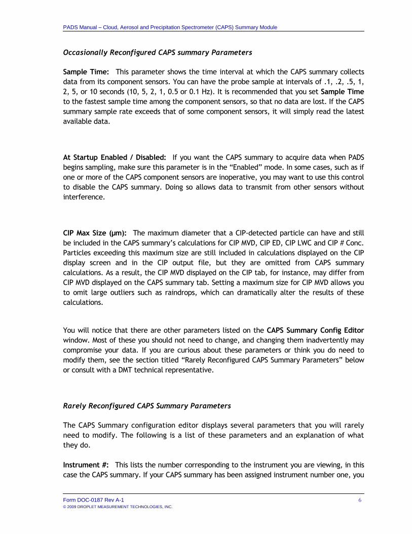
3. Now you can configure the instrument parameters to your desired specifications. You
will find a list of the parameters you may want to reconfigure in the two sections
below, “Occasionally Reconfigured CAPS summary Parameters” and “Rarely
Reconfigured CAPS summary Parameters.” If at any time you would like to revert to
the previously saved values for the CAPS summary parameters, press Cancel to exit
the window without saving changes.
4. When you are done configuring the CAPS summary parameters, press Save at the top
of the Config editor window. (If you would instead like to revert to the previously
saved values, click Cancel.) Then press the green Reset Program button for the new
configuration to take effect. Note that pressing the Reset Program button will clear
any data currently being displayed.
Figure 1: CAPS Configuration Editor Window
PADS Manual – Cloud, Aerosol and Precipitation Spectrometer (CAPS) Summary Module
Form DOC-0187 Rev A-1 6 © 2009 DROPLET MEASUREMENT TECHNOLOGIES, INC.
Occasionally Reconfigured CAPS summary Parameters
Sample Time: This parameter shows the time interval at which the CAPS summary collects
data from its component sensors. You can have the probe sample at intervals of .1, .2, .5, 1,
2, 5, or 10 seconds (10, 5, 2, 1, 0.5 or 0.1 Hz). It is recommended that you set Sample Time
to the fastest sample time among the component sensors, so that no data are lost. If the CAPS
summary sample rate exceeds that of some component sensors, it will simply read the latest
available data.
At Startup Enabled / Disabled: If you want the CAPS summary to acquire data when PADS
begins sampling, make sure this parameter is in the “Enabled” mode. In some cases, such as if
one or more of the CAPS component sensors are inoperative, you may want to use this control
to disable the CAPS summary. Doing so allows data to transmit from other sensors without
interference.
CIP Max Size (µm): The maximum diameter that a CIP-detected particle can have and still
be included in the CAPS summary’s calculations for CIP MVD, CIP ED, CIP LWC and CIP # Conc.
Particles exceeding this maximum size are still included in calculations displayed on the CIP
display screen and in the CIP output file, but they are omitted from CAPS summary
calculations. As a result, the CIP MVD displayed on the CIP tab, for instance, may differ from
CIP MVD displayed on the CAPS summary tab. Setting a maximum size for CIP MVD allows you
to omit large outliers such as raindrops, which can dramatically alter the results of these
calculations.
You will notice that there are other parameters listed on the CAPS Summary Config Editor
window. Most of these you should not need to change, and changing them inadvertently may
compromise your data. If you are curious about these parameters or think you do need to
modify them, see the section titled “Rarely Reconfigured CAPS Summary Parameters” below
or consult with a DMT technical representative.
Rarely Reconfigured CAPS Summary Parameters
The CAPS Summary configuration editor displays several parameters that you will rarely
need to modify. The following is a list of these parameters and an explanation of what
they do.
Instrument #: This lists the number corresponding to the instrument you are viewing, in this
case the CAPS summary. If your CAPS summary has been assigned instrument number one, you

PADS Manual – Cloud, Aerosol and Precipitation Spectrometer (CAPS) Summary Module
Form DOC-0187 Rev A-1 7 © 2009 DROPLET MEASUREMENT TECHNOLOGIES, INC.
will see “1” in this field. You should not need to modify the instrument number, and in fact
you are unable to do so from within PADS.
CIP Instr #: The instrument number that has been assigned to the CIP. This number
should match the Instrument # on the Config Editor screen for the CIP.
CAS Instr #: The instrument number that has been assigned to the CAS. This number
should match the Instrument # on the Config Editor screen for the CAS.
Hotwire Instr #: The instrument number that has been assigned to the Hotwire LWC.
This number should match the Instrument # on the Config Editor screen for the
Hotwire_LWC.
After making changes in the instrument configuration window, you will need to press the Save
button and then click the green Reset Program to activate these changes. Clicking Reset
Program will clear any data PADS is currently displaying.
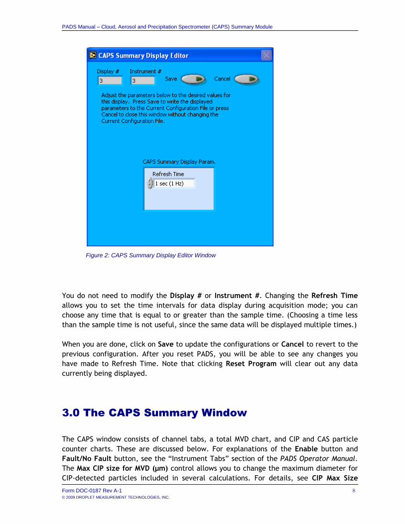
Configuring the CAPS Summary Display
To configure the CAPS Summary display, go to the Configure menu from the CAPS
Summary tab and select Configure Display. This will bring up the following window.
To configure the CAPS Summary display, follow the steps below.
1. Click on the “CAPS Summary” tab.
2. From the Configure menu, select Configure Display. You will see the following
window.
PADS Manual – Cloud, Aerosol and Precipitation Spectrometer (CAPS) Summary Module
Form DOC-0187 Rev A-1 8 © 2009 DROPLET MEASUREMENT TECHNOLOGIES, INC.
You do not need to modify the Display # or Instrument #. Changing the Refresh Time
allows you to set the time intervals for data display during acquisition mode; you can
choose any time that is equal to or greater than the sample time. (Choosing a time less
than the sample time is not useful, since the same data will be displayed multiple times.)
When you are done, click on Save to update the configurations or Cancel to revert to the
previous configuration. After you reset PADS, you will be able to see any changes you
have made to Refresh Time. Note that clicking Reset Program will clear out any data
currently being displayed.
3.0 The CAPS Summary Window
The CAPS window consists of channel tabs, a total MVD chart, and CIP and CAS particle
counter charts. These are discussed below. For explanations of the Enable button and
Fault/No Fault button, see the “Instrument Tabs” section of the PADS Operator Manual.
The Max CIP size for MVD (µm) control allows you to change the maximum diameter for
CIP-detected particles included in several calculations. For details, see CIP Max Size
Figure 2: CAPS Summary Display Editor Window

PADS Manual – Cloud, Aerosol and Precipitation Spectrometer (CAPS) Summary Module
Form DOC-0187 Rev A-1 9 © 2009 DROPLET MEASUREMENT TECHNOLOGIES, INC.
under the section “Occasionally Reconfigured CAPS Parameters.” The default for this
field is the value stipulated in the CAPS Summary Config Editor screen. You can change
this value by pressing on the arrows or by typing a new value directly into the field.
Channel Tabs
In the top left of the CAPS screen are the channel tabs. The first tab, CAPS Main
Parameters, displays key channels collected from the three CAPS Summary sensors—CIP,
CAS and Hotwire LWC. This tab is shown in Figure 3. The second tab, CAPS Diagnostics,
displays channels that indicate whether the sensors are functioning properly.
For information on specific channels, their definitions, and their acceptable ranges,
consult PADS Operator Manual’s Appendix A: Definitions.
Total MVD Chart Display
To the right of the tabular channel data is a chart of the total MVD for the combined size
distributions of the CIP and CAS. Currently the CAPS Summary does not calculate total
MVD, so the graph does not display any data. In the future, however, the program will
calculate and display this channel. Note: If you are reading a data file generated by an
older version of the PADS CAPS Summary module, you may also see values for Total MVD.
Figure 3: CAPS Main Parameters Tab

PADS Manual – Cloud, Aerosol and Precipitation Spectrometer (CAPS) Summary Module
Form DOC-0187 Rev A-1 1 0 © 2009 DROPLET MEASUREMENT TECHNOLOGIES, INC.
CAS and CIP Particle Counters
In the bottom half of the CAPS Summary window are the CAS and CIP particle counters.
These display a particle-size histogram for each instrument based on the current moment
in time.
On both charts, you can change the scale by typing a different number into the starting
and ending values on each axis. For instance, if you wanted to change Figure 4’s
maximum displayed particle count to 10, you would simply select the field that currently
says 100 and type in 10. In acquisition mode, you should disable autoscaling (see below)
before you modify fields in this way.
The charts also show you options for scaling and copying the data when you right-click on
them. These options are as follows:
Autoscale This autoscales the relevant axis. In autoscaling mode, the minimum
and maximum values of the axis are set automatically so that all data points can
be seen in the display. Note that on charts that have autoscale buttons, like the
large histogram chart on some instrument tabs, the buttons override the Autoscale
options in the drop-down menu. To see autoscaling options in the drop-down
menu, position the cursor over the relevant axis before right-clicking. Note that
you may not always be able to autoscale the x-axis.
Figure 4: CIP Particle Counter

PADS Manual – Cloud, Aerosol and Precipitation Spectrometer (CAPS) Summary Module
Form DOC-0187 Rev A-1 1 1 © 2009 DROPLET MEASUREMENT TECHNOLOGIES, INC.
Copy Data This copies the chart to the clipboard using a screen capture. This
chart can then be pasted into other documents like Word or PowerPoint
presentations.
Export Simplified Image This copies a simplified image of the data to the
clipboard or an output file. You can choose the format you desire—bitmap (.bmp),
encapsulated postscript (.eps), or enhanced metafile (.emf). Note that when you
select the .eps option, you must copy the data to a file. Unless you specify
otherwise, output files will be saved in the time-and-date-specific output file
directory for the current session.
Clear Graph This erases the currently displayed data points from the graph.

PADS Manual – Cloud, Aerosol and Precipitation Spectrometer (CAPS) Summary Module
Form DOC-0187 Rev A-1 1 2 © 2009 DROPLET MEASUREMENT TECHNOLOGIES, INC.
Appendix A: CAPS Summary Channels
A complete list of CAPS Summary data channels appears below. The CAPS output file will
contain data values for each channel for each sampling instance.
For definitions of the channels, see Appendix A in the PADS Operator Manual.
Time CAS Bin 2 CIP Bin 3 CIP Bin 34
CAS MVD (um) CAS Bin 3 CIP Bin 4 CIP Bin 35
CAS ED (um) CAS Bin 4 CIP Bin 5 CIP Bin 36
CIP MVD(um) CAS Bin 5 CIP Bin 6 CIP Bin 37
CIP ED (um) CAS Bin 6 CIP Bin 7 CIP Bin 38
(reserved for Total MVD) CAS Bin 7 CIP Bin 8 CIP Bin 39
(reserved for Total ED) CAS Bin 8 CIP Bin 9 CIP Bin 40
LWC Hotwire (g/m^3) CAS Bin 9 CIP Bin 10 CIP Bin 41
CAS LWC (g/m^3) CAS Bin 10 CIP Bin 11 CIP Bin 42
CIP LWC (g/m^3) CAS Bin 11 CIP Bin 12 CIP Bin 43
Airspeed CAS Bin 12 CIP Bin 13 CIP Bin 44
CAS Total Count CAS Bin 13 CIP Bin 14 CIP Bin 45
CAS Conc (#/cm^3) CAS Bin 14 CIP Bin 15 CIP Bin 46
CAS Laser Curr (mA) CAS Bin 15 CIP Bin 16 CIP Bin 47
CAS For TEC Temp (C) CAS Bin 16 CIP Bin 17 CIP Bin 48
CAS Internal Temp (C) CAS Bin 17 CIP Bin 18 CIP Bin 49
CIP Total Particles CAS Bin 18 CIP Bin 19 CIP Bin 50
CIP Conc (#/cm^3) CAS Bin 19 CIP Bin 20 CIP Bin 51
CIP Max Size for MVD CAS Bin 20 CIP Bin 21 CIP Bin 52
CIP End Diode Rej CAS Bin 21 CIP Bin 22 CIP Bin 53
CIP Over Range CAS Bin 22 CIP Bin 23 CIP Bin 54
CIP Ambient Temp (C) CAS Bin 23 CIP Bin 24 CIP Bin 55
CIP Diode Voltage 1 CAS Bin 24 CIP Bin 25 CIP Bin 56
CIP Diode Voltage 32 CAS Bin 25 CIP Bin 26 CIP Bin 57
CIP Diode Voltage 64 CAS Bin 26 CIP Bin 27 CIP Bin 58
CIP Laser Curr (mA) CAS Bin 27 CIP Bin 28 CIP Bin 59
Hotwire LWC (V) CAS Bin 28 CIP Bin 29 CIP Bin 60
LWC Slave (V) CAS Bin 29 CIP Bin 30 CIP Bin 61
Static Pressure (mb) CAS Bin 30 CIP Bin 31 CIP Bin 62
Pitot Pressure (mb) CIP Bin 1 CIP Bin 32 Status
CAS Bin 1 CIP Bin 2 CIP Bin 33 GPS Time

PADS Manual – Cloud, Aerosol and Precipitation Spectrometer (CAPS) Summary Module
Form DOC-0187 Rev A-1 1 3 © 2009 DROPLET MEASUREMENT TECHNOLOGIES, INC.
CAPS Summary channels fall into several broad categories:
Time Channels: Time and GPS Time store time data. Time is generated by the PADS
computer clock and is the time when the program receives the CIP data. GPS Time is
included in every instrument’s list of channels whenever a GPS is included as one of the
PADS instruments.
Bin Channels: Channels labeled CAS Bin [i] and CIP Bin [i] store data on the number of
particles of different sizes that the two probes have detected. These data are used in the
particle-count histograms in the bottom half of the CAPS tab.
Channels for Other Statistical Data: CIP End Diode Reject, CIP Over Range, CIP Total
Particles and CAS Total Count store particle statistics collected by the probes. Status
stores statistical data the CAPS has gathered on the communication between itself and
PADS.
Housekeeping Channels: Housekeeping channels are denoted by italics in the channels list
above. CIP housekeeping channels are generated by a 12-bit A/D converter that converts
a 0-10 V range to integer values from 0 to 4095. On the CAS, the input voltage range is 0-
5 V.
Calculated Channels: Channels labeled ED, MVD, LWC, and Conc store the results of
calculations PADS has performed on particle data. In future versions of PADS, the
channels currently labeled “(reserved for Total MVD)” and “(reserved for total ED)” will
be used to store MVD and ED calculations for combined CIP and CAS particle data.
Parameter Channel: CIP Max Size for MVD stores the setting for this instrument
configuration parameter at the time of the sampling instance.
Global Channel: Airspeed holds the true air speed generated by the master source
designated on the PADS Setup screen.