clogging mechanism of permeable concrete… · permeable concrete is a mixture of water, ......
TRANSCRIPT

Paper presented at Concrete 2013: Understanding Concrete conference, Gold Coast Australia, 16-18 Oct 2013
(Accepted Version). This version available at http://eprints.usq.edu.au/24554.
CLOGGING MECHANISM OF PERMEABLE CONCRETE: A REVIEW
Krishna Mishra
1, Yan Zhuge
2 and Warna Karunasena
3
1Student of Civil Engineering and Surveying,
2Associate Professor of Civil Engineering,
3Associate
Professor of Structural Engineering Center of Excellence in Engineered Fibre Composites (CEEFC)
School of Civil Engineering and Surveying University of Southern Queensland, Toowoomba, Australia
Abstract: Urbanization results in the conversion of pervious spaces to areas of impervious (paved)
surface which creates numerous problems such as erosion, flash floods, pollution of rivers and hot island in city. A sustainable solution to this problem is to use permeable pavements which only began to find application in Australia recently. Permeable pavements can facilitate biodegradation of oils from cars and trucks, help rainwater infiltrate into soil, replenish groundwater, allow tree roots to breathe, and reduce flash flooding, but they have not been widely adopted in Australia due to concerns mainly over reduced structural capabilities and clogging. A research project is being carried out at USQ aiming at understanding the influence of pore structures features and particle deposition on clogging resistance and permeability reduction. Clogging is perceived as a major problem for any type of permeable pavement. Even with vigorous maintenance clogging is common. In the paper, some common types of clogging are discussed first, followed by the clogging effect on the performance of porous concrete mainly related to the change of the porosity and the pore structure properties. Testing methods for measuring porosity and hydraulic conductivity which include both physical testing and image analysis are reviewed in detail.
Keywords: permeable concrete, clogging, pore structures, sedimentation
1 Introduction
Permeable concrete is a mixture of water, Portland cement, uniformly graded coarse aggregates, and little or no fine aggregates with some additives (Fig 1). The porous structure allows both water and air to percolate through the matrix into the subsoil beneath. Because of the interconnected pores, pervious concrete provides infiltration and evaporation, produces volumetric storage, while providing the environmentally beneficial leaching of Ca and alkanity, and reducing thermal pollution and leaching of organic acids and compounds such as phenols, polynuclear aromatic hydrocarbon and endocrine disrupting compounds.
Figure 1. Sample of permeable concrete (1)
Permeable concrete pavements are used for reducing runoff and pollution temperature, and also for providing load bearing capacity. Moreover, these pavements help increase and purify ground water storage. However, this operating system has some limitations which restrict its use. Main concern about permeable concrete pavements is that it is prone to clogging. It has been shown that rapid decrease in infiltration rate of pervious pavement could occur during the first two years of service due to the clogging effect. Abbott and Mateos (2) performed in-situ infiltration rate test and showed that
approximately 10% of the initial level exists after 2-3 years of construction or 87% reduction of permeability happens after 3 years of construction. The clogging developed very rapidly in first few years, which caused a significant reduction of infiltration rate, for example, 30% to 50% reduction in country area; 40% to 70% reduction in cities and 60% to 90% reduction in the much polluted areas. There are three different types of clogging, however, only physical and chemical clogging will be reviewed in this paper.
2. Clogging Clogging refers to decrease in permeability due to physical, biological and chemical processes. In the literature survey conducted for this review, it is seen that 70% of clogging was caused by suspended solids (SS) and bubbles, 10% by chemical reactions, 15% by microbial growth, and 5% by other reasons (3), (4) and (5).
2.1 Types of Clogging Productivity of porous concrete pavement decreases due to several physical, chemical and biological processes. Physical clogging occurs when large particles deposit on the surface and sometimes deposit in inner zone. It also occurs due to accumulation of suspended solids and also due to the existence of small pores in the pavement. Chemical clogging refers to the formation of scales seriously affecting the performance of porous concrete pavements. Carbonates and sulphides of precipitated minerals lead to partial or complete blocking of pore spaces. Biological clogging is caused by the algae and bacteria and also by the penetration of plant roots which got attached with the particles, which leads to reduce the hydraulic conductivity in porous media (6), (7) and (8).
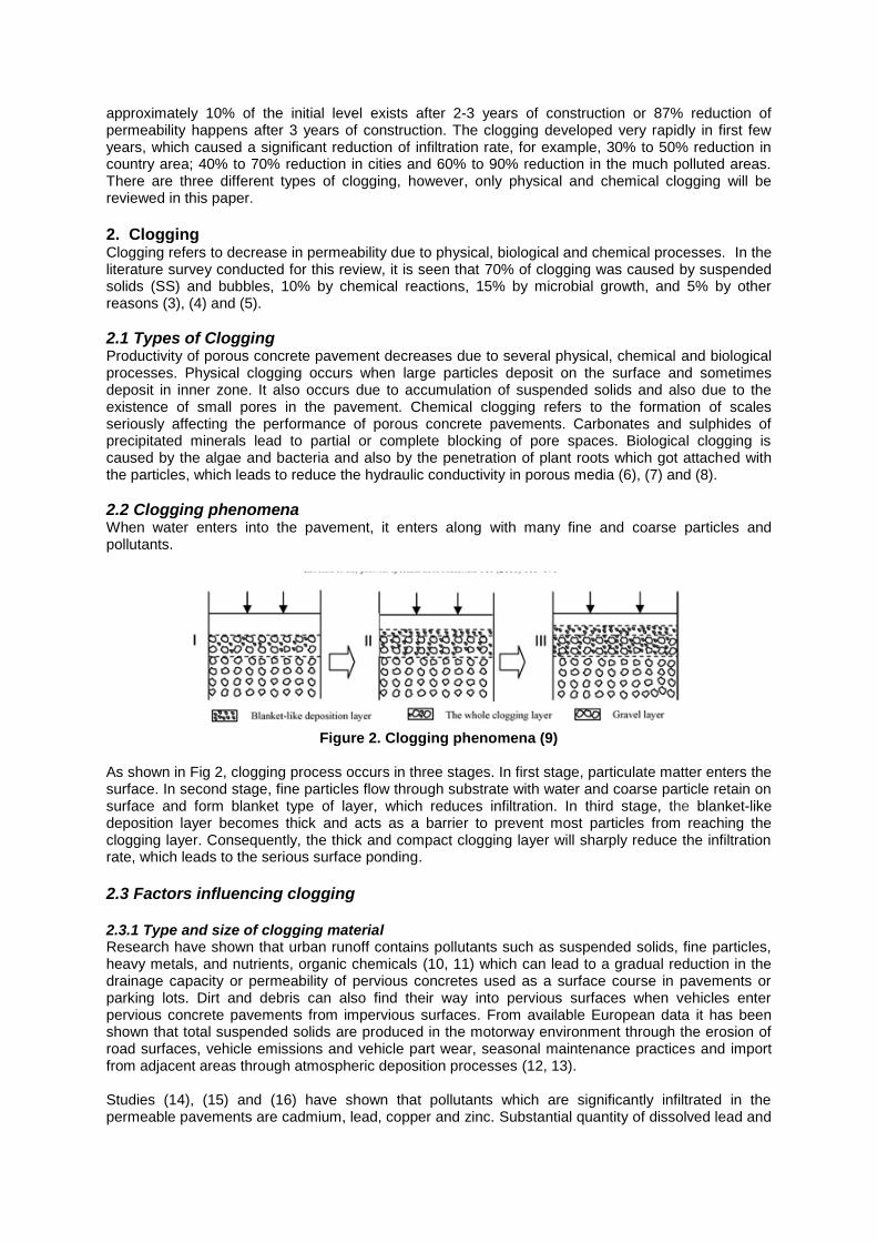
2.2 Clogging phenomena When water enters into the pavement, it enters along with many fine and coarse particles and pollutants.
Figure 2. Clogging phenomena (9)
As shown in Fig 2, clogging process occurs in three stages. In first stage, particulate matter enters the surface. In second stage, fine particles flow through substrate with water and coarse particle retain on surface and form blanket type of layer, which reduces infiltration. In third stage, the blanket-like deposition layer becomes thick and acts as a barrier to prevent most particles from reaching the clogging layer. Consequently, the thick and compact clogging layer will sharply reduce the infiltration rate, which leads to the serious surface ponding.
2.3 Factors influencing clogging 2.3.1 Type and size of clogging material Research have shown that urban runoff contains pollutants such as suspended solids, fine particles, heavy metals, and nutrients, organic chemicals (10, 11) which can lead to a gradual reduction in the drainage capacity or permeability of pervious concretes used as a surface course in pavements or parking lots. Dirt and debris can also find their way into pervious surfaces when vehicles enter pervious concrete pavements from impervious surfaces. From available European data it has been shown that total suspended solids are produced in the motorway environment through the erosion of road surfaces, vehicle emissions and vehicle part wear, seasonal maintenance practices and import from adjacent areas through atmospheric deposition processes (12, 13). Studies (14), (15) and (16) have shown that pollutants which are significantly infiltrated in the permeable pavements are cadmium, lead, copper and zinc. Substantial quantity of dissolved lead and

lesser quantity of zinc are adsorbed on the clogging particles. Copper and cadmium are not significantly affected by contact with the clogging material (17). Analysis of the materials which are trapped in pores has been done. It is found (Fig 3) that materials found are fine particles, organic materials and metals (copper, lead and zinc) sobbed on particles (18, 19).
Figure 3. Heavy metal distribution (19) Figure 4. Size ranges of particles (20) The diameter of clogging particle ranges from 10
-7 to 10
-4 m. As shown in Figure 4, particles of size
between 0.01 to 10 μm are classified as colloids. Particles at the top range, from 1 to 100 μm, are referred to as suspended particles. The transition zone from colloid to non-colloids is from 1 to 10 μm. A term particle refers to solids suspended in water with size of 1 to 100 μm. After measuring the permeability from 5 different locations having site characteristics like traffic flow, erosion, vegetation cover, sediments accumulation, maintenance practice, presence of cracking and rainfall, it was concluded that fine particles (less than 38µ) is an important factor for the reducing the permeability (20).
2.3.2 Flow rate Yong and Deletic (21) had performed two laboratory experiments on an accelerated time scale over 3 years. Details can be found in (21). In the first experiment, a constant continuous inflow regime without any drying sequence was simulated while varied inflow with drying sequences was simulated in the second experiment. Three widely used porous pavements were chosen for this study; (I) a standard bituminous asphalt surface, in which all the fines have been removed, a filter layer of crushed aggregate and a reservoir layer. (II) a 80 mm thick concrete paver with a unique chamber and bevel system, which is laid on a 50 mm course of 5 mm stone. The laying course is further separated from the upper and lower sub-base by a layer of geotextile. (III) Porous pavements made from crushed gravel of 50 mm thickness and placed over a layer of 5-20 mm screen crushed rock. It was concluded that degree of clogging which is hydraulic resistance increased with decreased in flow. Clogging behavior and life span of porous pavements varied by their design and position at which clogging layer was formed. Rate of clogging was also dependent on which pavements were exposed. System which received variable flow magnitude along with long drought condition were found to have doubled the life span of systems received low magnitude with the absence of drought. 2.3.3 Gradation Permeability depends upon gradation of aggregates. Pervious concrete is a mixture of cement, aggregates, water with some additives. Coarse aggregates are used instead of fine aggregates to get good porosity. If gradation of aggregates is not designed properly it can influence porosity as well as strength of pervious concrete. Very large size of aggregates can make concrete weaker in strength. On the other hand use of small aggregates can reduce its functional characteristic. Proper gradation is necessary for pervious concrete. Various studies (12), (22) and (23) used the gradations which were aimed at the porosity between 15 to 30%. The gradations included #8 (passing of aggregate from 4.75mm of sieve and retained on 2.36 mm sieve), #4(passing of aggregate through 9.5mm of sieve and retained on 4.75 mm of sieve) and 3/8”( passing of aggregate through 12.5mm of sieve and retained on 9.5 mm of sieve). Using single size of aggregates or blending them together with a percentage of 25, 50 and 75% by their weight can also get the porosity between 15 to 30%. Tan et.al (24) concluded from their theoretical model and experimental results that by keeping the gradation narrow and by limiting the number of aggregate sizes, the voids could be larger. This enabled more clogging materials to be entrapped within the specimens before low permeability was reached.
3. Experimental Studies on the clogging process

To understand the issues of clogging in the pervious concrete, laboratory studies and theoretical studies have been conducted. Various tests were performed in the laboratory to understand the clogging in pervious concrete samples.
3.1 Clogging test There are many experimental investigations conducted on the clogging of pervious concrete. Most of the experiments were conducted on the principle similar to falling head permeability testing and the reductions in permeability were measured. Youngmin (25) used 50gm of clogging materials to mix them into a 1kg bucket of water. They poured clogging liquid into the sample in the clogging apparatus as shown in Fig 5. The procedure was repeated until the sample was clogged and then was placed in the falling head permeability test to determine the reduction in permeability. Kayhanian (10) assessed the evidence of clogging through CT scan image. After clogging test they sliced the specimen and performed image analysis to determine the reduction in porosity. Image analysis will be discussed later in this paper.
Figure 5. Device used to clog pervious concrete (25) Figure 6. Falling Head testing setup (13)
3.2 Permeability test The most distinguished feature of pervious concrete is its high permeability. It is the property indicating the flow of water through the pore space which depends on materials, mixtures compaction and placing operation. Permeability is governed by the capillary pores in the cement paste. Pores that are too large will result in a high permeability, while pores that are small will result in a low permeability. Permeability is technically termed as Hydraulic conductivity (K) which is the measurement of clogging. The permeability is the most important parameter used in hydrological design of pervious concrete. Falling head testing setup is shown in Fig 6.
Most permeability measurements are based on the theory of Darcy’s Law and the assumption of laminar flow within the pervious concrete. Coefficient of permeability is expressed as
(1)
Where A1 and A2 are the areas of the cross-section of the sample and the tube, respectively, and l is the length of the specimen. For a given specimen geometry, h1 and h2 are initial and final heads, t is the time taken by water to drop from h1 to h2 and K is the coefficient of permeability. More details can be found in (23, 26 and 27). The assumption of laminar flow may not be always valid due to the large pore geometry. When pore size is about 0.6 cm, the flow conditions within specimen moves from laminar to transition flow. Darcy’s law may not be valid for these cases. Permeability calculated using Carman-Kozeny equation show fairly good agreement with the measured values. This will be discussed in detail in a later section. There is no universal mathematical relationship established between porosity and permeability of pervious concrete (28). Additionally, the non-destructive electrical method (30) and three-dimensional planar images method described by Sumanasooriya (29) can also be used to predict the permeability of pervious concrete.
3.3 Porosity test
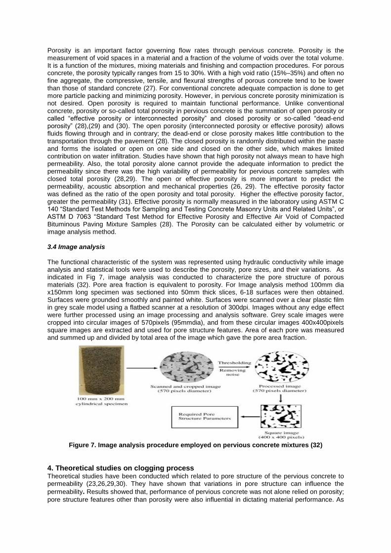
Porosity is an important factor governing flow rates through pervious concrete. Porosity is the measurement of void spaces in a material and a fraction of the volume of voids over the total volume. It is a function of the mixtures, mixing materials and finishing and compaction procedures. For porous concrete, the porosity typically ranges from 15 to 30%. With a high void ratio (15%–35%) and often no fine aggregate, the compressive, tensile, and flexural strengths of porous concrete tend to be lower than those of standard concrete (27). For conventional concrete adequate compaction is done to get more particle packing and minimizing porosity. However, in pervious concrete porosity minimization is not desired. Open porosity is required to maintain functional performance. Unlike conventional concrete, porosity or so-called total porosity in pervious concrete is the summation of open porosity or called “effective porosity or interconnected porosity” and closed porosity or so-called “dead-end porosity” (28),(29) and (30). The open porosity (interconnected porosity or effective porosity) allows fluids flowing through and in contrary; the dead-end or close porosity makes little contribution to the transportation through the pavement (28). The closed porosity is randomly distributed within the paste and forms the isolated or open on one side and closed on the other side, which makes limited contribution on water infiltration. Studies have shown that high porosity not always mean to have high permeability. Also, the total porosity alone cannot provide the adequate information to predict the permeability since there was the high variability of permeability for pervious concrete samples with closed total porosity (28,29). The open or effective porosity is more important to predict the permeability, acoustic absorption and mechanical properties (26, 29). The effective porosity factor was defined as the ratio of the open porosity and total porosity. Higher the effective porosity factor, greater the permeability (31). Effective porosity is normally measured in the laboratory using ASTM C 140 “Standard Test Methods for Sampling and Testing Concrete Masonry Units and Related Units”, or ASTM D 7063 “Standard Test Method for Effective Porosity and Effective Air Void of Compacted Bituminous Paving Mixture Samples (28). The Porosity can be calculated either by volumetric or image analysis method. 3.4 Image analysis The functional characteristic of the system was represented using hydraulic conductivity while image analysis and statistical tools were used to describe the porosity, pore sizes, and their variations. As indicated in Fig 7, image analysis was conducted to characterize the pore structure of porous materials (32). Pore area fraction is equivalent to porosity. For Image analysis method 100mm dia x150mm long specimen was sectioned into 50mm thick slices, 6-18 surfaces were then obtained. Surfaces were grounded smoothly and painted white. Surfaces were scanned over a clear plastic film in grey scale model using a flatbed scanner at a resolution of 300dpi. Images without any edge effect were further processed using an image processing and analysis software. Grey scale images were cropped into circular images of 570pixels (95mmdia), and from these circular images 400x400pixels square images are extracted and used for pore structure features. Area of each pore was measured and summed up and divided by total area of the image which gave the pore area fraction.
Figure 7. Image analysis procedure employed on pervious concrete mixtures (32)
4. Theoretical studies on clogging process Theoretical studies have been conducted which related to pore structure of the pervious concrete to permeability (23,26,29,30). They have shown that variations in pore structure can influence the
permeability. Results showed that, performance of pervious concrete was not alone relied on porosity;
pore structure features other than porosity were also influential in dictating material performance. As

permeability is found to increase with increasing aggregate sizes and the associated pore sizes, the size of the pores can be considered as an important pore structure feature. In addition, the transport of water through the material requires that the pore system be connected. Therefore, connectivity is another significant factor affecting the clogging process of porous concrete.
4.1 Pore connectivity The connectivity of the pore structure is very crucial for the permeability of porous materials. Impedance spectroscopy is a powerful tool to measure the transport properties of cement based materials, because it can provide much information about the microstructure. This information can be used as input to microstructure models. Solartron 1260 Impedance / gain phase analyzer was used for the Electrical Impedance Spectroscopy (EIS) measurements in order to determine the pore connectivity (30). Experimental set up of EIS is shown in Fig 8. Nyquist plot was obtained through which bulk resistance Rb was measured. Sodium chloride was used as electrolyte of known conductivity to fill the pores. The Rb facilitated calculation of the effective sample conductivity. Pore connectivity was calculated by measuring the porosity, conductivity of electrolyte and effective electric conductivity (Eq 2).
. (2)
where β is the pore connectivity factor, σeff is the effective electric conductivity, σo is the conductivity of electrolyte and ɸv is the measured porosity.
Figure 8. Electrical impedancemeasurement set up (30)
The pore connectivity factor (β) determined from electrical measurements increased with increasing porosity and pore sizes. Smaller aggregate sizes (and thus pore sizes) resulted in reduced connectivities because of the presence of a larger number of apertures or throats in specimens, which contributed to the reduction of conductivity (33, 34 and 35). Some of the studies had also mentioned that increasing in porosity did not mean an increase in pore connectivity. When certain aggregate blends were used, the smaller particles might not be able to fill in the spaces between the larger particles resulting in higher porosity, but the arrangements of the particles might result in lower pore connectivity (26).
4.2 Tortuosity As water flows through permeable concrete, it flows through interconnected path which is tortuous in nature. It is assumed that all effects arising from pore orientation, connectivity and size variation can be lumped together as a single tortuosity factor (28).
Figure 9. The Indication of Tortuosity of Pervious Concrete (28) As indicated in Fig 9, it is the length of the flow path covered by species divided by the straight path. Therefore, tortuosity is the ratio of the length covered by species to the straight path L of the sample

which is a pure geometrical factor independent of solid and fluid densities. A relationship between tortuosity and porosity has been found in Eqn. 3 (28):
(3)
where α is the tortuosity and r = ½ for spheres and lies between 0 to 1 for other ellipsoids, and is the porosity. As predicted from Eqn. (3), with the increase of porosity, the tortuosity decreases. A general relationship between porosity and tortuosity might be obtained. The minimum tortuosity is calculated equal to 0.5 (28, 36). Permeability increases with increases in pore size, pore connectivity and porosity. However, as indicated in Fig 10, permeability decreases with increases in tortuosity. 4.3 Permeability prediction using pore structure features The relationship between permeability, porosity and pore structure features has been developed based on Kozeny–Carman equation which combines Darcy’s law and pore geometrics as shown in Eq. 4.
{ ⁄ }
. (4)
where pore tortuosity ⁄ , specific surface area of CPP (SSA), and total porosity of CPP (ɸt) , shape factor C0 that accounts for the shape of the pores, ranges from 2 to 3 depending on the assumption of either circular or rectangular pores and for a filter media pore distribution is assumed to be 2.5.
Figure 10. Variation of permeability with tortuosity (36)
According to Neithalath (32), intrinsic permeability depends on porosity, pore size distribution, pore roughness, constrictions of the pore space, the tortuosity and connectivity of the internal pore
channels. Hydraulic conductivity can be related to intrinsic permeability as K=k
where ρ = density of
fluid, g = acceleration due to gravity and µ = dynamic viscosity. Intrinsic permeability can be described by simplifying Eq 5.
(5)
where Fs is the generalized factor for different pore shapes. Furthermore, Tan (24) used Konzeny-Carman equation to derivate decreased permeability as a result of clogging which can be represented as a function of initial permeability, porosity and specific deposit of clogging material:
k=
[ ] (6)
where k is the permeability of specimen, k0 is the average initial permeability of specimen, n is the porosity of the specimen, σ is the specific deposit and it is the ratio of bulk volume of base specimen and volume of clogging material; α is the empirical constant. In Eq 6, when clogging materials are able to completely fill up the void spaces, α will be taken as 1. Theoretically it means that permeability is zero. The value of α indicates the rate of deterioration in permeability. Higher value of α implies more rapid decrease in permeability. Another study on the permeability reduction is based on the idealized geometric model of pervious concrete and on the probability of particle capture to evaluate permeability reduction. Reduction in pore size because of particle retention as a function of the number of n runs (series of particle and water addition) could be related to the reduction in flow through the pore channels. Mathematically, it is stated as in Eq 7.
(7)
where N(ri,aj) is the number of particles of radius aj deposited in a pore radius ri. Q(ri) = flow rate through a pore radius ri, and p(ri,aj) is the probability of deposition of particles of radius aj in a pore radius ri and C(aj) is the number of particles of size aj per unit column of water in the pore structure.
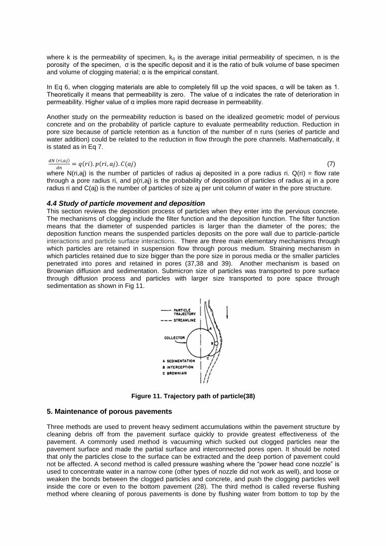
4.4 Study of particle movement and deposition This section reviews the deposition process of particles when they enter into the pervious concrete. The mechanisms of clogging include the filter function and the deposition function. The filter function means that the diameter of suspended particles is larger than the diameter of the pores; the deposition function means the suspended particles deposits on the pore wall due to particle-particle interactions and particle surface interactions. There are three main elementary mechanisms through which particles are retained in suspension flow through porous medium. Straining mechanism in which particles retained due to size bigger than the pore size in porous media or the smaller particles penetrated into pores and retained in pores (37,38 and 39). Another mechanism is based on Brownian diffusion and sedimentation. Submicron size of particles was transported to pore surface through diffusion process and particles with larger size transported to pore space through sedimentation as shown in Fig 11.
Figure 11. Trajectory path of particle(38)
5. Maintenance of porous pavements Three methods are used to prevent heavy sediment accumulations within the pavement structure by cleaning debris off from the pavement surface quickly to provide greatest effectiveness of the pavement. A commonly used method is vacuuming which sucked out clogged particles near the pavement surface and made the partial surface and interconnected pores open. It should be noted that only the particles close to the surface can be extracted and the deep portion of pavement could not be affected. A second method is called pressure washing where the “power head cone nozzle” is used to concentrate water in a narrow cone (other types of nozzle did not work as well), and loose or weaken the bonds between the clogged particles and concrete, and push the clogging particles well inside the core or even to the bottom pavement (28). The third method is called reverse flushing method where cleaning of porous pavements is done by flushing water from bottom to top by the

water stored beneath the pavement using very low pressure (40). Studies have shown that if maintenance has not been applied on time or after a clogging phenomenon or after the reduction in permeability rate to 0.1cm/s there would be no improvement in the infiltration rate with sweeping followed by vacuuming because of the fully clogging.
6. Conclusion The following conclusions can be drawn from this review:
1. Clogging occurs due to the entrapment of particles. It depends on size, type of particles as well as flow rate and gradation. It is also known that clogging can be determined by various experimental methods such as permeability and clogging test.
2. Maximum reduction in permeability (60 to 90%) occurred in the urban areas due to pollution. 3. Pore structure influences clogging. Permeability depends on pores size, pore connectivity and
tortuosity. Permeability increases with the increase of pore size and pore connectivity. The chances of clogging decreases with increases in permeability.
4. Clogging particles settled through various mechanisms. Submicron size particles are transported through diffusion process whereas larger particles are transported through sedimentation.
5. Large particles which are retained can be removed by vacuuming or back flushing techniques. However, the submicron particles which were deposited through diffusion process are hard to remove. The objective of the current research is to understand diffusion process through experiments as well as to develop mathematical model to determine the diffusion coefficient.
7. References
1. Yukari, A. , “Development of Pervious Concrete”, University of Technology, Sydney,2009 2. Abbott,C. & Mateos, C., ”In-situ hydraulic performance of a permeable pavement sustainable
urban”, Journal of the Chartered Institution of Water and Environmental Management,2003, vol. 17, no. 3, pp. 187-90.
3. Dillon, P. , ”Review of International Experience in Injecting Water”,November 1994 pp. 21-5. 4. Henry, M., JP et al., , “Towards a description of particulate fouling: from single particle
deposition to clogging”, Adv Colloid Interface Sci, 2012, vol. 185-186, pp. 34-76, item: 23141134
5. Santo,R., Thierry. et al., ”interrelationships betn biological, chemical and physical processes as an analog to clogging in aquifer storage abd recovery (ASR) wells”, Water Res, 2000 vol. 34, no. 7, pp. 2110-8.
6. Murat, B., “Soil clogging phemomena.”, , Water Sci tech, 1997, vol. 35, no. 5, pp. 183-8. 7. Nathalie, R., Richard,V. et al., “Clogging of a limestone fracture by stimulating groundwater
microbes”', Water.Res.,2001 vol. 35, no. 8, pp. 2029-37. 8. Yang, “Study on Clogging Mechanism and Control Methods of Artificial Recharge”,
Proceedings of the International Conference on Challenges in Environmental Science and Computer Engineering, 2010 pp. 29-32.
9. Hua, GF., Zhu, W. et al., “Clogging pattern in vertical-flow constructed wetlands: Insight from a laboratory study”, Journal of Hazardous Materials, 2010 vol. 180, no. 1-3, pp. 668-74
10. Kayhanian, M., Anderson, D. et al, “Permeability measurement and scan imaging to assess clogging of pervious concrete pavements in parking lots”, J Environ Manage, 2012 vol. 95, no. 1, pp. 114-23, item: 22115516
11. Pratt, CJ., Mantle, J. et al., “UK reserach in to the performance of permeable pavement, reservoir structutes in controllong stormwater discharge quantity and quality”, Water Sci. Techno,1995 vol. 32, no. 1, pp. 63-9.
12. Deo, O., Samanssoriya,M.et al., ”Permeability Reduction in Pervious Concretes due to Clogging: Experiments and Modeling”,2010
13. Lundy, Ellis et al., ”Risk prioritisation of stormwater pollutant sources”, Water Res,2012 vol. 46, no. 20, pp. 6589-600, item: 22078253.
14. Kayhanian, M., Fruchtman, BD. et al., “Review of highway runoff characteristics: comparative analysis and universal implications”, Water Res, 2012 vol. 46, no. 20, pp. 6609-24, item: 22959661
15. Kalmykova,Y., Bjorklund, K. et al., “Partitioning of polycyclic aromatic hydrocarbons, alkylphenols, bisphenol A and phthalates in landfill leachates and stormwater”, Water Res, 2013 vol. 47, no. 3, pp. 1317-28, item: 23295068.
16. Bjorklund, K., “Sources and Fluxes of Organic Contaminants in urban run off”,2011 Chalmers University of Technology.
17. Legret, M.,Nicollet, M. et al, “Simulation of heavy metal pollution from stromwater infiltration through a porous pavement with reservoir structute”, Water. Sci. Techno, 1999 ,vol. 39, no. 2, pp. 119-25.
18. Welker, AL., Gilbert, JK. et al., “Examination of the Material Found in the Pore Spaces of Two Permeable Pavements”, Journal of Irrigation and Drainage Engineering, april 2013
19. Legret, M., Colandini, V. , “Effectsofaporouspavementwithreservoir’', Wat. Sci.Tech, 1999, vol.39, no. 2, pp. 111-7.
20. Hendrick, A.,”Investigation of clogging processes in unconsolidated aquifers near water supply wells”, Delft University of Technology, 2007.
21. Yong, CF., Deletic, A., “Factors that Predict Clogging through Porous Pavements.”, 7th international conference on water sensitive urban design: proceedings of the7th international conference on water sensitive urban design, Melbourne Cricket ground,2012
22. Neithalath, N., Weiss, J. et al. “Characterizing Enhanced Porosity Concrete using electrical impedance to predict acoustic and hydraulic performance”, Cement and Concrete Research, 2006, vol. 36, no. 11, pp. 2074-8
23. Neithalath, N., Weiss, J. et al ,”Predicting the Permeability of Pervious Concrete (Enhanced Porosity Concrete)”, 2011
24. Tan, S., Fwa, TF. et al, , “Clogging evaluation of permeable bases”, Journal of Transportation Engineering,2003 vol. 129, no. 3, pp. 309-15
25. Youngmin, J., Grasley, ZC., ”Evaluation and Optimization of Durable Pervious Concrete for Use in Urban Areas, Texas Transportation Institute”, Texas A&M University System College Station, Texas 77843-3135, 2008.
26. Low,K., Harz, D. et al, “Statistical Characterization of the Pore Structure of Enhanced Porosity Concretes.pdf”, concrete technology forum ,2008
27. Schaefer, V.R., Wang, K., et al, “Mix Design Development for Pervious Concrete in Cold Weather Climates”, Iowa State University, Ames, IA, 2006
28. Tong, B., “Clogging_effects_of_portland_cement_pervious_concrete”, Iowa State University,2011
29. Sumanasooriya, MS., Bentz, DP. et al, “Predicting the Permeability of Pervious Concretes from Planar Images”
30. Neithalath, N., Weiss, J. et al, “Predicting the Permeability of Pervious Concrete (Enhanced Porosity Concrete) from Non-Destructive Electrical Measurements”,2008
31. Crouch, LK., Cates, MA. et al 2003, “Measuring the effective air void content of portland cement pervious pavements”, ASTM International,2003, vol. 25, no. 1
32. Neithalath, N., Sumanasooriya, MS. et al, 'Characterizing pore volume, sizes, and connectivity in pervious concretes for permeability prediction', Materials Characterization, 2010,vol. 61, no. 8, pp. 802-13
33. Sumanasooriya, MS. & Neithalath, N., 'Pore structure features of pervious concretes proportioned for desired porosities and their performance prediction', Cement and Concrete Composites, 2011, vol. 33, no. 8, pp. 778-87
34. Narayanan.N, Adam, M. et al, 'Modeling the Influence of Pore Structure on the Acoustic Absorption of Enhanced Porosity Concrete' 2006
35. Neithalath, N., “Development and characterization of acoustically efficient cementitious materials”, Purdue University,2004
36. Ahmad, S., Azad, AK. et al , “A study of permeability and tortuosity of concrete”, 30th Conference on OUR WORLD IN CONCRETE & STRUCTURES,2005
37. Fogler, “Multilayer Deposition of Stable Colloidal Particles during”, Langmuir,1998, vol. 14. 38. Lakshmi .R, ”Particle transport in Soils review of significant processes’', Journal of
Infrastructure system, June 1997 39. Legoff,P., “Flow of Suspensions through Porous Media”, Industrial and engineering chemistry,
May 1970 vol. 62, no. 5 40. Nilesh,A., Scott,S., “Cleaning Porous Pavements Using a Reverse Flush Process”, Journal of
Transportation Engineering, November 2009, vol. 135, pp.832-838