clive elliott comes out from under the canvas to describe ... · clive elliott comes out from under...
TRANSCRIPT
SHELTERS
Clive Elliott comes out from under the canvas to describe some examples of British portable shelters.
Throughout the history of human conflict participants have sought to protect themselves from the elements. Places of sheltersuch as caves and woodland may not always be nearby, so tentage in some form evolved as the protection of choice. Inevitablythose commanding the proceedings will usually enjoy more comprehensive protection than the combatants will. This is not justbecause of the luxuries of rank but the need to facilitate planning and command of the activities. Tentage is the general term todescribe canvas covered fabrications. A tent is canvas supported by poles but is not free standing and requires the use of guyropes. A shelter is used to describe a free standing canvas accommodation that is supported by a frame but is merely stabilisedby guy ropes. A shelter is also used to describe a canvas attached to a vehicle or say a tree that gives it supports. A penthouseusually means a canvas shelter attached to a vehicle. In this first article I will be describing just a few of the shelters that theBritish Army have used since World War 2.
At the most basic level a shelter can consist of a canvas stretched over or attached to anything nearby.
A remarkably bendy tree forming the basis of a shelter.
A simple jungle shelter.
A more luxurious jungle shelter for non-tactical use.
A shelter using locally obtained elephant grass.
Two canvas sheets buttoned together and two poles formed the basis of Tent, Shelter, Mk 3, JA1856. This was a wartimeshelter that could be extended in length by buttoning together further sheets.
Tent, Shelter, Mk 3, JA1856.
The floor space was 7ft x 5ft 3in with a ridge height of 3ft stability was assured by a bracing line supplied with each sheet.This rather draughty accommodation was replaced by Tent, Bivouac without netting JA 6920.
Protection is not just needed against the natural elements; consideration has to be given to NBC protection. Perhaps one of themost bizarre forms of shelter is the Kit, Individual, Protection. Large numbers of these kits have appeared on the surplusmarket recently and provide a very economical source for groundsheets, pegs and cordage.
Kit, Individual, Protection, F2/8465-99-120-6227
The kit comprises a sheet 2m x 1.5m of green tear-resistant plastic, six aluminium tubular pegs and 18m of nylon cord. Theidea is to dig a trench, secure the pegs to allow a zigzag of cordage, over this place the plastic sheet and then cover it with turf.The soldier then cautiously slides in underneath and is thus protected from the excesses of nuclear warfare.
Trench no more than 0.6m wide.
The pegs to be driven in below ground level and the sheet unfurled.
Soil is added to the perimeter.
Soil is built up to a height of 4.5cm.
Soil is added over the entire shelter to give a dome shape.
Two soldiers can be accommodated in single trench 0.61m - 0.92m wide by combining two protection kits.
Remploy Ltd manufactured the protection kits in the early 1980s. The instructions for assembly gave precise imperialmeasurements for assembly and neat diagrams. The instructions indicate how the outer and inner sealed bags should beremoved, although the instruction card itself is sealed within the inner bag!
In the 1990s the manufacturer changed to Papworth along with the instruction card. The card now quotes metric measurementsand new diagrams. Although the diagrams are larger, they are drawn crudely, printed badly and less easy to understand.

A significant addition though is the warning in red “INCORRECT ASSEMBLY MAY RESULT IN DANGEROUSCOLLAPSE”. Apart from the British Army the kits have been supplied to The Netherlands, Australia and New Zealand.
The facilities of a vehicle can be greatly enhanced by shelters attached to the sides. This can simply be for storage, equipmentservicing, communication equipment, command facilities or for crew accommodation. A vehicle that saw particular use as arepair vehicle was the Truck, 3-Ton, GS, 4x4, Commer Q4. The large house body on the Commer provided a work area thatcould be customised for a particular role. The general layout was to have workbenches and storage drawers down each side.The electrical supply was 415 volts 3-Phase AC provided by an external source via a trip switch. Although there was provisionfor a 240-volt 1-phase AC supply to be used instead. The 240 volts AC supplied the bench power points, heaters, generallighting and the extractor fans. A transformer and rectifier unit giving 39 volts DC powered an adjustable speed ventilation fan.A transformer providing 24 volts AC supplied the bench lamps. Although ventilation was standard, air conditioning could beprovided from an external trailer. If necessary the accommodation could be blacked out.
The principal variants were:Radar Repair.Telecommunication Repair.Armourers. Total of 5 vices. Racks provide storage for 44 rifles and 13 Bren guns.Recuperator Repair. For testing parts of an artillery recoil system.Fuel Injection Equipment Repair. Hartridge test bench, kerosene bath, pressure cleaning cabinet. 3 mechanics.Electrical Repair. For MT electrical systems, 2 vices, bench grinder, Crypton test bench, Octopus test bench.Instrument Repair. Divided into 2 compartments, the forward compartment providing a dust-free environment. 5 mechanics.
With the exception of the Recuperator Repair Truck, all Repair Commers had the option of a lean-to-shelter that could beerected on either side of the vehicle. The shelter frame consisted of four vertical posts, three sidemembers, four roof supportsand stabilised by six guy ropes. The tentage was made of a vinyl-covered material called ‘Vyanide’ with oiled cotton windows.Each side of the vehicle had a narrow Vyanide apron to deflect rainwater from the shelter. The vehicle itself was stabilised byfour screw jacks, one placed at each corner of the vehicle. The screw jacks and the shelter were carried in the metal locker onthe roof. Power for the shelter was obtained from a distribution panel at the rear of the vehicle.
Truck, 3-Ton, GS, Instrument repair, 4x4 with side shelter.
Truck, 3-Ton, GS, Instrument Repair, 4x4 with side shelter.

Side apron for shelter. Note Telecom Repair has only two side windows.
Recuperator Repair Truck had no shelter.
There was no ventilator fitted to the rear of the Recuperator Repair Truck as the rear panels had to be removed to access alifting gantry. The other variant that had no provision for a lean-to-shelter was the Command Truck, this may seem rathercurious but the reason was that there was a special shelter used just for the Command role. Shelter, Portable, No. 25 Mk 1could be erected at either side of the vehicle or at the rear. An annexe tent was provided at the rear of the vehicle that could bejoined to the shelter by means of a canopy. The annexe was supported on a U-shaped frame fixed in position above the reardoor of the vehicle. Twelve guys provide additional stabilty for the main shelter and the side curtains could be secured bytwenty five pegs or stabilised by filling sand pockets.
Shelter, Portable, No. 25 Mk . Note annexe on vehicle rear door.
The shelter was supported on a tubular frame supporting the panels of Vyanide. There were three oiled cotton windows on theright side and two windows on the left side. The windows could be blacked out with rolled blinds secured by press fasteners.
Length of main tent 13ft 3in (4.04 m)Width of main tent 6ft 11in (2.12 m)Height of main tent (at centre) 7ft 2½ in (2.2 m)Length of annexe 4ft 3½ in (1.31 m)Width of annexe 2ft 1½ in (0.65 m)Height of annexe 6ft 0in (1.83 m)

Large trucks and containers were often enhanced by the use of ‘lean to’ shelters and can be identified by a canvas or Vyanideapron.
Truck, 10-Ton, 6x4, GS, (Albion) Machinery RE (FV11102)
Truck, 3-Ton, MT Repair, Mk.2, 4x4, Bedford (FV13113)
Container, Transportable, Vehicle Mounted, 3-Ton (CB302)
CB302 with shelter.
The essential functions of trailers were often dependent on tentage.
Trailer, 2-Ton, Airportable, Photographic Film Printing (Hand) FV2504(C).
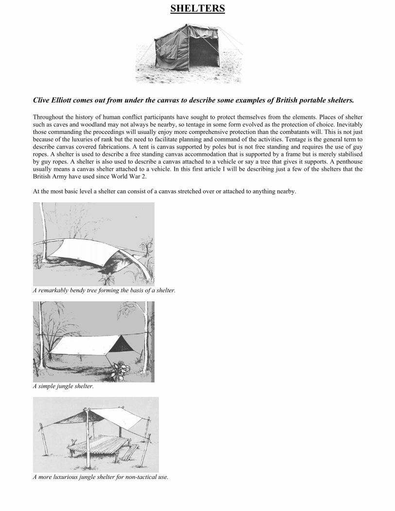
The most significant increase in accommodation is demonstrated by the extensions fitted to the ½ Ton Trailer FV2308. Thistrailer was intended to be towed behind a ¼ Ton Rover Mk 8 and could fulfil a variety of roles such as repair workshop, cypheroffice, radio relay, repeater, terminal station etc.
Radio Repair Installation in Trailer ½ Ton FV2308(U).
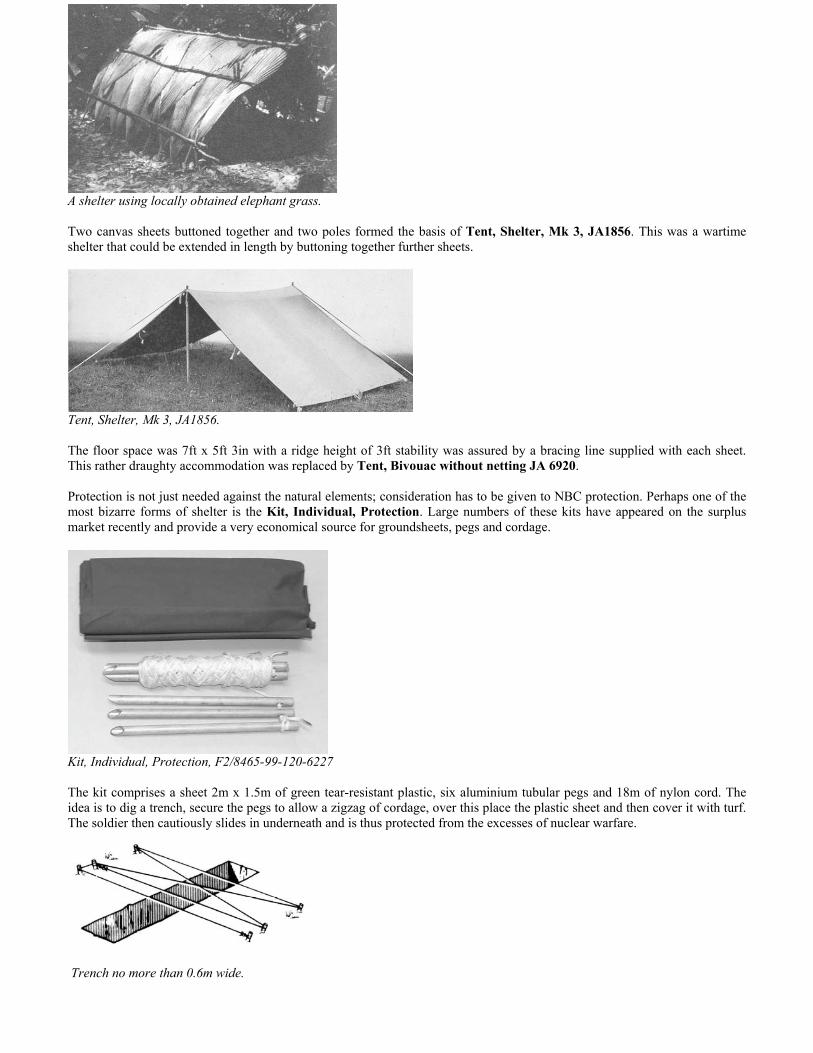
Tubular frame assembled.
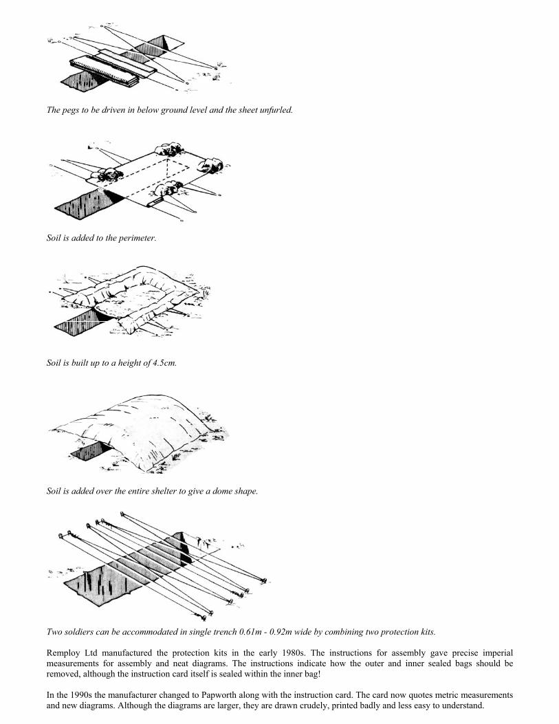
Trailer now engulfed with a shelter on both sides.
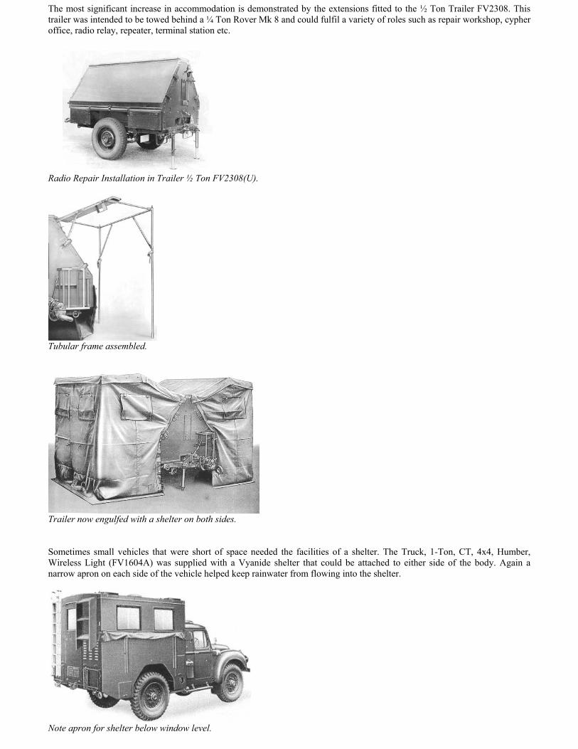
Sometimes small vehicles that were short of space needed the facilities of a shelter. The Truck, 1-Ton, CT, 4x4, Humber,Wireless Light (FV1604A) was supplied with a Vyanide shelter that could be attached to either side of the body. Again anarrow apron on each side of the vehicle helped keep rainwater from flowing into the shelter.
Note apron for shelter below window level.

The shelter provided more space than within the vehicle body.
Inside the shelter showing the folding tubular poles.
The entrance flaps at each end allowed the shelter to be fitted on either side of the vehicle.
A disadvantage of this shelter was that there was no direct access to the vehicle without going outside the shelter. This problemwas overcome in the Austin vehicle designated Truck, 1-Ton, GS, Wireless Light. Note that this is a different designation fromthe Humber, which was not a GS Truck but a CT (Combat) truck. CT vehicles were designed specifically for military use andnot merely adaptations of commercial models like the Austin K9.
Truck, 1-Ton, GS, Wireless Light, Mk 2, Signal Centre Light.

A comprehensive shelter for the Austin WL was carried in a locker above the cab. Although there was a canvas skirt on eachside of the body for attaching shelters, it was the left side that was intended to accommodate the full penthouse installation.The feature of the penthouse was that it provided a covered passageway from the vehicle to the shelter.
Note frame at top that folds down to support part of penthouse. A platform and ladder are carried at the rear.
The main penthouse is supported on a folding tubular metal frame that attaches to the vehicle. The frame at the rear of thevehicle is now unfolded beneath this the rear platform and metal ladder have been installed.
The roof has been added and side skirt to exclude the weather as well as providing a blackout.
The main tentage now fitted and a rear skirt added.

The luxury of direct communication between vehicle and penthouse. Although self-supporting, note the needed for a sturdy guyrope to hold canvas taut.
The accommodation within the vehicle itself was divided into two by means of a heavy canvas curtain. The front portionhoused the telephone switchboard and system control. The rear portion housed the Signal Centre supervisor and clerk; thepenthouse accommodated Fullerphones and their operators. The Fullerphone is a telegraph signalling system that uses very lowcurrent and is less susceptible to enemy interception. The range of a Fullerphone is greater than a telephone and has theadvantage that it can be superimposed on telephones circuits without interaction between the two systems.
A good example of a rear-attached shelter is illustrated in the Truck, 1-Ton, Charging, Signals. This was an Austin K9 adaptedto provide battery charging facilities for 12 volt 75 Ah and 6 volt 170 Ah lead acid batteries. Given that the charging process islikely to produce hydrogen, the shelter lends itself to providing good ventilation. The batteries being placed at nearly groundlevel saves the effort of lifting to vehicle height and also reduces the chance of acid spillage.
User trials with a non-military Government registered Austin K9 truck.
Shelter frame with telescopic legs and folding stays.

Canopy in position tucked under the vehicle canvas.
Rear view of the shelter showing batteries on charge.
The shelter was not entirely light-proof as the battery racks extended outside the shelter. Just as light can leak out, dust, windand rain can leak in. Not too crucial for battery charging, but for some applications it was of paramount importance to work ina controlled environment. One of the most comprehensive of vehicle shelters must surely have been the arrangement for theTruck, Malkara Repair (FV1624). Here two shelters are set up on each side of the Humber. There is an interconnectionbetween the two shelters and the vehicle body. The shelters were assembled around a frame and integral flooring ensured acontrolled environment. This was particularly important, as sand was likely to be a problem given that the deployment areaenvisaged was the Middle East.
Note integral floor & access between shelters.
A dust-free environment for repairing the Malkara missile system.

A flysheet assures protection from the elements over the repair facility.
The design of this shelter was based on experience gained by REME Airborne Workshops whilst repairing Jeeps in World WarII and in Palestine. Considerable thought went into the development of these shelters that were only intended for three vehicles.After successful trials the canvas was made available in a more suitable colour for the Middle East.
The FV1604 and FV1624 were not the only Humbers to be embellished with additional accommodation. Some FFW HumberPigs (FV1612) were fitted with a rear penthouse. For some years I had been puzzled by a series of turn buckles around the reardoors of my Mk 1 Pig. I had assumed that these accessories were something that a previous owner had decided upon and Igave the matter no more thought. However trawling through the splendid records at the REME Museum at Arborfield I wasdelighted to find these additions were entirely genuine and showed the vehicle had been part of the trials of Station Radio ‘R’Type ‘H’ in Truck, 1-Ton, Armoured. The Pig acted as a control centre for mobile DF stations Station Radio ‘R’ Type ‘G’.
The DF system comprised two Wireless Sets C45, a switch unit for the DF controller’s position, a 16-pair control unit for thesupervisor’s position, a monitor unit and two back-up telephones to communicate with the DF ‘mobile’ units.
Station Radio ‘R’ Type ‘H’ in Truck, 1-Ton, Armoured.
In addition there were extra batteries but the heaters, lights and fans were supplied from a 230-volt AC source. Given that allthis gear was installed inside the Pig, I can only assume the penthouse was principally for crew accommodation. The tubularmetal frame for the shelter was only attached at the top of the Pig and the rear vertical section was free-standing. The rigiditycame as the Vyanide panel pieces were added. They were attached to the vehicle by turnbuckles welded to the vehicle body.
Note tentage stored in side locker, the frame was stored on the roof.
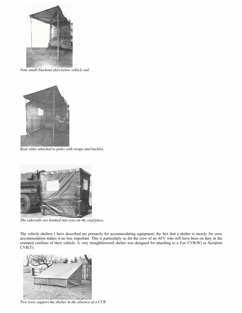
Note small blackout skirt below vehicle tail.
Rear sides attached to poles with straps and buckles.
The sidewalls are hooked into eyes on the roof piece.
The vehicle shelters I have described are primarily for accommodating equipment; the fact that a shelter is merely for crewaccommodation makes it no less important. This is particularly so for the crew of an AFV who will have been on duty in thecramped confines of their vehicle. A very straightforward shelter was designed for attaching to a Fox CVR(W) or ScorpionCVR(T).
Two trees support the shelter in the absence of a CVR.

Significantly more space can be created by a freestanding shelter such as with the FV432 in Command Post role. The shelterwas 12ft long x 9ft wide x 6ft 3in high and was normally fitted with four fluorescent lighting units.
FV432 in Command Post role.
The sturdiness of an armoured vehicle lends itself to the permanent fixing of a frame that can be extendedto support tentage. Two examples of this can be found in the Saracen family.
Extendable frame on the Armoured Command Vehicle (FV604).
Extendable frame on the much taller Armoured Command Post (FV610).
FV610 with penthouse at the rear and at the side of the vehicle. The rear shelter can act as a corridor to interconnect twovehicles.

A further development is to have an assembled shelter carried at the rear of an AFV. This is not only convenient but savesprecious time given that an AFV is likely to be near the front lines. Such a shelter was developed for the taller CVR(T)vehicles Sultan and Samaritan. The shelter made of polyurethane coated nylon and could be deployed by three men in fiveminutes.
The command post shelter showing the blackout skirts for fitting to the rear of the parent vehicle.
The shelter was 8ft long x 6ft wide x 6ft 8in high giving a floor area of 48 sq. ft. Studying this prototype shelter a series ofthree frames can be seen that are made of narrow tubing. The apex of the roof is 130 degrees whereas the apex of the Sultanroof is 165 degrees. In service the arrangements were much simpler, a single frame made of more substantial tubing wasmounted at the rear of the vehicle. On extending the frame, telescopic legs were released from the main frame.
A simple but substantial frame fitted to a Sultan.
Clearly quite a different shelter from the original prototype.
Sultan on the left with shelter and frame. Samaritan on the right, which in the end was not equipped with a shelter.
The most successful tentage of recent times is the command post (CP) shelter designed to fit behind a Land Rover. Oftenreferred to as a 9 x 9, this tentage is based on its approximate dimensions in feet. The 9 x 9 has acquired a high degree ofacceptance considering the structure was specifically intended to provide accommodation integrated with a Land Rover. Inrestored vehicle circles it is quite usual to see a 9 x 9 beside a vehicle whose owners are at the very least ambivalent towardsthe world of Land Rovers.

The origins of the 9 x 9 go back to a larger design manufactured by John Edgington & Co Ltd in the late 1960s. This frame tenthad a surface coverage of 13ft x 9 ft and was intended for use with vehicles such as a Land Rovers or Austin Gypsy. It isunfortunate that all the manufacturer’s promotional pictures show the later 9ft x 9ft shelter.
The 13ft x 9ft shelter was available in green, sand or white waterproofed canvas. This canvas must have been fairly flimsy asthe complete weight of the tent is 60.5kg whereas the smaller 9ft x 9ft weighs in at 80kg. The feature of the shelter is that it isfree standing being supported by a frame of light alloy tubing and differed from other vehicle shelters that relied on the vehiclefor support. Additional stability is provided by guys and the placing of sandbags or earth dug from drainage trenches aroundthe skirting at the base of the walls. The aperture at the front of the shelter incorporates a shroud that fastens to the Land Rovercanopy. A skirting attaches to the underside of the Land Rover to keep exhaust fumes out of the shelter. When the shelter isused independently of the Land Rover a roll up curtain is dropped down over the entrance.
The spacious accommodation inside what is claimed to be the 13ft x 9ft shelter.
At the rear of the shelter, two curtains can be tied back to provide wide access. Translucent windows are provided on thesidewalls but cannot be opened to allow in fresh air. Roll-down covers blackout the windows at night. A customised groundsheet and fireproof lining were also available. All the shelter components were carried in two large canvas bags and two mencould erect or dismantle the shelter in five minutes.
Length: 2.74m (9ft)Width at ground: 3.96m (13ft)Width at eaves: 2.74m (9ft)Height at ridge: 2.39m (7ft 10in)Height at eaves: 1.82m (6ft)Weight: 60.5kg (134lb)
The 13ft x 9ft seems not to have enjoyed much service use, presumably because it was unnecessarily large for its role and thecanvas too thin, although an inner tent lining was available. Other annoyances would have been the poor ventilation and theflimsy connectors to join the alloy frame together. The original cost of the main tent and frame was £67 10s 0d, the inner tentwas £26 10s 0d and groundsheet £11 10s 0d.
The 9ft x 9ft Mk 1 was a much more durable piece of kit. It entered service in 1969 and was made from canvas manufacturedfrom a corespun; cotton covered polyester duck fabric of ripstop construction. The canvas had a FWR finish (Flame retardant,Water repellent, Rot proof). The windows were now of a reinforced opaque material that could be rolled up for ventilation. Theshelter exit incorporated a blackout curtain. The frame was again made of light alloy poles, but the tubular connectors weremuch sturdier. Although we all refer to the shelter as a 9ft x 9ft, I have shatter the belief that this refers to its floor dimensions.In fact the real dimensions are 8ft 9in x 9ft 4in or in Eurospeak 2.7m x 2.8m. The full description is:
Shelter, Command Post and General Purpose 9ft x 9ft (2.7m x 2.7m) J1 8340-99-120-6653
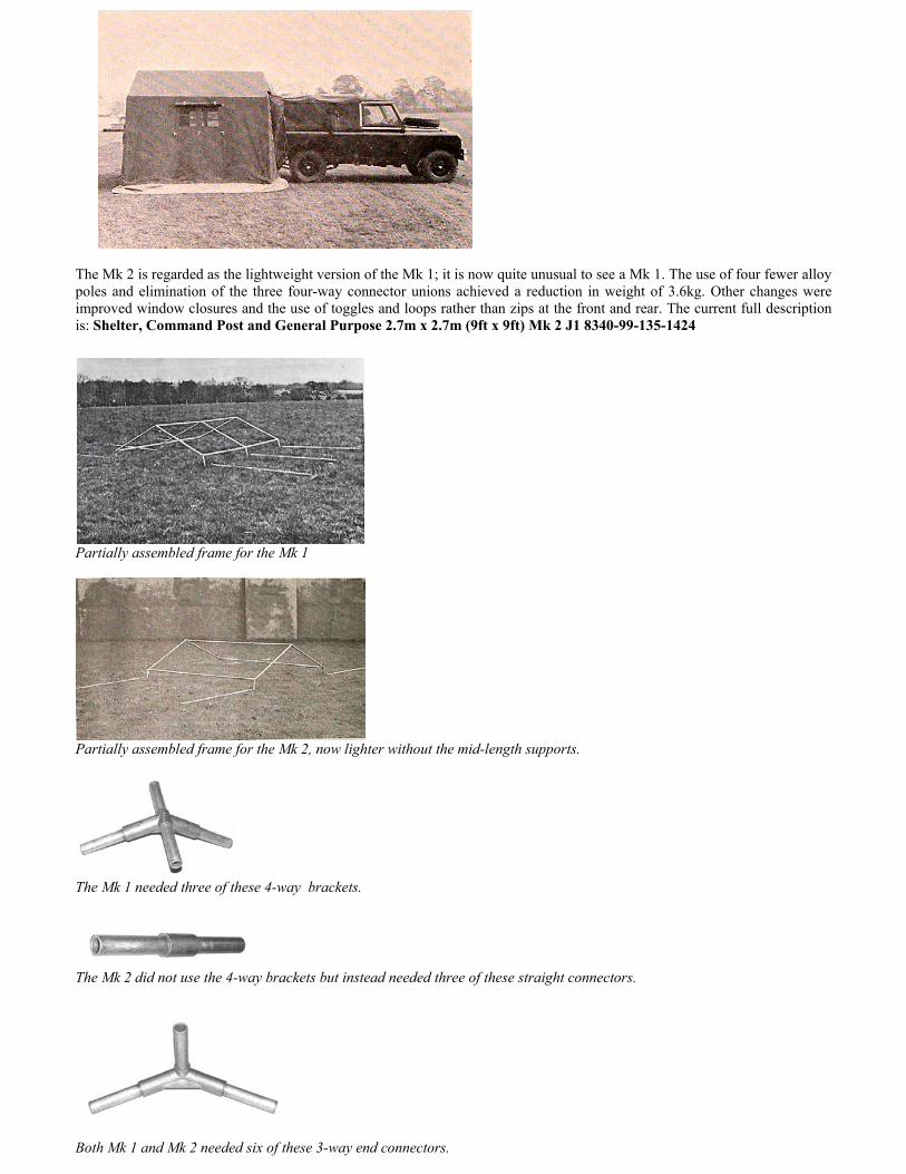
The Mk 2 is regarded as the lightweight version of the Mk 1; it is now quite unusual to see a Mk 1. The use of four fewer alloypoles and elimination of the three four-way connector unions achieved a reduction in weight of 3.6kg. Other changes wereimproved window closures and the use of toggles and loops rather than zips at the front and rear. The current full descriptionis: Shelter, Command Post and General Purpose 2.7m x 2.7m (9ft x 9ft) Mk 2 J1 8340-99-135-1424
Partially assembled frame for the Mk 1
Partially assembled frame for the Mk 2, now lighter without the mid-length supports.
The Mk 1 needed three of these 4-way brackets.
The Mk 2 did not use the 4-way brackets but instead needed three of these straight connectors.
Both Mk 1 and Mk 2 needed six of these 3-way end connectors.

It is unfortunate that the current user handbook for the Mk 2 uses the wrong photo to illustrate the frame! It uses a photo of aMk 1 frame, which is more complex. I just wonder how many soldiers had been trying to put the thing up ‘by the book’ andwere frustrated to find major components apparently missing! The picture for parts list is also wrong. It illustrates the four-poleconnector, which was only used on the Mk 1. The parts list is almost correct but doesn’t make sense with the illustrations used.Yet the 1972 user handbook used the correct illustrations although it does make a dyslexic error for one of the part numbers. Itappears that the author of the current Joint Service user handbook copied large sections from the user handbook for the Mk 1rather than upgrade the last publication issued on the Mk 2 but even this has a few errors! It is amazing that equipment assimple as a tent can have so many errors perpetuated, it is really remarkable that vehicle publications have so few errors. Irecently purchased the current user handbook from the MOD, as this was published in 1981 it is disappointing that there havebeen no amendments to all these glaring errors!
The correct illustration for the complete Mk2.
Item Catalogue Number Designation Quantity
A J1/8340-99122-5844 Shelter Canvas 1B J1/8340-99-120-6661 Bracket Shelter Frame 6C J1/8340-99-122-6574 Connector Shelter Frame 3D F1/5120-99-910-4703 Hammer Head 1E J1/8340-99-122-6575 Wall Member Shelter Frame 4F J1/8340-99-122-6657 Roof Member Shelter Frame (ridge & eave) 6G J1/8340-99-120-6658 Roof Member Shelter Frame (rafter) 4H J1/8340-99-132-0028 Pin Tent 12 inches 16I J1/8340-99-120-6655 Bag Tent 1J J1/8340-99-122-5824 Bag Shelter Frame Parts (tubes) 1K J1/8340-99-120-6662 Bag Shelter Frame Parts (brackets) 1L J1/8340-99-120-7079 Bag Tent 1
The Domestic Management Code (DMC) precedes the NATO Stock Number (NSN). F1 is not an error; this is the DMC forHand Tools (Non-Powered), whereas J1 is the DMC for Tents, Shelters & Camping Equipment.
Item E originally engaged the ground with a pointed end fitted with a depth-limiting disc.
The later version had a flat end and was just terminated by a rectangular plate.
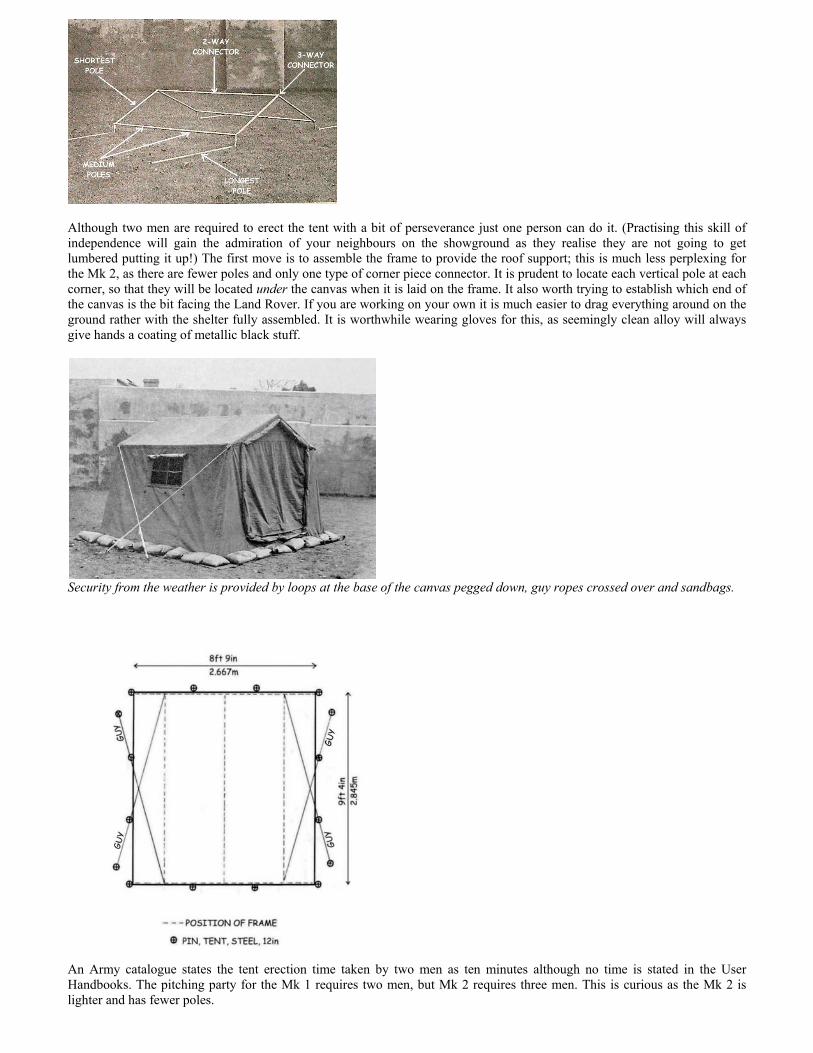
Although two men are required to erect the tent with a bit of perseverance just one person can do it. (Practising this skill ofindependence will gain the admiration of your neighbours on the showground as they realise they are not going to getlumbered putting it up!) The first move is to assemble the frame to provide the roof support; this is much less perplexing forthe Mk 2, as there are fewer poles and only one type of corner piece connector. It is prudent to locate each vertical pole at eachcorner, so that they will be located under the canvas when it is laid on the frame. It also worth trying to establish which end ofthe canvas is the bit facing the Land Rover. If you are working on your own it is much easier to drag everything around on theground rather with the shelter fully assembled. It is worthwhile wearing gloves for this, as seemingly clean alloy will alwaysgive hands a coating of metallic black stuff.
Security from the weather is provided by loops at the base of the canvas pegged down, guy ropes crossed over and sandbags.
An Army catalogue states the tent erection time taken by two men as ten minutes although no time is stated in the UserHandbooks. The pitching party for the Mk 1 requires two men, but Mk 2 requires three men. This is curious as the Mk 2 islighter and has fewer poles.
The time taken for dismantling and packing is the same as for assembly. The biggest challenge for repacking is to get the maincanvas in its carrying bag. It will appear to have grown to twice the size that it was when it came out of the bag! If the canvasis wet it should not be packed in its bag. Not only will it eventually rot but also at the very least when you next use it there willbe an unpleasant smell. From a practical point of view not only will the wet canvas be heavy but it will even less willing to beforced into its bag. The shelter is dismantled in the reverse order of assembly. The crucial part is the folding of the canvas.
1. Fold the canvas in half.2. Lay it flat on the ground.3. Fold ends on to roof and wall.4. Fold walls to ridge in three equal folds.5. Finally, roll to form the smallest bundle. Sitting on it helps, then try to squeeze it into the bag.
Despite this being a promotional picture from the manufacturer, the guys have not been positioned correctly. The arrangementshown gives no additional stability and presents a tripping hazard.
The principle manufacturer was John Edgington & Co Ltd. The company became Black & Edgington (Sidcup) Ltd, whichspawned an export department Benjamin Edgington (Sidcup) Ltd. The company further evolved into The North Face(Scotland) Ltd, which at one time claimed to be the largest UK-based manufacturer of tents. But like so many UK basedindustries, an Internet search reveals nothing of their former glory.
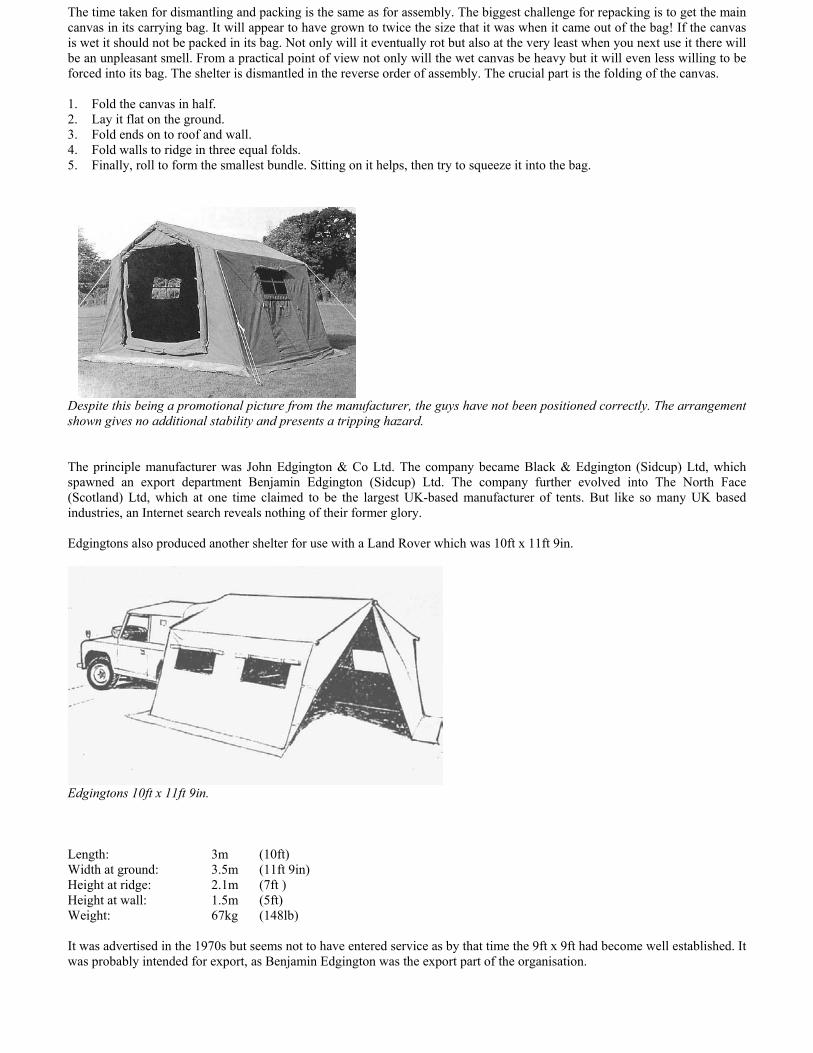
Edgingtons also produced another shelter for use with a Land Rover which was 10ft x 11ft 9in.
Edgingtons 10ft x 11ft 9in.
Length: 3m (10ft)Width at ground: 3.5m (11ft 9in)Height at ridge: 2.1m (7ft )Height at wall: 1.5m (5ft)Weight: 67kg (148lb)
It was advertised in the 1970s but seems not to have entered service as by that time the 9ft x 9ft had become well established. Itwas probably intended for export, as Benjamin Edgington was the export part of the organisation.

Although not intended for accommodation there was a vehicle maintenance shelter particularly suitable for a Land Rover.Anyone who has broken down in they rain can appreciate its value although the lack of all round light is a limiting factor.
This shelter’s stability in wind is doubtful.
Officially known as Shelter, Portable, No.21 J1 83490-99-125-1464. It can be seen that the last seven digits of the NSN areplaced chronologically between the Mk 1 and Mk 2 9ft x 9ft shelters, given that the Shelter, Portable, No.21 was in service in1973 it seems about right. As this is just a single canvas sheet it is surprising that three men would take as long as ten minutesto erect it, although dismantling was only reckoned to take five minutes. The canvas sheet is supported at one end by thevehicle and it was said to be supported at the other by three tubular steel poles. Given that this is a rectangular canvas it seemsextraordinarily unbalanced to have only three poles rather than four. I think the explanation is that the person writing thetechnical details has been misled by the photograph. Here clearly there are only three poles, but I feel there should have beenfour. The missing pole and its guy rope would certainly explain the poor stability of the shelter in the wind.
Width: 15ft (4.6m)Length: 13ft 6in (4.1m)Height: 6ft 3in (1.9m)Area: 202.5 sq ft (18.8 sq m)Weight: 87lb (39.4kg) (canvas, poles, pegs & guys)
One of the smallest framed shelters must surely be the Shelter, Servicing, Helicopter, Tail Rotor, Wessex. The shelter wassupported on a light alloy frame and the floor was a platform mounted above the tilt of a Land Rover.
The top of the Land Rover can just be seen under the shelter.
Width: 4ft 6in (1.3m)Length: 7ft 6in (2.2m)Height: 10ft (3m)Area: 23sq ft (2.2 sq m)Weight: 80lb (36.2kg) (Canvas and Frame)
It must have been a fiddly thing to erect as four men needed twenty minutes to complete the task. It is not unusual to find RAFLand Rovers with a roof-mounted platform.
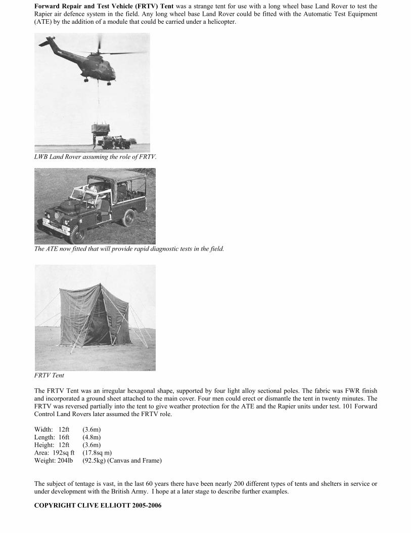
Forward Repair and Test Vehicle (FRTV) Tent was a strange tent for use with a long wheel base Land Rover to test theRapier air defence system in the field. Any long wheel base Land Rover could be fitted with the Automatic Test Equipment(ATE) by the addition of a module that could be carried under a helicopter.
LWB Land Rover assuming the role of FRTV.
The ATE now fitted that will provide rapid diagnostic tests in the field.
FRTV Tent
The FRTV Tent was an irregular hexagonal shape, supported by four light alloy sectional poles. The fabric was FWR finishand incorporated a ground sheet attached to the main cover. Four men could erect or dismantle the tent in twenty minutes. TheFRTV was reversed partially into the tent to give weather protection for the ATE and the Rapier units under test. 101 ForwardControl Land Rovers later assumed the FRTV role.
Width: 12ft (3.6m)Length: 16ft (4.8m)Height: 12ft (3.6m)Area: 192sq ft (17.8sq m)Weight: 204lb (92.5kg) (Canvas and Frame)
The subject of tentage is vast, in the last 60 years there have been nearly 200 different types of tents and shelters in service orunder development with the British Army. I hope at a later stage to describe further examples.
COPYRIGHT CLIVE ELLIOTT 2005-2006