climatic™ 60 user manual
TRANSCRIPT

CLIMATIC™ 60
ECOLEAN™
NEOSYS™
User manual
CL60 AC-CHILLER-IOM-0512-E
Air cooled chiller


• 1 •
CLIMATIC™ 60
222
2
345
68
1013171920212223242526283033
34
3537394446
65
CL60-AC CHILLER-IOM-0512-E
CONTROL MANUALRef : CL60-AC CHILLER-IOM-0512-E
TABLE OF CONTENTS
AIR COOLED CHILLER
All the technical and technological information contained in this manual, including any drawing and technical descriptions provided by us, remain the property of Lennox and must not be utilised (except in operation of this product), reproduced, issued to or made available to third parties without the prior written agreement of Lennox.
INTRODUCTIONCLIMATIC™ 60 controllerCompatibilityWarning
OVERVIEWSCHEDULING
Scheduling zoneScheduling modeScheduling zone anticipation
COMPONENTSCompressorCondenser fanFan SMART ACOUSTIC SYSTEM™Water evaporatorChangeover heating/cooling modeCoil defrostFree coolingElectronic expansion valveElectrical heaterPower factor correctorPump evaporator managementPump evaporator fl ow controlPump condenser managementPump condenser fl ow controlFree input/outputON/OFF controlReal time clock
COMMUNICATIONMaster / slaveDS60 displayDC60 advanced display or DS60 displayBMSAlarms
APPENDIX

• 2 • CL60-AC CHILLER-IOM-0512-E
INTRODUCTION
OVERVIEW
pLan bus Fieldbus bus
BMS bus
CLIMATIC™ 60 CONTROLLERThe new generation of microprocessor based control, CLIMATIC™ 60 may be fi tted to the LENNOX chiller range. It inherits 20 years of technology and fi eld operating experience from its predecessors the CLIMATIC™ 1, CLIMATIC™ 2 and CLIMATIC™ 50.LENNOX has found the latest hardware technology available on the market place and developed software specifi cally designed for chiller applications, maximising the LENNOX unit’s effi ciency and performance.
COMPATIBILITYThis documentation is compatible with the chiller programs:• NEOSYS / ECOLEAN ranges from software version CH060 STD - Vers. 2 - Rev 0.0.
WARNINGAny parameter modifi cation should be carried out by trained and licensed competent technician. Before start-up or restart of a unit controlled by the CLIMATIC™ 60, it is mandatory to check adequacy between CLIMATIC™ 60 and the unit with its options. In case of wrong parameters, the inputs / outputs connections could be incorrect and may create some operation problems for the units and ultimately breakdowns. LENNOX cannot be held responsible for any claims on the units due to a wrong parameters sequence or a parameters modifi cation carried out by non competent technicians. In this case, the warranty will be legally null and void.
DS60 MENUThroughout the document, all parameters and set points which are explained are given with their address menu where they will be visible on the display DS60.Example, the customer set point explained in the AIR MANAGEMENT § is indicated with the reference (2222), meaning that this set point may be changed at the address (2222) with the display DS60. The full list of parameters and set point is given at the end of the document.Only the addresses of parameters accessibles at the «User» level (2xxx) are identifi ed in the document - Set point accesible at the «Expert» level (3xxx) with password are mentioned only if they are not accessible at the «User» level

• 3 •
12h/0h
6h
9h 15h3h
24h/12h
18h
21h
(2131):
(2141):
(2142):
(2143):
(2144):
(2145):
(2146):
(2147):
CL60-AC CHILLER-IOM-0512-E
SCHEDULING
SettingsThe different settings to adjust the scheduling zone are available in the menu:
Note: the visibility of the settings (2141) to (2147) depend on the settings (2131). The zones not used are hidden.
The following factory setting is applied- Zone 0 00h00 Monday to Sunday- Zone 1 06h00 Monday to Sunday- Zone 2 22h00 Monday to Sunday
Number of zone desired,
Start time of zone 0 set to 00h00 to start each day
starts time of zone 1 adjustable every day from Monday to Sunday
starts time of zone 2 adjustable every day from Monday to Sunday
starts time of zone 3 adjustable every day from Monday to Sunday
starts time of zone 4 adjustable every day from Monday to Sunday
starts time of zone 5 adjustable every day from Monday to Sunday
starts time of zone 6 adjustable every day from Monday to Sunday
Zone 2
Zone 0 Zone 3
Zone 4Zone 1
Zone 6
Zone 5
Monday
Sunday
SCHEDULING ZONE
FunctionThe CLIMATIC™ 60 is provided by a real time clock which offers solutions to specify a weekly schedule.
DescriptionThe CLIMATIC™ 60 schedule manages up to 7 different clock zones per day from 00h00 to 24h00 and from Monday to Sunday. The zone can start at different time each day of the week in order to optimise the operating of the unit.

• 4 •
(2132):
(2151):
(2152):
(2153):
(2154):
(2155):
(2156):
(2157):
12h/0h
6h
9h 15h3h
24h/12h
18h
21h
CL60-AC CHILLER-IOM-0512-E
SCHEDULING
SettingsThe different settings to adjust the scheduling mode are available in the menu:
Note: the visibility of the settings (2151) to (2157) depend on the settings (2132). The modes not used are hidden.
The following factory setting is applied- Day Mode on Zone 0 from Monday to Sunday- Day Mode on Zone 1 from Monday to Sunday- Day Mode on Zone 2 from Monday to Sunday
Number of mode desired
mode used during the period of zone 0 adjustable every day from Monday to Sunday
mode used during the period of zone 1 adjustable every day from Monday to Sunday
mode used during the period of zone 2 adjustable every day from Monday to Sunday
mode used during the period of zone 3 adjustable every day from Monday to Sunday
mode used during the period of zone 4 adjustable every day from Monday to Sunday
mode used during the period of zone 5 adjustable every day from Monday to Sunday
mode used during the period of zone 6 adjustable every day from Monday to Sunday
SCHEDULING MODE
FunctionThe CLIMATIC™ 60 is able to control different modes for each zone in order to optimise the operating of the unit.
DescriptionThe CLIMATIC™ 60 can manage up to 4 different modes. - Night / Day / Day I / Day II
Day mode
Night mode Day mode
Day I modeDayI mode
Night mode
Day II mode
Monday
Sunday
• 5 •CL60-AC CHILLER-IOM-0512-E
SCHEDULING
(2142):
(2161):
(2162):
(2161):
(2162):
SCHEDULING ZONE ANTICIPATION
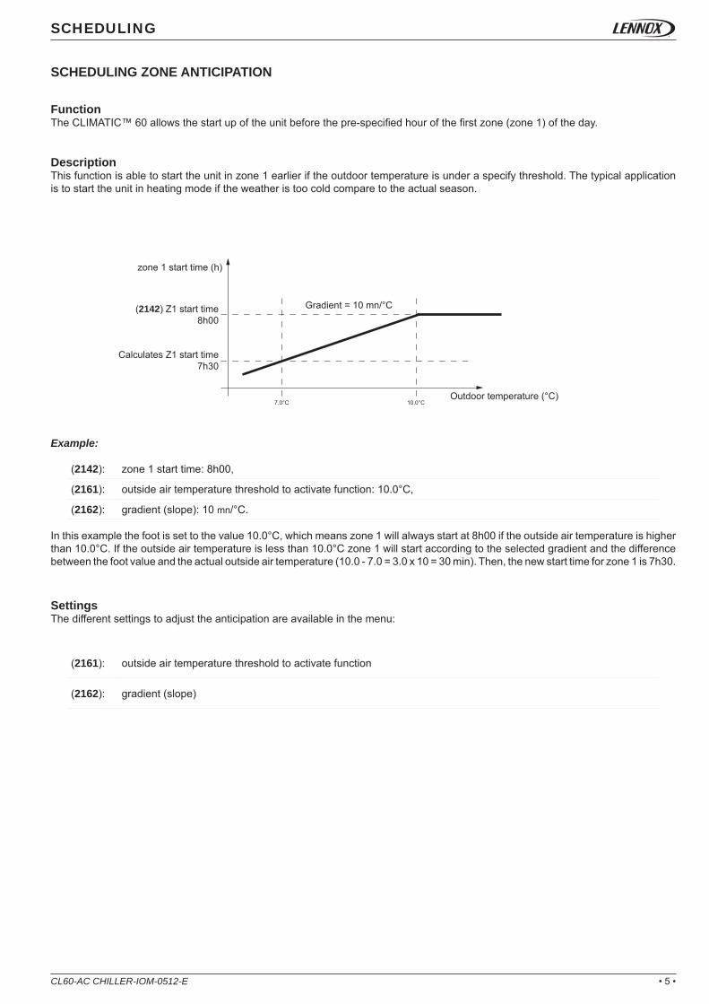
FunctionThe CLIMATIC™ 60 allows the start up of the unit before the pre-specifi ed hour of the fi rst zone (zone 1) of the day.
DescriptionThis function is able to start the unit in zone 1 earlier if the outdoor temperature is under a specify threshold. The typical application is to start the unit in heating mode if the weather is too cold compare to the actual season.
Example:
zone 1 start time (h)
Outdoor temperature (°C)
(2142) Z1 start time8h00
Calculates Z1 start time7h30
Gradient = 10 mn/°C
zone 1 start time: 8h00,
outside air temperature threshold to activate function: 10.0°C,
gradient (slope): 10 mn/°C.
In this example the foot is set to the value 10.0°C, which means zone 1 will always start at 8h00 if the outside air temperature is higher than 10.0°C. If the outside air temperature is less than 10.0°C zone 1 will start according to the selected gradient and the difference between the foot value and the actual outside air temperature (10.0 - 7.0 = 3.0 x 10 = 30 min). Then, the new start time for zone 1 is 7h30.
SettingsThe different settings to adjust the anticipation are available in the menu:
outside air temperature threshold to activate function
gradient (slope)

• 6 •
1
1
1
1
1
1
1
1
2
2
2
2
3
3
3
3
2
2
2
2
3
3
3
3
12h/0h
6h
9h 3h
24h/12h
18h
21h 15h
1, ., .
., 2, .
1, 2, .
., ., 3
1, ., 3
., 2, 3
1, 2, 3
CL60-AC CHILLER-IOM-0512-E
COMPONENTS
COMPRESSOR
FunctionThe CLIMATIC™ 60 manages the compressor(s) according to the outlet temperature demand and engages the number of compressor calculated to reach the water set point.
DescriptionThe CLIMATIC™ 60 offers possibilities to disable some compressor(s) on the circuit. Note this opportunity can also be done by dry contact (Refer to the “Free input/output” paragraph).
The compressors allowed to run can be pre-specifi ed according to the scheduling and can take different values for each schedule mode (Night, Day, Day I, Day II, BMS).
Setting(3421)
Compressor on circuit(case of 3 compressors)
NO
Moreover, the circuit priority can be specifi ed (for units with 2 circuits)
“Auto”:The CLIMATIC™ 60 decides the priority of the circuit which starts fi rst. Note that the priority may be swapped only when all the compressors are stopped in order to optimise the operating hours of the two circuits.
C ModeC1: 1,2,3C2: 1,2,3 A Mode
C1: 1,.,.C2: 1,.,.
C ModeC1: 1,2,3C2: 1,2,3
B ModeC1: 1,2,.C2: 1,2,.
B ModeC1: 1,2,.C2: 1,2,.
D ModeC1: .,.,3C2: .,.,3
D ModeC1: .,.,3C2: .,.,3

• 7 •
(3431):
(3432):
(3435):
CL60-AC CHILLER-IOM-0512-E
COMPONENTS
The compressor is subject to various operating time in order to prevent from damage operating.• The minimum ON time of the compressor is fi xed to 1 minute,• The minimum OFF time of the compressor is fi xed to 1 minute,• The minimum between 2 starts of the same compressor is fi xed to 5 minutes.
Compressor demand
Compressor demand
Compressor demand
Compressor output
Compressor output
Compressor output
SettingsThe different settings to confi gure the compressors are available in the menu:
“Priority C1”:The priority is fi xed to circuit 1, which means circuit 1 starts fi rst and stops the last.
“Priority C2”:The priority is fi xed to circuit 2, which means circuit 2 starts fi rst and stops the last.
Enable of the compressor(s) on circuit 1
Enable of the compressor(s) on circuit 2
Priority of the circuit rotation.

• 8 •
(3549) (3548)
CL60-AC CHILLER-IOM-0512-E
COMPONENTS
CONDENSER FAN
FunctionThe CLIMATIC™ 60 is used to maintain the high pressure as stable as possible in order to increase the performance of the unit.
DescriptionThe CLIMATIC™ 60 has 2 different fan managements according to the type of unit:
ECOLEAN™ (without fan speed inverter)The CLIMATIC™ 60 manages 2 speeds on the fan (low and high speed).
NEOSYS™ standard unit (standard version without fan speed inverter)The condensing temperature is reached according to the set point selected in the menu (3545). The fans are managed individually except for the fans which are common for the two circuits.In order to optimise the reactivity of the system at the startup of the circuit, an anticipation of the fan(s) is forced during the fi rst 30s according to the outside air temperature.
Example: Case of unit with 4 condenser fans.
Outside air temperature (°C
Stopped
Stopped
HP pressure (Bar)
Low speed
Low speed
High speed
High speed
Cooling mode
Heating mode
Outside air temperature (°C)
Compressor pressure demand (%)
Fan anticipation (%)
Fan stages

• 9 •
(3545):
CL60-AC CHILLER-IOM-0512-E
COMPONENTS
Time
Temperature HP (°C)
Fan capacity (%)
Condensing set point
SettingsThe different settings to adjust the condensing control are available in the menu:
ECOLEANTM NEOSYS™ (with fan speed inverter)A fan inverter controlled by a PID algorithm is used to adjust the fans speed variation. Fan's startup anticipation is forced as for the NEOSYSTM standard unit.
In order to optimise the performance of the unit, the condensing temperature is set according to outside air temperature and tries to maintain a delta of 12°C (only for unit with electrionic expansion valve).
Note: this functionality can be disabled if the selected setting (3545) is different from the factory value. In this case the condensing set point is the new selected value.
Outside air temperature (°C)
Condensing set point (°C)
Condensing set point temperature.

• 10 • CL60-AC CHILLER-IOM-0512-E
COMPONENTS
FAN SMART ACOUSTIC SYSTEM™
FunctionThe CLIMATIC™ 60 controls the fan speed limited by the Smart Acoustic System™ which allows progressive adaptation of the unit to the building load while respecting the noise level constraints and the operating limits.
DescriptionThe maximum sound level and the fan strategies can be adjusted according to the schedule mode in order to benefi t from the different modes “Auto”, “ Auto Quiet” and “Quiet” operation as well as in heating or cooling mode.The acoustic mode offers 2 possibilities to manage the condenser fan:
"Auto Quiet”In this mode, the fan capacity is limited according to the desired sound level. For fan using low / high speed, the high speed is locked. In case of condensing temperature too high, the CLIMATIC™ 60 unlocks the limit or the high speed to prevent from unloading compressor.
Outside air temperature (°C
Outside air temperature (°C
Stopped
Stopped
HP pressure (Bar)
Low speed
Low speed
High speed
High speed
Cooling mode
Heating mode
Fan speed (%)
Maximum = (3544)
Maximum = (3544)
Fan capacity (%)
Maximum = 100%
Maximum = 100%
Temperature HP (°C)(3545) Condensing set point
(3442) Unloading set point
Cooling mode
Heating mode
• 11 •
12h/0h
6h
9h 3h
24h/12h
18h
21h 15h
CL60-AC CHILLER-IOM-0512-E
COMPONENTS
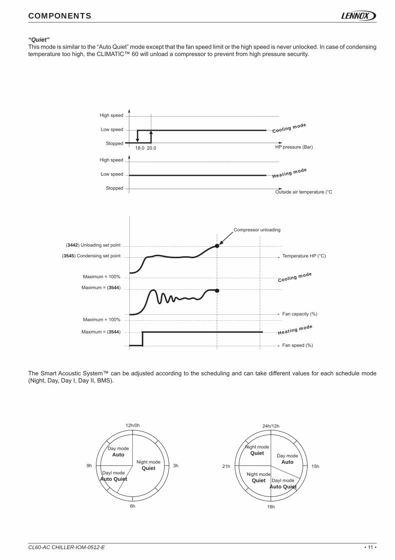
“Quiet”This mode is similar to the “Auto Quiet” mode except that the fan speed limit or the high speed is never unlocked. In case of condensing temperature too high, the CLIMATIC™ 60 will unload a compressor to prevent from high pressure security.
The Smart Acoustic System™ can be adjusted according to the scheduling and can take different values for each schedule mode (Night, Day, Day I, Day II, BMS).
Outside air temperature (°C
Stopped
Stopped
HP pressure (Bar)
Low speed
Low speed
High speed
High speed
Cooling mode
Heating mode
Fan speed (%)
Maximum = (3544)
Maximum = (3544)
Fan capacity (%)
Maximum = 100%
Maximum = 100%
Temperature HP (°C)
Compressor unloading
(3545) Condensing set point
(3442) Unloading set point
Cooling mode
Heating mode
Day modeAuto
Night modeQuiet
Day modeAuto
DayI modeAuto Quiet
DayI modeAuto Quiet
Night modeQuiet
Night modeQuiet

• 12 •
(3543):
(3544):
12h/0h
6h
9h 3h
24h/12h
18h
21h 15h
CL60-AC CHILLER-IOM-0512-E
COMPONENTS
SettingsThe different settings to adjust the acoustic mode are available in the menu:
Acoustic mode
Maximum sound level noise (except for fan with low / high speed)
Mode Day89dBA
Mode Night84dBA
Mode Day89dBA
Mode Day I86dBA
Mode Day I86dBA
Mode Night84dBA
Mode Night84dBA

• 13 •
12h/0h
6h
9h 3h
24h/12h
18h
21h 15h
CL60-AC CHILLER-IOM-0512-E
COMPONENTS
WATER EVAPORATOR
FunctionThe CLIMATIC™ 60 controls the chilled or heat temperature according to the specifed set point. The desired set point can be set by different solutions.
DescriptionThe CLIMATIC™ 60 offers various possibilities to specify the water evaporator set point.
Dynamic valueThe CLIMATIC™ 60 determines the appropriate water set point according to the outside temperature in order to optimise the energy consumption. This method requires to pre-defi ne 2 different water set points corresponding to 2 outside temperatures.
Fix valueIn this case the outside temperature has no effect on the water set point and the two set points must be set at the same value.
The cooling and heating set points can be pre-specifi ed according to the scheduling and can take different mode for each schedule mode (Night, Day, Day I, Day II, and BMS)
Outside air temperature (°C)
Outside air temperature (°C)
Outside air temperature (°C)
Outside air temperature (°C)
Cooling set point (°C)
Cooling set point (°C)
Heating set point (°C)
Heating set point (°C)
ModeDay
07.0°C NightMode
13.0°C
ModeDay
07.0°C
ModeDay
07.0°C
ModeDay
07.0°C
NightMode
13.0°C
ModeDay I
09.0°C

• 14 • CL60-AC CHILLER-IOM-0512-E
External current 4/20mA signalIn this case the actual set point is calculated according to the analog input current. Menus (2238), (2239), (2248) et (2249) defi ned water temperature set points according to signals 4mA and 20mA
Current input signal4/20 mA
Current input signal4/20 mA
Cooling set point (°C) Heating set point (°C)
COMPONENTS
Second external set pointIn this case the actual set point is specifed by one of the two set points. The fi nal set point depends on the status of the digital dry contact allocated to this function.
External current 4/20 mA offsetIn this case the set point is set by one of the previous solution and can be adjusted with an offset of +/- 1.0°C.
Digital input contact
Current inpu signal4/20 mA
Digital input contact
Current inpu signal4/20 mA
Cooling set point (°C)
Open OpenClosed Closed
Cooling set point (°C)
Actual set point Actual set point
Heating set point (°C)
Heating set point (°C)

• 15 •CL60-AC CHILLER-IOM-0512-E
COMPONENTS
DC60 terminalThe water set point is adjustable directly by the DC60. If the read set point is different from the one calculated by the BM60, the new set point is set by the DC60 during the actual zone. Each time the zone is changing, the DC60 set point is overwriten by the CLIMATICTM60 set point.
BMS valueThe CLIMATIC™ 60 receives the water set point from the BMS. Refers to the “BMS” paragraph for more details.
SettingsThe different settings to adjust the water evaporator set points are available in the menu:
Cooling mode• (2236) : minimum outside air temperature corresponding to the water evaporator set point (2238) (used only for dynamic set point),• (2237) : maximum outside air temperature corresponding to the water evaporator set point (2239) (used only for dynamic set point),• (2238) :
* Dynamic set point: desired water evaporator temperature set point corresponding to outside air temperature (2236)* Fix set point: desired water evaporator temperature set point.* External current 4/20 mA signal: water evaporator temperature set point corresponding to a current signal of 4 mA.* Second external set point: fi rst water evaporator temperature set point corresponding to an opened dry contact.
• (2239) : * Dynamic set point: desired water evaporator temperature set point corresponding to outside air temperature (2237),* Fix set point: desired water evaporator temperature set point.* External current 4/20 mA signal: water evaporator temperature set point corresponding to a current signal of 20 mA.* Second external set point: second water evaporator temperature set point corresponding to a closed dry contact.
Heating mode• (2246) : minimum outside air temperature corresponding to the water evaporator set point (3248) (used only for dynamic set point),• (2247) : maximum outside air temperature corresponding to the water evaporator set point (3249) (used only for dynamic set point),• (2248) :
* Dynamic set point: desired water evaporator temperature set point corresponding to outside air temperature (2246),* Fix set point: desired water evaporator temperature set point.* External current 4/20mA signal: water evaporator temperature set point corresponding to a current signal of 4 mA.* First external set point: fi rst water evaporator temperature set point corresponding to an opened dry contact.
• (2249) : * Dynamic set point: desired water evaporator temperature set point corresponding to outside air temperature (2247),* Fix set point: desired water evaporator temperature set point.* External current 4/20mA signal: water evaporator temperature set point corresponding to a current signal of 20 mA.* Second external set point: second water evaporator temperature set point corresponding to a closed dry contact.

• 16 •
1
1
1
1
1
1
1
1
1
1
2
2
2
2
2
2
2
2
2
2
0 0 0 0
1 8.54 30.8 7.0 + 30.8*5.0/100
2 10.80 61.6 7.0 + 2*30.8*5.0/100
3 11.04 80.8 7.0 + (19.2+2*30.8)*5.0/100
4 12.00 100.0 7.0 + 2*(19.2+30.8)*5.0/100
CL60-AC CHILLER-IOM-0512-E
COMPONENTS
ControlThe CLIMATIC™ 60 adjusts and holds the fl uid outlet temperature as close as possible to the set point, by controlling the number of compressor stages depending on the thermal load of the system. The controller constantly calculates the required capacity to reach the temperature set point. This variable is called “CAPACITY FACTOR” (CF) and its value can vary from 0 to 100%. It is directly linked to the number of control stages of the unit. Thus for a unit with 4 stages of regulation, the CF will start and stop a stage with the following values: ~0-25-50-75-100%. It then evolves following the principles detailed in the diagram.
In order to anticipate, the reference point is recalculated each time the difference between air temperature and set point reaches a minimum or a maximum.Moreover the inlet temperature is used to limit the capacity factor to prevent from too slow reactivity of outlet capacity factor of the unit.
Example: • Unit EAC 2104: cooling capacity: 210KW with:
* C1.Cp1 = 19.2%,* C1.Cp2 = 30.8%,* C2.Cp1 = 19.2%,* C2.Cp2 = 30.8%.
• Maximum delta T° (inlet - outlet) at full load: setting (3261) = 5.0°C.• Outlet water evaporator temperature set point: setting (3238) = (3239) = 7.0°C.
Difference between the outlet water temperature and the
set point
Water temperaturecan change
CF FROZEN
CF FROZEN
FAST SLOW SLOW FAST
CF INCREASES(starts more capacity stages)
CF DECREASES(removes capacity stages)
Stage Minimum inlet temp. (°C)
Maximum capacity factor
(%)Expression Compressor
ON circuit 1 Compressor ON circuit 2

• 17 •
12h/0h
6h
9h 3h
24h/12h
18h
21h 15h
CL60-AC CHILLER-IOM-0512-E
COMPONENTS
CHANGEOVER HEATING/COOLING MODE
FunctionThe CLIMATIC™ 60 controls the changeover mode (for reversible units only) to specify the appropriate demand on heat or chilled water production.
DescriptionThe changeover can also be pre-specifi ed according to the scheduling and can take different mode for each schedule mode (Night, Day, Day I, Day II, BMS).
The changeover mode can be set by different solutions:
Automatically:The CLIMATIC™ 60 determines the appropriate production of water according to the outside temperature and moves automatically the unit from cooling to heating mode and heating to cooling mode.
If the outside temperature is below the setting value (2225) or (3225), the unit will operate as a heat pump.If the outside temperature is over the setting value (2226) or (3226), the unit will operate as a chiller.
Manually:The changeover mode is forced for each schedule mode. The various modes available are “Cool” mode, “Heat” mode or "Dead zone". In this case the outside temperature has not effect on the changeover mode.
Remotely:The changeover mode is set according to a remote dry contact connect on a free custom digital input. In this case the unit swaps in cooling or heating mode according to the status of the digital input. Please refer to the paragraph “Free Input / Output” for more details.
Changeover mode
Heating mode
Dead zone
Cooling mode
Outdoor temperature (°C)
Mode Day IAuto
Mode NightDead zone
Mode Day IAuto
Mode Day IAuto
Mode DayChauffage
Mode NightDead zone
Mode Day IAuto

• 18 • CL60-AC CHILLER-IOM-0512-E
Terminal DC60:The changeover mode (cool / heat) can be modifi ed by the terminal DC60 by pressing the “mode” button.
When the “Auto” mode is selected, icon “Cool” or “Heat” or "no icon" is displayed to signal the current operating mode. Due to communication delay, after pressing the “mode” button it is advised to wait few seconds to refresh of the icon on the display. After the unit start-up,the "mode" button pressure is ignored during a few seconds.
COMPONENTS
→ Heat → Cool → Auto → Dead zone
SettingsThe different settings to adjust the changeover mode are available in the menu: • (2224) : changeover mode (Cool, Heat, Auto, Dead zone) for each schedule mode (Night, Day, Day I, Day II, and BMS).• (2225) : minimum outside temperature to swap to heating mode. (only if (2224) =“Auto”).• (2226) : maximum outside temperature to swap to cooling mode. (only if (2224) =“Auto”).

• 19 •CL60-AC CHILLER-IOM-0512-E
COMPONENTS
COIL DEFROST
FunctionThe CLIMATIC™ 60 manages defrost procedure to avoid ice on the evaporator coil in heating pump mode (winter season).
DescriptionTo avoid the icing of the external air exchanger during winter operating, it’s necessary to reverse the refrigerant cycle. There are 2 defrost mode:• cyclic mode,• dynamic mode (not available in the software CH060 vers.2 - rev.0.0).
The defrost procedure is activated if the following conditions are met during 1 minute:• the outside air temperature is ≤ (3562),• one of the compressor(s) on the circuit has been running for a time ≥ (3564) since the last defrost,• the saturation temperature is ≤ (3563).
The defrost procédure is characterized by the following steps:1. start electrical heater during 2 min (chiller with electrical heater only),2. stop the compressors on the concerned circuit,3. wait for 5 s 4. reverse the 4WV5. start all compressors on the circuit (if the outlet T° is not too low),6. start all condenser fans when the HP ≥ 50.0°C,7. stop all condenser fans when the HP ≤ 42.0°C,8. repeat the steps 6. to 7. 3 times9. stop the compressors of the circuit,10. wait for 1 min to equalise the pressure in the circuit,11. start the fans 30s to dry the condensenser12. end of procedure; restart the unit in heating mode.13. reverse the reversing valve after 5 s if ΔP>2 bar.
Note• In case of alarm on the circuit during the defrost procedure, the defrosting is cancelled.• If the HP pressure doesn’t reach 50°C after 6 min, during the step 6, the defrost procedure is cancelled.• During the step 4 the compressor(s) could not start in order to not decrease too much the water temperature of the system.
SettingsThe different settings to adjust the defrosting procedure are available in the menu: • (3561): defrost mode (cyclic, dynamic),• (3562): minimum of outside air temperature to enable defrost procedure,• (3563): critical saturation temperature to enable defrost procedure• (3564): minimum of interval time to enable defrost procedure.
Outlet water temperature (°C)
Compressor in defrost

• 20 •
(3166):
CL60-AC CHILLER-IOM-0512-E
COMPONENTS
FREE COOLING
FunctionThe freecooling option ensures to reduce the electrical consumption using the outside air temperature to produce cool water.
DescriptionThe freecooling uses water coil with helicoids fans controled by the CLIMATIC™ 60. The freecooling has a higher priority face to the compressors. Once the freecooling capacity is over 95% for 2 min, the compressors can be engaged if necessary in order to reach the cooling set point. If the freecooling capacity decreases below 90%, the capacity factor of the compressor(s) capacity is locked to give the priority to the freecooling.
The freecooling is enabled if the following conditions are met:• the unit is ready (On/Off, water fl ow, none alarm, etc..),• the freecooling fan driver is operating (none alarm)• outside temperature < (Inlet temperature – 3°C).
SettingsThe setting to confi gure the freecooling option is available in the menu:
Confi guration of the freecooling option.

• 21 •
(2224):
CL60-AC CHILLER-IOM-0512-E
COMPONENTS
ELECTRONIC EXPANSION VALVE
FunctionThe electronic expansion valve (EEV) option offers higher effi cient control of the superheating temperature.
DescriptionThe electronic expansion valve is driven by an external board (Electronic Valve Driver - EVD) which includes a PID algorithm to control the superheating. The EVD is linked to the CLIMATIC™ 60 to send data like capacity, step, pressure, temperature.
SettingsThe setting to adjust superheat temperature option is available in the menu:
Note: the modifi cation of the superheating set point is taken in account at the next startup of the circuit.
Superheat set point.

• 22 •
(3165):
CL60-AC CHILLER-IOM-0512-E
COMPONENTS
ELECTRICAL HEATER
FunctionThe electrical heater option is an additional heating capacity to help the heat pump to reach the set point during hard winter period.
DescriptionThe electrical heater option has 2 uses:
Antifreeze heaterIn this case, the heater is used to prevent the evaporator water from antifreeze. The heater is activated when the low alarm temperature appears in cooling mode or when the safety low temperature is reached in heating mode.
Auxiliary heaterThe heater is activated when the water temperature is far from the set point and the compressor(s) are fully running. In this case, the heater is used to help the compressors to reach the heating set point.
Settings
The setting to confi gure the electrical heater is available in the menu:
Heating set point Outlet water temperature (°C)
Confi guration of the electrical heater.

• 23 •
(3168):
CL60-AC CHILLER-IOM-0512-E
COMPONENTS
POWER FACTOR CORRECTOR
FunctionThe power factor correction is an additional capacitor bank to compensate the apparent power energy.
DescriptionThe CLIMATIC™ 60 controls the status of the circuit breaker to inform (generate an alarm) in case of short circuit in the capacitor bank.
SettingsThe setting to confi gure the power factor correction is available in the menu:
Confi guration of the power factor correction..

• 24 •
(3341):
CL60-AC CHILLER-IOM-0512-E
COMPONENTS
PUMP EVAPORATOR MANAGEMENT
FunctionThe CLIMATIC™ 60 offers in option a solution to manage a single or double evaporator pump(s).
DescriptionIn case of double pumps, the CLIMATIC™ 60 can manage various possibilities of pumps operating.
Priority to pump 1The CLIMATIC™ 60 specifi es the priority to pump 1 to start fi rst. Pump 2 is used only as a backup pump and will start only if pump 1 is in alarm. Pump 1 is kept ON as soon as the machine is enabled.
Auto priority to pump 1Same confi guration as previous case, except that the pump will be stopped in case of dead zone changeover (winter / summer).
Priority to pump 2The CLIMATIC™ 60 specifi es the priority to pump 2 to start fi rst. Pump 1 is used only as backup pump and will start only if pump 2 is in alarm. Pump 2 is kept ON as soon as the machine is enabled.
Auto priority to pump 2Same confi guration as previous case, except that the pump will be stopped in case of dead zone changeover (winter / summer).
No priorityThe CLIMATIC™ 60 specifi es automatically the priority of the pump according to the operating hour counter. The fi rst pump to start will be the one which has the less number of hours of operation. In order to equalize the number of hours the unit is stopped every tuesday at 02 am to re-specify the priority.Note: the total operating hour are displayed on the DC60 Advanced on 2 numbers in the menus (2314) and (2315) (pump n°1).
Example:(2314) = 0123,(2315) = 4567,Total Hour = (2314)*10000 + (2315) = 01234567 hours.
No auto prioritySame confi guration as No priority, except that the pump will be stopped in case of dead zone changeover (winter / summer).
SettingsThe different settings to adjust the pump mode are available in the menu and may be adjusted according to the mode (Night, Day, Day I, Day II, BMS):
Pump(s) rotation type

• 25 •CL60-AC CHILLER-IOM-0512-E
COMPONENTS
PUMP EVAPORATOR FLOW CONTROL
FunctionThe CLIMATIC™ 60 offers the possibility to have a fl ow control in option.
DescriptionThere are up to 4 modes to manage the evaporator water fl ow.
Fix speedThe CLIMATIC™ 60 maintains a fi x fl ow according to the maximum desired speed. The fl ow is set to the minimum desired fl ow only when no compressor is running.
Fix delta of temperatureThe CLIMATIC™ 60 maintains a fi x delta of temperature according to inlet and outlet temperature probe on the evaporator. The desired delta of temperature is customized in the menu (3344).
Compressor(s)
Outlet water temperature
Compressor(s)
Flow output
Inlet water temperature
Output fl ow (%)
(3344) Fix delta temperature
(3347) Minimum 60%
(3348) Maximum 100%

• 26 •
(3343):
(3344):
(3345):
(3346):
(3347):
(3348):
CL60-AC CHILLER-IOM-0512-E
COMPONENTS
SettingsThe different settings to adjust the fl ow control are available in the menu:
Fix delta of pressureThe CLIMATIC™ 60 maintains a fi x delta of pressure according to the transducers (in and out) on the pump. The desired delta of pressure is customized in the menu (3345).
Fix output pressureThe CLIMATIC™ 60 maintains a fi x output pressure according to the output transducer on the pump. The desired output pressure is customized in the menu (3346).
Compressor(s)
Compressor(s)
Pressure out
Pressure out
Output fl ow (%)
Output fl ow (%)
Pressure in
(3345) Fix delta pressure
(3347) Minimum 60%
(3347) Minimum 60%
(3348) Maximum 100%
(3348) Maximum 100%
(3346) Set point
Type of fl ow control
Desired delta of temperature on the water evaporator (outlet - inlet)
Desired delta of pressure on the water pump (outlet - inlet)
Desired output pressure on the water pump (Out),
Minimum fl ow on the water evaporator
Maximum fl ow on the water evaporator

• 27 •
(3381):
CL60-AC CHILLER-IOM-0512-E
COMPONENTS
PUMP CONDENSER MANAGEMENT
FunctionThe CLIMATIC™ 60 offers in option a solution to manage a single or double condenser pump(s).
DescriptionIn case of double pumps the CLIMATIC™ 60 can manage various possibilities of operating of the pumps.
Priority to pump 1The CLIMATIC™ 60 specifi es the priority to pump 1 to start fi rst. Pump 2 is used only as backup pump and will start only if pump 1 is in alarm. Pump 1 is kept ON as soon as the unit is enabled.
Auto priority to pump 1Same confi guration as case 1, except that the pump will be stopped in case of dead zone changeover (winter / summer).
Priority to pump 2The CLIMATIC™ 60 specifi es the priority to pump 2 to start fi rst. Pump 1 is used only as backup pump and will start only if pump 2 is in alarm. Pump 2 is kept as soon as the unit is enabled.
Auto priority to pump 2Same confi guration as case 3, except that the pump will be stopped in case of dead zone changeover (winter / summer).
No priorityThe CLIMATIC™ 60 specifi es automatically the priority of the pump according the operating hour counter. The fi rst pump to start will be the one which has the less number of hours of operation. In order to equalize the number of hours the unit is stopped every tuesday at 02 am to re-specify the priority.Note: The total operating hour are displayed on the DC60 Advanced on 2 numbers in the menus (2344) and (2345) (Pump N°1).
Example:(2344) = 0123,(2345) = 4567,Total hour = (2344)*10000 + (2345) = 01234567 hours.
No auto prioritySame confi guration as case 5, except that the pump will be stopped in case of dead zone changeover (winter / summer).
SettingsThe different settings to adjust the pump mode are available in the menu and may be adjusted according to the mode (Night, Day, Day I, Day II, BMS):
Pump(s) type of rotation

• 28 • CL60-AC CHILLER-IOM-0512-E
COMPONENTS
PUMP CONDENSER FLOW CONTROL
FunctionThe CLIMATIC™ 60 offers the possibility to have fl ow control in option.
Description
Fix fl owThe CLIMATIC™ 60 maintains a fi x fl ow according to the maximum desired speed. The fl ow is set to the minimum desired fl ow only when no compressor is running.
Fix delta of temperatureThe CLIMATIC™ 60 maintains a fi x delta of temperature according to the inlet and outlet temperature probe on the condenser. The desired delta of temperature is customized in the menu (3384).
Compressor(s)
Outlet water temperature
Compressor(s)
Flow output
Inlet water temperature
Output fl ow (%)
(3384) Fix delta temperature
(3387) Minimum 60%
(3388) Maximum 100%

• 29 •
(3383):
(3384):
(3385):
(3386):
(3387):
(3388):CL60-AC CHILLER-IOM-0512-E
Fix delta of pressureThe CLIMATIC™ 60 maintains a fi x delta of pressure according to the transducers (in and out) on the pump. The desired delta of pressure is customized in the menu (3385).
COMPONENTS
SettingsThe different settings to adjust the fl ow control are available in the menu:
Fix output pressureThe CLIMATIC™ 60 maintains a fi x output pressure according to the output transducer on the pump. The desired output pressure is customized in the menu (3386).
Fix condensing temperatureThe CLIMATIC™ 60 maintains a fi x condensing temperature according to the outlet probe on the condenser. The condensing set point is customized in the menu (3545) - this function is not activate in soft V2.0.0.
Compressor(s)
Compressor(s)
Pressure out
Pressure out
Output fl ow (%)
Output fl ow (%)
Pressure in
(3385) Fix delta pressure
(3387) Minimum 30% → 60%
(3387) Minimum 60%
(3388) Maximum 100%
(3388) Maximum 100%
(3386) Set point
Time
Temperature HP (°C)
Fan capacity (%)
Condensing set point
Type of fl ow control
Desired delta of temperature on the water condenser (outlet - inlet)
Desired delta of pressure on the water pump (outlet - inlet)
Desired output pressure on the water pump (outlet),
Minimum fl ow on the water condenser
Maximum fl ow on the water condenser

• 30 • CL60-AC CHILLER-IOM-0512-E
COMPONENTS
FREE INPUT/OUTPUT
FunctionThe CLIMATIC™ 60 has free input / output on the main board BM60 and the expansion board BE60 to offer different possibilities to customize input / output for remote control of the unit.
DescriptionThe free customized input / output number is:• 2 free input contacts (normally opened) on BM60,• 1 free output contact (normally opened) on BM60,• 4 free input contacts (normally opened) on BE60,• 4 free contacts (normally opened) output on BE60,• 4 free analog inputs on BE60.
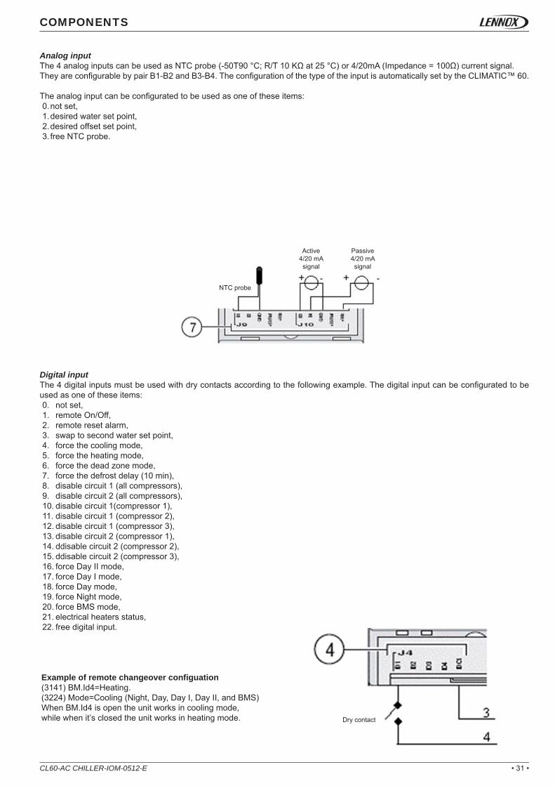
The expansion board BE60 is an additional board fi xed on DIN rail. The description of the various connectors is:1. Power supply of the board,2. Analog output 0/10V: not used,3. Network bus to the CLIMATIC™ 60 BM60,4. 4 digital inputs: dry contacts only,5. LED status of the network bus,6. Serial address dip-switch of the network bus,7. 4 analog inputs confi gurable by pair B1-B2 and B3-B4,8. 4 digital outputs: dry contacts only.
Power supplyThe expansion board BE60 is powered in 24Vac, +/-15%, 50-60Hz, Pmax=6W.
• 31 •CL60-AC CHILLER-IOM-0512-E
COMPONENTS
Analog inputThe 4 analog inputs can be used as NTC probe (-50T90 °C; R/T 10 KΩ at 25 °C) or 4/20mA (Impedance = 100Ω) current signal.They are confi gurable by pair B1-B2 and B3-B4. The confi guration of the type of the input is automatically set by the CLIMATIC™ 60.
The analog input can be confi gurated to be used as one of these items:0. not set,1. desired water set point,2. desired offset set point,3. free NTC probe.
Digital inputThe 4 digital inputs must be used with dry contacts according to the following example. The digital input can be confi gurated to be used as one of these items:0. not set,1. remote On/Off,2. remote reset alarm,3. swap to second water set point,4. force the cooling mode,5. force the heating mode,6. force the dead zone mode,7. force the defrost delay (10 min),8. disable circuit 1 (all compressors),9. disable circuit 2 (all compressors),10. disable circuit 1(compressor 1),11. disable circuit 1 (compressor 2),12. disable circuit 1 (compressor 3),13. disable circuit 2 (compressor 1),14. ddisable circuit 2 (compressor 2),15. ddisable circuit 2 (compressor 3),16. force Day II mode,17. force Day I mode,18. force Day mode,19. force Night mode,20. force BMS mode,21. electrical heaters status,22. free digital input.
Example of remote changeover confi guation(3141) BM.Id4=Heating.(3224) Mode=Cooling (Night, Day, Day I, Day II, and BMS)When BM.Id4 is open the unit works in cooling mode, while when it’s closed the unit works in heating mode.
Passive 4/20 mA signal
Active4/20 mA signal
NTC probe
Dry contact

• 32 •
(3131):
(3132):
(3133):
(3134):
(3135):
(3141):
(3142):
(3143):
(3144):
(3145):
(3146):
(3151):
(3152):
(3153):
(3154):
CL60-AC CHILLER-IOM-0512-E
COMPONENTS
Digital outputThe 4 digital outputs are dry contacts and the maximum commutable power is 2000VA, 250Vac.The digital output can be confi gurated to be used as one of these items:
0. not set,1. general alarm (alarm minor),2. general fault (alarm major),3. general alarm on circuit 1,4. general alarm on circuit 2,5. general alarm on condenser,6. general alarm on evaporator pump(s),7. fl ow evaporator alarm,8. unit enable,9. unit available (ready to start),10. unit running (one compressor ON),11. unit running 100% (all compressor(s) ON),12. unit operating in cooling mode,13. unit operating in heating mode,14. unit operating in dead zone mode,15. unit operating in zone 016. unit operating in zone 1,17. unit operating in zone 2,18. unit operating in zone 3,19. unit operating in zone 4,20. unit operating in zone 5,21. unit operating in zone 6,22. unit operating in mode Day II,23. unit operating in mode Day I,24. unit operating in mode Day,25. unit operating in mode Night,26. unit operating in mode BMS,27. output for additional electrical heater 1,28. output for additional electrical heater 2,29. output for additional electrical heater 3,30. output for additional electrical heater 4,31. Unit on Defrost operation32. free digital output.
SettingsThe different settings to confi gure the custom I/O are available in the menu:
setting for the digital output on the connector BM60-J14-NO7,
setting for the digital output on the connector BE60-J5-NO1,
setting for the digital output on the connector BE60-J6-NO2,
setting for the digital output on the connector BE60-J7-NO3,
setting for the digital output on the connector BE60-J8-NO4.
setting for the digital input on the connector BM60-J4-ID4,
setting for the digital input on the connector BM60-J4-ID7,
setting for the digital input on the connector BE60-J4-ID1,
setting for the digital input on the connector BE60-J4-ID2,
setting for the digital input on the connector BE60-J4-ID3,
setting for the digital input on the connector BE60-J4-ID4.
setting for the analog input on the connector BE60-J9-B1,
setting for the analog input on the connector BE60-J9-B2,
setting for the analog input on the connector BE60-J10-B3,
setting for the analog input on the connector BE60-J10-B4.
Dry contact
Note: in case of communication loss between BE60 and BM60, the expansion board inputs / outputs keeps the previous status before this communication loss.

• 33 •
(2111):
(2112):
(2113):
CL60-AC CHILLER-IOM-0512-E
COMPONENTS
ON / OFF CONTROL
FunctionThere are various ways to start up the unit: manually or automatically.
DescriptionThere are up to 4 ways to start / stop the unit with the CLIMATIC™ 60:• The unit can be turned ON or OFF manually by the terminals DC60 Advanced or DS60 in the menu (2111) or DC60 .• A remote contact can also be connected directly to the electrical box to switch the unit ON or OFF. The switch status is displayed
in the menu (2112).• The startup of the unit can be confi gured according to a scheduling in the menu (2113).• The BMS can write directly in the general ON/OFF to start / stop the unit.
Note: the unit is considered as “ON” if only all settings (2111), (2112), (2113) are set to ON.
SettingsThe different settings to start up are available in the menu:
General ON /OFF,
Remote ON /OFF,
Schedule ON /OFF.

• 34 •
(2121):
(2122):
(2123):
(2124):
(2125):
(2126):
CL60-AC CHILLER-IOM-0512-E
COMPONENTS
REAL TIME CLOCK
FunctionThe CLIMATIC™ 60 board includes a real time clock which permits a schedule programmation and alarm events recording.
DescriptionThe clock is updated by terminal DC60 Advanced or DC60 or DS60 or BMS. Moreover, the time change is automatically updated for winter (last Sunday of October at 3h00) and summer (last Sunday of March at 2h00). This functionality can be disabled in menu (2126).
To update the clock by BMS, a fl ag must be set to 1 before sending the new date.
Note: if the DS60 is connected, the clock can’t be updated by the DC60.
SettingsThe different settings to adjust the clock are available in the menu:
Clock hour,
Clock minute,
Clock day (of the month),
Clock month,
Clock year,
Automatic clock update.

• 35 •
BM60..B. Rx-/Tx- BM60..B. Rx-/Tx-
BM60..B. Rx+/Tx+ BM60..B. Rx+/Tx+
17% 17%17% 17%
CL60-AC CHILLER-IOM-0512-E
COMMUNICATION
MASTER / SLAVE
FunctionThe CLIMATIC™ 60 offers possibilities to connect up to 8 units to allow relationship between each unit in order to perform the system.
The pLAN bus is connected to CLIMATIC™ 60 on the J8 connector of board BM60. A star connection is not recommended. For an optimum operation it is advised to connect a maximum of two cables per unit.The cable length should not exceed 500 m and you must use a 2 pairs with general shield like LiYCY-P (0.34 mm²).
DescriptionThere are 2 different modes to manage the units (“Cascade” & “Backup”)
The cascade mode:The cascade mode is used to engage additional cooling / heating capacity in order to reach the water set point. This master/slave operating includes 2 modes:• Twin mode: the units work simultaneously in order to equalize the number of compressors stages to perform the capacity of the unit.
The control manages only the capacity increase. The stage(s) decrease is controlled individually by each unit. The power factor capacity power is also controlled individually on each unit according to its demand.In case of evaporator pumps management, all pumps are started.
Unit n°1 Unit n°7Unit n°2
Max: 500 m
Unit n°8
Unit n°1 Unit n°7Unit n°2 Unit n°8

• 36 •
….U1 → U2 → U3 → U4 →….….U4 → U1 → U2 → U3 →….….U3 → U4 → U1 → U2 →….….U2 → U4 → U3 → U1 →….
100%
0%
15%
0%
20%
0%
17%
17%
17%
0%
20%
20%
CL60-AC CHILLER-IOM-0512-E
COMMUNICATION
The backup modeUsed to help the system in case of alarm(s) on the unit running. The unit in standby will start only if one of the other unit(s) running is in alarm. In this case the unit in alarm will be stopped and replace by the one which was in standby.
The CLIMATIC™ 60 manages also the rotation between the declared units . In “Cascade” mode, that means that the fi rst unit to start will change every week. In “Rol.Backup” mode, the unit in “Backup” is swapped every week.
Example:In case of 4 units, the rotation is as follow:
• Chain mode: the units starts one after the other in serial sequence. In case of evaporator pump(s) in the unit, the pump(s) is engaged according to the demand of the system.
The selectd unit in standby is the one which has the higher critical(s) alarm(s). In case of disconnection of the slave(s) unit(s) (@pLAN = 2 → 8) from the master unit (@pLAN = 1) on the pLAN bus, the disconnected unit will operate alone.
Week Example Unit rotationWeek (n modulo 5) Week 1
Week (n+1 modulo 5) Week 2Week (n+2 modulo 5) Week 3Week (n+3 modulo 5) Week 4
Unit n°1
Unit n°1
Unit n°1
Unit n°7
Unit n°7
Unit n°7
Unit n°2
Unit n°2
Unit n°2
Unit n°8
Unit n°8
Unit n°8
ALAR
M

• 37 •CL60-AC CHILLER-IOM-0512-E
COMMUNICATION
DC60 DISPLAY
FunctionThe DC60 display is customized for the user to show a global operating overview of the unit and allow access to some settings. In case of remote display, the cable length should not exceed 30 m.
DescriptionThe DC60 terminal displays various status of the unit and offers the possibility to override the initial operating of the unit. Use the wheel button to display the data desired in the big area. The small area specifi es the type of the data displayed.
Set point “SET”:Specify the evaporator water set point calculated by CLIMATIC™ 60. The set point can be modifi ed directly by the DC60. Note that the selected value will automatically be overwritten by CLIMATIC™ 60 when the actual zone will change (Z0 → Z6) if a scheduling has been defi ned.
Unit number “UNIT”:Specify the Unit number.
Outlet temperature “OUT”:Specify the evaporator water outlet temperature.
Inlet temperature “IN”Specify the water evaporator inlet temperature.
Outside temperature “Air”Specify the outside air temperature.
Alarm code “AL-”Specify the active alarm(s) code(s).
Low pressure “LP-1”Specify the low pressure of circuit 1.
High pressure “HP-1”Specify the high pressure of circuit 1.
Low pressure “LP-2”Specify the low pressure of circuit 2.
High pressure “HP-2”Specify the high pressure of circuit 2.
Schedule zone 'Sche"Specify the actual schedule zone.
Changeover mode
Big area
Unit mode
Small area
Status area

• 38 • CL60-AC CHILLER-IOM-0512-E
COMMUNICATION
SettingsThe CLIMATIC™ 60 offers possibilities of override operations.
On/OffWhen the “power” button is pressed during few seconds, the unit is ordered to start or stop. When the unit is “OFF”, the clock is displayed.
Changeover modeThe changeover mode (cool / heat) can be modifi ed through the DC60 terminal by pressing the “mode” button.
When the “Auto” mode is selected, icon “Cool” or “Heat” or "no icon" is displayed to signal the current operating mode. Due to communication delay, after pressing the “mode” button it is advised to wait few seconds to refresh of the icon on the display. After the unit start-up,the "mode" button pressure is ignored during a few seconds.
Clock: Time setting:
• Press the “clock” button during few seconds. When the hour is blinking, turn the wheel button to select the desired hour and validate by pressing the wheel button. Once the hour is validated, repeat the procedure for the minute and the weekday.
Installation Note.The remote display DC60 must be installed in the fi eldbus and its connection must be in serial with the other Fielbus devices (star connection are not permitted).If the remote display DC60 is the furthest device on the Fieldbus from the unit, a 120Ω resistence must be connected between its + and – terminals (for further information, please refer to the unit electrical diagram)
Schedule zoneSpecify the schedule operating zone.
Day mode, Day I mode, Day II mode, Night mode, BMS mode
The DC60 terminal also displays the status of the main component of the unit in the status area. The icons can take different appearance according to the status of the component.
Defrost
Compressors
General alarm
Pump OFF (icons hidden)
Pump ON (icons visible)
Pump alarm (icons blinking)
Evaporator pump(s)
Heat → Cool → Auto

• 39 •
Display addresssetting ........: xx
I O Board address: xx
-LENNOX--LENNOX-Language��-English
CH 060 STD
Vers: 01.0Rev: 00.0Boot: 4.05
Language��-English
CH 060 STD
Vers: 01.0Rev: 00.0Boot: 4.05
1 112 123 134 145 156 167 178 18
CL60-AC CHILLER-IOM-0512-E
COMMUNICATION
"DC60 ADVANCED" DISPLAY OR "DS60 SERVICE" DISPLAY
Function• the "DC60 Advanced" is the display mounted on the NEOSYS™ units and available as an option for the ECOLEANTM.• the "DS60 Service" is a plug and play disply designed for maintenance and expert service people who want to access to advanced
functionalities.
DescriptionThe terminal address is automatically set by the CLIMATIC™ 60 when connected. The address can yet be assigned manually to establish the communication with the CLIMATIC™ 60. The procedure to confi gure the DC60 Advanced / DS60 is:• Press the buttons “↓”, “↑”, “←” keys at the same time during 5 seconds,• Use the “←” key to move the cursor on the address number,• Use the “↓”, “↑” keys to select the value “11 → 18” for the "DC60 Advanced" and 32 for the DS60 (or DS50) and confi rm with the
“←” key (the cursor go directly to the next data).
Display address
CLIMATIC™ BM60 address
UNIT NUMBER DC60 ADVANCED ADDRESS
• For a DC60 Advanced" select the adress according to the following table

• 40 •
P01: Adr Priv / sharedTrm1 31 PrTrm2 None --Trm3 None -- OK? No
-LENNOX-Language��-English
CH 060 STD
Vers: 01.0Rev: 00.0Boot: 4.05Bios: 5.09
||||||
Display addresschanged
Terminal confi gPress ENTERto continue
CL60-AC CHILLER-IOM-0512-E
COMMUNICATION
• Use the “↓”, “↑” keys to select the desired address of CLIMATIC™ 60. CLIMATIC™ 60 address must be at the address “1” except if there is several units linked. The next screen is displayed.
• Press the “←” key to go to the next step.• The following screen describes the used connection type. Set the display as a Private “Pr” terminal. The other terminals (Trm2 and
Trm3) are not used. So their addresses must be adjusted to “None”. Finally confi rm the modifi cations, swapp the text “No” to “Yes” and validate with the“←” key.
After a star up, the fi rst screen contains the main information about the CLIMATIC™ 60‘s software.
Private displayDisplay address
• If the address has been modifi ed, the next screen is displayed. Otherwise restart step 1.

• 41 •
(0000)1 Alarm2 User3 Expert
Unit: 01Zone: 0Mode: A
Wednesday01/09/1014:32:50
|||||||
|||
Alarm 0101>04/10.14h23 11402>22/09.11h23 . 11403>00/00.00h00 . 00004>00/00.00h00 . 00005>00/00.00h00 . 00006>00/00.00h00 . 00007>00/00.00h00 . 000
(0000)1 Alarm2 User
Unit: 01Zone: 0Mode: A
Wednesday01/09/1014:32:50
CL60-AC CHILLER-IOM-0512-E
COMMUNICATION
The DC60 Advanced / DS60 is organised in 3 menus:• (1000): alarms history,• (2000): user menus for maintenance people,• (3000): (Only for DS60) Expert menus for service people (restricted area).
To access to alarms history, press the “ALARM” key when you are in the main menu (0000). The CLIMATIC™ 60 saves up to the last 32 alarms. An active alarm is signaled by the symbol “Alarm” whereas an alarm inactive is symbolized by the “.”To reset the current active alarm(s) press the “ALARM” key.
Actual zone, mode
Actual clock
Number of active alarm(s)
Alarm codeAlarm number
Alarm status (Active)Alarm date
Alarm trip hour

• 42 •
(3230)01 Mode Jour II3 Outlet 13.3°C4 Setpoint 07.0°C4 Capacity 000.0%4 Air 1 22.0°C4 Air 2 30.0°C4 Water 1 07.0°C4 Water 2 07.0°C
|||||||
CL60-AC CHILLER-IOM-0512-E
COMMUNICATION
The “↓” and “↑” keys are used to move the cursor on the desired item. Then use the “←” key to enter in the selected submenu. To escape a menu use "ESC" the key.
The submenus contains 2 types of data: the read only data (like a temperature probe for example) and the read/write setpoints (like the cooling water setpoint for example). The data are identifi ed by a cursor symbol “>” whereas the setpoint are identify by a symbol “>>”.
Customizable setting for different mode
Actual set point
The menus are organised in arborescence tree with submenus as per the scheme hereunder. The actual menu is identifi ed by a 4 digit number between brackets displayed in the top left corner of the screen.The complete menu list is detailed in the appendix at the end of the document:• Description of each menu• Explanation of each menu code digit.• Type of information in the menu - Read (R), Write (W), Possibility to write in different schdule zone (Z)• Min / Factory / Max values
Menu (3000)
Menu (3100)
Menu (3110) Menu (3160)
Menu (3820)Menu (3810)
Menu (3800) Menu (3161) Menu (3169)
Menu (3821) Menu (3829)

• 43 •
(3230)01 Mode Jour II
Water 207.0�
� 20.0
� 07.0� 05.0� 06.0
>|||||>>
(3230)01 Mode Jour II3 Outlet 13.3°C4 Setpoint 07.0°C4 Capacity 000.0%4 Air 1 22.0°C4 Air 2 30.0°C4 Water 1 07.0°C4 Water 2 07.0°C
CL60-AC CHILLER-IOM-0512-E
COMMUNICATION
To modify a setting, move the cursor on the desired item and press the “←” key. A new screen displays information concerning this set point. To modify it, use the “↓” and “↑” keys and validate by pressing the “←” key. If the setting is customizable according to the schedule mode, press the “PRG” key to select different value for the Day, Day I, Day II & Night modes.
: to quickly increment or decrement the setting, hold the “↓” or “↑” keys during few time.
Cursor symbol for set point
User save value
Minimum value
Factory value
Maximum value
Cursor symbol for data

• 44 • CL60-AC CHILLER-IOM-0512-E
COMMUNICATION
The connection must be carried out by the following cable: length up to 1000 m: LiYCY-P (0.34 mm ²), 2 pairs with general shield.
The CLIMATIC™ 60 offers different possibilities of BMS protocol:• Modbus RTU,• Trend,• Bacnet,• Lon Works.
Modbus is a serial communications protocol published by Modicon in 1979, and has become a standard communications protocol in industry. It is now the most commonly available method to connect industrial electronic devices. Controllers communicate using a master–slave technic, in which only one device (master) can initiate transactions (called ‘queries’). The other devices (slaves) answer by supplying the requested data to the master, or by taking the action requested in the query.
Max = 1000 m
SERAIL CARDCND (+) (-)
Connect a 120Ω 1/4W end line resistor (only for
Modbus)
BMS
FunctionBMS (building management systems) are systems for the integrated management of all the technological functions of a building, including access control, safety, fi re détection, lighting, intelligent elevators, and air-conditioning. The resulting advantages of such solutions are simpler and more effi cient management of the building from a single control station, reduction in running costs, possibility of statistical analysis of all data, immediate identifi cation and response to faults and alarms. This amply justify the little extra cost of the air-conditioning unit BMS connectable. Today not only the quality and the reliability of the instruments are important, but also the degree of external connectivity they can offer.
DescriptionThe communication bus is connected on CLIMATIC™ 60’s serial card board on the BM60. A star connection is not allowed, for an optimum operation, it is advised to connect a maximum of two cables per unit. In case of RS485 bus, a resistance of 120Ω 1/4W can be connected on the last unit between the terminals + and -.

• 45 •
RS485 (EIA/ TIA - 485 Standard)
RTU (Remote Terminal Unit)
1200→19200 Bauds
8 bits
None
2 bit
(3826):
(3827):
(3828):
(3184):
CL60-AC CHILLER-IOM-0512-E
COMMUNICATION
LENNOX units implement Modbus slave protocol with the following settings:
SettingsThe different settings to confi gure the BMS are available in the menu:
«Watchdog» functionality with CLIMATIC 60.As the CLIMATIC 60 is passive on the bus, it cannot detect a communication failure with BMS; if any, the Roof-top would continue to operate with the last setting sent by the BMS before the failure whatever they were.
In order to avoid this scenario and tell regularly the CLIMATIC 60 that it is still connected to the BMS, the BMS system has to send regularly to the adress 01h a number above 0.On its side the CLIMATIC 60 is decreasing the adress 01H value of 5 units every 5 seconds. If the adress 01H reach 0, the climatic 60 consider the communication as lost and switch to stand alone mode.
Example, the BMS is sending the value 1000 to the adress 01h, after 200s if the BMS has not sent anything else, the value will reach 0, the CLIMATIC 60 will consider the communication as lost and the unit will regulate with its own parameters.
Modbus, BACnet, Trend, CarelPlease see the different corresponding tables in the appendix 1.
LonWorksPlease see the different corresponding tables in the appendix 2.
address of the unit (bus id)
choice of type of protocol
choice of speed of bus
watchdog counter
Serial Line
Transmission Mode
Baudrate
Data bits
Parity
Stop bits

• 46 •
1
2
7
8
9
10
21
22
23
24
25
26
27
28
34
40
41
42
43
44
45
46
47
48
49
50
54
5558
59
60
61
62
63
64
65
66
67
68
69
70
71
72
73
74
75
76
77
78
79
80
CL60-AC CHILLER-IOM-0512-E
COMMUNICATION
ALARMSCODE DESCRIPTION
Water Evaporator,Flow Switch,Cut Off
Water Condenser, Flow Switch, Cut Off
Buffer Tank,Water Level,Low
Buffer Tank,Water Level,High
Unit Power Supply
Unit,Electrical Heater,Electrical Failure
Water Evaporator,Water T°,Outlet Too High
Water Evaporator,Water T°,Outlet Too Low
Water Evaporator,Water T°,Inlet Too High
Water Evaporator,Water T°,Inlet Too Low
Water Condenser,Water T°,Outlet Too High
Water Condenser,Water T°,Outlet Too Low
Water Condenser,Water T°,Inlet Too High
Water Condenser,Water T°,Inlet Too Low
Electrical Box T°,Air T°,Too High
Pump Evaporator,Flow Switch,Cut Off
Pump Evaporator,Pump N° 1,Electrical Failure
Pump Evaporator,Pump N° 2,Electrical Failure
Pump Condenser,Pump N° 1,Electrical Failure
Pump Condenser,Pump N° 2,Electrical Failure
Pump Evaporator,In Pressure ,Faulty Sensor
Pump Evaporator,OUT Pressure ,Faulty Sensor
Pump Condenser,In Pressure ,Faulty Sensor
Pump Condenser,OUT Pressure ,Faulty Sensor
Pump Evaporator,Inverter,Electrical Failure
Pump Condenser,Inverter,Electrical Failure
Freecooling Fan,Inverter circuit breaker,Electrical Failure
Freecooling Fan,Inverter,Electrical FailureRecovery,Water Inlet T°,Faulty Probe
Recovery,Water Outlet T°,Faulty Probe
EEV driver, link failure
BM, Master, Failure
BM, Slave 2, Failure
BM, Slave 3, Failure
BM, Slave 4, Failure
BM, Slave 5, Failure
BM, Slave 6, Failure
BM, Slave 7, Failure
BM, Slave 8, Failure
Energy meter, link failure
BE.1, Communication Bus
BE.2, Communication Bus
BE.3, Communication Bus
Pump Evaporator,Inverter,Failure Link
Pump Condenser,Inverter,Failure Link
Circuit 1, Condenser Fan, Inverter, Communication Bus
Circuit 2, Condenser Fan, Inverter, Communication Bus
Circuit 1/2, Condenser Fan, Inverter, Communication Bus
Freecooling Fan,Inverter,Failure Link
DC Display,DC60 N°1,Failure Link
DC Display,DC60 N°2,Failure Link

• 47 •
81
83
85
89
90
97
98
102
103
104
105
106
107
108
110
111
112
113
114
115
116
117
118
121
122
123
124
127
128
129
131
132
141
142
143
144
145
146
147
148
149
202
203
204
210
211
212
213
214
215
216
CL60-AC CHILLER-IOM-0512-E
COMMUNICATION
CODE DESCRIPTIONWater Evaporator,Water Inlet T°,Faulty Probe
Outside Temperature, Faulty Probe
Water Evaporator,Water Outlet T°,Faulty Probe
Electrical Box T°,Air T°,Faulty Probe
Water Freecooling,Inlet T°,Faulty Probe
EVD board, EEPROM fainlure
Real Time Clock, Failure
Circuit 1, Condenser Fan, Failure
Circuit 1, Condenser Fan, Inverter circuit breaker, Failure
Circuit 1, Condenser Fan, Inverter Failure
Circuit 1/2, Condenser Fan Motor,Electrical Failure
Circuit 1/2, Condenser Fan, Inverter circuit breaker, Failure
Circuit 1/2, Condenser Fan, Inverter Failure
Unit,Power Factor CosPhi,Electrical Failure
Circuit 1, Refrigerant Leak, Detected
Circuit 1 Compressor 1,Discharge T°,Overheating
Circuit 1,Discharge T° Compressor 2,Overheating
Circuit 1,Discharge T° Compressor 3,Overheating
Circuit 1, Compressor, Electrical Failure
Circuit 1, High Pressure, Cut Off
Circuit 1, Reversing Valve, Blocked
Circuit 1, Low Pressure, Cut Off
Circuit 1,Water Evaporator,Risk Of Frosting
Circuit 1, High Superheat
Circuit 1, Low Superheat
Circuit 1, High Subcooling
Circuit 1, Low Subcooling
Circuit 1, MOP, Maximum Operating Pressure
Circuit 1, LOP, Low Operating Pressure
Circuit 1, High Condensing Temperature
Circuit 1,EEV Valve,Not Closed
Circuit 1, Expansion Valve, Motor
Circuit 1, High Pressure, Faulty Sensor
Circuit 1, Low Presure, Faulty Sensor
Circuit 1, Liquid Temperature, Faulty Probe
Circuit 1, Suction Temperature, Faulty Probe
Circuit 1,Discharge T° Compressor 1,Faulty Probe
Circuit 1,Discharge T° Compressor 2,Faulty Probe
Circuit 1,Discharge T° Compressor 3,Faulty Probe
Circuit 1,Water Condenser Inlet T°,Faulty Probe
Circuit 1,Water Condenser Outlet T°,Faulty Probe
Circuit 2, Condenser Fan, Failure
Circuit 2, Condenser Fan, Inverter circuit breaker, Failure
Circuit 2, Condenser Fan, Inverter Failure
Circuit 2, Leak Refrigerant, Detected
Circuit 2,Discharge T° Compressor 1, Overheating
Circuit 2,Discharge T° Compressor 2, Overheating
Circuit 2,Discharge T° Compressor 3, Overheating
Circuit 2, Compressor, Electrical Failure
Circuit 2, High Pressure, Cut Off
Circuit 2, Reversing Valve, Blocked

• 48 •
217
218
219
221
222
223
224
227
228
229
231
232
241
242
243
244
245
246
247
248
249
CL60-AC CHILLER-IOM-0512-E
COMMUNICATION
CODE DESCRIPTIONCircuit 2, Low Pressure, Cut Off
Circuit 2,Evaporator, Risk Of Frosting
Circuit 2,Low Condensing T°
Circuit 2, High Superheat
Circuit 2, Low Superheat
Circuit 2, High Subcooling
Circuit 2, Low Subcooling
Circuit 2, MOP, Maximum Operating Pressure
Circuit 2, LOP, Low Operating Pressure
Circuit 2, High Condensing Temperature
Circuit 2,EEV, Valve Not Closed
Circuit 2, Expansion Valve, Motor
Circuit 2, High Pressure, Faulty Sensor
Circuit 2, Low Presure, Faulty Sensor
Circuit 2, Liquid Temperature, Faulty Probe
Circuit 2, Suction Temperature, Faulty Probe
Circuit 2,Discharge T°, Compressor 1, Faulty Probe
Circuit 2,Discharge T°, Compressor 2, Faulty Probe
Circuit 2,Discharge T°, Compressor 3, Faulty Probe
Circuit 2,Water Condensing Inlet T°, Faulty Probe
Circuit 2,Water Condensing Outlet T°, Faulty Probe

• 49 •CL60-AC CHILLER-IOM-0512-E
COMMUNICATION
ALARM 001:WATER EVAPORATOR, FLOW SWITCH CUT OFF
ALARM 002:WATER CONDENSER, FLOW SWITCH CUT OFF
DescriptionThe fl ow switch has detected a low water fl ow rate in the evaporator heat exchanger for more than 5 seconds whereas the unit was enable.
ActionImmediate shut down of the complete unit.
ResetOnce the fl ow has been detected for 2 minutes, the alarm is automatically deleted. Up to 3 trips can occur during a day. The two fi rst trips don’t give the alarm alert except if the fault is not automatically reset within one hour. The 3rd one - or the previous one if they remains for more than an hour - activates the fault alert, is saved in the alarm history and must be manually reset. The alarm counter is reset every day at 6 am.
Possible cause(s)• Problem with the pump control wiring,• Problem with the fl ow switch wiring,• Dirty or clogged water fi lter,• Wrong setting of the fl ow switch.
Remedies• Check the pump(s) connections,• Check the fl ow switch connections,• Clean the water fi lter,• Check the fl ow switch settings.
DescriptionThe fl ow switch has detected a low water fl ow rate in the condenser heat exchanger for more than 5 seconds whereas the unit was enabling.
ActionImmediate shut down of the complete unit.
ResetOnce the fl ow has been detected for 2 minutes, the alarm is automatically deleted. Up to 3 trips can occur during a day. The two fi rst trips don’t give the alarm alert except if the fault is not automatically reset within one hour. The 3rd one - or the previous one if they remains for more than an hour - activates the fault alert, is saved in the alarm history and must be manually reset. The alarm counter is reset every day at 6 am.
Possible cause(s)• Problem with the pump control wiring,• Problem with the fl ow switch wiring,• Dirty or clogged water fi lter,• Wrong setting of the fl ow switch,
Remedies• Check the pump connections,• Check the fl ow switch connections,• Clean the water fi lter,• Check the fl ow switch settings.

• 50 • CL60-AC CHILLER-IOM-0512-E
COMMUNICATION
ALARM 021, 022, 023, 024: WATER EVAPORATOR, OUT OF RANGE
ALARM 025, 026, 027, 028:WATER CONDENSER, OUT OF RANGE
DescriptionThe water evaporator temperature (inlet or outlet) measured by the probe is outside of the permitted range for more than 5 mn. This operating range can vary according to the presence or not of glycol with the chilled water.• Alarm 021: the outlet water temperature is higher than the safety limit setting (3274) in heating mode,• Alarm 022: the outlet water temperature is lower than the safety limit setting (3271) in cooling mode,• Alarm 023: the inlet water temperature is higher than the safety limit setting (3272) in cooling mode,• Alarm 024: the inlet water temperature is lower than the safety limit setting (3273) in heating mode.
ActionImmediate shut down of the complete unit.
ResetThe alarm is automatically deleted once the temperature has reached the permitted operating range for 2 min. After a change over mode (cool / heat), these alarms are disabled during 15 min.
Possible cause(s)• Temperature probe failed• Problem with wiring of probe.
Remedies• Replace probe• Check the connections of the probe.
DescriptionThe water condenser temperature (Inlet or Outlet) measured by the probe is outside of the permitted range for more than 5mn.• Alarm 025: the outlet water temperature is higher than the safety limit setting (3574) in heating mode,• Alarm 026: the outlet water temperature is lower than the safety limit setting (3571) in cooling mode,• Alarm 027: the inlet water temperature is higher than the safety limit setting (3572) in cooling mode,• Alarm 028: the inlet water temperature is lower than the safety limit setting (3573) in heating mode.
ActionImmediate shut down of the complete unit. The alarm is signalling 5 min after if the condenser temperature is still out of range.
ResetThe alarm is automatically deleted once the temperature has reached the permitted operating range for 2 min. After a change over mode, these alarms are reset during 15 min.
Possible cause(s)• Problem with wiring of probe,• Temperature probe failed.
Remedies• Check the connections of the probe,• Replace probe.
• 51 •
58.0 62.0 65.0
CL60-AC CHILLER-IOM-0512-E
COMMUNICATION
ALARM 034:ELECTRICAL BOX, AIR TEMPERATURE TOO HIGH
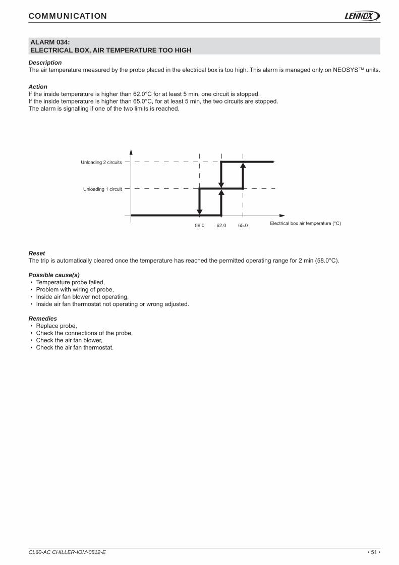
DescriptionThe air temperature measured by the probe placed in the electrical box is too high. This alarm is managed only on NEOSYS™ units.
ActionIf the inside temperature is higher than 62.0°C for at least 5 min, one circuit is stopped.If the inside temperature is higher than 65.0°C, for at least 5 min, the two circuits are stopped.The alarm is signalling if one of the two limits is reached.
ResetThe trip is automatically cleared once the temperature has reached the permitted operating range for 2 min (58.0°C).
Possible cause(s)• Temperature probe failed,• Problem with wiring of probe,• Inside air fan blower not operating,• Inside air fan thermostat not operating or wrong adjusted.
Remedies• Replace probe,• Check the connections of the probe,• Check the air fan blower,• Check the air fan thermostat.
Unloading 2 circuits
Electrical box air temperature (°C)
Unloading 1 circuit

• 52 • CL60-AC CHILLER-IOM-0512-E
ALARM 041, 042:PUMP EVAPORATOR, ELECTRICAL FAILURE
ALARM 043, 044:PUMP CONDENSER, ELECTRICAL FAILURE
DescriptionThe thermal magnetic circuit breaker protection of the evaporator pump 1 or 2 has tripped for 5 s, whereas the pump was in demand for at least 5 s.• Alarm 41: thermal magnetic circuit breaker protection of the pump 1,• Alarm 42: thermal magnetic circuit breaker protection of the pump 2.
ActionCase of single pump:• Immediate shut down of the pump and the unit. • The alarm is signalling.
Case of double pump:• Immediate shut down of the current pump and the compressor(s).• Time delay of 30 s,• Start the second pump if possible (refers to the “PUMP EVAPORATOR MANAGEMENT“ paragraph)• The alarm is signalling.
ResetThese alarms are manually reset.
Possible cause(s)• Problem with wiring connection,• Circuit breaker wrong adjusted.
Remedies• Check the pump(s) connections,• Adjust the circuit breaker.
DescriptionThe thermal magnetic circuit breaker protection of the condenser pump 1 or 2 has tripped for 5 s, whereas the pump was in demand for at least 5 s.• Alarm 43: thermal magnetic circuit breaker protection of the pump 1,• Alarm 44: thermal magnetic circuit breaker protection of the pump 2.
ActionCase of single pump:• Immediate shut down of the pump and the unit. • The alarm is signalling.
Case of double pump:• Immediate shut down of the current pump and the compressor(s).• Time delay of 30 s,• Start the second pump if possible (refers to the “PUMP CONDENSER MANAGEMENT“ paragraph)• The alarm is signalling.
ResetThese alarms are manually reset.
Possible cause(s)• Problem with wiring connection,• Circuit breaker wrong adjusted.
Remedies• Check the pump(s) connections,• Adjust the circuit breaker.
COMMUNICATION

• 53 •CL60-AC CHILLER-IOM-0512-E
COMMUNICATION
ALARM 045, 046:PUMP EVAPORATOR, FAULTY PRESSURE SENSOR
ALARM 047, 048: PUMP CONDENSER, FAULTY PRESSURE SENSOR
DescriptionThe evaporator water pressure (in or out) measured by the sensor is outside of the permitted range. This alarm is managed only if the “evaporator variable fl ow” option is selected.• Alarm 45: water evaporator pressure sensor IN faulty,• Alarm 46: water evaporator pressure sensor OUT faulty.
Action• Immediate shut down of the pump and the unit. • The alarm is signalling.
ResetOnce the CLIMATIC™ 60 has read correct pressure values for 2 minutes, the alarm is automatically deleted. Up to 3 trips can occur during a day. The two fi rst trips don’t give the alarm alert except if the fault is not automatically reset within one hour. The 3rd one - or the previous one if they remains for more than an hour - activates the fault alert, is saved in the alarm history and must be manually reset. The alarm counter is reset every day at 6 am.
Possible cause(s)• Problem with wiring connection (sensor in short circuit or disconnected),• Sensor damaged.
Remedies• Check the wiring connections,• Replace the sensor.
DescriptionThe water pressure of the condenser pump (in or out) measured by the sensor is outside of the permitted range. This alarm is managed only when the condenser variable fl ow option is selected.• Alarm 47: water condenser pressure sensor IN faulty,• Alarm 48: water condenser pressure sensor OUT faulty.
Action• Immediate shut down of the pump and the unit. • The alarm is signalling.
ResetOnce the CLIMATIC™ 60 has read correct pressure values for 2 minutes, the alarm is automatically deleted. Up to 3 trips can occur during a day. The two fi rst trips don’t give the alarm alert except if the fault is not automatically reset within one hour. The 3rd one - or the previous one if they remains for more than an hour - activates the fault alert, is saved in the alarm history and must be manually reset. The alarm counter is reset every day at 6 am.
Possible cause(s)• Problem with wiring connection (sensor in short circuit or disconnected),• Sensor damaged.
Remedies• Check the wiring connections,• Replace the sensor.

• 54 • CL60-AC CHILLER-IOM-0512-E
COMMUNICATION
ALARM 061, 062, 063, 064, 065, 066, 067, 068:CLIMATIC BOARD LINK, FAILURE
ALARM 070:REAL TIME CLOCK BOARD, FAILURE
DescriptionThe link between the master / slave CLIMATIC™ 60 boards is faulty.• Alarm 61: master CLIMATIC™ 60 n°1 board disconnected,• Alarm 62 → 68: slave CLIMATIC™ 60 board n°2 → 8 disconnected.
Action• Swap immediately the unit in stand alone mode. • The alarm is signalling.
ResetOnce the communication is re-established for 30 s,the alarm is automatically deleted. Up to 3 trips can occur during a day. The two fi rst trips don’t give the alarm alert except if the fault is not automatically reset within one hour. The 3rd one - or the previous one if they remains for more than an hour - activates the fault alert, is saved in the alarm history and must be manually reset. The alarm counter is reset every day at 6 am.
Possible cause(s)• Problem with wiring connection,• CLIMATIC™ 60 board power off,• CLIMATIC™ 60 board damaged.
Remedies• Check the wiring connections,• Check the power of CLIMATIC™ 60 board,• Replace the CLIMATIC™ 60 board.
DescriptionThe real time clock board of the CLIMATIC™ 60 doesn’t work. The battery if out of order or wrongly placed.
ActionThe alarm is signalling.
ResetThe alarm is manually reset.
Possible cause(s)• Battery level too low,• CLIMATIC™ 60 board damaged.
Remedies• Replace the battery (do not dispose of the product in a municipal waste; it
must be disposed of through specialist waste disposal centres), • Replace the CLIMATIC™ 60 board.

• 55 •CL60-AC CHILLER-IOM-0512-E
COMMUNICATION
ALARM 071, 072:EXPANSION BOARD LINK, FAILURE
ALARM 073, 074, 075, 076, 077, 078:INVERTER LINK, FAILURE
DescriptionThe link between the expansion board(s) 1 or 2 and the CLIMATIC™ 60 is disconnected.• Alarm 71: the expansion board N°1 is disconnected from the CLIMATIC™ 60,• Alarm 72: the expansion board N°2 is disconnected from the CLIMATIC™ 60.
Action• Immediate shut down of the unit. • The alarm is signalling.
ResetOnce the communication is re-established for 30 s, the alarm is automatically deleted. Up to 6 trips can occur during a day. The fi ve fi rst trips don’t give the alarm alert except if the fault is not automatically reset within one hour. The 6th one - or the previous one if they remains for more than an hour - activates the fault alert, is saved in the alarm history and must be manually reset. The alarm counter is reset every day at 6 am.
Possible cause(s)• Problem with wiring connection,• Wrong expansion board address,• Expansion board damaged.
Remedies• Check the wiring connections,• Check the expansion board address (refer to the “FREE INPUT / OUTPUT” paragraph),• Replace the expansion board.
DescriptionThe link between the inverter and the CLIMATIC™ 60 has been disconnected for 5 s.• Alarm 073: the evaporator pump inverter is disconnected from the CLIMATIC™ 60,• Alarm 074: the condenser pump inverter is disconnected from the CLIMATIC™ 60,• Alarm 075: the condenser fan inverter of circuit 1 is disconnected from the CLIMATIC™ 60,• Alarm 076: the condenser fan inverter of circuit 2 is disconnected from the CLIMATIC™ 60,• Alarm 077: the condenser fan inverter of circuit 1/2 is disconnected from the CLIMATIC™ 60,• Alarm 078: the condenser fan inverter of the freecooling is disconnected from the CLIMATIC™ 60.
Action• Alarm 073: immediate shut down of the complete unit. The alarm is signalling,• Alarm 074: immediate shut down of the complete unit. The alarm is signalling,• Alarm 075: immediate shut down of circuit 1. The alarm is signalling,• Alarm 076: immediate shut down of ircuit 2. The alarm is signalling,• Alarm 077: doesn’t stop circuit 1 or 2. The alarm is signalling,• Alarm 078: doesn’t stop the unit. The alarm is signalling.
ResetOnce the communication is re-established for 30 s, the alarm is automatically deleted. Up to 6 trips can occur during a day. The fi ve fi rst trips don’t give the alarm alert except if the fault is not automatically reset within one hour. The 6th one - or the previous one if they remains for more than an hour - activates the fault alert, is saved in the alarm history and must be manually reset. The alarm counter is reset every day at 6 am.
Possible cause(s)• Problem with wiring connection,• Wrong inverter address,• Inverter damaged.
Remedies• Check the wiring connections,• Check the inverter address,• Replace the inverter.

• 56 • CL60-AC CHILLER-IOM-0512-E
COMMUNICATION
ALARM 081, 083, 085, 089, 090, 141, 142, 143, 144, 145, 146, 148, 149, 241, 242, 243, 244, 245, 246, 248, 249:PROBE & SENSOR, FAULTY
DescriptionThe temperature probe or pressure sensor measured by the CLIMATIC™ 60 or other expansion boards is incorrect. The device may be disconnected or in short circuit for 5 s.• Alarm 081: the inlet water evaporator temperature probe value is incorrect,• Alarm 083: the outside air temperature probe value is incorrect,• Alarm 085: the outlet water evaporator temperature probe value is incorrect,• Alarm 089: the inside electrical box air temperature probe value is incorrect,• Alarm 090: the inlet freecooling water temperature probe value is incorrect,• Alarm 141: the high pressure sensor value on circuit 1 is incorrect,• Alarm 142: the low pressure sensor value on circuit 1 is incorrect,• Alarm 143: the liquid temperature probe value on circuit 1 is incorrect,• Alarm 144: the suction temperature probe value on circuit 1 is incorrect,• Alarm 145: the discharge temperature probe value on circuit 1 – compressor 1 is incorrect,• Alarm 146: the discharge temperature probe value on circuit 1 – compressor 2 is incorrect,• Alarm 148: the inlet water condenser temperature probe value on circuit 1 is incorrect,• Alarm 149: the outlet water condenser temperature probe value on circuit 1 is incorrect,• Alarm 241: the high pressure sensor value on circuit 2 is incorrect,• Alarm 242: the low pressure sensor value on circuit 2 is incorrect,• Alarm 243: the liquid temperature probe value on circuit 2 is incorrect,• Alarm 244: the suction temperature probe value on circuit 2 is incorrect,• Alarm 245: the discharge temperature probe value on circuit 2 – compressor 1 is incorrect,• Alarm 246: the discharge temperature probe value on circuit 2 – compressor 2 is incorrect,• Alarm 248: the inlet water condenser temperature probe value on circuit 2 is incorrect,• Alarm 249: the outlet water condenser temperature probe value on circuit 2 is incorrect.
Action• Alarm 081: immediate shut down of the complete unit. The alarm is signalling,• Alarm 083: immediate shut down of the complete unit. The alarm is signalling,• Alarm 085: immediate shut down of the complete unit. The alarm is signalling,• Alarm 089: doesn’t stop the unit. The alarm is signalling,• Alarm 090: doesn’t stop the unit. The alarm is signalling.• Alarm 141: immediate shut down of circuit 1. The alarm is signalling,• Alarm 142: immediate shut down of circuit 1. The alarm is signalling,• Alarm 143: immediate shut down of circuit 1. The alarm is signalling,• Alarm 144: immediate shut down of circuit 1. The alarm is signalling,• Alarm 145: immediate shut down of circuit 1. The alarm is signalling,• Alarm 146: immediate shut down of circuit 1. The alarm is signalling,• Alarm 148: immediate shut down of circuits 1 and 2, only if there is one condenser for both circuits,• Alarm 149: immediate shut down of circuits 1 and 2, only if there is one condenser for both circuits,• Alarm 241: immediate shut down of circuit 2. The alarm is signalling,• Alarm 242: immediate shut down of circuit 2. The alarm is signalling,• Alarm 243: immediate shut down of circuit 2. The alarm is signalling,• Alarm 244: immediate shut down of circuit 2. The alarm is signalling,• Alarm 245: immediate shut down of circuit 2. The alarm is signalling,• Alarm 246: immediate shut down of circuit 2. The alarm is signalling,• Alarm 248: immediate shut down of circuit 2. The alarm is signalling,• Alarm 249: immediate shut down of circuit 2. The alarm is signalling,
ResetOnce the data read is coherent for 2 minutes, the alarm is automatically deleted. Up to 3 trips can occur during a day. The two fi rst trips don’t give the alarm alert except if the fault is not automatically reset within one hour. The 3rd one - or the previous one if they remains for more than an hour - activates the fault alert, is saved in the alarm history and must be manually reset. The alarm counter is reset every day at 6 am.
Possible cause(s)• Problem with wiring connection,• Probe or sensor damaged.
Remedies• Check the wiring connections,• Replace the probe or sensor.

• 57 •CL60-AC CHILLER-IOM-0512-E
COMMUNICATION
ALARM 102, 105, 202:CONDENSER FAN, ELECTRICAL FAILURE
DescriptionThe thermal motor protection of the condenser fan has detected an over temperature for 5 s, while the fan motor was in demand for at least 5 s.• Alarm 102: thermal motor protection of the condenser fan on circuit 1,• Alarm 105: thermal motor protection of the condenser fan on circuit 1/2,• Alarm 202: thermal motor protection of the condenser fan on circuit 2.
Action• Alarm 102: immediate shut down of the circuit 1. The alarm is signalling,• Alarm 104: immediate shut down of the common fans of the circuits 1 & 2. The two circuits still running with the rest of the fans
available. The alarm is signalling,• Alarm 202: immediate shut down of the circuit 2. The alarm is signalling.
ResetOnce the data read is coherent for 2 minutes, the alarm is automatically deleted. Up to 3 trips can occur during a day. The two fi rst trips don’t give the alarm alert except if the fault is not automatically reset within one hour. The 3rd one - or the previous one if they remains for more than an hour - activates the fault alert, is saved in the alarm history and must be manually reset. The alarm counter is reset every day at 6 am.
Possible cause(s)• Wrong air fl ow operating,• Problem with wiring connection,• Fan motor damaged.
Remedies• Check the air system,• Check the connection,• Replace the fan motor.

• 58 • CL60-AC CHILLER-IOM-0512-E
COMMUNICATION
ALARM 108:POWER FACTOR CORRECTION, ELECTRICAL FAILURE
ALARM 049, 050, 054, 055, 103, 104, 106, 107, 203, 204:PUMP OR FAN INVERTER, FAILURE
DescriptionThe thermal magnetic circuit breaker protection of the capacitors (cos phi) has tripped for 5 s.
ActionThe alarm is signalling.
ResetThe alarm is manually reset.
Possible cause(s)• Problem with wiring connection,• Circuit breaker wrongly adjusted.
Remedies• Check the capacitor connection,• Adjust the circuit breaker.
DescriptionThe CLIMATIC™ 60 has detected an alarm on the pump or the fan inverter or on the inverter circuit breaker.• Alarm 049: inverter failure of the evaporator pump,• Alarm 050: inverter failure of the condenser pump,• Alarm 054: inverter circuit breaker failure of the freecooling fan,• Alarm 055: inverter failure of the freecooling fan,• Alarm 103: inverter circuit breaker failure of the condenser fan on circuit 1,• Alarm 104: inverter failure of the condenser fan on circuit 1,• Alarm 106: inverter circuit breaker failure of the condenser fan on circuit 1/2,• Alarm 107: inverter failure of the condenser fan on circuit 1/2,• Alarm 203: inverter circuit breaker failure of the condenser fan on circuit 2.• Alarm 204: inverter failure of the condenser fan on circuit 2.
Action• Alarm 049: immediate shut down of the complete unit. The alarm is signalling,• Alarm 050: immediate shut down of the complete unit. The alarm is signalling,• Alarm 054, 055: immediate shut down of the freecooling fan. The alarm is signalling,• Alarm 103, 104: immediate shut down of circuit 1. The alarm is signalling,• Alarm 106, 107: immediate shut down of circuits 1/2. The alarm is signalling,• Alarm 203, 204: immediate shut down of circuit 2. The alarm is signalling.
ResetThe alarm is manually reset.
Possible cause(s)• Problem with wiring connection,• Pump or fan damaged,• Inverter damaged.
Remedies• Check the inverter connection,• Replace the pump or fan,• Replace the inverter.

• 59 •CL60-AC CHILLER-IOM-0512-E
COMMUNICATION
ALARM 111, 112, 211, 212:DISCHARGE TEMPERATURE COMPRESSOR, OVERHEATING
DescriptionThe CLIMATIC™ 60 has detected an overheating discharge temperature on the compressor.• Alarm 111: overheating discharge temperature on circuit 1 – compressor 1,• Alarm 112: overheating discharge temperature on circuit 1 – compressor 2,• Alarm 211: overheating discharge temperature on circuit 2 – compressor 1,• Alarm 212: overheating discharge temperature on circuit 2 – compressor 2.
ActionImmediate shut down of the compressor. The alarm is signalling.
ResetOnce the discharge temperature has reached a permitted operating range for 2 minutes, the alarm is automatically deleted. Up to 3 trips can occur during a day. The two fi rst trips don’t give the alarm alert except if the fault is not automatically reset within one hour. The 3rd one - or the previous one if they remains for more than an hour - activates the fault alert, is saved in the alarm history and must be manually reset. The alarm counter is reset every day at 6 am.
Possible cause(s)• Problem of refrigerant capacity,• Compressor damage.
Remedies• Check the frigorifi c operating,• Replace the compressor.
ALARM 114, 214:COMPRESSOR, ELECTRICAL FAILURE
DescriptionThe thermal magnetic circuit breaker protection or the thermal motor protection of the compressor has tripped.• Alarm 114: thermal magnetic circuit breaker open on circuit 1,• Alarm 214: thermal magnetic circuit breaker open on circuit 2.
ActionImmediate shut down of the complete circuit. The alarm is signalling.
ResetThe alarm is manually reset.
Possible cause(s)• Problem with wiring connection,• Circuit breaker wrongly adjusted,• Compressor damage.
Remedies• Check the wiring connection,• Adjust the circuit breaker,• Replace the compressor.

• 60 • CL60-AC CHILLER-IOM-0512-E
COMMUNICATION
ALARM 115, 215:HIGH PRESSURE, CUT OFF
DescriptionThe high pressure switch has trip for 5 s while a compressor was running for 10 s.• Alarm 115: high pressure cut off on circuit 1,• Alarm 215: high pressure cut off on circuit 2.
ActionImmediate shut down of the complete circuit. The alarm is signalling.
ResetOnce the circuit has been stopped for 30 minutes, the alarm is automatically deleted. Up to 3 trips can occur during a day. The two fi rst trips don’t give the alarm alert except if the fault is not automatically reset within one hour. The 3rd one - or the previous one if they remains for more than an hour - activates the fault alert, is saved in the alarm history and must be manually reset. The alarm counter is reset every day at 6 am.
Possible cause(s)• Problem with wiring connection,• Coil condenser dirty,• Fan condenser not operating.
Remedies• Check the wiring connection,• Clean the coil condenser,• Check the fan operating.
ALARM 116, 216:REVERSING VALVE, BLOCKED
DescriptionThe CLIMATIC™ 60 hasn’t measured a difference of pressure of 1 bars for 5 s, while a compressor was running for 60 s.• Alarm 116: reversing valve blocked on circuit 1,• Alarm 216: reversing valve blocked on circuit 2.
ActionImmediate shut down of the complete circuit. The alarm is signalling.
ResetOnce the circuit has been stopped for 2 minutes, the alarm is automatically deleted. Up to 3 trips can occur during a day. The two fi rst trips don’t give the alarm alert except if the fault is not automatically reset within one hour. The 3rd one - or the previous one if they remains for more than an hour - activates the fault alert, is saved in the alarm history and must be manually reset. The alarm counter is reset every day at 6 am.
Possible cause(s)• Problem with wiring connection,• Problem of reversing valve.• Issue with the compressor(s) ASTP protection. the compresseur does not compress anymore
Remedies• Check the wiring connection,• Replace the reversing valve• Check the good compressor operation.

• 61 •CL60-AC CHILLER-IOM-0512-E
COMMUNICATION
ALARM 117, 217:LOW PRESSURE, CUT OFF
DescriptionThe suction temperature calculated by the LP pressure sensor is lower than the permitted threshold. The temperature has reached -27.0°C (1 minute delayed in heating mode) while a compressor was running for 30 s. The alarm is disable during 1 minute if the defrost procedure is running. In any case if the LP temperature reaches -37.0°C, the circuit is stopped immediately without time delay.• Alarm 117: suction temperature too low on circuit 1,• Alarm 217: suction temperature too low on circuit 2.
ActionImmediate shut down of the complete circuit. The alarm is signalling.
ResetOnce the circuit has been stopped for 2 minutes, the alarm is automatically deleted. Up to 3 trips can occur during a day. The two fi rst trips don’t give the alarm alert except if the fault is not automatically reset within one hour. The 3rd one - or the previous one if they remains for more than an hour - activates the fault alert, is saved in the alarm history and must be manually reset. The alarm counter is reset every day at 6 am.
Possible cause(s)• Problem of refrigerant capacity.• Problem with the TXV
Remedies• Check the frigorifi c operating• Replace the TXV.
ALARM 118, 218:WATER EVAPORATOR, RISK OF FROSTING
DescriptionThe suction pressure measured by the LP sensor is too low and may pose a risk for the water evaporator. These alarms are disabled if the unit has electronic expansion valve (EEV) or if the glycol rate is greater than 45%. The LP pressure has reached the limit specifi ed in the setting (3441) for 2 minutes while a compressor was running for at least 2 minutes. This alarm is disabled during 1 minute when a compressor start or stop or during the defrost procedure.• Alarm 118: risk of frosting the water evaporator by circuit 1,• Alarm 218: risk of frosting the water evaporator by circuit 2.
ActionImmediate shut down of the complete circuit. The alarm is signalling.
ResetOnce the suction pressure is higher than the setting (3441) for 2 minutes, the alarm is automatically deleted. Up to 3 trips can occur during a day. The two fi rst trips don’t give the alarm alert except if the fault is not automatically reset within one hour. The 3rd one - or the previous one if they remains for more than an hour - activates the fault alert, is saved in the alarm history and must be manually reset. The alarm counter is reset every day at 6 am.
Possible cause(s)• Problem of refrigerant capacity• Problem with the expansion valve.
Remedies• Check the frigorifi c operating,• Replace the expansion valve.

• 62 • CL60-AC CHILLER-IOM-0512-E
COMMUNICATION
ALARM 121, 122, 221, 222:EVAPORATOR, TEMPERATURE SUPERHEAT OUT OF RANGE
DescriptionThe CLIMATIC™ 60 has detected anormal superheating temperature on the circuit.• Alarm 121: superheat temperature too high on circuit 1,• Alarm 122: superheat temperature too low on circuit 1,• Alarm 221: superheat temperature too high on circuit 2,• Alarm 222: superheat temperature too low on tcircuit 2.
ActionThe circuit is still running. The alarm is signalling only if a DS60 is connected.
ResetThe alarm is automatically reset.
Possible cause(s)• Problem of refrigerant capacity• Problem with the expansion valve.
Remedies• Check the frigorifi c operating,• Replace the expansion valve.
ALARM 123, 124, 223, 224:CONDENSER, TEMPERATURE SUBCOOLING OUT OF RANGE
DescriptionThe CLIMATIC™ 60 has detected anormal subcooling temperature on the circuit.• Alarm 123: subcooling temperature too high on circuit 1,• Alarm 124: subcooling temperature too low on circuit 1,• Alarm 223: subcooling temperature too high on circuit 2,• Alarm 224: subcooling temperature too low on circuit 2.
ActionThe circuit is still running. The alarm is signalling.
ResetThe alarm is manually reset.
Possible cause(s)• Problem of refrigerant capacity• Problem with the expansion valve.
Remedies• Check the frigorifi c operating,• Replace the expansion valve.

• 63 •CL60-AC CHILLER-IOM-0512-E
COMMUNICATION
ALARM 127, 227, 327:MAXIMUM OPERATING PRESSURE (MOP), FAULTY
ALARM 128, 228, 328:LOW OPERATING PRESSURE (LOP), FAULTY
DescriptionThe suction pressure measured by the CLIMATIC™ 60 is outside a permitted range.• Alarm n27: Max operating pressure on circuit n,• Alarm n28: Low operating pressure on circuit n,
ActionThese alarms are only reported: it had no effect on compressors.
ResetThe alarm is automatically deleted if the pressure is correct. This trip is saved in the alarm history only if the DS60 is connected or if 999 faults were activated during one day.The daily counter is automatically reset every day at 11 am. The 999th trip is locked and must be manually reset.
Possible cause(s)• Problem of refrigerant capacity
Remedies• Check the frigorifi c system operation
ALARM 129, 229: CONDENSING TEMPERATURE, TOO HIGH
DescriptionThe condensing temperature measured by the CLIMATIC™ 60 is too high.• Alarm 129: high condensing temperature on circuit 1,• Alarm 229: high condensing temperature on circuit 2.
ActionImmediate shut down of one of the compressor on the circuit (the small one in uneven circuit, or the one which has the higher counter time for even circuit). The alarm is signalling.
ResetOnce the condensing temperature has been enough decrease for 2 minutes, the alarm is automatically reset.
Possible cause(s)• Problem with wiring connection,• Coil condenser dirty,• Fan condenser not operating,• Outside air temperature too high.
Remedies• Check the wiring connection,• Clean the coil condenser,• Check the fan operating.

• 64 • CL60-AC CHILLER-IOM-0512-E

• 65 •
66
71
73
CLIMATIC™ 60
CL60-AC CHILLER-IOM-0512-E
APPENDIXRef : CL60-AC CHILLER_Appendix-IOM-0512-E
TABLE OF CONTENTS
BMSAPPENDIX 1Modbus, BACnet, Trend, CarelAPPENDIX 2Lonworks
DS60 LIST
AIR COOLED CHILLER

APPENDIX 1ModBus, BACnet, Trend, Carel PROTOCOLS
@ADDRESS FORMAT R/W DESCRIPTION MIN STD MAX01 Integer R/W bms, watchdog counter 0 0 32000
2 Integer R/W unit, general on/off, start & stop, set point 0 22,0 1
3 Integer R/W unit, reset alarms, set point 0 19,0 1
4 Integer R/W Setpoint update clock 0 20,0 1
5 Integer R/W clock, hour setting 0 35,0 23
6 Integer R/W clock, minute setting 0 15,0 60
7 Integer R/W clock, day setting 1 0,0 31
8 Integer R/W clock, month setting 1 100,0 12
9 Integer R/W clock, year setting 1 0,0 99
10 Integer R/W power meter, value for reset memory 0 100,0 1
11 Integer R/W Setpoint override evaporator water setpoint 0 0,0 20
12 Integer R/W control, bms day, set point of cooling mode 7 ~ 20
13 Integer R/W control, bms day, set point of heating mode 20 ~ 50
14 Integer R/W Setpoint override dead zone mode 0 0 1
15 Integer R/W Setpoint override mode BMS 0 ~ 1
16 Integer R/W Setpoint override mode Night 0 ~ 1
17 Integer R/W Setpoint disable compressor(s) circuit 1 0 ~ 1
18 Integer R/W Setpoint disable circuit 1 compressor 1 0 ~ 1
19 Integer R/W Setpoint disable circuit 1 compressor 2 0 ~ 1
20 Integer R/W Setpoint disable circuit 1 compressor 3 0 -99,9 1
21 Integer R/W Setpoint disable compressor(s) circuit 2 0 0,0 1
22 Integer R/W Setpoint disable circuit 2 compressor 1 0 -99,9 1
23 Integer R/W Setpoint disable circuit 2 compressor 2 0 0,0 1
24 Integer R/W Setpoint disable circuit 2 compressor 3 0 0 1
25 Integer R/W remote control, activation of bm j14 no7 0 0,0 1
26 Integer R/W remote control, activation of be-1 j5 no1 0 ~ 1
27 Integer R/W remote control, activation of be-1 j6 no2 0 ~ 1
28 Integer R/W remote control, activation of be-1 j7 no3 0 ~ 1
29 Integer R/W remote control, activation of be-1 j8 no4 0 ~ 1
30 Integer R/W [BMS] Emulation water evaporator T°inlet -40 ~ 80
31 Integer R/W [BMS] Emulation water evaporator T°outlet -40 ~ 80
32 Integer R/W [BMS] Emulation outside air T° -40 ~ 80
33 Integer R/W [BMS] Setpoint water evaporator cool 7 ~ 20
34 Integer R/W [BMS] Setpoint water evaporator heat 20 20,5 50
35 Integer R/W [BMS] Setpoint changover cool / heat (1=Cooling; 2=Heating; 3=Auto; 4=DeadZone) 1 ~ 4
36 Integer R/W [D] Setpoint changover cool / heat 1 ~ 4
37 Integer R/W [D] Cooling dynamic setpoint outside air T°1 -10 ~ 30
38 Integer R/W [D] Cooling dynamic setpoint outside air T°2 -10 ~ 30
39 Integer R/W [D] Cooling dynamic setpoint water evaporator T°1 7 ~ 20
40 Integer R/W [D] Cooling dynamic setpoint water evaporator T°2 7 ~ 20
41 Integer R/W [D] Heating dynamic setpoint outside air T°1 -10 ~ 30
42 Integer R/W [D] Heating dynamic setpoint outside air T°2 -10 ~ 30
43 Integer R/W [D] Heating dynamic setpoint water evaporator T°1 20 ~ 50
44 Integer R/W [D] Heating dynamic setpoint water evaporator T°2 20 ~ 50
45 Integer R/W [BMS] Setpoint enable compressor(s) circuit 1 0 ~ 8
46 Integer R/W [BMS] Setpoint enable compressor(s) circuit 2 0 ~ 8
47 Integer R/W [D] Setpoint enable compressor(s) circuit 1 0 ~ 8
48 Integer R/W [D] Setpoint enable compressor(s) circuit 2 0 ~ 8
49 Integer R/W [BMS] Setpoint water evaporator pump(s) mode 0 ~ 7
50 Integer R/W [D] Setpoint water evaporator pump(s) mode 0 ~ 7
51 Integer R/W [BMS] Setpoint water condenser pump(s) mode 0 ~ 7
52 Integer R/W [D] Setpoint water condenser pump(s) mode 0 ~ 7
53 Integer R/W [BMS] Setpoint fan condenser mode 0 ~ 2
54 Integer R/W [D] Setpoint fan condenser mode 0 ~ 2
55 Integer R/W [BMS] Setpoint accoustic noise level *** ~ ***
56 Integer R/W [D] Setpoint accoustic noise level *** ~ ***
100 Integer R Rolling alarm code 0 1 32767
CL60-AC CHILLER-IOM-0512-E . 66 .

APPENDIX 1ModBus, BACnet, Trend, Carel PROTOCOLS
@ADDRESS FORMAT R/W DESCRIPTION MIN STD MAX
101 Integer R
Alarm code 01Bit00: Alarm code 61,Bit01: Alarm code 62,Bit02: Alarm code 63,Bit03: Alarm code 64,Bit04: Alarm code 65,Bit05: Alarm code 66,Bit06: Alarm code 67,Bit07: Alarm code 68,Bit08: Alarm code 70,Bit09: Alarm code 71,Bit10: Alarm code 72,Bit11: Alarm code 79,Bit12: Alarm code 80,Bit13: Alarm code 60,Bit14: Alarm code 69,Bit15: Not used.
0 0 32767
102 Integer R
Alarm code 02Bit00: Alarm code 98,Bit01: Alarm code 97,Bit02: Alarm code 89,Bit03: Alarm code 34,Bit04: Alarm code 83,Bit05: Not used,Bit06: Not used,Bit07: Not used,Bit08: Not used,Bit09: Not used,Bit10: Not used,Bit11: Not used,Bit12: Not used,Bit13: Not used,Bit14: Not used,Bit15: Not used.
0 0 32767
103 Integer R
Alarm code 03Bit00: Alarm code 81,Bit01: Alarm code 85,Bit02: Alarm code 23,Bit03: Alarm code 24,Bit04: Alarm code 21,Bit05: Alarm code 22,Bit06: Alarm code 40,Bit07: Alarm code 40,Bit08: Alarm code 1,Bit09: Not used,Bit10: Not used,Bit11: Not used,Bit12: Not used,Bit13: Not used,Bit14: Not used,Bit15: Not used.
0 0 32767
104 Integer R Not Used 0 0 32767
105 Integer R
Alarm code 05Bit00: Alarm code 41,Bit01: Alarm code 42,Bit02: Alarm code 45,Bit03: Alarm code 46,Bit04: Alarm code 49,Bit05: Alarm code 73,Bit06: Not Used,Bit07: Not Used,Bit08: Alarm code 43,Bit09: Alarm code 44,Bit10: Alarm code 47,Bit11: Alarm code 48,Bit12: Alarm code 50,Bit13: Alarm code 74,Bit14: Not used,Bit15: Not used.
0 0 32767
CL60-AC CHILLER-IOM-0512-E . 67 .

APPENDIX 1ModBus, BACnet, Trend, Carel PROTOCOLS
@ADDRESS FORMAT R/W DESCRIPTION MIN STD MAX
106 Integer R
Alarm code 06Bit00: Alarm code 108,Bit01: Alarm code 90,Bit02: Alarm code 54,Bit03: Alarm code 78,Bit04: Alarm code 10,Bit05: Not Used,Bit06: Not Used,Bit07: Not Used,Bit08: Not Used,Bit09: Not Used,Bit10: Not Used,Bit11: Not Used,Bit12: Not Used,Bit13: Not Used,Bit14: Not used,Bit15: Not used.
0 0 32767
107 Integer R
Alarm code 07Bit00: Alarm code 141,Bit01: Alarm code 142,Bit02: Alarm code 143,Bit03: Alarm code 144,Bit04: Alarm code 145,Bit05: Alarm code 146,Bit06: Alarm code 115,Bit07: Alarm code 117,Bit08: Alarm code 117,Bit09: Alarm code 118,Bit10: Alarm code 110,Bit11: Alarm code 123,Bit12: Alarm code 124,Bit13: Alarm code 121,Bit14: Alarm code 122,Bit15: Alarm code 111/112/113.
0 0 32767
108 Integer R
Alarm code 08Bit00: Alarm code 116,Bit01: Alarm code 114,Bit02: Alarm code 129,Bit03: Alarm code 102,Bit04: Alarm code 103,Bit05: Alarm code 104,Bit06: Alarm code 75,Bit07: Alarm code 132,Bit08: Alarm code 131,Bit09: Alarm code 117,Bit10: Alarm code 127,Bit11: Alarm general circuit 1,Bit12: Not Used,Bit13: Not Used,Bit14: Not used,Bit15: Not used.
0 0 32767
109 Integer R
Alarm code 09Bit00: Alarm code 241,Bit01: Alarm code 242,Bit02: Alarm code 243,Bit03: Alarm code 244,Bit04: Alarm code 245,Bit05: Alarm code 246,Bit06: Alarm code 215,Bit07: Alarm code 217,Bit08: Alarm code 217,Bit09: Alarm code 218,Bit10: Alarm code 210,Bit11: Alarm code 223,Bit12: Alarm code 224,Bit13: Alarm code 221,Bit14: Alarm code 222,Bit15: Alarm code 211/112/113.
0 0 32767
CL60-AC CHILLER-IOM-0512-E . 68 .

APPENDIX 1ModBus, BACnet, Trend, Carel PROTOCOLS
@ADDRESS FORMAT R/W DESCRIPTION MIN STD MAX
110 Integer R
Alarm code 10Bit00: Alarm code 216,Bit01: Alarm code 214,Bit02: Alarm code 229,Bit03: Alarm code 202,Bit04: Alarm code 203,Bit05: Alarm code 204,Bit06: Alarm code 75,Bit07: Alarm code 232,Bit08: Alarm code 231,Bit09: Alarm code 217,Bit10: Alarm code 227,Bit11: Alarm general circuit 2,Bit12: Not Used,Bit13: Not Used,Bit14: Not used,Bit15: Not used.
0 0 32767
111 Integer R
Alarm code 11Bit00: Alarm code 105,Bit01: Alarm code 106,Bit02: Alarm code 107,Bit03: Alarm code 77,Bit04: Not Used,Bit05: Not Used,Bit06: Not Used,Bit07: Not Used,Bit08: Not Used,Bit09: Not Used,Bit10: Not Used,Bit11: Not Used,Bit12: Not Used,Bit13: Not Used,Bit14: Not used,Bit15: Not used.
0 0 32767
112 Integer R power meter, value of the active power 0 0 32767
113 Integer R power meter, value of the reactive power 0 0 32767
114 Integer R power meter, value of the power factor 0 0 32767
115 Integer R power meter, value (weight low) of the active energy 0 0 32767
116 Integer R power meter, value (weight high) of the real energy 0 0 32767
117 Integer R power meter, value (weight low) of the reactive energy 0 0 32767
118 Integer R power meter, value (weight high) of the reactive energy 0 0 32767
119 Integer R remote control, value of the signal, be-1 b1, temperature -100 0 100
120 Integer R remote control, value of the signal, be-1 b2, temperature -100 0 100
121 Integer R remote control, value of the signal, be-1 b3, temperature -100 0 100
122 Integer R remote control, value of the signal, be-1 b4, temperature -100 0 100
123 Integer R control, value of the outside temperature -100 0 100
124 Integer R Water evaporator T°inlet -100 0 100
125 Integer R Water evaporator T°outlet -100 0 100
126 Integer R Water evaporator setpoint applied in cooling -100 0 100
127 Integer R Water evaporator setpoint applied in heating -100 0 100
128 Integer R Output alarm / fault 0 0 1
129 Integer R Output evaporator pump 1 0 0 1
130 Integer R Output evaporator pump 2 0 0 1
131 Integer R Output condenser pump 1 0 0 1
132 Integer R Output condenser pump 2 0 0 1
133 Integer R circuit 1 compressor 1, state 0 ~ 1
134 Integer R circuit 1 compressor 2, state 0 ~ 1
135 Integer R circuit 1 compressor 3, state 0 ~ 1
136 Integer R circuit 2 compressor 1, state 0 ~ 1
137 Integer R circuit 2 compressor 2, state 0 ~ 1
138 Integer R circuit 2 compressor 3, state 0 ~ 1
139 Integer R circuit 1, state of the reversing valve (heating mode) 0 ~ 1
140 Integer R circuit 2, state of the reversing valve (heating mode) 0 ~ 1
141 Integer R Status condenser fan circuit 1 0 ~ 1
142 Integer R Status condenser fan circuit 2 0 ~ 1
143 Integer R Output electrical heater 0 ~ 1
144 Integer R electrical heaters, state of 1st stage 0 ~ 1
145 Integer R electrical heaters, state of 2nd stage 0 ~ 1
CL60-AC CHILLER-IOM-0512-E . 69 .

APPENDIX 1ModBus, BACnet, Trend, Carel PROTOCOLS
@ADDRESS FORMAT R/W DESCRIPTION MIN STD MAX146 Integer R electrical heaters, state of 3rd stage 0 ~ 1
147 Integer R electrical heaters, state of 4th stage 0 ~ 1
148 Integer R remote control, state of the dry contact, bm id4 0 ~ 1
149 Integer R remote control, state of the dry contact, bm id7 0 ~ 1
150 Integer R remote control, state of the dry contact, be-1 id1 0 ~ 1
151 Integer R remote control, state of the dry contact, be-1 id2 0 ~ 1
152 Integer R remote control, state of the dry contact, be-1 id3 0 ~ 1
153 Integer R remote control, state of the dry contact, be-1 id4 0 ~ 1
154 Integer R control, state of cooling mode 0 ~ 1
155 Integer R control, state of heating mode 0 ~ 1
156 Integer R control, state of dead zone 0 ~ 1
157 Integer R unit, state of the general on/off 0,0 22,0 1,0
158 Integer R Status unit available 0,0 12,0 1,0
159 Integer R Status unit running (compressor(s) ON) 0,0 38,0 1,0
160 Integer R Status unit full running (100%) 0,0 26,0 1,0
161 Integer R Water evaporator actual flow meter 0,0 19,0 32767,0
162 Integer R Evaporator pump 1, count value (weight low) of operating time 0,0 -20,0 9999,0
163 Integer R Evaporator pump 1, count value (weight high) of operating time 0,0 26,0 9999,0
164 Integer R Evaporator pump 2, count value (weight low) of operating time 0,0 20,0 9999,0
165 Integer R Evaporator pump 2, count value (weight high) of operating time 0,0 12,0 9999,0
166 Integer R Condensor pump 1, count value (weight low) of operating time 0,0 -20,0 9999,0
167 Integer R Condensor pump 1, count value (weight high) of operating time 0,0 -20,0 9999,0
168 Integer R Condensor pump 2, count value (weight low) of operating time 0,0 10,0 9999,0
169 Integer R Condensor pump 2, count value (weight high) of operating time 0 0 9999
170 Integer R circuit 1 compressor 1, count value (weight low) of operating time 0 0 9999
171 Integer R circuit 1 compressor 1, count value (weight high) of operating time 0,0 10,0 9999,0
172 Integer R circuit 1 compressor 2, count value (weight low) of operating time 0 0 9999
173 Integer R circuit 1 compressor 2, count value (weight high) of operating time 0 0 9999
174 Integer R circuit 1 compressor 3, count value (weight low) of operating time 0,0 999,9 9999,0
175 Integer R circuit 1 compressor 3, count value (weight high) of operating time 0,0 ~ 9999,0
176 Integer R circuit 2 compressor 1, count value (weight low) of operating time 0,0 ~ 9999,0
177 Integer R circuit 2 compressor 1, count value (weight high) of operating time 0,0 ~ 9999,0
178 Integer R circuit 2 compressor 2, count value (weight low) of operating time 0,0 ~ 9999,0
179 Integer R circuit 2 compressor 2, count value (weight high) of operating time 0,0 ~ 9999,0
180 Integer R circuit 2 compressor 3, count value (weight low) of operating time 0 1 9999
181 Integer R circuit 2 compressor 3, count value (weight high) of operating time 0,0 ~ 9999,0
CL60-AC CHILLER-IOM-0512-E . 70 .

APPENDIX 2LonWorks PROTOCOL
NV_Name R/W NV_Code DESCRIPTION MIN STD MAXSp_Bms_Watchdog_Time R/W 8 bms, watchdog counter 0 0 32000
Sp_Unit_OnOff R/W 8 unit, general on/off, start & stop, set point 0 0 1
Sp_Unit_Alarm_Reset R/W 8 unit, reset alarms, set point 0 0 1
Sp_Power_Meter_Cnt_Clr R/W 8 power meter, value for reset memory 0 0 1
Sp_Bms_Water_Sp R/W 105 Setpoint override evaporator water setpoint 7,0 7,0 20
Sp_Bms_ChangeOver_Cool R/W 8 control, bms day, set point of cooling mode 0,0 7,0 1
Sp_Bms_ChangeOver_Heat R/W 8 control, bms day, set point of heating mode 0,0 45,0 1
Sp_Bms_ChangeOver_Dead_Zone R/W 8 Setpoint override dead zone mode 0,0 0,0 1
Sp_Bms_Schedule_Mode_Bms R/W 8 Setpoint override mode BMS 0,0 0,0 1
Sp_Bms_Schedule_Mode_D R/W 8 Setpoint override mode Night 0 0 1
Sp_Evap_Water_Cool_Bms_1 R/W 105 [BMS] Setpoint water evaporator cool 7,0 0,0 20
Sp_Evap_Water_Heat_Bms_1 R/W 105 [BMS] Setpoint water evaporator heat 20,0 0,0 50
Sp_Cond_Fan_Acoustic_Mode_BMS R/W 8 [BMS] Setpoint fan condenser mode 0,0 0,0 2
Sp_Cond_Fan_Acoustic_Mode_MD R/W 8 [D] Setpoint fan condenser mode 0,0 0,0 2
Sp_Cond_Fan_Acoustic_Noise_BMS R/W 8 [BMS] Setpoint accoustic noise level *** 0,0 ***
Sp_Cond_Fan_Acoustic_Noise_MD R/W 8 [D] Setpoint accoustic noise level *** 0,0 ***
Alm_Rol_Code R 8 Rolling alarm code 0,0 0,0 32767
BMS_Alarm_Code_01 R 8
Alarm code 01Bit00: Alarm code 61,Bit01: Alarm code 62,Bit02: Alarm code 63,Bit03: Alarm code 64,Bit04: Alarm code 65,Bit05: Alarm code 66,Bit06: Alarm code 67,Bit07: Alarm code 68,Bit08: Alarm code 70,Bit09: Alarm code 71,Bit10: Alarm code 72,Bit11: Alarm code 79,Bit12: Alarm code 80,Bit13: Alarm code 60,Bit14: Alarm code 69,Bit15: Not used.
0,0 0,0 32767
BMS_Alarm_Code_02 R 8
Alarm code 02Bit00: Alarm code 98,Bit01: Alarm code 97,Bit02: Alarm code 89,Bit03: Alarm code 34,Bit04: Alarm code 83,Bit05: Not used,Bit06: Not used,Bit07: Not used,Bit08: Not used,Bit09: Not used,Bit10: Not used,Bit11: Not used,Bit12: Not used,Bit13: Not used,Bit14: Not used,Bit15: Not used.
0,0 0,0 32767
BMS_Alarm_Code_03 R 8
Alarm code 03Bit00: Alarm code 81,Bit01: Alarm code 85,Bit02: Alarm code 23,Bit03: Alarm code 24,Bit04: Alarm code 21,Bit05: Alarm code 22,Bit06: Alarm code 40,Bit07: Alarm code 40,Bit08: Alarm code 1,Bit09: Not used,Bit10: Not used,Bit11: Not used,Bit12: Not used,Bit13: Not used,Bit14: Not used,Bit15: Not used.
0,0 0,0 32767
BMS_Alarm_Code_04 R 8 Not Used 0 0 32767
CL60-AC CHILLER-IOM-0512-E 71

APPENDIX 2LonWorks PROTOCOL
NV_Name R/W NV_Code DESCRIPTION MIN STD MAX
BMS_Alarm_Code_05 R 8
Alarm code 05Bit00: Alarm code 41,Bit01: Alarm code 42,Bit02: Alarm code 45,Bit03: Alarm code 46,Bit04: Alarm code 49,Bit05: Alarm code 73,Bit06: Not Used,Bit07: Not Used,Bit08: Alarm code 43,Bit09: Alarm code 44,Bit10: Alarm code 47,Bit11: Alarm code 48,Bit12: Alarm code 50,Bit13: Alarm code 74,Bit14: Not used,Bit15: Not used.
0 0 32767
BMS_Alarm_Code_06 R 8
Alarm code 06Bit00: Alarm code 108,Bit01: Alarm code 90,Bit02: Alarm code 54,Bit03: Alarm code 78,Bit04: Alarm code 10,Bit05: Not Used,Bit06: Not Used,Bit07: Not Used,Bit08: Not Used,Bit09: Not Used,Bit10: Not Used,Bit11: Not Used,Bit12: Not Used,Bit13: Not Used,Bit14: Not used,Bit15: Not used.
0 0 32767
BMS_Alarm_Code_07 R 8
Alarm code 07Bit00: Alarm code 141,Bit01: Alarm code 142,Bit02: Alarm code 143,Bit03: Alarm code 144,Bit04: Alarm code 145,Bit05: Alarm code 146,Bit06: Alarm code 115,Bit07: Alarm code 117,Bit08: Alarm code 117,Bit09: Alarm code 118,Bit10: Alarm code 110,Bit11: Alarm code 123,Bit12: Alarm code 124,Bit13: Alarm code 121,Bit14: Alarm code 122,Bit15: Alarm code 111/112/113.
0,0 0,0 32767
BMS_Alarm_Code_08 R 8
Alarm code 08Bit00: Alarm code 116,Bit01: Alarm code 114,Bit02: Alarm code 129,Bit03: Alarm code 102,Bit04: Alarm code 103,Bit05: Alarm code 104,Bit06: Alarm code 75,Bit07: Alarm code 132,Bit08: Alarm code 131,Bit09: Alarm code 117,Bit10: Alarm code 127,Bit11: Alarm general circuit 1,Bit12: Not Used,Bit13: Not Used,Bit14: Not used,Bit15: Not used.
0 0 32767
BMS_Alarm_Code_09 R 8
Alarm code 09Bit00: Alarm code 241,Bit01: Alarm code 242,Bit02: Alarm code 243,Bit03: Alarm code 244,Bit04: Alarm code 245,Bit05: Alarm code 246,Bit06: Alarm code 215,Bit07: Alarm code 217,Bit08: Alarm code 217,Bit09: Alarm code 218,Bit10: Alarm code 210,Bit11: Alarm code 223,Bit12: Alarm code 224,Bit13: Alarm code 221,Bit14: Alarm code 222,Bit15: Alarm code 211/112/113.
0 0 32767
CL60-AC CHILLER-IOM-0512-E 72

APPENDIX 2LonWorks PROTOCOL
NV_Name R/W NV_Code DESCRIPTION MIN STD MAX
BMS_Alarm_Code_10 R 8
Alarm code 10Bit00: Alarm code 216,Bit01: Alarm code 214,Bit02: Alarm code 229,Bit03: Alarm code 202,Bit04: Alarm code 203,Bit05: Alarm code 204,Bit06: Alarm code 75,Bit07: Alarm code 232,Bit08: Alarm code 231,Bit09: Alarm code 217,Bit10: Alarm code 227,Bit11: Alarm general circuit 2,Bit12: Not Used,Bit13: Not Used,Bit14: Not used,Bit15: Not used.
0 0 32767
BMS_Alarm_Code_11 R 8
Alarm code 11Bit00: Alarm code 105,Bit01: Alarm code 106,Bit02: Alarm code 107,Bit03: Alarm code 77,Bit04: Not Used,Bit05: Not Used,Bit06: Not Used,Bit07: Not Used,Bit08: Not Used,Bit09: Not Used,Bit10: Not Used,Bit11: Not Used,Bit12: Not Used,Bit13: Not Used,Bit14: Not used,Bit15: Not used.
0 0 32767
PMC_Power_P R 8 power meter, value of the active power 0 0 32767
PMC_Power_Q R 8 power meter, value of the reactive power 0 0 32767
PMC_Power_FP R 8 power meter, value of the power factor 0 0 32767
PMC_Energy_P_L R 8 power meter, value (weight low) of the active energy 0 0 32767
PMC_Energy_P_H R 8 power meter, value (weight high) of the real energy 0,0 0,0 32767
PMC_Energy_Q_L R 8 power meter, value (weight low) of the reactive energy 0,0 0,0 32767
PMC_Energy_Q_H R 8 power meter, value (weight high) of the reactive energy 0,0 0,0 32767
Air_T_Outside R 105 control, value of the outside temperature -99,9 0,0 100
Evap_T_Inlet R 105 Water evaporator T°inlet -99,9 0,0 100
Evap_T_Outlet R 105 Water evaporator T°outlet -99,9 0,0 100
Evap_T_Water_Sp_Cool R 105 Water evaporator setpoint applied in cooling 7,0 0,0 20
Evap_T_Water_Sp_Heat R 105 Water evaporator setpoint applied in heating 20,0 0,0 50
CL60-AC CHILLER-IOM-0512-E 73

Menu Description 4th digit 3rd digit 2nd digit 1st digit R/W/Z Min Std Max1111 alarm historic Alarm *** *** Historical 2111 general on/off, start & stop unit, set point On/Off R/W 0 * 12112 start & stop unit, state of customized dry contact On/Off iD R 0 * 12113 schedule on/off On/Off Mode R/W/Z 0 1 12114 reset alarms, state of customized dry contact Reset Alarm R/W 0 0 12115 electrical box temperature Box Tß R -50 * 1052116 general status of the unit Status R List * *2121 hour clock setting Hour R/W 0 * 232122 minute clock setting Minute R/W 0 * 592123 day clock setting Day R/W 1 * 312124 month clock setting Month R/W 1 * 122125 year clock setting Year R/W 1 * 992126 automatic change of summer/winter hour Win/Sum R/W 0 1 12131 setting of the number of zone Nbr Zone R/W 1 3 62132 setting of the number of mode Nbr Mode R/W 1 1 42133 actual day of the week Weekday R 1 * 72134 actual day of the month Day R 1 * 312135 actual year Year R 1 * 992136 actual hour Hour R 0 * 232137 actual minute Minute R 1 * 592138 Actual Zone Zone R 0 * 62139 Actual Mode Mode R 1 * 52141 start time for zone 0, always 00h00 Time Z0 R/W 0 24 242142 start time for zone 1, set point Time Z1 R/W 0 24 242143 start time for zone 2, set point Time Z2 R/W 0 24 242144 start time for zone 3, set point Time Z3 R/W 0 24 242145 start time for zone 4, set point Time Z4 R/W 0 24 242146 start time for zone 5, set point Time Z5 R/W 0 24 242147 start time for zone 6, set point Time Z6 R/W 0 24 242151 mode for zone 0, set point Mode Z0 R/W 1 1 52152 mode for zone 1, set point Mode Z1 R/W 1 1 52153 mode for zone 2, set point Mode Z2 R/W 1 1 52154 mode for zone 3, set point Mode Z3 R/W 1 1 52155 mode for zone 4, set point Mode Z4 R/W 1 1 52156 mode for zone 5, set point Mode Z5 R/W 1 1 52157 mode for zone 6, set point Mode Z6 R/W 1 1 52161 outside air temperature threshold to activate function Onset R/W -10 10 202162 gradient (slope) Slope R/W 0 0 1002171 state of the relay, bm n7 Bm-N7 R 2172 state of the relay, be-1 n1 Be.1-N1 R 2173 state of the relay, be-1 n2 Be.1-N2 R 2174 state of the relay, be-1 n3 Be.1-N3 R 2175 state of the relay, be-1 n4 Be.1-N4 R 2181 state of the dry contact, bm id4 Bm-iD4 R 2182 state of the dry contact, bm id7 Bm-iD7 R 2183 state of the dry contact, be-1 id1 Be.1-iD1 R 2184 state of the dry contact, be-1 id2 Be.1-iD2 R 2185 state of the dry contact, be-1 id3 Be.1-iD3 R 2186 state of the dry contact, be-1 id4 Be.1-iD4 R
General
Clock
Schedule
Schedule Time
Schedule Mode
Anticipation
Cust. Relay
Cust. Switch
Unit
Unit
Unit
Unit
Unit
Unit
Unit
Unit
User
User
User
User
User
User
User
User
CL60-AC CHILLER-IOM-0512-E 73

Menu Description 4th digit 3rd digit 2nd digit 1st digit R/W/Z Min Std Max2191 value of the signal, be-1 b1 Be.1-B1 R 2192 value of the signal, be-1 b2 Be.1-B2 R 2193 value of the signal, be-1 b3 Be.1-B3 R 2194 value of the signal, be-1 b4 Be.1-B4 R 2211 evaporator inlet probe temperature Inlet R -50 * 1052212 evaporator inlet reference temperature Inlet Ref. R -50 * 1052213 evaporator outlet probe temperature Outlet R -50 * 1052214 evaporator outlet reference temperature Outlet Ref. R -50 * 1052215 evaporator delta temperature (inlet-outlet) Delta Tß R 0 * 1052216 evaporator set point Setpoint R -10 * 502217 evaporator capacity Capacity R 0 * 1002218 evaporator flow switch Flow R 0 * 12221 changeover status Status R * * *2222 outside air probe temperature Outside R -50 * 1052223 outside air reference temperature Outside Ref. R -50 * 1052224 changeover mode Mode R/W 0 0 42225 winter air temperature to swap in heating mode Air TßWinter R/W -10 18 302226 summer air temperature to swap in cooling mode Air TßSummer R/W 19 23 302231 evaporator status Status R * * *2232 evaporator inlet reference temperature Inlet R -50 * 1052233 evaporator outlet reference temperature Outlet R -50 * 1052234 evaporator set point Setpoint R -10 * 502235 evaporator cooling capacity Capacity R 0 * 1002236 outside air set point x1 in cool Air Slope 1 R/W/Z -11 22 502237 outside air set point x2 in cool Air Slope 2 R/W/Z -11 30 502238 evaporator set point y1 in cool Water 1 R/W/Z 19 7 202239 evaporator set point y2 in cool Water 2 R/W/Z 19 7 202241 evaporator status Status R * * *2242 evaporator inlet reference temperature Inlet R -50 * 1052243 evaporator outlet reference temperature Outlet R -50 * 1052244 evaporator set point Setpoint R -10 * 502245 evaporator cooling capacity Capacity R 0 * 1002246 outside air set point x1 in heat Air Slope 1 R/W/Z -11 22 502247 outside air set point x2 in heat Air Slope 2 R/W/Z -11 30 502248 evaporator set point y1 in heat Water 1 R/W/Z 40 45 502249 evaporator set point y2 in heat Water 2 R/W/Z 40 45 502251 external evaporator set point Sp 4/20mA R 4 * 202252 external offset evaporator set point Sp +/-1ßC R -1 * 12253 second set point switch status Sp Nß2 R 0 * 12311 states of management Status R List * *2312 evaporator pump 1 input State iD R 0 * 12313 state of the relay Relay R 0 * 12314 count value of operating time (msb) Hour H R 0 * 99992315 count value of operating time (lsb) Hour L R 0 * 99992316 evaporator flow switch Flow R 0 * 1
General
Changeover
Cooling
Cust. Signal
Heating
Custom
Evaporator P1
Unit
Water
Water
Water
Water
Water
PumpUser
User
User
User
User
User
User
CL60-AC CHILLER-IOM-0512-E 74
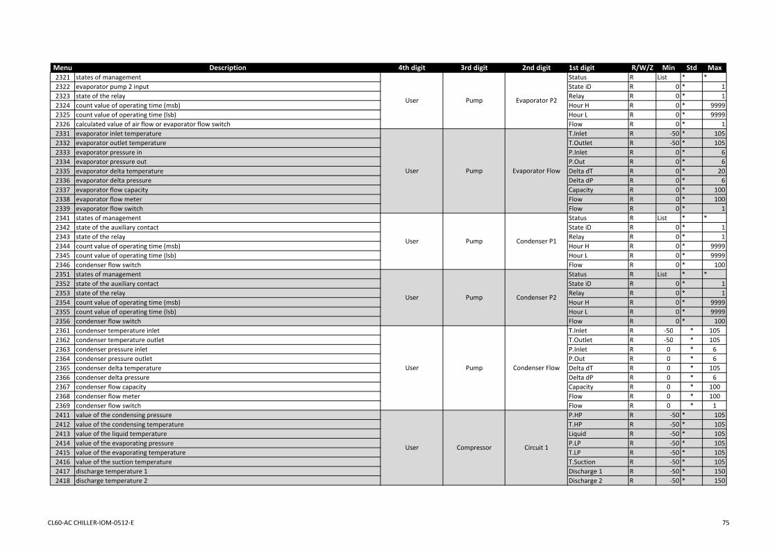
Menu Description 4th digit 3rd digit 2nd digit 1st digit R/W/Z Min Std Max2321 states of management Status R List * *2322 evaporator pump 2 input State iD R 0 * 12323 state of the relay Relay R 0 * 12324 count value of operating time (msb) Hour H R 0 * 99992325 count value of operating time (lsb) Hour L R 0 * 99992326 calculated value of air flow or evaporator flow switch Flow R 0 * 12331 evaporator inlet temperature T.Inlet R -50 * 1052332 evaporator outlet temperature T.Outlet R -50 * 1052333 evaporator pressure in P.Inlet R 0 * 62334 evaporator pressure out P.Out R 0 * 62335 evaporator delta temperature Delta dT R 0 * 202336 evaporator delta pressure Delta dP R 0 * 62337 evaporator flow capacity Capacity R 0 * 1002338 evaporator flow meter Flow R 0 * 1002339 evaporator flow switch Flow R 0 * 12341 states of management Status R List * *2342 state of the auxiliary contact State iD R 0 * 12343 state of the relay Relay R 0 * 12344 count value of operating time (msb) Hour H R 0 * 99992345 count value of operating time (lsb) Hour L R 0 * 99992346 condenser flow switch Flow R 0 * 1002351 states of management Status R List * *2352 state of the auxiliary contact State iD R 0 * 12353 state of the relay Relay R 0 * 12354 count value of operating time (msb) Hour H R 0 * 99992355 count value of operating time (lsb) Hour L R 0 * 99992356 condenser flow switch Flow R 0 * 1002361 condenser temperature inlet T.Inlet R -50 * 1052362 condenser temperature outlet T.Outlet R -50 * 1052363 condenser pressure inlet P.Inlet R 0 * 62364 condenser pressure outlet P.Out R 0 * 62365 condenser delta temperature Delta dT R 0 * 1052366 condenser delta pressure Delta dP R 0 * 62367 condenser flow capacity Capacity R 0 * 1002368 condenser flow meter Flow R 0 * 1002369 condenser flow switch Flow R 0 * 12411 value of the condensing pressure P.HP R -50 * 1052412 value of the condensing temperature T.HP R -50 * 1052413 value of the liquid temperature Liquid R -50 * 1052414 value of the evaporating pressure P.LP R -50 * 1052415 value of the evaporating temperature T.LP R -50 * 1052416 value of the suction temperature T.Suction R -50 * 1052417 discharge temperature 1 Discharge 1 R -50 * 1502418 discharge temperature 2 Discharge 2 R -50 * 150
Evaporator Flow
Condenser P1
Condenser P2
Condenser Flow
Circuit 1
Evaporator P2
Compressor
Pump
Pump
Pump
Pump
Pump
User
User
User
User
User
User
CL60-AC CHILLER-IOM-0512-E 75

Menu Description 4th digit 3rd digit 2nd digit 1st digit R/W/Z Min Std Max2421 state of configuration Config. R * * *2422 states of management Status R List * *2423 state of the auxiliary contact State iD R 0 * 12424 state of the relay Relay R 0 * 12425 count value of operating time (msb) Time H R 0 * 99992426 count value of operating time (lsb) Time L R 0 * 99992427 start counter high (msb) example : 456 Start H R 0 * 99992428 start counter low (lsb) example 123 Start L R 0 * 99992431 state of configuration Config. R * * *2432 states of management Status R List * *2433 state of the auxiliary contact State iD R 0 * 12434 state of the relay Relay R 0 * 12435 count value of operating time (msb) Time H R 0 * 99992436 count value of operating time (lsb) Time L R 0 * 99992437 start counter high (msb) example : 456 Start H R 0 * 99992438 start counter low (lsb) example 123 Start L R 0 * 99992441 state of configuration Config. R * * *2442 states of management Status R List * *2443 state of the auxiliary contact State iD R 0 * 12444 state of the relay Relay R 0 * 12445 count value of operating time (msb) Time H R 0 * 99992446 count value of operating time (lsb) Time L R 0 * 99992447 start counter high (msb) example : 456 Start H R 0 * 99992448 start counter low (lsb) example 123 Start L R 0 * 99992451 value of the condensing pressure P.HP R -50 * 1052452 value of the condensing temperature T.HP R -50 * 1052453 value of the liquid temperature Liquid R -50 * 1052454 value of the evaporating pressure P.LP R -50 * 1052455 value of the evaporating temperature T.LP R -50 * 1052456 value of the suction temperature T.Suction R -50 * 1052457 discharge temperature 1 Discharge 1 R -50 * 1502458 discharge temperature 2 Discharge 2 R -50 * 1502461 state of configuration Config. R * * *2462 states of management Status R List * *2463 state of the auxiliary contact State iD R 0 * 12464 state of the relay Relay R 0 * 12465 count value of operating time (msb) Time H R 0 * 99992466 count value of operating time (lsb) Time L R 0 * 99992467 start counter high (msb) example : 456 Start H R 0 * 99992468 start counter low (lsb) example 123 Start L R 0 * 99992471 state of configuration Config R * * *2472 states of management Status R List * *2473 state of the auxiliary contact State iD R 0 * 12474 state of the relay Relay R 0 * 12475 count value of operating time (msb) Time H R 0 * 99992476 count value of operating time (lsb) Time L R 0 * 99992477 start counter high (msb) example : 456 Start H R 0 * 99992478 start counter low (lsb) example 123 Start L R 0 * 9999
Circ.2 Comp.2
Circ.1 Comp.1
Circ.1 Comp.2
Circ.1 Comp.3
Circuit 2
Circ.2 Comp.1
Compressor
Compressor
Compressor
Compressor
Compressor
Compressor
User
User
User
User
User
User
CL60-AC CHILLER-IOM-0512-E 76
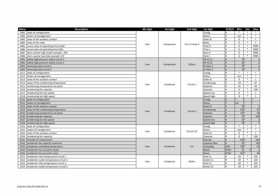
Menu Description 4th digit 3rd digit 2nd digit 1st digit R/W/Z Min Std Max2481 state of configuration Config R * * *2482 states of management Status R List * *2483 state of the auxiliary contact State iD R 0 * 12484 state of the relay Relay R 0 * 12485 count value of operating time (msb) Time H R 0 * 99992486 count value of operating time (lsb) Time L R 0 * 99992487 start counter high (msb) example : 456 Start H R 0 * 99992488 start counter low (lsb) example 123 Start L R 0 * 99992491 safety high pressure switch circuit 1 HP iD C1 R 0 * 12492 safety high pressure switch circuit 2 HP iD C2 R 0 * 12493 reversing valve circuit 1 R.Valve 1 R 0 * 12494 reversing valve circuit 2 R.Valve 2 R 0 * 12511 state of configuration Config. R * * *2512 states of management Status R List * *2513 state of the auxiliary contact State iD R 0 * 12514 value of the condensing temperature Condensing R -50 * 672515 condensing temperature set point Setpoint R 25 * 452516 condensing fan capacity Capacity R 0 * 1002517 condensing fan low speed Speed Low R 0 * 12518 condensing fan high speed Speed High R 0 * 12521 state of configuration Config. R * * *2522 states of management Status R List * *2523 state of the auxiliary contact State iD R 0 * 12524 value of the condensing temperature Condensing R -50 * 672525 condensing temperature set point Setpoint R 25 * 452526 condensing fan capacity Capacity R 0 * 1002527 condensing fan low speed Speed Low R 0 * 12528 condensing fan high speed Speed High R 0 * 12531 state of configuration Config R * * *2532 states of management Status R List * *2533 state of the auxiliary contact State iD R 0 * 12534 condensing fan capacity Capacity R 0 * 1002541 Outside air temperature Outside R -50 * 1052542 condenser fan capacity maximum Capacity Max R 0 * 1002543 condenser unloading temperature Unloading R/W 50 * 652544 condenser fan accoustic mode Mode R/WZ 0 0 22545 condenser fan accoustic noise Noise R/WZ 82 * 942551 condenser inlet temperature circuit 1 Inlet C1 R -50 * 1052552 condenser outlet temperature circuit 1 Outlet C1 R -50 * 1052553 condenser inlet temperature circuit 2 Inlet C2 R -50 * 1052554 condenser outlet temperature circuit 2 Outlet C2 R -50 * 105
Circ.2 Comp.3
Others
Circuit 1
Circuit 2
Circuit 1/2
Fan
Water
Condenser
Condenser
Condenser
Condenser
Compressor
Compressor
Condenser
User
User
User
User
User
User
User
CL60-AC CHILLER-IOM-0512-E 77

Menu Description 4th digit 3rd digit 2nd digit 1st digit R/W/Z Min Std Max2611 state of configuration Config. R * * *2612 states of management Status R List * *2613 value of the evaporating pressure Saturated R 0 * 202614 value of the evaporating temperature Saturated R -4 * 352615 value of the suction temperature Suction R -50 * 1052616 value of superheat S.Heat R 0 * 1052617 set point of superheat Setpoint R 5 * 152618 opening percentage calculated for the valve Capacity R 0 * 1002619 opening steps calculated for the valve Step R 0 * ETS50 = 26252621 state of configuration Config R * * *2622 states of management Status R List * *2623 value of the evaporating pressure Saturated R 0 * 202624 value of the evaporating temperature Saturated R -4 * 352625 value of the suction temperature Suction R -50 * 1052626 value of superheat Superheat R 0 * 1052627 set point of superheat Setpoint R 5 * 152628 opening percentage calculated for the valve Capacity R 0 * 1002629 opening steps calculated for the valve Step R 0 * ETS50 = 2625ETS100 = 36302711 state of configuration Config. R * * *2712 states of management Status R List * *2713 input of the freecooling State iD R 0 * 12714 freecooling valve Valve R 0 * 12715 outside air temperature Outside R -50 * 1052716 inlet coil water temperature Inlet R -50 * 1052717 inlet coil water reference temperature Inlet Ref. R -50 * 1052718 outlet coil water temperature Outlet R -50 * 1052719 freecooling capacity Capacity R 0 * 1002721 state of configuration Config. R * * *2722 states of management Status R List * *2723 state of the auxiliary contact State iD R 0 * 12731 state of configuration Config. R * * *2732 states of management Status R List * *2733 evaporator outlet temperature Outlet R -50 * 1052734 electrical heater capacity Capacity R 0 * 1002735 electrical heater input State iD R 0 * 12736 electrical heater output 1 Output 1 R 0 * 12737 electrical heater output 2 Output 2 R 0 * 12738 electrical heater output 3 Output 3 R 0 * 12739 electrical heater output 4 Output 4 R 0 * 12741 state of configuration Config. R 1 * 22742 value of the real power Real Pw R 2 * 32743 value of the reactive power Reac.Pw R 3 * 42744 value of the power factor P-Factor R 4 * 52745 value of the active energy (msb) Activ.E H R 5 * 62746 value of the active energy (lsb) Activ.E L R 6 * 72747 value of the reactive energy (msb) Reac.E H R 7 * 82748 value of the reactive energy (lsb) Reac.E L R 8 * 9
User Option Freecooling
FP Correct
Heater Elec
Circuit 1
Circuit 2
Expansion Valve
Expansion Valve
Option
Option
User
User
User
User
User Option Power Meter
CL60-AC CHILLER-IOM-0512-E 78

Menu Description 4th digit 3rd digit 2nd digit 1st digit R/W/Z Min Std Max2811 state of configuration Config. R * * *2812 states of management Status R List * *2813 address of the unit (bus id) Address R 1 * 82814 outside air reference temperature Outside R -50 * 1052815 evaporator inlet reference temperature Inlet R -50 * 1052816 evaporator outlet reference temperature Outlet R -50 * 1052817 unit number priority to start Priority R 1 * 82818 unit number in standby Standby R 1 * 82819 unit number to start next Next Start R 1 * 82821 states of management Status R List * *2822 outside air reference temperature Outside R -50 * 1052823 evaporator inlet reference temperature Inlet R -50 * 1052824 evaporator outlet reference temperature Outlet R -50 * 1052825 watchdog timer Watchdog R/W 1 * 82826 address of the unit (bus id) Address R/W 1 * 82827 setting of the protocol type Type R/W 0 0 72828 configuration of communication bus speed Baud R/W 0 0 2
Master/Slaves
BmsLink
LinkUser
User
CL60-AC CHILLER-IOM-0512-E 79

Menu Description 4th digit 3rd digit 2nd digit 1st digit R/W/Z Min Std Max3111 general on/off On/Off R/W 0 0 13112 remote on/off On/Off iD R/W 0 * 13113 enable On/Off Mode R/W/Z 0 1 13114 Lennox technician Test R/W 0 0 103115 reset the active alarm(s) Reset Alarm R/W 0 0 13116 clear the historic of alarm(s) Clear Alarm R/W 0 0 13117 electrical box temperature Box Tß R -50 * 1053118 general status of the unit Status R List * *3121 unit range configuration Range R/W 0 0 83122 unit size configuration Size R/W List * *3123 unit capacity configuration Capacity R/W 0 * 1003124 glycol rate configuration Glycol R/W 0 0 503125 restore the settings parameters Restore R/W 0 0 53131 configuration of the free output bm.no7 Bm-N7 R/W 3132 configuration of the free output be.no1 Be.1-N1 R/W 3133 configuration of the free output be.no2 Be.1-N2 R/W 3134 configuration of the free output be.no3 Be.1-N3 R/W 3135 configuration of the free output be.no4 Be.1-N4 R/W 3141 configuration of the free input bm.id4 Bm-iD4 R/W 3142 configuration of the free input bm.id7 Bm-iD7 R/W 3143 configuration of the free input be.id1 Be.1-iD1 R/W 3144 configuration of the free input be.id2 Be.1-iD2 R/W 3145 configuration of the free input be.id3 Be.1-iD3 R/W 3146 configuration of the free input be.id4 Be.1-iD4 R/W 3151 configuration of the free input be.b1 Be.1-B1 R/W 3152 configuration of the free input be.b2 Be.1-B2 R/W 3153 configuration of the free input be.b3 Be.1-B3 R/W 3154 configuration of the free input be.b4 Be.1-B4 R/W 3161 evaporator pump(s) configuration Pump Evap. R/W 0 * *3162 condenser pump(s) configuration Pump Cond. R/W 0 * *3163 Display(s) configuration Display R/W 0 0 33164 electronic expansion valve configuration EEV Driver R/W 0 0 13165 power meter configuration Heater Elec R/W 0 0 13166 electrical heater configuration Freecooling R/W 0 0 13167 inverter for condenser fan configuration Fan % R/W 0 0 13168 power factor correction configuration Power Factor R/W 0 0 13169 power meter configuration Power meter R/W 0 0 13211 evaporator inlet probe temperature Inlet R -50 * 1053212 evaporator inlet reference temperature Inlet Ref R -50 * 1053213 evaporator outlet probe temperature Outlet R -50 * 1053214 evaporator outlet reference temperature Outlet Ref R -50 * 1053215 evaporator delta temperature (inlet-outlet) Delta Tß R 0 * 1053216 evaporator set point Setpoint R -10 * 503217 evaporator capacity Capacity R 0 * 1003218 evaporator flow switch Flow R 0 * 1
Option
Temperature
General
Configuration
Cust. Relay
Cust. Switch
Cust. Signal
Unit
Unit
Unit
Unit
Unit
Unit
Water
Expert
Expert
Expert
Expert
Expert
Expert
Expert
CL60-AC CHILLER-IOM-0512-E 80

Menu Description 4th digit 3rd digit 2nd digit 1st digit R/W/Z Min Std Max3221 changeover status Status R List * *3222 outside air probe temperature Outside R -50 * 1053223 outside air reference temperature Outside Ref. R -50 * 1053224 changeover mode Mode R/W/Z 3225 winter air temperature to swap in heating mode AirTßWinter R/W -10 18 303226 summer air temperature to swap in cooling mode AirTßSummer R/W 19 23 303231 evaporator status Status R List * *3232 evaporator inlet reference temperature Inlet R -50 * 1053233 evaporator outlet reference temperature Outlet R -50 * 1053234 evaporator set point Setpoint R -10 * 503235 evaporator cooling capacity Capacity R 0 * 1003236 outside air set point x1 in cool Air Slope 1 R/W/Z -11 22 503237 outside air set point x2 in cool Air Slope 2 R/W/Z -11 30 503238 evaporator set point y1 in cool Water 1 R/W/Z 19 7 203239 evaporator set point y2 in cool Water 2 R/W/Z 19 7 203241 evaporator status Status R List * *3242 evaporator inlet reference temperature Inlet R -50 * 1053243 evaporator outlet reference temperature Outlet R -50 * 1053244 evaporator set point Setpoint R -10 * 503245 evaporator heating capacity Capacity R 0 * 1003246 outside air set point x1 in heat Air Slope 1 R/W/Z -11 22 503247 outside air set point x2 in heat Air Slope 2 R/W/Z -11 30 503248 evaporator set point y1 in heat Water 1 R/W/Z 40 45 503249 evaporator set point y2 in heat Water 2 R/W/Z 40 45 503251 external evaporator set point Sp 4/20mA R 4 * 203252 external offset evaporator set point Sp +/-1ßC R -1 * 13253 second set point switch status Sp Nß2 R 0 * 13261 evaporator cooling delta temperature Cool dTß R/W 1 5 203262 evaporator heating delta temperature Heat dTß R/W 1 5 203263 evaporator water reactivity Reactivity R/W 1 15 1203271 evaporator cooling low safety temperature Cool Low R/W 3 5 553272 evaporator cooling high safety temperature Cool High R/W 19 55 553273 evaporator heating low safety temperature Heat Low R/W 3 5 553274 evaporator heating high safety temperature Heat High R/W 19 55 553311 evaporator pump 1 status Status R List * *3312 evaporator pump 1 input State iD R 0 * 13313 evaporator pump 1 output Output R 0 * 13314 count value of operating time (msb) Hour H R 0 * 99993315 count value of operating time (lsb) Hour L R 0 * 99993316 evaporator flow switch Flow R 0 * 13321 evaporator pump 2 status Status R List * *3322 evaporator pump 2 input State iD R 0 * 13323 evaporator pump 2 output Output R 0 * 13324 count value of operating time (msb) Hour H R 0 * 99993325 count value of operating time (lsb) Hour L R 0 * 99993326 evaporator flow switch Flow R 0 * 1
Changeover
Cooling
Evaporator P2
Heating
Custom
Control
Safety
Evaporator P1
Water
Water
Water
Water
Water
Water
Pump
Pump
Expert
Expert
Expert
Expert
Expert
Expert
Expert
Expert
CL60-AC CHILLER-IOM-0512-E 81

Menu Description 4th digit 3rd digit 2nd digit 1st digit R/W/Z Min Std Max3331 evaporator inlet temperature T.In R -50 * 1053332 evaporator outlet temperature T.Out R -50 * 1053333 evaporator pressure in P.In R 0 * 63334 evaporator pressure out P.Out R 0 * 63335 evaporator delta temperature Delta dT R 0 * 1053336 evaporator delta pressure Delta dP R 0 * 63337 evaporator flow capacity Capacity R 0 * 1003338 evaporator flow meter Flow R 0 * 1003339 evaporator flow switch Flow R 0 * 13341 evaporator pump(s) enable Priority R/W/Z 0 0 73342 evaporator pump(s) reset counter Reset R/W 0 0 23343 evaporator pump(s) operating mode Mode R/W 0 0 43344 evaporator variable flow delta temperature Delta dT R/W 2 * 103345 evaporator variable flow delta pressure Delta dP R/W 1 1 63346 evaporator variable flow output pressure P.Out R/W 0,5 1 63347 evaporator variable flow minimum Flow Min R/W 60 60 1003348 evaporator variable flow maximum Flow Max R/W 60 100 1003351 condenser pump 1 status Status R List * *3352 condenser pump 1 input State iD R 0 * 13353 condenser pump 1 output Output R 0 * 13354 count value of operating time (msb) Hour H R 0 * 99993355 count value of operating time (lsb) Hour L R 0 * 99993356 condenser flow switch Flow R 0 * 1003361 condenser pump 2 status Status R List * *3362 condenser pump 2 input State iD R 0 * 13363 condenser pump 2 output Output R 0 * 13364 count value of operating time (msb) Hour H R 0 * 99993365 count value of operating time (lsb) Hour L R 0 * 99993366 condenser flow switch Flow R 0 * 1003371 condenser temperature inlet T.In R -50 * 1053372 condenser temperature outlet T.Out R -50 * 1053373 condenser pressure inlet P.In R 0 * 63374 condenser pressure outlet P.Out R 0 * 63375 condenser delta temperature Delta dT R 0 * 1053376 condenser delta pressure Delta dP R 0 * 63377 condenser flow capacity Capacity R 0 * 1003378 condenser flow meter Flow R 0 * 1003379 condenser flow switch Flow R 0 * 13381 condenser pump(s) enable Priority R/W/Z 0 0 73382 condenser pump(s) reset counter Reset R/W 0 0 23383 condenser pump(s) operating mode Mode R/W 0 0 43384 condenser variable flow delta temperature Delta dT R/W 2 * 103385 condenser variable flow delta pressure Delta dP R/W 1 1 63386 condenser variable flow output pressure P.Out R/W 0,5 1 63387 condenser variable flow minimum Flow Min R/W 60 60 1003388 condenser variable flow maximum Flow Max R/W 60 100 100
Evaporator Flow
Evaporator Control
Condenser P1
Condenser P2
Condenser Flow
Condenser Control
Pump
Pump
Pump
Pump
Pump
Pump
Expert
Expert
Expert
Expert
Expert
Expert
CL60-AC CHILLER-IOM-0512-E 82

Menu Description 4th digit 3rd digit 2nd digit 1st digit R/W/Z Min Std Max3411 value of the condensing pressure P.HP R -50 * 1053412 value of the condensing temperature T.HP R -50 * 1053413 value of the liquid temperature Liquid R -50 * 1053414 value of the evaporating pressure P.LP R -50 * 1053415 value of the evaporating temperature T.LP R -50 * 1053416 suction temperature circuit 1 T.Suction R -50 * 1053417 discharge temperature 1 circuit 1 Discharge 1 R -50 * 1503418 discharge temperature 2 circuit 1 Discharge 2 R -50 * 1503421 value of the condensing pressure P.HP R -50 * 1053422 value of the condensing temperature T.HP R -50 * 1053423 value of the liquid temperature Liquid R -50 * 1053424 value of the evaporating pressure P.LP R -50 * 1053425 value of the evaporating temperature T.LP R -50 * 1053426 suction temperature circuit 2 T.Suction R -50 * 1053427 discharge temperature 1 circuit 2 Discharge 1 R -50 * 1503428 discharge temperature 2 circuit 2 Discharge 2 R -50 * 1503431 compressor(s) enable circuit 1 Enable C1 R/W/Z 0 0 73432 compressor(s) enable circuit 2 Enable C2 R/W/Z 0 0 73433 compressor(s) reset counter circuit 1 Clear C1 R/W 0 0 73434 compressor(s) reset counter circuit 2 Clear C2 R/W 0 0 73435 compressor(s) circuit priority Priority R/W 0 0 33441 evaporator saturation safety temperature Saturation R/W -6 -6 53442 condenser unloading safety temperature Unloading R/W 50 63 653443 compressor discharge safety temperature Discharge R/W 90 120 1503511 configuration condenser circuit 1 Config R * * *3512 status condenser circuit 1 Status R List * *3513 input condenser circuit 1 State iD R 0 * 13514 condensing temperature circuit 1 Condensing R -50 * 673515 condensing temperature set point Setpoint R 25 * 453516 condensing fan capacity circuit 1 Capacity R 0 * 1003517 condensing fan low speed circuit 1 Speed Low R 0 * 13518 condensing fan high speed circuit 1 Speed High R 0 * 13521 configuration condenser circuit 2 Config R * * *3522 status condenser circuit 2 Status R List * *3523 input condenser circuit 2 State iD R 0 * 13524 condensing temperature circuit 2 Condensing R -50 * 673525 condensing temperature set point Setpoint R 25 * 453526 condensing fan capacity circuit 2 Capacity R 0 * 1003527 condensing fan low speed circuit 2 Speed Low R 0 * 13528 condensing fan high speed circuit 2 Speed High R 0 * 13531 configuration condenser circuit 1&2 Config R * * *3532 status condenser circuit 1&2 Status R List * *3533 input condenser circuit 1&2 State iD R 0 * 13534 condensing fan capacity circuit 1&2 Capacity R 0 * 100
Safety
Circuit 1
Circuit 2
Circuit 1/2
Circuit 1
Circuit 2
Enable
Compressor
Compressor
Compressor
Compressor
Condenser
Condenser
Condenser
Expert
Expert
Expert
Expert
Expert
Expert
Expert
CL60-AC CHILLER-IOM-0512-E 83

Menu Description 4th digit 3rd digit 2nd digit 1st digit R/W/Z Min Std Max3541 condenser fan capacity maximum Capacity Max R 0 * 1003542 condenser unloading temperature Unloading R 50 * 653543 condenser fan accoustic mode Mode R/W 0 0 23544 condenser fan accoustic noise Noise R/W 82 * 943545 condenser fan set point Setpoint R/W 35 40 453546 condenser fan set point low speed on Speed L.On R/W 30 46 603547 condenser fan set point low speed off Speed L.Off R/W 30 38 603548 condenser fan set point high speed on Speed H.On R/W 30 58 603549 condenser fan set point high speed off Speed H.Off R/W 30 49 603551 condenser inlet temperature circuit 1 Inlet C1 R -50 * 1053552 condenser outlet temperature circuit 1 Outlet C1 R -50 * 1053553 condenser inlet temperature circuit 2 Inlet C2 R -50 * 1053554 condenser outlet temperature circuit 2 Outlet C2 R -50 * 1053561 defrost mode Mode R 0 0 13562 outside air defrost temperature Outside R 8 16 223563 evaporator saturation defrost temperature Saturation R -10 1,7 103564 defrost frequency delay Freq R 30 45 903565 Ratio for dynamic management C1 dLP C1 R/W -50 * 1053566 Ratio for dynamic management C1 dLP C2 R/W -50 * 1053567 Circuit 1 counter between defrost Counter C1 R/W 30 * 903568 Circuit 1 counter between defrost Counter C2 R/W 30 * 903571 condenser cooling low safety temperature Safety Low R/W 3 5 553572 condenser cooling high safety temperature Safety High R/W 19 55 553573 condenser heating low safety temperature * R/W 3 5 553574 condenser heating high safety temperature * R/W 19 55 553611 state of configuration Config R * * *3612 states of management Status R List * *3613 value of the evaporating pressure Saturated R 0 * 203614 value of the evaporating temperature Saturated R -4 * 353615 value of the suction temperature Suction R -50 * 1053616 value of superheat Superheat R 0 * 1053617 set point of superheat Setpoint R 5 * 153618 opening percentage calculated for the valve Capacity R 0 * 1003619 opening steps calculated for the valve Step R 0 * 26253621 state of configuration Config R * * *3622 states of management Status R List * *3623 value of the evaporating pressure Saturated R 0 * 203624 value of the evaporating temperature Saturated R -4 * 353625 value of the suction temperature Suction R -50 * 1053626 value of superheat Superheat R 0 * 1053627 set point of superheat Setpoint R 5 * 153628 opening percentage calculated for the valve Capacity R 0 * 1003629 opening steps calculated for the valve Step R 0 * 26253631 set point of superheat Expert Expansion Valve Control Superheat R/W 5 * 15
Circuit 1
Circuit 2
Fan
Water
Defrost
Safety
Condenser
Condenser
Condenser
Condenser
Expansion Valve
Expansion Valve
Expert
Expert
Expert
Expert
Expert
Expert
CL60-AC CHILLER-IOM-0512-E 84

Menu Description 4th digit 3rd digit 2nd digit 1st digit R/W/Z Min Std Max3711 configuration of the freecooling Config R * * *3712 status of freecooling Status R List * *3713 input of the freecooling State iD R 0 * 13714 freecooling valve Valve R 0 * 13715 outside air temperature Outside R -50 * 1053716 inlet coil water temperature Inlet R -50 * 1053717 inlet coil water reference temperature Inlet Ref. R -50 * 1053718 outlet coil water temperature Outlet R -50 * 1053719 freecooling capacity Capacity R 0 * 1003721 configuration of the power factor correction Config R * * *3722 status of the power factor correction Status R List * *3723 input of the power factor correction State iD R 0 * 13731 configuration of the electrical heater Config R * * *3732 status of the electrical heater Status R List * *3733 evaporator outlet temperature Outlet R -50 * 1053734 electrical heater capacity Capacity R 0 * 1003735 electrical heater input State iD R 0 * 13736 electrical heater output 1 Output 1 R 0 * 13737 electrical heater output 2 Output 2 R 0 * 13738 electrical heater output 3 Output 3 R 0 * 13739 electrical heater output 4 Output 4 R 0 * 13741 configuration of the power meter Config R * * *3742 value of the real power Real Pw R 0 * 999993743 value of the reactive power Reac.Pw R 0 * 999993744 value of the power factor P-Factor R 0 * 999993745 value of the active energy (msb) Activ.E H R 0 * 999993746 value of the active energy (lsb) Activ.E L R 0 * 999993747 value of the reactive energy (msb) Reac.E H R 0 * 999993748 value of the reactive energy (lsb) Reac.E L R 0 * 999993749 reset all counter Clear Counter R/W 0 0 13811 status of the master/slave link Status R List * *3812 outside air reference temperature Outside R -50 * 1053813 evaporator inlet reference temperature Inlet R -50 * 1053814 evaporator outlet reference temperature Outlet R -50 * 1053815 address of the board Adress R/W 1 * 83816 number of units linked Number R/W 1 * 83817 master/slave configuration Type R/W 0 0 73818 outside air temperature configuration TßAir R/W 0 0 23819 evaporator water temperature configuration TßWater R/W 0 0 23821 status of the BMS Status R List * *3822 outside air BMS temperature Outside R -50 * 1053823 evaporator inlet BMS temperature Inlet R -50 * 1053824 evaporator outlet BMS temperature Outlet R -50 * 1053825 watchdog timer Watchdog R/W 0 * 320003826 identification number configuration Id R/W 1 * 1993827 BMS protocol configuration Protocol R/W 0 0 63828 BMS bauderate configuration Baud. R/W 0 0 4
Freecooling
BMS
FP Correct
Heater Elec
Power Meter
Master/Slaves
Option
Option
Option
Link
Link
Option
Expert
Expert
Expert
Expert
Expert
Expert
CL60-AC CHILLER-IOM-0512-E 85


www.lennoxeurope.com
+7 495 626 56 53
+34 902 533 920
+380 44 461 87 79
+44 1604 669 100
+ 32 3 633 3045
+33 1 64 76 23 23
+49 (0) 6071 3915919
+ 39 02 495 26 200
+ 31 332 471 800
+48 22 58 48 610
+351 229 066 050
LENNOX DISTRIBUTION
+33 4 72 23 20 00
Due to Lennox’s ongoing commitment to quality, the specifi cations, ratings and dimensions are subject to change without notice and without incurring liability.Improper installation, adjustment, alteration, service or maintenance can cause property damage or personal injury.Installation and service must be performed by a qualifi ed installer and servicing agency
RUSSIA
SPAIN
UKRAINE
UNITED KINGDOM AND IRELAND
BELGIUM AND LUXEMBOURG
FRANCE
GERMANY
ITALY
NETHERLANDS
POLAND
PORTUGAL
SALES OFFICES :
OTHER COUNTRIES :
CL60 AC-CHILLER-IOM-0512-E