clearwater beach, florida - heavy movable structures · 2017-12-08 · desiqn considerations for...
TRANSCRIPT

Heavy Movable Structures, Inc.
SIXTH BIENNIAL SYMPOSIUM
October 30 - November 1, 1996
Doubletree Resort Surfside Clearwater Beach, Florida
Design Considerations for Bridge Hydraulics
Parveen Gupta, Mannesmann Rexroth
DESIGN CONSIDERATIONS FOR BRIDGE HYDRAULICS
by Parveen Gupta Marketing Manager
Hydraulics for Civil Engineering Mannesmann Rexroth
Bethlehem, PA.

Desiqn Considerations for Bridge Hvdraulics
by Parveen Gupta Mannesmann Rexroth
Traditionally, electro-mechanical drives have been used to operate steel
structures like Bascule, lift or swing type bridges. These drives, though reliable, are
custom built and need constant maintenance. AIso, transmitting the power over large
distances, stringent safety regulation and high demands on controls make hydraulic
drives (and controls) the more obvious choice.
Properly designed electro-hydraulic systems provide an economical and simple
solution to today's complex needs. Advent of microprocessor has increased the scope
of these drives tremendously.
A well designed hydraulic drive system, environmentally friendly fluids and high
pressure hydraulics will enhance the use of electro-hydraulic drives for movable bridges
and steel structures enormously.
Like any other machinery, a well designed hydraulic system must be simple, easy
to operate and maintain and use commercially available standard components as much
as possible.
Typical hydraulic system can be divided into the following three sections:
A) Power Source (Hydraulic Power Unit)
B) Power Transmission
C) Power Consumption (Hydraulic Cylinders or Motors).
A) Hvdraulic Power Unit (HPU):
HPU is the key design item for most hydraulic systems. There are some
standard HPU's but in general for bridges and other demanding applications, they are
custom designed and built to suit to specific application requirements

The HPU consists of:
Oil reservoir (and instrumentation)
Hydraulic pumps / motors and engines
Control valves and manifolds
Fluid conditioning
Lavout
Following are the more common power unit layouts (Figures 1, 2 & 3)
- Pump 1 motor group on top of the tank (Horizontal or Vertical)
- Pump 1 motor below the tank (overhead design)
- Pump / motor in front of the tank (L shape layout)
or a combination of the above three options is also fairly common.
For extended pump life and ease of operation and maintenance, L shaped power
unit layout is most preferred.
For quiet pump operation, it is common to install the pump 1 motor vertically on
the tank top with the pump inside of the tank. This design offers convenient plumbing
and quiet system operation. Pump maintenance and pump control adjustments are a bit
more involved though.
Figure 1.

Figure 2.

Figure 3.

Oil Reservoirs:
In addition to serving as the oil storage t 1; the reservoir also provides for time
and area needed for oil to cool down and settle dawn to de-aerate. Typically oil reservoir
also has provision for instrumentation, i.e. temperature switch / tclermometer, level
switches, etc.
A well designed HPU must have safety guards for mechanical protection of sight
gauges and other level temperature switches.
In general, for the intermittent duty cycle typical of all bridge hydraulics, there is
no need for an oil cooler. Olr heating sometimes may be needed for colder weather.
Based on our experience, we try to avoid heaters because the oil closest to the heating
elements may get overheated and burn. Thus, we prefer to select the proper oil for the
temperature range rather than use oil heaters. If oil heating is still needed, it can be
accomplished by heating the oil over the pressure relief valve.
Therefore, the oil reservoir serves many purposes and must be well designed to
take the load of components on it, store oil. and must be properly baffled to allow the oil
to cool down and de-aerate. Stainless steel tanks keep the oil clean and offer lasting
soiutions for proportional val~le systems as used in bridges.
As a good design pr, ,Ice the oil tank should be on a base frame with a drip pan
in all needed areas. The base frame and drip pan should be strong enough to handle
transportation, normal operational vibration and common maintenance needs.
Pump / Motor Groups
Pump and motor should be coup. sing heavy duty couplir- To ensure that
the two items are always aligned, they should be close coupled using a C face mounting
preferably.
The pump / motor group should then be installed on properly designed and
machined sub-frame. The sub-frame in turn are connected to the base using shock
mounts to reduce the noise and vibrations. Different size and shape of st-rock mounts
are used based on the loading.

Control Valves and Manifolds
Manifolds are commonly used to reduce leakage potentials and put a large
quantity of valves in a smaller space. Also, it makes the system more responsive (lower
trapped oil volume) and easier to trouble shoot and maintain.
Use of manifolds is one of the easiest ways to reduce leakage potentials.
Fluid Conditioninq
It has been said that 80% of the problems in hydraulic systems are caused by
contamination. It is relatively simple to avoid contamination by installing a properly sized
pressure filter (downstream of the pump) and the return filter.
It is the author's opinion not to instal suction strainers as they are difficult to
maintain and may create problems in pump suction. The filter should always be sized
for the coolest oil temperature.
With the use of variable volume pumps, an oversized filter and flow meter in the
case drain line offers easy maintenance tips.
B. Power Transmission - Interconnectins Pipinq
To reduce noise and vibration, we prefer to have hoses on the pump's inlet and
outlet (and case drain). At most other locations, we prefer to have pipes or tubes of the
appropriate size. They should be supported every 6 feel if possible on the hydraulic
power unit itself.
We recommend appropriate size of the tube or pipe between the hydraulic power
unit and actuators. For cleaner solution, it should be of stainless steel.
Pipe should be of the butt welded type to ensure proper weld preparation, depth
of penetration and joint quality. To provide needed flexibiiity at the end of the pipe
lengths, there should be small hose lengths.
To avoid drift due to hose / pipe failures, needed control valves must be placed
as close to the cylinder or motor as possible (on them if possible).

Power Consumption:
The use of a hydraulic cylinder or hydra , motor and their design must be done
per the geometry requirements of the bridge and other circumstances.
In conclusion, I would like to make the following recommendations:
1) 3000 psi ncr; ' operating and 5000 psi peak pressure is pretty standard in the
industry. The e of higher pressure reduces the size of the actuators. pipes,
etc. and makes the system more con troll^
2) System must be well -! gineered, desig: dnd built to last. A:! 6 2ponents
must be of the highest industrial grade for long life and trouble free operation.
) Provisions should be made to make system more reliable (redundant pump /
motor, power failure back up, etc.).
4) Use more modern electronic control techniques for precision and controllability.
A well designed and professionally built hydraulic drive system needs very little
maintenance. So let's use high pressure hydraulics!

Heavy Movable Structures, Inc.
SIXTH BIENNIAL SYMPOSIUM
October 30 - November 1, 1996
Doubletree Resort Surfside Clearwater Beach, Florida
New Design Features and Guidelines for Hydraulic Cylinders
Charles A. Simons, Mannesmann Rexroth

New Design Features and Guidelines for Hydraulic Cylinders.
by
Charles A. Simons
Mannesmann Rexroth Hydraudyne Cylinders B.V. Kruisbroeksestraat 1 P.O. Box 32 5280 AA Boxtel the Netherlands
August 1, 1996

New Design Features and Guidelines for Hvdraulic p/ Cylinders
1 . htroductiogl During the 5th Biennial Symposium the proof of new technolorn such as the ceramic piston rod coating Ceramax and the to Cerarnax related Ceramax integrated Measuring System (CI,MS) was presented. This technology combined with proven in practice csnstmctisn details and experience with repiations results into appiication based standards or modules for Hydraulic Cylinders for bridges.
2. Projects The following 2 projects shows the specially for the application designed cylinders, with each their specific ci~aractexdstics:
Brickell Avenue.. Miami. FL The Brickell Ave-wue bridge (fig 1) is a newly built 4 leave "oascule bridge over the River h%ami, operated by 4 hydraulic cylinders per leave. The design of the cylinders are based on the earlier mentioned modules, involving Ceramax rod coating and the widely applied and proven standard seal and bearing design.
fig. 1. BrickelI Avenue Bridge

Erasmus Bridge. Rotterdam, the Netherlands The Erasmus Bridge is a 410 meter long a-symmetric suspension bridge (fig. 2), over the main waterway, River Maas, in Rotterdam harbor, combined with a single leave bascule bridge, 33.13 m wide, 57.8 m long. The 4 hydraulic cylinders, bore 600 mrn and stroke 6940 mm, are specially designed to meet the very strict requirements of the Rotterdam City Council and the manufacturer of the operating machinery. To measure the leave position, 2 cylinders are equipped with the CIMS position indicator.
fig. 2, Erasmus Bridge
3. Proven Technolorn Both the above mentioned projects clearly demonstrates the possibilities with modern technology. Past experience is the basis for the typical application based standard cylinder configuration for bridges complete with upper and lower mounting brackets as shown in fig. 3
fig. 3, Typical bridge cylinder

iln update in technoloav Continuous search for improvements demands for innovations. The vulnerable parts of cylinders are clearly the seals and the piston rod.
The classic sealing configurations uses chevron or multi-lip V packings. These Chewon seals are available only in NP3W or in Viton material and the cornrnerciaI availabiligr is restricted to standard dimensions only. Higher demands on life time (reduction of friction), speed other hydraulic mediums requires a development in seal design. Fundamenral research based on mathematical model of both the rod surFace and the seal parameters will direct the design of new and modern seal shapes and compounds. This development goes in the direaion s f low fricrion seals like step seals offbring a large variety in seal compounds, pressure range etc
To reach the optimum corrosion resistance the piston rod has to be coated with the ceramic pisto2 rod coating Ceramax. This is in the mean time a world-\.vade accepted standard. Salt spray testing proved the high corrosion resistance of the Ceramax. As Wexroth opted for a clear improvement of the corrosion resistance compared to the known piston rod coatings, such as chomiurn plating, the goal was setfor a corrosion resistance of at least 1000 hours salt spray testing. 1000 hours salt spray testing according ASTM C85 or DIN 50021 ESS is regarded as a bench mark for the highest corrosion protection level.
Rexroth Ilydraudyne in the Netherlands have developed the layer and production technoiogy for Ceramax. To obtain the homogenous, unintempted and non-conducting layer with the required quality (hardness and roughness), the coating process is controlled by a computer operation machine. The in house Geramax Coating Center is the proven source to secure Ceramax cylinders with high and consistent quality
Using "ie non-conduction properties of the Ceramax coating the position indicator CIMS (Ceramax Integrated hjeasuring System) is deveioped C M S has two hndamerttal adva~~tages for Civil Engineering applications: it is independent of the stroke length, extremely robust by virtue of the advan- ced ceramic coating technology used on the piston rods and it sensor located in the pressure less area in the cylinder, were it is not subject to influence from the outside. If required, two or three sensors can be placed in the packing fig. 4. CIMS mark IF flange to create redundancy
CIMS consists of3 main parts, the serrated Ceramax rods, the sensor and the electronics With CIMS mark I, the separate electronics box had to be mounted within 3 meters to the sensor VArh the second generation CIMS (iMar.rk 11) extensive miniaaurization has been achieved. With %his development it is made possible to combine the sensor md a minimum of electronics in one walenight housing. see fig 4 The incremental output signal (RS422 format) can lead over
long distances. T h e third generation CIMS is a absolute measuring system, which solves the undesirable loss of position after a power interruption. In that case a power back-up is no longer required. CIMS is compact and easily accessible for maintenance purposes.
4. Application based construction details
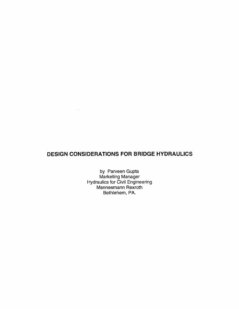
Buckling The lay-out and dimensions of a hydraulic cylinder is usually determined by maximum force and available pressure only. Mounting styles have a considerable impact on the stability of the total cylinder. For instance, a clevis to clevis mounting has a long center to center length compared to a front positioned trunnion and clevis. This difference in built-in length determines the allowable buckling load. Restricting the buckling length results in a reduced rod diameter and therefor costs, see fig 5.
fig. 5, Buckling situations
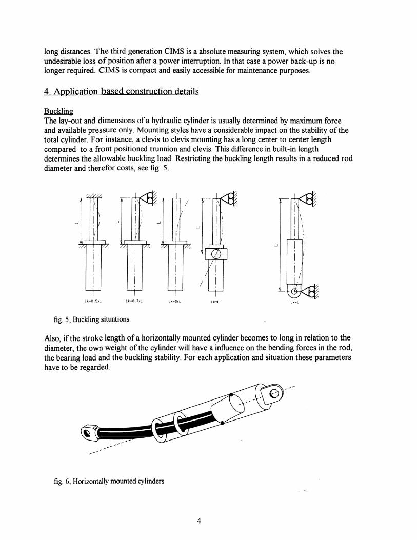
Also, if the stroke length of a horizontally mounted cylinder becomes to long in relation to the diameter, the own weight of the cylinder will have a influence on the bending forces in the rod, the bearing load and the buckling stability. For each application and situation these parameters have to be regarded.
fig. 6, Horizontally mounted cylinders

Cardanic Ring As mentioned earlier, a trunnion mounting reduces the buckling length. A trunnion has only one degree of freedom. If also alignment in the perpendicular axis of the trunnion is required, a gimbal mounting is the solution. This gimbal mounting uses a cardanic ring construction as per fig. 7. The ring is a one piece flame cutted part connected to the female trunnion on the cylinder shell with separate pins. This allows to disassemble the cardanic ring and replacing the wear parts in this construction without extensive re-machining of the cylinder. This cardanic ring construction is very compact, resulting in a minimal distance between the pillow blocks. With this reduced distance the bending in the ring is lower, thus the ring can de designed lighter.
fig. 7,
Cushionin The objecEve of cushioning is to reduce the speed of a moving mas$ whose center of gravity lies on the cylinder axis, to a level at which neither the cylinder nor the bridge can be damaged. The self-regulating end position cushioning, as shown in fig. 8 decelerates the cylinder and load to a acceptable metal to metal contact speed (< 0.1 dsec). The effective cushioning length adjusts automatically to the current requirements. In order to make the cushioning effective it must be preset based on data such as speed, moving weight, temperature etc.
fig. 8, Self regulating cushioning with integrated check valve
5

5. Guidelines Governmental organizations such as ASTM, AASHTO, DIN and ASME are there to guide the designers with minimum requirements and guard the users as much as possible for repeating problems. For an optimal result and cost effectiveness these guidelines have to be interpreted and used correctly. Hidden extra safety factors must be avoided. As an example for shell calculations, the ASME Boiler and Pressure Vessel Code calculates the wall thicknesses based on the tensile strength of the material. A much more to reality is to calculate to the yield of the material. The ratio yieldltensile is for every material different. With modern high strength materials the yield point is closer to the tensile strength, resulting in lighter constructions with maintaining the same safety factors.
Example design pressure P 2 1 N/mm2 Bore 360 mm Shell material MW450N
Yield 420 N/mmz Tensile 570 N/mmz
ASME BPVC The ASME wall thickness calculation is based on a safety factor of 4 to the tensile.
bore P*- 9
Wall thickness tensile
*E-0.6*P safety factor
Min. outside diameter 360 +2 *30.1 = 420.1 mm

DIN Standards The DIN standard requires a safety factor of 2.5 to the yield.
kin. outside diameter OD = ID*
1
safety factor
yze Id safety factor
This shows that an in depth calculation philosophy can result is a optimalization in weight and costs with maintaining a high standard safety. The applied safety factors can even be optimized by performing Finite Element calculations.
Conclusion The combination of experience, innovation and standardization offers safe, fit for use and cost effective products.
Boxtel, August 1, 1996