cleanroom product range - amazon s3s3.amazonaws.com/zanran_storage/ product range contents overview...
TRANSCRIPT

Cleanroom Product Range
2nd edition

Cleanroom Product Range
Issue 05/03, 2nd edition
Printed on paper free of
chlorine and acids, for the
benefit of our environment.
All technical data applies at
the time of going to print. All
texts, representations,
illustrations and drawings
included in this catalogue are
the intellectual property of
Festo AG & Co., and are
protected by copyright law. All
rights re-served, including
translation rights. No part of
this publication may be
reproduced or transmitted in
any form or by any means,
electronic, mechanical,
photocopying or otherwise,
without the prior written
permission of Festo AG & Co.
All technical data subject to
change according to technical
update.
Festo AG & Co.
P.O. Box
D-73726 Esslingen, Germany
Ruiter Strasse 82
D-73734 Esslingen, Germany

Foreword
Cleanroom Product Range from Festo
Changes in industrial production
have also resulted in changes in
the prevailing environmental
conditions. The demand for
quality has risen and the
reduction of costs has now
become the essential criterion.
Cleanroom production offers
considerable potential
here – as long as it is used
properly.
The more sensitive the item to be
produced, the “cleaner” the
production method required.
Production in cleanroom or using
cleanroom technology has
become increasingly popular.
However, it is not always
immediately obvious what
is actually behind it, never mind
how it should be used. Even the
concepts used to describe it are
often difficult to understand and
unclear.
Let us start with the concept of
the cleanroom. The only possible
method of cleanroom comparison
is based on the number of
airborne particles relative to a
volume equivalent. The VDI
Guideline 2083, the ISO 14644-1
and the US Federal Standard
209E have made a start by
defining international standards
for cleanliness classes.
One of the main factors that
influences air cleanliness is the
equipment installed in a
cleanroom. As a supplier of
automation expertise Festo has
been concerned with this subject
for over ten years. Back then the
number of customers in this
specialized area was small. That
has since changed.
The propagation of high-tech
chip development facilities, for
example, has resulted in a clear
increase in cleanroom
production.
Festo pneumatic products that
are suitable for used in
cleanroom ISO class 4
(FS209E class 10) and ISO
class 5 (FS209E class 100)
This catalogue cover both
standard Festo pneumatic
products and products that are
slightly modified to meet the
stringent requirements of
cleanroom ISO class 4 and
cleanroom ISO class 5 (i.e. US
Federal Standard 209E, class
10 and class 100).
Generally these products are
classified in the following
categories:
– Type RR: Are standard prod-
uct that are clean and pack.
Ready for cleanroom applica-
tion or replacement
– Type RR-SA: Are products
with slight modification
(usually come with a vacuum
suction port). They are clean
and pack, ready for clean-
room application or replace-
ment
All the products in this
catalogue are tested and
certified that the particle
emission level are within the
guideline and test procedures,
as stated in Chapter 4.
The products are then cleaned
and double packed before in-
house sending to the user.
The user is advised to remove
the first layer of packaging in a
clean area and the final
packaging inside the cleanroom
Festo pneumatic products that
are suitable for cleanroom ISO
class 6 (FS209E class 1000)
These standard products,
without any modification
needed, are tested and found
to be suitable for cleanroom
ISO class 6 (i.e. S Federal
Standard 209E class 1000).
Since they are standard
products, they can be order at
any Festo companies.
They are available in standard
packaging, the user are advice
to clean them before
introducing them into the
cleanroom.
These products are mentioned
only in the content pages but
the detail technical data are not
included in this catalogue, as
they are standard products.
The detail information of these
cleanroom ISO class 6 products
can be obtain on the CD-ROM
catalogue or any Festo
catalogue and brochure that
bears the information of the
products. User can also obtain
the necessary information on
the website: www.Festo.com
User are advice to use this
catalogue together with the
handbook “Fundamentals of
Cleanroom Technology”, part
no: 54078GB to gain more in
depth with cleanroom
technologies and qualifying
products for cleanroom
applications. The handbook
is available in all Festo
companies, worldwide.
What are the points to bear
in mind when using Festo
Cleanroom product range?
The specified values for
pressures, speeds, loads, lateral
forces, actuating forces, voltages,
magnetic fields and temperatures
should be adhered to at all times
and at any operational note
observed by the user to ensure
the correct functioning of the
equipment.
What are the points to bear
in mind when using this
catalogue?
All texts, representations,
illustrations and drawings
included in this publication are
the intellectual property of
Festo AG & Co., and are protected
by copyright law.
All rights reserved, including
translation rights. No part of this
publication may be reproduced or
transmitted in any form or by any
means, electronic, mechanical,
photocopying or otherwise,
without the prior written
permission of Festo AG & Co. All
technical data subject to change
according to technical update.
Festo AG & Co. shall not be held
liable for any damage, loss of
profit, consequential loss and/or
any other financial or technical
problems arising out of or in
connection with the use of the
products in this catalogue, if such
use is not in accordance within
the technical specification, the
manual and/or description in this
catalogue or in any other cases of
misuse of the products.
We wish you much success with
the Festo cleanroom product
range.
The Editor
Festo cleanroom product team

The cleanroom project initiated
by Festo is a collaboration among
Fraunhofer Institute for
Manufacturing Engineering and
Automation in Germany, Nanyang
Polytechnic (NYP) of Singapore
and Festo Singapore.
The objective is to work together
in the field of particle emission of
Festo products.
Furthermore, it is Festo’s
intention to improve the
experience in the field of particle
measurements, contamination
control as well as cleanroom
applications in general.
Introduction The Festo cleanroom project– a collaboration amongst 3 parties
Cleanroom Product Range from Festo AG & Co
Festo is doing the measure-
ment according the VDI 2083-8
guideline which is described on
page 82 and the following
pages. Fraunhofer Institute
approved this measurement
principle and attested this in a
‘Certificate of qualification’.
The certification covers: The
support for the performance of
testing the cleanroom suitabil-
ity of pneumatic components of
the company Festo AG & Co.
A sample of the product test
certificate, DGPL double acting
rodless cylinder is displayed.
Cleanroom Product Range Contents Overview
Introduction to cleanroom International standard of cleanroom Basic principles for designing cleanroom equip-ment Qualifying equipment for cleanroom used Measurement of airborne particle in cleanroom
The principle of measuring contamination level of pneumatic components Festo cleanroom project Test procedure of cleanroom components Conditions at which components are tested Benefits of Festo cleanroom components
Information
498 99 101
102 103
104
105 106 110 112
Drives
1Compact cylinders ADVU-…-RR-SA ISO standard cylinders CDN-…-RR-SA Twin piston rotary actuators DRQD-…-ZW-RR (spigot) Twin piston rotary actuators DRQD-…--FW-RR (Flange) ISO standard cylinders DSNU-…-RR-SA
Precision gripper HGPP-RR-SA Proximity sensors, SME-8-…-RR, SMT-8-…-RR Pneumatic linear, rodless cylinder DGPL-…-RR-SA Clamping modules EV-…-RR ISO standard cylinders DNC-…-RR-SA Electromechanical drive DGE-…-ZR-RR-SA Electromechanical drive DGE-…-SP-RR-SA Fluid muscle MAS-…-RR
18 20
22
23 28
30 32 3437 38 40 42 46
Valves
2Miniature valves MH...1-…-RR CP individual valve CPA-SC-…-RR CP valve terminal CPA-SC-…-RR Clean design valve terminal CDVI-…-RR
Flow control valves GRL…-…-RR Corrosion resistant flow control valves CRGRLA-...RR Flow control valves GR-…-RR
50 54 56 58
60
60 62
Air preparation & accessories
3Filter for D-Micro series LF-…-5M-Micro-RR Microfilter LFMA-…-RR, LFMB-…-RR, LFMBA-…-RR Manual on/off valves HE-…-RR Precision regulator LRP-…-RR-SA, gauge MAP-…-RR Regulator for D-Micro series LR-…-Micro-RR-SA Branching modules FRZ-…-RR, FRM-…-RR Filter regulator D-Micro series LFR-…-Micro-RR-SA Filter regulator LFR-…-RR-SA
Corrosion resistant air reservoir CRVZS-…-RR Tubing PUN-…-RR Fitting series QS-F-…-RR Fitting series CN-…-RR Fitting series CK-…-RR Sealing rings OL-…-RR Pressure sensor SDE5-…-RR Vacuum generator VN-…-RR
64 66 70 71 72 74 76 78
80 82 83 8488 92 93 94
Festo Worldwide
5Sales and service network The company
The history DCI (Digital Catalogue Information)
113 114
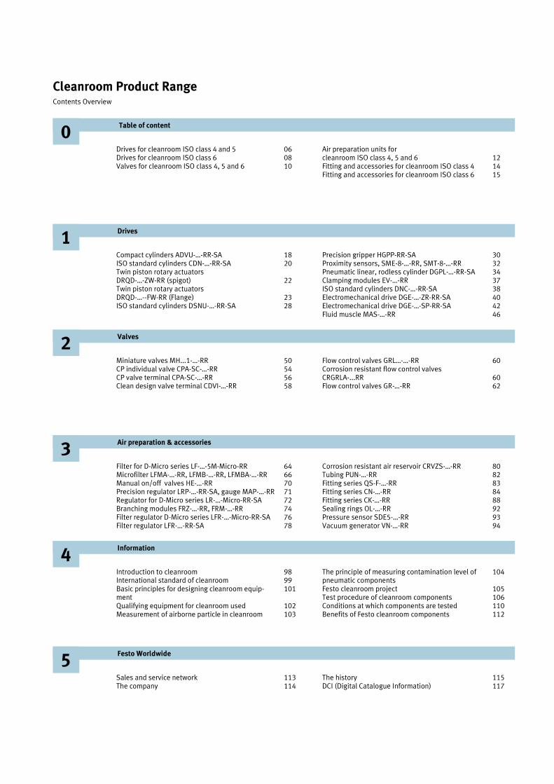
0Table of content
Drives for cleanroom ISO class 4 and 5 Drives for cleanroom ISO class 6 Valves for cleanroom ISO class 4, 5 and 6
Air preparation units for cleanroom ISO class 4, 5 and 6 Fitting and accessories for cleanroom ISO class 4 Fitting and accessories for cleanroom ISO class 6
06 08 10
12 1415
115 117

Table of content
Drives
Drives for cleanroom ISO Class 4 and 5(FS209E class 10 and class 100)
Type Function Piston Ø (mm) Stroke (mm) Variant Cleanroom Class Page
ADVU-…-RR-SA Compact cylinder
16, 20, 25 32, 40
5...100 5...200
P-A: Internal rod thread A-P-A: Exter-nal rod thread
ISO 4 (FS209E class 10)
18
CDN-…-RR-SA ISO stan-dard, double acting cylin-der
32, 40, 50 10...500 PPV: Adj. cushioning PPV-A: Adj. cushioning and mag-netic sensing
ISO 4 (FS209E class 10)
20
DRQD-…-ZW-RR DRQD-…-FW-RR
Rotary actua-tor with spigot or flange
16, 20, 25, 32 90°, 180, 360°
PPV: Adj. cushioning YSRJ: Hy-draulic cush-ioning AL, AR: air on left or right
ISO 4 (FS209E class 10)
22 23
DSNU-…-RR-SA ISO stan-dard, double acting cylin-der
8, 10 12, 16 20 25
10...100 10...200 10...320 10...500
P-A: Damp-ing and mag-netic sensing PPV-A: Adj. cushioning and mag-netic sensing
ISO 4 (FS209E class 10)
28
HGPP-…-RR-SA Precision parallel grip-per
12 16 20
2.5 5.0 7.5
- ISO 4 (FS209E class 10)
30
SME-8-…-RR SMT-8-…-RR
Proximity sensor for cylinders with 8 mm slot
- - Contact type Electronic type With cable With plug
ISO 4 (FS209E class 10)
32
DGPL-…-KF-RR-SA
Double act-ing linear, rodless cylin-der
25, 32, 40 10...1000 KF: With recirculating ball bearing slide
ISO 4 or 5 (FS209E class 10 or 100)
34
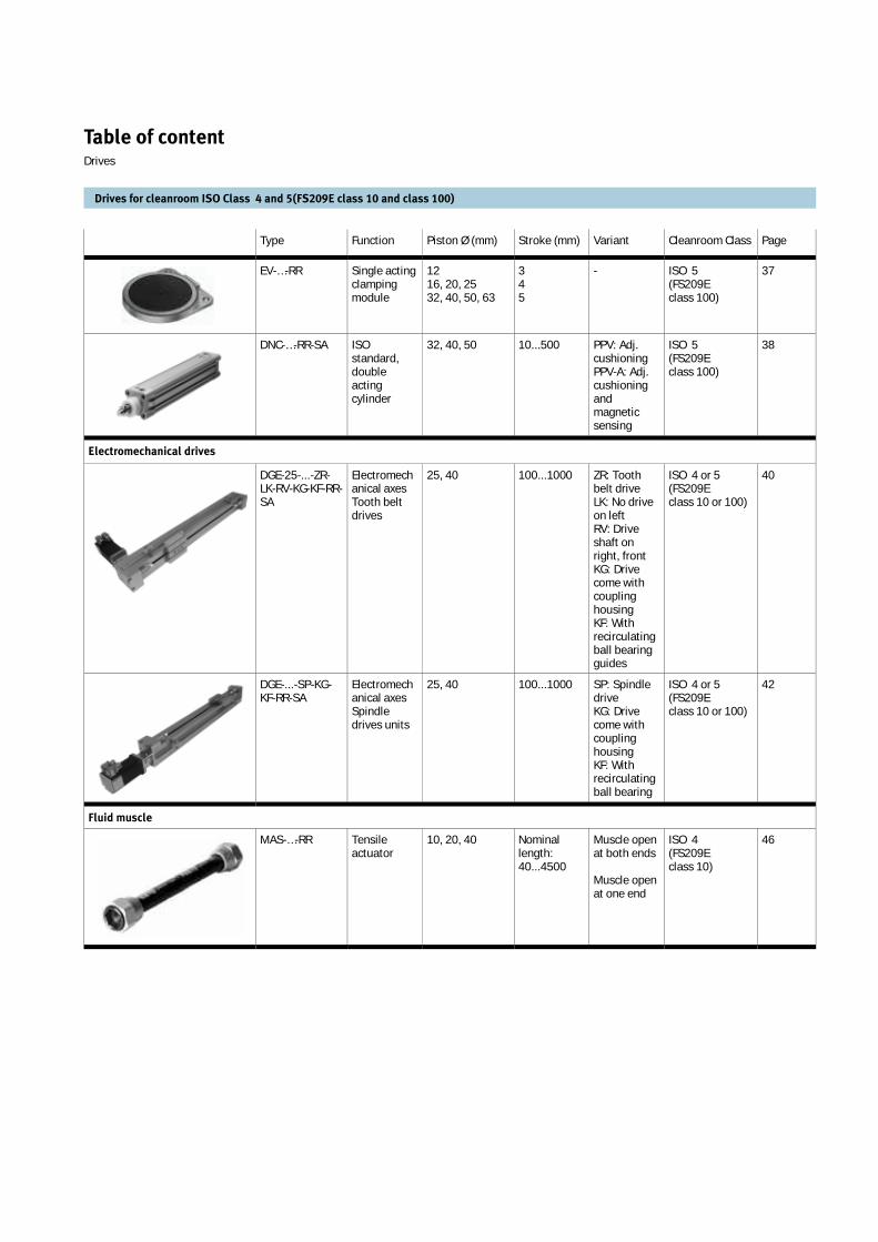
Table of content Drives
Drives for cleanroom ISO Class 4 and 5(FS209E class 10 and class 100)
Type Function Piston Ø (mm) Stroke (mm) Variant Cleanroom Class Page
EV-…-RR Single acting clamping module
12 16, 20, 25 32, 40, 50, 63
345
- ISO 5 (FS209E class 100)
37
DNC-…-RR-SA ISO standard, double acting cylinder
32, 40, 50 10...500 PPV: Adj. cushioning PPV-A: Adj. cushioning and magnetic sensing
ISO 5 (FS209E class 100)
38
Electromechanical drives
DGE-25-...-ZR-LK-RV-KG-KF-RR-SA
Electromechanical axes Tooth belt drives
25, 40 100...1000 ZR: Tooth belt drive LK: No drive on left RV: Drive shaft on right, front KG: Drive come with coupling housing KF: With recirculating ball bearing guides
ISO 4 or 5 (FS209E class 10 or 100)
40
DGE-...-SP-KG-KF-RR-SA
Electromechanical axes Spindle drives units
25, 40 100...1000 SP: Spindle drive KG: Drive come with coupling housing KF: With recirculating ball bearing
ISO 4 or 5 (FS209E class 10 or 100)
42
Fluid muscle
MAS-…-RR Tensile actuator
10, 20, 40 Nominal length: 40...4500
Muscle open at both ends
Muscle open at one end
ISO 4 (FS209E class 10)
46

Table of content Drives
Drives for cleanroom ISO Class 6 (FS209E class 1000)
Type Function Piston Ø (mm) Stroke (mm) Variant Cleanroom class Page
ADVC Compact cylinder
6, 10, 12, 16, 20, 25, 32
5...25 P-A: External rod thread A-P-A: Inter-nal rod thread
ISO 6 (FS209E class 1000)
Refer to DCI on page 117
ADVU Compact cylinder
16, 20, 25 32, 40, 50
5...100 5...200
P-A: External rod thread A-P-A: Inter-nal rod thread
ISO 6 (FS209E class 1000)
Refer to DCI on page 117
CDN ISO stan-dard, double acting cylin-der
32, 40, 50 10...500 PPV: Adj. cushioning PPV-A: Adj. cushioning and mag-netic sensing
ISO 6 (FS209E class 1000)
Refer to DCI on page 117
DFC Compact guided drive
6, 10 5...30 KF: With recirculating ball bearing guide
ISO 6 (FS209E class 1000)
Refer to DCI on page 117
DFM Guided drive 12, 16, 20, 25, 32
10...200 KF: With recirculating ball bearing guide
ISO 6 (FS209E class 1000)
Refer to DCI on page 117
DMM Multimount cylinder
10, 16, 20, 25, 32
5...50 P-A: With damping and magnetic sensing
ISO 6 (FS209E class 1000)
Refer to DCI on page 117
DNC ISO stan-dard, double acting cylin-der
32, 40, 50 10...500 PPV: Adj. cushioning PPV-A: Adj. cushioning and mag-netic sensing
ISO 6 (FS209E class 1000)
Refer to DCI on page 117
DSNU ISO stan-dard, double acting cylin-der
8, 10 12, 16 20 25
10...100 10...200 10...320 10...500
P-A: Damp-ing and mag-netic sensing PPV-A: Adj. cushioning and mag-netic sensing
ISO 6 (FS209E class 1000)
Refer to DCI on page 117

Table of content Drives
Drives for cleanroom ISO Class 6 (FS209E class 1000)
Type Function Piston Ø (mm) Stroke (mm) Variant Cleanroom class Page
DRQD Rotary actua-tor
6, 8, 12, 16, 20, 25, 32
90°, 180, 360°
PPV: Adj. cushioning YSRJ: Hy-draulic cush-ioningAL, AR: air on left or right
ISO 6 (FS209E class 1000)
Refer to DCI on page 117
DSM Swivel actua-tor
12, 16, 16, 25, 32, 40
0...270° Standard: With spigot shaft FW: With flanged shaft
ISO 6 (FS209E class 1000)
Refer to DCI on page 117
EV Single acting clamping module
12, 16, 20, 25, 32, 40, 50, 63
3, 4, 5 - ISO 6 (FS209E class 1000)
Refer to DCI on page 117
SLG Mini slide rodless
12 100...700 P-A: With damping and magnetic sensing
ISO 6 (FS209E class 1000)
Refer to DCI on page 117
SLF Mini slide double act-ing
10 10...50 YSR: Hydrau-lic shock absorbers in both ends
ISO 6 (FS209E class 1000)
Refer to DCI on page 117
SLS Mini slide double act-ing
10 5...30 P-A: With damping and magnetic sensing
ISO 6 (FS209E class 1000)
Refer to DCI on page 117
SLT Mini slide double act-ing
6, 10, 16, 20, 25 10...200 P-A: With damping and magnetic sensing P-A-CC: With shock ab-sorber
ISO 6 (FS209E class 1000)
Refer to DCI on page 117
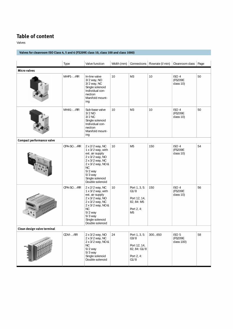
Type Valve function Width (mm) Connections Flowrate (l/min) Cleanroom class Page
Micro valves
MHP1-…-RR In-line valve 3/2 way, NO 3/2 way, NC Single solenoid Individual con-nection Manifold mount-ing
10 M3 10 ISO 4 (FS209E class 10)
50
MHA1-…-RR Sub-base valve 3/2 NO 3/2 NC Single solenoid Individual con-nection Manifold mount-ing
10 M3 10 ISO 4 (FS209E class 10)
50
Compact performance valve
CPA-SC-…-RR 2 x 2/2 way, NC 1 x 3/2 way, with ext. air supply 2 x 3/2 way, NO 2 x 3/2 way, NC 2 x 3/2 way, NO & NC 5/2 way 5/3 way Single solenoid Double solenoid
10 M5 150 ISO 4 (FS209E class 10)
54
CPA-SC-…-RR 2 x 2/2 way, NC 1 x 3/2 way, with ext. air supply 2 x 3/2 way, NO 2 x 3/2 way, NC 2 x 3/2 way, NO & NC 5/2 way 5/3 way Single solenoid Double solenoid
10 Port 1, 3, 5: G1/8
Port 12, 14, 82, 84: M5
Port 2, 4: M5
150 ISO 4 (FS209E class 10)
56
Clean design valve terminal
CDVI-…-RR 2 x 3/2 way, NO 2 x 3/2 way, NC 2 x 3/2 way, NO & NC 5/2 way 5/3 way Single solenoid Double solenoid
24 Port 1, 3, 5: G3/8
Port 12, 14, 82, 84: G1/8
Port 2, 4: G1/8
300...650 ISO 5 (FS209E class 100)
58
Table of content Valves
Valves for cleanroom ISO Class 4, 5 and 6 (FS209E class 10, class 100 and class 1000)

Type Valve function Width (mm) Connections Flowrate (l/min) Cleanroom class Page
Compact performance valve
CPV-SC 2 x 3/2 way, NO 2 x 3/2 way, NC 2 x 3/2 way, NO & NC 5/2 way 5/3 way Single solenoid Double solenoid
10 M5 150...170 ISO 6 (FS209E class 1000)
Refer to DCI on page117
GRLA-…-RR GRLZ-…-RR GRLO-…-RR
Throttle out Throttle in Without check valve
- M3 M5 G1/8 G1/4 PK-3 PK-4 PK-6
0...750 ISO 4 (FS209E class 10)
60
CRGRLA-…-RR Throttle out - M3 M5 G1/8 G1/4
0...610 ISO 4 (FS209E class 10)
60
GR-…-RR GRA-…-RR
In-line - M3 M5 G1/8 G1/4
0...420 ISO 4 (FS209E class 10)
62
Flow control valve
CPE 3/2 way 5/2 way 5/3 way Single solenoid Double solenoid Individual connection Manifold mounting
Micro 10 Mini 14
M5 G1/8
180...800 ISO 6 (FS209E class 1000)
Refer to DCI on page117
CPV10 2 x 2/2 way, NC 2 x 2/2 way, NO & NC 2 x 3/2 way, NO 2 x 3/2 way, NC 2 x 3/2 way, NO & NC 5/2 way 5/3 way Single solenoid Double solenoid Fast switching valve Vacuum generator
10 Port 1, 11: G1/8
Port 3, 5: G3/8
Port 12, 14, 82, 84: M5
Port 2, 4: M7
400 ISO 6 (FS209E class 1000)
Refer to DCI on page117
Table of content Valves
Valves for cleanroom ISO Class 4, 5 and 6 (FS209E class 10, class 100 and class 1000)
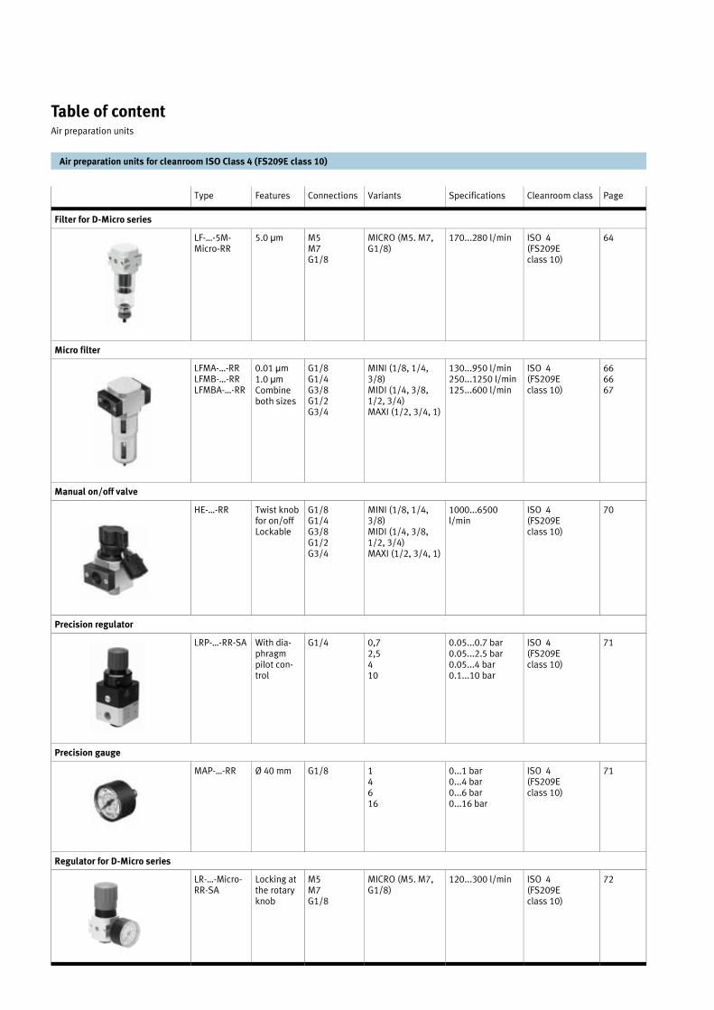
Table of content Air preparation units
Air preparation units for cleanroom ISO Class 4 (FS209E class 10)
Type Features Connections Variants Specifications Cleanroom class Page
Filter for D-Micro series
LF-…-5M-Micro-RR
5.0 µm M5 M7 G1/8
MICRO (M5. M7, G1/8)
170...280 l/min ISO 4 (FS209E class 10)
64
Micro filter
LFMA-…-RR LFMB-…-RR LFMBA-…-RR
0.01 µm1.0 µmCombine both sizes
G1/8 G1/4 G3/8 G1/2 G3/4
MINI (1/8, 1/4, 3/8) MIDI (1/4, 3/8, 1/2, 3/4) MAXI (1/2, 3/4, 1)
130...950 l/min 250...1250 l/min 125...600 l/min
ISO 4 (FS209E class 10)
66 66 67
Manual on/off valve
HE-…-RR Twist knob for on/off Lockable
G1/8 G1/4 G3/8 G1/2 G3/4
MINI (1/8, 1/4, 3/8) MIDI (1/4, 3/8, 1/2, 3/4) MAXI (1/2, 3/4, 1)
1000...6500 l/min
ISO 4 (FS209E class 10)
70
Precision regulator
LRP-…-RR-SA With dia-phragm pilot con-trol
G1/4 0,7 2,5 410
0.05...0.7 bar 0.05...2.5 bar 0.05...4 bar 0.1...10 bar
ISO 4 (FS209E class 10)
71
Precision gauge
MAP-…-RR Ø 40 mm G1/8 14616
0...1 bar 0...4 bar 0...6 bar 0...16 bar
ISO 4 (FS209E class 10)
71
Regulator for D-Micro series
LR-…-Micro-RR-SA
Locking at the rotary knob
M5 M7 G1/8
MICRO (M5. M7, G1/8)
120...300 l/min ISO 4 (FS209E class 10)
72
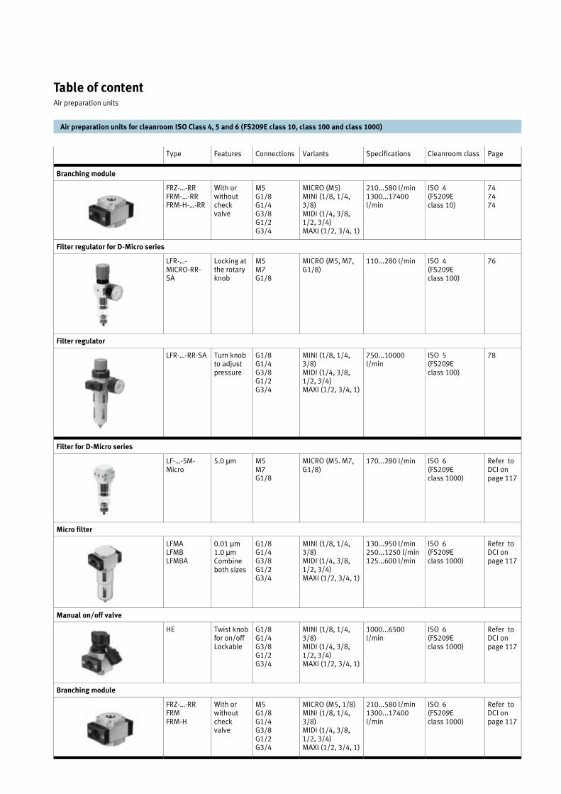
Table of content Air preparation units
Air preparation units for cleanroom ISO Class 4, 5 and 6 (FS209E class 10, class 100 and class 1000)
Type Features Connections Variants Specifications Cleanroom class Page
Branching module
FRZ-…-RR FRM-…-RR FRM-H-…-RR
With or without check valve
M5 G1/8 G1/4 G3/8 G1/2 G3/4
MICRO (M5) MINI (1/8, 1/4, 3/8) MIDI (1/4, 3/8, 1/2, 3/4) MAXI (1/2, 3/4, 1)
210...580 l/min 1300...17400 l/min
ISO 4 (FS209E class 10)
74 74 74
LFR-…-MICRO-RR-SA
Locking at the rotary knob
M5 M7 G1/8
MICRO (M5, M7, G1/8)
110...280 l/min ISO 4 (FS209E class 100)
76
Filter regulator
LFR-…-RR-SA Turn knob to adjust pressure
G1/8 G1/4 G3/8 G1/2 G3/4
MINI (1/8, 1/4, 3/8) MIDI (1/4, 3/8, 1/2, 3/4) MAXI (1/2, 3/4, 1)
750...10000 l/min
ISO 5 (FS209E class 100)
78
Filter for D-Micro series
LF-…-5M-Micro
5.0 µm M5 M7 G1/8
MICRO (M5. M7, G1/8)
170...280 l/min ISO 6 (FS209E class 1000)
Refer to DCI on page 117
Micro filter
LFMALFMBLFMBA
0.01 µm1.0 µmCombine both sizes
G1/8 G1/4 G3/8 G1/2 G3/4
MINI (1/8, 1/4, 3/8) MIDI (1/4, 3/8, 1/2, 3/4) MAXI (1/2, 3/4, 1)
130...950 l/min 250...1250 l/min 125...600 l/min
ISO 6 (FS209E class 1000)
Refer to DCI on page 117
Manual on/off valve
HE Twist knob for on/off Lockable
G1/8 G1/4 G3/8 G1/2 G3/4
MINI (1/8, 1/4, 3/8) MIDI (1/4, 3/8, 1/2, 3/4) MAXI (1/2, 3/4, 1)
1000...6500 l/min
ISO 6 (FS209E class 1000)
Refer to DCI on page 117
Branching module
FRZ-…-RR FRM FRM-H
With or without check valve
M5 G1/8 G1/4 G3/8 G1/2 G3/4
MICRO (M5, 1/8) MINI (1/8, 1/4, 3/8) MIDI (1/4, 3/8, 1/2, 3/4) MAXI (1/2, 3/4, 1)
210...580 l/min 1300...17400 l/min
ISO 6 (FS209E class 1000)
Refer to DCI on page 117
Filter regulator for D-Micro series
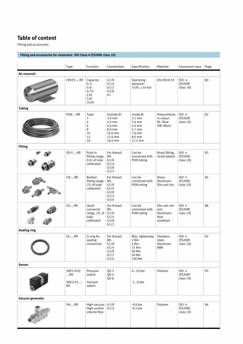
Table of content Fitting and accessories
Fitting and accessories for cleanroom ISO Class 4 (FS209E class 10)
Type Function Connections Specification Material Cleanroom class Page
Air reservoir
CRVZS-…-RR Capacity: 0.1l 0.4l 0.75l 2.0l 5.0l 10.0l
G1/8 G1/4 G1/2 G3/8 G1
Operating pressure: -0.95…+16 bar
X5CrNi18 10 ISO 4 (FS209E class 10)
80
Tubing
PUN-…-RR Type: 346810 12 16
Outside Ø: 3.0 mm 4.0 mm 6.0 mm 8.0 mm 10.0 mm 12.0 mm 16.0 mm
Inside Ø: 2.1 mm 2.6 mm 4.0 mm 5.7 mm 7.0 mm 8.0 mm 11.2 mm
Polyurethane in colour: BL: Blue SW: Black
ISO 4 (FS209E class 10)
82
Fitting
QS-F-…-RR Push in fitting range, O.D. of tube calibrated
For thread: M5 G1/8 G1/4 G3/8 G1/2
Can be connected with PUN tubing
Brass fitting, nickel plated.
ISO 4 (FS209E class 10)
83
CN-…-RR Barbed fitting range, I.D. of tube calibrated
For thread: M5 G1/8 G1/4 G3/8 G1/2 G3/4
Can be connected with PUN tubing
Brass Aluminum Die-cast zinc
ISO 4 (FS209E class 10)
84
CK-…-RR Quick connector range, I.D. of tube calibrated
For thread: M5 G1/8 G1/4 G3/8 G1/2
Can be connected with PUN tubing
Die-cast zinc and Aluminum, blue anodised
ISO 4 (FS209E class 10)
88
Sealing ring
OL-…-RR O-ring for sealing connection
For thread: M5 G1/8 G1/4 G3/8 G1/2 G3/4
Max. tightening: 2 Nm 4 Nm 11 Nm 40 Nm 50 Nm 100 Nm
Stainless steel Aluminum NBR
ISO 4 (FS209E class 10)
92
Sensor
SDE5-D10-…-RR
SDE5-V1-…-RR
Pressure switch
Vacuum switch
QS-3 QS-4 QS-6
0...10 bar
-1...0 bar
Polymer ISO 4 (FS209E class 10)
93
Vacuum generator
VN-…-RR High vacuum High suction volume flow
G1/8 G1/4
-0.8 bar -0.5 bar
Polymer ISO 4 (FS209E class 10)
94

Table of content Fitting and accessories
Fitting and accessories for cleanroom ISO 6 (FS209E class 1000)
Type Function Connections Specification Material Cleanroom class Page
Air reservoir
CRVZS-… Capacity: 0.1l 0.4l 0.75l 2.0l 5.0l 10.0l
G1/8 G1/4 G1/2 G3/8 G1
Operating pressure: -0.95…+16 bar
X5CrNi18 10 ISO 6 (FS209E class 1000)
Refer to DCI on page 117
Tubing
PUN-… Type: 346810 12 16
Outside Ø: 3.0 mm 4.0 mm 6.0 mm 8.0 mm 10.0 mm 12.0 mm 16.0 mm
Inside Ø: 2.1 mm 2.6 mm 4.0 mm 5.7 mm 7.0 mm 8.0 mm 11.2 mm
Polyurethane in colour: BL: Blue SW: Black
ISO 6 (FS209E class 1000)
Refer to DCI on page 117
Fitting
QS-F-… Push in fitting range, O.D. of tube calibrated
For thread: M5 G1/8 G1/4 G3/8 G1/2
Can be connected with PUN tubing
Brass fitting, nickel plated.
ISO 6 (FS209E class 1000)
Refer to DCI on page 117
CN-… Barbed fitting range, I.D. of tube calibrated
For thread: M5 G1/8 G1/4 G3/8 G1/2 G3/4
Can be connected with PUN tubing
Brass Aluminum Die-cast zinc
ISO 6 (FS209E class 1000)
Refer to DCI on page 117
CK-… Quick connector range, I.D. of tube calibrated
For thread: M5 G1/8 G1/4 G3/8 G1/2
Can be connected with PUN tubing
Die-cast zinc and Aluminum, blue anodised
ISO 6 (FS209E class 1000)
Refer to DCI on page 117
Sealing ring
OL-… O-ring for sealing connection
For thread: M5 G1/8 G1/4 G3/8 G1/2 G3/4
Max. tightening: 2 Nm 4 Nm 11 Nm 40 Nm 50 Nm 100 Nm
Stainless steel Aluminum NBR
ISO 6 (FS209E class 1000)
Refer to DCI on page 117
Sensor
SDE5-D10-…
SDE5-V1-…
Pressure switch
Vacuum switch
QS-3 QS-4 QS-6
0...10 bar
-1...0 bar
Polymer ISO 6 (FS209E class 1000)
Refer to DCI on page 117
Vacuum generator
VN-… High vacuum High suction volume flow
G1/8 G1/4
-0.8 bar -0.5 bar
Polymer ISO 6 (FS209E class 1000)
Refer to DCI on page 117


Drives

Double acting cylinder with flexi-
ble cushioning rings in the end
positions and contact-less sens-
ing. The cylinder come with inter-
nal piston rod thread.
ADVU-…-P-A-RR-SA
Double acting cylinder with flexi-
ble cushioning rings in the end
positions and contact-less sens-
ing. The cylinder come with exter-
nal piston rod thread.
ADVU-…-A-P-A-RR-SA
Proximity sensor for fitting in 8
mm slot
SME-8.../SMT-8-...
Compact cylinders ADVU permit
space saving of 50% in com-
parison with standard cylinder
of similar power while offering
the same force
As with all standard drives, the
proximity sensor SME-8 can be
used in the profile slot in the
compact cylinder
Order example:
Order no: 15024226
Type: ADVU-25-80-P-A-RR-SA
Double acting cylinder, diame-
ter 25 mm, stroke 80 mm with
internal piston rod thread.
Mounting options
Swivel flange
Ø 16, 20, 25, 32, 40
SUA-…
Flange mounting
Ø 16, 20, 25, 32, 40
FUA-…
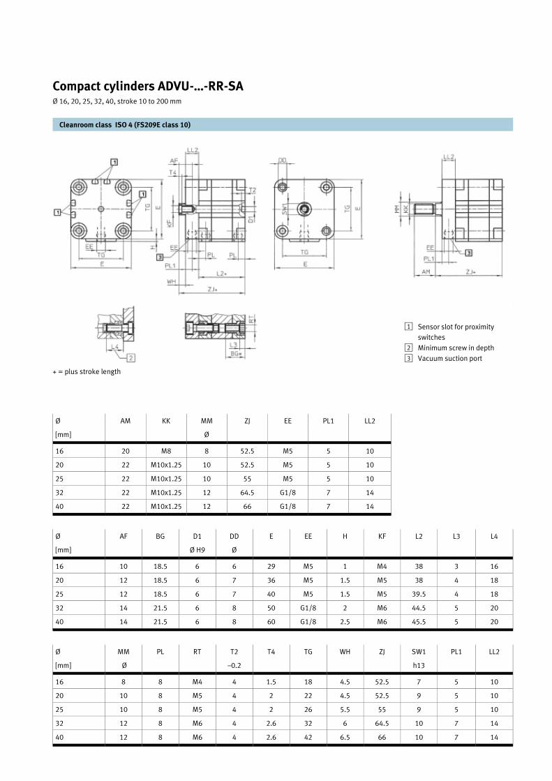
Cleanroom class ISO 4 (FS209E class 10)
Compact cylinders ADVU-…-RR-SA Ø 16, 20, 25, 32, 40, stroke 10 to 200 mm
Type [Internal rod thread]
Part No. Type [external rod thread]
Part No. Piston Ø [mm]
Stroke [mm]
Thrust at 6 bar [N]
Return force [N]
Connection
ADVU-16-…-P-A-RR-SA 15024223 ADVU-16-…-A-P-A-RR-SA 15024230 16 1 … 100 121 90 M5
ADVU-20-…-P-A-RR-SA 15024225 ADVU-20-…-A-P-A-RR-SA 15024231 20 1 … 100 188 141 M5
ADVU-25-…-P-A-RR-SA 15024226 ADVU-25-…-A-P-A-RR-SA 15024233 25 1 … 100 295 247 M5
ADVU-32-…-P-A-RR-SA 15024227 ADVU-32-…-A-P-A-RR-SA 15024234 32 1 … 200 483 415 G1/8
ADVU-40-…-P-A-RR-SA 15024228 ADVU-40-…-A-P-A-RR-SA 15024235 40 1 … 200 754 686 G1/8
Technical data
Medium Compressed air, filtered (lubricated or unlubricated)
Max. operating pressure 10 bar
Temperature range –20 ... +80 °C (note operating range of proximity sen-sor)
Cylinder barrel and cover Anodised aluminium
Piston rod Stainless steel
Seals Polyurethane
Materials
Cleanroom class ISO 4 (FS209E class 10)
Compact cylinders ADVU-…-RR-SA Ø 16, 20, 25, 32, 40, stroke 10 to 200 mm
Ø AF BG D1 DD E EE H KF L2 L3 L4
[mm] Ø H9 Ø
16 10 18.5 6 6 29 M5 1 M4 38 3 16
20 12 18.5 6 7 36 M5 1.5 M5 38 4 18
25 12 18.5 6 7 40 M5 1.5 M5 39.5 4 18
32 14 21.5 6 8 50 G1/8 2 M6 44.5 5 20
40 14 21.5 6 8 60 G1/8 2.5 M6 45.5 5 20
Ø MM PL RT T2 T4 TG WH ZJ SW1 PL1 LL2
[mm] Ø –0.2 h13
16 8 8 M4 4 1.5 18 4.5 52.5 7 5 10
20 10 8 M5 4 2 22 4.5 52.5 9 5 10
25 10 8 M5 4 2 26 5.5 55 9 5 10
32 12 8 M6 4 2.6 32 6 64.5 10 7 14
40 12 8 M6 4 2.6 42 6.5 66 10 7 14
Ø AM KK MM ZJ EE PL1 LL2
[mm] Ø
16 20 M8 8 52.5 M5 5 10
20 22 M10x1.25 10 52.5 M5 5 10
25 22 M10x1.25 10 55 M5 5 10
32 22 M10x1.25 12 64.5 G1/8 7 14
40 22 M10x1.25 12 66 G1/8 7 14
Sensor slot for proximity
switches
Minimum screw in depth
Vacuum suction port
1
2
3
+ = plus stroke length

Cylinder with adjustable end
cushioning, without sensor at the
end
CDN-…-PPV –RR-SA
Cylinder with adjustable end
cushioning and sensor at the two
ends
CDN-…-PPV –A-RR-SA
Order example:
Order no: 15024283
Type: CDN-32-200-PPV-A-RR-SA
Double acting cylinder, diameter
32 mm, stroke 200 mm with ad-
justable cushioning and sensor at
the ends . Sensor cables are not
included in the scope of delivery
Accessories
Straight connector cable
SIM-K-GD-…-CDN-RR
Swivel flange
Ø 32, 40, 50
SNCB-…
Trunnion flange
Ø 32, 40, 50
CRZNG-…
Easy to clean, double-acting
cylinders suitable for the most
demanding of anti-corrosion
and special design require-
ments.
Proximity sensors for the end
positions can be integrated in
the housing.
– Dimensions and connection
sizes as per ISO 6431, DIN
ISO 6431, VDMA 24 562, NF
E 49 003.1, and UNI 10 290
– Corrosion and acid resistant
– Adjustable end-position
cushioning at both ends
– Contact-less end-position
sensing with electronic prox-
imity sensor or reed contact
– End-position sensing on both
sides
Angled connector cable
SIM-K-WD-…-CDN-RR
Mounting options
Foot mounting
Ø 32, 40, 50
CRHNA-…
Flange mounting
Ø 32, 40, 50
CRFNG-…
Cleanroom class ISO 4 (FS209E class 10)
Standard cylinders CDN-…-RR-SA Ø 32, 40, 50, stroke 10 to 500 mm
Type Part No. Type Part No. Piston Ø Stroke Thrust at 6 bar
Return force
Cushioning length
Connection
[without magnet] [with magnet] [mm] [N] [N] [mm]
CDN-32-…-PPV-RR-SA 15024278 CDN-32-…-PPV-A-RR-SA 15023418 32 10 …500 483 415 20 G1/8
CDN-40-…-PPV-RR-SA 15024280 CDN-40-…-PPV-A-RR-SA 15024285 40 10 …500 754 633 20 G1/4
CDN-50-…-PPV-RR-SA 15024281 CDN-50-…-PPV-A-RR-SA 15024287 50 10 …500 1178 990 22 G1/4
M8 plug with cable [m] Type Part No.
Straight 2.5 SIM-K-GD-2,5-CDN-RR 15025008
5 SIM-K-GD-5-CDN-RR 15025009
Angled 2.5 SIM-K-WD-2,5-CDN-RR 15025010
5 SIM-K-WD-5-CDN-RR 15025011

+ = plus stroke length
Cleanroom class ISO 4 (FS209E class 10)
Standard cylinders CDN-…-RR-SA Ø 32, 40, 50, stroke 10 to 500 mm
Ø AM B BG E EE EE1 J1 J2 J3 KK L1 L2 LL1 LL2
[mm] Ø d11
32 22 30 16 50 G1/8 G1/8 6.2 6.3 5.3 M10x1.25 18.5 94 ±0.4 22 18
40 24 35 16 58 G1/4 G1/8 9.9 8 6 M12x1.25 21 104.8 ±0.4 26.5 20
50 32 40 17 70 G1/4 G1/8 9.7 10.4 8.5 M16x1.50 27 105.9 ±0.5 34 26
Ø L3 L4 L7 MM PL PL1 RT TG VA VD WH ZJ SW1 SW2 SW3
[mm] Ø f8
32 19.8 38 4.1 12 13.8 8 M6 32.5 4 4 26.7 ±1 120.7 10 17 6
40 24.3 42 1.9 16 15.5 8 M6 38 4 6.5 30.8 ±1 135.6 13 19 6
50 24.3 47 1.9 20 14 8 M8 46.5 4 8 38.1 ±1.2 144 17 24 8
Socket head screws with
female threads for mounting
attachments
Regulating screw for adjust-
able end-position cushioning
1
2
Miniature plug connector, 3-
pin, for integrated proximity
sensors SME/SMT; suitable
for plug socket with cable
SIM-K-...-CDN
Vacuum suction port
3
4
Accessories
Proximity sensor for fitting in 8
mm slot
SME-8.../SMT-8-...
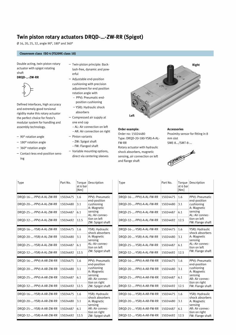
Double acting, twin piston rotary
actuator with spigot rotating
shaft
DRQD-…-ZW-RR
Defined interfaces, high accuracy
and extremely good torsional
rigidity make this rotary actuator
the perfect choice for Festo’s
modular system for handling and
assembly technology.
– 90° rotation angle
– 180° rotation angle
– 360° rotation angle
– Contact-less end-position sens-
ing
– Twin-piston principle: Back-
lash-free, dynamic and pow-
erful
– Adjustable end-position
cushioning with precision
adjustment for end position
rotation angle with
– PPVJ: Pneumatic end-
position cushioning
– YSRJ: Hydraulic shock
absorbers
– Compressed air supply at
one end cap
– AL: Air connection on left
– AR: Air connection on right
– Pinion variants
– ZW: Spigot shaft
– FW: Flanged shaft
– Variable mounting options,
direct via centering sleeves
Order example:
Order no: 15024480
Type: DRQD-20-180-YSRJ-A-AL-
FW-RR
Rotary actuator with hydraulic
shock absorbers, magnetic
sensing, air connection on left
and flange shaft
Cleanroom class ISO 4 (FS209E class 10)
Twin piston rotary actuators DRQD-…-ZW-RR (Spigot) Ø 16, 20, 25, 32, angle 90°, 180° and 360°
Left
Right
Type Part No. Torque at 6 bar [Nm]
Description
DRQD-16-...-PPVJ-A-AL-ZW-RR 15024475 1.6 PPVJ: Pneumatic end-position cushioning A: Magnetic sensing AL: Air connec-tion on left ZW: Spigot shaft
DRQD-20-...-PPVJ-A-AL-ZW-RR 15024480 3.1
DRQD-25-...-PPVJ-A-AL-ZW-RR 15024487 6.1
DRQD-32-...-PPVJ-A-AL-ZW-RR 15024492 12.5
DRQD-16-...-YSRJ-A-AL-ZW-RR 15024475 1.6 YSRJ: Hydraulic shock absorbers A: Magnetic sensing AL: Air connec-tion on left ZW: Spigot shaft
DRQD-20-...-YSRJ-A-AL-ZW-RR 15024480 3.1
DRQD-25-...-YSRJ-A-AL-ZW-RR 15024487 6.1
DRQD-32-...-YSRJ-A-AL-ZW-RR 15024492 12.5
DRQD-16-...-PPVJ-A-AR-ZW-RR 15024475 1.6 PPVJ: Pneumatic end-position cushioning A: Magnetic sensing AR: Air connec-tion on right ZW: Spigot shaft
DRQD-20-...-PPVJ-A-AR-ZW-RR 15024480 3.1
DRQD-25-...-PPVJ-A-AR-ZW-RR 15024487 6.1
DRQD-32-...-PPVJ-A-AR-ZW-RR 15024492 12.5
DRQD-16-...-YSRJ-A-AR-ZW-RR 15024475 1.6 YSRJ: Hydraulic shock absorbers A: Magnetic sensing AR: Air connec-tion on right ZW: Spigot shaft
DRQD-20-...-YSRJ-A-AR-ZW-RR 15024480 3.1
DRQD-25-...-YSRJ-A-AR-ZW-RR 15024487 6.1
DRQD-32-...-YSRJ-A-AR-ZW-RR 15024492 12.5
Type Part No. Torque at 6 bar [Nm]
Description
DRQD-16-...-PPVJ-A-AL-FW-RR 15024475 1.6 PPVJ: Pneumatic end-position cushioning A: Magnetic sensing AL: Air connec-tion on left FW: Flange shaft
DRQD-20-...-PPVJ-A-AL-FW-RR 15024480 3.1
DRQD-25-...-PPVJ-A-AL-FW-RR 15024487 6.1
DRQD-32-...-PPVJ-A-AL-FW-RR 15024492 12.5
DRQD-16-...-YSRJ-A-AL-FW-RR 15024475 1.6 YSRJ: Hydraulic shock absorbers A: Magnetic sensing AL: Air connec-tion on left FW: Flange shaft
DRQD-20-...-YSRJ-A-AL-FW-RR 15024480 3.1
DRQD-25-...-YSRJ-A-AL-FW-RR 15024487 6.1
DRQD-32-...-YSRJ-A-AL-FW-RR 15024492 12.5
DRQD-16-...-PPVJ-A-AR-FW-RR 15024475 1.6 PPVJ: Pneumatic end-position cushioning A: Magnetic sensing AR: Air connec-tion on right FW: Flange shaft
DRQD-20-...-PPVJ-A-AR-FW-RR 15024480 3.1
DRQD-25-...-PPVJ-A-AR-FW-RR 15024487 6.1
DRQD-32-...-PPVJ-A-AR-FW-RR 15024492 12.5
DRQD-16-...-YSRJ-A-AR-FW-RR 15024475 1.6 YSRJ: Hydraulic shock absorbers A: Magnetic sensing AR: Air connec-tion on right FW: Flange shaft
DRQD-20-...-YSRJ-A-AR-FW-RR 15024480 3.1
DRQD-25-...-YSRJ-A-AR-FW-RR 15024487 6.1
DRQD-32-...-YSRJ-A-AR-FW-RR 15024492 12.5

Double acting, twin piston rotary
actuator with rotating flange
DRQD-…-FW-RR
Cleanroom class ISO 4 (FS209E class 10)
Twin piston rotary actuators DRQD-…-FW-RR (Flange) Ø 16, 20, 25, 32, angle 90°, 180° and 360°
Technical data 16 20 25 32
Ø 16 mm 20 mm 25 mm 32 mm
Design Rotary drive system in accordance with the rack and pinion principle
Mounting position Any
Pneumatic connection M5 G1/8
Operating pressure range DRQD-...-PPVJ 1 ... 10 bar
DRQD-...-YSRJ
Max. permissible frequency (for completed cycle of motion)
DRQD-...-PPVJ 90 ° 4.0 Hz 3.0 Hz 2.0 Hz 1.2 Hz
180 ° 3.0 Hz 2.2 Hz 1.3 Hz 0.8 Hz
360 ° 1.5 Hz 1.2 Hz 0.8 Hz 0.5 Hz
DRQD-...-YSRJ* 90 ° 2.0 Hz 2.0 Hz 1.5 Hz 1.2 Hz
180 ° 1.8 Hz 1.8 Hz 1.5 Hz 1.2 Hz
360 ° 1.0 Hz 1.0 Hz 0.9 Hz 0.8 Hz
* At temperatures of less than 0 °C, a maximum frequency of 1 Hz always applies to all YSRJ models.
Max. permissible mass mo-ments of inertia on the drive shaft
DRQD-...-PPVJ 5 x 10p kgm² 10 x 10p kgm² 20 x 10p kgm² 40 x 10p kgm²
DRQD-...-YSRJ 300 x 10p kgm² 400 x 10p kgm² 700 x 10p kgm² 1500 x 10p kgm²
Rotation angle range min./max. DRQD-...-PPVJ Nominal rotation angle: -20° +6° (per end position)
DRQD-...-YSRJ
Repetition accuracy DRQD-... < 0.05°
Temperature range –10°…+60
Materials Spiral tubing Polyurethane
Cylinder barrel, slip disc Anodised aluminium
Cap, SD transfer plate
Gear rack X 5 CrNi 18 9, hardened, milled teeth
Pinion X 14 CrMoS 17, hardened, treated surfaces, stamped teeth
Piston seal Polyurethane
Screws Galvanised steel
O-rings BUNA-N
Threaded pin Galvanised steel
Centring sleeves X 8 CrNi 18 9
2 ... 10 bar

Cleanroom class ISO 4 (FS209E class 10)
Twin piston rotary actuators DRQD-…-ZW-RR (Spigot) Ø 16, 20, 25, 32, angle 90°, 180° and 360°
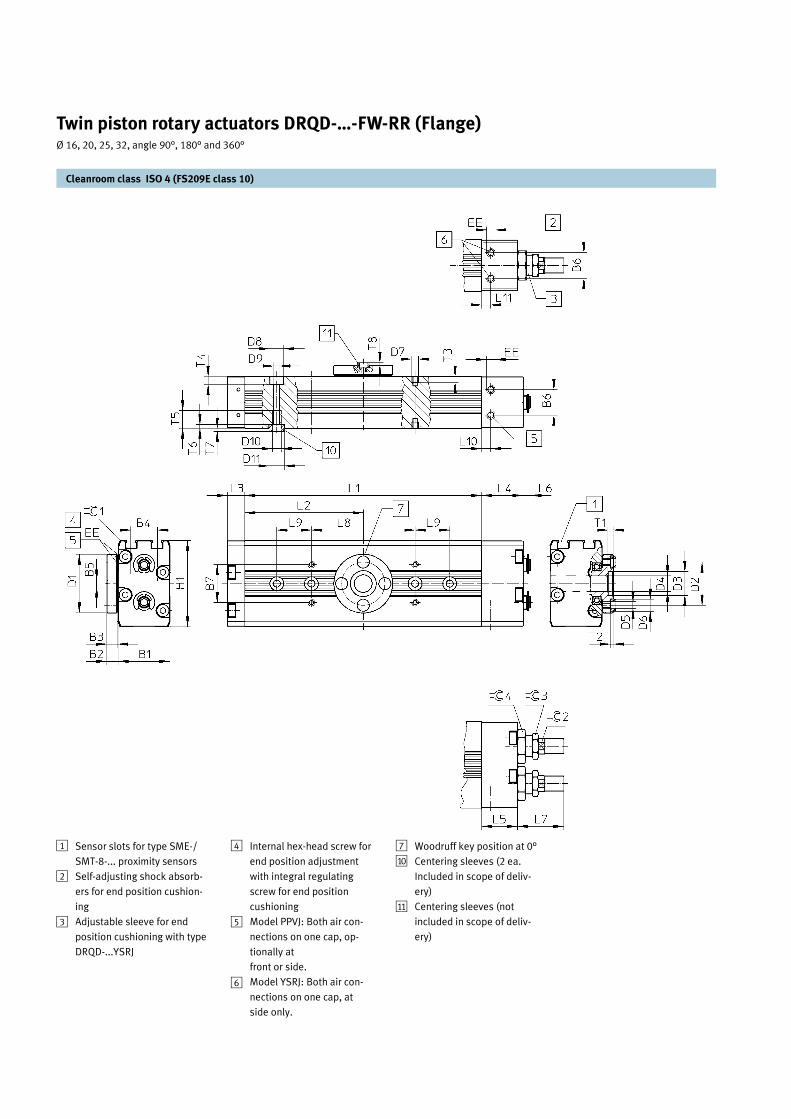
Sensor slots for type SME-/
SMT-8-... proximity sensors
Self-adjusting shock absorb-
ers for end position cushion-
ing
Adjustable sleeve for end
position cushioning with type
DRQD-...YSRJ
1
2
3
Internal hex-head screw for
end position adjustment
with integral regulating
screw for end position
cushioning
Model PPVJ: Both air con-
nections on one cap, op-
tionally at
front or side.
Model YSRJ: Both air con-
nections on one cap, at
side only.
Woodruff key position at 0°
Centering sleeves (2 ea.
Included in scope of deliv-
ery)
4
5
6
7
aJ

Cleanroom class ISO 4 (FS209E class 10)
Twin piston rotary actuators DRQD-…-RR (Spigot) Ø 16, 20, 25, 32, angle 90°, 180° and 360°
Type B1 B2 B3 B4 B5 B6 B7 B8 D1 Øg6
D2 Ø
D3 Ø
D4 D7 D8 Ø
H13
D9 Ø
D10 D11 Ø
H7
EE H1 H2 L1 L2
DRQD-16-90-... 30 25.5 23 17.8 4 14.8 22 23.5 10 12 18 M3 M4 8 4.2 M5 9 M5 50 11.2 71 35.5
DRQD-16-180-... 93 46.5
DRQD-16-360-... 137 68.5
DRQD-20-90-... 36 32.5 30 21.8 4 19.8 26 30.5 12 15 24 M4 M4 8 4.2 M5 9 M5 56 13.5 78.4 39.2
DRQD-20-180-... 104.8 52.4
DRQD-20-360-... 157.6 78.8
DRQD-25-90-... 42 42.5 40 24.8 4 24.8 30 40.5 16 20 30 M5 M5 10 5.3 M6 9 M5 67 18 91.2 45.6
DRQD-25-180-... 124 62
DRQD-25-360-... 189.2 94.6
DRQD-32-90-... 51 52.5 50 29.8 2 29.8 36 50.5 20 25 35 M6 M5 10 5.3 M6 9 G 79 22.5 114.8 57.4
DRQD-32-180-... 155.6 77.8
DRQD-32-360-... 237.4 118.7
Type L3 L4 L5 L6 L8 ±0.03
L9 ±0.03
L10 L11 N1 P9
T1 T2 T3 T4 T5 T6 T7 ß1 ß2 ß3 ß4
min max min max
DRQD-16-90-... 10 24 20.8 1.7 5.7 23.4 28.2 60 – 7.6 5.3 3 18.1 9 3.5 5 10 2 2 4 9 13 17
DRQD-16-180-... –
DRQD-16-360-... 20
DRQD-20-90-... 10 31.5 27 2.4 7 28.6 35.9 60 – 8 5 4 25.1 10 3.5 5 12 2 2 7 11 15 19
DRQD-20-180-... –
DRQD-20-360-... 20
DRQD-25-90-... 11 36.5 33 2.6 8.9 42 50.2 60 – 11 5 5 36.1 12.5 5 6 12 2 2 7 15 19 24
DRQD-25-180-... –
DRQD-25-360-... 20
DRQD-32-90-... 16 39 39 4.3 11.8 59.4 70.1 80 – 13.1 8 6 45.1 16 5 6 14 2 2 8 20 27 32
DRQD-32-180-... –
DRQD-32-360-... 20
L7
Cleanroom class ISO 4 (FS209E class 10)
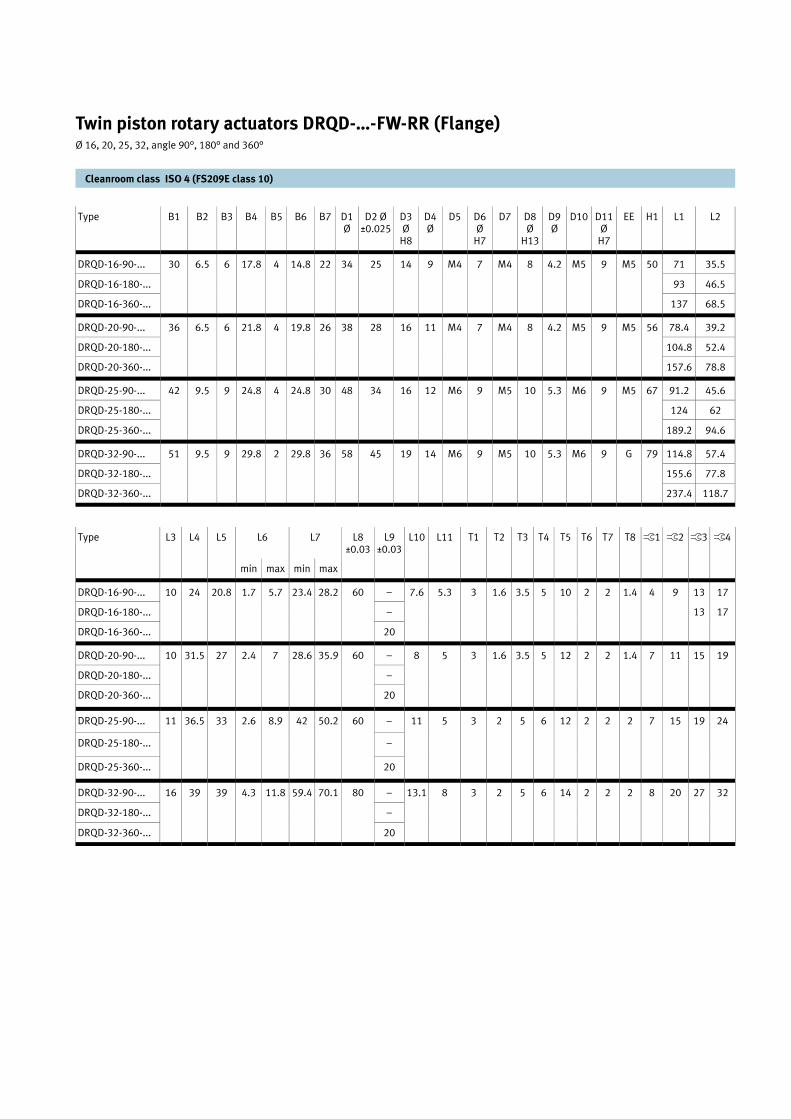
Twin piston rotary actuators DRQD-…-FW-RR (Flange) Ø 16, 20, 25, 32, angle 90°, 180° and 360°
Sensor slots for type SME-/
SMT-8-... proximity sensors
Self-adjusting shock absorb-
ers for end position cushion-
ing
Adjustable sleeve for end
position cushioning with type
DRQD-...YSRJ
1
2
3
Internal hex-head screw for
end position adjustment
with integral regulating
screw for end position
cushioning
Model PPVJ: Both air con-
nections on one cap, op-
tionally at
front or side.
Model YSRJ: Both air con-
nections on one cap, at
side only.
Woodruff key position at 0°
Centering sleeves (2 ea.
Included in scope of deliv-
ery)
Centering sleeves (not
included in scope of deliv-
ery)
4
5
6
7
aJ
aA
Cleanroom class ISO 4 (FS209E class 10)
Twin piston rotary actuators DRQD-…-FW-RR (Flange) Ø 16, 20, 25, 32, angle 90°, 180° and 360°
Type B1 B2 B3 B4 B5 B6 B7 D1 Ø
D2 Ø ±0.025
D3 Ø
H8
D4 Ø
D5 D6 Ø
H7
D7 D8 Ø
H13
D9 Ø
D10 D11 Ø
H7
EE H1 L1 L2
DRQD-16-90-... 30 6.5 6 17.8 4 14.8 22 34 25 14 9 M4 7 M4 8 4.2 M5 9 M5 50 71 35.5
DRQD-16-180-... 93 46.5
DRQD-16-360-... 137 68.5
DRQD-20-90-... 36 6.5 6 21.8 4 19.8 26 38 28 16 11 M4 7 M4 8 4.2 M5 9 M5 56 78.4 39.2
DRQD-20-180-... 104.8 52.4
DRQD-20-360-... 157.6 78.8
DRQD-25-90-... 42 9.5 9 24.8 4 24.8 30 48 34 16 12 M6 9 M5 10 5.3 M6 9 M5 67 91.2 45.6
DRQD-25-180-... 124 62
DRQD-25-360-... 189.2 94.6
DRQD-32-90-... 51 9.5 9 29.8 2 29.8 36 58 45 19 14 M6 9 M5 10 5.3 M6 9 G 79 114.8 57.4
DRQD-32-180-... 155.6 77.8
DRQD-32-360-... 237.4 118.7
Type L3 L4 L5 L6 L7 L8 ±0.03
L9 ±0.03
L10 L11 T1 T2 T3 T4 T5 T6 T7 ß1 ß2 ß3 ß4
min max min max
DRQD-16-90-... 10 24 20.8 1.7 5.7 23.4 28.2 60 – 7.6 5.3 3 1.6 3.5 5 10 2 2 4 9 13 17
DRQD-16-180-... – 13 17
DRQD-16-360-... 20
DRQD-20-90-... 10 31.5 27 2.4 7 28.6 35.9 60 – 8 5 3 1.6 3.5 5 12 2 2 7 11 15 19
DRQD-20-180-... –
DRQD-20-360-... 20
DRQD-25-90-... 11 36.5 33 2.6 8.9 42 50.2 60 – 11 5 3 2 5 6 12 2 2 7 15 19 24
DRQD-25-180-... –
DRQD-25-360-... 20
DRQD-32-90-... 16 39 39 4.3 11.8 59.4 70.1 80 – 13.1 8 3 2 5 6 14 2 2 8 20 27 32
DRQD-32-180-... –
DRQD-32-360-... 20
T8
1.4
1.4
2
2

Double acting cylinder with flexi-
ble cushioning rings in the end
positions and contact-less sens-
ing.
DSNU-…-P-A-RR-SA
Double acting cylinder with ad-
justable cushioning rings in the
end positions and contact-less
sensing.
DSNU-…-PPV-A-RR-SA
Order example:
Part no: 15024262
Type: DSNU-20-100-PPV-A-RR-SA
Double acting cylinder Ø 20 mm,
stroke 200 mm, with adjustable
cushioning rings in the end posi-
tions and contact-less sensing.
Accessories
Proximity sensor for fitting in 8
mm slot
SME-8.../SMT-8-...
Swivel mounting
WBN-...
Clevis foot
LBN-...
– Optimum graded range of
piston diameters and stroke
lengths
– Quick reacting thanks to
minimal break-away force
which is effective at approx.
0.6 bar.
– Good running performance
and long service life thanks
to smooth, hard cylinder
bore
– Piston rod and cylinder bar-
rel made of stainless steel
– With flexible cushioning
rings in the end positions
– With adjustable end-position
cushioning at both ends
– With or without contact less
end position sensing
Mounting bracket for proximity
sensor
SMBR-8-...
Mounting options
Foot mounting
HBN-… x1
HBN-… x2
Flange mounting
FBN-...
Cleanroom class ISO 4 (FS209E class 10)
Standard cylinders DSNU-…-RR-SA Ø 8, 10, 16, 20, 25 mm, stroke 10 to 500 mm
Type Part no. Pis-ton Ø
Stroke [mm]
Thrust at 6 bar
Return force
Air cushioning Con-nection
Bracket for SME-8/SMT-8 sensor
Part no.
[mm] [N] [N] [cushioning length]
DSNU-8-…-P-A-RR-SA 15024250 8 10…100 30 23 Damper M5 SMBR-8-8-RR 15025013
DSNU-10-…-P-A-RR-SA 15024251 10 10 …100 47 40 Damper M5 SMBR-8-10-RR 15025014
DSNU-12-…-P-A-RR-SA 15024256 12 10 …200 68 51 Damper M5 SMBR-8-12-RR 15025015
DSNU-16-…-PPV-A-RR-SA 15024260 16 10 …200 121 104 Adjustable [14 mm] M5 SMBR-8-16-RR 15025016
DSNU-20-…-PPV-A-RR-SA 15024262 20 10 …320 189 158 Adjustable [17 mm] G1/8 SMBR-8-20-RR 15025017
DSNU-25-…-PPV-A-RR-SA 15024265 25 10 …500 295 247 Adjustable [17 mm] G1/8 SMBR-8-25-RR 15025018

+ = plus stroke length
Cleanroom class ISO 4 (FS209E class 10)
Standard cylinders DSNU-…-RR-SA Ø 8, 10, 16, 20, 25 mm, stroke 10 to 500 mm
Ø AM B BE BF BF1 CD D D4 EE EW KK KV KW
[mm] h9 Ø Ø Ø
8 12 12 M12x1.25 12 15 4 15 9.3 M5 8 M4 19 6
10 12 12 M12x1.25 12 15 4 15 11.3 M5 8 M4 19 6
12 16 16 M16x1.5 17 16 6 20 13.3 M5 12 M6 24 8
16 16 16 M16x1.5 17 17 6 20 17.3 M5 12 M6 24 8
20 20 22 M22x1.5 20 20 8 27 21.3 G1/8 16 M8 32 11
25 22 22 M22x1.5 22 22 8 27 26.5 G1/8 16 M10x1.25 32 11
Ø L L2 MM PL PL1 PL2 PC VD WF1 XC ZJ ZM SW
[mm] Ø f8
8 6 68.5 4 6 8 22.5 20.5 2 19 86.5 84.5 74 –
10 6 68.5 4 6 8 22.5 20.5 2 19 86.5 84.5 74 –
12 9 77.5 6 6 8 27.5 25.5 2 21 102.5 99.5 94 5
16 9 82 6 6 6 26 26 2 22 108 104 110 5
20 12 102 8 8.2 8.2 34 34 2 24 129 126 116.4 7
25 12 105.5 10 8.2 8.2 36 36 2 28 140 133.5 124.4 9
Vacuum suction port 1
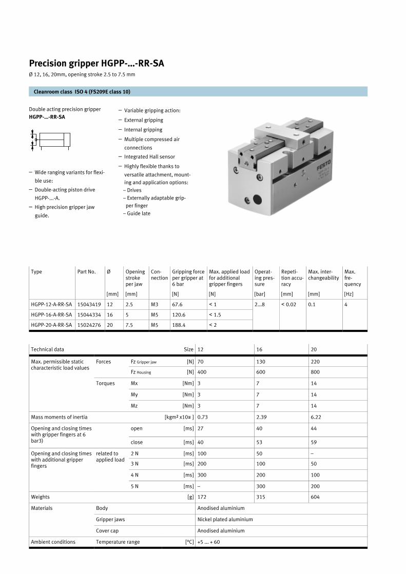
Double acting precision gripper
HGPP-…-RR-SA
– Wide ranging variants for flexi-
ble use:
– Double-acting piston drive
HGPP-...-A.
– High precision gripper jaw
guide.
– Variable gripping action:
– External gripping
– Internal gripping
– Multiple compressed air
connections
– Integrated Hall sensor
– Highly flexible thanks to
versatile attachment, mount-
ing and application options:
– Drives
– Externally adaptable grip-
per finger
– Guide late
Precision gripper HGPP-…-RR-SA Ø 12, 16, 20mm, opening stroke 2.5 to 7.5 mm
Cleanroom class ISO 4 (FS209E class 10)
Type Part No. Ø Opening stroke per jaw
Con-nection
Gripping force per gripper at 6 bar
Max. applied load for additional gripper fingers
Operat-ing pres-sure
Repeti-tion accu-racy
Max. inter-changeability
Max. fre-quency
[mm] [mm] [N] [N] [bar] [mm] [mm] [Hz]
HGPP-12-A-RR-SA 15043419 12 2.5 M3 67.6 < 1 2...8 < 0.02 0.1 4
HGPP-16-A-RR-SA 15044334 16 5 M5 120.6 < 1.5
HGPP-20-A-RR-SA 15024276 20 7.5 M5 188.4 < 2
Technical data Size 12 16 20
Max. permissible static characteristic load values
Forces Fz Gripper jaw [N] 70 130 220
Fz Housing [N] 400 600 800
Torques Mx [Nm] 3 7 14
My [Nm] 3 7 14
Mz [Nm] 3 7 14
Mass moments of inertia [kgm² x10p ] 0.73 2.39 6.22
Opening and closing times with gripper fingers at 6 bar3)
open [ms] 27 40 44
close [ms] 40 53 59
Opening and closing times with additional gripper fingers
related to applied load
2 N [ms] 100 50 –
3 N [ms] 200 100 50
4 N [ms] 300 200 100
5 N [ms] – 300 200
Weights [g] 172 315 604
Materials Body Anodised aluminium
Gripper jaws Nickel plated aluminium
Cover cap Anodised aluminium
Ambient conditions [°C] +5 ... + 60 Temperature range

Precision gripper HGPP-…-RR-SA Ø 12, 16, 20mm, opening stroke 2.5 to 7.5 mm
Cleanroom class ISO 4 (FS209E class 10)
Ø B1 B2 B3 B4 B5 B6 B7 B8 D1 D2 D4
[mm] +0.3 +0.3 ±0.1 ±0.1 ±0.02 ±0.1 ±0.1 Ø
HGPP-12-... 38 38 13 30 8 12.5 30 24±0.02 M4 3.3 M3
HGPP-16-... 42 42 17 32 10 16 32 25±0.02 M4 3.3 M3
HGPP-20-... 48 48 20 40 12 20 40 31+0.1 M5 4.2 M4
Ø D5 D6 D7 D8 EE EE1 H1 H2 H3 H4 H5
[mm] Ø H8 Ø H8 Ø +0.2 ±0.1 ±0.1 ±0.02
HGPP-12-... 2 2 M3 6 M3 M3 40.2 +0.2 35.5 8.5 ±0.3 4.7 2
HGPP-16-... 2.5 2.5 M3 8 M5 M5 51.5 +0.3 40.9 8.3 ±0.2 6.8 3
HGPP-20-... 3 3 M3 8 M5 M5 57.5 +0.3 53.48 15.5 ±0.2 8 3
Ø H6 H7 L1 L2 L3 L4 L5 L6 L7 L8 L9
[mm] ±0.12 ±0.5 ±0.5 ±0.25 ±0.05 ±0.1 ±0.1 ±0.1 ±0.02
HGPP-12-... 5 32.7 +0.2 67 62 60 51.4 8 30 6 9 14
HGPP-16-... 5 37.1 +0.3 98 88 86 76 13 40 6 14 17.5
HGPP-20-... 7 48.5 +0.3 120 105 103 92 13 40 8 ±0.1 20 21
Ø L10 L11 T1 T2 T3 T4 T5 T6 T7 T8 T9
[mm] ±0.05 ±0.1 ±0.1 ±0.1 0.1
HGPP-12-... 8.5 18 8 16 +0.4/–0.2 6 7.5 5 4 6 5.5 1.2
HGPP-16-... 11.5 24 10 19.5 +0.5/–0.2 7 ±0.1 8 6 4.5 6 5 1.2
HGPP-20-... 13.5 26 12 28.5 +0.5/–0.2 7 ±0.1 10 8 ±0.1 7 ±0.1 8 ±0.1 6 1.2
Supply port, opening
Supply port, closing
Hole for locating pin
(Locating pins are not in-
cluded in scope of delivery.)
Gripper jaws open
Gripper jaws closed
Hole for sensor
Gripper
Adapter example for direct air
supply
O-ring for precision grippers:
HGPP-12: 3x1.5
HGPP-16: 5x1.5
HGPP-20: 5x1.5
Set screw for securing the
Hall sensor
Vacuum suction port
1
23
45
6
7
8
9
aJ
aA

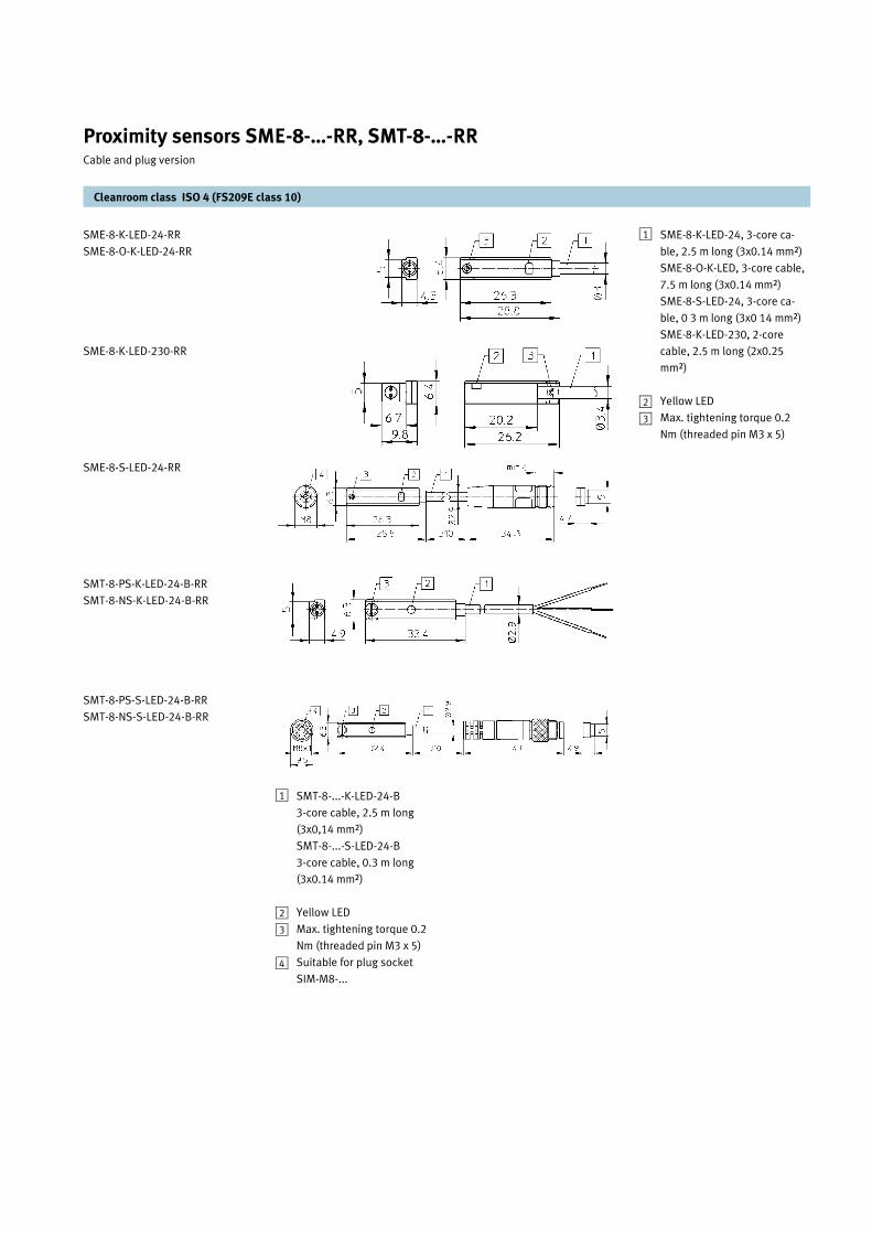
SME-8-K-LED-230-RR
SME-8-O-K-LED-24-RR
SMT-8-PS-K-LED-24-B-RR
SMT-8-PS-S-LED-24-B-RR
SMT-8-NS-K-LED-24-B-RR
SMT-8-NS-S-LED-24-B-RR
Proximity sensors for cylinders
with 8 mm slot. Contact-type
(reed switch)
SME-8-…-RR
Proximity sensors for cylinders
with 8 mm slot. Contact-less
(electronic switch)
SMT-8-…-RR
– with LED
– With plug
– With cable (2x0.14 mm²)
– CE
– Compact design
– Suitable for a wide variety of
Festo cylinders
– Fast and reliable due to simple
clamping into the sensor slot
– System optimised
– Can also be mounted on round
section cylinders using special
mounting kit
SME-8-K-LED-24-RR
SME-8-S-LED-24-RR
Sensor with plug version
SME-8-S-...
SMT-8-S-...
Angled plug with cable
SIM-M8-3WD-…
Sensor with 2.5 m cable version
SME-8-K-...
SME-8-K-…
Straight plug with cable
SIM-M8-3GD-...
Cleanroom class ISO 4 (FS209E class 10)
Proximity sensors SME-8-…-RR, SMT-8-…-RR Cable and plug version
Type Part No. Version Connection Contact rating
Switching current
Switching voltage
Contact resistance
Switching frequency
Weight
SME contact-type, reed switch
SME-8-S-LED-24-RR 15024688 M8 Plug 3-pin M8 10 W 500 mA 12...30 V DC 0.09 800 Hz 0.01 kg
SME-8-K-LED-24-RR 15024689 Cable 2.5 m 3-core ca-ble, 2.5 m
10 W 500 mA 12...30 V DC 0.13 800 Hz 0.05 kg
SME-8-K-LED-230-RR 15024692 230 V 2-core ca-ble, 2.5 m
10 W AC: 200 mA DC: 120 mA
3...250 V 0.15 500 Hz 0.06 kg
SME-8-O-K-LED-24-RR 15024695 NC contact 3-core ca-ble, 2.5 m
2 W 50 mA 12...30 V DC 32 500 Hz 0.085 kg
SMT contact-less type, electronic switch
SMT-8-PS-S-LED-24-B-RR 15024702 M8 Plug 3-pin M8 3 W 100 mA 12...30 V DC - PNP 0.02 kg
SMT-8-PS-K-LED-24-B-RR 15024707 Cable 2.5 m 3-core ca-ble, 2.5 m
3 W 100 mA 12...30 V DC - PNP 0.08 kg
SMT-8-NS-S-LED-24-B-RR 15024709 M8 Plug 3-pin M8 3 W 100 mA 12...30 V DC - NPN 0.02 kg
SMT-8-NS-K-LED-24-B- RR 15024710 Cable 2.5 m 3-core ca-ble, 2.5 m
3 W 100 mA 12...30 V DC - NPN 0.08 kg
M8 plug socket with cable (3 pins) Type Part no.
Straight plug socket 2.5 m SIM-M8-3GD-2,5-PU-RR 15024996
5 m SIM-M8-3GD-5-PU-RR 15024997
10 m SIM-M8-3GD-10-PU-RR 15024998
2.5 m SIM-M8-3WD-2,5-PU-RR 15024999
5 m SIM-M8-3WD-5-PU-RR 15025002
10 m SIM-M8-3WD-10-PU-RR 15025003
Angled plug socket
SME-8-K-LED-24-RR
SME-8-O-K-LED-24-RR
SME-8-K-LED-230-RR
SME-8-S-LED-24-RR
SMT-8-PS-K-LED-24-B-RR
SMT-8-NS-K-LED-24-B-RR
SMT-8-PS-S-LED-24-B-RR
SMT-8-NS-S-LED-24-B-RR
Proximity sensors SME-8-…-RR, SMT-8-…-RR Cable and plug version
Cleanroom class ISO 4 (FS209E class 10)
SMT-8-...-K-LED-24-B
3-core cable, 2.5 m long
(3x0,14 mm²)
SMT-8-...-S-LED-24-B
3-core cable, 0.3 m long
(3x0.14 mm²)
Yellow LED
Max. tightening torque 0.2
Nm (threaded pin M3 x 5)
Suitable for plug socket
SIM-M8-...
1
2
3
4
SME-8-K-LED-24, 3-core ca-
ble, 2.5 m long (3x0.14 mm²)
SME-8-O-K-LED, 3-core cable,
7.5 m long (3x0.14 mm²)
SME-8-S-LED-24, 3-core ca-
ble, 0 3 m long (3x0 14 mm²)
SME-8-K-LED-230, 2-core
cable, 2.5 m long (2x0.25
mm²)
Yellow LED
Max. tightening torque 0.2
Nm (threaded pin M3 x 5)
1
2
3

Important technical data:
– For used in Cleanroom class
ISO 4 (FS209E class 10),
max. speed should be less
than 0.3 m/s
– For used in Cleanroom class
ISO 5 (FS209E class 100),
max. speed should be less
than 1.0 m/s
– To achieved the least parti-
cle emission during clean-
room application it is recom-
mended to ensure sufficient
damping when the rodless
cylinder come to the end of
the stroke. This can be
achieved by optimising the
in-build pneumatic end
cushioning or to attach a
external shock absorber.
Accessories
Foot mounting
HNC-40 for DGE-25-…-RR-SA
HNC-63 for DGPL-32-…-RR-SA
and DGE-40-…-RR-SA
Sensor cable
SIM-M8-3…-RR
(Refer to page 32)
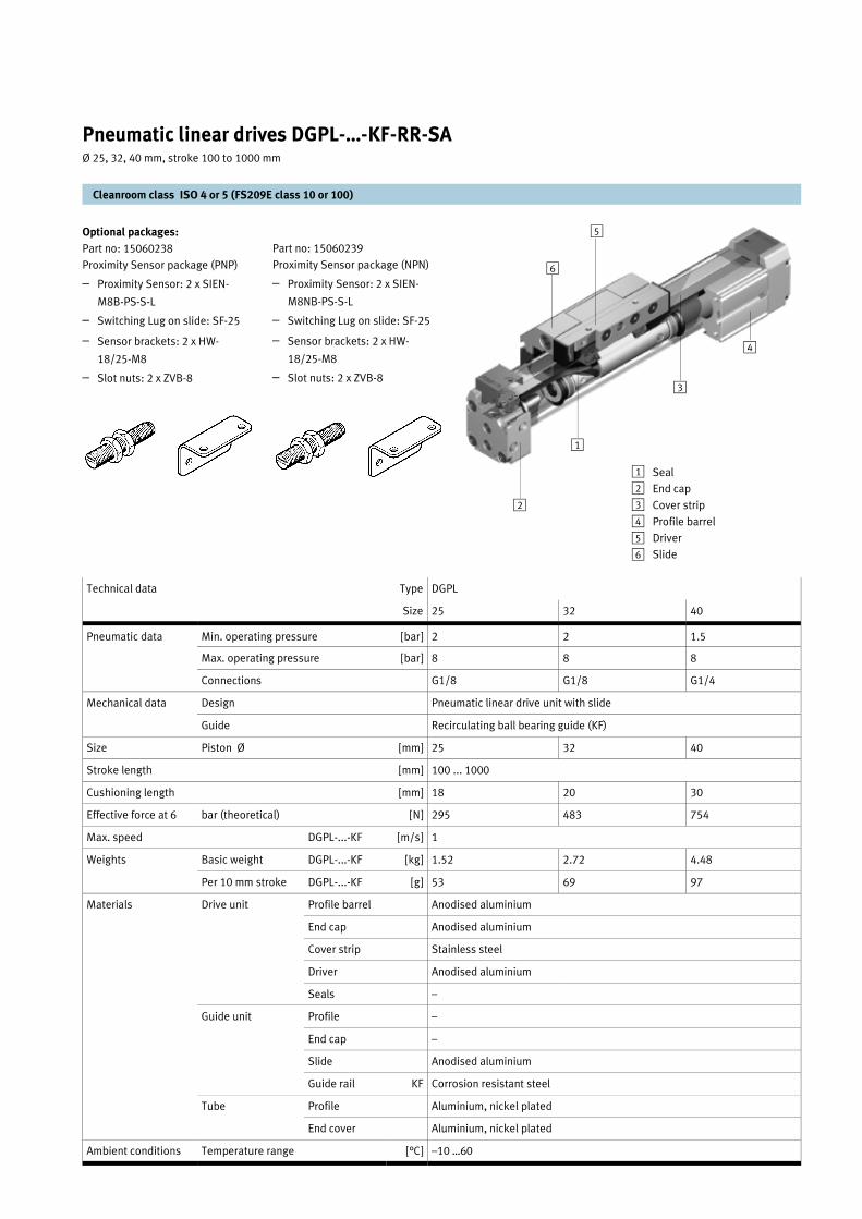
Double acting, pneumatic linear
drive units with slide, adjustable
end-position cushioning and re-
circulating ball bearing guides
DGPL-...-KF-RR-SA
– Precision, rigid guide
– Greater flexibility thanks to
wide choice of mounting and
assembly options
– Variable end-position cushion-
ing systems
– Wide range of options for
mounting on drive units
– System product for position-
ing, handling and assembly
technology
Order example:
Part no: 15059878
Type DGPL-32-500-PPV-A-B-KF-
RR-SA
Double acting linear drive, Ø 32
mm, stroke 500 mm, with adjust-
able end-position cushioning and
recirculating ball bearing guides
Cleanroom class ISO 4 or 5 (FS209E class 10 or 100)
Pneumatic linear drives DGPL-…-KF-RR-SA Ø 25, 32, 40 mm, stroke 100 to 1000 mm
Type Part No. Piston Ø [mm]
Stroke [mm]
Theoretical force at 6 bar [N]
Cushioning length [mm]
Connection
DGPL-25-…-PPV-A-B-KF-RR-SA 15059877 25 100…1000 295 18 G1/8
DGPL-32-…-PPV-A-B-KF-RR-SA 15059878 32 100…1000 483 20 G1/8
DGPL-40-…-PPV-A-B-KF-RR-SA 15059879 40 100…1000 754 30 G1/4
Part no: 15060241
– Shock absorber package for
DGPL-32-…-RR-SA and DGPL-
40-…-RR-SA
– Shock absorber: 2 x YSR-16-
20-C
– Shock absorber retainer: 2 x
KYP-40-SA
Optional packages:
Part no: 15060240
Shock absorber package for
DGPL-25-…-RR-SA
– Shock absorber: 2 x YSR-12-
12-C (2x)
– Shock absorber retainer: 2 x
KYP-25-SA
Cleanroom class ISO 4 or 5 (FS209E class 10 or 100)
Pneumatic linear drives DGPL-…-KF-RR-SA Ø 25, 32, 40 mm, stroke 100 to 1000 mm
Technical data Type DGPL
Size 25 32 40
Pneumatic data Min. operating pressure [bar] 2 2 1.5
Max. operating pressure [bar] 8 8 8
Connections G1/8 G1/8 G1/4
Mechanical data Design Pneumatic linear drive unit with slide
Guide Recirculating ball bearing guide (KF)
Size Piston Ø [mm] 25 32 40
Stroke length [mm] 100 ... 1000
Cushioning length [mm] 18 20 30
Effective force at 6 bar (theoretical) [N] 295 483 754
Max. speed DGPL-...-KF [m/s] 1
Weights Basic weight DGPL-...-KF [kg] 1.52 2.72 4.48
Per 10 mm stroke DGPL-...-KF [g] 53 69 97
Materials Drive unit Profile barrel Anodised aluminium
End cap Anodised aluminium
Cover strip Stainless steel
Driver Anodised aluminium
Seals –
Guide unit Profile –
End cap –
Slide Anodised aluminium
Guide rail KF Corrosion resistant steel
Ambient conditions Temperature range [°C] –10 …60
Tube Profile Aluminium, nickel plated
End cover Aluminium, nickel plated
Part no: 15060239
Proximity Sensor package (NPN)
– Proximity Sensor: 2 x SIEN-
M8NB-PS-S-L
– Switching Lug on slide: SF-25
– Sensor brackets: 2 x HW-
18/25-M8
– Slot nuts: 2 x ZVB-8
Optional packages:
Part no: 15060238
Proximity Sensor package (PNP)
– Proximity Sensor: 2 x SIEN-
M8B-PS-S-L
– Switching Lug on slide: SF-25
– Sensor brackets: 2 x HW-
18/25-M8
– Slot nuts: 2 x ZVB-8
1
2
3
4
5
6
Seal
End cap
Cover strip
Profile barrel
Driver
Slide
1
23
4
5
6
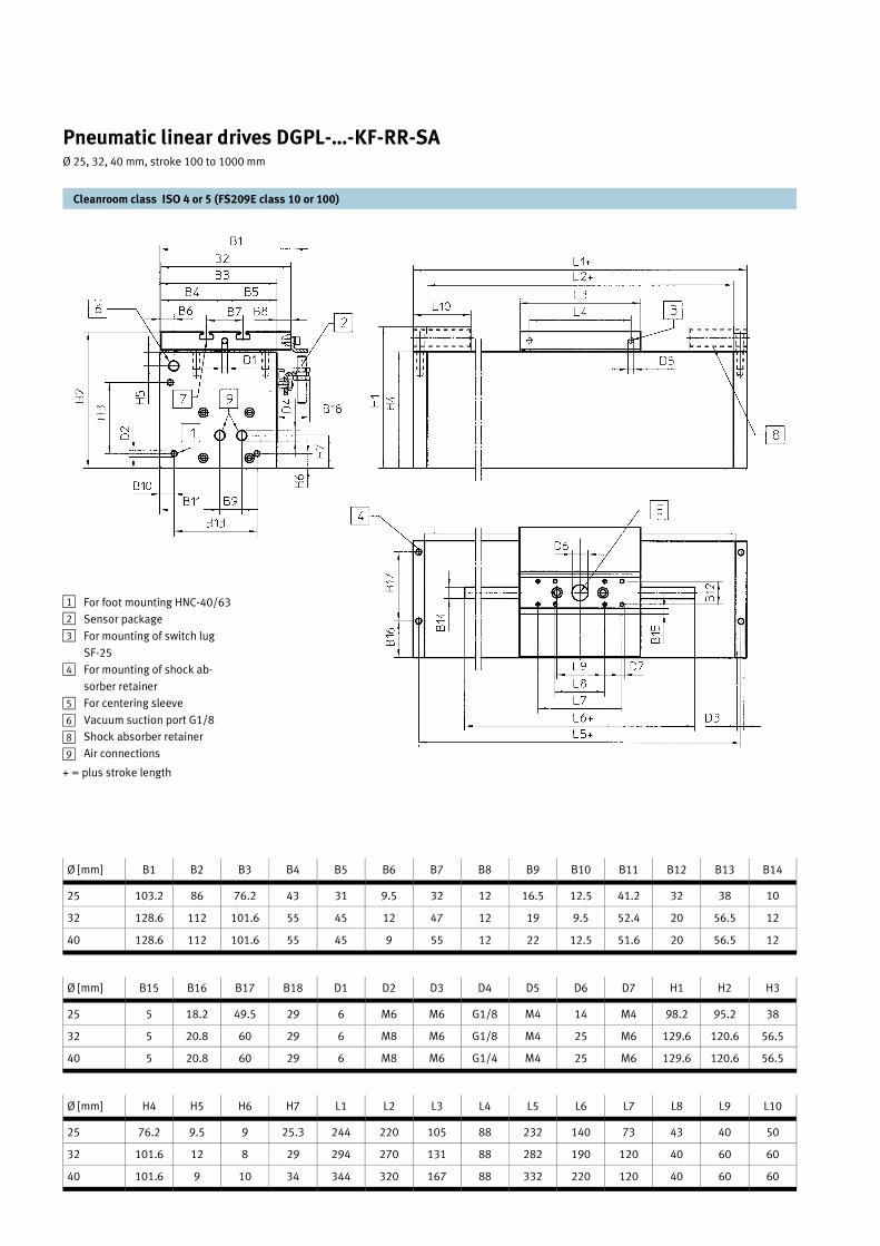
Pneumatic linear drives DGPL-…-KF-RR-SA Ø 25, 32, 40 mm, stroke 100 to 1000 mm
Cleanroom class ISO 4 or 5 (FS209E class 10 or 100)
Ø [mm] B1 B2 B3 B4 B5 B6 B7 B8 B9 B10 B11 B12 B13 B14
25 103.2 86 76.2 43 31 9.5 32 12 16.5 12.5 41.2 32 38 10
32 128.6 112 101.6 55 45 12 47 12 19 9.5 52.4 20 56.5 12
40 128.6 112 101.6 55 45 9 55 12 22 12.5 51.6 20 56.5 12
Ø [mm] B15 B16 B17 B18 D1 D2 D3 D4 D5 D6 D7 H1 H2 H3
25 5 18.2 49.5 29 6 M6 M6 G1/8 M4 14 M4 98.2 95.2 38
32 5 20.8 60 29 6 M8 M6 G1/8 M4 25 M6 129.6 120.6 56.5
40 5 20.8 60 29 6 M8 M6 G1/4 M4 25 M6 129.6 120.6 56.5
Ø [mm] H4 H5 H6 H7 L1 L2 L3 L4 L5 L6 L7 L8 L9 L10
25 76.2 9.5 9 25.3 244 220 105 88 232 140 73 43 40 50
32 101.6 12 8 29 294 270 131 88 282 190 120 40 60 60
40 101.6 9 10 34 344 320 167 88 332 220 120 40 60 60
For foot mounting HNC-40/63
Sensor package
For mounting of switch lug
SF-25
For mounting of shock ab-
sorber retainer
For centering sleeve
Vacuum suction port G1/8
Shock absorber retainer
Air connections
1
2
3
4
56
8
9
+ = plus stroke length

Clamping module
EV-…-RR
– Single-acting
– Flat space-saving construction
– Hermetically sealed
– Ideal for clamping tasks
– Pressure plate to protect dia-
phragm
– For application against abra-
sive surfaces, a metal pressure
plate can be snap-fitted to the
diaphragm to protect it against
external damage. Type; EV-…-
DP.
– Housing; Al die-cast. Dia-
phragm; polyurethane
For rapid clamping of sensitive
and slightly uneven workpieces
with small dimensional devia-
tions. This cylinder series is
suitable for installation in all
types of handling devices.
The flat design and relatively
high clamping forces make the
cylinders particularly suitable
for clamping block-shaped
workpieces.
As the cylinders
do not have any stroke limita-
tion, they should be operated
only against a workpiece. The
return force is provided by the
pre-tensioned diaphragm.
Cleanroom class ISO 5 (FS209E class 100)
Clamping modules EV-…-RR Ø 12, 16, 20, 25, 32, 40, 50, 63 mm, stroke 3 to 5 mm
Type Part No. Piston Ø Stroke Clamping force at 6 bar [N]
[mm] [mm] Stroke 1mm Stroke max.
EV-12-3-RR 15024495 12 3 55 56
EV-16-4-RR 15024496 16 4 102 125
EV-20-4-RR 15024497 20 4 162 187
EV-25-4-RR 15024498 25 4 226 271
EV-32-5-RR 15024499 32 5 376 456
EV-40-5-RR 15024500 40 5 680 675
EV-50-5-RR 15024501 50 5 1090 1075
EV-63-5-RR 15024502 63 5 1660 1640
Type B1 B2 B3 D1 Ø D2 Ø D3 D4 Ø D5 Ø D6 Ø H1 H2 H3 H4 H5 L1 L2
EV-12-3-RR 29 16.5 13 3.5 2 M3 6.5 3 11 10.5 3 4 3.5 1.5 25 18
EV-16-4-RR 33 18.5 15 3.5 2 M3 6.5 7 15 10.5 4 4 3.5 1.5 29 22
EV-20-4-RR 37 20.5 16.5 4.5 2 M3 6.5 11 19 10.5 4 4 3.5 1.5 33 25
EV-25-4-RR 42 23 18.5 5.5 2 M3 6.5 16 24 10.5 4 4 3.5 1.5 38 28
EV-32-5-RR 49 26.5 21 5.5 2 M3 6.5 23 31 10.5 5 4 3.5 1.5 45 34
EV-40-5-RR 57 30.5 25 5.5 2 M3 6.5 31 39 10.5 5 4 2.5 1.6 53 42
EV-50-5-RR 67 35.5 29 5.5 2 M3 6.5 41 49 10.5 5 4 2.5 1.6 63 49
EV-63-5-RR 80 42 34 5.5 2 M3 6.5 54 62 10.5 5 4 2.5 1.6 76 60
Max. permissible stroke
against stop (workpiece)
Clamping area
The pressure plate can be
snap fitted onto the dia-
phragm of the clamping mod-
ule
1
2
3

Trunnion mounting
ZNCM-…, LNZG-...
Swivel mounting
SNCL-…, SNCB-...
Swivel mounting
SNCB-…, LNG-..., LSN-...
Trunnion flange mounting
ZNCF-…, LNZG-...
Swivel mounting
SNC-…, LSNG-...
Swivel mounting
SNCS-…, LBG-...
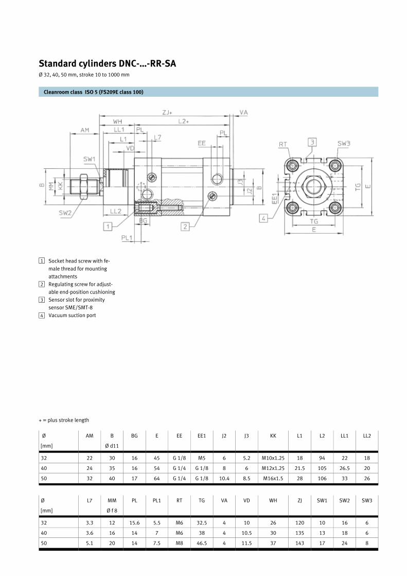
Double-acting standard cylinders
with adjustable end-position
cushioning
DNC-...-PPV-RR-SA
Double-acting standard cylinders
with contactless end-position
sensing and adjustable end-
position cushioning
DNC-...-PPV-A-RR-SA
– The modern design and con-
struction saves up to 11%
more space compared to ordi-
nary standard cylinders.
– The proximity sensors sit flush
in the profile slot. There is
therefore no need for an addi-
tional mounting kit.
– An extensive range of mount-
ing accessories makes it possi-
ble to install the solution virtu-
ally anywhere.
– The widest range of variants on
the market provides the right
DNC cylinder for every applica-
tion.
– These standard cylinders com-
ply with the following stan-
dards:
– ISO 6431 (international)
– DIN ISO 6431 and
– VDMA 24 562 (Germany)
– NF E 49 003.1 (France)
– UNI 10 290 (Italy)
Order example:
Part no: 15024244
Type: DNC-50-500-PPV-A-RR-
SA
Double-acting standard cylin-
ders, diameter 50 mm, stroke
500 mm, with contactless end-
position sensing and adjust-
able end-position cushioning
Mounting options
Foot mounting
HNC-…
Flange mounting
FNC-…
Proximity sensor
SME-8-…, SMT-8-...
Standard cylinders DNC-…-RR-SA Ø 32, 40, 50 mm, stroke 10 to 1000 mm
Cleanroom class ISO 5 (FS209E class 100)
Type [without mag-netic piston]
Part No. Type [with magnetic piston]
Part No. Piston Ø [mm]
Stroke [mm]
Thrust at 6 bar [N]
Return force [N]
Cushioning length [mm]
Connec-tion
DNC-32-…-PPV-RR-SA 15024237 DNC-32-…-PPV-A-RR-SA 15024157 32 10 …1000 483 415 20 G1/8
DNC-40-…-PPV-RR-SA 15024238 DNC-40-…-PPV-A-RR-SA 15024243 40 10 …1000 754 633 20 G1/4
DNC-50-…-PPV-RR-SA 15024240 DNC-50-…-PPV-A-RR-SA 15024244 50 10 …1000 1178 990 22 G1/4
+ = plus stroke length
Standard cylinders DNC-…-RR-SA Ø 32, 40, 50 mm, stroke 10 to 1000 mm
Cleanroom class ISO 5 (FS209E class 100)
Ø AM B BG E EE EE1 J2 J3 KK L1 L2 LL1 LL2
[mm] Ø d11
32 22 30 16 45 G 1/8 M5 6 5.2 M10x1.25 18 94 22 18
40 24 35 16 54 G 1/4 G 1/8 8 6 M12x1.25 21.5 105 26.5 20
50 32 40 17 64 G 1/4 G 1/8 10.4 8.5 M16x1.5 28 106 33 26
Ø L7 MM PL PL1 RT TG VA VD WH ZJ SW1 SW2 SW3
[mm] Ø f 8
32 3.3 12 15.6 5.5 M6 32.5 4 10 26 120 10 16 6
40 3.6 16 14 7 M6 38 4 10.5 30 135 13 18 6
50 5.1 20 14 7.5 M8 46.5 4 11.5 37 143 17 24 8
Socket head screw with fe-
male thread for mounting
attachments
Regulating screw for adjust-
able end-position cushioning
Sensor slot for proximity
sensor SME/SMT-8
Vacuum suction port
1
2
3
4

Standard servo motor
MTR-AC-...
Important technical data:
– For used in Cleanroom class
ISO 4 (FS209E class 10),
max. speed should be 0.5
m/s and max. acceleration 1
m/s²
– For used in Cleanroom class
ISO 5 (FS209E class 100),
max. speed should be 1.5
m/s and max. acceleration 4
m/s²
– Repetition accuracy: ± 0.1
mm
– Ambient temperature: 0…
+40°C
– Protection class on cover
strip: IP 40
– To simplify ordering only
one type is included in the
Cleanroom product range.
Please contact Festo for
other variations
Accessories:
Single phase motor controller
(for used with PNP sensors)
SEC-AC-305/PO1
Electromechanical axes
Tooth belt drives units with slide,
and recirculating ball bearing
guides housed into a tube profile
with end cover plates.
DGE-25-...-ZR-LK-RV-KG-KF-RR-SA
– Precision, rigid guide
– Greater flexibility thanks to wide
choice of mounting and assem-
bly options
– Wide range of options for
mounting on drive units
– Comprehensive range of mount-
ing accessories for multi-axis
combinations
– Optimally adapted motor con-
troller combinations
Order example:
Part no: 15059855
Type DGE-25-500-ZR-LK-RV-KG-KF-
RR-SA
Electrical axes, tooth belt linear
drive, Ø 25 mm, stroke 500 mm
ZR: With tooth belt
LK: No drive on left
RV: Drive shaft on right, front
KG: Drive come with coupling hous-
ing and motor flange
KF: Recirculating ball bearing
guides
RR-SA: Product modified for clean-
room use
Material:
Drive profile barrel: Anodised alu-
minium
Tube with end plates: Aluminium,
nickel plated
Cleanroom class ISO 4 or 5 (FS209E class 10 or 100)
Toothed belt drives DGE-...-ZR-LK-RV-KG-KF-RR-SA Ø 25, 40 mm, stroke 100 to 1000 mm
Type Part No. Piston Ø Stroke Max. feed force
[mm] [mm] [N] Type Indexing [mm]
Width [mm]
Effective radius [mm]
Feed constant [mm/rev]
DGE-25-...-ZR-LK-RV-KG-KF-RR-SA 15059855 25 100…1000 260 15LL-3MR-35M-610
3 15 20.05 63
DGE-40-...-ZR-LK-RV-KG-KF-RR-SA 15059856 40 100…1000 610 25LL-5MR-30M-610
5 25 31.83 100
Toothed belt
Foot mounting
HNC-40 for DGE-25-…-RR
HNC-63 for DGE-40-…-RR
Sensor cable
SIM-M8-…-RR
(Refer to page 32)

Optional packages:
Part no: 15060234 Basic servo motor package (used with PNP sensors) for DGE-25-…-ZR-…-RR consisted of: – Motor controller: SEC-AC-305/PO1 – Standard servo motor: MTR-AC-70-3S-AA – Coupling: KSE-30-D08-D11
– Cable set (5 m): KSEC-AC-5
Part no: 15060235 Basic servo motor package (used with PNP sensors) for DGE-40-…-ZR-…-RR consisted of: – Motor controller: SEC-AC-305/PO1 – Standard servo motor: MTR-AC-100-3S-AA – Coupling: KSE-40-D15-D19
– Cable set (5 m): KSEC-AC-5
Cleanroom class ISO 4 or 5 (FS209E class 10 or 100)
Toothed belt drives DGE-...-ZR-LK-RV-KG-KF-RR-SA Ø 25, 40 mm, stroke 100 to 1000 mm
1
2
3
4
5
6
Toothed belt Drive shaft/trunnion Coupling housing Profile barrel Driver Slide
1
2
3
45
6
Part no: 15060238 Proximity Sensor package (PNP) – Proximity Sensor: 2 x SIEN-
M8B-PS-S-L – Switching Lug on slide: SF-25
– Sensor brackets: 2 x HW-18/25-M8
– Slot nuts: 2 x ZVB-8
Part no: 15060239 Proximity Sensor package (NPN) – Proximity Sensor: 2 x SIEN-
M8NB-PS-S-L – Switching Lug on slide: SF-25
– Sensor brackets: 2 x HW-18/25-M8
– Slot nuts: 2 x ZVB-8
Part no: 15060240 Shock absorber package for DGE-25-…-RR-SA – Shock absorber: 2 x YSR-12-
12-C (2x) – Shock absorber retainer: 2 x
KYP-25-SA
Part no: 15060241 Shock absorber package for DGE-40-…-RR-SA – Shock absorber: 2 x YSR-16-
20-C – Shock absorber retainer: 2 x
KYP-40-SA

Important technical data:
– For used in Cleanroom class
ISO 4 (FS209E class 10),
max. speed should be 0.5
m/s and max. acceleration 1
m/s²
– For used in Cleanroom class
ISO 5 (FS209E class 100),
max. speed should be 1.5
m/s and max. acceleration 4
m/s²
– Repetition accuracy: ± 0.02
mm
– Ambient temperature: 0…
+40°C
– Protection class on cover
strip: IP 40
– For x-stroke, please contact
Festo
– To simplify ordering only
one type is included in the
Cleanroom product range.
Please contact Festo for
other variations
Accessories:
Single phase motor controller
(for used with PNP sensors)
SEC-AC-305/PO1
Electromechanical axes
Spindle drives units with slide,
and recirculating ball bearing
guides housed into a tube profile
with end cover plates.
DGE-...-SP-KG-KF-RR-SA
– Precision, rigid guide
– Greater flexibility thanks to
wide choice of mounting and
assembly options
– Wide range of options for
mounting on drive units
– Comprehensive range of
mounting accessories for
multi-axis combinations
– Optimally adapted motor con-
troller combinations
Order example:
Part no: 15059857
Type DGE-25-500-SP-KG-KF-RR-
SA
Electrical axes, spindle drive, Ø
25 mm, stroke 500 mm
SP: With spindle drive
KG: Drive come with coupling
housing and motor flange
KF: Recirculating ball bearing
guides
RR-SA: Product modified for
cleanroom use
Material:
Drive profile barrel: Anodised
aluminium
Tube with end plates: Aluminium,
nickel plated
Standard servo motor
MTR-AC-...
Cleanroom class ISO 4 or 5 (FS209E class 10 or 100)
Spindle drives DGE-…-SP-KG-KF-RR-SA Ø 25, 40 mm, stroke 100 to 1000 mm
Type Part No. Piston Ø
Stroke Max. feed force Spindle Speed
[mm] [mm] [N] Diameter [mm]
Feed pitch [mm/rev]
[rpm] Max speed [m/s]
DGE-25-…-SP-KG-KF-RR-SA 15059857 25 100, 200, 300, 400, 500, 600, 700, 800, 900, 1000
250 12 10 3000 0.5
DGE-40-…-SP-KG-KF-RR-SA 15059858 40 200, 300, 400, 500, 600, 800, 1000
600 20 20 3000 1.0
Foot mounting
HNC-40 for DGE-25-…-RR
HNC-63 for DGE-40-…-RR
Sensor cable
SIM-M8-…-RR
(Refer to page 32)

1
2
3
4
5
6
Toothed belt
Drive shaft/trunnion
Coupling housing
Profile barrel
Driver
Slide
1
2
3
45
6
Cleanroom class ISO 4 or 5 (FS209E class 10 or 100)
Spindle drives DGE-…-SP-KG-KF-RR-SA Ø 25, 40 mm, stroke 100 to 1000 mm
Optional packages:
Part no: 15060236
Basic servo motor package (used
with PNP sensors) for DGE-25-…-
SP-…-RR-SA consisted of:
– Motor controller:
SEC-AC-305/PO1
– Standard servo motor:
MTR-AC-55-3S-AA
– Coupling: KSE-30-D06-D09
– Cable set (5 m): KSEC-AC-5
Part no: 15060237
Basic servo motor package (used
with PNP sensors) for DGE-40-…-
SP-…-RR-SA consisted of:
– Motor controller:
SEC-AC-305/PO1
– Standard servo motor:
MTR-AC-70-3S-AA
– Coupling: KSE-30-D11-D12
– Cable set (5 m): KSEC-AC-5
Part no: 15060238
Proximity Sensor package (PNP)
– Proximity Sensor: 2 x SIEN-
M8B-PS-S-L
– Switching Lug on slide: SF-25
– Sensor brackets: 2 x HW-
18/25-M8
– Slot nuts: 2 x ZVB-8
Part no: 15060239
Proximity Sensor package (NPN)
– Proximity Sensor: 2 x SIEN-
M8NB-PS-S-L
– Switching Lug on slide: SF-25
– Sensor brackets: 2 x HW-
18/25-M8
– Slot nuts: 2 x ZVB-8
Part no: 15060240
Shock absorber package for DGE-
25-…-RR-SA
– Shock absorber: 2 x YSR-12-
12-C (2x)
– Shock absorber retainer: 2 x
KYP-25-SA
Part no: 15060241
Shock absorber package for DGE-
40-…-RR-SA
– Shock absorber: 2 x YSR-16-
20-C
– Shock absorber retainer: 2 x
KYP-40-SA

Cleanroom class ISO 4 or 5 (FS209E class 10 or 100)
Toothed belt drives DGE-...-ZR-LK-RV-KG-KF-RR-SA Ø 25, 40 mm, stroke 100 to 1000 mm
For foot mounting HNC-40/63
Sensor package
For mounting of switch lug
SF-25
For mounting of shock ab-
sorber retainer
For centering sleeve
Vacuum suction port G1/8
For slot nut NSTL-25
Shock absorber retainer
1
2
3
4
5
67
8
+ = plus stroke length
Ø [mm] B1 B2 B3 B4 B5 B6 B7 B8 B9 B10 B11 B12 B13 B14 B15
25 103.2 86 76.2 32 9.5 43 31 38 12.5 70 10 5 18.2 49.5 32
40 128.6 112 101.6 55 9 55 45 56.5 12.5 100 12 5 20.8 60 20
Ø [mm] B16 D1 D2 D3 D4 D5 D6 D7 H1 H2 H3 H4 H5 H6 H7
25 29 M6 M6 M4 M4 14 M6 32 98.2 95.2 76.2 38 25.7 9.5 39.2
40 29 M8 M8 M4 M6 25 M6 48 129.6 120.6 101.6 56.5 32.6 9 63
Ø [mm] H8 L1 L2 L3 L4 L5 L6 L7 L8 L9 L10 L11 L12
25 50.2 416 392 105 88 402 312 73 43 40 46 70 50
40 83 613 589 167 88 601 489 120 40 60 56 100 60

Cleanroom class ISO 4 or 5 (FS209E class 10 or 100)
Spindle drives DGE-…-SP-KG-KF-RR-SA Ø 25, 40 mm, stroke 100 to 1000 mm
Ø [mm] B1 B2 B3 B4 B5 B6 B7 B8 B9 B10 B11 B12 B13 B14 B15 B16 B17
25 103 88.2 86 43 32 9 44.5 16.7 37.5 8.5 10 5 18.2 49.5 35 76.2 55
40 129 114 112 57 55 9 53 19 50 8.5 12 5 20.8 60 50 102 70
Ø [mm] B18 B19 D1 D2 D3 D4 D5 D6 D7 D8 D9 D10 H1 H2 H3 H4 H5
25 32 29 6 M6 M5 M6 M4 G1/8 M6 14 M4 M6 98.2 95.2 38 9 6.1
40 20 29 6 M8 M5 M6 M4 G1/8 M6 25 M6 M6 130 121 56.5 9 7.5
Ø [mm] H6 H7 H8 H9 L1 L2 L3 L4 L5 L6 L7 L8 L9 L10 L11
25 44.5 76.2 25.3 55 257 233 105 88 245 153 73 43 40 50 31.5
40 53 102 34 70 359 335 167 88 347 235 120 40 60 60 64
For foot mounting HNC-40/63
Sensor package
For mounting of switch lug
SF-25
For mounting of shock ab-
sorber retainer
For centering sleeve
Vacuum suction port G1/8
For slot nut NSTL-25
Shock absorber retainer
1
2
3
4
5
67
8
+ = plus stroke length

Fluid muscle:
MAS-…-RR
Fluidic Muscle is a tensile actua-
tor which mimics the action of
biological muscles. When pres-
sure is applied, the muscle ex-
tends in its peripheral direction.
This creates a tensile force and a
contraction motion in the longitu-
dinal direction. The areas of ap-
plication are:
– Single-acting actuator
– Pneumatic spring
The features of the muscle are:
– Initial force up to 10 times
higher
– than a cylinder of the same
diameter
– Highly dynamic characteristics
– No stick/slip effect
– Robust design
– Low weight
– Hermetically sealed
Radial adapter
MXAC-R…
Treaded rod
MXAD-T...
Order example:
Order no:
Type: MAS-20-N200-AA-MOHK
Fluid muscle, diameter 20 mm,
stroke 200 mm, muscle open at
both ends with integrated force
compensator and female
thread M16 x1.5
Sizing software
You should select a muscle of
suitable size using the Fluidic
Muscle sizing software.
This software is included in the
DCI attached on this catalogue.
You can also download the
software from the Festo home
page www.festo.com
Mounting options
Axial adapter
MXAC-A…
Blanking adapter
MXAC-B...
Cleanroom class ISO 4 (FS209E class 10)
Fluid muscle MAS-…-RR Ø 10, 20, 40 mm, stroke 40 to 4500 mm
Type Part no Description Nominal length
Contraction (stroke)
Lifting force
Useful load, freely suspended
Operating pressure
Muscle weight
[mm] Max. Max. [N] Max. [bar] [kg/m]
MAS-10-N...-AA-MCFK-RR
15060444 Muscle open at one end with integrated force compensator and female thread M10 x1.25
40...4500 20% of Nominal length
400 30 8 0.09
MAS-10-N...-AA-MOFK-RR
15060445 Muscle open at both ends with integrated force compensator and female thread M10 x1.25
MAS-20-N...-AA-MCHK-RR
15060446 Muscle open at one end with integrated force compensator and female thread M16 x1.5
60...4500 1200 60 6 0.16
MAS-20-N...-AA-MOHK-RR
15060447 Muscle open at both ends with integrated force compensator and female thread M16 x1.5
MAS-20-N...-AA-MCGK-RR
15060448 Muscle open at one end with integrated force compensator and female thread M10 x1.25
MAS-40-N...-AA-MCKK-RR
15060449 Muscle open at one end with integrated force compensator and female thread M20 x1.5
90...4500 4000 120 6 0.36
MAS-40-N...-AA-MOKK-RR
15060450 Muscle open at both ends with integrated force compensator and female thread M20x1.5
MAS-40-N...-AA-MCIK-RR
15060451 Muscle open at one end with integrated force compensator and female thread M16x1.5
25% of Nominal length

Cleanroom class ISO 4 (FS209E class 10)
Type D1 D2 L1 L2 L3 L4 L5 Ln T1 T2 X ß1 ß2
±1.0 ±1.0 ±0.3 ±0.4 min. max. min. min.
MAS-10-N...-AA-MCFK-RR M10 x 1.25 M10 x 1.25 24.1 34.1 10 3.5 ±0.2 2.5 40 4500* 15 15 40 27 17
MAS-10-N...-AA-MOFK-RR
MAS-20-N...-AA-MCHK-RR M16 x 1.5 M16 x 1.25 31.5 42.5 11 3.5 ±0.2 5.5 60 24 24 50 41 24
MAS-20-N...-AA-MOHK-RR
MAS-20-N...-AA-MCGK-RR M10 x 1.25 15
MAS-40-N...-AA-MCKK-RR M20 x 1.5 M20 x 1.5 42.5 55.5 13 3.5 ±0.3 6.5 120 30 30 70 60 41
MAS-40-N...-AA-MOKK-RR
MAS-40-N...-AA-MCIK-RR M16 x 1.5 24
Blanking adapter for connect-
ing the cylinder peripherals
and sealing the muscle
Radial adapter for connecting
the cylinder peripherals and
the compressed air supply in
a radial direction
Axial adapter for connecting
the cylinder peripherals and
the compressed air supply in
an axial direction
One-way flow control valve
GRLA
Quick connector CK for the
tubing connection
Quick Star push-in fitting
QS –F for the tubing connec-
tion
Barbed fitting N for the tub-
ing connection
Threaded rod for connecting
the cylinder accessories
Foot mounting HBN for
clamping the muscle
Rod clevis SG for rod eye SGS
Rod eye SGS with spherical
bearing
Coupling pieces KSG/KSZ for
compensating radial devia-
tions
Rod clevis SGA with threaded
rod for direct mounting on
1
2
3
4
5
6
7
8
9
aJ
aA
aB
aC
2
45
6
7
8
9
aJ
aA
aB
1
3
aC
9
aJ
aA
aB
8
45
6
7
1
3
aC
2
4
56
7
Fluid muscle MAS-…-RR Ø 10, 20, 40 mm, stroke 40 to 4500 mm


Valves
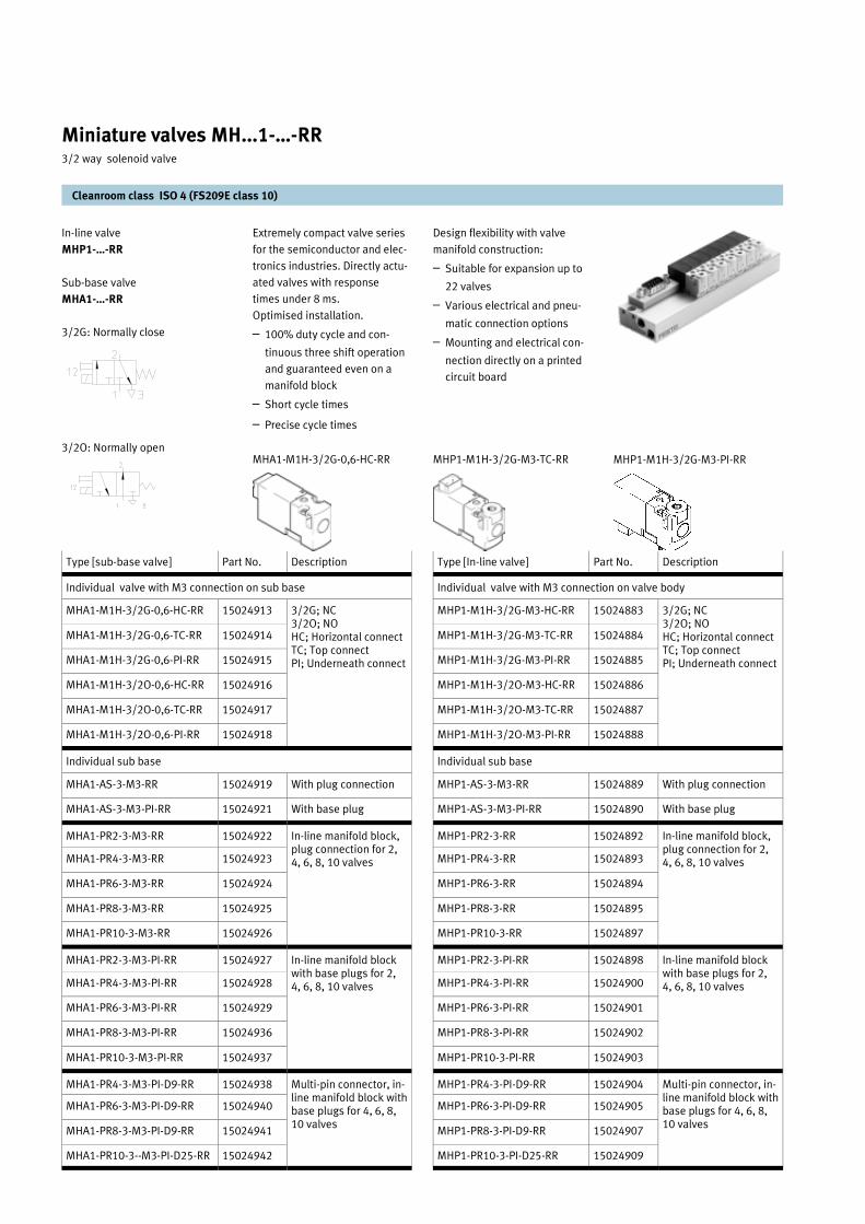
In-line valve
MHP1-…-RR
Sub-base valve
MHA1-…-RR
3/2G: Normally close
3/2O: Normally open MHP1-M1H-3/2G-M3-PI-RR
Extremely compact valve series
for the semiconductor and elec-
tronics industries. Directly actu-
ated valves with response
times under 8 ms.
Optimised installation.
– 100% duty cycle and con-
tinuous three shift operation
and guaranteed even on a
manifold block
– Short cycle times
– Precise cycle times
MHA1-M1H-3/2G-0,6-HC-RR
Design flexibility with valve
manifold construction:
– Suitable for expansion up to
22 valves
– Various electrical and pneu-
matic connection options
– Mounting and electrical con-
nection directly on a printed
circuit board
MHP1-M1H-3/2G-M3-TC-RR
Cleanroom class ISO 4 (FS209E class 10)
Miniature valves MH...1-…-RR 3/2 way solenoid valve
Type [sub-base valve] Part No. Description
Individual valve with M3 connection on sub base
MHA1-M1H-3/2G-0,6-HC-RR 15024913 3/2G; NC 3/2O; NO HC; Horizontal connect TC; Top connect PI; Underneath connect
MHA1-M1H-3/2G-0,6-TC-RR 15024914
MHA1-M1H-3/2G-0,6-PI-RR 15024915
MHA1-M1H-3/2O-0,6-HC-RR 15024916
MHA1-M1H-3/2O-0,6-TC-RR 15024917
MHA1-M1H-3/2O-0,6-PI-RR 15024918
Individual sub base
MHA1-AS-3-M3-RR 15024919 With plug connection
MHA1-AS-3-M3-PI-RR 15024921 With base plug
MHA1-PR2-3-M3-RR 15024922 In-line manifold block, plug connection for 2, 4, 6, 8, 10 valves MHA1-PR4-3-M3-RR 15024923
MHA1-PR6-3-M3-RR 15024924
MHA1-PR8-3-M3-RR 15024925
MHA1-PR10-3-M3-RR 15024926
MHA1-PR2-3-M3-PI-RR 15024927 In-line manifold block with base plugs for 2, 4, 6, 8, 10 valves MHA1-PR4-3-M3-PI-RR 15024928
MHA1-PR6-3-M3-PI-RR 15024929
MHA1-PR8-3-M3-PI-RR 15024936
MHA1-PR10-3-M3-PI-RR 15024937
MHA1-PR4-3-M3-PI-D9-RR 15024938
MHA1-PR6-3-M3-PI-D9-RR 15024940
MHA1-PR8-3-M3-PI-D9-RR 15024941
MHA1-PR10-3--M3-PI-D25-RR 15024942
Multi-pin connector, in-line manifold block with base plugs for 4, 6, 8, 10 valves
Type [In-line valve] Part No. Description
Individual valve with M3 connection on valve body
MHP1-M1H-3/2G-M3-HC-RR 15024883 3/2G; NC 3/2O; NO HC; Horizontal connect TC; Top connect PI; Underneath connect
MHP1-M1H-3/2G-M3-TC-RR 15024884
MHP1-M1H-3/2G-M3-PI-RR 15024885
MHP1-M1H-3/2O-M3-HC-RR 15024886
MHP1-M1H-3/2O-M3-TC-RR 15024887
MHP1-M1H-3/2O-M3-PI-RR 15024888
Individual sub base
MHP1-AS-3-M3-RR 15024889 With plug connection
MHP1-AS-3-M3-PI-RR 15024890 With base plug
MHP1-PR2-3-RR 15024892 In-line manifold block, plug connection for 2, 4, 6, 8, 10 valves MHP1-PR4-3-RR 15024893
MHP1-PR6-3-RR 15024894
MHP1-PR8-3-RR 15024895
MHP1-PR10-3-RR 15024897
MHP1-PR2-3-PI-RR 15024898 In-line manifold block with base plugs for 2, 4, 6, 8, 10 valves MHP1-PR4-3-PI-RR 15024900
MHP1-PR6-3-PI-RR 15024901
MHP1-PR8-3-PI-RR 15024902
MHP1-PR10-3-PI-RR 15024903
MHP1-PR4-3-PI-D9-RR 15024904
MHP1-PR6-3-PI-D9-RR 15024905
MHP1-PR8-3-PI-D9-RR 15024907
MHP1-PR10-3-PI-D25-RR 15024909
Multi-pin connector, in-line manifold block with base plugs for 4, 6, 8, 10 valves

Individual valve with sub base
Sub-base valve (MHA1-…-RR)
Individual sub-base (MHA1-AS-…-RR)
Accessories
In-line valve (MHP1-…)
Individual sub-base (MHP1-AS-…-RR)
Cleanroom class ISO 4 (FS209E class 10)
Miniature valves MH...1-…-RR 3/2 way solenoid valve
Technical data 3/2 way valve
Medium Compressed air, filtered
Nominal flowrate 10 l/min
Design Poppet valve, direct actuated
Width 10 mm
Type of mounting Mounting screw M1.6 x 15
Pneumatic connection
Individual valve 1, 2, 3, 11, 33
M3
Manifold mount 1, 3, 11, 33
M7
2 M3
Nominal size 0.65 mm
Technical data 3/2 way valve
Operating pressure
Normally open 0...6 bar
Normally close 0...8 bar
Response time on/off 4/5 ms
Switching frequency 20 Hz
Temperature range
Individual mount -5…+50°C
Manifold mount -4…+40°C
Material Die-cast zinc
Weight 0.05 kg
Operating voltage 24 V DC ±10%
Power consumption 1W
Duty cycle 100%
Protection class IP 40
Connection type Crimping
Type Part no.
Blanking plug Plug connection MHAP1-BP-3-RR 15024950
Base plug MHAP1-BP-3-PI-RR 15024951
Base plug Plug-in MHAP-PI-RR 15024954
Plug socket with cable
0.5m KMH-0,5-RR 15024955
1.0m KMH-1-RR 15024956
Designation
Base plug MHAP-PI-RR
Plug connection TC
Plug connector HC
Plug connection PI
1
3
4
5
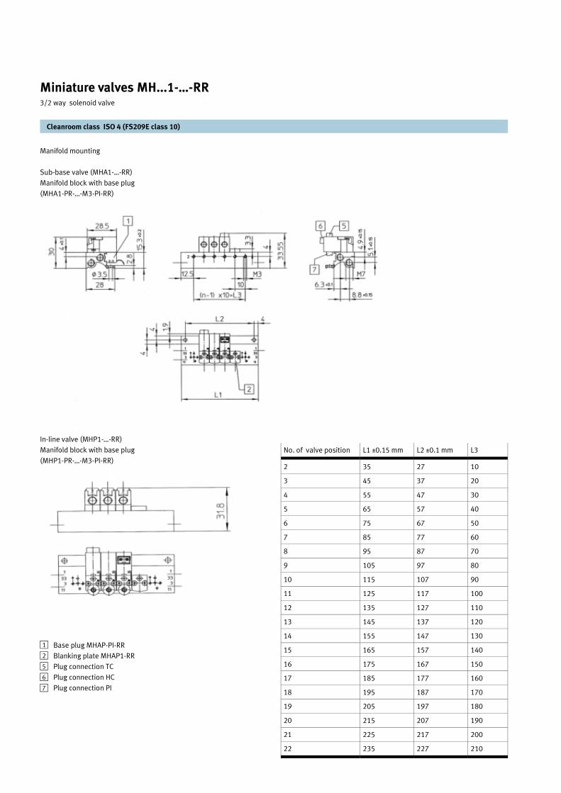
Manifold mounting
Sub-base valve (MHA1-…-RR)
Manifold block with base plug
(MHA1-PR-…-M3-PI-RR)
In-line valve (MHP1-…-RR)
Manifold block with base plug
(MHP1-PR-…-M3-PI-RR)
Cleanroom class ISO 4 (FS209E class 10)
Miniature valves MH...1-…-RR 3/2 way solenoid valve
No. of valve position L1 ±0.15 mm L2 ±0.1 mm L3
2 35 27 10
3 45 37 20
4 55 47 30
5 65 57 40
6 75 67 50
7 85 77 60
8 95 87 70
9 105 97 80
10 115 107 90
11 125 117 100
12 135 127 110
13 145 137 120
14 155 147 130
15 165 157 140
16 175 167 150
17 185 177 160
18 195 187 170
19 205 197 180
20 215 207 190
21 225 217 200
22 235 227 210
Base plug MHAP-PI-RR
Blanking plate MHAP1-RR
Plug connection TC
Plug connection HC
Plug connection PI
12
5
6
7

Manifold mounting
Sub-base valve (MHA1-…-RR)
Multi-pin, manifold block with base
plug (MHA1-PR-…-M3-PI-D9-RR)
In-line valve (MHP1-…-RR)
Multi-pin manifold block with base
plug (MHP1-PR-…-M3-PI-D9-RR)
Cleanroom class ISO 4 (FS209E class 10)
Miniature valves MH...1-…-RR 3/2 way solenoid valve
No. of valve position L1 ±0.1 mm L2 ±0.15 mm L3
2 70 63 10
4 90 83 30
6 110 103 50
8 130 123 70
10 172 165 90
12 192 185 110
14 212 205 130
16 232 225 150
18 252 245 170
20 272 265 190
22 292 285 210
Base plug MHAP-PI-RR
Sub-D plug 9/25 pins
Blanking plate MHAP1-RR
12
3
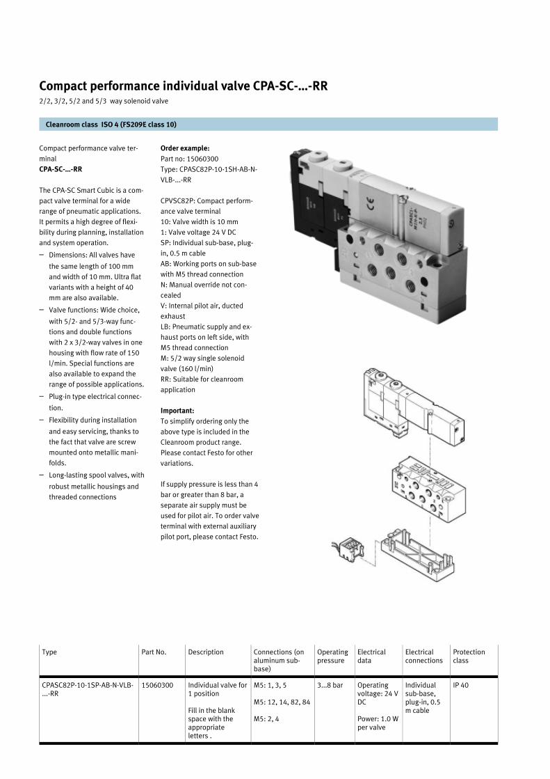
Compact performance valve ter-
minal
CPA-SC-…-RR
The CPA-SC Smart Cubic is a com-
pact valve terminal for a wide
range of pneumatic applications.
It permits a high degree of flexi-
bility during planning, installation
and system operation.
– Dimensions: All valves have
the same length of 100 mm
and width of 10 mm. Ultra flat
variants with a height of 40
mm are also available.
– Valve functions: Wide choice,
with 5/2- and 5/3-way func-
tions and double functions
with 2 x 3/2-way valves in one
housing with flow rate of 150
l/min. Special functions are
also available to expand the
range of possible applications.
– Plug-in type electrical connec-
tion.
– Flexibility during installation
and easy servicing, thanks to
the fact that valve are screw
mounted onto metallic mani-
folds.
– Long-lasting spool valves, with
robust metallic housings and
threaded connections
Cleanroom class ISO 4 (FS209E class 10)
Compact performance individual valve CPA-SC-…-RR 2/2, 3/2, 5/2 and 5/3 way solenoid valve
Type Part No. Description Connections (on aluminum sub-base)
Operating pressure
Electrical data
Electrical connections
Protection class
CPASC82P-10-1SP-AB-N-VLB- ...-RR
15060300 M5: 1, 3, 5
M5: 12, 14, 82, 84
M5: 2, 4
3...8 bar Operating voltage: 24 V DC
Power: 1.0 W per valve
Individual sub-base, plug-in, 0.5 m cable
IP 40 Individual valve for 1 position
Fill in the blank space with the appropriate letters .
Order example:
Part no: 15060300
Type: CPASC82P-10-1SH-AB-N-
VLB-...-RR
CPVSC82P: Compact perform-
ance valve terminal
10: Valve width is 10 mm
1: Valve voltage 24 V DC
SP: Individual sub-base, plug-
in, 0.5 m cable
AB: Working ports on sub-base
with M5 thread connection
N: Manual override not con-
cealed
V: Internal pilot air, ducted
exhaust
LB: Pneumatic supply and ex-
haust ports on left side, with
M5 thread connection
M: 5/2 way single solenoid
valve (160 l/min)
RR: Suitable for cleanroom
application
Important:
To simplify ordering only the
above type is included in the
Cleanroom product range.
Please contact Festo for other
variations.
If supply pressure is less than 4
bar or greater than 8 bar, a
separate air supply must be
used for pilot air. To order valve
terminal with external auxiliary
pilot port, please contact Festo.

Cleanroom class ISO 4 (FS209E class 10)
Compact performance individual valve CPA-SC-…-RR 2/2, 3/2, 5/2 and 5/3 way solenoid valve
The CPA-SC offers the following
valve options. When ordering,
fill in the blank space with the
appropriate letters:
B: 5/3 way mid position pres-
surised valve (160 l/min)
E: 5/3 way mid position ex-
hausted valve (160 l/min)
M: 5/2 way single solenoid
valve (160 l/min)
N: 2 x 3/2 way valve normally
open (140 l/min)
X: 1 x 3/2 way valve, external
compressed air supply, nor-
mally closed (100 l/min)
G: 5/3 way mid position closed
valve (140 l/min)
I: 2 x 2/2 way valve, normally
close, for vacuum (140 l/min)
J: 5/2 way double solenoid
valve (160 l/min)
K: 2 x 3/2 way valve normally
close (140 l/min)
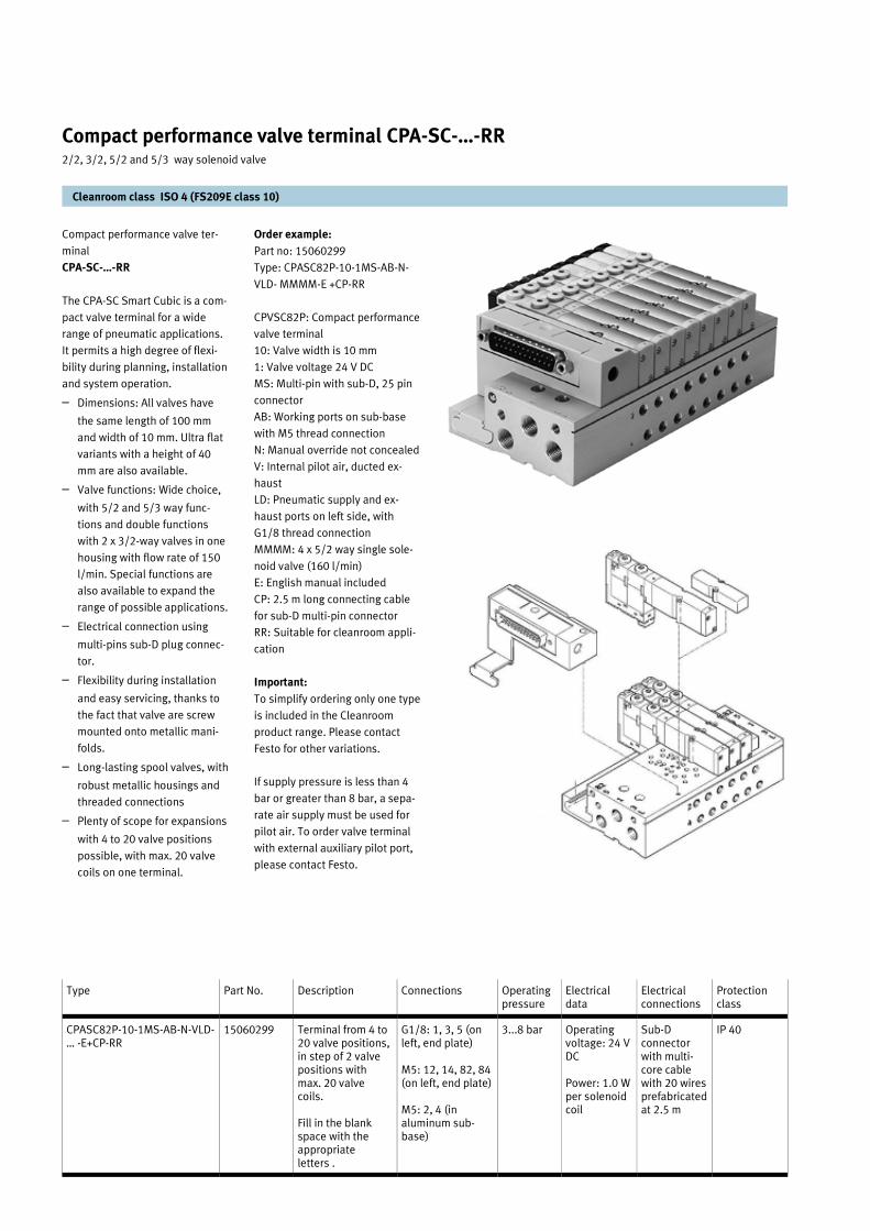
Compact performance valve ter-
minal
CPA-SC-…-RR
The CPA-SC Smart Cubic is a com-
pact valve terminal for a wide
range of pneumatic applications.
It permits a high degree of flexi-
bility during planning, installation
and system operation.
– Dimensions: All valves have
the same length of 100 mm
and width of 10 mm. Ultra flat
variants with a height of 40
mm are also available.
– Valve functions: Wide choice,
with 5/2 and 5/3 way func-
tions and double functions
with 2 x 3/2-way valves in one
housing with flow rate of 150
l/min. Special functions are
also available to expand the
range of possible applications.
– Electrical connection using
multi-pins sub-D plug connec-
tor.
– Flexibility during installation
and easy servicing, thanks to
the fact that valve are screw
mounted onto metallic mani-
folds.
– Long-lasting spool valves, with
robust metallic housings and
threaded connections
– Plenty of scope for expansions
with 4 to 20 valve positions
possible, with max. 20 valve
coils on one terminal.
Cleanroom class ISO 4 (FS209E class 10)
Compact performance valve terminal CPA-SC-…-RR 2/2, 3/2, 5/2 and 5/3 way solenoid valve
Type Part No. Description Connections Operating pressure
Electrical data
Electrical connections
Protection class
CPASC82P-10-1MS-AB-N-VLD- … -E+CP-RR
15060299 G1/8: 1, 3, 5 (on left, end plate)
M5: 12, 14, 82, 84 (on left, end plate)
M5: 2, 4 (in aluminum sub-base)
3...8 bar Operating voltage: 24 V DC
Power: 1.0 W per solenoid coil
Sub-D connector with multi-core cable with 20 wires prefabricated at 2.5 m
IP 40 Terminal from 4 to 20 valve positions, in step of 2 valve positions with max. 20 valve coils.
Fill in the blank space with the appropriate letters .
Order example:
Part no: 15060299
Type: CPASC82P-10-1MS-AB-N-
VLD- MMMM-E +CP-RR
CPVSC82P: Compact performance
valve terminal
10: Valve width is 10 mm
1: Valve voltage 24 V DC
MS: Multi-pin with sub-D, 25 pin
connector
AB: Working ports on sub-base
with M5 thread connection
N: Manual override not concealed
V: Internal pilot air, ducted ex-
haust
LD: Pneumatic supply and ex-
haust ports on left side, with
G1/8 thread connection
MMMM: 4 x 5/2 way single sole-
noid valve (160 l/min)
E: English manual included
CP: 2.5 m long connecting cable
for sub-D multi-pin connector
RR: Suitable for cleanroom appli-
cation
Important:
To simplify ordering only one type
is included in the Cleanroom
product range. Please contact
Festo for other variations.
If supply pressure is less than 4
bar or greater than 8 bar, a sepa-
rate air supply must be used for
pilot air. To order valve terminal
with external auxiliary pilot port,
please contact Festo.
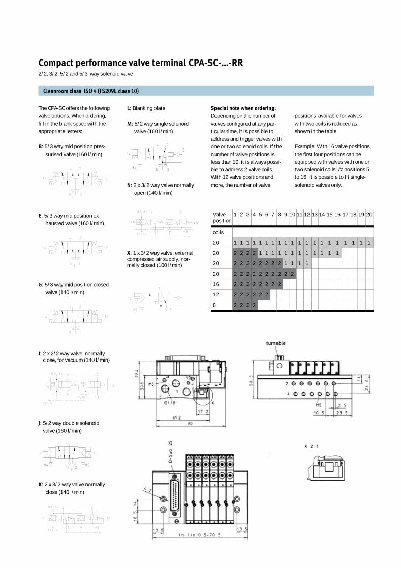
Cleanroom class ISO 4 (FS209E class 10)
Compact performance valve terminal CPA-SC-…-RR 2/2, 3/2, 5/2 and 5/3 way solenoid valve
The CPA-SC offers the following valve options. When ordering, fill in the blank space with the appropriate letters:
B: 5/3 way mid position pres-surised valve (160 l/min)
E: 5/3 way mid position ex-hausted valve (160 l/min)
G: 5/3 way mid position closed valve (140 l/min)
I: 2 x 2/2 way valve, normally close, for vacuum (140 l/min)
J: 5/2 way double solenoid valve (160 l/min)
K: 2 x 3/2 way valve normally close (140 l/min)
positions available for valves with two coils is reduced as shown in the table
Example: With 16 valve positions, the first four positions can be equipped with valves with one or two solenoid coils. At positions 5 to 16, it is possible to fit single-solenoid valves only.
L: Blanking plate
M: 5/2 way single solenoid valve (160 l/min)
N: 2 x 3/2 way valve normally open (140 l/min)
X: 1 x 3/2 way valve, external compressed air supply, nor-mally closed (100 l/min)
Special note when ordering:
Depending on the number of valves configured at any par-ticular time, it is possible to address and trigger valves with one or two solenoid coils. If the number of valve positions is less than 10, it is always possi-ble to address 2 valve coils. With 12 valve positions and more, the number of valve
Valve position
1 2 3 4 5 6 7 8 9 10 11 12 13 14 15 16 17 18 19 20
coils
20 1 1 1 1 1 1 1 1 1 1 1 1 1 1 1 1 1 1 1 1
20 2 2 2 2 1 1 1 1 1 1 1 1 1 1 1 1
20 2 2 2 2 2 2 2 2 1 1 1 1
20 2 2 2 2 2 2 2 2 2 2
16 2 2 2 2 2 2 2 2
12 2 2 2 2 2 2
8 2 2 2 2

Order example:
Part no: 15059882
Type: CDVI15P-K05-4G-UR-
MMMM-E-Y-RR
CDVI15P: Clean design valve
terminal
K05: Multi-core cable of 5 m
4G: 4 positions with G1/8
pneumatic connections
U: Supply on left side, internal
pilot air supply
R: Resistant to cleaning agents
MMMM: 4 x 5/2 way single
solenoid valve (650 l/min)
E: English manual included
Y: 4 x spacing bolt included
RR: Suitable for cleanroom
application
Important:
To simplify ordering only one
type is included in the Clean-
room product range. Please
contact Festo for other varia-
tions.
If supply pressure is less than 4
bar or greater than 6 bar, a
separate air supply must be
used for pilot air. To order valve
terminal with external auxiliary
pilot port, please contact Festo.
Clean design valve terminal
CDVI15P-…-RR
The basic version of the CDVI
valve terminal is available with
4 or 8 positions. Contrary to
the standard non-cleanroom
version, the cleanroom version
cannot be expanded with 2
position modules for additional
positions.
– Easy to clean as a result of
no shape edges, no small
radius and no corners where
dirt can be trapped
– Ample space between valves
to allow for laminar air flow
– Corrosion resistant material
– The terminals include com-
mon supply lines and ex-
haust for all valves
– The electrical bus lines are
connected to the end plate
– Protection class IP65 and
IP67
Material:
Housing: Polypropylene (PP)
Seal: EPDM
Subbase: Aluminum anodised
Cable: PVC (Chemical resistant)
Cleanroom class ISO 4 (FS209E class 10)
Clean design valve terminal CDVI15P-…-RR 3/2, 5/2 and 5/3 way solenoid valve
Type Part No. Description Connections Operating pressure
Electrical data
Electrical connections
Mounting
CDVI15P-K05-4G-UR-…-E-Y-RR 15059882 Terminal for 4 valves positions .
Fill in the blank space with 4 appropriate letters.
G3/8: 1, 3, 5 (in end plate)
G1/8: 12, 14, 82, 84 (in end plate)
G1/8: 2, 4 (in aluminum profile)
3...6 bar Operating voltage: 24 V DC
Power: 1.5 W per valve; holding current reduced to 50% after 20 ms.
Multi-core cable with 26 wires prefabricated at 5 m
CDVI15P-K05-8G-UR-...-E-Y-RR 15060242 Terminal for 8 valves positions.
Fill in the blank space with 8 appropriate letters.
Mounting with 2 screw at end plate or use spacer both provided
Mounting:
With spacer bolt provided

Cleanroom class ISO 4 (FS209E class 10)
Clean design valve terminal CDVI15P-…-RR 3/2, 5/2 and 5/3 way solenoid valve
The CDVI offers the following
valve combination options.
When ordering, fill in the blank
space with the appropriate
letters:
A: Blanking plate for double
positions
B: 5/3 way mid position pres-
surised valve (500 l/min)
C: Blanking plate for single
position
E: 5/3 way mid position ex-
hausted valve (400 l/min)
G: 5/3 way mid position closed
valve (600 l/min)
H: 2 x 3/2 way valve, 1 nor-
mally open and 1 normally
close (300 l/min)
J: 5/2 way double solenoid
valve (650 l/min)
K: 2 x 3/2 way valve normally
close (300 l/min)
M: 5/2 way single solenoid
valve (650 l/min)
N: 2 x 3/2 way valve normally
open (300 l/min)
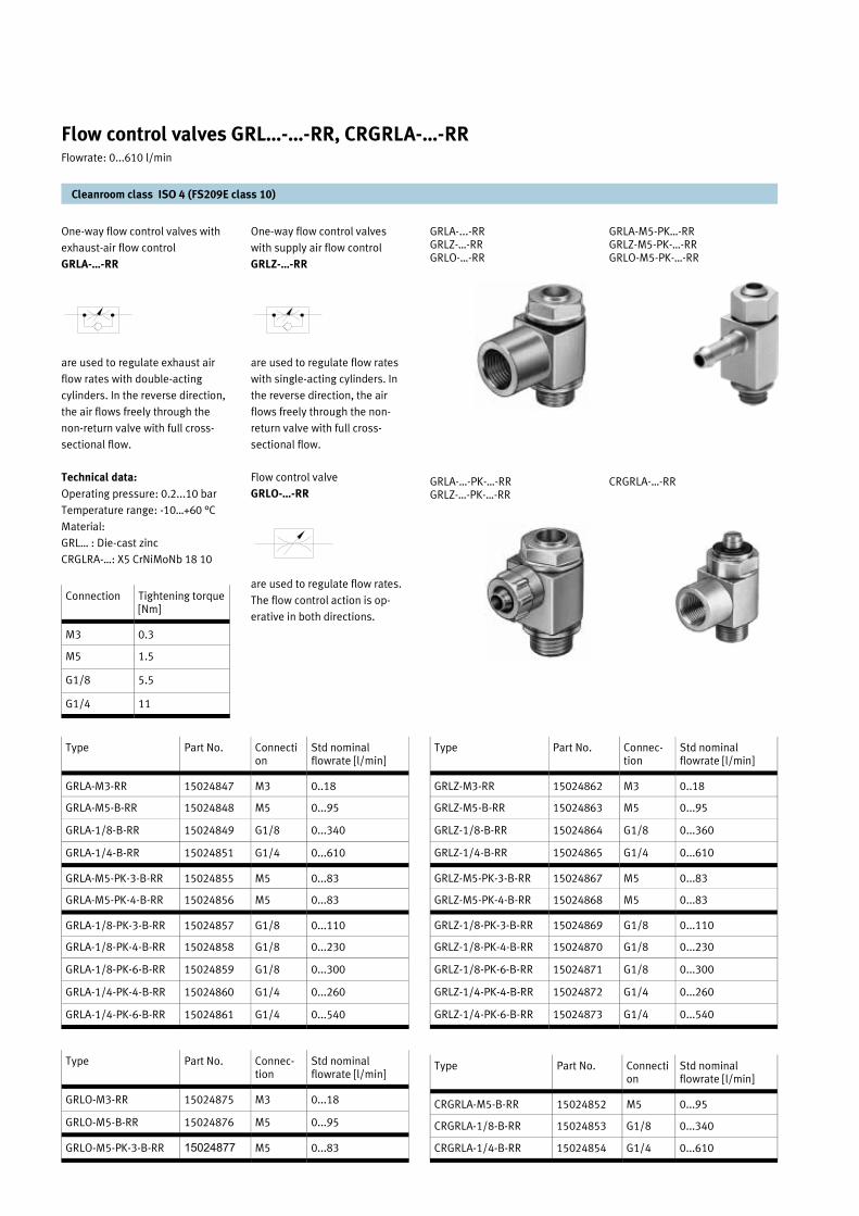
One-way flow control valves with
exhaust-air flow control
GRLA-…-RR
are used to regulate exhaust air
flow rates with double-acting
cylinders. In the reverse direction,
the air flows freely through the
non-return valve with full cross-
sectional flow.
Technical data:
Operating pressure: 0.2...10 bar
Temperature range: -10…+60 °C
Material:
GRL… : Die-cast zinc
CRGLRA-…: X5 CrNiMoNb 18 10
GRLA-M5-PK…-RR GRLZ-M5-PK-…-RR GRLO-M5-PK-…-RR
CRGRLA-…-RR
One-way flow control valves
with supply air flow control
GRLZ-…-RR
are used to regulate flow rates
with single-acting cylinders. In
the reverse direction, the air
flows freely through the non-
return valve with full cross-
sectional flow.
Flow control valve
GRLO-…-RR
are used to regulate flow rates.
The flow control action is op-
erative in both directions.
GRLA-...-RR GRLZ-…-RR GRLO-…-RR
GRLA-…-PK-…-RR GRLZ-…-PK-…-RR
Cleanroom class ISO 4 (FS209E class 10)
Flow control valves GRL…-…-RR, CRGRLA-…-RR Flowrate: 0...610 l/min
Type Part No. Connec-tion
Std nominal flowrate [l/min]
GRLZ-M3-RR 15024862 M3 0..18
GRLZ-M5-B-RR 15024863 M5 0...95
GRLZ-1/8-B-RR 15024864 G1/8 0...360
GRLZ-1/4-B-RR 15024865 G1/4 0...610
GRLZ-M5-PK-3-B-RR 15024867 M5 0...83
GRLZ-M5-PK-4-B-RR 15024868 M5 0...83
GRLZ-1/8-PK-3-B-RR 15024869 G1/8 0...110
GRLZ-1/8-PK-4-B-RR 15024870 G1/8 0...230
GRLZ-1/8-PK-6-B-RR 15024871 G1/8 0...300
GRLZ-1/4-PK-4-B-RR 15024872 G1/4 0...260
GRLZ-1/4-PK-6-B-RR 15024873 G1/4 0...540
Type Part No. Connec-tion
Std nominal flowrate [l/min]
GRLO-M3-RR 15024875 M3 0...18
GRLO-M5-B-RR 15024876 M5 0...95
GRLO-M5-PK-3-B-RR 15024877 M5 0...83
Type Part No. Connection
Std nominal flowrate [l/min]
GRLA-M3-RR 15024847 M3 0..18
GRLA-M5-B-RR 15024848 M5 0...95
GRLA-1/8-B-RR 15024849 G1/8 0...340
GRLA-1/4-B-RR 15024851 G1/4 0...610
GRLA-M5-PK-3-B-RR 15024855 M5 0...83
GRLA-M5-PK-4-B-RR 15024856 M5 0...83
GRLA-1/8-PK-3-B-RR 15024857 G1/8 0...110
GRLA-1/8-PK-4-B-RR 15024858 G1/8 0...230
GRLA-1/8-PK-6-B-RR 15024859 G1/8 0...300
GRLA-1/4-PK-4-B-RR 15024860 G1/4 0...260
GRLA-1/4-PK-6-B-RR 15024861 G1/4 0...540
Type Part No. Connection
Std nominal flowrate [l/min]
CRGRLA-M5-B-RR 15024852 M5 0...95
CRGRLA-1/8-B-RR 15024853 G1/8 0...340
CRGRLA-1/4-B-RR 15024854 G1/4 0...610
Connection Tightening torque [Nm]
M3 0.3
M5 1.5
G1/8 5.5
G1/4 11

GRLA-...-RR GRLZ-…-RR GRLO-…-RR
GRLA-…-PK-…-RR GRLZ-…-PK-…-RR
GRLA-M5-PK…-RR GRLZ-M5-PK-…-RR GRLO-M5-PK-…-RR
CRGRLA-…-RR
Cleanroom class ISO 4 (FS209E class 10)
Flow control valves GR…-…-RR, CRGRLA-…-RR Flowrate: 0...610 l/min
Type B D H H1 L L1 L2 ß
GRL...-M3-RR 5 M3 9 6.5 13.3 2.5 6.4 4.5
GRL...-M5-B-RR 10 M5 17.5 12.5 17.6 4 7.1 9
GRL...-1/8-B-RR 16 G 28 20 25.2 5.3 10.3 14
GRL...-1/4-B-RR 20 G 36 26 30.8 8.2 13.2 17
Type B D H H1 L L1 L2 ß
GRL...-M5-PK-3-B-RR
10 M5 19.7 14.7 17.6 4 8.5 9
GRL...-M5-PK-4-B-RR
10 M5 21.7 16.7 17.6 4 8.5 9
Type B D H H1 L L1 L2 ß
GRL...-1/8-PK-3-B-RR
16 G1/8 27.1 19.1 25.2 5.3 13.4 14
GRL...-1/8-PK-4-B-RR
16 G1/8 30.2 22.2 25.2 5.3 13.4 14
GRL...-1/8-PK-6-B-RR
16 G1/8 30.3 22.3 25.2 5.3 12 14
GRL...-1/4-PK-4-B-RR
20 G1/4 34.2 24.2 30.8 8.2 16.9 17
GRL...-1/4-PK-6-B-RR
20 G1/4 34.3 24.3 30.8 8.2 17.2 17
Type B D H H1 L L1 L2 L3 ß
CRGRLA-M5-B-RR
10 M5 17.5 12.5 23.2 4 7.1 2.5 9
CRGRLA-1/8-B-RR
16 G1/8 28 20 33.7 5.3 10.3 3.5 14
CRGRLA-1/4-B-RR
20 G1/4 36 26 38.8 8.3 13.2 3.5 17

Cleanroom class ISO 4 (FS209E class 10)
One way flow control valve
GR-…-RR
GR-M3-RR
GR-1/8-B-RR
These valves are used to regu-
late air flow, e.g. to control the
piston speeds of single and
double-acting cylinders, or as a
flow control valve for back pres-
sure nozzles.. A non-return
valve blocks air flow in one
direction. Air is only able to
flow via the cross section which
is adjusted with the throttle
screw. Air flows freely in the
other direction through the
open non-return valve.
– Tamper-proof cap for secur-
ing against inadvertent read-
justment
– Hex nut for panel mounting
– Precision thread for accurate
flow rate adjustment
GR-M5-B-RR
GRA-1/4-B-RR
Flow control valves GR-…-RR Flowrate: 0...420 l/min
Type Part No. Connec-tion
Nominal size [mm]
Std nominal flowrate [l/min]
Full flow [l/min]
Pressure range [bar]
Temperature range [°C]
Material Weight [kg]
GR-M3-RR 15024878 M3 1 0...29 - 0.3...8 -10…+60 Al 0.002
GR-M5-B-RR 15024879 M5 2 0...94 115 0.5...10 -20…+60 Al 0.020
GR-1/8-B-RR 15024880 G1/8 3 0...220 217 0.5...10 -20…+60 Al 0.035
GRA-1/4-B-RR 15024881 G1/4 4.5 0...420 780 0.1...10 -20…+75 ZnAl, brass 0.180
1 Tamper-proof cap
2 Hex nut for panel mount

Air Preparation units and accessories

Filter 5.0 µm with manual con-
densate drain
LF-…-D-5M-MICRO-RR
– Sintered filter with condensate
separator
– Vertical mounting position, ±5°
– Good particle and condensate
separation
– High flow rate with minimal
pressure drop
– 5 µm filter cartridges
Cleanroom class ISO 4 (FS209E class 10)
Filter for D-Micro series LF-…-D-M5-MICRO-RR Flowrate: 170...290 l/min
Type Part No. Connection Std nominal flowrate at 7 bar
Weight Input pressure
Temperature range
Condensate volume
[5.0 µm] [l/min] [kg] [bar] [°C] [ml]
LF-M5-D-5M-MICRO-RR 15059897 M5 (Thread screw in housing)
170 0.044 0...10 -10…+60 3
LF-M7-D-5M-MICRO-RR 15059898 M7 (Thread in connection plate)
280 0.064
LF-1/8-D-5M-MICRO-RR 15059899 G1/8 (Thread in connection plate)
290 0.064
LF-M5-D-M5-MICRO-RR
LF-M7-D-M5-MICRO-RR
LF-1/8-D-M5-MICRO-RR
Accessories
Mounting bracket
HFOE-D-MICRO
Connecting plate kit
PBL-M7-D-MICRO
PBL-1/8-D-MICRO
Threaded pin set
FRB-D-MICRO
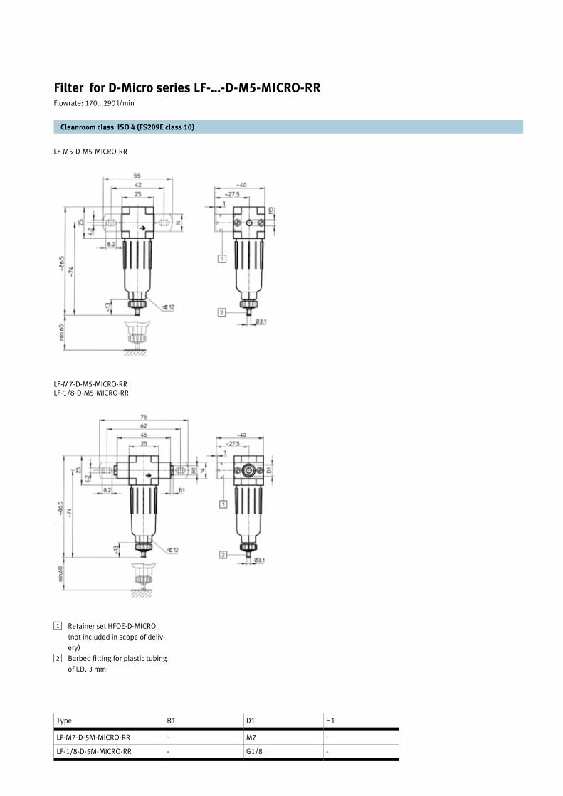
LF-M5-D-M5-MICRO-RR
LF-M7-D-M5-MICRO-RR LF-1/8-D-M5-MICRO-RR
Type B1 D1 H1
LF-M7-D-5M-MICRO-RR - M7 -
LF-1/8-D-5M-MICRO-RR - G1/8 -
Filter for D-Micro series LF-…-D-M5-MICRO-RR Flowrate: 170...290 l/min
Retainer set HFOE-D-MICRO
(not included in scope of deliv-
ery)
Barbed fitting for plastic tubing
of I.D. 3 mm
1
2
Cleanroom class ISO 4 (FS209E class 10)

Micro filter 0.01 µm with manual
condensate drain
LFMA-…-D-…-RR
Micro filter 1 µm with manual
condensate drain
LFMB-…-D-…-RR
– High efficiency filter for special
requirements
– Optional filter cartridges 1 µm
or 0.01 µm
– Air quality to ISO 8573-1
– Available as pre-assembled
filter combination
– Optional manual condensate
drain, or integrated, automatic
condensate drain Sate
– Operating pressure; 1...16 bar
– Temperature range; -10…+60°C
– Mounting position; Vertical ±5°
– Filter housing of die-cast zinc
or aluminium
LFMA:
ISO class 1: for particles
ISO class 2: for oil aerosols
Residual oil content 0.01 mg/m³
Filter efficiency 99.9999 %
LFMB:
ISO class 2: for particles
ISO class 3: for oil aerosols
Residual oil content 0.5 mg/m³
Filter efficiency 99.99 %
Characteristic curve for flow
rate
LFMB-1/4-D-MINI
LFMB-1/2-D-MIDI
LFMB-1-D-MAXI
Characteristic curve for flow
rate
LFMA-1/4-D-MINI
LFMA-1/2-D-MIDI
LFMA-1-D-MAXI
Microfilter LFMA-…-RR and LFMB-…-RR Flowrate: 130...1250 l/min
Type Part No. Connec-tion
Std nominal flowrate
Type Part No. Connec-tion
Std nominal flowrate
Condensate volume
Weight
[0.01 µm] [l/min] [1 µm] [l/min] [ml] [kg]
LFMA-1/8-D-MINI-RR 15024732 G1/8 130 LFMB-1/8-D-MINI-RR 15024743 G1/8 250 22 0.250
LFMA-1/4-D-MINI-RR 15024733 G1/4 160 LFMB-1/4-D-MINI-RR 15024744 G1/4 300
LFMA-3/8-D-MINI-RR 15024734 G3/8 180 LFMB-3/8-D-MINI-RR 15024748 G3/8 310
LFMA-1/4-D-MIDI-RR 15024735 G1/4 350 LFMB-1/4-D-MIDI-RR 15024749 G1/4 500 43 0.650
LFMA-3/8-D-MIDI-RR 15024736 G3/8 380 LFMB-3/8-D-MIDI-RR 15024750 G3/8 700
LFMA-1/2-D-MIDI-RR 15024737 G1/2 400 LFMB-1/2-D-MIDI-RR 15024752 G1/2 900
LFMA-3/4-D-MIDI-RR 15024739 G3/4 460 LFMB-3/4-D-MIDI-RR 15024754 G3/4 1000
LFMA-1/2-D-MAXI-RR 15024740 G1/2 750 LFMB-1/2-D-MAXI-RR 15024755 G1/2 1150 80 1.2
LFMA-3/4-D-MAXI-RR 15024741 G3/4 900 LFMB-3/4-D-MAXI-RR 15024756 G3/4 1200
LFMA-1-D-MAXI-RR 15024742 G1 950 LFMB-1-D-MAXI-RR 15024757 G1 1250
Standard flow rate Standard flow rate
Standard flow rate Standard flow rate
Standard flow rate Standard flow rate
Dif
fere
nti
al
pre
ssu
re
Dif
fere
nti
al
pre
ssu
re
Dif
fere
nti
al
pre
ssu
re
Dif
fere
nti
al p
ress
ure
Dif
fere
nti
al p
ress
ure
Dif
fere
nti
al p
ress
ure
Cleanroom class ISO 4 (FS209E class 10)
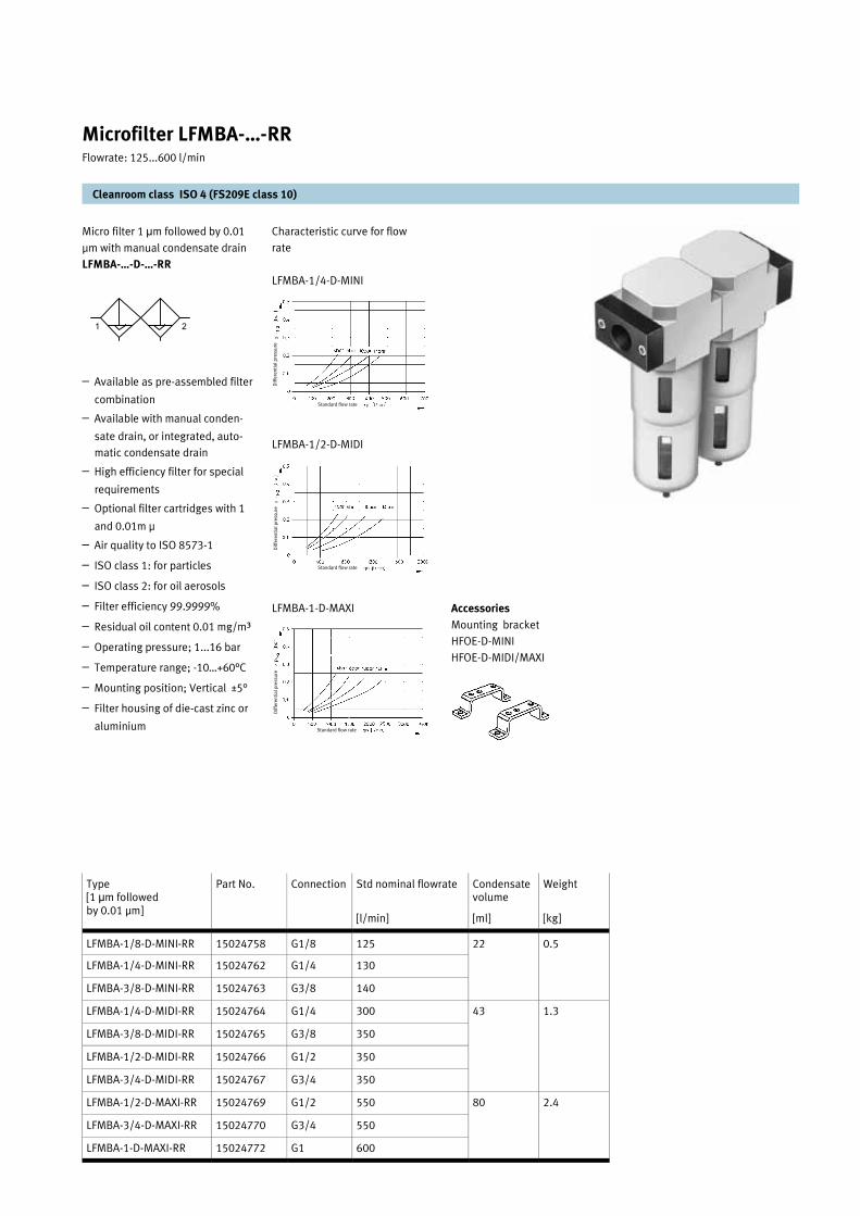
Micro filter 1 µm followed by 0.01
µm with manual condensate drain
LFMBA-…-D-…-RR
– Available as pre-assembled filter
combination
– Available with manual conden-
sate drain, or integrated, auto-
matic condensate drain
– High efficiency filter for special
requirements
– Optional filter cartridges with 1
and 0.01m µ
– Air quality to ISO 8573-1
– ISO class 1: for particles
– ISO class 2: for oil aerosols
– Filter efficiency 99.9999%
– Residual oil content 0.01 mg/m³
– Operating pressure; 1...16 bar
– Temperature range; -10…+60°C
– Mounting position; Vertical ±5°
– Filter housing of die-cast zinc or
aluminium
Characteristic curve for flow
rate
LFMBA-1/4-D-MINI
LFMBA-1/2-D-MIDI
LFMBA-1-D-MAXI
Cleanroom class ISO 4 (FS209E class 10)
Microfilter LFMBA-…-RR Flowrate: 125...600 l/min
Type [1 µm followed by 0.01 µm]
Part No. Connection Std nominal flowrate Condensate volume
Weight
[l/min] [ml] [kg]
LFMBA-1/8-D-MINI-RR 15024758 G1/8 125 22 0.5
LFMBA-1/4-D-MINI-RR 15024762 G1/4 130
LFMBA-3/8-D-MINI-RR 15024763 G3/8 140
LFMBA-1/4-D-MIDI-RR 15024764 G1/4 300 43 1.3
LFMBA-3/8-D-MIDI-RR 15024765 G3/8 350
LFMBA-1/2-D-MIDI-RR 15024766 G1/2 350
LFMBA-3/4-D-MIDI-RR 15024767 G3/4 350
LFMBA-1/2-D-MAXI-RR 15024769 G1/2 550 80 2.4
LFMBA-3/4-D-MAXI-RR 15024770 G3/4 550
LFMBA-1-D-MAXI-RR 15024772 G1 600
1 2
Standard flow rate
Standard flow rate
Standard flow rate
Dif
fere
nti
al
pre
ssu
re
Dif
fere
nti
al p
ress
ure
D
iffe
ren
tia
l p
ress
ure
Accessories
Mounting bracket
HFOE-D-MINI
HFOE-D-MIDI/MAXI
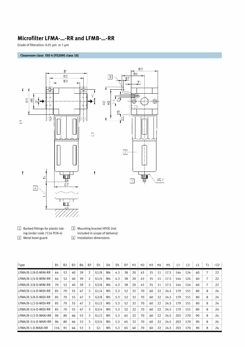
Cleanroom class ISO 4 (FS209E class 10)
Microfilter LFMA-…-RR and LFMB-…-RR Grade of filteration: 0.01 µm or 1 µm
Type B1 B2 B3 B6 B7 D1 D4 D5 D7 H1 H2 H3 H4 H5 L1 L3 L5 T1 ß2
LFMA/B-1/8-D-MINI-RR 64 52 40 39 2 G1/8 M4 4.3 38 20 43 35 11 17.5 144 124 60 7 22
LFMA/B-1/4-D-MINI-RR 64 52 40 39 2 G1/4 M4 4.3 38 20 43 35 11 17.5 144 124 60 7 22
LFMA/B-3/8-D-MINI-RR 70 52 40 39 2 G3/8 M4 4.3 38 20 43 35 11 17.5 144 124 60 7 22
LFMA/B-1/4-D-MIDI-RR 85 70 55 47 3 G1/4 M5 5.3 52 32 70 60 22 24.5 179 151 80 8 24
LFMA/B-3/8-D-MIDI-RR 85 70 55 47 3 G3/8 M5 5.3 52 32 70 60 22 24.5 179 151 80 8 24
LFMA/B-1/2-D-MIDI-RR 85 70 55 47 3 G1/2 M5 5.3 52 32 70 60 22 24.5 179 151 80 8 24
LFMA/B-3/4-D-MIDI-RR 85 70 55 47 3 G3/4 M5 5.3 52 32 70 60 22 24.5 179 151 80 8 24
LFMA/B-1/2-D-MAXI-RR 96 80 66 53 3 G1/2 M5 5.3 65 32 70 60 22 24.5 203 170 90 8 24
LFMA/B-3/4-D-MAXI-RR 96 80 66 53 3 G3/4 M5 5.3 65 32 70 60 22 24.5 203 170 90 8 24
LFMA/B-1-D-MAXI-RR 116 91 66 53 3 G1 M5 5.3 65 40 70 60 22 24.5 203 170 90 8 24
1
2
Barbed fittings for plastic tub-
ing (order code 7134 PCN-4)
Metal bowl guard
Mounting bracket HFOE (not
included in scope of delivery)
Installation dimensions
3
4
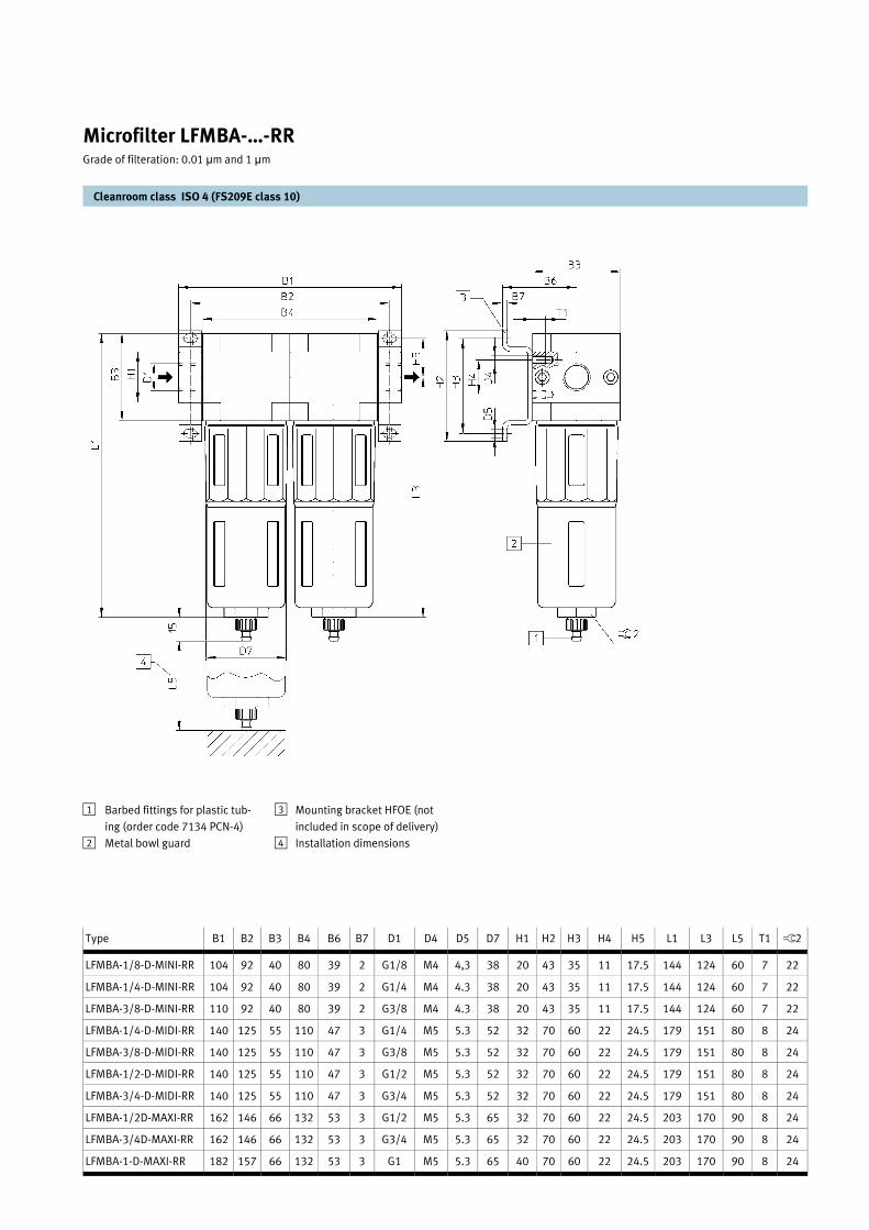
Cleanroom class ISO 4 (FS209E class 10)
Microfilter LFMBA-…-RR Grade of filteration: 0.01 µm and 1 µm
Type B1 B2 B3 B4 B6 B7 D1 D4 D5 D7 H1 H2 H3 H4 H5 L1 L3 L5 T1 ß2
LFMBA-1/8-D-MINI-RR 104 92 40 80 39 2 G1/8 M4 4,3 38 20 43 35 11 17.5 144 124 60 7 22
LFMBA-1/4-D-MINI-RR 104 92 40 80 39 2 G1/4 M4 4.3 38 20 43 35 11 17.5 144 124 60 7 22
LFMBA-3/8-D-MINI-RR 110 92 40 80 39 2 G3/8 M4 4.3 38 20 43 35 11 17.5 144 124 60 7 22
LFMBA-1/4-D-MIDI-RR 140 125 55 110 47 3 G1/4 M5 5.3 52 32 70 60 22 24.5 179 151 80 8 24
LFMBA-3/8-D-MIDI-RR 140 125 55 110 47 3 G3/8 M5 5.3 52 32 70 60 22 24.5 179 151 80 8 24
LFMBA-1/2-D-MIDI-RR 140 125 55 110 47 3 G1/2 M5 5.3 52 32 70 60 22 24.5 179 151 80 8 24
LFMBA-3/4-D-MIDI-RR 140 125 55 110 47 3 G3/4 M5 5.3 52 32 70 60 22 24.5 179 151 80 8 24
LFMBA-1/2D-MAXI-RR 162 146 66 132 53 3 G1/2 M5 5.3 65 32 70 60 22 24.5 203 170 90 8 24
LFMBA-3/4D-MAXI-RR 162 146 66 132 53 3 G3/4 M5 5.3 65 32 70 60 22 24.5 203 170 90 8 24
LFMBA-1-D-MAXI-RR 182 157 66 132 53 3 G1 M5 5.3 65 40 70 60 22 24.5 203 170 90 8 24
Barbed fittings for plastic tub-
ing (order code 7134 PCN-4)
Metal bowl guard
1
2
Mounting bracket HFOE (not
included in scope of delivery)
Installation dimensions
3
4

– The valve can be combined with
service units of series D
– Input pressure; 0...16 bar
– Temperature range; -10...+60 °C
– Material; Die-cast zinc / alumin-
ium
Accessories
Mounting bracket
HFOE-D-MINI
HFOE-D-MIDI/MAXI
Manual on/off valve with
threaded connection plate
HE-...-D-…-RR
– 3/2-way manual non-return
valve
– The system is exhausted when
the valve is switched off.
– Ducted exhaust air is possible
via a threaded connection.
– The switching position is im-
mediately discernable.
– Standard padlock as shut off
protection
Cleanroom class ISO 4 (FS209E class 10)
Manual on/off valves HE-…-RR Flowrate: 1000...6500 l/min
Type Part No. Con-nection
Std nominal flowrate [l/min]
Weight [kg]
HE-1/8-MINI-RR 15024804 G1/8 1000 0.192
HE-1/4-MINI-RR 15024805 G1/4 1500
HE-3/8-MINI-RR 15024807 G3/8 1600
HE-1/4-MIDI-RR 15024808 G1/4 2600 0.511
HE-3/8-MIDI-RR 15024810 G3/8 3200
HE-1/2-MIDI-RR 15024811 G1/2 3600
HE-3/4-MIDI-RR 15024814 G3/4 3800
HE-1/2-MAXI-RR 15024815 G1/2 5600 0.796
HE-3/4-MAXI-RR 15024816 G3/4 6000
HE-1-MAXI-RR 15024819 G1 6500
Type B1 B2 B3 B4 B5 B6 D1 D2 D3 D4 D5 H1 H2 H3 H4 H5 L1 L2 T1
HE-...-D-MINI-RR 64 52 40 39 2 32 G1/8 24 M4 4.3 G1/8 20 43 35 11 17.5 98 128 7
G1/4
70 G3/8
HE-...-D-MIDI-RR 85 70 55 47 3 44 G1/4 34 M5 5.3 G1/4 32 70 60 22 24.5 119 169 8
G3/8
G1/2
G3/4
HE-...-D-MAXI-RR 96 80 66 53 3 44 G1/2 38 M5 5.3 G3/8 32 70 60 22 24.5 132 203
G3/4
116 91 G1 40
8
2
31
Mounting bracket HFOE-D-
… (not included in scope of
delivery)
1 Hole for pad lock 3

Precision pressure regulator with-
out pressure gauge and mounting
bracket
LRP-…-RR-SA
– Precision pressure adjustment
possible both in static and dy-
namic applications
– Pressure hysteresis of character-
istic flow rate curve < 0.02 bar
– Good response characteristics
during rapid modification of input
pressure or flow rate
– Input pressure fluctuations are
almost entirely compensated
– Connection; G1/4
– Input pressure; 1 to 12 bar
– Temperature range; -10…+60 °C
The precision pressure regulator
regulates the operating pressure
(secondary side) via a diaphragm
pilot control, which acts upon the
main seat, thereby achieving better
regulating characteristics.
Internal air consumption as a func-
tion of internal pressure.
No internal air consumption during
flow.
(air consumption at output)
Precision pressure gauge, di-
ameter 40 mm, for direct
mounting on to LRP
MAP-…-RR
– These precision pressure
gauges are used for pressure
measurement (e.g. for preci-
sion pressure regulators type
LRP-�-...) and display in con-
trol systems.
– Compared to standard pres-
sure gauges, these gauges
offer a higher precision class
and a bar/psi scale with fine
graduations.
– They do not contain any
paint-wetting impairment
substances.
– Pressure gauges should only
be operated at up to 3/4 of
their full scale value during
continuous operation (dead
load).
Cleanroom class ISO 4 (FS209E class 10)
Precision pressure regulator and gauge LRP-…-RR-SA, MAP-…-RR Flowrate: 800...2300 l/min
Type Part No. Std nominal flowrate [l/min]
Control pres-sure [bar]
LRP-1/4-0,7-RR-SA 15024451 800 0.05...0.7
LRP-1/4-2,5-RR-SA 15024452 1800 0.05...2.5
LRP-1/4-4-RR-SA 15024453 2000 0.05...4
LRP-1/4-10-RR-SA 15024454 2300 0.1...10
Type Part No. Con-nection
Dia. [mm]
MAP-40-1-1/8-EN-RR [for LRP-0,7-RR-SA] 15024977 G1/8 40
MAP-40-4-1/8 EN-RR [for LRP-2,5-RR-SA] 15024980 G1/8 40
MAP-40-6-1/8-EN-RR [for LRP-4-RR-SA] 15024986 G1/8 40
MAP-40-16-1/8-EN-RR [for LRP-10-RR-SA] 15024988 G1/8 40
Mounting bracket HR-1/4-P
(not included in scope of
delivery)
Precision pressure gauge
MAP-40-...-1/8-EN (not in-
cluded
in scope of delivery)
Filter throttle
Vacuum suction port
Air release port
1
2
34
5Input pressure
Inte
rna
l a
ir c
on
sum
pti
on

The micro regulator come with 27
mm diameter gauge. It has a grid
width dimension of 25 mm and
connection size of M5. With con-
nection plate at both ends, M7
and G1/8 female thread is possi-
ble.
LR-…-D-7-MICRO-RR-SA
The micro size regulator is a new
family with many accessories.
This range optimised the used of
compressed air supply solutions
for the miniaturised pneumatic
components used in the electron-
ics industry.
– Also suitable for installation
into panel
– Two pressure gauge connec-
tions for different fitting op-
tions
– Size: Directly actuated dia-
phragm regulator (without
internal air consumption or
primary pressure compensa-
tion)
– Good regulator characteristics
with minimal pressure hystere-
sis
– High flow rate
– Pressure range: 7 bar
– Setting values are secured by
locking the rotary knob
Accessories
Mounting bracket
HFOE-D-MICRO
Connecting plate kit
PBL-M7-D-MICRO
PBL-1/8-D-MICRO
Threaded pin set
FRB-D-MICRO
Cleanroom class ISO 4 (FS209E class 10)
Regulator and gauge for D-Micro series LR-…-D-7-MICRO-RR-SA Flowrate: 120...300 l/min
Type Part No. Connection Std nominal flowrate at 7 bar
Weight Input pressure
Output pressure
Temperature range
[5.0 µm] [l/min] [kg] [bar] [bar] [°C]
LR-M5-D-7-MICRO-RR-SA 15059884 M5 (Thread screw in housing)
120 0.07 0...10 0.5...7 -10…+60
LR-M7-D-7-MICRO-RR-SA 15059886 M7 (Thread in connection plate)
300 0.09
LR-1/8-D-7-MICRO-RR-SA 15059888 G1/8 (Thread in connection plate)
280 0.09
LR-M5-D-7-MICRO-RR-SA
LR-M7-D-7-MICRO-RR-SA
LR-1/8-D-7-MICRO-RR-SA

LR-M5-D-7-MICRO-RR
LR-M7-D-7-MICRO-RR LR-1/8-D-7-MICRO-RR
Cleanroom class ISO 4 (FS209E class 10)
Regulator and gauge for D-Micro series LR-…-D-7-MICRO-RR-SA Flowrate: 120...300 l/min
Type A
LR-M7-D-5M-MICRO-RR M7
LR-1/8-D-5M-MICRO-RR G1/8
Second pressure gauge con-
nection
Vacuum suction port M5
1
2
Second pressure gauge con-
nection
Vacuum suction port M5
1
2

Branching module, without
non-return valve, with threaded
connection plate
FRM-...-D-…-RR
– Branching module for com-
pressed air distribution for
attachment of additional
modules (pressure regulat-
ing valve, pressure switch...).
– Several additional air con-
nections for more flexibility.
– Can be used as an intermedi-
ate outlet for different air
qualities.
– Any mounting position
– Temperature range; -10…+60
°C
– Material; Die-cast zinc
Branching module, without
non-return valve, without
threaded connection plate for
D-Micro series
FRZ-D-MICRO-RR
– This branching module is
mounted after the regulator
type LR-…-MICRO-RR-SA or
after the filter regulator type
LFR-…-MICRO-RR-SA
Accessories
Mounting bracket
HFOE-D-MICRO
Connecting plate kit
PBL-M7-D-MICRO
PBL-1/8-D-MICRO
Branching module, with non-
return valve and threaded con-
nection plate
FRM-H-...-D-…-RR
– An integrated non-return
valve prevents return flow of
lubricated compressed air.
– The branching module can
be combined with service
units of series D.
– Any mounting position
– Temperature range; -10…+60
°C
– Material; Die-cast zinc
Accessories
Mounting bracket
HFOE-D-MINI
HFOE-D-MIDI/MAXI
Cleanroom class ISO 4 (FS209E class 10)
Branching modules FRZ-…-RR and FRM-…-RR Flowrate: 250...17400 l/min
Type Part No. Connec-tion
Std nominal flowrate
Input pressure
Type Part No. Connec-tion
Std nominal flowrate
Input pressure
Weight
[l/min] [bar] [l/min] [bar] [kg]
FRZ-D-MICRO-RR 15059911 M5 250 0...10 - - - - - -
FRM-1/8-D-MINI-RR 15024773 G1/8 1500 0...16 FRM-H-1/8-D-MINI-RR 15024790 G1/8 1300 0.15...16 0.210
FRM-1/4-D-MINI-RR 15024775 G1/4 3300 FRM-H-1/4-D-MINI-RR 15024793 G1/4 2000
FRM-3/8-D-MINI-RR 15024776 G3/8 3300 FRM-H-3/8-D-MINI-RR 15024794 G3/8 2100
FRM-1/4-D-MIDI-RR 15024779 G1/4 3500 0.2...16 FRM-H-1/4-D-MIDI-RR 15024795 G1/4 3400 0.2...16 0.520
FRM-3/8-D-MIDI-RR 15024780 G3/8 7000 FRM-H-3/8-D-MIDI-RR 15024797 G3/8 5500
FRM-1/2-D-MIDI-RR 15024781 G1/2 8200 FRM-H-1/2-D-MIDI-RR 15024798 G1/2 5600
FRM-3/4-D-MIDI-RR 15024784 G3/4 8800 FRM-H-3/4-D-MIDI-RR 15024799 G3/4 5500
FRM-1/2-D-MAXI-RR 15024786 G1/2 11700 0.25...16 FRM-H-1/2-D-MAXI-RR 15024800 G1/2 9600 0.25...16 0.900
FRM-3/4-D-MAXI-RR 15024787 G3/4 20000 FRM-H-3/4-D-MAXI-RR 15024801 G3/4 15000
FRM-1-D-MAXI-RR 15024789 G1 17400 FRM-H-1-D-MAXI-RR 15024802 G1 13400
G1/8
M5 M5
M5
1
2
2
21
2
2
2

Cleanroom class ISO 4 (FS209E class 10)
Branching modules FRZ-…-RR and FRM-…-RR Flowrate: 250...17400 l/min
Type B1 B2 B3 B4 B5 D1 D3 D4 D5 D6 H1 H2 H3 H4 H5 L1 T1
FRM-...-H-...-D-MINI-RR 64 52 40 39 2 G1/8 M4 4,3 G1/4 G1/4 20 43 35 11 17.5 42 7
G1/4
70 G3/8
FRM-...-H-...-D-MIDI-RR 85 70 55 47 3 G1/4 M5 5.3 G1/2 G1/4 32 70 60 22 24.5 59 8
G3/8
G1/2
G3/4
FRM-...-H-...-D-MAXI-RR 96 80 66 53 3 G1/2 M5 5.3 G3/4 G1/4 32 70 60 22 24.5 70 8
G3/4
116 G1
FRM-...
Mounting bracket HFOE –D-...
(not included in scope of
delivery)
1FRZ-D-MICRO-RR

Filter regulator with manual con-
densate drain with 5 µm filter
cartridges and gauge
LFR-…-D-5M-MICRO-RR-SA
– Pressure range: 7 bar
– Two pressure gauge connec-
tions for flexible installation
– 5 µm filter cartridges
– Available with manual conden-
sate drain
– Space saving design with filter
and regulator in a single unit
– Good particle separation and
high flow rate
– Good regulating characteristics
with minimal hysteresis
– Setting values are secured by
locking the rotary knob
LFR-M5-D-7-5M-MICRO-RR-SA
LFR-M7-D-7-5M-MICRO-RR-SA
LFR-1/8-D-7-5M-MICRO-RR-SA
Filter regulator for D-Micro series LFR-…-D-5M-MICRO-RR-SA Flowrate: 110...280 l/min
Cleanroom class ISO 45(FS209E class 100)
Type Part No. Connection Std nominal flow rate at 7 bar
Weight Input pressure
Temperature range
Condensate volume
[5.0 µm] [l/min] [kg] [bar] [°C] [ml]
LFR-M5-D-5M-MICRO-RR-SA 15059901 M5 (Thread screw in housing)
110 0.08 1...10 -10…+60 3
LFR-M7-D-5M-MICRO-RR-SA 15059904 M7 (Thread in connection plate)
280 0.09
LFR-1/8-D-5M-MICRO-RR-SA 15059905 G1/8 (Thread in connection plate)
250 0.09
Output pressure
[bar]
0.5...7
Accessories
Mounting bracket
HFOE-D-MICRO
Connecting plate kit
PBL-M7-D-MICRO
PBL-1/8-D-MICRO
Threaded pin set
FRB-D-MICRO

LFR-M5-D-M5-MICRO-RR
LFR-M7-D-M5-MICRO-RR LFR-1/8-D-M5-MICRO-RR
Filter regulator for D-Micro series LFR-…-D-5M-MICRO-RR-SA Flowrate: 110...280 l/min
Cleanroom class ISO 5 (FS209E class 100)
Type A
LR-M7-D-5M-MICRO-RR M7
LR-1/8-D-5M-MICRO-RR G1/8
Barbed fitting for plastic
tubing
Second pressure gauge
connection
Installation dimension
above ground level
Vacuum suction port M5
1
2
3
4
Barbed fitting for plastic
tubing
Second pressure gauge
connection
Installation dimension
above ground level
Vacuum suction port M5
1
2
3
4
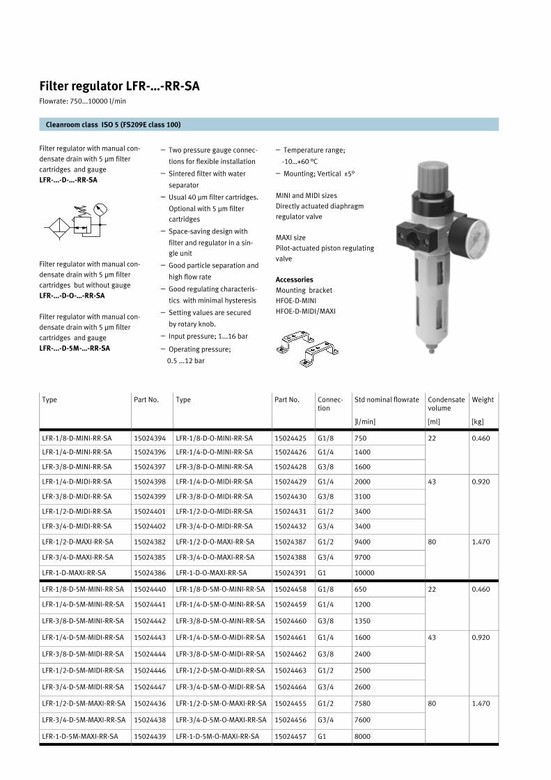
Filter regulator with manual con-
densate drain with 5 µm filter
cartridges and gauge
LFR-...-D-…-RR-SA
Filter regulator with manual con-
densate drain with 5 µm filter
cartridges but without gauge
LFR-...-D-O-…-RR-SA
Filter regulator with manual con-
densate drain with 5 µm filter
cartridges and gauge
LFR-...-D-5M-…-RR-SA
– Two pressure gauge connec-
tions for flexible installation
– Sintered filter with water
separator
– Usual 40 µm filter cartridges.
Optional with 5 µm filter
cartridges
– Space-saving design with
filter and regulator in a sin-
gle unit
– Good particle separation and
high flow rate
– Good regulating characteris-
tics with minimal hysteresis
– Setting values are secured
by rotary knob.
– Input pressure; 1...16 bar
– Operating pressure;
0.5 ...12 bar
– Temperature range;
-10…+60 °C
– Mounting; Vertical ±5°
MINI and MIDI sizes
Directly actuated diaphragm
regulator valve
MAXI size
Pilot-actuated piston regulating
valve
Accessories
Mounting bracket
HFOE-D-MINI
HFOE-D-MIDI/MAXI
Filter regulator LFR-…-RR-SA Flowrate: 750...10000 l/min
Cleanroom class ISO 5 (FS209E class 100)
Type Part No. Type Part No. Connec-tion
Std nominal flowrate Condensate volume
Weight
LFR-1/8-D-MINI-RR-SA 15024394 LFR-1/8-D-O-MINI-RR-SA 15024425 G1/8 750 22 0.460
LFR-1/4-D-MINI-RR-SA 15024396 LFR-1/4-D-O-MINI-RR-SA 15024426 G1/4 1400
LFR-3/8-D-MINI-RR-SA 15024397 LFR-3/8-D-O-MINI-RR-SA 15024428 G3/8 1600
LFR-1/4-D-MIDI-RR-SA 15024398 LFR-1/4-D-O-MIDI-RR-SA 15024429 G1/4 2000 43 0.920
LFR-3/8-D-MIDI-RR-SA 15024399 LFR-3/8-D-O-MIDI-RR-SA 15024430 G3/8 3100
LFR-1/2-D-MIDI-RR-SA 15024401 LFR-1/2-D-O-MIDI-RR-SA 15024431 G1/2 3400
LFR-3/4-D-MIDI-RR-SA 15024402 LFR-3/4-D-O-MIDI-RR-SA 15024432 G3/4 3400
LFR-1/2-D-MAXI-RR-SA 15024382 LFR-1/2-D-O-MAXI-RR-SA 15024387 G1/2 9400 80 1.470
LFR-3/4-D-MAXI-RR-SA 15024385 LFR-3/4-D-O-MAXI-RR-SA 15024388 G3/4 9700
LFR-1-D-MAXI-RR-SA 15024386 LFR-1-D-O-MAXI-RR-SA 15024391 G1 10000
LFR-1/8-D-5M-MINI-RR-SA 15024440 LFR-1/8-D-5M-O-MINI-RR-SA 15024458 G1/8 650 22 0.460
LFR-1/4-D-5M-MINI-RR-SA 15024441 LFR-1/4-D-5M-O-MINI-RR-SA 15024459 G1/4 1200
LFR-3/8-D-5M-MINI-RR-SA 15024442 LFR-3/8-D-5M-O-MINI-RR-SA 15024460 G3/8 1350
LFR-1/4-D-5M-MIDI-RR-SA 15024443 LFR-1/4-D-5M-O-MIDI-RR-SA 15024461 G1/4 1600 43 0.920
LFR-3/8-D-5M-MIDI-RR-SA 15024444 LFR-3/8-D-5M-O-MIDI-RR-SA 15024462 G3/8 2400
LFR-1/2-D-5M-MIDI-RR-SA 15024446 LFR-1/2-D-5M-O-MIDI-RR-SA 15024463 G1/2 2500
LFR-3/4-D-5M-MIDI-RR-SA 15024447 LFR-3/4-D-5M-O-MIDI-RR-SA 15024464 G3/4 2600
LFR-1/2-D-5M-MAXI-RR-SA 15024436 LFR-1/2-D-5M-O-MAXI-RR-SA 15024455 G1/2 7580 80
LFR-3/4-D-5M-MAXI-RR-SA 15024438 LFR-3/4-D-5M-O-MAXI-RR-SA 15024456 G3/4 7600
LFR-1-D-5M-MAXI-RR-SA 15024439 LFR-1-D-5M-O-MAXI-RR-SA 15024457 G1 8000
1.470
]l/min] [ml] [kg]

Filter regulator LFR-…-RR-SA Flowrate: 750...10000 l/min
Cleanroom class ISO 5 (FS209E class 100)
Type B1 B2 B3 B4 B5 B6 B7 D1 D2 D3 D4 D5
LFR-1/8-D-MINI-RR-SA 64 28 40 92 76 36 75 G1/8 31 43 M4 41
LFR-1/4-D-MINI-RR-SA G1/4
LFR-3/8-D-MINI-RR-SA 70 G3/8
LFR-1/4-D-MIDI-RR-SA 85 46 55 111,5 95 44 91 G1/4 50 58 M5 49
LFR-3/8-D-MIDI-RR-SA G3/8
LFR-1/2-D-MIDI-RR-SA G1/2
LFR-3/4-D-MIDI-RR-SA G3/4
LFR-1/2-D-MAXI-RR-SA 96 51 66 124 107 50 100 G1/2 31 43 M5 49
LFR-3/4-D-MAXI-RR-SA G3/4
LFR-1-D-MAXI-RR-SA 116 G1
Type D6 H1 H2 H3 H4 L1 L2 L3 T1 SW1 SW2
LFR-1/8-D-MINI-RR-SA 38 20 38 35 9 193 69 60 7 14
LFR-1/4-D-MINI-RR-SA
LFR-3/8-D-MINI-RR-SA
LFR-1/4-D-MIDI-RR-SA 52 32 45,5 60 13 250 99 80 8 14 24
LFR-3/8-D-MIDI-RR-SA
LFR-1/2-D-MIDI-RR-SA
LFR-3/4-D-MIDI-RR-SA
LFR-1/2-D-MAXI-RR-SA 65 32 51 60 9 252 82 90 8 14 24
LFR-3/4-D-MAXI-RR-SA
LFR-1-D-MAXI-RR-SA 40
24
Barbed fittings for plastic
tubing
Metal bowl guard
Second pressure gauge
Connection
Pressure sensor SDE1- ... -R
Mounting bracket HFOE-D-
… (not included in scope of
delivery)
Installation dimensions
Vacuum suction port
1
2
3
4
5
6
7
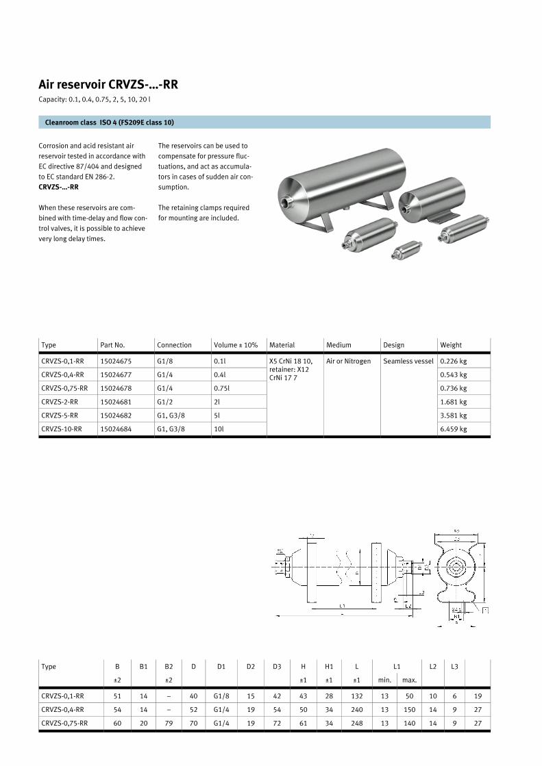
Corrosion and acid resistant air
reservoir tested in accordance with
EC directive 87/404 and designed
to EC standard EN 286-2.
CRVZS-…-RR
When these reservoirs are com-
bined with time-delay and flow con-
trol valves, it is possible to achieve
very long delay times.
The reservoirs can be used to
compensate for pressure fluc-
tuations, and act as accumula-
tors in cases of sudden air con-
sumption.
The retaining clamps required
for mounting are included.
Air reservoir CRVZS-…-RR Capacity: 0.1, 0.4, 0.75, 2, 5, 10, 20 l
Cleanroom class ISO 4 (FS209E class 10)
Type Part No. Connection Volume ± 10% Material Medium Design Weight
CRVZS-0,1-RR 15024675 G1/8 0.1l X5 CrNi 18 10, retainer: X12 CrNi 17 7
Air or Nitrogen Seamless vessel 0.226 kg
CRVZS-0,4-RR 15024677 G1/4 0.4l 0.543 kg
CRVZS-0,75-RR 15024678 G1/4 0.75l 0.736 kg
CRVZS-2-RR 15024681 G1/2 2l 1.681 kg
CRVZS-5-RR 15024682 G1, G3/8 5l 3.581 kg
CRVZS-10-RR 15024684 G1, G3/8 10l 6.459 kg
Type B B1 B2 D D1 D2 D3 H H1 L L2 L3
±2 ±2 ±1 ±1 ±1 min. max.
CRVZS-0,1-RR 51 14 – 40 G1/8 15 42 43 28 132 13 50 10 6 19
CRVZS-0,4-RR 54 14 – 52 G1/4 19 54 50 34 240 13 150 14 9 27
CRVZS-0,75-RR 60 20 79 70 G1/4 19 72 61 34 248 13 140 14 9 27
L1

CRVZS-2-RR
CRVZS-5-RR
CRVZS-10-RR
Air reservoir CRVZS-…-RR
Cleanroom class ISO 4 (FS209E class 10)
Capacity: 0.1, 0.4, 0.75, 2, 5, 10, 20 l
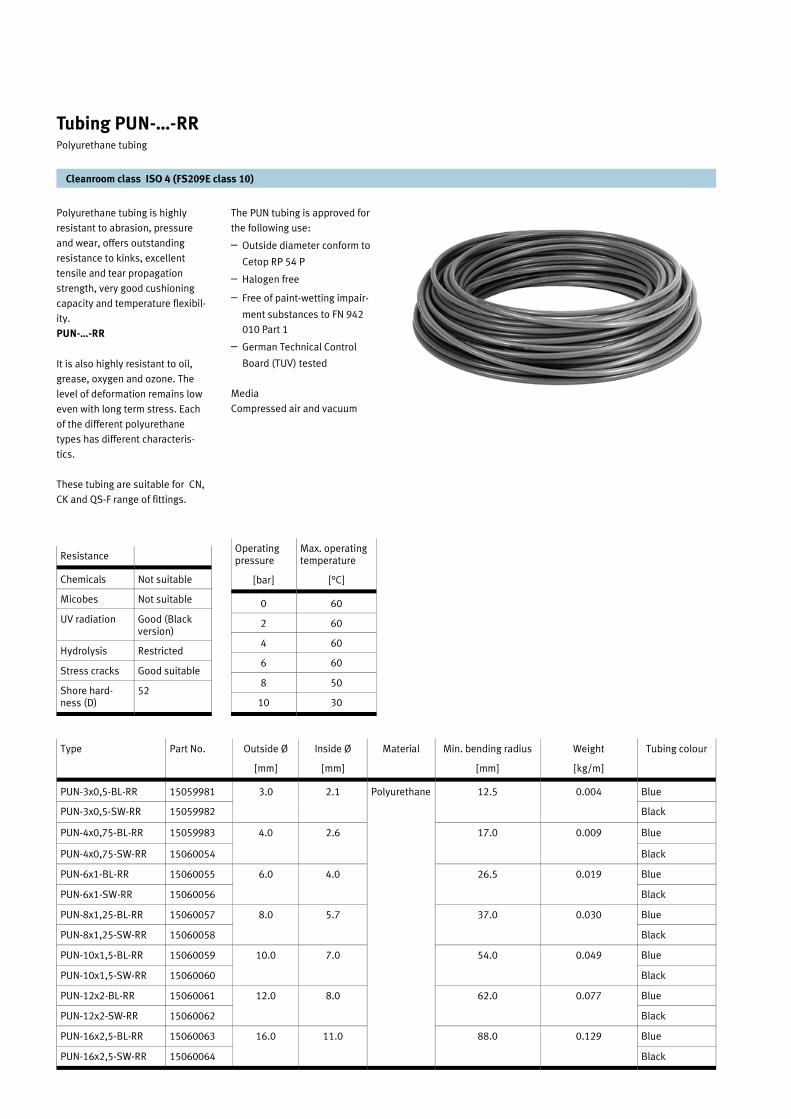
Polyurethane tubing is highly
resistant to abrasion, pressure
and wear, offers outstanding
resistance to kinks, excellent
tensile and tear propagation
strength, very good cushioning
capacity and temperature flexibil-
ity.
PUN-…-RR
It is also highly resistant to oil,
grease, oxygen and ozone. The
level of deformation remains low
even with long term stress. Each
of the different polyurethane
types has different characteris-
tics.
These tubing are suitable for CN,
CK and QS-F range of fittings.
The PUN tubing is approved for
the following use:
– Outside diameter conform to
Cetop RP 54 P
– Halogen free
– Free of paint-wetting impair-
ment substances to FN 942
010 Part 1
– German Technical Control
Board (TUV) tested
Media
Compressed air and vacuum
Cleanroom class ISO 4 (FS209E class 10)
Tubing PUN-…-RR Polyurethane tubing
Type Part No. Outside Ø Inside Ø Material Min. bending radius Weight Tubing colour
[mm] [mm] [mm] [kg/m]
PUN-3x0,5-BL-RR 15059981 3.0 2.1 12.5 0.004 Blue
PUN-3x0,5-SW-RR 15059982 Black
PUN-4x0,75-BL-RR 15059983 4.0 2.6 17.0 0.009 Blue
PUN-4x0,75-SW-RR 15060054 Black
PUN-6x1-BL-RR 15060055 6.0 4.0 26.5 0.019 Blue
PUN-6x1-SW-RR 15060056 Black
PUN-8x1,25-BL-RR 15060057 8.0 5.7 37.0 0.030 Blue
PUN-8x1,25-SW-RR 15060058 Black
PUN-10x1,5-BL-RR 15060059 10.0 7.0 54.0 0.049 Blue
PUN-10x1,5-SW-RR 15060060 Black
PUN-12x2-BL-RR 15060061 12.0 8.0 62.0 0.077 Blue
PUN-12x2-SW-RR 15060062 Black
PUN-16x2,5-BL-RR 15060063 16.0 11.0 88.0 0.129 Blue
PUN-16x2,5-SW-RR 15060064 Black
Polyurethane
Resistance
Chemicals Not suitable
Micobes Not suitable
UV radiation Good (Black version)
Hydrolysis Restricted
Stress cracks Good suitable
Shore hard-ness (D)
52
Operating pressure
Max. operating temperature
[bar] [°C]
0 60
2 60
4 60
6 60
8 50
10 30

Push in fitting range
Threaded connection: M5 to G1/2
Tubing O.D.: 3 to 12 mm
Push in connector with male
straight thread
QS-F-…-RR
– Wide variety of variants, e.g.
rotatable
– Brass fitting, nickel plated
– With sealing ring or
moulded-on sealing rim
– Operating pressure –
0.95...10 bar
– Ambient temperature:
0...150 °C
– Material on collet: Stainless
high alloy steel
– Material: Brass with nickel
and chrome plated
– Approved for used in food
processing
Cleanroom class ISO 4 (FS209E class 10)
Push in fitting series QS-F-…-RR
Type Part No. Connection
For tubing Nominal size]
Material
Ø D1 Type NW Ø D4 L L3 L4 L5 SW1 ß SW2 ß
QS-F-M5-4-RR 15059957 M5 PUN-4-... 2.6 Brass fitting, nickel and chrome plated
8.0 20.5 1.2 4.0 15.0 9 2.5
QS-F-M5-6-RR 15059958 M5 PUN-6-... 2.6 8.0 23.0 1.2 4.0 17.3 11 2.5
QS-F-M7-4-RR 15059851 M7 PUN-4-... 2.6 10.2 22.0 2.5 5.5 15.0 9 2.5
QS-F-M7-6-RR 15059852 M7 PUN-6-... 3.6 11.0 25.3 1.2 5.5 17.3 11 3.5
QS-F-1/8-4-RR 15059828 G1/8 PUN-4-... 2.6 13.5 19.5 3.5 5.5 15.0 9 2.5
QS-F1/8-6-RR 15059832 G1/8 PUN-6-... 4.2 13.5 24.8 5.0 5.5 17.3 11 4
QS-F1/8-8-RR 15059833 G1/8 PUN-8-... 5.2 12.8 26.5 1.5 5.5 18.5 13 5
QS-F-1/4-6-RR 15059834 G1/4 PUN-6-... 4.2 17.0 22.8 4.0 6.5 17.3 11 4
QS-F-1/4-8-RR 15059835 G1/4 PUN-8-... 6.2 17.0 24.0 3.0 6.5 18.5 13 6
QS-F-1/4-10-RR 15059837 G1/4 PUN-10-... 7.3 16.0 28.9 4.0 6.5 20.4 16 7
QS-F-1/4-12-RR 15059853 G1/4 PUN-12-... 7.3 16.0 31.9 4.0 6.5 22.1 19 7
QS-F-3/8-8-RR 15059838 G3/8 PUN-8-... 6.2 20.0 24.0 3.0 7.5 18.5 13 6
QS-F-3/8-10-RR 15059839 G3/8 PUN-10-... 8.3 21.0 29.4 3.0 7.5 20.4 16 8
QS-F-3/8-12-RR 15059841 G3/8 PUN-12-... 10.3 22.0 31.0 3.0 7.5 22.1 19 10
QS-F-1/2-10-RR 15059842 G1/2 PUN-10-... 8.3 24.0 28.9 3.0 9.0 20.4 16 8
QS-F-1/2-12-RR 15059843 G1/2 PUN-12-... 10.3 24.0 31.4 3.0 9.0 22.1 19 10
Dimensions
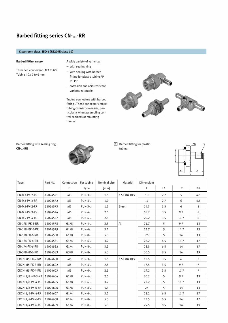
Barbed fitting range
Threaded connection: M3 to G3
Tubing I.D.: 2 to 6 mm
Barbed fitting with sealing ring
CN-…-RR
A wide variety of variants:
– with sealing ring
– with sealing with barbed
fitting for plastic tubing PP
PU PP
– corrosion and acid-resistant
variants rotatable
Tubing connectors with barbed
fitting . These connectors make
tubing connection easier, par-
ticularly when assembling con-
trol cabinets or mounting
frames.
Cleanroom class ISO 4 (FS209E class 10)
Barbed fitting series CN-…-RR
Type Part No. Connection For tubing Nominal size Material Dimensions
D Type [mm] L L1 L2 ß
CN-M3-PK-2-RR 15024571 M3 PUN-3-... 1.5 X 5 CrNi 18 9 10 2.7 5 4.5
CN-M3-PK-3-RR 15024572 M3 PUN-4-... 1.9 11 2.7 6 4.5
CN-M5-PK-2-RR 15024573 M5 PUN-3-... 1.5 Steel 14.5 3.5 6 8
CN-M5-PK-3-RR 15024574 M5 PUN-4-... 2.5 18.2 3.5 9.7 8
CN-M5-PK-4-RR 15024577 M5 PUN-6-... 2.5 20.2 3.5 11.7 8
CN-1/8 -PK-3-RR 15024578 G1/8 PUN-4-... 2.5 Al 21.7 5 9.7 13
CN-1/8 -PK-4-RR 15024579 G1/8 PUN-6-... 3.2 23.7 5 11.7 13
CN-1/8-PK-6-RR 15024580 G1/8 PUN-8-... 5.3 26 5 14 13
CN-1/4-PK-4-RR 15024581 G1/4 PUN-6-... 3.2 26.2 6.5 11.7 17
CN-1/4-PK-6-RR 15024582 G1/4 PUN-8-... 5.3 28.5 6.5 14 17
CN-3/8-PK-6-RR 15024583 G3/8 PUN-8-... 5.3 30.5 8.5 14 19
CRCN-M5-PK-2-RR 15024600 M5 PUN-3-... 1.5 X 5 CrNi 18 9 13.5 3.5 6 7
CRCN-M5-PK-3-RR 15024602 M5 PUN-4-... 2.5 17.5 3.5 9.7 7
CRCN-M5-PK-4-RR 15024603 M5 PUN-6-... 2.5 19.2 3.5 11.7 7
CRCN-1/8 -PK-3-RR 15024604 G1/8 PUN-4-... 2.5 20.2 5 9.7 13
CRCN-1/8-PK-4-RR 15024605 G1/8 PUN-6-... 3.2 22.2 5 11.7 13
CRCN-1/8-PK-6-RR 15024606 G1/8 PUN-8-... 5.3 24 5 14 13
CRCN-1/4-PK-4-RR 15024607 G1/4 PUN-6-... 3.2 25.2 6.5 11.7 17
CRCN-1/4-PK-6-RR 15024608 G1/4 PUN-8-... 5.3 27.5 6.5 14 17
CRCN-1/4-PK-6-RR 15024609 G1/4 PUN-8-... 5.3 29.5 8.5 14 19
Barbed fitting for plastic
tubing
1

L-barbed fitting. Rotatble 360°
LCN-…-RR
L-barbed fitting. Rotatble 360°
LCNH-…-RR
Cleanroom class ISO 4 (FS209E class 10)
Barbed fitting series CN-…-RR
Type Part No. Connec-tion
For tubing Nominal size
Material Weight Dimensions
D Type [mm] [kg] H H1 L L1 L2 ß
LCN-M3-PK-2-B-RR 15024619 M3 PUN-3-... 1.3 X5 CrNi 189, die-cast zinc
0.002 12.8 8.1 9.6 2.7 6 4.5
LCN-M3-PK-3-RR 15024620 M3 PUN-4-... 2 0.002 14 8.7 13.3 2.7 9.7 4.5
LCN-M5-PK-2-RR 15024623 M5 PUN-3-... 1.3 Steel, die-cast zinc
0.004 15.3 9.1 9.6 3.5 6 8
LCN-M5-PK-3-RR 15024624 M5 PUN-4-... 2 0.005 19.4 13.3 14.7 3.5 9.7 8
LCN-M5-PK-4-RR 15024625 M5 PUN-6-... 2.9 0.006 20.9 13.9 16.7 3.5 11.7 8
LCN-1/8-PK-3-RR 15024626 G1/8 PUN-4-... 2 Al, die-cast zinc
0.009 21.2 13.6 17.5 5 9.7 13
LCN-1/8-PK-4-RR 15024627 G1/8 PUN-6-... 2.9 0.01 22.6 14.1 19.5 5 11.7 13
LCN-1/8-PK-6-RR 15024628 G1/8 PUN-8-... 4.9 0.011 24.6 15.1 22 5 14.2 13
LCN-1/4-PK-4-RR 15024629 G1/4 PUN-6-... 2.9 0.013 25.6 15.6 19.5 6.5 11.7 17
LCN-1/4-PK-6-RR 15024630 G1/4 PUN-8-... 4.9 0.015 27.5 16.6 22 6.5 14.2 17
LCN-3/8-PK-6-RR 15024631 G3/8 PUN-8-... 4.9 0.02 29.5 16.6 22 8.5 14.2 19
LCNH-M5-PK-2-RR 15024636 M5 PUN-3-... 1.3 Steel, die-cast zinc
0.008 26.2 20.7 9.6 3.5 6 8
LCNH-M5-PK-3-RR 15024637 M5 PUN-4-... 2 0.009 28 21.9 14.7 3.5 9.7 8
LCNH-M5-PK-4-RR 15024638 M5 PUN-6-... 2.9 0.01 29.5 22.5 16.7 3.5 11.7 8
LCNH-1/8-PK-3-RR 15024641 G1/8 PUN-4-... 2 Al, die-cast zinc
0.013 31.8 24.2 17.5 5 9.7 13
LCNH-1/8-PK-4-RR 15024642 G1/8 PUN-6-... 2.9 0.014 33.2 24.7 19.5 5 11.7 13
LCNH-1/8-PK-6-RR 15024643 G1/8 PUN-4-... 4.9 0.016 35.1 25.7 22 5 14.2 13
LCNH-1/4-PK-4-RR 15024644 G1/4 PUN-6-... 2.9 0.021 36.2 26.2 19.5 6.5 11.7 17
LCNH-1/4-PK-6-RR 15024645 G1/4 PUN-8-... 4.9 0.022 38.1 27.2 22 6.5 14.2 17
LCNH-3/8-PK-6-RR 15024646 G3/8 PUN-8-... 4.9 0.029 40.1 27.2 22 8.5 14.2 19
Barbed fitting for plastic
tubing
1
Barbed fitting for plastic
tubing
1
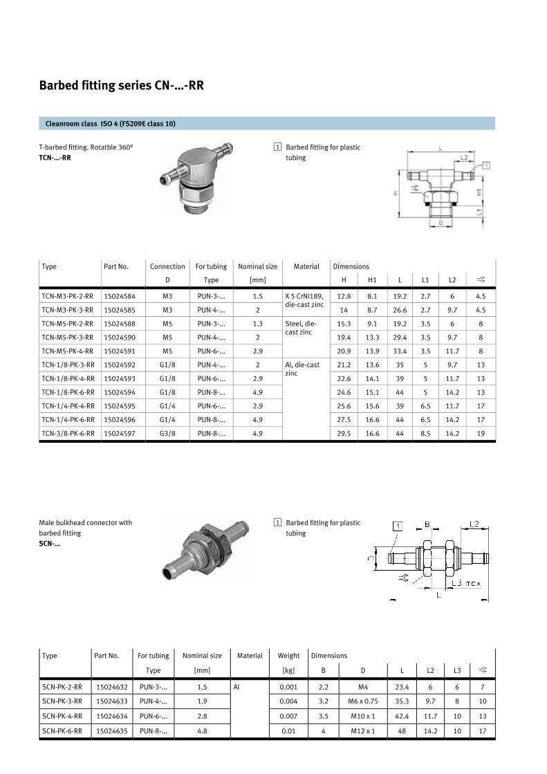
T-barbed fitting. Rotatble 360°
TCN-…-RR
Male bulkhead connector with
barbed fitting
SCN-...
Cleanroom class ISO 4 (FS209E class 10)
Barbed fitting series CN-…-RR
Type Part No. Connection For tubing Nominal size Material Dimensions
D Type [mm] H H1 L L1 L2 ß
TCN-M3-PK-2-RR 15024584 M3 PUN-3-... 1.5 X 5 CrNi189, die-cast zinc
12.8 8.1 19.2 2.7 6 4.5
TCN-M3-PK-3-RR 15024585 M3 PUN-4-... 2 14 8.7 26.6 2.7 9.7 4.5
TCN-M5-PK-2-RR 15024588 M5 PUN-3-... 1.3 Steel, die-cast zinc
15.3 9.1 19.2 3.5 6 8
TCN-M5-PK-3-RR 15024590 M5 PUN-4-... 2 19.4 13.3 29.4 3.5 9.7 8
TCN-M5-PK-4-RR 15024591 M5 PUN-6-... 2.9 20.9 13.9 33.4 3.5 11.7 8
TCN-1/8-PK-3-RR 15024592 G1/8 PUN-4-... 2 Al, die-cast zinc
21.2 13.6 35 5 9.7 13
TCN-1/8-PK-4-RR 15024593 G1/8 PUN-6-... 2.9 22.6 14.1 39 5 11.7 13
TCN-1/8-PK-6-RR 15024594 G1/8 PUN-8-... 4.9 24.6 15.1 44 5 14.2 13
TCN-1/4-PK-4-RR 15024595 G1/4 PUN-6-... 2.9 25.6 15.6 39 6.5 11.7 17
TCN-1/4-PK-6-RR 15024596 G1/4 PUN-8-... 4.9 27.5 16.6 44 6.5 14.2 17
TCN-3/8-PK-6-RR 15024597 G3/8 PUN-8-... 4.9 29.5 16.6 44 8.5 14.2 19
Type Part No. For tubing Nominal size Material Weight Dimensions
Type [mm] [kg] B D L L2 L3 ß
SCN-PK-2-RR 15024632 PUN-3-... 1.5 Al 0.001 2.2 M4 23.4 6 6 7
SCN-PK-3-RR 15024633 PUN-4-... 1.9 0.004 3.2 M6 x 0.75 35.3 9.7 8 10
SCN-PK-4-RR 15024634 PUN-6-... 2.8 0.007 3.5 M10 x 1 42.4 11.7 10 13
SCN-PK-6-RR 15024635 PUN-8-... 4.8 0.01 4 M12 x 1 48 14.2 10 17
Barbed fitting for plastic
tubing
1
Barbed fitting for plastic
tubing
1

Barbed T connector
FCN-…-RR
Cleanroom class ISO 4 (FS209E class 10)
Barbed fitting series CN-…-RR
Type Part No. For tubing Type Nomi-nal size
Material Weight Dimensions
D1 D2 [mm] [kg] B B1 D3 H H1 H2 L L1 L2
FCN-3-PK-2-B-RR 15024611 PUN-3-... PUN-3-... 1.3 Die-cast zinc
0.005 4 6 3.2 15.7 3.1 2.6 28 8 6
FCN-3-PK-3-RR 15024612 PUN-4-... PUN-4-... 2 0.008 5.2 8.4 4.3 17.9 3.5 3.9 38.4 10 9.7
FCN-3-PK-3/2-RR 15024613 PUN-4-... PUN-3-... 2/1.3 0.008 5.2 8.4 4.3 21.6 3.5 3.9 38.4 10 9.7
FCN-3-PK-4-RR 15024614 PUN-6-... PUN-6-... 2.9 0.012 7 10.2 4.3 22 3.5 4.3 44.4 12 11.7
FCN-3-PK-4/3-RR 15024615 PUN-6-... PUN-4-... 2.9/2 0.012 7 10.2 4.3 24 3.5 4.3 44.4 12 11.7
FCN-3-PK-6-RR 15024616 PUN-8-... PUN-8-... 4.9 0.016 8.8 12 4.3 25.9 4.4 5.3 49.4 12 14.2
FCN-3-PK-6/4-RR 15024617 PUN-8-... PUN-6-... 4.9/2.9 0.016 8.8 12 4.3 28.4 4.4 5.3 49.4 12 14.2
Barbed fitting for plastic
tubing
1

Quick connector range
Threaded connection: M5 to G1/2
Tubing I.D.: 3 to 13 mm
– Wide variety of variants, e.g.
rotatable
– Aluminum or polymer design
– With sealing ring or moulded-
on sealing rim
Quick connector with male thread
CK-…-RR
Cleanroom class ISO 4 (FS209E class 10)
Quick connector series CK-…-RR
Type Part No. Connection For tubing Nominal size Material Dimensions
D Type (mm) B L ß ß1
CK-M5-PK-3-RR 15024505 M5 PUN-4-... 2.4 Steel/Al with sealing ring
3.7 17.4 7 8
CK-M5-PK-4-RR 15024506 M5 PUN-6-... 2.4 3.7 18.7 10 –
CK-1/8-PK-3-RR 15024507 G1/8 PUN-4-... 2.4 Al, blue ano-dised with sealing ring
5 20.4 13 8
CK-1/8-PK-4-RR 15024508 G1/8 PUN-6-... 3.4 5 23.5 13 12
CK-1/8-PK6-RR 15024509 G1/8 PUN-8-... 5.4 5 23.6 13 14
CK-1/4-PK-4-RR 15024510 G1/4 PUN-6-... 3.4 6.5 26.5 17 12
CK-1/4-PK-6-RR 15024511 G1/4 PUN-8-... 5.4 6.5 26.6 17 14
CK-1/4-PK-9-RR 15024512 G1/4 PUN-12-... 8 6.5 29.9 17 19
CK-3/8-PK-6-RR 15024513 G3/8 PUN-8-... 5.3 8.5 28.6 19 14
CK-3/8-PK-9-RR 15024514 G3/8 PUN-12-... 8 8.5 31.9 19 19
CK-3/8-PK-13-RR 15024515 G3/8 PUN-16-... 12 8.5 34.7 24 24
CK-1/2-PK-13-RR 15024516 G1/2 PUN-16-... 12 11.5 37.7 24 24

Quick connector with female
thread and sealing ring
ACK-…-RR
L-quick connector. Rotatable
LCK-…-RR
Cleanroom class ISO 4 (FS209E class 10)
Quick connector series CK-…-RR
Type Part No. Connection For tubing Nominal size Material Dimensions
D Type (mm)] B L ß ß1
ACK-1/8-PK-3-RR 15024528 G1/8 PUN-4-... 2.4 Al, blue ano-dised
9 23.9 13 8
ACK-1/8-PK-4-RR 15024529 G1/8 PUN-6-... 3.4 9 27 13 12
ACK-1/8-PK-6-RR 15024531 G1/8 PUN-8-... 5.3 9 27 13 14
ACK-1/4-PK-4-RR 15024532 G1/4 PUN-6-... 3.4 12 30 17 12
ACK-1/4-PK-6-RR 15024533 G1/4 PUN-8-... 5.3 12 30 17 14
ACK-3/8-PK-6-RR 15024534 G3/8 PUN-8-... 5.3 12 31 19 14
ACK-3/8-PK-9-RR 15024535 G3/8 PUN-12-... 8 15 37.4 19 19
ACK-1/2-PK-13-RR 15024539 G1/2 PUN-16-... 12 15 40.2 27 24
Type Part No. Connec-tion
For tubing Nominal size
Material Dimensions
D Type [mm] B C H H1 L L1 ß
LCK-M5-PK-3-RR 15024545 M5 PUN-4-... 2 Die-cast zinc with 2 seal-ing rings
4.2 10 21.1 16.1 18.2 5.7 7
LCK-M5-PK-4-RR 15024546 M5 PUN-6-... 2.9 3.4 11 21.1 16.1 18.2 5.7 7
LCK-1/8-PK-3-RR 15024547 G1/8 PUN-4-... 2 6.4 16 27.1 19.1 22 6 13
LCK-1/8-PK-4-RR 15024548 G1/8 PUN-6-... 2.9 6 16 30.2 22.2 27.5 9 13
LCK-1/8-PK-6-RR 15024549 G1/8 PUN-8-... 4.9 6 16 30.3 22.3 27.5 9 13
LCK-1/4-PK-4-RR 15024550 G1/4 PUN-6-... 2.9 7 20 34.2 24.2 28.5 9 17
LCK-1/4-PK-4-RR 15024551 G1/4 PUN-6-... 4.9 6.8 20 34.3 24.3 28.5 9.1 17
LCK-1/4-PK-9-RR 15024552 G1/4 PUN-12-... 8 7.3 20 37.6 27.6 33.7 11.6 17
LCK-3/8-PK-6-RR 15024553 G3/8 PUN-8-... 4.9 8.6 25 39.3 26.8 31 9.1 22
LCK-3/8-PK-9-RR 15024554 G3/8 PUN-12-... 8 9.1 25 42.6 30.1 36.5 11.6 22
LCK-1/2-PK-13-RR 15024555 G1/2 PUN-16-... 11.7 12.7 30 49.2 34.2 50 16.5 27
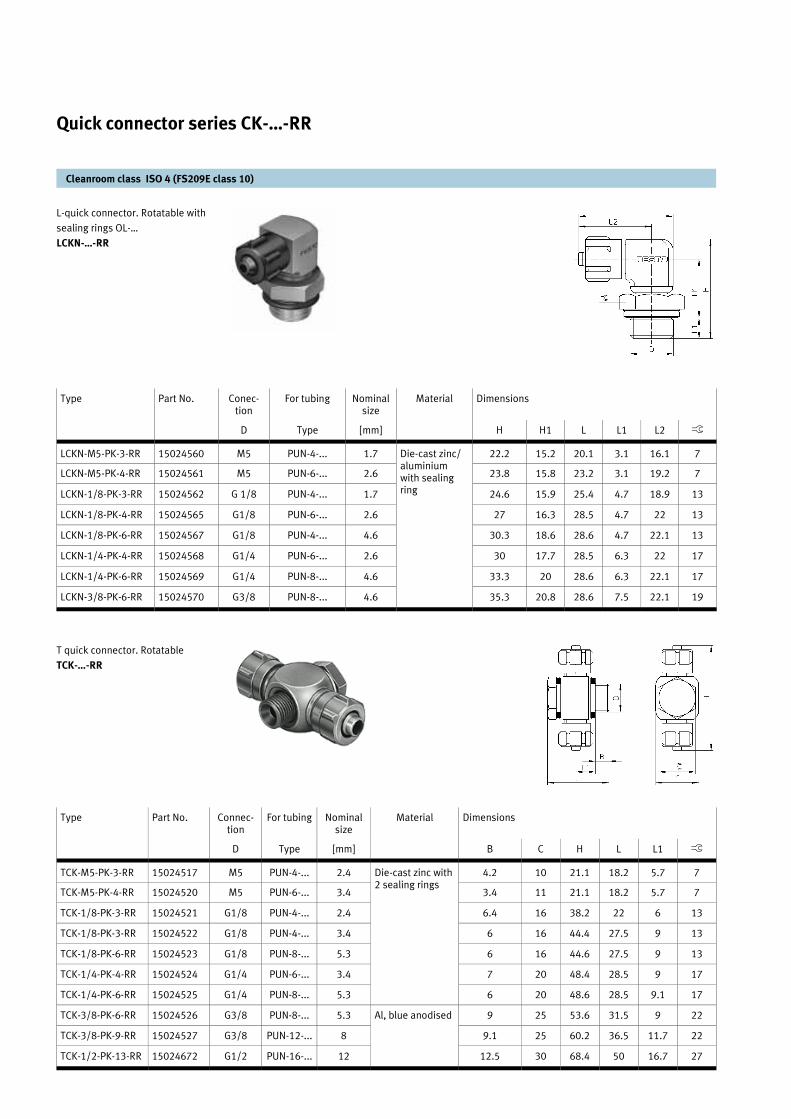
L-quick connector. Rotatable with
sealing rings OL-…
LCKN-…-RR
T quick connector. Rotatable
TCK-…-RR
Type Part No. Conec-tion
For tubing Nominal size
Material Dimensions
D Type [mm] H H1 L L1 L2 ß
LCKN-M5-PK-3-RR 15024560 M5 PUN-4-... 1.7 Die-cast zinc/aluminium with sealing ring
22.2 15.2 20.1 3.1 16.1 7
LCKN-M5-PK-4-RR 15024561 M5 PUN-6-... 2.6 23.8 15.8 23.2 3.1 19.2 7
LCKN-1/8-PK-3-RR 15024562 G 1/8 PUN-4-... 1.7 24.6 15.9 25.4 4.7 18.9 13
LCKN-1/8-PK-4-RR 15024565 G1/8 PUN-6-... 2.6 27 16.3 28.5 4.7 22 13
LCKN-1/8-PK-6-RR 15024567 G1/8 PUN-4-... 4.6 30.3 18.6 28.6 4.7 22.1 13
LCKN-1/4-PK-4-RR 15024568 G1/4 PUN-6-... 2.6 30 17.7 28.5 6.3 22 17
LCKN-1/4-PK-6-RR 15024569 G1/4 PUN-8-... 4.6 33.3 20 28.6 6.3 22.1 17
LCKN-3/8-PK-6-RR 15024570 G3/8 PUN-8-... 4.6 35.3 20.8 28.6 7.5 22.1 19
Cleanroom class ISO 4 (FS209E class 10)
Quick connector series CK-…-RR
Type Part No. Connec-tion
For tubing Nominal size
Material Dimensions
D Type [mm] B C H L L1 ß
TCK-M5-PK-3-RR 15024517 M5 PUN-4-... 2.4 Die-cast zinc with 2 sealing rings
4.2 10 21.1 18.2 5.7 7
TCK-M5-PK-4-RR 15024520 M5 PUN-6-... 3.4 3.4 11 21.1 18.2 5.7 7
TCK-1/8-PK-3-RR 15024521 G1/8 PUN-4-... 2.4 6.4 16 38.2 22 6 13
TCK-1/8-PK-3-RR 15024522 G1/8 PUN-4-... 3.4 6 16 44.4 27.5 9 13
TCK-1/8-PK-6-RR 15024523 G1/8 PUN-8-... 5.3 6 16 44.6 27.5 9 13
TCK-1/4-PK-4-RR 15024524 G1/4 PUN-6-... 3.4 7 20 48.4 28.5 9 17
TCK-1/4-PK-6-RR 15024525 G1/4 PUN-8-... 5.3 6 20 48.6 28.5 9.1 17
TCK-3/8-PK-6-RR 15024526 G3/8 PUN-8-... 5.3 Al, blue anodised 9 25 53.6 31.5 9 22
TCK-3/8-PK-9-RR 15024527 G3/8 PUN-12-... 8 9.1 25 60.2 36.5 11.7 22
TCK-1/2-PK-13-RR 15024672 G1/2 PUN-16-... 12 12.5 30 68.4 50 16.7 27
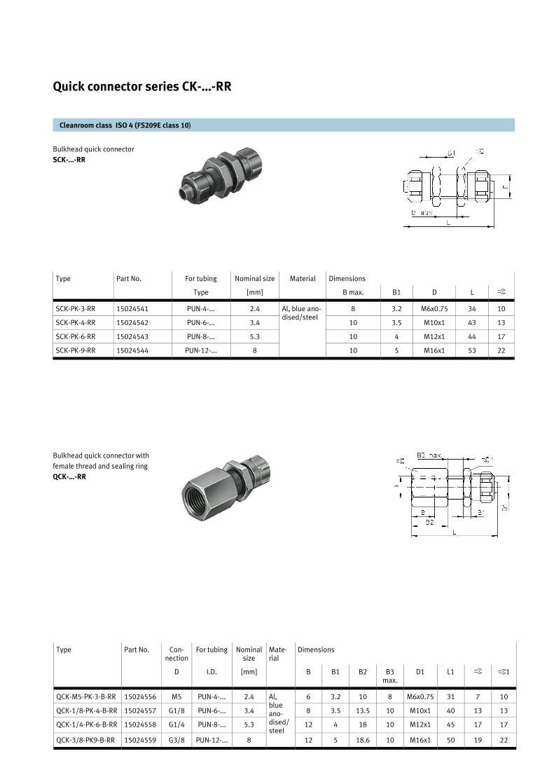
Bulkhead quick connector
SCK-…-RR
Bulkhead quick connector with
female thread and sealing ring
QCK-…-RR
Cleanroom class ISO 4 (FS209E class 10)
Quick connector series CK-…-RR
Type Part No. For tubing Nominal size Material Dimensions
Type [mm] B max. B1 D L ß
SCK-PK-3-RR 15024541 PUN-4-... 2.4 Al, blue ano-dised/steel
8 3.2 M6x0.75 34 10
SCK-PK-4-RR 15024542 PUN-6-... 3.4 10 3.5 M10x1 43 13
SCK-PK-6-RR 15024543 PUN-8-... 5.3 10 4 M12x1 44 17
SCK-PK-9-RR 15024544 PUN-12-... 8 10 5 M16x1 53 22
Type Part No. Con-nection
For tubing Nominal size
Mate-rial
Dimensions
D I.D. [mm] B B1 B2 B3 max.
D1 L1 ß ß1
QCK-M5-PK-3-B-RR 15024556 M5 PUN-4-... 2.4 Al,blue ano-dised/steel
6 3.2 10 8 M6x0.75 31 7 10
QCK-1/8-PK-4-B-RR 15024557 G1/8 PUN-6-... 3.4 8 3.5 13.5 10 M10x1 40 13 13
QCK-1/4-PK-6-B-RR 15024558 G1/4 PUN-8-... 5.3 12 4 18 10 M12x1 45 17 17
QCK-3/8-PK9-B-RR 15024559 G3/8 PUN-12-... 8 12 5 18.6 10 M16x1 50 19 22

This captive sealing ring is effective
even when only gently tightened, is
reusable and can be used at hy-
draulic pressures of up to 30 bar.
OL-…-RR
Operating pressure –1 ... +30 bar
Temperature range –30 ... +100 °C
Cleanroom class ISO 4 (FS209E class 10)
Sealing rings OL-…-RR Ø M5, M10, M12, M14, M16, M22, G1/8, G1/4, G3/8, G1/2, G3/4
Type Part No. For thread Material Max. permissible tightening torque Weight [kg]
OL-M5-RR 15024659 M5 Stainless steel & NBR
2 Nm 0.001
OL-1/8-RR 15024660 G1/8 4 Nm
OL-1/4-RR 15024661 G1/4 11 Nm
OL-3/8-RR 15024662 G3/8 AI & NBR 40 Nm 0.002
OL-1/2-RR 15024663 G1/2 50 Nm
OL-3/4-RR 15024664 G3/4 100 Nm
OL-M6-RR 15024665 M6 St. steel & NBR - 0.001
OL-M10-RR 15024666 M10 Brass & NBR 12 Nm 0.006
OL-M12-RR 15024667 M12 20 Nm 0.007
OL-M14-RR 15024668 M14 35 Nm 0.008
OL-M16-RR 15024669 M16 - 0.096
OL-M22-RR 15024670 M22 - 0.025
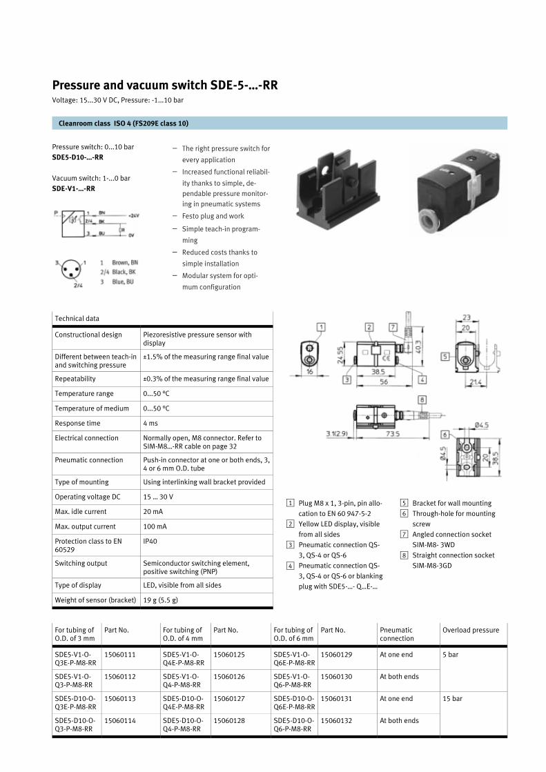
Pressure and vacuum switch SDE-5-…-RR
Cleanroom class ISO 4 (FS209E class 10)
Pressure switch: 0...10 bar
SDE5-D10-…-RR
Vacuum switch: 1-...0 bar
SDE-V1-…-RR
– The right pressure switch for
every application
– Increased functional reliabil-
ity thanks to simple, de-
pendable pressure monitor-
ing in pneumatic systems
– Festo plug and work
– Simple teach-in program-
ming
– Reduced costs thanks to
simple installation
– Modular system for opti-
mum configuration
For tubing of O.D. of 3 mm
Part No. For tubing of O.D. of 4 mm
Part No. For tubing of O.D. of 6 mm
Part No. Pneumatic connection
Overload pressure
SDE5-V1-O-Q3E-P-M8-RR
15060111 SDE5-V1-O-Q4E-P-M8-RR
15060125 SDE5-V1-O-Q6E-P-M8-RR
15060129 At one end 5 bar
SDE5-V1-O-Q3-P-M8-RR
15060112 SDE5-V1-O-Q4-P-M8-RR
15060126 SDE5-V1-O-Q6-P-M8-RR
15060130 At both ends
SDE5-D10-O-Q3E-P-M8-RR
15060113 SDE5-D10-O-Q4E-P-M8-RR
15060127 SDE5-D10-O-Q6E-P-M8-RR
15060131 At one end 15 bar
SDE5-D10-O-Q3-P-M8-RR
15060114 SDE5-D10-O-Q4-P-M8-RR
15060128 SDE5-D10-O-Q6-P-M8-RR
15060132 At both ends
Technical data
Constructional design Piezoresistive pressure sensor with display
Different between teach-in and switching pressure
±1.5% of the measuring range final value
Repeatability ±0.3% of the measuring range final value
Temperature range 0...50 °C
Temperature of medium 0...50 °C
Response time 4 ms
Electrical connection Normally open, M8 connector. Refer to SIM-M8…-RR cable on page 32
Pneumatic connection Push-in connector at one or both ends, 3, 4 or 6 mm O.D. tube
Type of mounting Using interlinking wall bracket provided
Operating voltage DC 15 … 30 V
Max. idle current 20 mA
Max. output current 100 mA
Protection class to EN 60529
IP40
Switching output Semiconductor switching element, positive switching (PNP)
Type of display LED, visible from all sides
Weight of sensor (bracket) 19 g (5.5 g)
Plug M8 x 1, 3-pin, pin allo-
cation to EN 60 947-5-2
Yellow LED display, visible
from all sides
Pneumatic connection QS-
3, QS-4 or QS-6
Pneumatic connection QS-
3, QS-4 or QS-6 or blanking
plug with SDE5-…- Q…E-…
1
2
3
4
Bracket for wall mounting
Through-hole for mounting
screw
Angled connection socket
SIM-M8- 3WD
Straight connection socket
SIM-M8-3GD
5
6
7
8
Voltage: 15...30 V DC, Pressure: -1...10 bar
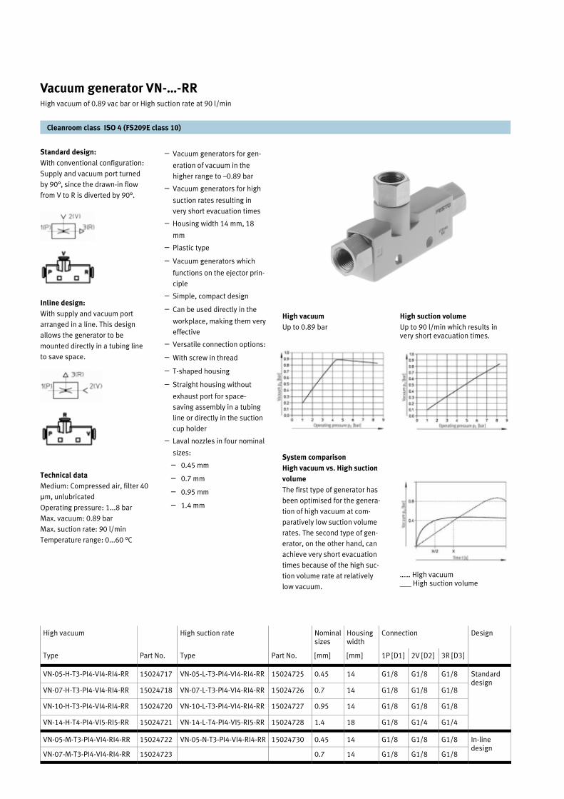
Standard design:
With conventional configuration:
Supply and vacuum port turned
by 90°, since the drawn-in flow
from V to R is diverted by 90°.
Inline design:
With supply and vacuum port
arranged in a line. This design
allows the generator to be
mounted directly in a tubing line
to save space.
Technical data
Medium: Compressed air, filter 40
µm, unlubricated
Operating pressure: 1...8 bar
Max. vacuum: 0.89 bar
Max. suction rate: 90 l/min
Temperature range: 0...60 °C
High suction volume
Up to 90 l/min which results in very short evacuation times.
…… High vacuum ___ High suction volume
Cleanroom class ISO 4 (FS209E class 10)
Vacuum generator VN-…-RR High vacuum of 0.89 vac bar or High suction rate at 90 l/min
– Vacuum generators for gen-
eration of vacuum in the
higher range to –0.89 bar
– Vacuum generators for high
suction rates resulting in
very short evacuation times
– Housing width 14 mm, 18
mm
– Plastic type
– Vacuum generators which
functions on the ejector prin-
ciple
– Simple, compact design
– Can be used directly in the
workplace, making them very
effective
– Versatile connection options:
– With screw in thread
– T-shaped housing
– Straight housing without
exhaust port for space-
saving assembly in a tubing
line or directly in the suction
cup holder
– Laval nozzles in four nominal
sizes:
– 0.45 mm
– 0.7 mm
– 0.95 mm
– 1.4 mm
High vacuum
Up to 0.89 bar
System comparison
High vacuum vs. High suction
volume
The first type of generator has
been optimised for the genera-
tion of high vacuum at com-
paratively low suction volume
rates. The second type of gen-
erator, on the other hand, can
achieve very short evacuation
times because of the high suc-
tion volume rate at relatively
low vacuum.
High vacuum High suction rate Nominal sizes
Housing width
Design
Type Part No. Type Part No. [mm] [mm] 1P [D1] 2V [D2] 3R [D3]
VN-05-H-T3-PI4-VI4-RI4-RR 15024717 VN-05-L-T3-PI4-VI4-RI4-RR 15024725 0.45 14 G1/8 G1/8 G1/8 Standard design
VN-07-H-T3-PI4-VI4-RI4-RR 15024718 VN-07-L-T3-PI4-VI4-RI4-RR 15024726 0.7 14 G1/8 G1/8 G1/8
VN-10-H-T3-PI4-VI4-RI4-RR 15024720 VN-10-L-T3-PI4-VI4-RI4-RR 15024727 0.95 14 G1/8 G1/8 G1/8
VN-14-H-T4-PI4-VI5-RI5-RR 15024721 VN-14-L-T4-PI4-VI5-RI5-RR 15024728 1.4 18 G1/8 G1/4 G1/4
VN-05-M-T3-PI4-VI4-RI4-RR 15024722 VN-05-N-T3-PI4-VI4-RI4-RR 15024730 0.45 14 G1/8 G1/8 G1/8 In-line design
VN-07-M-T3-PI4-VI4-RI4-RR 15024723 0.7 14 G1/8 G1/8 G1/8
Connection
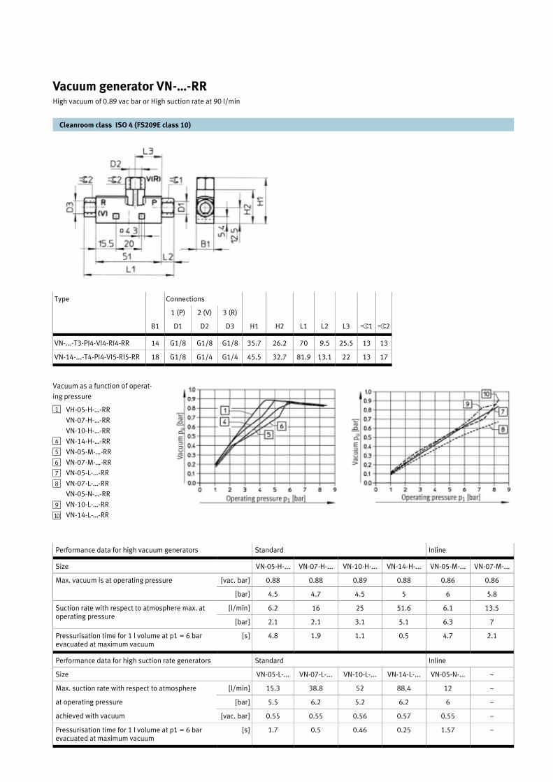
Vacuum as a function of operat-
ing pressure
Cleanroom class ISO 4 (FS209E class 10)
Vacuum generator VN-…-RR
Performance data for high vacuum generators Standard Inline
Size VN-05-H-... VN-07-H-... VN-10-H-... VN-14-H-... VN-05-M-... VN-07-M-...
Max. vacuum is at operating pressure [vac. bar] 0.88 0.88 0.89 0.88 0.86 0.86
[bar] 4.5 4.7 4.5 5 6 5.8
[l/min] 6.2 16 25 51.6 6.1 13.5
[bar] 2.1 2.1 3.1 5.1 6.3 7
Pressurisation time for 1 l volume at p1 = 6 bar evacuated at maximum vacuum
[s] 4.8 1.9 1.1 0.5 4.7 2.1
Performance data for high suction rate generators Standard Inline
Max. suction rate with respect to atmosphere [l/min] 15.3 38.8 52 88.4 12 –
at operating pressure [bar] 5.5 6.2 5.2 6.2 6 –
achieved with vacuum [vac. bar] 0.55 0.55 0.56 0.57 0.55 –
Pressurisation time for 1 l volume at p1 = 6 bar evacuated at maximum vacuum
[s] 1.7 0.5 0.46 0.25 1.57 –
Suction rate with respect to atmosphere max. at operating pressure
Size VN-05-L-... VN-07-L-... VN-10-L-... VN-14-L-... VN-05-N-... –
High vacuum of 0.89 vac bar or High suction rate at 90 l/min
Type
1 (P) 2 (V) 3 (R)
B1 D1 D2 D3 H1 H2 L1 L2 L3 ß1 ß2
VN-...-T3-PI4-VI4-RI4-RR 14 G1/8 G1/8 G1/8 35.7 26.2 70 9.5 25.5 13 13
VN-14-...-T4-PI4-VI5-RI5-RR 18 G1/8 G1/4 G1/4 45.5 32.7 81.9 13.1 22 13 17
Connections
VH-05-H-…-RR
VN-07-H-…-RR
VN-10-H-…-RR
VN-14-H-…-RR
VN-05-M-…-RR
VN-07-M-…-RR
VN-05-L-…-RR
VN-07-L-…-RR
VN-05-N-…-RR
VN-10-L-…-RR
VN-14-L-…-RR
1
4
56
7
8
9
aJ

Cleanroom class ISO 4 (FS209E class 10)
Vacuum generator VN-…-RR High vacuum of 0.89 vac bar or High suction rate at 90 l/min
Suction flow rate
(with respect to atmosphere)
as a function of operating pres-
sure
High vacuum
Suction flow rate
(with respect to atmosphere)
as a function of operating pres-
sure
High suction rate
VH-05-H…-RR 1 VH-05-M-…-RR 5 VH-07-H…-RR 2 VH-07-M-…-RR 6
VH-10-H-…-RR 3 VH-14-H-…-RR 4
VH-05-L-…-RR 7 VH-05-N-…-RR aA VH-07-L-…-RR 8
VH-10-L-…-RR 9 VH-14-L-...-RR aJ

Information

Information General information
Introduction to Cleanroom
The term “Cleanroom” is some-
thing you associate with in
modern industries. However, the
root of cleanroom design goes
back more than a century. Think
of the need to control contamina-
tion in hospitals and you would
be able to imagine the first
cleanroom.
It can be seen that the require-
ment for cleanroom can be
broadly divided into two areas:
– That in which inanimate parti-
cles are a problem and where
their presence may prevent a
product functioning or reduce
its useful life.
– To ensure the absence of mi-
crobe carrying particles whose
growth could lead to human
infection.
Definition of cleanroom
It is clear that a cleanroom is a
room that is clean. However, a
cleanroom now has a special
meaning and it is defined in
ISO 144641 as:
“A room in which the concentra-
tion of airborne particles is con-
trolled and which contains one or
more clean zones.”
And in ISO 14644-1 as:
“A room in which the concentra-
tion of airborne particles is con-
trolled, and which is constructed
and used in a manner to minimise
the introduction, generation and
retention of particles inside the
room and in which other relevant
particles inside the room and in
which other relevant parameters
e.g. temperature, humidity and
pressure, are controlled as neces-
sary.”
Classification of cleanroom
Cleanroom are classified by the
cleanliness of their air. The
method most easily understood
and universally applied is the
one suggested in versions of
Federal Standard 209 up to
edition "D”.
The Federal Standard FS 209D
Table shows the simplified
classification of Cleanroom
Class according to the older
Federal Standard 209D. This
standard has now been super-
seded by the metric version;
Federal Standard 209E which
was published in 1992. The
basic unit of measurement
within a cleanroom is a micron
(µm) which is one millionth of a
metre.
To classify cleanroom, the num-
ber of particles equal to and
greater than 0.5 µm is meas-
ured in one cubic foot of air and
this count is used to identify
the Cleanroom Class.
However, because of the sim-
plicity and universal usage of
the Federal Standard 209D, it is
unlikely to be forgotten or
removed. It is also likely that
the Federal Standard 209E will
supersede it but by the new
International Standard Organi-
sation’s (ISO) standard ISO
14644-1.
Cleanroom for different
industries
The required standard of
cleanliness of a room is de-
pendent on the task performed
in it; the more susceptible the
product is to contamination,
the better the standard.
How small is a sub micro particle?
The Federal Standard FS 209D
The possible cleanroom
requirements for various tasks
Objects Approximate Size [µm]
Human hair 100
Rubbing or abrading an ordinary painted surface 90
Sliding metal surfaces (non-lubricated) 75
Crumpling or folding paper 65
Rubbing an epoxy painted surface 40
Belt drive (Conveyor) 30
Dust 25
Writing with ball pen on ordinary paper 20
Abrading of the skin 04
Oil smoke particles 0.1
Measured Particle Size [µm]
0.1 0.2 0.3 0.5 5.0
1 35 7.5 3 1 NA
10 350 75 30 10 NA
100 NA 750 300 100 NA
1000 NA NA NA 1000 7
10000 NA NA NA 10000 70
100000 NA NA NA 100000 7000
Class
ISO Class (FS 209E) Tasks
ISO Class 3 (Class 1) Integrated circuit manufacturers manufacturing sub-micron geometries only use these rooms.
ISO Class 4 (Class 10)
Semiconductor manufacturers producing integrated circuits with line widths below 2 µm use these rooms.
ISO Class 5 (Class 100)
Used with a bacteria-free or particulate-free environment is required in the manufacture of aseptically produced injectable medicines. Required for implant or transplant surgical operations.
ISO Class 6 (Class 1000)
Manufacture of high quality optical equipment. Assembly and testing of precision gyroscopes. Assembly and testing of precision gyroscopes. Assembly of miniaturised bearings.
ISO Class 7 (Class 10000)
Assembly of precision of hydraulic or pneumatic equipment, servo-control valves, precision timing devices, high grade gearing.
ISO Class 8 Class 100000)
General optical work, assembly of electronic components, hydraulic and pneumatic assembly.

Information General information
International standard of cleanroom
Introduction
The Federal Standard 209E have
long been the only definition of
cleanroom classification available
from a standard organisation. It is
from the U.S. General Service
Administration and approved for
use by all U.S. Agencies. In the
absence of an international
standard, FS 209E was broadly
used internationally.
The need for a new international
standard that covered more
cleanroom environmental
parameters and practices led to
the formation of a technical
committee of the International
Standards Organisation. The
technical committee is named TC
209 Cleanroom and Associated
Controlled Environments.
The goal of TC 209 is
standardization of equipment,
facilities and operational
methods for cleanroom and
associated controlled
environments. This includes
procedural limits and testing
procedures to achieve desired
attributes to minimise micro
contamination.”
The ISO committee will produce
11 new standards documents
that relate to cleanroom or clean
zones.
Cleanroom standard adopted by
different countries
Some countries completely
adopted FS 209, while others
made their own national version,
similar to FS 209. Some made
minor changes of the classes to
comply with the metric system,
but all changed the denomination
of the classes.
Because of the different naming
of the classes in different
countries, care must be taken not
to mix up the standards.
Germany standard: VDI2083
The German Engineering
Association, known as VDI, has
published the VDI 2083 as
"Cleanroom engineering"
guideline, for the first time in
1976. The various tasks and
measures associated with
cleanroom technology are
described the VDI guideline
series VDI 2083.
This guideline, which was
developed just recently, is the
only guideline, which can be used
for the classification of operating
materials. The aim of this
guideline is to provide a
standardized procedure for
qualifying or comparing operating
materials with regards to their
airborne particle emission.
FESTO is applying this guideline
for the particle emission tests it
conducts.
Country Standard Year Description
Australia AS 1386 1989 Cleanroom and clean work stations
France AFNOR X44101 1981 Definition of cleanroom levels
Germany VDI 2083.3 1993 Contamination control measuring technique for clean air rooms
Holland VCCN 1 1992 Dust and micro-organism classification of air
Japan JIS-B-9920 1989 Measuring methods for airborne particles in cleanroom and evaluating methods, etc.
Russia Gost-R 50766 1995 Cleanroom classification, General requirements
UK BS 5295 1989 Environmental cleanliness in enclosed spaces
US FS 209E 1992 Airborne particulate cleanliness classes in cleanroom and clean zones
USA 209E 1992
ISO 14644-1 1997
Japan B 9920 1989
France X44101 1981
Germany VDI 2083 1990
UK BS 5295 1989
Australia AS 1386 1989
ISO Class 1 1
ISO Class 2 2 0
1 ISO Class 3 3 1 C 0.035
10 ISO Class 4 4 2 D 0.35
100 ISO Class 5 5 4000 3 E,F 3.5
1000 ISO Class 6 6 - 4 G,H 35
10000 ISO Class 7 7 400000 5 J 350
100000 ISO Class 8 8 4000000 6 K 3500
ISO Class 9 7 L
Some major national stan-
dards exist today:
– British standard: BS5295
– Japanese standard: JIS B
9920
– Australian standard: AS
1386
– French standard: AFNOR X
44101
– Dutch standard: VCCN-RL-1
– Russian standard: GOST
R50766-95
The table shows major national
standards exist today.
A comparison of major
engineering cleanroom
classes in the world

Information General information
Introduction
After 40 years, the FS 209E has
been officially retired. This
paves the way for worldwide
harmonisation promised by the
new cleanroom protocols from
the International Organisation
for Standardisation (ISO). The
Institute of Environmental Sci-
ences and Technology (IEST)
submitted a request to retire
the federal standard and it was
approved. The Federal Stan-
dard 209E was officially retired
by the US Government on 29
November 2001.
Basically, the quality of air in a
cleanroom has not changed,
what has changed is the meas-
uring system. ISO standards
use only the metric system.
Almost all countries now use
the new ISO 14644 standard.
ISO classification standard
Because of the large number of
cleanroom standards produced
by individual countries, it is
very desirable that one world-
wide standard of cleanroom
classification is produced. ISO
has set up a technical
committee (TC 209) and will
produce 10 new standards
documents that relate to
cleanroom or clean zones. The
first two standards have been
published: ISO 14644-1 and –2.
ISO 14644-1 classification of
air cleanliness
Cleanliness class designations
and quantity have changed
from FS 209E. Along with the
obvious change to metric
measure of air volume, ISO
14644-1 adds three additional
classes – two cleaner than
Class 10 and one dirtier than
Class 100,000.
ISO 14644-2 cleanroom testing
for compliance
ISO 14644-2 determines the
type and frequency of testing
required conforming to the
standard. Table 2.12 indicates
which tests are mandatory and
Table 2.13 indicates which
tests are optional.
Summary of FS 209E and ISO
14644-1 and –2
The cleanliness classification
levels defined by FS 209E and
ISO 14644-1 are approximately
equal, except the new ISO
standard uses new class
designations, a metric measure
of air volume and adds three
additional classes – two cleaner
than Class 10 and one dirtier
than Class 100,000. The second
new ISO standard, ISO 14644-
2, gives requirements for
monitoring a cleanroom or
clean zone to provide evidence
of its continued compliance
ISO 14644-1
ISO 14644-2
Table compares the FS 209E to
the new ISO 14644-1
classifications.
International standard for cleanroom
Airborne Particulate Cleanliness Classes ISO 14644-1
Number of Particles per Cubic Meter by Micrometer Size
0.1 mm 0.2 mm 0.3 mm 0.5 mm 1 mm 5 mm
ISO 1 10 2
ISO 2 100 24 10 4 8
ISO 3 1000 237 102 35 83
ISO 4 10000 2370 1020 352 832
ISO 5 100000 23700 10200 3520 8320 29
ISO 6 1000000 237000 102000 35200 83200 293
ISO 7 352000 832000 2930
ISO 8 3520000 8320000 29300
ISO 9 35200000 83200000 293000
Class
Schedule of Tests to Demonstrate Continuing Compliance
Test Parameter Class Maximum Time Interval
Test Procedure
ISO 5 6 months ISO 14644-1 Annex A
ISO 5 12 months
Air Pressure Test
All Classes 12 months ISO 14644-1 Annex B5
Air Flow All Classes 12 months ISO 14644-1 Annex B4
Particle Count Test
ISO 14644-1
ISO Class English Metric
1 - -
2 - -
3 1 M1.5
4 10 M2.5
5 100 M3.5
6 1000 M4.5
7 10000 M5.5
8 100000 M6.5
9 - -
FED STD 209E
Introduction
The design of cleanroom
equipment plays an important
role in cleanroom technology. It
would be wasteful to design a
state-of-the-art cleanroom and do
not place any importance on the
equipment used in the
cleanroom. When designing
cleanroom equipment, care must
be taken right from the initial
stage.
Using pneumatic cylinder in
cleanroom
When you lower the piston speed,
the particle count will greatly
reduce as the impact at the end
position is reduced.
To help reduce the impact,
cylinders with cushioning will
significantly help in the reduction
of particles generated.
When there is a need to have end
position stopping, do not use
rubber stoppers, use shock
absorbers as they generate lesser
particles.
Using rotary moving elements
Whenever possible rotary
movements should be employed,
as lesser particles are generated
by rotary moving elements.
Furthermore, it is easier to seal
rotating elements from the clean
environment.
Minimising sliding friction
The design should minimise
sliding friction. Do not use sliding
tracks, it is better if you could use
roller tracking. Lip sealing is also
not allowed and tries to avoid
unnecessary functional contact.
Principle of arranging task
integration
Reduce the number of
components used to a minimum,
if possible make use of single
components which can assume
several functions.
Magnetic influences
When handling components,
which are subject to magnetic
influences, care must be taken to
ensure that they are shielded
from the electromagnetic effects.
Another option would be keeping
critical products away from
Electric motors, permanent
magnets, coils and
electromagnetic fields.
Properties of materials
The properties of the materials
used in the equipment affects the
level of contamination. If the
wrong choice were made there
would be more particles emitted
and would greatly affect the
cleanroom.
Take note of the following points
when choosing the right material:
Know the emission of particles
from the material in use
– Constantly
– Sporadically
– Which size of particle, critical/
uncritical?
– Which combinations of
materials emit particles
– Know the life span of material
– Correlation between the wear
and tear of materials used and
tool life
Outgassing
When the equipment is under
extremes of temperature, there is
the likely occurrence of
"Outgassing" which is simply the
release of gases or volatile
substances from a material other
than a change of state of the
material.
Make sure that the emission
levels of volatile substances do
not exceed limits. They must not
be harmful to either the product
or the personnel working the
area. The materials chosen must
pass tests at extremes of
temperature.
Analysing ways of gripping
products
If you need to use a gripper in
the production, avoid gripping
in the same direction as the
direction of the first airflow.
Keep the product contact to a
minimum either by the
equipment or the operator.
If you grip either from the side
or from beneath the product,
the gripper does not affect the
airflow around the product and
the airflow obstruction caused
by the gripper is kept to a mini-
mum.
If the gripper can only be used
above the product, then keep
moving elements next to the
product and select the shape of
the gripper and its distance
away from the product in such
a way that stagnant areas do
not reach the product
Choice of materials / surface
finish
With regard to the choice of
materials, the following are
recommended:
– Use materials with low
electrostatic charge
properties
– Combination of materials:
plastic - metal: avoid
insulated partial systems
– Surfaces should be smooth
where possible, no sharp
edges
– Easier to clean, minimising
influence on airflow
– In semiconductor industry:
– No moving elements made of
copper of brass
– Better: special steel,
aluminium
Secondary measures and
alternatives
The following are some
additional guidelines, which
should be considered:
– Encapsulating components
– All moving parts enclosed
– Vacuum Suction
– Accurately aimed local
airflow direction
Unconventional sources of
contamination
In addition to dust and other
particles, surface
contamination can be any one
of the following – reaction
layers of chemical compounds,
absorbed
layers of mostly hydrocarbons
and moisture, or variable
composition contaminants due
to preferential diffusion of one
component through a
substrate.
ESD behavior of operating
materials
ESD stands for Electrostatic
Discharge. It is the rapid
transfer from static charged
bodies of materials to or from
Electrostatic Discharge
Sensitive Electronic Devices.
Virtually all electronic devices
are ESD sensitive; the
sensitivity is based on product
and design. ESD occurs when
charge is generated, stored on
an object and rapidly
transferred.
Materials become charged via:
– First air flowing onto them
– Friction from other materials
– Particles generated are not
removed by the first air flow
– Contamination adheres to
charged materials
– Formation of larger
agglomerates
– Sporadic, intermittent
detachment of very large
forms of contamination
ESD is harmful to the system
and must be removed.
Recommended ways of
removing of electrostatic
charges are:
Basic principles for designing cleanroom equipment
Information General Information

Qualification tests are carried out
to assess the cleanroom
suitability of operating materials
that include equipment.
It is very important to note here
that “No operating material may
be allocated to a cleanroom
class”. It is therefore wrong to say
that “Our product has the
Cleanroom ISO Class 3”
The reasons are:
– Cleanroom classes were drawn
up only for the acceptance and
classification of cleanroom.
– Operating materials do not
fulfil these fundamental
conditions.
– Missing of specifications for
the classification of operating
materials.
– Correlation of cleanroom
classification / air volume
– Air volume
– Defined degree of
cleanliness per volume of air
– Procedures for classification
standards are related to
cleanroom
Moreover we could not just
transfer the cleanroom
classifications to operating
materials, because these are
standards based on degree of
cleanliness per volume of air and
not for qualifying equipment used
in the cleanroom.
It is important to note that the
Federal Standard and ISO
standard does not cover this
area. VDI 2083 Part 8 "Cleanroom
suitability of equipment", which
was developed just recently, is
the only guideline, which can be
used for the classification of
operating materials.
The procedure for carrying out
cleanroom suitability tests in
accordance with regulating
bodies for assessing air
cleanliness may be summarized
as follows:
– Specification of operating
parameters;
– Localization of particle
sources;
– Classification measurements;
– Statistical analysis;
– Classification of the operating
material
Measurement classification
The parameters required for the
classification measurements are
either prescribed or have been
ascertained from the
measurements taken beforehand:
– Typical operating conditions of
the operating material during
the measurement procedure;
– Measuring points on the
operating material;
– Positions of the OPC sampling
probe at the operating
material measuring points.
Statistical analysis
The suitability of an operating
material for a given cleanroom
class is determined using a
statistical method. For this, all
particle size ranges measured
must be taken into consideration.
In order to obtain significant data
for all the statistical observations
to be carried out, there must be a
random distribution of particles in
the air.
This guideline is applicable to
operating materials which are
introduced into a cleanroom.
The aim of this guideline is to
provide a standardized
procedure for qualifying or
comparing operating materials
with regards to their airborne
particle emission.
FESTO is applying this
guideline for the particle
emission tests it conducts on
all Festo cleanroom products.
Introduction of VDI2083 Part 8
Operating materials are often
responsible for contaminating
the production environment in
cleanroom. An operating mate-
rial does not process a cleanli-
ness class, rather only a suit-
ability for use in cleanroom
classes. This means that an
operating material may only be
assessed with respect to its use
in cleanroom with a defined
level of particle cleanliness of
the air.
The design, construction and
operation of an operating
material (geometry and
dynamics) should be selected
in such a way that airflow
patterns in the cleanroom
environment are affected as
little as possible. This can also
checked by performing airflow
visualization tests.
The standardized assessment
of airborne particle emission,
supported by a statistical
analysis of the results, should
enable a comparison and
assessment of operating
materials. This should lend
transparency to the
assessment of operating
materials concerning their
suitability for use in cleanroom.
Cleanroom suitability
Cleanroom suitability assesses
the suitability of an operating
material for use in cleanroom
which have been specified in
accordance with a regulating
body for assessing air
cleanliness. The classification
criterion in this instance is the
emission of particles from the
operating material.
Measurement technology
Only optical particle counters
(OPC) have been used in this
guideline for measuring
airborne particles. Further
information concerning the use,
handling and method of
function of OPC’s can be found
in the guidelines VDI 3489 Part
3 and VDI 2083 Part 3.
Procedure
The highest concentration of
particulate contamination
emitted from the operating
material into the system or
product space is measured.
The size distribution of
particles emitted from the
operating material being
assessed for its cleanroom
suitability may vary
considerably. As the
distribution characteristics of
each operating material are not
always known, it does not
suffice to investigate only one
range of particle size.
Therefore, at least three
representative particle size
ranges are to be selected.
These must be as distant from
one another as possible.
The concentration measured is
then compared with the limiting
values given by the regulating
body concerned with air
cleanliness and thus an
assessment made of suitability
for use in a specific air
cleanliness class defined by
that regulating body.
Qualifying equipment for cleanroom used
Information General Information
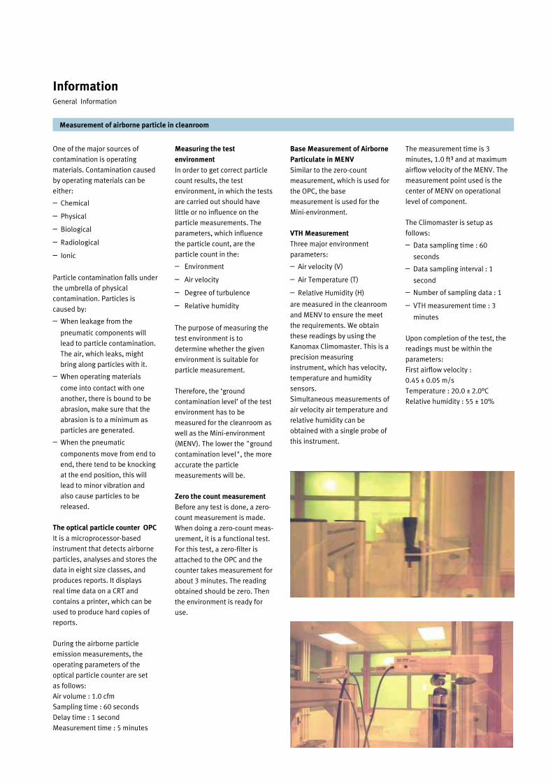
One of the major sources of
contamination is operating
materials. Contamination caused
by operating materials can be
either:
– Chemical
– Physical
– Biological
– Radiological
– Ionic
Particle contamination falls under
the umbrella of physical
contamination. Particles is
caused by:
– When leakage from the
pneumatic components will
lead to particle contamination.
The air, which leaks, might
bring along particles with it.
– When operating materials
come into contact with one
another, there is bound to be
abrasion, make sure that the
abrasion is to a minimum as
particles are generated.
– When the pneumatic
components move from end to
end, there tend to be knocking
at the end position, this will
lead to minor vibration and
also cause particles to be
released.
The optical particle counter OPC
It is a microprocessor-based
instrument that detects airborne
particles, analyses and stores the
data in eight size classes, and
produces reports. It displays
real time data on a CRT and
contains a printer, which can be
used to produce hard copies of
reports.
During the airborne particle
emission measurements, the
operating parameters of the
optical particle counter are set
as follows:
Air volume : 1.0 cfm
Sampling time : 60 seconds
Delay time : 1 second
Measurement time : 5 minutes
The measurement time is 3
minutes, 1.0 ft³ and at maximum
airflow velocity of the MENV. The
measurement point used is the
center of MENV on operational
level of component.
The Climomaster is setup as
follows:
– Data sampling time : 60
seconds
– Data sampling interval : 1
second
– Number of sampling data : 1
– VTH measurement time : 3
minutes
Upon completion of the test, the
readings must be within the
parameters:
First airflow velocity :
0.45 ± 0.05 m/s
Temperature : 20.0 ± 2.0°C
Relative humidity : 55 ± 10%
Measuring the test
environment
In order to get correct particle
count results, the test
environment, in which the tests
are carried out should have
little or no influence on the
particle measurements. The
parameters, which influence
the particle count, are the
particle count in the:
– Environment
– Air velocity
– Degree of turbulence
– Relative humidity
The purpose of measuring the
test environment is to
determine whether the given
environment is suitable for
particle measurement.
Therefore, the ‘ground
contamination level’ of the test
environment has to be
measured for the cleanroom as
well as the Mini-environment
(MENV). The lower the "ground
contamination level", the more
accurate the particle
measurements will be.
Zero the count measurement
Before any test is done, a zero-
count measurement is made.
When doing a zero-count meas-
urement, it is a functional test.
For this test, a zero-filter is
attached to the OPC and the
counter takes measurement for
about 3 minutes. The reading
obtained should be zero. Then
the environment is ready for
use.
Base Measurement of Airborne
Particulate in MENV
Similar to the zero-count
measurement, which is used for
the OPC, the base
measurement is used for the
Mini-environment.
VTH Measurement
Three major environment
parameters:
– Air velocity (V)
– Air Temperature (T)
– Relative Humidity (H)
are measured in the cleanroom
and MENV to ensure the meet
the requirements. We obtain
these readings by using the
Kanomax Climomaster. This is a
precision measuring
instrument, which has velocity,
temperature and humidity
sensors.
Simultaneous measurements of
air velocity air temperature and
relative humidity can be
obtained with a single probe of
this instrument.
Measurement of airborne particle in cleanroom
Information General Information

Information General Information
The principle of measuring contamination level of pneumatic components
Introduction
Basically there are two different
measuring principles how to
assess the clean room suitability
of operating materials. One
principle is to localize the particle
source and to measure the
particle emission directly at its
source.
Another principle is to assess the
total particle emission, by
measuring the average particle
emission in the space
surrounding the operating
material.
The direct Measurement
Principle
Applying the direct measurement
the specimen is operated inside a
clean room or mini environment.
There should be laminar, vertical
air flow around the specimen.
While the specimen is operated
a particle counter with a
movable measurement probe is
used to screen the entire
product for sources of particles.
Subsequently, the particle
emission is measured for 100
minutes at every particle
source, which has been located
before, in order to establish the
particle emission behavior.
The major advantage of this
principle is that it can be
applied to operating equipment
of almost any size.
Furthermore, it provides some
information about the particle
distribution and concentration
around the operating material.
This measurement principle is
described in detail in the VDI
2083-8 guideline.
The average Measurement
Principle
Using the average
measurement principle, the
specimen is operated inside a
container. The container is then
supplied with a defined volume
of clean dry air.
Simultaneously, the particle
emission is measured inside
the container, by using an
optical particle counter. All air,
which does not flow through
the particle counter, is release
through an exhaust opening. In
order to get the measurement
results, the ration between the
exhaust air and the amount of
air flowing through the particle
counter has to be known.
The major disadvantages of
this method are that the result
largely depends on the
placement of the measurement
probe inside the container as
the particle emission is not
necessarily consistent.
This makes the measurement
principle also very unsuitable for
measuring larger operating
materials, as the particle
emission get more inconsistent
inside of larger containers.
The advantage of this method is
that it allows a direct comparison
among several test specimen.
Furthermore, it is a lot easier to
handle.
There is no guideline available
from any independent
organization, such as ISO, VDI,
DIN, FDA etc., describing this
measurement principle.
How does FESTO measure?
FESTO decided to apply the direct
measurement method, as this
measurement allows the user to
gain information about the
highest particle concentration
around the product. Furthermore,
this measurement method is
described in the VDI-2083-8
guideline, which gives FESTO the
possibility to have a neutral
reference for the measurements.
The Direct Measurement
Principle
The Average Measurement
Principle

Information Festo Cleanroom project
The cleanroom project initiated
by Festo is a collaboration among
Fraunhofer Institute for
Manufacturing Engineering and
Automation in Germany, Nanyang
Polytechnic (NYP) of Singapore
and Festo Singapore.
The objective is to work together
in the field of particle emission of
Festo products.
Furthermore, it is Festo’s
intention to improve the
experience in the field of particle
measurements, contamination
control as well as cleanroom
applications in general.
Cleanroom environment
The cleanroom environment in
Nanyang Polytechnic is ISO
Class 6 cleanroom. The design
of this cleanroom is shown.
This is a cleanroom typical
layout.
This is a “ballroom” type
cleanroom with the area of
120 m2. The air flows in a
unidirectional way from a
ceiling of High Efficiency
Particular Air (HEPA) filters
down to the floor of the
cleanroom. The return air
passes through a return air
plenum in the Grey Room. The
Grey Room, which is located
just beside the cleanroom,
where it is used for service.
Festo cleanroom project - A collaboration among 3 parties
Floor
Return Air
Plenum
CleanroomGrey Room
Utility andEquipment
Chase
Supply Air from Fans
Window
PanelReturn
Air
Ceiling
HEPA
Floor
Return Air
Plenum
CleanroomGrey Room
Utility andEquipment
Chase
Supply Air from Fans
Window
PanelReturn
Air
Ceiling
HEPA
We’re doing the measurement
according the VDI 2083-8
guideline which is described on
page 82 and the following
pages. Fraunhofer Institute
approved this measurement
principle and attested this in a
‘Certificate of qualification’.
The certification covers: The
support for the performance of
testing the cleanroom suitabil-
ity of pneumatic components of
the company Festo AG & Co.
Festo’s cooperation with
Fraunhofer of Germany and
Nanyang Polytechnic of
Singapore
The cleanroom environment in
Nanyang Polytechnic of
Singapore

Mini-environment (MENV)
A Class 1 clean Mini-Environment
(MENV) is used within a clean-
room to provide the high level of
protection to products against
contamination and ESD events.
The specification of MENV is
shown. This MENV is a cleanroom
test cabinet with one clear
antistatic front panel and three
side panels. The dimension of
MENV is 1.2m x 0.6m internal
area and with 2.2m height. In
order to achieve high cleanliness
class, Ultra Low Penetration Air
(ULPA) Fan Filter Unit (99.9995%
efficiency on 0.12 micron) is
installed on the ceiling of the
MENV. The unidirectional supply
of air flows vertically from the Fan
Filter Unit (FFU), and the air
velocity can be adjusted up from
0.2 m/s to 0.6 m/s.
Optical Particle Counter
The LASAIR 210 OPC is used to
detect the concentration of
particles. The flow volume of this
counter is 1.0 CFM (cubic foot per
minute) or 28.3 liters per minute.
The counter is able to detect
particle size from 0.2 µm to 5.0
µm. The particle counter has
eight channels.
The setting of OPC is:
– Data Sampling Time: 60
seconds
– Data Sampling Interval: 1
second
– Measurement Time: 120
minutes
Flow Meter
The flow meter – Model 6521
Climomaster is used to measure
the airflow parameters.
Simultaneous measurements of
air velocity, air temperature and
relative humidity can be obtained
with a single probe of this
precision instrument.
The setting of flow meter is
– Data Sampling Time: 60
seconds
– Data Sampling Interval: 1
second
– Number of Sampling Data: 1
– Measurement Time: 3 minutes
Test procedure of Festo cleanroom components
Information Festo Cleanroom project
Summary specification of MENV
Vertical Laminar
Flow
1200 x 600 mm
ISO Class 3
0 … 0.6 m/s
infinitely
adjustable
800 … 1000 lux
Aluminium
Clear Front
Cover
230 V, single
phase 50 Hz
Design:
Internal
Dimensions:
Cleanliness:
Air Velocity:
Light
Intensity:
Main Body:
Front Design:
Power Supply:
In accordance with the US FED-
STD-209E, a cleanroom is
classified to be of Class 1 if only
one particle of the size of 0.5
µm or larger can be found in a
reference volume of one cubic
foot of the first air (filtered air
supplied).
In accordance with the ISO
14644-1, a cleanroom is
classified to be of Class 3 if only
35 particles of the size of 0.5
µm or larger can be found in a
reference volume of one cubic
meter of the first air (filtered air
supplied).
There is no tabletop installed in
the mini environment. Instead a
removable clean room trolley
with perforated tabletop is
used. The height of the trolley/
table is approx. 1.10 m
Measuring Instrument
The two most important test
instruments for the particle
measurements are Optical
Particle Counter (OPC) and Flow
Meter.
A LASAIR 210 Optical Particle
Counter, manufactured by
Particle Measuring Systems
Incorporation, and Model 6521
Climomaster (airflow, relative
humidity and temperature
measurement), manufactured
by KANOMAX Japan incorpora-
tion, are used in the particle
measurements.
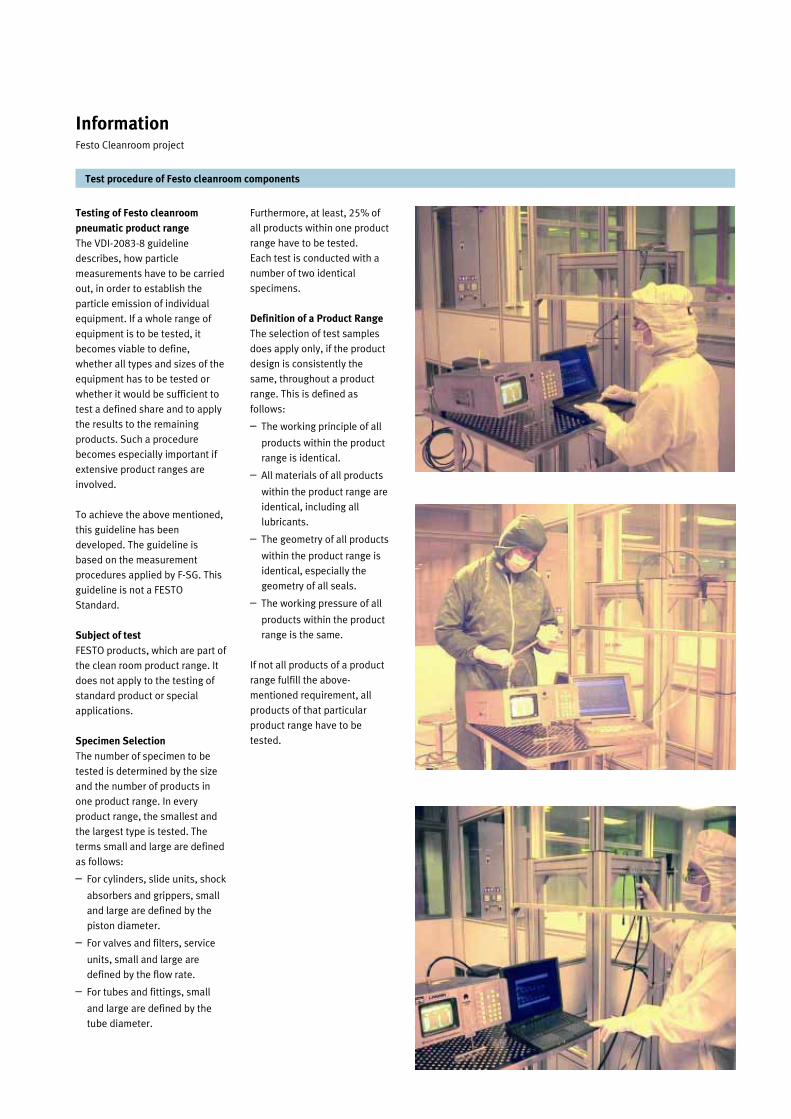
Testing of Festo cleanroom
pneumatic product range
The VDI-2083-8 guideline
describes, how particle
measurements have to be carried
out, in order to establish the
particle emission of individual
equipment. If a whole range of
equipment is to be tested, it
becomes viable to define,
whether all types and sizes of the
equipment has to be tested or
whether it would be sufficient to
test a defined share and to apply
the results to the remaining
products. Such a procedure
becomes especially important if
extensive product ranges are
involved.
To achieve the above mentioned,
this guideline has been
developed. The guideline is
based on the measurement
procedures applied by F-SG. This
guideline is not a FESTO
Standard.
Subject of test
FESTO products, which are part of
the clean room product range. It
does not apply to the testing of
standard product or special
applications.
Specimen Selection
The number of specimen to be
tested is determined by the size
and the number of products in
one product range. In every
product range, the smallest and
the largest type is tested. The
terms small and large are defined
as follows:
– For cylinders, slide units, shock
absorbers and grippers, small
and large are defined by the
piston diameter.
– For valves and filters, service
units, small and large are
defined by the flow rate.
– For tubes and fittings, small
and large are defined by the
tube diameter.
Furthermore, at least, 25% of
all products within one product
range have to be tested.
Each test is conducted with a
number of two identical
specimens.
Definition of a Product Range
The selection of test samples
does apply only, if the product
design is consistently the
same, throughout a product
range. This is defined as
follows:
– The working principle of all
products within the product
range is identical.
– All materials of all products
within the product range are
identical, including all
lubricants.
– The geometry of all products
within the product range is
identical, especially the
geometry of all seals.
– The working pressure of all
products within the product
range is the same.
If not all products of a product
range fulfill the above-
mentioned requirement, all
products of that particular
product range have to be
tested.
Test procedure of Festo cleanroom components
Information Festo Cleanroom project

Test procedure of Festo cleanroom components
Information Festo Cleanroom project
Step 2: Testing of instrument
It is also important to note that
each time before the tests are
made the required zero count
measurement, base
measurement and VTH
measurement are carried out as
follows:
– OPC airflow
– OPC laser-reference
– OPC zero-particle-count
(measurement time: 3
minutes, with zero-filter
attached)
– MENV air flow velocity
(maximum power of FFU)
– Relative humidity
(measurement time: 1
minute with measurement
intervals of 1 second)
– Airflow-velocity
(measurement time: 1
minute with measurement
intervals of 1 second)
– Temperature (measurement
time: 1 minute with
measurement intervals of 1
second)
– Base measurements of
MENV, airborne particulate
contamination
(measurement time 3
minutes, 1.0 cft, at maximum
air flow velocity of MENV,
measurement point in the
center of MENV on
operational level of
component)
Standard operation procedure
(SOP) are done before actual
commencement of the test. These
procedure are standard
regardless of the type of test
specimen.
Step 1: Inward transfer of test
samples
Before any test is done, the
components need to be prepared.
The preparation for the
cleanroom suitability assessment
involves the cleaning of these
components according to the
Festo-SG guidelines "Operating
Conditions for Cleanroom Tests".
The cleaning sequence is outlined
below:
– Decontamination of test
samples (inner and outer parts)
with Isopropanol saturated
wipers and ultrapure
compressed dry air.
Sequence:
– Pre-cleaning by blowing
component surface with
ultra-pure compressed dry
air.
– Cleaning of component
surface using pre-saturated
wipers containing a blend of
Isopropyl alcohol.
– Final cleaning by blowing
component surface with
ultra-pure compressed dry
air.
– Bringing the test samples into
the CR-environment and MENV
– Arranging the test samples
(with gloves, intermediate
decontamination, cleaning)
Step 5: Classification
measurements
During the test, the airborne
particle generated by the
component is measured using a
discrete particle counter (DPC).
– Particle size is 0.2 mm, 0.7
mm, 1.0 mm, 2.0 mm, 3.0
mm, and 5.0 mm are
selected.
– Measurement time:
– standard-classification: 100
minutes (according to VDI
2083 part 8) at the
measurement points that
were found during the
Localization measurements
– lifecycle-test: several days,
up to months
– Documentation of
measurements points (sketch
or photograph)
Step 6: Statistical evaluation
Evaluation according to guideline
VDI 2083 part 8
Step 7: Visual inspection
Visual inspection of tested
components (e.g. wear and tear,
deposition of lubricants and
particles, product failure…)
Step 8: Classification
Classification of test specimen
according to statistical evaluation
and visual inspection (see
guideline VDI 2083 part 8)
Step 3: Adjustment of the
operating parameters for the
test sample
After mounting the component
on a test support fixture, it is
ready for the test.
– Adjustment of operating
parameters e.g. cushioning
on actuator, speed of
actuator
– Statement about performed
duty cycles at the time of
testing
– Documentation of
adjustment (sketch or
photograph)
Step 4: Localization
measurements
Determination of points of
highest concentrations of
particle emission (according to
VDI 2083 part 8)
– Coarse localization
measurement
– Localization measurement

– Description of measurement
points
– Sketches or photographs
– References to applied
standards and guidelines
– Documentation
– Particle concentration at
measurement points
– Graphical visualization of
particle emission
– Interpretation of results and
conclusion
– Classification related to
applied standards/
guidelines
– General Assessment
Potential for optimization
Operating condition for testing
Festo components in
cleanroom
Operating Conditions are
defined by Festo-SG
individually for different Festo
products. The guidelines for
product range, cylinders, rotary
actuators, valves, grippers and
service units are listed in page
88 and 89.
Preparing compressed air for
testing Festo components in
cleanroom
– Compressor
– Air storage
– Refrigeration dryer
– Prefilter regulator of 40 µm
– Fine filter 1 µm
– Micro filter 0.1 µm
Test procedure of Festo cleanroom components
Information Festo Cleanroom project
Testing of DSNU-…-RR-SA cylinder
Testing of ADVU-…-RR-SA cylinder
Testing of CDN-…-RR-SA cylinder
Step 9: Documentation
Complete documentation
should contain the following
information
– Title, Date , Place of test
– Person responsible
– Test environment
– Operating Parameters
– Temperature
– Relative humidity
– Air flow velocity
– Particulate concentration
in test environment
– Measurement technology
– Type
– Model
– Detection limits
– Air flow
– Description of sample
technique
– Sample Characteristics
– Type
– Supplier
– Serial Number
– Component description
– Operating parameters of
components
– Break-in load
– Running-in time
– Mounting position
– Operating frequency
– Attached load
– Supply (air- power supply
etc.)
Air 40 µm 1µm 0.1 µminlet
1 2

Operating conditions for
Cleanroom tests - Cylinders
Pneumatic linear actuators:
– Single- and double-acting
cylinders with and without
piston rods
– Guide and slide units
Each test is conducted with a
number of two identical
specimens. The supply air should
be clean dry air. This clean dry air
is filtered with micro-filter which
eliminates 99.9999% of particles
bigger than 0.01 mm. The
operating pressure for all
samples is 6.0 ± 0.3 bar or
maximum pressure, for specimen,
whose operating pressure is less
than 6.0 bar. The ambient
temperature should be 20 ± 2 °C.
The medium temperature should
not exceed 30 °C. The max.
speed is defined as 0.2 m/s for all
kinds of cylinders. The speed is
adjusted by means of one-way
flow control valves, installed as
close as possible to the cylinder
ports. The adjustment is done in a
way, that the piston safely
reaches its end-position.
Tables below shows: A pulse/
interval ratio of 1:1 should be
used for all frequencies. On the
condition of the max. speed
0.2m/s, the different frequencies
are defined due to different
piston diameter., they are shown
as following table. The
frequencies can be adjusted by
changing PLC programming.
Whenever possible compression
fittings with sealing rings in
combination with polyurethane
tubes should be used for the for
the air supply. This is to ensure
minimum leakage.
For all cylinders with piston rod
the mounting position is defined
as horizontal, with the supply
ports on the bottom of the
sample, except for DGPL cylinder
and slide units. For the latter the
port orientation is determined by
the product design. Cylinders
without piston rod are tested in
horizontal and vertical mounting
positions. If possible, standard
mounting-accessories should be
used. To minimize turbulence, the
mounting accessories should
disturb the airflow as little as
possible.
Prior to every measurement the
supply pressure must be
checked. The pressure should be
6.0 +/- 0.3 bar.
Acoustic/visual/tactile check
under test conditions to see that
test specimens are operating
correctly and that there is not
sticking, jamming, stopping short
of end positions, jerky motion,
bottoming-out of cushioning or
leaks which can be felt or heard.
As any leakage leads to high
emission of particles, there
should be no detectable leakage.
If there is any leakage detected,
the test should be aborted.
As the amount of particles,
emitted by a cylinder, is not
constant throughout its service
life, particle measurements have
to be undertaken at different
stages of the service life.
Particle measurement should be
carried out after 20,000 duty
cycles have been completed
In the case of cylinders with
protection against torsion,
testing should be carried out
using 20% of the maximum
moment.
Suction rate at vacuum port
Conditions at which Festo cleanroom components are tested
Information Festo Cleanroom project
The end position cushioning
should be adjusted in such a
way that there is no hard
metallic impact in the end
positions and the piston does
not rebound.
For test sample of cylinders, the
following stroke lengths are
chosen for the various piston
rods as:
Cleanroom test of cylinders
should be carried out under
different load conditions.
However, because of short of
time, cylinders are only tested
under the condition of
horizontally mounted with a
load.
Table below shows: Load
parameters for piston-rod
cylinders without guide or
protection against torsion.
Type Piston diameter [mm]
Frequency [Hz]
6 to 8 2
10 to 20 1.5
25 to 50 1.0
63 to 100 0.3
Rodless cylinders
8 to 100 0.5
Piston rod cylinder
Piston diameter [mm]
Stroke length *[mm]
6 to 8 20 or max. stroke
10 to 20 50 or max. stroke
25 to 32 100 or max. stroke
40 to 50 200 or max. stroke
63 to 100 300 or max. stroke
Ø [mm] Additional Mass [kg] (3% theoretical effective
force)
Moment due to additional load [Nm]
M = m x g x s
6 0.057 0.0168
8 0.091 0.0357
10 0.145 0.0711
12 0.225 0.1324
16 0.360 0.2825
20 0.570 0.5592
25 0.910 1.1159
32 1.450 2.2759
40 2.225 4.4145
50 3.600 8.8290
63 5.700 16.7751
80 9.100 26.7813
100 14.500 42.6735
Piston Diameter [mm]
Additional Mass [kg] (20% theor. effective force)
8 0.570
10 0.910
12 1.450
16 2.250
20 3.600
25 5.700
32 9.100
40 14.500
50 22.500
63 36.000
80 36.000
100 36.000
Ø [mm] Min. vacuum flowrate [l/min]
Recommend Vacuum generator [Type]
12...25 23 VN-07-L-…
32...50 35 VN-07-L-…

Conditions at which Festo cleanroom components are tested
Information Festo Cleanroom project
Operating conditions for
cleanroom tests - Valves
Pneumatic digital switching
valves as follows:
– Mechanically-actuated/
manually-operated digital
switching valves
– Pneumatically-actuated digital
switching valves
– Solenoid-actuated digital
switching valves
Each test is conducted with a
number of two identical
specimens. The supply air should
be clean dry air. This clean dry air
is filtered with micro-filter which
eliminates 99.9999% of particles
bigger than 0.01 µm. The
operating pressure for all
samples is 6.0 +/- 0.3 bar or
maximum pressure, for specimen,
whose operating pressure is less
than 6.0 bar. The ambient
temperature should be 20 +/- 2
degree Celsius. The medium
temperature should not exceed
30 degree Celsius.
Table shows: A pulse/interval
ratio of 1:1 should be used for all
frequencies. The additional
volumes should be connected to
the outputs of the test specimens
via pieces of tubing and
appropriate fittings.
The ambient temperature should
be 20 ± 2 °C. The medium
temperature should not exceed
30 °C. A minimum flow rate of 125
l/min is necessary for correct
operation. However, flow meas-
urement devices such as flow
sensors or flowmeters are need to
ensure this minimum flow rate.
The switch frequency for on-off
valves are 2 Hz. The mounting
position for is vertical ±5°. The
operating voltage for solenoid
actuated on-off valve is set as 24
± 10% V DC. For manual conden-
sate drain, plastic tubing is con-
nected to the barb fitting. This is
to ensure minimum leakage.
Prior to every measurement the
supply pressure must bechecked.
The pressure should be 7.0 ± 0.3
bar. Acoustic/visual/tactile check
under test conditions to see that
test specimens are operating
correctly. As any leakage leads to
high emission of particles, there
should be no detectable leakage.
If there is any leakage detected,
the test should be aborted.
Although, it should be avoided
that any medium such as air or
lubricant is leaking out of the
pneumatic system, it cannot be
entirely avoided if pneumatic
actuators are applied. In order to
minimize harmful contamination,
the medium, mostly compressed
air or nitrogen, should be dried
and filtered accordance to ISO
8573-1, Class 1.
Compressed Air Quality Standard:
ISO8573-1
Ensure that the tubing connect
does not increase the size of
the additional volume by more
than 20%. Tube size of supply
line with maximum length of
100 cm.
Whenever possible
compression or barbed fittings
in combination with
polyurethane tubes should be
used for the for the air supply.
This is to ensure minimum
leakage. For those valves that
barbed fittings are not
available, push-in fittings are
used in the test.
Acoustic/visual/tactile check
under test conditions to see
that test specimens (and pilot
valves) are operating correctly
and that there is no failure to
switch, sticking, incomplete
venting of outputs or leaks
which can be felt or heard. Any
departures from normal
operation should be
documented.
As any leakage leads to high
emission of particles, there
should be no detectable
leakage. If there is any leakage
detected, the test should be
aborted.
Operating conditions for
cleanroom tests - Air
preparation units
– Filter
– Filters
– Fine and micro filters
– Pressure regulators
– Manual on-off valve
– Solenoid actuated on-off
valve
– Soft start valves
The specifications of test
specimens are as:
– Pressure range: 0 to 7 bar
– Degree of filtration: refer to
filter type filter or micro-filter
connected
– Filter type LF or LFMA/B with
connector plates are used
– Pressure gauge connections
– Manual condensate drain
The supply air should be clean
dry air. This clean dry air is
filtered with micro-filter which
eliminates 99.9999% of
particles bigger than 0.01 mm.
The compressed air regulator is
connected with micro-filter to
adjust the pressure. The
working pressure during the
test is 7 bar. The air
preparation unites are
measured under the following
conditions:
– Primary pressure (input
pressure) p1=7 bar
– The controlled pressure
(output pressure) p2= 6 bar
– Pressure drop p=1 bar Valve port size Switching frequency [Hz]
Additional volume [ml]
Inner diameter of tube [mm]
M3 3 2 3
M5 3 10 3-4
M7 3 10 4-6
1/8” 3 10 4-6
1/4” 3 25 4-6
3/8” 2 25 6-9
1/2” 2 50 6-9
3/4” 1 100 13
1 1 400 13
Class Dust Oil
[um] [mg/m³] [DTP] [g/m³] [mg/m³]
1 0.1 0.1 -70 0.003 0.01
2 1 1 -40 0.12 0.1
3 5 5 -20 0.88 1
4 15 8 +3 6.0 5
5 40 10 +7 7.8 25
6 - - +10 9.4 -
7 - - - - -
Water

In all automation processes,
pneumatics plays an important
role. This is the same for
cleanroom, pneumatics are
used in cleanroom for the
following reasons:
– Automation of production se-
quence with pneumatics
– Lower space requirements with
pneumatics
– Lower levels of contamination
with pneumatics
– Laminar flow virtually unim-
paired by pneumatics
Benefits
– Avoidance or reduction of
particle emissions both with
stationary components and in
an operating sequences
– Minimization of disturbance
factors affecting laminar flow
– Counter measures against pos-
sible environmental influences
(e.g. acids, aggressive media)
Difference in comparison
with standard products
The following list is the difference
between the standard products
and those used in cleanroom.
– Generally suitable for
unlubricated operation
– Cleanroom compatible grease
used when necessary
– Cleanroom compatible
markings
– Ducted exhaust ports and
connections for air breather
ports
– Extraction by means of vacuum
where necessary
Production sequence of Festo
cleanroom product range
Basically, the manufacturing of
clean room pneumatics is not any
different from the design of any
other pneumatic component. It is
just, that special care is taken, to
avoid any kind of contamination
caused by the product.
Design office
Firstly the design of a standard
product is modified with a view to
cleanroom compatibility.
Assembly
All products are assembled
outside the cleanroom, according
to the standard assembly
procedures. In very special cases,
cleanroom grease is applied
instead of the standard lubricant.
Testing
Just as any standard product,
cleanroom products are tested,
concerning their functionality.
There is no particle emission test
conducted for every product.
Cleaning
Before packing all products are
cleaned under cleanroom
condition of ISO Class 7. The
cleaning is done either by means
of an ultrasonic bath or with
isopropanol wipers.
Packaging
Packaging is done in antistatic
plastic bags. Whereby each
product is double packed and
sealed. Just as the cleaning, the
packaging takes place under
cleanroom condition of ISO Class
7. When the product is ready for
shipment, it is transferred out of
the cleanroom through an airlock.
Basic principle of Festo
cleanroom product range
It is known that there isn’t
a standard or guideline for
cleanroom product design
available. In order to develop
products for cleanroom
application, we mainly base on
the principle of “avoiding
cleanroom contamination by
preventing particles generated
from the components”.
This principle includes the
following three aspects:
– Non-contaminant release
very low leakage construc-
tion
– Non-contaminant generation
special material, surface
treatment and special lubri-
cation specification
– Non-contaminant in produc-
tion processes – component
cleaning and double bag
packaging
The above three aspects can be
achieved for cleanroom com-
patibility by modifying our stan-
dard products to cleanroom
products with some special
features. The general principle
is to design an additional vac-
uum suction port so that air
leakage during operation can
be sucked back and extracted
by vacuum.
Non contaminants releasing:
Drives
– Air leakage from the piston
rod is sucked back and
extracted by vacuum via a
additional vacuum suction
port on the front cap or
barrel (housing)
– Leak-free design principle
Valves
– Exhaust air from both main
valve and pilot valve are
released via common ex-
haust ports
– Breather air from underside
of piston is removed via
exhaust ports
– Leak-free design principle
Air preparation unit
– Regulator: vent air in the
bonnet is sucked through a
vacuum connection on an
additional ring
– Air filter: drain is discharged
from cleanroom via drain
guide port
Grippers
– Air leakage is extracted via
vacuum suction port
Vacuum and other components
– Exhaust air is ported to the
outside of cleanroom
– Shock absorber: replace-
ment of a new housing with a
vacuum port
– Fittings & tubing: air leakage
is minimized by using the
barbed fittings
Non contaminant generating
Piston rod is made of corrosion
resistant steel
Non contaminant in production
process
– Cleaning individual compo-
nents by ultrasonic cleaning
bath
– All components are cleaned
and assembled in a
cleanroom
– Functional test in a
cleanroom
– Double-packed in plastic
bags in a cleanroom
Benefits of using Festo cleanroom components
Information Festo Cleanroom project

Festo Worldwide
Sales and Service Network—International
Festo Worldwide
Algeria
Argentina
Australia
Austria
Bahrain
Bangladesh
Belarus
Belgium
Bolivia
Brasilia
Bulgaria
Canada
Chile
China
Columbia
Costa Rica
Croatia
Cyprus
Czech Republic
Denmark
Dominican Republic
Ecuador
Egypt
El Salvador
Estonia
Finland
France
Germany
Great Britain
Greece
Guatemala
Honduras
Hong Kong
Hungary
Iceland
India
Indonesia
Iran
Ireland
Israel
Ivory Coast
Italy
Japan
Jordan
Kenya
Kuwait
Latvia
Lebanon
Lithuania
Malaysia
Malta
Morocco
Mexico
Myanmar
Netherlands
New Zealand
Nicaragua
Nigeria
Norway
Oman
Pakistan
Paraguay
Peru
Philippines
Poland
Portugal
Republic Korea
Romania
Russia
Saudi Arabia
Singapore
Slovakia
Slovenia
South Africa
Spain
Sri Lanka
Sweden
Switzerland
Syria
Taiwan
Thailand
Tunisia
Turkey
Ukraine
United Arab Emirates
United States of America
Uruguay
Venezuela
Viet Nam
Yugoslavia

Festo Worldwide
The Company
Festo Group:
Year of foundation:
Name of company:
Board of Directors:
Supervisory Board:
Number of employees (Festo Group):
Trainees (in Germany):
Locations in Germany:
Number of Festo companies:
Number of agencies:
Service world-wide:
R&D investment as % of turnover:
Quality certificates held by Festo AG & Co.:
Environmental certificates held by Festo AG & Co.:
Quality and environmental certificates:
Festo customers:
Festo AG & Co.
Festo Didactic GmbH & Co.
Beck IPC GmbH
FCC GmbH Marketing, Werbung, Messen
Festo AG & Co.
1925
Festo AG & Co.
Personally responsible shareholder:
Festo Aktiengesellschaft
Dr. Wilfried Stoll (Chairman)
Dr. Ekkehard Gericke
Dipl.-Ing. Rudi Menrad
Dr. Thomas Rubbe
Dr. Eberhard Veit
Dr. Ulrich Walker
Dr. h.c. Kurt Stoll (Chairman)
Dr. Mark Binz
Dipl.-Kfm. Manfred Kalmbach
10,050 world-wide
6.2 % of workforce (in Germany)
Festo HQ in Esslingen Berkheim:
Festo AG & Co.
Postfach
73726 Esslingen
Ruiter Straße 82
73734 Esslingen
Customer Service Center, St. Ingbert-Rohrbach
Cylinder production works, St. Ingbert-Rohrbach
Festo Saar Learning Center, St. Ingbert-Rohrbach
52 independent Festo companies with over 250 branch offices
Authorised Festo agencies in a further 36 countries
In 176 countries
6,5 %
DQS certificate as per DIN ISO 9001 since 1990
DQS certificate as per VDA 6.1 since 1999
DQS certificate as per VDA 6.4 since 2000
Best Factory Award 1997
Eco certificate as per EMAS since 1996
Eco certificate as per ISO 14001 since 2000
41 companies world-wide certified as per ISO 9001/9002.
held by Festo companies One company certified as per ISO 14001.
Over 300,000 in 176 countries

Festo Worldwide
The History
History – An overview of Festo’s milestones 1956 Festo S.p.A. Milano, Italy Festo AG Zürich, Switzerland
1958 Festo S.A.R.L. Sarreguemines, France
1959 Festo Maschinenfabrik Ges.m.b.H. Vienna, Austria
1963 Festo Elgi Private Ltd. Coimbatore, India
1964 Festo AB Malmö, Sweden Festo Pneumatic Belgium S.P.R.L., Brussels, Belgium
1966 Festo Pty. Ltd. Melbourne, Australia
1967 Festo Pneumatic Holland B.V., Delfgauw, Netherlands
1968 Festo Ltd. Fleet, Great Britain Festo Ltd. Northhampton, Great Britain Festo Maquinas e Equipamentos Pneumaticos Ltda., Santo André, Brazil
1970 Festo Pneumatic ApS, Copenhagen, Denmark
1971 Festo Pneumatic S.A., Barcelona, Spain
1972 Festo Corporation, Hauppauge , USA
1973 Festo Ltd., Johannesburg, South Africa
1974 Festo Pneumatic S.A., Edo. De México, Mexico
1975 Festo Pneumatic S.K., Teheran, Iran
1976 Festo Pneumatic Ltd., Kowloon, Hong Kong
1977 Festo Inc., Toronto, Canada Festo Pneumatic S.A., Buenos Aires, Argentina Festo OY AB, Helsinki, Finland
1978 Festo Inc., Manila, Philippines
1979 Festo Pneumatic Sdn. Bhd., Kuala Lumpur, Malaysia Festo Co. Ltd., Taipei, Taiwan
1980 Festo Korea Co. Ltd., Seoul, Korea Festo Pte. Ltd., Singapore
1983 Festo Kft., Budapest, Hungary
1986 Festo Controls Pvt. Ltd., Bangalore, India Festo K.K., Yokohama, Japan Festo Autoamação, São Paulo, Brazil Festo Machinex (ab 1993 Festo Bulgaria EOOD), Sofia, Bulgaria
1987 Festo Ltd., Athens, Greece
1988 Festo RF 000, Moscow, Russia Festo Pnevmoavtomatic, Simferopol, Ukraine
1989 Festo Ltda., Bogotá, Colombia Festo Sp.z o.o., Warsaw, Poland Festo San. ve Tic. A.S., Istanbul, Turkey Festo PT, Jakarta, Indonesia 1990 Festo spol.sr.o., Prag, Chechnya Festo S.R.L., Bucharest, Romania
1991 Festo Ltd., Dublin, Ireland Festo Ltd. Auckland, New Zealand Festo Ukraina, Kiew, Ukraine Festo d.o.o., Zagreb, Croatia
1992 Festo Ltd., Bangkok, Thailand Festo d.o.o., Ljubljana, Slovenia
1993 Festo Bulgaria EOOD (bis 1993 Festo Machinex), Sofia, Bulgaria Festo UAB, Kaunas, Lithuania Festo Ltd., Shanghai, China
1994 Festo spol. s r.o., Bratislava, Slovakia
1995 Festo C.A., Maracaibo, Venezuela
1996 Festo OY AB Eesti Filiaal, Tallinn, Estonia
1997 Festo SIA, Riga, Latvia
2001 Festo Chile, Santiago, Chile

Notes
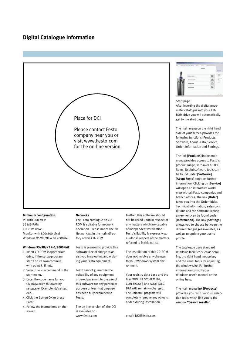
Digital Catalogue Information
Minimum configuration:
PII with 500 MHz
32 MB RAM
CD-ROM drive
Monitor with 800x600 pixel
Windows 95/98/NT 4.0/ 2000/ME
Windows 95/98/NT 4.0/2000/ME
1. Insert CD-ROM inappropriate
drive. If the setup-program
starts on its own continue
with point 5. If not…
2. Select the Run command in the
start menu.
3. Enter the code name for your
CD-ROM drive followed by
setup.exe. Example: d;\setup.
exe.
4. Click the Button OK or press
Enter.
5. Follow the Instructions on the
screen.
Networks
The Festo catalogue on CD-
ROM is suitable for network
operation. Please notice the file
Network.txt in the main direc-
tory of this CD- ROM.
Festo is pleased to provide this
software free of charge to as-
sist you in selecting and order-
ing your Festo equipment.
Festo cannot guarantee the
suitability of any equipment
ordered pursuant to the use of
this software for any particular
purpose unless that purpose
has been fully explained to
Festo.
The on line version of the DCI
is available on :
www.festo.com
Further, this software should
not be relied upon in respect of
any matters which are capable
of independent verification.
Festo's liability is expressly ex-
eluded in respect of the matters
referred to in this notice.
The installation of this CD-ROM
does not involve any changes
to your Windows system envi-
ronment.
Your registry data base and the
files WIN.IN1.SYSTEM.INI,
CON-FIG.SYS and AUOTEXEC.
BAT will remain unchanged.
The uninstall program will
completely remove any objects
added during installation.
email: [email protected]
Start page
After inserting the digital pneu-
matic catalogue into your CD-
ROM drive you will automatically
get to the start page.
The main menu on the right hand
side of your screen provides the
following functions: Products,
Software, About Festo, Service,
Order, Information and Settings.
The link [Products] in the main
menu provides access to Festo's
product range, with over 18.000
items. Useful software tools can
be found under [Software].
[About Festo] contains further
information. Clicking on [Service]
will open an interactive world
map with all Festo companies and
branch offices. The link [Order]
takes you into the Order folder.
Technical information, sales con-
ditions and the software license
agreement can be found under
[Information]. The link [Settings]
allows you to choose between the
different languages available, as
well as to update your user's
profile.
The catalogue uses standard
Windows facilities such as scroll-
ing, the right hand mouse key
and the usual tools for adjusting
the window size. For further
information consult your
Windows user's manual or the
online help.
The main menu link [Products]
provides you with various selec-
tion tools which link you to the
window “Search results”.
Place for DCI
Please contact Festo company near you or visit www.Festo.com for the on-line version.
Festo worldwide
Argentina Festo S.A. Edison 2392 RA-1640 Martinez Pcia. de Buenos Aires Tel. ++54 (0)11/47 17 82 14, Fax 47 17 82 15 E-mail: [email protected]
Australia Festo Pty. Ltd. P.O. Box 261 179-187 Browns Road Noble Park North VIC. 3174 Tel. ++61 (0)3/97 95 95 55, Fax 97 95 97 87 E-mail: [email protected]
Austria Festo Gesellschaft m.b.H. Lutzowgasse 14 A-1141 Wien Tel. ++43 (0)1/91 07 50, Fax 91 07 52 50 E-mail: [email protected]
Belgium Festo Belgium nv/sa Rue Colonel Bourgstraat 101 B-Brussel 1030 Bruxelles Tel. ++32 (0)2/702 32 11 Fax 726 90 11 E-mail: [email protected]
Brazil Festo Automacao Ltda. Rua Giuseppe Crespi, 76 Jardim Santa Emilia BR-04183-080 Sao Paulo-SP Tel. ++55 (0)11/69 69 95 00, Fax 69 47 73 11 E-mail: [email protected]
Bulgaria Festo Bulgaria EOOD Tintjava 15-17 BG-1113 Sofia Tel. ++359 (0)2/962 53 06, Fax 962 52 36 E-mail: [email protected]
Canada Festo Inc. 5300 Explorer Drive CON-Mississauga, Ontario L4W 5G4 Tel. ++1(0)905/624 90 00, Fax 624 90 01 E-mail: [email protected]
Chile Festo Chile Mapocho 1901 6500151 Santiago Tel. ++56 (0)2/6 98 46 55, Fax 6 97 07 96
China Festo (China) Ltd. 1156 Yunqiao Road Jinqiao Export Processing Zone 201206 Pudong, Shanghai, PRC Tel. ++86 (0)21/58 54 90 01, Fax 58 54 03 00 E-mail: [email protected]
Colombia Festo Ltda. Avenida Eldorado No. 98-43 CO-Santafe de Bogota D.C. Tel. ++57 (0)1/413 00 88, Fax 415 30 51
Croatia Festo d.o.o. Nova Cesta 181 HR-10 000 Zagreb Tel. ++385 (0)1/619 19 69, Fax 619 18 18 E-mail: [email protected]
Czech Republic Festo spol. s r.o. Pod Belarii 784 C2-143 00 Praha 4-Modrany Tel. ++420 (0)2/61 09 96 11, Fax 61 09 36 34 E-mail: [email protected]
Denmark Festo A/S Islevdalvej 180 DK-2610 Rødovre Tel.++4570211090 Fax 88 8110 E-mail: [email protected]
Singapore Festo Pte. Ltd. 6 Kian Teck Way SGP-Singapore 628 754 Tel. ++65 (0)6264 01 52, Fax 6261 10 26 E-mail: [email protected]
Slovakia Festo spol. sr. o. Gavlovicova ul.l SK-83103 Bratislava Tel. ++421 (0)7/44 25 02 68. Fax 44 45 38 76 E-mail: [email protected]
Slovenia Festo d.o.o. Ljubljana IC Trzin, Blatnica 8 SLO-1236 Trzin Tel. ++386 (0)1/530 21 00, Fax 530 21 25 E-mail: [email protected]
South Africa Festo (Pty.) Ltd. 22-26 Electron Ave. ZA-lsando 1600 Tel. ++27 (0)11/971 55 00, Fax 974 21 57 E-mail; [email protected]
Spain Festo Pneumatic, S.A. Avda.de la Gran Via, 159 (Poligono Gran Via Sur) E-08908 Hospitalet de Llobregat-Barcelona Tel. ++34 (9)3/261 64 00, Fax 261 64 20 E-mail: [email protected]
Sweden Festo AB Stillmansgatan 1 S-20021 Malmo Tel. ++46 (0)40/38 38 00, Fax 18 97 68 E-mail: [email protected]
Switzerland Festo AG Moosmattstrasse 24 CH-8953 Dietikon/Zurich Tel. ++41 (0)1/744 55 44, Fax 744 55 00 E-mail: [email protected]
Taiwan Festo Co.. Ltd. 9, Kung 8th Road Linkou 2nd Industrial Zone, 244 Taipei Hsien, Taiwan, ROC Tel. ++886 (0)2/2601 92 81, Fax 2601 92 87 E-mail: [email protected]
Thailand Festo Ltd. 67/1 Phaholyothin Road. Moo 6, Klong 1, Amphur Klong Luang Pathumthani 12120. Thailand Tel. ++66 (0)2/901 88 00, Fax 901 88 33 E-mail: [email protected]
Turkey Festo San. ve Tic. A.S. Fahrettin Kerim Gokay Cad. No. 281, Ozcelik han - Sahray cedid TR-81080 Kadikoy/lstanbul Tel. ++90 (0)216/411 44 66, Fax 411 44 74 E-mail: [email protected]
Ukraine Festo Ukraina ul. Borissoglebskaja, 11 UA-254070 Kiev Tel. ++380 (0)44/239 24 34, Fax 463 70 96 E-mail: [email protected]
USA Festo Corporation 395 Moreland Road USA-Hauppauge, N.Y. 11788 Tel. ++1 (0)631/435 08 00. Fax 435 80 26 E-mail: [email protected]
Venezuela Festo C.A. Av. 23, Esquina calle 71, No. 22 - 62 Maracaibo. Edo. Zulia Tel. ++58 (0)261/7 59 09 44 , Fax 7 59 04 55 E-mail: [email protected]
Estonia Festo OY AB Eesti Fillaal Turi 10 EE-11313 Tallinn Tel. ++372(0)6/5016 40, Fax 55 81 26 E-mail: [email protected]
Finland Festo OY Makituvantie 9 FIN-01511 Vantaa Tel. ++358 (0)9/87 06 51, Fax 87 06 52 00 E-mail: [email protected]
France Festo E.U.R.L. 5, rue Montgolfier F-93116 Rosny-sous-Bois Cedex Tel. ++33 (0)1/49 35 23 23, Fax 49 35 23 33 E-mail: [email protected]
Germany Festo AG & Co. Postfach D-73726 Esslingen Ruiter Strasse 82 D-73734 Esslingen Tel. ++49 (0)711/347-0, Fax 347-2144 E-mail: [email protected]
Great Britain Festo Limited Automation House Harvest Crescent, Ancells Business Park GB-Fleet, Hampshire 6U13 8XP Tel. ++44 (0)12 52/77 50 00, Fax 77 50 01 E-mail: [email protected]
Greece Festo Ltd. 40 Homosternas Av. GR-11853 Athens Tel. ++30 (0)1/34 12 90 04, Fax 341 29 05 E-mail: [email protected]
Hong Kong Festo Ltd. Unit C&D, 7/F, Leroy Plaza, 15 Cheung Shun Street. Cheung Sha Wan, Kowloon, Hong Kong Tel. ++852/ 27 43 83 79. Fax 27 86 21 73 E-mail: [email protected]
Hungary Festo Kft. Becsi ut 100 H-1034 Budapest Tel. ++36 (0)1/250 00 55, Fax 250 15 93 E-mail: [email protected]
India Festo Controls Private Ltd. Plot No. 226, Bommasandra Industrial Area IND-Bangalore 562 158 Tel. ++91 (0)8110/3 33 59, Fax 3 20 58 E-mail: [email protected]
Indonesia PT. Festo Jl. Sultan Iskandar Muda No. 68 (Arteri Pondok Indah) Jakarta 12240 Tel. ++62 (0)21/2750 7900, Fax 726 73 86 E-mail: [email protected]
Iran Festo Pneumatic S.K. Kh. Ramsar, Ko. Behbahan No. 1 IR-15 Teheran Tel. ++98 (0)21/882 92 25. Fax 882 21 62 E-mail: [email protected]
Ireland Festo Limited Unit 5, Sandyford Park Sandyford Industrial Estate IRL-Dublin 18 Tel. ++353 (0)1/295 49 55, Fax 295 56 80 E-mail: [email protected]
Italy Festo S.p.A. Via Enrico Fermi 36/38 I-20090 Assago (Ml) Tel. ++39 (0)2/45 78 81, Fax 488 06 20 E-mait: [email protected]
Japan Festo K.K. 1-26 10 Hayabuchi, Tsuzuki-ku J-Yokohama 224-0025 Tel. ++81 (0)45/593 56 10, Fax 593 56 78 E-mail: [email protected]
Korea Festo Korea Co. Ltd. 470-9 Kasan-dong Kumchun-ku ROK Seoul 153053 Tel. ++82 (0)2/850 7114, Fax 864 70 40 E-mail: [email protected]
Latvia Festo SIA Deglava iela 60 LV-1035 Riga Tel. ++371 (0)2/57 78 64, Fax 57 79 46 E-mail: [email protected]
Lithuania Festo UAB Karaliaus Mindaugo pr. 22 LT-3000 Kaunas Tel. ++370 (0)7/32 13 14, Fax 32 13 15 E-mail: [email protected]
Malaysia Festo Sdn, Berhad 10, Persiaran Industri Bandar Sri Damansara Wilayah Persekutuan MAL-52200 Kuala Lumpur Tel. ++60 (0)3/632 81 22. Fax 635 64 12 E-mail; [email protected]
Mexico Festo Pneumatic S.A. Av. Ceylan 3 Col. Tequesquinahuac MEX-54020 Tlalnepantla. Edo. de Mex. Tel. ++52 (01)5/321 66 00, Fax 321 66 65 E-mail: [email protected]
Netherlands Pesto B.V. Schieweg62 NL-2627 AN Delft Tel. ++31 (0)15/251 88 99, Fax 26110 20 E-mail: [email protected]
New Zealand Festo Limited 20 Fisher Crescent. MT. Wellington NZ-Auckland Tel. ++64 (0)9/574 10 94, Fax 574 10 99 E-mail: [email protected]
Norway Festo AB Østensjøveien 27 N-0661 Oslo Tel. ++47 (0)22/72 89 50, Fax 72 89 51 E-mail: [email protected]
Philippines Festo Inc. Km. 18, West Service Road, South Superhighway 1700 Paranaque City Tel. ++63 (0)2/7 76 68 88, Fax 8 23 42 19 E-mail: [email protected]
Poland Festo Sp.zo.o. Janki k/Warszawy, ul. Mszczonowska 7 PL-05090 Raszyn Tel. ++48 (02)22/720 41 66, Fax 720 44 76 E-mail: [email protected]
Rumania Festo S.R.L. Str. SfintuI Constantin No. 17 RO-70751 BucurestI Tel. ++40 (0)1/310 29 83, Fax 310 24 09 E-mail: [email protected]
Russia Festo RF 000 Mitschurinskji prosp., 49 RUS-117607Moskwa Tel. ++7 (0)95/737 34 85, Fax 737 34 83 E-mail: [email protected]
15
03
40
31
sg/0
52
00
3