cleaning and corrosioncontrol volume iii avionics … · fire the symbol of a fire shows that the...
TRANSCRIPT
NAVAIR 01-1A-509-3TM 1-1500-344-23-3
TO 1-1-689-3
TECHNICAL MANUAL
CLEANING AND CORROSIONCONTROL
VOLUME IIIAVIONICS AND ELECTRONICS
01 MARCH 2005
This publication supersedes NAVAIR 01-1A-509, 1 May 2001/TM 1-1500-344-23, 1 May 1996and NAVAIR 16-1-540/TM 1-1500-343-23/TO 1-1-689, dated 1 Sep 2000.
DISTRIBUTION STATEMENT A. Approved for public release; distribution is unlimited.
DESTRUCTION NOTICE - For unclassified, limited documents, destroy by any method that will prevent disclosureof contents or reconstruction of the document.
PUBLISHED BY DIRECTION OF COMMANDER, NAVAL AIR SYSTEMS COMMAND


01 March 2005 NAVAIR 01-1A-509-3 TM 1-1500-344-23-3 TO 1-1-689-3
A/(B Blank)
LIST OF EFFECTIVE PAGES
Dates of issue for original and changed pages are: Original ........................ 0 ......................... 01 Mar 2005 Insert latest changed pages; dispose of superseded pages in accordance with applicable regulations. NOTE: On a changed page, the portion of the text affected by the latest change is indicated be a vertical line, or other change symbol in the outer margin of the page. Changes in illustrations are indicated by miniature pointing hands. Changes to wiring diagrams are indicated by shaded areas. Total number of pages in this manual is 146, consisting of the following: Page *Change Page *Change Page *Change No. No. No. No. No. No. Title......................................... 0 A ............................................. 0 B Blank................................... 0 i - iii ......................................... 0 iv Blank................................... 0 TPDR-1 .................................. 0 TPDR-2 Blank ........................ 0 HMWS – HMWS-6 ................. 0 1-1 – 1-6................................. 0 2-1 - 2-25............................... 0 2-26 Blank .............................. 0 3-1 – 3-5................................. 0 3-6 Blank ................................ 0 4-1 – 4-2................................. 0 5-1 – 5-7................................. 0 5-8 Blank ................................ 0 6-1 – 6-42............................... 0 7-1 – 7-8................................. 0 8-1 – 8-12............................... 0 9-1 – 9-6................................. 0 10-1 – 10-15........................... 0 10-16 Blank ............................ 0 *Zero in this column indicates an original page.


i
01 March 2005 NAVAIR 01-1A-509-3TM 1-1500-344-23-3
TO 1-1-689-3
LIST OF ILLUSTRATIONS ......................................... iiLIST OF TABLES ....................................................... iiiLIST OF TECHNICAL PUBLICATIONS
DEFICIENCY REPORTS (TPDR)INCORPORATED ............................TPDR-1
WARNINGS APPLICABLE TO HAZARDOUSMATERIALS ...................................... HMWS-1
1 INTRODUCTION
1-1. General ........................................... 1-11-2. Purpose ........................................... 1-11-3. Scope .............................................. 1-11-4. Arrangement of Manual .................. 1-11-5. Related Publications ....................... 1-11-6. Consumables and Equipment ......... 1-1
2 CLEANING AND LUBRICATION
2-1. General ........................................... 2-12-2. Avionic Corrosion
Cleaning Facility ........................... 2-12-3. Materials and Support
Equipment Requirements ............ 2-42-4. Cleaning Tracks .............................. 2-42-5. Cleaning Materials,
Equipment, and Techniques ...... 2-132-6. Drying Equipment and
Procedures ................................. 2-232-7. Lubricants ..................................... 2-25
3 INSPECTION AND CORROSIONPRONE AREAS
3-1. Corrosion Prone Areas ................... 3-13-2. Inspection Process .......................... 3-3
4 CORROSION REMOVAL
4-1. General ........................................... 4-14-2. Corrosion Removal Materials and
Equipment .................................... 4-1
5 SURFACE TREATMENT
5-1. Purpose ........................................... 5-15-2. Chemical Conversion Coatings ...... 5-15-3. Protective Coatings ......................... 5-25-4. Encapsulants ................................... 5-3
5-5. Sealants for Avionics ...................... 5-7
6 TREATMENTOF SPECIFIC AREAS
6-1. General ........................................... 6-16-2. Repair of Avionic Equipment
Housing, Mounting, andStorage Hardware ........................ 6-1
6-3. Repair of Avionic Systems,Equipment, and Components ...... 6-8
6-4. Electrical Bonding/GroundingConnections ............................... 6-36
6-5. Bonding/Grounding SurfacePreparation ................................. 6-37
7 ELECTROMAGNETIC INTERFERENCE(EMI) SHIELDING
7-1. Overview ......................................... 7-17-2. Factors Influencing EMI .................. 7-17-3. Sources of Avionic EMI ................... 7-17-4. EMI Shielding .................................. 7-37-5. Effects of Corrosion ........................ 7-57-6. Prevention, Treatment, and
Control of Corrosion onEMI Shielding ............................... 7-6
7-7. EMI Packaging Requirements ....... 7-8
8 ELECTROSTATIC DISCHARGE (ESD)
8-1. Overview ......................................... 8-18-2. Factors Influencing ESD ................. 8-18-3. Sources of Avionic ESD .................. 8-18-4. Types of ESD Failures .................... 8-48-5. Failure Mechanisms ........................ 8-58-6. Identification of ESD Materials ........ 8-58-7. Dissipation of Static Charges .......... 8-68-8. Effects of Corrosion ........................ 8-68-9. Recommended Practices for
ESD Equipment,Modules, and Components .......... 8-8
8-10. Prevention, Treatment, andControl of Corrosion onESD Sensitive Equipment ......... 8-11
9 PRESERVATION AND PACKAGING
9-1. Purpose ........................................... 9-19-2. Preservatives .................................. 9-1
TABLE OF CONTENTS
Chapter Page Chapter Page

ii
01 March 2005NAVAIR 01-1A-509-3TM 1-1500-344-23-3TO 1-1-689-3
Figure Title Page Figure Title Page
LIST OF ILLUSTRATIONS
2-1. Typical Avionic Cleaning Facility ................. 2-22-2. Typical Track 8 Equipment Layout .............. 2-32-3. Cleaning Track Diagram .............................. 2-52-4. Portable Washer (CTM4) ........................... 2-112-5. Hazardous Chemical or Material
Identification Label .................................. 2-16
3-1. Corrosion Caused by BlownCapacitor Acid ........................................... 3-3
3-2. Frequency Test Set CorrodedWhile in Storage ........................................ 3-3
6-1. Nonmetallic Sealant Removal Tool .............. 6-96-2. Paint Line After Application of
Primer and Topcoat ................................ 6-106-3. Removal of Release Film From Gasket ..... 6-116-4. Application of Self-Leveling
Green Sealant ......................................... 6-116-5. Stretch Seal Protective Wrap Applied to
Antenna Connector ................................. 6-116-6. Typical Gel Squeeze-Out Around
Perimeter of Antenna .............................. 6-126-7. Connector Sealing Procedures .................. 6-326-8. Stud Bonding or Grounding to
Flat Surface ............................................. 6-38
6-9. Nut Plate Bonding or Grounding toFlat Surface ............................................. 6-39
6-10. Bolt and Nut Bonding orGrounding to Flat Surface ...................... 6-40
6-11. Copper Jumper Connector toTubular Structure .................................... 6-41
6-12. Bonding Conduit to Structure ..................... 6-416-13. Aluminum Jumper Connector to
Tubular Structure .................................... 6-41
7-1. Basic EMI Shield .......................................... 7-47-2. Classification of EMI Problems .................... 7-5
8-1. Triboelectric Series (Partial) ........................ 8-28-2. Graph of Human Body Generated
Charge versus Activity .............................. 8-38-3. Graph of Human Charged
Voltage versus Bleed-Off Time atVarying Humidities .................................... 8-3
8-4. Examples of Typical Markings onESD Sensitive Item Package ................... 8-6
8-5. Dissipation of Static Charges ....................... 8-88-6. Typical ESD Protective Packaging
Worksttion ................................................. 8-9
9-3. Packaging, Handling, andStorage ......................................... 9-4
10 EMERGENCY PROCEDURES
10-1. General ......................................... 10-110-2. Emergency Reclamation Team..... 10-1
TABLE OF CONTENTS (Cont.)
Chapter Page Chapter Page
10-3. Emergency Preparations .............. 10-110-4. Emergency Cleaning
Procedures ................................. 10-210-5. Emergency Drying and
Preservation ............................... 10-710-6. Organizational/Unit Level
Emergency CleaningProcedures ................................. 10-9
10-7. Intermediate Level EmergencyCleaning Procedures ............... 10-14

iii
01 March 2005 NAVAIR 01-1A-509-3TM 1-1500-344-23-3
TO 1-1-689-3
LIST OF TABLES
Table Title Page Table Title Page
1-1. Outline of Volume III ..................................... 1-21-2. Related Navy Publications ........................... 1-31-3. Related Air Force Publications .................... 1-41-4. Related Army Publications ........................... 1-61-5. Other Related Publications .......................... 1-6
2-1. Types of Contamination versusCleaning Tracks ........................................ 2-6
2-2. Recommended Cleaning Process versusType of Avionic Equipment ....................... 2-7
2-3. Cleaning Track Legend ................................ 2-82-4. Avionic Cleaning Materials ......................... 2-142-5. Cleaning and Drying Restrictions .............. 2-20
3-1. Effects of Corrosion onAvionic Equipment .................................... 3-2
5-1. Corrosive Silicone Sealants,Adhesives, and Coatings .......................... 5-7
6-1. Hardware for Stud Bonding orGrounding to Flat Surface ...................... 6-38
6-2. Hardware for Nut Plate Bonding orGrounding to Flat Surface ...................... 6-39
6-3. Hardware for Bolt and Nut Bonding orGrounding to Flat Surface ...................... 6-40
7-1. Military Aircraft ElectromagneticThreat Comparison ................................... 7-2
7-2. Shielding Effectiveness vs.Percent Leakage ...................................... 7-4
7-3. Materials Used in EMI Joints ....................... 7-5
8-1. Typical Prime Charge Sources .................... 8-48-2. Typical Electrostatic Charge ........................ 8-48-3. ESD Effect of Various Solvents ................... 8-58-4. ESD Sensitivity Categories .......................... 8-7
9-1. Preservative Compounds forAvionic Equipment .................................... 9-3
iii/(iv Blank)


v
01 March 2005 NAVAIR 01-1A-509-3TM 1-1500-344-23-3
TO 1-1-689-3
Report Control Number (RCN) LocationReport Control Number (RCN) Location
USS Carl Vinson20993 2001 AO70 Pg 10-3, 10-5, 10-7
AIMD NAF Atsugi Japan44323 2002 0013 Pg D-1 - D-644323 2002 0014 Pg 2-7
NATEC Det New Orleans30338 2002 N068 Pg 4-2530338 2002 N071 Pg 4-9, 6-9, 6-28, 7-1130338 2002 N072 Pg Various30338 2003 N005 Pg 7-1130338 2003 N008 Pg 6-31
LIST OF TECHNICAL PUBLICATIONS DEFICIENCY REPORTS INCORPORATED
TPDR-1/(TPDR-2 Blank)
AIMD Sigonella Italy44330 2003 0103 Pg 5-2
VQ-109930 2005 008 Pg 7-5
NAWCADPAXRIVER00421 2005 A126 Pg Various


HMWS-1
NAVAIR 01-1A-509-3TM 1-1500-344-23-3
TO 1-1-689-3
01 March 2005
WARNINGS APPLICABLE TO HAZARDOUS MATERIALS
4. EXPLANATION OF HAZARDOUS MATERIALSICONS.
Chemical
The symbol of a liquid dripping onto ahand shows that the material will causeburns or irritation to human skin or tissue.
Cryogenic
The symbol of a hand in a block of iceshows that the material is extremely coldand can injure human skin or tissue.
Explosion
This rapidly expanding symbol showsthat the material may explode if subjectedto high temperature, sources of ignitionor high pressure.
Eye Protection
The symbol of a person wearing gogglesshows that the material will injure theeyes.
Fire
The symbol of a fire shows that thematerial may ignite or overheat and causeburns.
Poison
The symbol of a skull and crossbonesshows that the material is poisonous oris a danger to life.
Vapor
The symbol of a human figure in a cloudshows that material vapors present adanger to life or health.
1. Warnings and cautions for hazardousmaterials listed are designed to apprise personnel ofhazards associated with such items when they comein contact with them by actual use. Additionalinformation related to hazardous materials is providedin Navy Hazardous Material Control ProgramNAVSUPPINST 5100.27, Navy Occupational Safetyand Health (NAVOSH) Program Manuals,OPNAVINST 5100.23 (Ashore) and OPNAVINST5100.19 (Afloat) and the DOD 6050.5 HazardousMaterials Information System (HMIS) seriespublications. For each hazardous material used, aMaterial Safety Data Sheet (MSDS) must be providedand available for review by users. Consult your localsafety and health staff concerning any questionsregarding hazardous materials, MSDS, personalprotective equipment requirements, appropriatehandling and emergency procedures and disposalguidance.
2. Under the heading HAZARDOUS MATERIALSWARNINGS, complete warnings, including relatedicon(s) and a numeric identifier, are provided forhazardous materials used in this manual. The numericidentifiers have been assigned to the hazardousmaterial in the order of their appearance in thismanual. Each hazardous material is assigned onlyone numerical identifier. Repeat use of a specifichazardous material references the numeric identifierassigned at its initial appearance. The approved iconsand their application are shown in paragraph 4.
3. In the text of the manual, the caption WARNINGis not used for hazardous material warnings. Hazardsare cited with appropriate icon(s), the nomenclatureof the hazardous material and the numeric identifierthat relates to the complete warning. Users ofhazardous materials shall refer to the completewarnings, as necessary.

HMWS-2
NAVAIR 01-1A-509-3TM 1-1500-344-23-3TO 1-1-689-3
01 March 2005
XEDNI LAIRETAM GNINRAW
1 ,tnalaeS/evisehdA,VTRenociliS
,evisorroC-noN64164-A-LIM
roII/IepyT1puorG1epyTIIpuorG
roII/IepyTIpuorG64164-A-LIMtnalaes/evisehdaVTRenocilis,evisorroc-noNdnanikshtiwtcatnocdiovA.tnatirrieyednaniksadnaelbammalfsiIepyTIIpuorGdiovA.sropavfognihtaerbdegnolorpdiovadnaaeradetalitnevllewniesU.seyetadnagnitaeerofebsdnahhsaW.F°09woleberotS.slairetamgnizidixohtiwtcatnocniksevitcetorpdna,selggoglacimehc,sevolgrebbur:noitcetorP.tfihskrowfodneylroopnideriuqeregdirtracropavcinagrohtiwrotaripserksam-flah;dnuopmoc
.saeradetalitnev
2 gnitaoCdnagnilaeS,dnuopmoC
,evitibihnInoisorroC33718-FRP-LIMlanoitpOssalC
dnacixotsi33718-FRP-LIM,evitibihninoisorrocdnuopmocgnitaocdnagnilaeSniksdetaeperrodegnolorpdnasropavfognihtaerbdegnolorpdiovA.elbammalfnoitalitnevetauqedahtiwesU.emalfnepodna,skraps,taehmorfyawapeeK.tcatnocevitcetorpdnaselggoglacimehc,sevolgrebbur:noitcetorP.pudliubropavtneverpot
.dnuopmocniks
3 ,dnuopmoC,evitneverPnoisorroC
gnicalpsiD-retaWroIIepyT90318-C-LIM
IIIepyT
cixotsiIIIroIIepyT90318-C-LIM,dnuopmocevitneverpnoisorroc,gnicalpsidretaWyawapeeK.sropavgnihtaerbdiovA.seyednanikshtiwtcatnocdiovA.elbammalfdna:noitcetorP.detingifiedolpxeyamsnoitalumuccaropaV.emalfdnaskraps,taehmorf
nehwderiuqernorpayrotarobaldnadleihsecaf,selggoglacimehcdnasevolgrebburegdirtracropavcinagro/dicahtiwrotaripserksam-flah;seititnauqegralhtiwgnikrow
.saeradetalitnevylroopnirosnoitarepogniyarpsgnirudderiuqerretliferptsimdna
4 ,dnuopmoC,gninaelCtfarcriA
IIepyT07558-FRP-LIM
diovA.tnatirrieyednaniksasiIIepyT07558-FRP-LIM,dnuopmocgninaelctfarcriA.sropavgnihtaerbdiovA.gnisuretfaecafdnasdnahhsaW.seyednanikshtiwtcatnoc
dnadetalitnev-llew,yrd,loocnierotS.esu-ererofebgnihtolcdetanimatnocrednuaLnehwdesolcsreniatnocpeeK.noitcirfdnakcohs,taehmorftcetorP.aeraksirerifwolrebbur:noitcetorP.stnegagnizidixorosdicagnortshtiwtcatnocdiovA.esunitonrotaripserksam-flah;gnihtolcevitcetorpdnadleihs-ecaf,selggoglacimehc,sevolg
.saeradetalitnevylroopnideriuqeregdirtracropavcinagrohtiw
5 ,tnegreteD,cinoI-noN
IepyT19761-D-LIM
htiwtcatnocdiovA.tnatirrieyednaniksasiIepyT19761-D-LIM,tnegretedcinoi-noNrognizidixognortshtiwtcatnocdiovA.secruostaehmorfyawaerotS.seyednaniks.egarotsmretgnolnissarbdnareppocotevisorrocsilairetaM.stnegagnicuder
.selggoglacimehcdnasevolgrebbur:noitcetorP
6 lyporposI,lohoclA537-I-TT
.seyednanikshtiwtcatnocdiovA.elbammalfdnacixotsi,537-I-TT,lohoclalyporposI
.dewollawsfilatafebyaM.sropavgnihtaerbdiovadnaaeradetalitnevllewaniesUaeradetalitnev-llew,looc,naelcnierotS.emalfdnaskraps,taehmorfyawapeeKnehwdesolcylthgitsreniatnocpeeK.stnegagnizidixodnasecruosnoitingimorfyawadnadleihsecaf;selggoglacimehcdnasevolgenerpoen:noitcetorP.esunitonksam-flah;detcepxeroelbissopsignihsalpsnehwderiuqergnihtolcevitcetorp
.saeradetalitnevylroopnideriuqeregdirtracropavcinagrohtiwrotaripser
HAZARDOUS MATERIALS WARNINGS
HMWS-3
NAVAIR 01-1A-509-3TM 1-1500-344-23-3
TO 1-1-689-3
01 March 2005
HAZARDOUS MATERIALS WARNINGS (Cont.)
XEDNI LAIRETAM GNINRAW
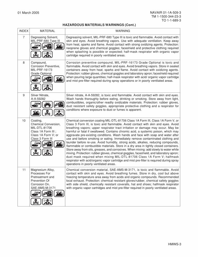
7 ,tnevloSgnisaergeDIIIepyT086-FRP-LIM
htiwtcatnocdiovA.elbammalfdnacixotsiIIIepyT086-FRP-LIM,tnevlosgnisaergeDyawapeeK.noitalitnevetauqedahtiwesU.sropavgnihtaerbdiovA.seyednaniks:noitcetorP.stnegagnizidixognortshtiwtcatnocdiovA.emalfdnaskraps,taehmorf
deriuqergnihtolcevitcetorpdnadleihsecaf;selggoglacimehcdnasevolgenerpoenropavcinagrohtiwrotaripserksam-flah;detcepxeroelbissopsignihsalpsnehw
.saeradetalitnevylroopnideriuqeregdirtrac
8 ,dnuopmoC,evitneverPnoisorroC
37161-FRP-LIMlanoitpOedarG
dnacixotsilanoitpOedarG37161-FRP-LIM,dnuopmocevitneverpnoisorroCdelaesnierotS.sropavgnihtaerbdiovA.seyednanikshtiwtcatnocdiovA.elbammalf.stnegagnizidixohtiwtcatnocdiovA.emalfdnaskraps,taehmorfyawasreniatnoc
deriuqerdleihsecaf;norpayrotarobaldnaselggoglacimehc,sevolgrebbur:noitcetorPegdirtracropavcinagro/dicahtiwrotaripserksam-flah;seititnauqegralgniruopnehw
.saeradetalitnevylroopnirosnoitarepoyarpsgnirudderiuqerretlif-erptsimdna
9 ,etartiNrevliS28295-A-A
.seyednanikshtiwtcatnocdiovA.elbammalfdnacixotsi,28295-A-A,etartinrevliS,thgilmorfyawaerotS.gnikomsrogniknird,gnitaeerofebylhguorohtsdnahhsaW,sevolgrebbur:noitcetorP.slairetamelbazidixoylidaerrehto/cinagro,selbitsubmocrofrotaripseradnagnihtolcevitcetorpetairporppa,selggogytefastnatsisertsud
.tnerappasisemufrotsudoterusopxeerehwsnoitidnoc
01 ,gnitaoC,noisrevnoClacimehC
60718-LTD-LIM;IIImroFA1ssalC
ro;VmroFA1ssalCIIImroF3ssalC
ro,VmroFA1ssalC,IIImroFA1ssalC60718-LTD-LIMgnitaocnoisrevnoclacimehCdiovA.seyednanikshtiwtcatnocdiovA.elbammalfdnacixotsi,IIImroF3ssalCebyaM.ruccoyamegamadronoitatirritcartrotaripserreppu;sropavgnihtaerbyamhcihw,nosiopcimetsysa,dicacimorhcsniatnoC.dewollawsfilatafrolufmrahretfaretawdnapaoshtiwecafdnasdnahhsaW.snoitidnocgnitsixe-erpetavarggadnagnihtolcdetanimatnocevomeryletaidemmI.gnitaerognikomserofebdnaesu,sdnuopmocgnicuder,seilakla,sdicagnorts,ytidimuhdiovA.esu-ererofebrednual.sreniatnocdesolcylthgitniaerayrdanierotS.slairetamelbitsubmocroelbammalf
elihwretawotylwolsdda:gniximnehW.sevisorrocdna,sesaerg,sliomorfyawaerotS;norpayrotarobaldna,dleihsecaf,selggoglacimehc,sevolgrebbur:noitcetorP.gniximksamflah;VmroFA1ssalC60718-LTD-LIMgniximnehwderiuqerksamtsudyarpsgnirudderiuqersiretlif-erptsimdnaegdirtracropavcinagro/dicahtiwrotaripser
.saeradetalitnevylroopnisnoitarepo
11 ,yollAmuisengaMroFsessecorP
dnatnemtaerterPfOnoitneverP,nOnoisorroC
1713-M-SMA-EAS
diovA.elbammalfdnacixotsi,1713-M-SMA-EAS,lairetamnoisrevnoclacimehCevobatublooc,yrdnierotS.semufgnihtaerbdiovA.seyednanikshtiwtcatnocdednemmoceR.sdnuopmoccinagrodnasdicamorfyawaaeraerutarepmetgnizeerfselggogytefaslacimehc,rebbur/sevolgtnatsiserlacimehc:noitcetorP.tsuahxelacolrotaripserksamflah;seohsdnatah,sllarevoctnatsiseryllacimehc,dleihsedishtiw
.saeradetalitnevylroopnideriuqerretlif-erptsimdnasegdirtracropavcinagrohtiw

HMWS-4
NAVAIR 01-1A-509-3TM 1-1500-344-23-3TO 1-1-689-3
01 March 2005
HAZARDOUS MATERIALS WARNINGS (Cont.)
XEDNI LAIRETAM GNINRAW
21 ,citahpilAgnitaoC,enahteruyloP
tnegAlacimehC,tnatsiseR
86164-C-LIM
dnacixotsi,86164-C-LIM,tnatsisertnegalacimehc,gnitaocenahteruylopcitahpilAgnirotsdiovA.sropavgnihtaerbdiovA.seyednanikshtiwtcatnocdiovA.elbammalf:noitcetorP.aeradetalitnev-llewnierotS.secruosnoitingiroerutarepmethgihraendnaeveelsgnolfoesu(gnihtolcevitcetorP.dleihsecaf,selggog,sdraugedis/hsalpsdeilppusriahserfrogniyfirupriarofnoitcetorprotaripserdna)gnihtolcgelgnol
.tnemnorivneropavcinagrorofrotaripser
31 ,sgnitaoCremirP,enrobretaWyxopE
28558-FRP-LIMtpOssalCII/IepyT
cixotsi,lanoitpossalCII/IepyT28558-FRP-LIMgnitaocremirpyxopeenrobretaWerofebsdnahhsaW.sropavfognihtaerbdetaeperrodegnolorpdiovA.elbammalfdnapeeK.esu-ererofebgnihtolcdetanimatnochsaW.moorhsawgnisurognikoms,gnitae-ecaflluf:noitcetorP.saeradetalitnevniylnoerotS.emalfdnaskraps,taehmorfyawa,selggoglacimehc,sevolgenerpoen,rotaripserriadeilppuswolf-suounitnoceceipgniyarpsgnirudderiuqergnihtolcevitcetorp;dnuopmocniksevitcetorpdnadleihsecaf
.snoitarepo
41 ,yxopE,gnitaoC,sdiloShgiH
05722-FRP-LIM
diovA.elbammalfdnacixotsi,05722-FRP-LIM,gnitaocyxopetnailpmoc-COVeyeerevessecudorp;seyehtiwtcatnocdiovA.tcatnocniksdetaeperrodegnolorp.emalfdnaskraps,taehmorfyawapeeK.noitalitnevetauqedahtiwesU.noitatirrihtiwserutximevisolpxemrofyamsropaV.stnegagnizidixognortshtiwtcatnocdiovAniksevitcetorpdnadleihsecaf,selggoglacimehc,sevolgenerpoen:noitcetorP.riaegdirtracropavcinagrohtiwrotaripserksam-flahdnagnihtolcevitcetorp;dnuopmoceceip-ecaflluf;snoitarepoyarpsgnirudderiuqereraretlif-erptsimtniapdna
.saeradetalitnevylroopnideriuqerrotaripserriadeilppuswolf-suounitnoc
51 ,sgnitaoCremirPdnAlacimehC,yxopE
,tnatsiseRtnevloS77332-FRP-LIM
tpOssalCII/IepyT
,II/IepyT,77332-FRP-LIM,sgnitaocremirpyxopetnatsisertnevlosdnalacimehCfognihtaerbdetaeperrodegnolorptneverP.elbammalfdnacixotsi,lanoitpossalC.seyednanikshtiwtcatnocdiovA.noitcaercigrellaesuacyaM.tsimyarpsrosropav
gnihtolcdetanimatnocrednuaL.aeradetalitnevllew,yrd,loocanidesolcylthgiterotS,rotaripserriadeilppuswolf-suounitnoceceip-ecaflluf:noitcetorP.esuererofeb;dnuopmocniksevitcetorpdnadleihsecaf,selggoglacimehc,sevolgenerpoen
.snoitarepogniyarpsgnirudderiuqergnihtolcevitcetorp
61 ,gnitaoCpuhcuoTtfarcriA
)57871etihW(25318-FRP-LIM
htiwtcatnocdiovA.elbammalfdnacixotsi,25318-FRP-LIM,puhcuottfarcriA,gnitaoCnepo,skrapstaeh,stnegagnizidixodiovA.sropavgnihtaerbdiovA.seyednaniksyvaeh:noitcetorP.aeradetnev,yrd,loocnierotS.sdiuqiltohhtiwtcatnocdnasemalfevitcetorptnatsiser,selggogdleihs/edissessalgytefas,sevolgenerpoenytud
.stimilerusopxetnerrucwoleberusopxepeekotaeraetalitneV.tnemrag
71 ,gnitaoC,puhcuoTtfarcriA
)83073kcalB(25318-FRP-LIM
htiwtcatnocdiovA.elbammalfdnacixotsi,25318-FRP-LIM,puhcuottfarcriA,gnitaoCnepo,skraps,taeh,stnegagnizidixodiovA.sropavgnihtaerbdiovA.seyednaniksyvaeh:noitcetorP.aeradetnev,yrd,loocnierotS.sdiuqiltohhtiwtcatnocdnasemalfevitcetorptnatsiser,selggogdleihs/edis,sessalgytefas,sevolgenerpoenytud
.stimilerusopxetnerrucwoleberusopxepeekotaeraetalitneV.tnemrag
HMWS-5
NAVAIR 01-1A-509-3TM 1-1500-344-23-3
TO 1-1-689-3
01 March 2005
HAZARDOUS MATERIALS WARNINGS (Cont.)
XEDNI LAIRETAM GNINRAW
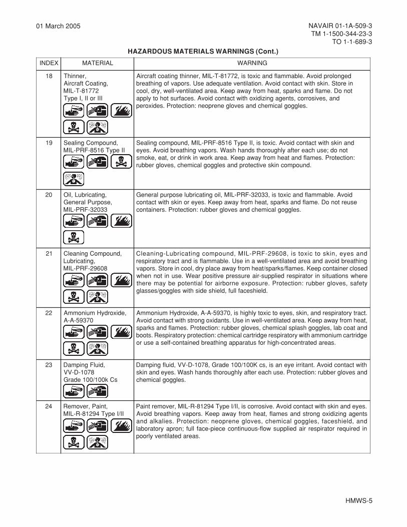
81 ,rennihT,gnitaoCtfarcriA
27718-T-LIMIIIroII,IepyT
degnolorpdiovA.elbammalfdnacixotsi,27718-T-LIM,rennihtgnitaoctfarcriAnierotS.nikshtiwtcatnocdiovA.noitalitnevetauqedaesU.sropavfognihtaerbtonoD.emalfdnaskraps,taehmorfyawapeeK.aeradetalitnev-llew,yrd,looc
dna,sevisorroc,stnegagnizidixohtiwtcatnocdiovA.secafrustohotylppa.selggoglacimehcdnasevolgenerpoen:noitcetorP.sedixorep
91 ,dnuopmoCgnilaeSIIepyT6158-FRP-LIM
dnanikshtiwtcatnocdiovA.cixotsi,IIepyT6158-FRP-LIM,dnuopmocgnilaeStonod;esuhcaeretfaylhguorohtsdnahhsaW.sropavgnihtaerbdiovA.seye
:noitcetorP.semalfdnataehmorfyawapeeK.aerakrowniknirdro,tae,ekoms.dnuopmocniksevitcetorpdnaselggoglacimehc,sevolgrebbur
02 ,gnitacirbuL,liO,esopruPlareneG
33023-FRP-LIM
diovA.elbammalfdnacixotsi,33023-FRP-LIM,liognitacirbulesopruplareneGesuertonoD.emalfdnaskraps,taehmorfyawapeeK.seyeronikshtiwtcatnoc
.selggoglacimehcdnasevolgrebbur:noitcetorP.sreniatnoc
12 ,dnuopmoCgninaelC,gnitacirbuL
80692-FRP-LIM
dnaseye,niksotcixotsi,80692-FRP-LIM,dnuopmocgnitacirbuL-gninaelCgnihtaerbdiovadnaaeradetalitnev-llewaniesU.elbammalfsidnatcartyrotaripserdesolcreniatnocpeeK.semalf/skraps/taehmorfyawaecalpyrd,loocnierotS.sropaverehwsnoitautisnirotaripserdeilppus-riaerusserpevitisopraeW.esunitonnehwytefas,sevolgrebbur:noitcetorP.erusopxeenrobriaroflaitnetopebyamereht
.dleihsecaflluf,dleihsedishtiwselggog/sessalg
22 ,edixordyHmuinommA07395-A-A
.tcartyrotaripserdna,niks,seyeotcixotylhgihsi,07395-A-A,edixordyHmuinommA,taehmorfyawapeeK.aeradetalitnev-llewniesU.stnadixognortshtiwtcatnocdiovA
dnataocbal,selggoghsalpslacimehc,sevolgrebbur:noitcetorP.semalfdnaskrapsegdirtracmuinommahtiwyrotaripseregdirtraclacimehc:noitcetorpyrotaripseR.stoob
.saeradetartnecnoc-hgihrofsutarappagnihtaerbdeniatnoc-flesaesuro
32 ,diulFgnipmaD8701-D-VV
sCk001/001edarG
htiwtcatnocdiovA.tnatirrieyenasi,scK001/001edarG,8701-D-VV,diulfgnipmaDdnasevolgrebbur:noitcetorP.esuhcaeretfaylhguorohtsdnahhsaW.seyednaniks
.selggoglacimehc
42 ,tniaP,revomeRII/IepyT49218-R-LIM
.seyednanikshtiwtcatnocdiovA.evisorrocsi,II/IepyT49218-R-LIM,revomertniaPstnegagnizidixognortsdnasemalf,taehmorfyawapeeK.sropavgnihtaerbdiovAdna,dleihsecaf,selggoglacimehc,sevolgenerpoen:noitcetorP.seilakladnanideriuqerrotaripserriadeilppuswolf-suounitnoceceip-ecaflluf;norpayrotarobal
.saeradetalitnevylroop

HMWS-6
NAVAIR 01-1A-509-3TM 1-1500-344-23-3TO 1-1-689-3
01 March 2005
HAZARDOUS MATERIALS WARNINGS (Cont.)
XEDNI LAIRETAM GNINRAW
52 edixordyHmuidoS -llewaniesU.seyednanikshtiwtcatnocdiovA.cixotsiedixordyHmuidoSdnasevolgenerpoen:noitcetorP.ropavgnihtaerbdiovadnaaeradetalitnev
signihsalpsnehwderiuqergnihtolcevitcetorpdnadleihsecaf;selggoglacimehc.elbissop
62 ,dnuopmoCevitneverPnoisorroC
45058-LTD-LIM
adna,elbammalf,cixotsi,45058-LTD-LIM,dnuopmoCevitneverPnoisorroC.seyednanikshtiwtcatnocdiovA.tnatirritcartyrotaripser TONOD neporaenesu
.ropavgnihtaerbdiovadnasaeradetalitnev-llewniylnoesU.taehro,skraps,emalfylthgitreniatnocpeeK.esuretfaretawdnapaoshtiwylhguorohtsdnahhsaW
fI.selggoglacimehcdnasevolgrebburraew:noitcetorP.esunitonnehwdesolcsetunim51rofretawfostnuomaegralhtiwyletaidemmihsulf,sruccotcatnoceye
,retawdnapaoshtiwhsaw,sruccotcatnocniksfI.noitnettalacidemkeesdnakees,gnitimovecudnitonod,detsegnifI.seohsdnagnihtolcdetanimatnocevomer
.riahserfotaeramorfevomer,srucconoitalahnifI.noitnettalacidem

1-1
NAVAIR 01-1A-509-3TM 1-1500-344-23-3
TO 1-1-689-3
01 March 2005
CHAPTER 1INTRODUCTION
1-1. GENERAL.
1-1.1. Today’s military avionic systems assume asignificant share of the responsibility for missioncompletion, performance capability, and overall systemsafety. The role of avionics includes mission essentialequipment, flight critical equipment, and aircrafthardware. For example, navigation, communications,electronic warfare, weapon management, flight/enginecontrols and displays, and wiring are all consideredavionics. Electronics and electrical power systems arealso considered avionics. The reliability of these complexsystems in any environment is critical for aircraft flightand mission essential functions.
NOTE
In this manual, use of the term "avionic systems"shall refer to any device that uses electricalpower. The term “avionic technician” shallinclude the aviation electrician, aviationelectronic technician, or any personnelauthorized to perform maintenance on avionicsystems.
1-1.2. Corrosion is a major cause of avionicequipment failures, particularly while installed in militaryaircraft. In many cases, even minute amounts ofcorrosion can cause intermittent malfunction orcomplete failure of the equipment. Past experienceshows that in order to obtain certain electricalcharacteristics, for example, low electromagneticinterference (EMI), a compromise in the designselection of materials might be needed (for example,the use of conductive adhesive). Sometimes suchcompromises can lead to corrosion problems that areaggravated by exposure to varying environmentalconditions (for example, EMI corrosion). Avionicequipment is routinely exposed to varyingenvironmental conditions. These conditions includechanging temperatures and pressures, varyinghumidity, dust, dirt, and industrial pollutants in theatmosphere that often initiate corrosion.
1-1.3. The types of corrosion that occur on avionicequipment are similar to those found on airframestructures. The difference between avionic and airframecorrosion is that small amounts of corrosion in avionicequipment can cause intermittent malfunction orcomplete failure, while it may not impact airframestructures.
1-2. PURPOSE. The purpose of this manual is toprovide information on materials and procedures toprevent, control, and repair corrosion damage to avionicson land or at sea.
1-3. SCOPE. The material in this manual containsbasic avionic corrosion prevention and correctivemaintenance information to be used at theOrganizational/Unit and Intermediate levels.
1-4. ARRANGEMENT OF MANUAL.
1-4-1. A complete set of manuals to perform avionicsand electronics cleaning and corrosion control functionsconsists of Volumes I, III, and IV (Navy and Army) orVolumes I, III, and V (Air Force).
1-4.2 Arrangement of Volume III. Volume III consistsof ten chapters, arranged as shown in Table 1-1.
1-5. RELATED PUBLICATIONS. Tables 1-2(Navy), 1-3 (Air Force), 1-4 (Army), and 1-5 (Other) listtechnical publications that may be used assupplemental references by personnel involved incleaning and corrosion control.
1-6. CONSUMABLES AND EQUIPMENT.Procurement information for ordering consumables andequipment referenced in this volume may be found inVolume IV (Navy and Army) or Volume V (Air Force) ofthis manual.
This volume was prepared under the technical cognizance of theChemistry and Materials Division, NAVAIR China Lake, China Lake, California.

1-2
NAVAIR 01-1A-509-3TM 1-1500-344-23-3TO 1-1-689-3
01 March 2005
Table 1-1. Outline of Volume III
RETPAHC ELTIT NOITPIRCSEDFEIRB
1 noitcudortnI .emulovsihtfotuoyaldnaepocsehtstneserpretpahcsihT
2 dnagninaelCnoitacirbuL
cinoivaehttsissaotseuqinhcetdnatnempiuqe,slairetamehtsebircsedretpahcsihTehttatnempiuqecinoivafonoitacirbuldnagninaelclacinahcemehtninaicinhcet
.slevelecnanetniametaidemretnIdnatinU/lanoitazinagrO
3 dnanoitcepsnIenorPnoisorroC
saerA
tsomstnenopmocehtstsildna,noisorrocezingocerotwohsnialpxeretpahcsihT.noisorrocybdetceffa
4 lavomeRnoisorroC .egamadnoisorrocfolavomerehtrofsdohtemdevorppaehtseniltuoretpahcsihT
5 tnemtaerTecafruS ehtdna,stnalaesfonoitacilppaehtrofsdohtemdehsilbatseehtseniltuoretpahcsihTlanretxesuoiravotdeilppaebnactahtsgnitaocdnastnemtaertfonoitacilpparalucitrap
fonoitacilpparalucitrapehtsebircsedretpahcsihT.tnempiuqecinoivalanretnidnacinoivalanretnidnalanretxesuoiravotdeilppaebnactahtsgnitaocdnastnemtaert
.tnempiuqe
6 fotnemtaerTsaerAcificepS
morfnoisorrocgnivomerrofseuqinhcetdnaslairetamehtsebircsedretpahcsihTotseuqinhcetdnaerawdrahtsebehtsebircseddna,tnempiuqecinoivafosepytsuoirav
.snoitcennocgnidnuorgrognidnobgnitsixegnicalperrogniriapernehwdesueb
7 citengamortcelE)IME(ecnerefretnI
gnidleihS
scinoivayratilimhcihwnitnemnorivnecitengamortceleehtsebircsedretpahcsihTeziminimotdesuseuqinhcetdnaserusaemnoitcetorpsweivertI.etarepo
.ecnerefretnicitengamortcele
8 citatsortcelE)DSE(egrahcsiD
dna,egrahcsidcitatsortcelegnidnuorrusyroehtcisabehtsebircsedretpahcsihT.gnirruccomorfDSEpeekotelbaliavayltnerrucsdohtememosseniltuo
9 dnanoitavreserPgnigakcaP
cinoivaehttsissaotseuqinhcetdnatnempiuqe,slairetamehtsebircsedretpahcsihTehttatnempiuqecinoivafognigakcapdnanoitavreserpehtninaicinhcet
.slevelecnanetniametaidemretnIdnatinU/lanoitazinagrO
01 ycnegremEserudecorP
sahtnempiuqecinoivaretfadewollofebotserudecorpycnegremeseniltuoretpahcsihT.stnegagnihsiugnitxeerifro,noisremmiretaw,retawtlasotdesopxeneeb
xednIlacitebahplA .launaMehtnistcejbuscificepssetacolxednisihT

1-3
NAVAIR 01-1A-509-3TM 1-1500-344-23-3
TO 1-1-689-3
01 March 2005
Table 1-2. Related Navy Publications
REBMUN ELTIT
41-R08-00AN launaMeucseRdnagnithgiferiFtfarcriAyvaN.S.USPOTAN
1-A1-10AN riapeRtfarcriArofkoobdnaHgnireenignEdnalaunaMlareneG,riapeRlarutcurtS
8-A1-10AN erawdraHlarutcurtSriapeRelissiMdnatfarcriAseireSlaunaMgnireenignE
61-A1-10AN launaMlacinhceTsdohteMnoitcepsnIevitcurtsednoN
71-A1-10AN sleveLtopeD/etaidemretnI/lanoitazinagrO,launaMsciluardyHnoitaivA
22-A1-10AN ecnanetniaMtopeDdnaetaidemretnI,lanoitazinagrO,tfarcriA,srevoCannetnAdnasemodaR
32-A1-10AN ,riapeRylbmessAcinortcelE)M2(ezirutainimorcim/erutainiMrofsecitcarPecnanetniaMdradnatSleveLetaidemretnI/lanoitazinagrO
53-A1-10AN ecnanetniaMtopeDdna,etaidemretnI,lanoitazinagrO,sknaTlanretxE/lanretnIdnaslleCleuFtfarcriAsnoitcurtsnI
505-A1-10AN gniriWcinortcelEdnacirtcelEtfarcriArofsecitcarPnoitallatsnI
705-A1-10AN launaMlacinhceT,foesUlareneG,sgnitaoCdna,stnalaeS,stnemeC
025-A1-10AN tfarcriAdekraPfognitsorfeDdnagnici-eD,gnici-itnA
5.6-1-31AN roflaunaM,metsySwerCnoitaivA,tnempiuqElavivruSdnaeucseR
4-10-51AN tfarcriAroflaunaMssecorPdnanoitavreserPegarotStreseD
005-10-51AN ecnanetniaMtopeDdnaetaidemretnI,lanoitazinagrO,tfarcriAlavaNfonoitavreserP
521-1-71AN ,snoitcurtsnIecnanetniaM,lortnoCnoisorroCdna,noitavreserP,gninaelCtnempiuqEtroppuSsleveLetaidemretnIdnalanoitazinagrO
1-DAB51-71AN tfarcriAecroFriAdnayvaNnwodkaerBstraPdetartsullIhtiWsnoitcurtsnIecnanetniaMdnanoitarepOseirettaBegarotStnempiuqEtroppuStfarcriAdna
1-MB5-71AN elbatroPnwodkaerBstraPdetartsullIhtiWsnoitcurtsnIluahrevOdna,ecivreS,noitarepOkoobdnaH4140-D-27-00600N)TSALB-UCAV(30314.oNtraPenihcaMgninoHyrD
3-MB5-71AN gninoHnwodkaerBstraPdetartsullIhtiWecnanetniaMtopeDdnaetaidemretnI,lanoitazinagrO6360-C-27-38300NYNAPMOCGNIRUTCAFUNAMOREZ7-051-CDNA6-051-CenihcaM
1-6-22-006-71AN tsilkcehClanoitarepoerPelbatroP,)tsalB-ucaV/oreZ(enihcaMgninoHyrD
2-6-22-006-71AN stnemeriuqeRecnanetniaMcidoirePelbatroP,)tsalB-ucaV/oreZ(enihcaMgninoHyrD
1-D02-91AN traC.nwodkaerBstraPdetartsullIhtiwsnoitcurtsnIecivreSlanoitarepO,lortnoCnoisorroCenignEteJ1-1J-201A56.oNtraP
2-D02-91AN .oNtraPecnanetniaMetaidemretnIdnanoitarepO,detnuoMreliarT,lortnoCnoisorroC,tinUyarpSA03-00040E67
805-E52-91AN tfarcriAnwodkaerBstraPdetartsullIhtiWsnoitcurtsnIecnanetniaMetaidemretnIdnanoitarepOD-04DrebmuNtraP61-M23S/AdetnuoMkcurT,recieD
000-FAS-HSOAN-1AAN tnemhsilbatsEerohSehtrofstnemeriuqeRHSORIAVAN
08-PCAFVAN airetirCrotcaFgninnalPytilicaF,snoitallatsnIerohSsproCeniraM&yvaN
272-PCAFVAN rofngiseDevitinifeD,seitilicaFerohSlavaN
-HSRIL5014PUSVAN gnildnaHlaicepSgniriuqeRsmetIfotsiL
2.0974TSNIVANPO )PMAN(margorPecnanetniaMnoitaivAlavaN
32.0015TSNIVANPO margorP)HSOVAN(htlaeHdnaytefaSlanoitapuccOyvaN

1-4
NAVAIR 01-1A-509-3TM 1-1500-344-23-3TO 1-1-689-3
01 March 2005
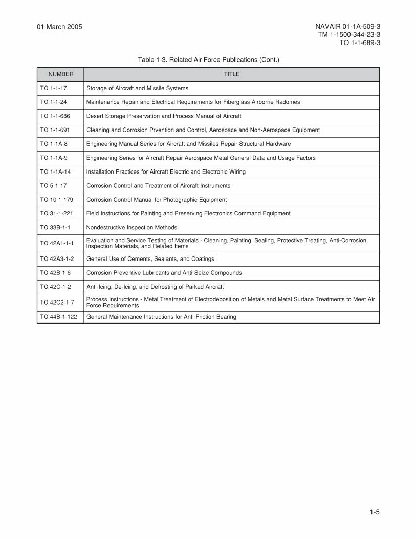
Table 1-3. Related Air Force Publications
REBMUN ELTIT
2407-23IFA ecnailpmoCetsaWsuodrazaHdnadiloS
66-19HSOFA snoitarepOlairtsudnIlareneG
731-84HSOFA margorPnoitcetorPyrotaripseR
41-58PFA ediuGtnemevorpmIytilicaFsrednammoC
7601-23IFA smetsySretaW
501-12IFA ecnanetniaMlarutcurtStnempiuqEecapSdnariA
1-5-00OT metsySredrOlacinhceTFA
1-02-00OT serudecorPdna,seiciloP,noitatnemucoD,noitcepsnIecnanetniaMtnempiuqEecapsoreA
2-02-00OT noitatnemucoDataDecnanetniaMehT
701-52-00OT ecnatsissAecnanetniaM
680D metsyStnemngissAdaolkroWnoissiM
271-52-00OT gnidnoB/gnidnuorGcitatSdnatfarcriAfognicivreSdnuorG
302-52-00OT ecroFriASU,seitilicaFecapsoreAfolortnoCnoitanimatnoC
432-52-00OT tnempiuqElacirtcelEfotseTdna,ecnanetniaM,riapeRehtrofstnemeriuqeRecitcarPpohSlareneG
45-D53-00OT secivreSgnitagitsevnIdnagnitropeRycneicifeDlairetaMFASU
3-58-00OT lareneG-gnikcaPnoitavreserPdnagnigakcaPevitcetorP
1-A011-00OT )tuollaF(sirbeDevitcaoidaRdnadetanimatnoClairetaMdnatfarcriAfognildnaHdnanoitacifitnedIrofsenilediuG
3-1-1OT slleCleuFdna,sknaTlargetnItfarcriAforiapeRdnanoitcepsnI
8-1-1OT tnempiuqEecapsoreA-noNdnaecapsoreA,sgnitaoCcinagrOfolavomeRdnanoitacilppA
1-5
NAVAIR 01-1A-509-3TM 1-1500-344-23-3
TO 1-1-689-3
01 March 2005
REBMUN ELTIT
71-1-1OT smetsySelissiMdnatfarcriAfoegarotS
42-1-1OT semodaRenrobriAssalgrebiFrofstnemeriuqeRlacirtcelEdnariapeRecnanetniaM
686-1-1OT tfarcriAfolaunaMssecorPdnanoitavreserPegarotStreseD
196-1-1OT tnempiuqEecapsoreA-noNdnaecapsoreA,lortnoCdnanoitnevrPnoisorroCdnagninaelC
8-A1-1OT erawdraHlarutcurtSriapeRselissiMdnatfarcriArofseireSlaunaMgnireenignE
9-A1-1OT srotcaFegasUdnaataDlareneGlateMecapsoreAriapeRtfarcriArofseireSgnireenignE
41-A1-1OT gniriWcinortcelEdnacirtcelEtfarcriArofsecitcarPnoitallatsnI
71-1-5OT stnemurtsnItfarcriAfotnemtaerTdnalortnoCnoisorroC
971-1-01OT tnempiuqEcihpargotohProflaunaMlortnoCnoisorroC
122-1-13OT tnempiuqEdnammoCscinortcelEgnivreserPdnagnitniaProfsnoitcurtsnIdleiF
1-1-B33OT sdohteMnoitcepsnIevitcurtsednoN
1-1-1A24OT ,noisorroC-itnA,gnitaerTevitcetorP,gnilaeS,gnitniaP,gninaelC-slairetaMfognitseTecivreSdnanoitaulavEsmetIdetaleRdna,slairetaMnoitcepsnI
2-1-3A24OT sgnitaoCdna,stnalaeS,stnemeCfoesUlareneG
6-1-B24OT sdnuopmoCezieS-itnAdnastnacirbuLevitneverPnoisorroC
2-1-C24OT tfarcriAdekraPfognitsorfeDdna,gnicI-eD,gnicI-itnA
7-1-2C24OT riAteeMotstnemtaerTecafruSlateMdnaslateMfonoitisopedortcelEfotnemtaerTlateM-snoitcurtsnIssecorPstnemeriuqeRecroF
221-1-B44OT gniraeBnoitcirF-itnArofsnoitcurtsnIecnanetniaMlareneG
Table 1-3. Related Air Force Publications (Cont.)
1-6
NAVAIR 01-1A-509-3TM 1-1500-344-23-3TO 1-1-689-3
01 March 2005
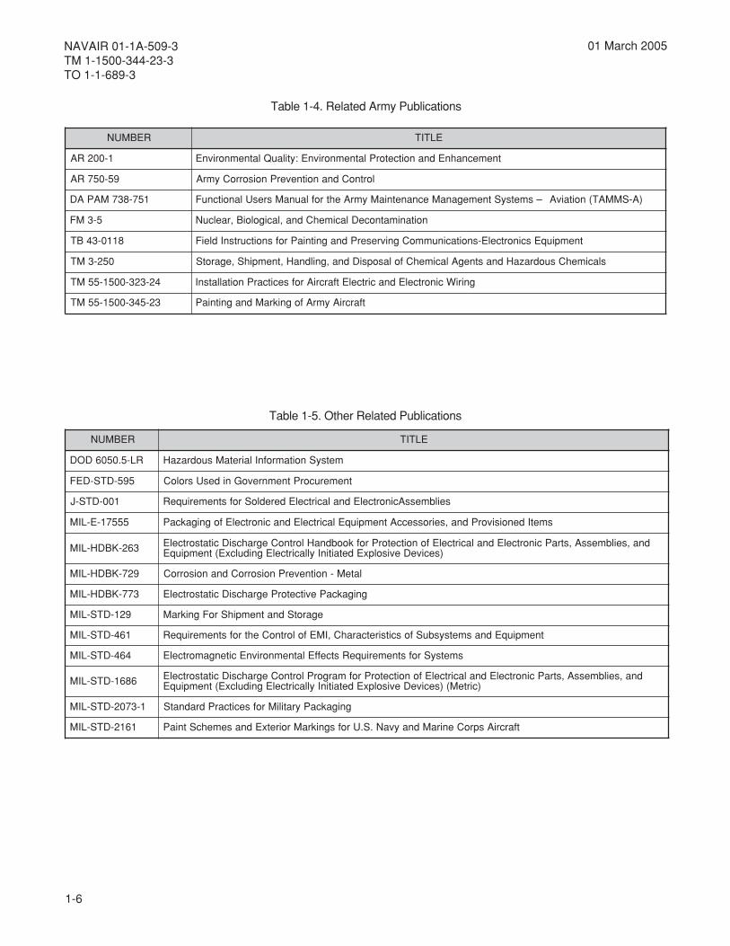
Table 1-4. Related Army Publications
Table 1-5. Other Related Publications
REBMUN ELTIT
1-002RA tnemecnahnEdnanoitcetorPlatnemnorivnE:ytilauQlatnemnorivnE
95-057RA lortnoCdnanoitneverPnoisorroCymrA
157-837MAPAD )A-SMMAT(noitaivA–smetsyStnemeganaMecnanetniaMymrAehtroflaunaMsresUlanoitcnuF
5-3MF noitanimatnoceDlacimehCdna,lacigoloiB,raelcuN
8110-34BT tnempiuqEscinortcelE-snoitacinummoCgnivreserPdnagnitniaProfsnoitcurtsnIdleiF
052-3MT slacimehCsuodrazaHdnastnegAlacimehCfolasopsiDdna,gnildnaH,tnempihS,egarotS
42-323-0051-55MT gniriWcinortcelEdnacirtcelEtfarcriArofsecitcarPnoitallatsnI
32-543-0051-55MT tfarcriAymrAfognikraMdnagnitniaP
REBMUN ELTIT
RL-5.0506DOD metsySnoitamrofnIlairetaMsuodrazaH
595-DTS-DEF tnemerucorPtnemnrevoGnidesUsroloC
100-DTS-J seilbmessAcinortcelEdnalacirtcelEderedloSrofstnemeriuqeR
55571-E-LIM smetIdenoisivorPdna,seirosseccAtnempiuqElacirtcelEdnacinortcelEfognigakcaP
362-KBDH-LIM dna,seilbmessA,straPcinortcelEdnalacirtcelEfonoitcetorProfkoobdnaHlortnoCegrahcsiDcitatsortcelE)seciveDevisolpxEdetaitinIyllacirtcelEgnidulcxE(tnempiuqE
927-KBDH-LIM lateM-noitneverPnoisorroCdnanoisorroC
377-KBDH-LIM gnigakcaPevitcetorPegrahcsiDcitatsortcelE
921-DTS-LIM egarotSdnatnempihSroFgnikraM
164-DTS-LIM tnempiuqEdnasmetsysbuSfoscitsiretcarahC,IMEfolortnoCehtrofstnemeriuqeR
464-DTS-LIM smetsySrofstnemeriuqeRstceffElatnemnorivnEcitengamortcelE
6861-DTS-LIM dna,seilbmessA,straPcinortcelEdnalacirtcelEfonoitcetorProfmargorPlortnoCegrahcsiDcitatsortcelE)cirteM()seciveDevisolpxEdetaitinIyllacirtcelEgnidulcxE(tnempiuqE
1-3702-DTS-LIM gnigakcaPyratiliMrofsecitcarPdradnatS
1612-DTS-LIM tfarcriAsproCeniraMdnayvaN.S.UrofsgnikraMroiretxEdnasemehcStniaP
2-1
NAVAIR 01-1A-509-3TM 1-1500-344-23-3
TO 1-1-689-3
01 March 2005
CHAPTER 2CLEANING AND LUBRICATION
2-1. GENERAL.
2-1.1. The materials, equipment, and techniquesdescribed in this chapter are intended to assist theavionic technician at the Intermediate MaintenanceActivity (IMA). This includes the cleaning and drying ofavionic equipment. Generally, where supportequipment is available, corrosion removal, cleaning,and drying is more efficient.
2-1.2. Gross contamination requires supportequipment capable of cleaning and corrosion removalas specified in the cleaning tracks (paragraph 2-4).The alternate cleaning procedures listed (paragraph2-5) are considered sufficient for "day-to-day" cleaningand when support equipment is not available.
2-1.3. Pending standardization, use only supportequipment that meets the general specifications asoutlined in Volume IV (Navy and Army) or V (AirForce), Chapter 4.
2-1.4. The support equipment that is available in thesupply system is listed in Volume IV (Navy and Army)or V (Air Force), Chapter 3. The general operatingprocedures and limitations for all of the various supportequipment are listed in this chapter.
2-2. AVIONIC CORROSION CLEANING FACILITY.
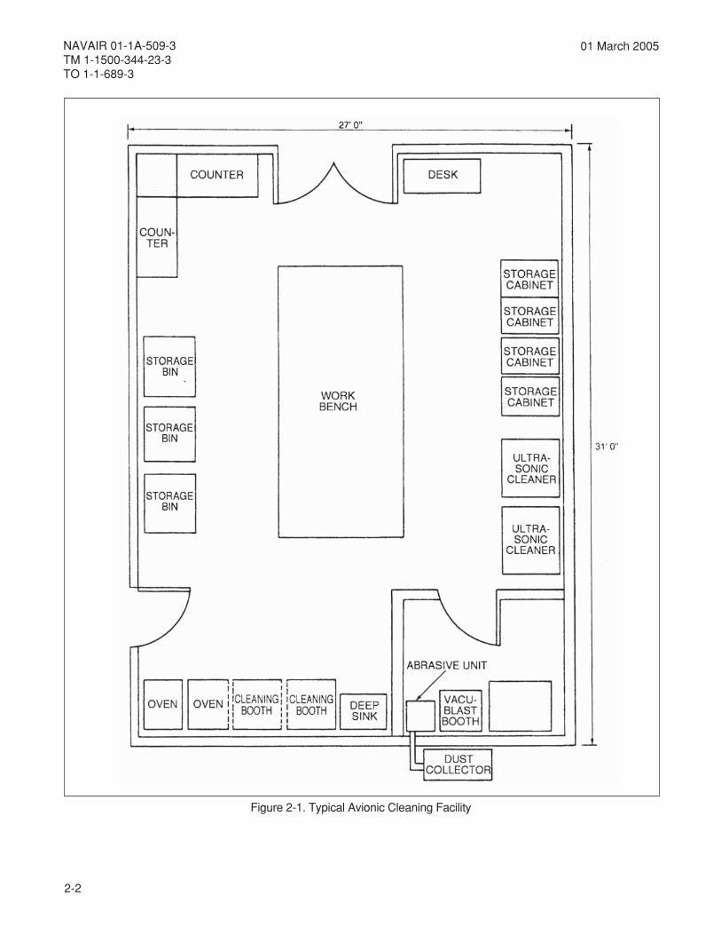
2-2.1. REQUIREMENTS. Where space permits, aseparate avionic corrosion control cleaning facilitycenter shall be established as specified in OPNAVINST4790.2 (Navy) or TO 00-20-1 (Air Force). See Figure 2-1and Figure 2-2 for an example of an avionic cleaningfacility arrangement. The avionic cleaning facility andstaffing shall include the following as a minimum:
CAUTION
Maintenance personnel should be concernedabout safety at all times. Cigarette smoke,food, and beverages can contaminate anddamage avionic equipment. Do not smoke orhave food or beverages in the same workspace as maintenance operations.
a. Adequate space for safe operation of avioniccleaning and corrosion removal equipment.
b. Personnel trained in the operation of each pieceof support equipment.
c. Quality assurance inspectors trained in theoperational characteristics and restrictions of eachpiece of support equipment.
d. Operating instructions for each piece of supportequipment.
e. Safety equipment and clothing as required bylocal directive and this manual.
f. Personnel trained in recognition of corrosion onavionic equipment as specified in this manual.
g. Avionic technicians who can recognize thevarious electrical and electronic components.
2-2.2. ALTERNATE REQUIREMENTS. Supportequipment shall be placed where fumes, overspray,dust, or other residual materials will not contaminateavionic modules or components. The requirementsspecified in paragraph 2-2.1. shall also apply wherevercleaning and corrosion removal equipment is operated.Close supervision and sufficient quality assurancepersonnel/procedures are required at the avioniccleaning facility. Cleaning and corrosion removalequipment can be detrimental to some avioniccomponents. The decision to use cleaning andcorrosion removal equipment shall be the responsibilityof the avionic cleaning facility supervisor.
2-2.3. INDUCTION PROCEDURES. The induction ofavionic equipment for cleaning and/or corrosion controlshall be as follows:
2-2.3.1. Induction of avionic equipment shall bedocumented on the appropriate maintenance actionforms (MAFs) in accordance with proceduresestablished under OPNAVINST 4790.2 (Navy), TO00-20-1 (Air Force), or DA PAM 738-750/DA PAM738.751 (Army).
2-2
NAVAIR 01-1A-509-3TM 1-1500-344-23-3TO 1-1-689-3
01 March 2005
Figure 2-1. Typical Avionic Cleaning Facility
2-3
NAVAIR 01-1A-509-3TM 1-1500-344-23-3
TO 1-1-689-3
01 March 2005
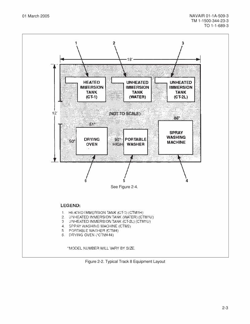
Figure 2-2. Typical Track 8 Equipment Layout
See Figure 2-4.

2-4
NAVAIR 01-1A-509-3TM 1-1500-344-23-3TO 1-1-689-3
01 March 2005
2-2.3.2. Each module or component inducted shall beinspected for:
a. The type of contamination.
b. The extent of corrosion damage.
c. Identification of items considered sensitive tocleaning and corrosion removal procedures.
2-2.3.3. After inspection, the "cleaning track" shall beselected by the criteria provided in paragraph 2-4.
2-3. MATERIALS AND SUPPORT EQUIPMENTREQUIREMENTS.
2-3.1. GENERAL. Avionic technicians mustunderstand the functions, capabilities, and restrictionsthat apply to each material and piece of supportequipment. This prevents damage to personnel andavionic equipment that could result from improper use.
2-3.2. MATERIALS. Consumable materials listed inVolume IV (Navy and Army) or V (Air Force), Chapter 2,and equipment listed in Volume IV (Navy and Army) orV (Air Force), Chapter 3, shall be used for corrosioncontrol. These materials have been approved onlyafter extensive testing to prove their ability to performproperly and effectively. Materials or processesconsidered to be an improvement over existing ones,after local laboratory analysis and evaluation, shall beforwarded to the Aircraft Controlling Custodians (ACC)or System Program Manager (SPM) for submission tothe parent service organization for further evaluation.When approved materials are not available,substitutions shall only be made by the appropriateACC/SPM.
2-3.3. MATERIALS USE. Only those materials listedin this manual shall be used for cleaning or corrosioncontrol of avionic components. Materials listed in othermanuals shall be used only when required proceduresare not covered by this manual. Promising materialstechnology, after local laboratory analysis andevaluation, shall be forwarded to the parent serviceorganization for further evaluation. When severalmethods or materials are listed, the preferred one islisted first, with alternates following.
2-3.4. SUPPORT EQUIPMENT. Tools and supportequipment authorized for cleaning and corrosionremoval on avionics equipment are listed in this chapter,
Chapter 4, and Volume IV (Navy and Army) or V (AirForce) of this manual.
2-3.5. SUPPORT EQUIPMENT USE. Each piece ofsupport equipment has been selected to performspecific functions. These intended functions areidentified in Chapter 4 and include general limitationsapplicable to each type of support equipment.Maintenance personnel should refer to the appropriatesupport equipment operating manuals for specificoperating instructions.
2-4. CLEANING TRACKS.
2-4.1. GENERAL. A cleaning track represents adefinite process that applies to a particular type ofcontaminant or corrosion product. This includesconsideration for the restrictions that may apply to aspecific piece of support equipment and/or avioniccomponent. It is important that cleaning equipmentoperators have a thorough knowledge of electrical andelectronic equipment. This should be supplementedby a knowledge of which components can be processedby a particular cleaning track. These cleaning tracksare shown in Figure 2-3.
2-4.2. CLEANING TRACK SELECTION CRITERIA.The selection of the cleaning track to be used is basedon the following criteria:
NOTE
Always select the mildest form of cleaning thatwill accomplish the task.
a. Type and extent of the contamination orcorrosion.
b. Accessibility to the contamination or corrosion.
c. Type of avionic equipment.
2-4.3. TYPE AND EXTENT OF CONTAMINATION.Table 2-1 describes the various forms of contaminationand the cleaning track best suited for each. There ismore than one track available for cleaning each type ofcontamination. Use hand-cleaning procedures asalternatives if cleaning tracks are not available.
2-4.4. CLEANING TRACK PRESELECTIONREQUIREMENTS. The avionic cleaning facilitysupervisor or equipment operator shall identify the

2-5
NAVAIR 01-1A-509-3TM 1-1500-344-23-3
TO 1-1-689-3
01 March 2005
Figure 2-3. Cleaning Track Diagram
type of contamination and extent of the damage toselect the correct cleaning track. Experience has shownthat most avionic equipment has dirt, dust, or someform of corrosion present, and requires cleaning. Ifcontamination or corrosion is not evident, confirmationvia inspection by an experienced avionic technician isrequired.
2-4.5. ACCESSIBILITY TO CONTAMINATION ANDCORROSION. Visual inspection of avionic componentsusually indicates the extent of contamination and
corrosion damage. Visual inspection also determinesthe cleaning method required to remove contaminantsor corrosion from tight areas. The aqueous ultrasonicand solvent ultrasonic cleaners provide the mostefficient means of cleaning hard to reach areas.Consideration must also be given to drying that followsthe cleaning cycle. In some cases, the most efficientmeans of cleaning may require extensive drying. Thismakes the whole process less efficient.

2-6
NAVAIR 01-1A-509-3TM 1-1500-344-23-3TO 1-1-689-3
01 March 2005
2-4.6. TYPE OF AVIONIC EQUIPMENT. The criteriafor selection of a cleaning track are also based on typeof avionic component to be cleaned. A thoroughinspection of the item to be cleaned is important todetermine the type of circuitry and componentsinvolved. Table 2-2 is a guide for determining thecleaning track to use on various electronic and electricalcomponents.
2-4.7. CLEANING RESTRICTIONS.
2-4.7.1. Selection of the cleaning track is a decision tobe made by the avionic cleaning facility supervisor.Certain circuit components can be damaged by supportequipment.
2-4.7.2. The use of support equipment on certainavionic equipment and components is restricted(paragraphs 2-5.2. to 2-5.2.5.3.).
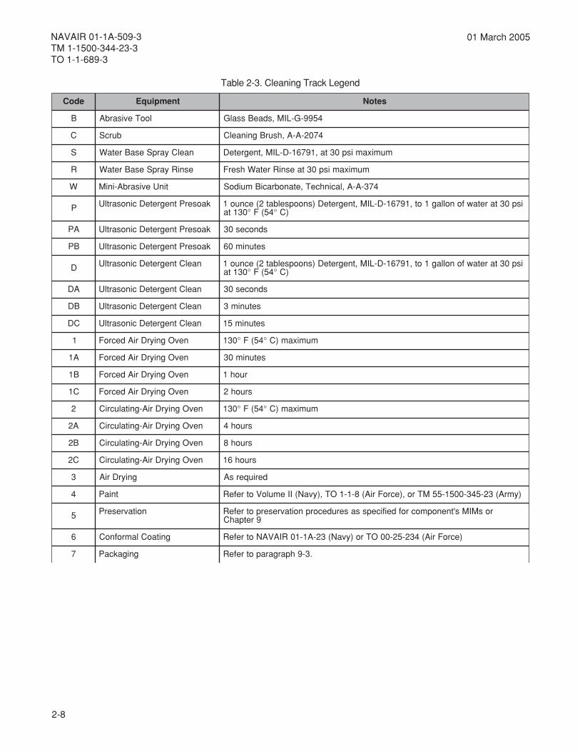
2-4.8. CLEANING TRACK IDENTIFICATION. TheCleaning Track Diagram, Figure 2-3, shall be used inconjunction with Cleaning Track Legend, Table 2-3.The cleaning track legend defines each element of thecleaning track. Each function and subfunction on thecleaning track is assigned an alphanumeric code.These characters are used to identify the cleaningtrack for recordkeeping purposes. It may be desirableto keep a log of all avionic equipment and componentsprocessed through the cleaning tracks. In such cases,the cleaning track number would identify exactly theprocess used when cleaning a particular component.
2-4.9. CLEANING TRACK EXAMPLE. As anillustrative example of cleaning track use, assume thecleaning track is "BCSR235". This would correspondto the following maintenance actions (refer to Figure 2-3and Table 2-3):
a. B - Clean with the abrasive tool and glass beads.
b. C - Scrub with cleaning brush.
c. S - Clean with water base spray with one ounceof detergent, MIL-D-16791, in 1 gallon of fresh water ata maximum of 30 psi.
d. R - Rinse with water base spray with fresh waterat a maximum of 30 psi.
e. 2 - Dry in circulating air drying oven at 130°F(54°C).
f. 3 - Air dry as required.
g. 5 - Preserve as specified by the component’sMaintenance Instruction Manuals (MIMs) or Chapter 9.
2-4.10. CLEANING TRACK DESCRIPTIONS. Thecleaning tracks are designed to fulfill specific functions.Drying selection depends on availability of dryingovens, Volume of the component, and time availablefor drying. Appropriate painting, preservation, andpackaging steps are selected for the individual itembeing cleaned. The following are description of eachcleaning track based on Figure 2-3 and Table 2-3.
2-4.10.1. Track No. 1.
2-4.10.1.1. This track removes light dirt, dust, andsalt spray. Solvent and detergent ultrasonic cleanersare not required. This track is considered the mildestand has the widest application in cleaning of varioustypes of avionic equipment.
2-4.10.1.2. The component is cleaned and rinsed inthe Cleaning Booth (Booth, Cleaning, Water BaseSolvent Spray) using Detergent, MIL-D-16791. Oneounce (2 tablespoons) of detergent is mixed in onegallon of fresh water.
foepyTnoitanimatnoC
srebmuNkcarTgninaelC
1 2 3 4 5 6 7 8
tsuD/triDthgiL
tsuD/triDyvaeH
yarpStlaS
noisorroCthgiL
noisorroCyvaeH
liO
esaerG
diulFciluardyH
Table 2-1. Types of Contamination versusCleaning Tracks

2-7
NAVAIR 01-1A-509-3TM 1-1500-344-23-3
TO 1-1-689-3
01 March 2005
foepyTtnempiuqE
suoeuqAscinosartlU
tnevloSscinosartlU
esaBretaWhtooByarpS looTevisarbA evisarbA-iniM naelCdnaH
edalB,sannetnA
emoD,sannetnA )1( )1( )1(
MCE,sannetnA
radaR,sannetnA )1(
seirettaB
sissahC
rekaerBtiucriCslenaP
laixaoCsrotcennoC
sexoBlortnoC )1(
egdEsrotcennoC
srotareneG )1( )1(
sepocsoryG )1( )1(
ytisneDhgiHsrotcennoC
srevoC/gnisuoH
stnemurtsnI )1(
seilbmessAthgiL )1(
srotoM )1( )1(
dnasgulPsrotcennoC
tiucriCdetnirPsdraoB
stnuoM/skcaR
sorhcnyS/sovreS )1(
sediugevaW )1(
sessenraHeriW
.ylnoesulanretxE)1(:etoN
Table 2-2. Recommended Cleaning Process versus Type of Avionic Equipment
2-8
NAVAIR 01-1A-509-3TM 1-1500-344-23-3TO 1-1-689-3
01 March 2005
edoC tnempiuqE setoN
B looTevisarbA 4599-G-LIM,sdaeBssalG
C burcS 4702-A-A,hsurBgninaelC
S naelCyarpSesaBretaW mumixamisp03ta,19761-D-LIM,tnegreteD
R esniRyarpSesaBretaW mumixamisp03taesniRretaWhserF
W tinUevisarbA-iniM 473-A-A,lacinhceT,etanobraciBmuidoS
P kaoserPtnegreteDcinosartlU isp03taretawfonollag1ot,19761-D-LIM,tnegreteD)snoopselbat2(ecnuo1)C°45(F°031ta
AP kaoserPtnegreteDcinosartlU sdnoces03
BP kaoserPtnegreteDcinosartlU setunim06
D naelCtnegreteDcinosartlU isp03taretawfonollag1ot,19761-D-LIM,tnegreteD)snoopselbat2(ecnuo1)C°45(F°031ta
AD naelCtnegreteDcinosartlU sdnoces03
BD naelCtnegreteDcinosartlU setunim3
CD naelCtnegreteDcinosartlU setunim51
1 nevOgniyrDriAdecroF mumixam)C°45(F°031
A1 nevOgniyrDriAdecroF setunim03
B1 nevOgniyrDriAdecroF ruoh1
C1 nevOgniyrDriAdecroF sruoh2
2 nevOgniyrDriA-gnitalucriC mumixam)C°45(F°031
A2 nevOgniyrDriA-gnitalucriC sruoh4
B2 nevOgniyrDriA-gnitalucriC sruoh8
C2 nevOgniyrDriA-gnitalucriC sruoh61
3 gniyrDriA deriuqersA
4 tniaP )ymrA(32-543-0051-55MTro,)ecroFriA(8-1-1OT,)yvaN(IIemuloVotrefeR
5 noitavreserP rosMIMs'tnenopmocrofdeificepssaserudecorpnoitavreserpotrefeR9retpahC
6 gnitaoClamrofnoC )ecroFriA(432-52-00OTro)yvaN(32-A1-10RIAVANotrefeR
7 gnigakcaP .3-9hpargarapotrefeR
Table 2-3. Cleaning Track Legend
2-9
NAVAIR 01-1A-509-3TM 1-1500-344-23-3
TO 1-1-689-3
01 March 2005
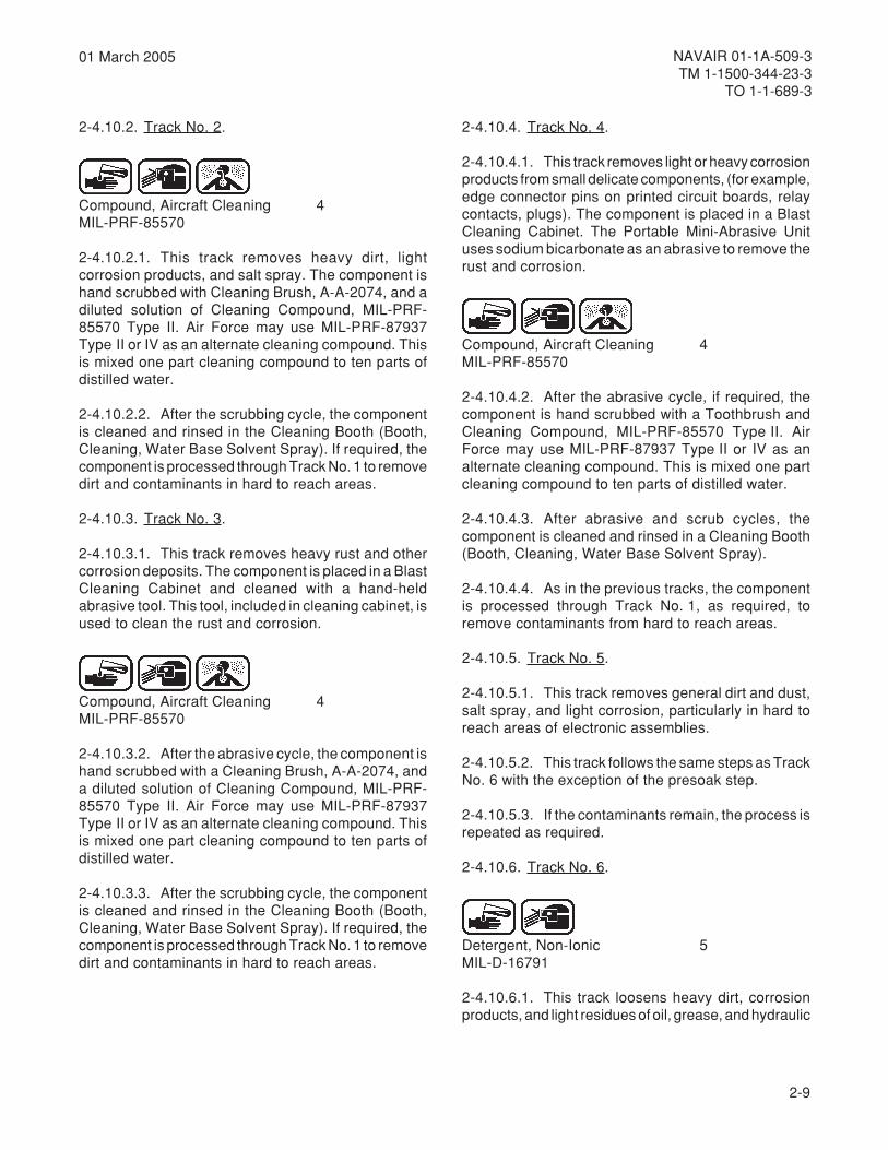
2-4.10.2. Track No. 2.
Compound, Aircraft Cleaning 4MIL-PRF-85570
2-4.10.2.1. This track removes heavy dirt, lightcorrosion products, and salt spray. The component ishand scrubbed with Cleaning Brush, A-A-2074, and adiluted solution of Cleaning Compound, MIL-PRF-85570 Type II. Air Force may use MIL-PRF-87937Type II or IV as an alternate cleaning compound. Thisis mixed one part cleaning compound to ten parts ofdistilled water.
2-4.10.2.2. After the scrubbing cycle, the componentis cleaned and rinsed in the Cleaning Booth (Booth,Cleaning, Water Base Solvent Spray). If required, thecomponent is processed through Track No. 1 to removedirt and contaminants in hard to reach areas.
2-4.10.3. Track No. 3.
2-4.10.3.1. This track removes heavy rust and othercorrosion deposits. The component is placed in a BlastCleaning Cabinet and cleaned with a hand-heldabrasive tool. This tool, included in cleaning cabinet, isused to clean the rust and corrosion.
Compound, Aircraft Cleaning 4MIL-PRF-85570
2-4.10.3.2. After the abrasive cycle, the component ishand scrubbed with a Cleaning Brush, A-A-2074, anda diluted solution of Cleaning Compound, MIL-PRF-85570 Type II. Air Force may use MIL-PRF-87937Type II or IV as an alternate cleaning compound. Thisis mixed one part cleaning compound to ten parts ofdistilled water.
2-4.10.3.3. After the scrubbing cycle, the componentis cleaned and rinsed in the Cleaning Booth (Booth,Cleaning, Water Base Solvent Spray). If required, thecomponent is processed through Track No. 1 to removedirt and contaminants in hard to reach areas.
2-4.10.4. Track No. 4.
2-4.10.4.1. This track removes light or heavy corrosionproducts from small delicate components, (for example,edge connector pins on printed circuit boards, relaycontacts, plugs). The component is placed in a BlastCleaning Cabinet. The Portable Mini-Abrasive Unituses sodium bicarbonate as an abrasive to remove therust and corrosion.
Compound, Aircraft Cleaning 4MIL-PRF-85570
2-4.10.4.2. After the abrasive cycle, if required, thecomponent is hand scrubbed with a Toothbrush andCleaning Compound, MIL-PRF-85570 Type II. AirForce may use MIL-PRF-87937 Type II or IV as analternate cleaning compound. This is mixed one partcleaning compound to ten parts of distilled water.
2-4.10.4.3. After abrasive and scrub cycles, thecomponent is cleaned and rinsed in a Cleaning Booth(Booth, Cleaning, Water Base Solvent Spray).
2-4.10.4.4. As in the previous tracks, the componentis processed through Track No. 1, as required, toremove contaminants from hard to reach areas.
2-4.10.5. Track No. 5.
2-4.10.5.1. This track removes general dirt and dust,salt spray, and light corrosion, particularly in hard toreach areas of electronic assemblies.
2-4.10.5.2. This track follows the same steps as TrackNo. 6 with the exception of the presoak step.
2-4.10.5.3. If the contaminants remain, the process isrepeated as required.
2-4.10.6. Track No. 6.
Detergent, Non-Ionic 5MIL-D-16791
2-4.10.6.1. This track loosens heavy dirt, corrosionproducts, and light residues of oil, grease, and hydraulic
2-10
NAVAIR 01-1A-509-3TM 1-1500-344-23-3TO 1-1-689-3
01 March 2005
fluids. The component is precleaned and rinsed in aCleaning Booth (Booth, Cleaning, Water Base SolventSpray).
2-4.10.6.2. The Aqueous Ultrasonic Cleaner uses acleaning solution of water and Detergent, MIL-D-16791.One ounce (2 tablespoons) of detergent is mixed inone gallon of fresh water at 130°F (54°C).
2-4.10.6.3. The component is suspended in theultrasonic tank solution in a wire basket approximately12 inches below the surface. Presoak for a period of 30to 60 minutes, as appropriate.
2-4.10.6.4. After the presoak cycle, the component iscleaned in the same tank by ultrasonic mode at 20 kHz.The selection of time cycle for ultrasonic mode dependson the amount of contamination.
2-4.10.6.5. The component is rinsed in a CleaningBooth (Booth, Cleaning, Water Base Solvent Spray)after ultrasonic cleaning. If contaminants remain, thecomponent is returned to presoak and the process isrepeated as required.
2-4.10.7. Track No. 7.
2-4.10.7.1. This track removes grease, oil, andhydraulic fluid contamination. The solvent degreasingoperation is performed by the Solvent UltrasonicCleaner. The ultrasonic tanks use cleaning solvent,ENVIROSOLV 654CR.
2-4.10.7.2. The component is placed in the ultrasonicsolvent tank 6 inches above the bottom of the tank tocomplete the cleaning cycle.
2-4.10.7.3. The selection of time cycle for ultrasonicmode depends on the amount of contamination presentand the type of circuitry involved.
2-4.10.7.4. If required, the component is cleaned andrinsed in the Cleaning Booth (Booth, Cleaning, WaterBase Solvent Spray).
2-4.10.8. Track No. 8.
2-4.10.8.1. The referenced cleaning equipment isrepresentative for these procedures. Suitablesubstitutes may be used. Figure 2-2 shows arepresentative cleaning line layout and typical spacerequirements. A typical portable washer (CTM4)(Figure 2-4) is offered in both automatic and manual
models and requires 1 square meter of shop floorspace and a 110 or 220 volt source.
2-4.10.8.2. Although the information presented in thisprocedure is based upon the evaluation of CHEM-TECH International Inc. equipment and associatedprocesses, the Track 8 procedures can be tailored toother commercially available equipment and cleaningagents.
2-4.10.8.3. Cleaning Equipment. Refer to Volume IVor V for the physical characteristics and facilityrequirements for the Track 8 cleaning line of equipment.
2-4.10.8.4. Cleaning Agents.
WARNING
Some cleaning chemicals may be toxic andflammable. Avoid contact with skin and eyes.Avoid breathing vapors. Use with adequateventilation. Keep away from heat, sparks andflame. Avoid contact with strong oxidizingagents. Protection: neoprene gloves andchemical goggles; faceshield and protectiveclothing required when splashing is possibleor expected; half-mask respirator with organicvapor cartridge required in poorly ventilatedareas.
Unless designated otherwise by the cognizantfield activity or manufacturer, spent cleaningmaterials shall be segregated and stored asregulated waste for ultimate off-site dispositionvia licensed contractor.
2-4.10.8.4.1. CT-1 is a water-based multipurposecleaning detergent used to clean electromechanicaland electronic assemblies.
2-4.10.8.4.2. CT-2L is a single step cleaning agent orsupplemental treating agent following CT-1 cleaning.CT-2L is a water displacement agent.
2-4.10.8.5. Avionic Equipment. Caution shall beexercised to ensure there will be no adverse effects onavionic equipment performance as a result of thecleaning process.
2-4.10.8.6. Cleaning Procedures.
2-4.10.8.6.1. Equipment Preparation. A thoroughinspection of the item to be cleaned is important to

2-11
NAVAIR 01-1A-509-3TM 1-1500-344-23-3
TO 1-1-689-3
01 March 2005
ensure that the process and cleaning agents arecompatible with the manufacturer’s recommendations.
2-4.10.8.6.2. Cleaning Agent Preparation. Preparecleaning agent CT-1 with 5 parts deionized water and1 part CT-1. CT-2L is used as supplied.
2-4.10.8.6.3. Cleaning Procedure. There are two batchtype Track 8 cleaning procedures: CT-1/CT-2LCleaning Process and CT-1/CT-2L Cleaning Process(Ultrasonics).
CAUTION
Refer to manufacturer supplied material safetydata sheets (MSDS) for applicable usageprecautions and appropriate personalprotective equipment.
2-4.10.8.6.3.1. CT-1/CT-2L Cleaning Process.
NOTE
Heated water will accelerate the cleaningprocess.
Figure 2-4. Portable Washer (CTM4)
2-12
NAVAIR 01-1A-509-3TM 1-1500-344-23-3TO 1-1-689-3
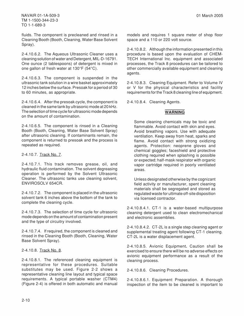
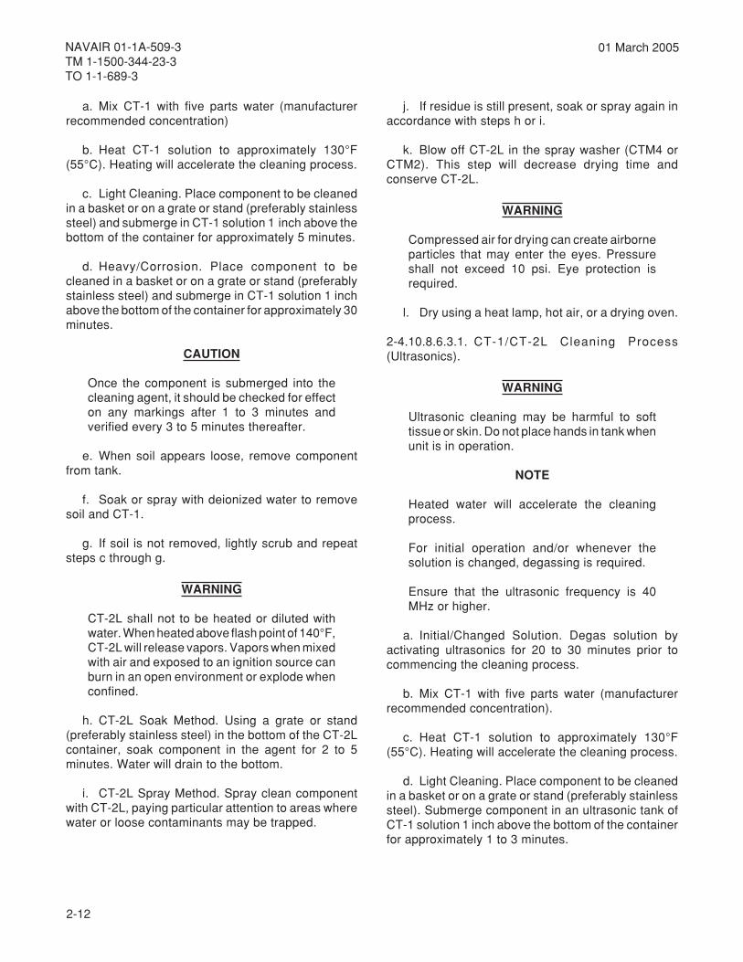
01 March 2005
a. Mix CT-1 with five parts water (manufacturerrecommended concentration)
b. Heat CT-1 solution to approximately 130°F(55°C). Heating will accelerate the cleaning process.
c. Light Cleaning. Place component to be cleanedin a basket or on a grate or stand (preferably stainlesssteel) and submerge in CT-1 solution 1 inch above thebottom of the container for approximately 5 minutes.
d. Heavy/Corrosion. Place component to becleaned in a basket or on a grate or stand (preferablystainless steel) and submerge in CT-1 solution 1 inchabove the bottom of the container for approximately 30minutes.
CAUTION
Once the component is submerged into thecleaning agent, it should be checked for effecton any markings after 1 to 3 minutes andverified every 3 to 5 minutes thereafter.
e. When soil appears loose, remove componentfrom tank.
f. Soak or spray with deionized water to removesoil and CT-1.
g. If soil is not removed, lightly scrub and repeatsteps c through g.
WARNING
CT-2L shall not to be heated or diluted withwater. When heated above flash point of 140°F,CT-2L will release vapors. Vapors when mixedwith air and exposed to an ignition source canburn in an open environment or explode whenconfined.
h. CT-2L Soak Method. Using a grate or stand(preferably stainless steel) in the bottom of the CT-2Lcontainer, soak component in the agent for 2 to 5minutes. Water will drain to the bottom.
i. CT-2L Spray Method. Spray clean componentwith CT-2L, paying particular attention to areas wherewater or loose contaminants may be trapped.
j. If residue is still present, soak or spray again inaccordance with steps h or i.
k. Blow off CT-2L in the spray washer (CTM4 orCTM2). This step will decrease drying time andconserve CT-2L.
WARNING
Compressed air for drying can create airborneparticles that may enter the eyes. Pressureshall not exceed 10 psi. Eye protection isrequired.
l. Dry using a heat lamp, hot air, or a drying oven.
2-4.10.8.6.3.1. CT-1/CT-2L Cleaning Process(Ultrasonics).
WARNING
Ultrasonic cleaning may be harmful to softtissue or skin. Do not place hands in tank whenunit is in operation.
NOTE
Heated water will accelerate the cleaningprocess.
For initial operation and/or whenever thesolution is changed, degassing is required.
Ensure that the ultrasonic frequency is 40MHz or higher.
a. Initial/Changed Solution. Degas solution byactivating ultrasonics for 20 to 30 minutes prior tocommencing the cleaning process.
b. Mix CT-1 with five parts water (manufacturerrecommended concentration).
c. Heat CT-1 solution to approximately 130°F(55°C). Heating will accelerate the cleaning process.
d. Light Cleaning. Place component to be cleanedin a basket or on a grate or stand (preferably stainlesssteel). Submerge component in an ultrasonic tank ofCT-1 solution 1 inch above the bottom of the containerfor approximately 1 to 3 minutes.

2-13
NAVAIR 01-1A-509-3TM 1-1500-344-23-3
TO 1-1-689-3
01 March 2005
e. Heavy Corrosion. Place component to be cleanedin a basket or on a grate or stand (preferably stainlesssteel) and submerge in CT-1 solution 1 inch above thebottom of the container for approximately 10 minutes.
CAUTION
Once the component is submerged into thecleaning agent, it should be checked for effecton any markings after 1 to 3 minutes andverified every 3 to 5 minutes thereafter.
NOTE
If component is not cleaned in 10 minutes,component should be removed and inspectedto determine whether to resoak in the CT-1cleaning agent.
f. Soak or spray with deionized water to removesoil and CT-1.
g. If soil is not removed, lightly scrub and repeatsteps d through g.
WARNING
CT-2L shall not be heated or diluted withwater. When heated above flash point of 140°F,CT-2L will release vapors. Vapors when mixedwith air and exposed to an ignition source canburn in an open environment or explode whenconfined.
h. CT-2L Soak Method. Using a basket, grate, orstand (preferably stainless steel) in the bottom of theCT-2L container, soak component in the agent for 2 to5 minutes. Water will drain to the bottom.
i. CT-2L Spray Method. Spray clean componentwith CT-2L paying particular attention to areas wherewater or loose contaminants may be trapped.
j. If residue is still present, soak or spray inaccordance with step h or i.
k. Blow off CT-2L in the spray washer (CTM4 orCTM2). This step will decrease drying time andconserve CT-2L.
l. Dry using a heat lamp, hot air, or a drying oven.
2-4.10.8.7. Disposal.
2-4.10.8.7.1. CT-1. CT-1 is biodegradable. Disposaldepends on the contaminant being removed and theapplicable state and local regulations. Landfill solids atpermitted sites via licensed contractor in accordancewith applicable federal, state and local regulations.
2-4.10.8.7.2. CT-2L. Landfill solids at permitted sitesvia licensed contractor. Used products may be classifiedas hazardous waste (ignitable) due to low flash pointand may be incinerated or burned for energy recovery.CT-2L has a heating value of 20156 BTU/lb. Eitheroption must be performed in accordance with federal,state and local regulations.
2-5. CLEANING MATERIALS, EQUIPMENT, ANDTECHNIQUES.
2-5.1. AVIONIC CLEANING MATERIALS. Thefollowing paragraphs provide information to ensurethe proper selection and application of avionic cleaningmaterials.
2-5.1.1. Availability of Materials. Only materials,equipment, and techniques approved by the applicableparent service organization shall be used on militaryaircraft and avionic systems. Volume IV and V,Chapter 2 (Consumable Materials), Volume IV and V,Chapter 3 (Equipment for Corrosion Control), andVolume IV and V, Chapter 4 (Special AvionicEquipment) are provided to ensure the availability ofapproved materials and equipment.
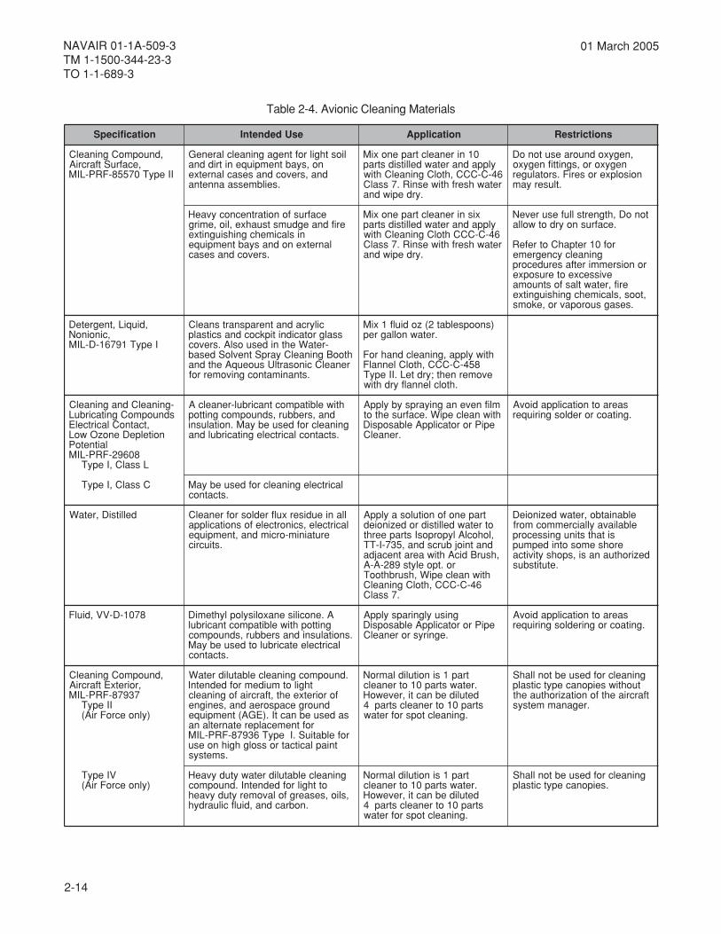
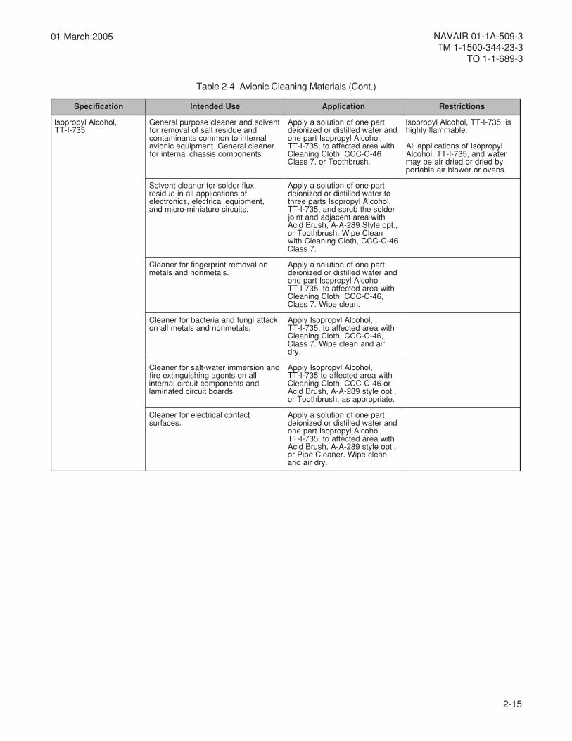
2.5.1.2. Materials Used for Cleaning. Table 2-4contains a list and description of the authorized cleaningmaterials for avionic equipment. Cleaning can beaccomplished as follows:
CAUTION
Some of the materials identified in Table 2-4can create hazardous conditions or damageequipment unless used strictly in theapplications and manner described. Authorizedalternative materials are included in thismanual, where applicable, to allow for potentialsupply shortages.
a. Solvent cleaning - solvents are effective indissolving grease and oil. Solvents can be applied bywiping, brushing, soaking, or spraying.
2-14
NAVAIR 01-1A-509-3TM 1-1500-344-23-3TO 1-1-689-3
01 March 2005
noitacificepS esUdednetnI noitacilppA snoitcirtseR
,dnuopmoCgninaelC,ecafruStfarcriA
IIepyT07558-FRP-LIM
liosthgilroftnegagninaelclareneGno,syabtnempiuqenitriddnadna,srevocdnasesaclanretxe
.seilbmessaannetna
01nirenaelctrapenoxiMylppadnaretawdellitsidstrap
64-C-CCC,htolCgninaelChtiwretawhserfhtiwesniR.7ssalC
.yrdepiwdna
,negyxodnuoraesutonoDnegyxoro,sgnittifnegyxo
noisolpxeroseriF.srotaluger.tluseryam
ecafrusfonoitartnecnocyvaeHerifdnaegdumstsuahxe,lio,emirg
nislacimehcgnihsiugnitxelanretxenodnasyabtnempiuqe
.srevocdnasesac
xisnirenaelctrapenoxiMylppadnaretawdellitsidstrap64-C-CCChtolCgninaelChtiwretawhserfhtiwesniR.7ssalC
.yrdepiwdna
tonoD,htgnertsllufesureveN.ecafrusnoyrdotwolla
rof01retpahCotrefeRgninaelcycnegreme
ronoisremmiretfaserudecorpevissecxeoterusopxe
erif,retawtlasfostnuoma,toos,slacimehcgnihsiugnitxe
.sesagsuoropavro,ekoms
,diuqiL,tnegreteD,cinoinoN
IepyT19761-D-LIM
cilyrcadnatnerapsnartsnaelCssalgrotacidnitipkcocdnascitsalp
-retaWehtnidesuoslA.srevochtooBgninaelCyarpStnevloSdesabrenaelCcinosartlUsuoeuqAehtdna
.stnanimatnocgnivomerrof
)snoopselbat2(zodiulf1xiM.retawnollagrep
htiwylppa,gninaelcdnahroF854-C-CCC,htolClennalF
evomerneht;yrdteL.IIepyT.htolclennalfyrdhtiw
-gninaelCdnagninaelCsdnuopmoCgnitacirbuL
,tcatnoClacirtcelEnoitelpeDenozOwoL
laitnetoP80692-FRP-LIM
LssalC,IepyT
htiwelbitapmoctnacirbul-renaelcAdna,srebbur,sdnuopmocgnittop
gninaelcrofdesuebyaM.noitalusni.stcatnoclacirtcelegnitacirbuldna
mlifnevenagniyarpsybylppAhtiwnaelcepiW.ecafrusehtot
epiProrotacilppAelbasopsiD.renaelC
saeraotnoitacilppadiovA.gnitaocroredlosgniriuqer
CssalC,IepyT lacirtcelegninaelcrofdesuebyaM.stcatnoc
dellitsiD,retaW llanieudiserxulfredlosrofrenaelClacirtcele,scinortcelefosnoitacilppa
erutainim-orcimdna,tnempiuqe.stiucric
trapenofonoitulosaylppAotretawdellitsidrodezinoied,lohoclAlyporposIstrapeerht
dnatniojburcsdna,537-I-TT,hsurBdicAhtiwaeratnecajda
ro.tpoelyts982-A-AhtiwnaelcepiW,hsurbhtooT
64-C-CCC,htolCgninaelC.7ssalC
elbaniatbo,retawdezinoieDelbaliavayllaicremmocmorf
sitahtstinugnissecorperohsemosotnidepmup
dezirohtuanasi,spohsytivitca.etutitsbus
8701-D-VV,diulF A.enocilisenaxolisyloplyhtemiDgnittophtiwelbitapmoctnacirbul
.snoitalusnidnasrebbur,sdnuopmoclacirtceleetacirbulotdesuebyaM
.stcatnoc
gnisuylgnirapsylppAepiProrotacilppAelbasopsiD
.egnirysrorenaelC
saeraotnoitacilppadiovA.gnitaocrogniredlosgniriuqer
,dnuopmoCgninaelC,roiretxEtfarcriA
73978-FRP-LIMIIepyT
)ylnoecroFriA(
.dnuopmocgninaelcelbatulidretaWthgilotmuidemrofdednetnI
foroiretxeeht,tfarcriafogninaelcdnuorgecapsoreadna,senigne
sadesuebnactI.)EGA(tnempiuqeroftnemecalperetanretlana
rofelbatiuS.IepyT63978-FRP-LIMtniaplacitcatrossolghgihnoesu
.smetsys
trap1sinoitulidlamroN.retawstrap01otrenaelcdetulidebnacti,revewoHstrap01otrenaelcstrap4
.gninaelctopsrofretaw
gninaelcrofdesuebtonllahStuohtiwseiponacepytcitsalp
tfarcriaehtfonoitazirohtuaeht.reganammetsys
VIepyT)ylnoecroFriA(
gninaelcelbatulidretawytudyvaeHotthgilrofdednetnI.dnuopmoc
,slio,sesaergfolavomerytudyvaeh.nobracdna,diulfciluardyh
trap1sinoitulidlamroN.retawstrap01otrenaelcdetulidebnacti,revewoHstrap01otrenaelcstrap4
.gninaelctopsrofretaw
gninaelcrofdesuebtonllahS.seiponacepytcitsalp
Table 2-4. Avionic Cleaning Materials
2-15
NAVAIR 01-1A-509-3TM 1-1500-344-23-3
TO 1-1-689-3
01 March 2005
noitacificepS esUdednetnI noitacilppA snoitcirtseR
,lohoclAlyporposI537-I-TT
tnevlosdnarenaelcesopruplareneGdnaeudisertlasfolavomerrof
lanretniotnommocstnanimatnocrenaelclareneG.tnempiuqecinoiva
.stnenopmocsissahclanretnirof
trapenofonoitulosaylppAdnaretawdellitsidrodezinoied
,lohoclAlyporposItrapenohtiwaeradetceffaot,537-I-TT
64-C-CCC,htolCgninaelC.hsurbhtooTro,7ssalC
si,537-I-TT,lohoclAlyporposI.elbammalfylhgih
lyporposIfosnoitacilppallAretawdna,537-I-TT,lohoclA
ybdeirdrodeirdriaebyam.snevororewolbriaelbatrop
xulfredlosrofrenaelctnevloSfosnoitacilppallanieudiser
,tnempiuqelacirtcele,scinortcele.stiucricerutainim-orcimdna
trapenofonoitulosaylppAotretawdellitsidrodezinoied,lohoclAlyporposIstrapeerhtredlosehtburcsdna,537-I-TT
htiwaeratnecajdadnatnioj,.tpoelytS982-A-A,hsurBdicA
naelCepiW.hsurbhtooTro64-C-CCC,htolCgninaelChtiw
.7ssalC
nolavomertnirpregnifrofrenaelC.slatemnondnaslatem
trapenofonoitulosaylppAdnaretawdellitsidrodezinoied
,lohoclAlyporposItrapenohtiwaeradetceffaot,537-I-TT
,64-C-CCC,htolCgninaelC.naelcepiW.7ssalC
kcattaignufdnaairetcabrofrenaelC.slatemnondnaslatemllano
,lohoclAlyporposIylppAhtiwaeradetceffaot,537-I-TT
,64-C-CCC,htolCgninaelCriadnanaelcepiW.7ssalC
.yrd
dnanoisremmiretaw-tlasrofrenaelCllanostnegagnihsiugnitxeerifdnastnenopmoctiucriclanretni
.sdraobtiucricdetanimal
,lohoclAlyporposIylppAhtiwaeradetceffaot537-I-TTro64-C-CCC,htolCgninaelC
,.tpoelyts982-A-A,hsurBdicA.etairporppasa,hsurbhtooTro
tcatnoclacirtcelerofrenaelC.secafrus
trapenofonoitulosaylppAdnaretawdellitsidrodezinoied
,lohoclAlyporposItrapenohtiwaeradetceffaot,537-I-TT,.tpoelyts982-A-A,hsurBdicA
naelcepiW.renaelCepiPro.yrdriadna
Table 2-4. Avionic Cleaning Materials (Cont.)
2-16
NAVAIR 01-1A-509-3TM 1-1500-344-23-3TO 1-1-689-3
01 March 2005
b. Detergent/water cleaning - varyingconcentrations of detergent and water mixtures areused to remove dust, dirt, salt, grease, and oil.Detergent/water mixtures can be applied by wiping,brushing, soaking, and spraying.
c. Distilled or fresh water is used to dilute isopropylalcohol or detergents for use in cleaning. It may also beused to rinse or remove dust, dirt, salt, and cleaningsolutions. Application can be by wiping, brushing,soaking or spraying.
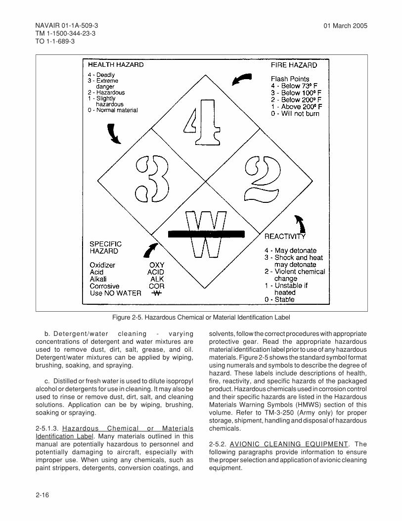
2-5.1.3. Hazardous Chemical or MaterialsIdentification Label. Many materials outlined in thismanual are potentially hazardous to personnel andpotentially damaging to aircraft, especially withimproper use. When using any chemicals, such aspaint strippers, detergents, conversion coatings, and
solvents, follow the correct procedures with appropriateprotective gear. Read the appropriate hazardousmaterial identification label prior to use of any hazardousmaterials. Figure 2-5 shows the standard symbol formatusing numerals and symbols to describe the degree ofhazard. These labels include descriptions of health,fire, reactivity, and specific hazards of the packagedproduct. Hazardous chemicals used in corrosion controland their specific hazards are listed in the HazardousMaterials Warning Symbols (HMWS) section of thisvolume. Refer to TM-3-250 (Army only) for properstorage, shipment, handling and disposal of hazardouschemicals.
2-5.2. AVIONIC CLEANING EQUIPMENT. Thefollowing paragraphs provide information to ensurethe proper selection and application of avionic cleaningequipment.
Figure 2-5. Hazardous Chemical or Material Identification Label

2-17
NAVAIR 01-1A-509-3TM 1-1500-344-23-3
TO 1-1-689-3
01 March 2005
2-5.2.1. General. Experimentation with cleaningsupport equipment is not an authorized practice.Damage to circuit components may result fromreactions to chemical solutions used in cleaningequipment. Avionic technicians should understand thefunctions, capabilities, and restrictions that apply toeach piece of cleaning equipment. This will preventdamage to avionic equipment and circuit componentsthat could result from improper use. Each piece ofcleaning equipment has been selected to performspecific functions. The following paragraphs identifythese intended functions and include general limitationsas applicable to each type of support equipment.
NOTE
Maintenance personnel should refer toappropriate cleaning equipment servicemanuals for specific operating instructions.
2-5.2.2. Aqueous Ultrasonic Cleaner. The followingis a list of the specific restrictions that apply to the useof Aqueous Ultrasonic Cleaner (Volume IV or V,Chapter 4).
CAUTION
Miniature and microminiature printed circuitboards (PCBs) may be susceptible to damagedue to ultrasonic frequency, power level, orboth. Due to the difficulty of determining whichcomponents may be damaged, ultrasoniccleaning of PCBs is not authorized unlessspecified. For additional information, refer toNAVAIR 01-1A-23 (Navy) or TO 00-25-234(Air Force).
2-5.2.2.1. The Aqueous Ultrasonic Cleaner is usedfor the removal of dirt, dust, salt spray deposits, andcorrosion products. This is achieved by ultrasonicscrubbing action in detergent and water solution.
a. The maximum operating temperature shall be130°F (54°C). The operating frequency used shall be20 kHz.
b. An additional function of the equipment is that of"presoaking" avionic equipment and components priorto the ultrasonic function.
CAUTION
Paper capacitors and paper-boundcomponents disintegrate in Detergent, MIL-D-16791, solution.
c. Detergent, MIL-D-16791 (Volume IV or V,Chapter 2) is the specified detergent. This detergentsolution shall be mixed 1 ounce (2 tablespoons)detergent to 1 gallon of water.
2-5.2.2.2. Sealed bearings, synchro and servobearings, instrument bearings, and similar deviceswith permanently lubricated bearings can experiencelubricant removal. These devices would be rendereduseless unless there are procedures specified in theapplicable service directives for relubrication. Whenpractical, avionic equipment containing such bearingscan be cleaned by aqueous ultrasonics if the bearingsare sealed in a plastic bag.
2-5.2.2.3. Sealed components (other thanhermetically sealed) can trap detergents and water.This may cause drying problems. In each case, thesealed component shall be opened to eliminatedetergent traps.
2-5.2.2.4. Thin metal foil types of gummed labels canloosen and separate.
2-5.2.3. Solvent Ultrasonic Cleaner. The following isa list of the specific restrictions that apply to the use ofSolvent Ultrasonic Cleaner (Volume IV or V, Chapter 4):
Alcohol, Isopropyl 6TT-I-735
2-5.2.3.1. The Solvent Ultrasonic Cleaner is used toremove light to heavy oil, grease, and hydraulic fluidcontamination by ultrasonic scrubbing in a solventsolution.
a. The maximum operating temperature shall bethe solvent’s boiling point. The maximum operatingfrequency used shall be 40 kHz.
b. Solvent, Cleaning, ENVIROSOLV 654CR(Volume IV or V, Chapter 2), may be used in solventultrasonic cleaner applications. MIL-PRF-680 Type III

2-18
NAVAIR 01-1A-509-3TM 1-1500-344-23-3TO 1-1-689-3
01 March 2005
may be used in the solvent ultrasonic cleaner if usedat room temperature.
2-5.2.3.2. Coaxial connector gaskets and otherneoprene rubber components are susceptible todamage by solvents. Also, cleaning solvents can wickup the coaxial leads causing condensation and dryingproblems. Where solvent ultrasonic cleaning is desired,equipment containing these devices can be cleanedonly if the coaxial connector can be sealed in a plasticbag.
2-5.2.3.3. Sealed bearings, synchro and servobearings, instrument bearings and similar devices withpermanently lubricated bearings shall be treated asspecified in paragraph 2-5.2.2.3.
2-5.2.3.4. Sealed components (components otherthan hermetically sealed) shall be treated as specifiedin paragraph 2-5.2.2.4.
2-5.2.3.5. Solvent, Cleaning can be used as a solventdegreaser. The restrictions as specified in thisparagraph apply to solvent degreaser functions. Thesolvent vapor rinse and solvent vapor drying functionsdo not use the ultrasonic frequency function. Therefore,they may be used to rinse and dry PCBs.
2-5.2.4. Water Base Solvent Spray Booth. Thefollowing is a list of the specific restrictions that applyto the use of Water Base Solvent Spray Booth(Volume IV or V, Chapter 3).
2-5.2.4.1. The Water Base Solvent Spray Booth isused to remove dirt, dust, salt spray deposits, and lightcorrosion products. This is achieved by a detergentand water spray system.
a. The spray equipment provides an air pressurepowered spray of detergent solution through a hand-held gun, using either filtered or tap water. It also candeliver a water rinse or drying jet of air through the gun.
b. A turntable is included, allowing 360 degreerotation of the avionic equipment being cleaned orrinsed.
c. The unit may be used as a "precleaner" prior toplacing the component in a detergent cleaning tank.
d. The unit also is used to rinse components afterthe application of detergent cleaning, abrasivecorrosion removal, or hand cleaning operations.
NOTE
Increasing the proportion of detergent in thesolution does not necessarily increase cleaningpower. This can, in some cases, reducecleaning effectiveness.
e. Detergent, MIL-D-16791 (Volume IV or V,Chapter 2), is the specified detergent. The detergentsolution shall be mixed 1 ounce (2 tablespoons)detergent to 1 gallon of water.
2-5.2.4.2. Sealed bearings, synchro and servobearings, instrument bearings, and similar deviceswith permanently lubricated bearings shall be treatedas specified in paragraph 2-5.2.2.3.
2-5.2.4.3. Sealed components (other thanhermetically sealed) shall be treated as specified inparagraph 2-5.2.2.4.
2-5.2.5. Abrasive Tools. The following is a list of thespecific restrictions that apply to the use of abrasivetools.
2-5.2.5.1. Mono-Basic Sodium Phosphate, AWWA-B504 (Volume IV or V, Chapter 2), or Glass Beads,MIL-G-9954 (Volume IV or V, Chapter 2), used inabrasive tools are easily trapped in miniature andmicrominiature female edge connectors. When use ofa Blast Cleaning Cabinet on internal chassiscomponents is necessary, the connectors shall besealed with Pressure Sensit ive Tape,SAE-AMS-T-21595, Type I (Volume IV or V, Chapter 2).Ensure that the tape is removed following cleaning.
2-5.2.5.2. Delicate metal surfaces are susceptible todamage if abrasive tools are not used with care. Onlyexperienced operators are authorized to use abrasivetools on avionic equipment.
2-5.2.5.3. Some miniature/microminiature PCBscontain devices sensitive to electrostatic discharge(ESD) that may be destroyed by the static chargecreated by abrasive agents used in abrasive tools. Inno case is a Blast Cleaning Cabinet or Portable Mini-Abrasive Unit (Volume IV or V, Chapter 4) authorizedfor cleaning or corrosion removal of components whereESD devices are installed.
2-5.3. AVIONIC CLEANING PROCEDURES. Thefollowing paragraphs provide information to ensurethe proper cleaning of avionic equipment.
2-19
NAVAIR 01-1A-509-3TM 1-1500-344-23-3
TO 1-1-689-3
01 March 2005
2-5.3.1. General. Contamination is responsible forcorrosion problems in avionic equipment. Cleaningcan prevent many of these problems and is the firstlogical step following inspection. Cleanliness is veryimportant in maintaining the functional integrity andreliability of avionic systems. Dirt may be eitherconductive or insulating. As a conductor, it may provideundesired electrical paths, while as an insulator it mayinterfere with proper operation.
2-5.3.2. Cleaning Methods Selection Criteria. Theselection of the cleaning method is a decision to bemade by the work center supervisor or equipmentoperator. Certain circuit components can be damagedby support equipment. This paragraph is intended toemphasize the limitations involved in using supportequipment on certain avionic equipment andcomponents. The method used shall be based on:
NOTE
Always select the mildest method of cleaningthat will accomplish the task.
a. Type and extent of the contamination and/orcorrosion.
b. Accessibility to the contamination and/orcorrosion.
c. Type of avionic equipment.
CAUTION
Acid cleaners shall not be used on avionicequipment.
NOTE
Deionized or distilled water is required incleaning operations involving soldering andsome conformal coating applications. Ifdeionized or distilled water is not availablelocally, distilled water may be procured underthe stock number listed in Volume IV or V,Chapter 2.
2-5.3.3. Hazards of Cleaning. It is a good maintenancepractice to use the mildest cleaning method that willensure proper decontamination. It is also importantthat the correct cleaning solution and cleaning materialsare used to avoid damaging avionic equipment andcomponents. The following emphasizes some of thehazards of cleaning:
a. Cleaning solvents or materials can be trapped increvices or seams. This may interfere with laterapplications of protective coatings as well as causingcorrosion.
b. Vigorous or prolonged scrubbing of laminatedcircuit boards can cause damage to the boards.
c. Certain cleaning solvents soften conformalcoatings, wire coverings, acrylic panels, and somecircuit components
2-5.3.4. When to Clean. The immediate removal ofcorrosion on avionic equipment and surroundingstructure is always a high priority in corrosion control.Therefore, immediate cleaning shall be accomplishedafter avionic equipment has been exposed to any ofthe following conditions:
a. Adverse weather conditions or salt-water spray(open canopy, equipment door, or panel).
b. Fire-extinguishing agents.
c. Spilled electrolyte or corrosion deposits aroundbattery terminals and the general vicinity of the batteryarea.
d. Corrosion removal or component repair.
2-5.3.5.Precleaning Treatment.
a. Disconnect power supply.
b. Ensure drain holes are open.
c. Remove covers or panels.
d. Disassemble where practical.
e. Use only authorized materials.
f. Ensure compatibility of materials prior to use.
g. Mask and protect accessories or components toprevent entrance of water, solvents or cleaningcomponents.
2-5.3.6. Cleaning and Drying Restrictions. Certaincircuit components create potential problems duringcleaning and drying. In most cases, the problems canbe overcome prior to cleaning the equipment. Thegreatest potential for problems is the circuit component
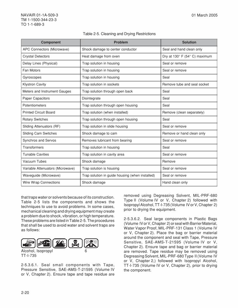
2-20
NAVAIR 01-1A-509-3TM 1-1500-344-23-3TO 1-1-689-3
01 March 2005
that traps water or solvents because of its construction.Table 2-5 lists the components and shows thetechniques to use to avoid problems. In some cases,mechanical cleaning and drying equipment may createa problem due to shock, vibration, or high temperature.These problems are listed in Table 2-5. The proceduresthat shall be used to avoid water and solvent traps areas follows:
Alcohol, Isopropyl 6TT-I-735
2-5.3.6.1. Seal small components with Tape,Pressure Sensitive, SAE-AMS-T-21595 (Volume IVor V, Chapter 2). Ensure tape and tape residue are
removed using Degreasing Solvent, MIL-PRF-680Type II (Volume IV or V, Chapter 2) followed withIsopropyl Alcohol, TT-I-735 (Volume IV or V, Chapter 2)prior to drying the equipment.
2-5.3.6.2. Seal large components in Plastic Bags(Volume IV or V, Chapter 2) or seal with Barrier Material,Water Vapor Proof, MIL-PRF-131 Class 1 (Volume IVor V, Chapter 2). Place the bag or barrier materialaround the component and seal with Tape, PressureSensitive, SAE-AMS-T-21595 (Volume IV or V,Chapter 2). Ensure tape and bag or barrier materialare removed. Tape residue may be removed usingDegreasing Solvent, MIL-PRF-680 Type II (Volume IVor V, Chapter 2,) followed with Isopropyl Alcohol,TT-I-735 (Volume IV or V, Chapter 2), prior to dryingthe component.
Table 2-5. Cleaning and Drying Restrictions
tnenopmoC melborP noituloS
)evaworciM(srotcennoCCPA rotcudnocretnecotegamadkcohS ylnonaelcdnahdnalaeS
srotceteDlatsyrC nevomorfegamadtaeH mumixam)C°45(F°031tayrD
)lacisyhP(seniLyaleD gnisuohninoitulosparT evomerrolaeS
srotoMnaF gnisuohninoitulosparT evomerrolaeS
sepocsoryG gnisuohninoitulosparT laeS
ytivaCnortsylK stekcosninoitulosparT tekcoslaesdnaebutevomeR
seguaGtnemurtsnIdnasreteM kcabnepohguorhtnoitulosparT laeS
sroticapaCrepaP etargetnisiD laeS
sretemoitnetoP gnisuohnepohguorhtnoitulosparT laeS
draoBtiucriCdetnirP )dellatsninehw(noitulosparT )yletarapesnaelc(evomeR
sehctiwSyratoR gnisuohnepohguorhtnoitulosparT laeS
)FR(srotaunettAgnidilS gnisuohedilsninoitulosparT evomerrolaeS
sehctiwSmaCgnidilS macotegamadkcohS ylnonaelcdnahroevomeR
sovreSdnasorhcnyS gniraebmorftnacirbulsevomeR evomerrolaeS
sremrofsnarT gnisuohninoitulosparT laeS
seitivaCelbanuT aeraytivacninoitulosparT evomerrolaeS
sebuTmuucaV egamadkcohS evomeR
)evaworciM(srotaunettAelbairaV gnisuohsinoitulosparT evomerrolaeS
)evaworciM(ediugevaW )dellatsninehw(gnisuohediugninoitulosparT evomerrolaeS
snoitcennoCparWeriW egamadkcohS ylnonaelcdnaH
2-21
NAVAIR 01-1A-509-3TM 1-1500-344-23-3
TO 1-1-689-3
01 March 2005
NOTE
Repair conducted by Organizational/Unit orIntermediate Maintenance Activities shall notinclude disassembly of avionic equipmentbeyond authorized limits established by theparent service organization. Cleaning,corrosion repair, treatment and preservationof equipment shall include all cables,harnesses, and hardware furnished with eachpiece of equipment.
2-5.3.6.3. In some cases the component may beremoved from the equipment without too much difficulty.When this is possible, the removed component shallbe cleaned separately.
2-5.3.7. Hand Cleaning Methods. Hand methods shallbe used for cleaning small, delicate, confined surfaceswhere parts cannot tolerate other means of cleaning.Also, hand methods shall be used when accessories/facilities for other methods that are not available. Handcleaning methods for avionics utilize the following(refer to Volume IV or V):
a. Cloth, CCC-C-46.
b. Cheesecloth, CCC-C-440.
c. Cotton tip applicator.
d. Acid brush, A-A-289.
e. Toothbrush.
f. Brush.
g. Lint-free cloth, A-A-59323.
h. Cotton flannel, CCC-C-458.
i. Plastic manual spray bottle.
2-5.3.8. Fingerprint Removal. The fats and oils causedby fingerprints are highly corrosive.
Alcohol, Isopropyl 6TT-I-735
WARNING
Do not use synthetic fiber wiping cloths withIsopropyl Alcohol, TT-I-735, due to its lowflash point. Dry fiber wiping cloths will cause astatic charge buildup and can result in a fire.
2-5.3.8.1. Apply a mixture of one part IsopropylAlcohol, TT-I-735 (Volume IV or V, Chapter 2), andone part distilled water to affected areas with CleaningCloth, CCC-C-46 (Volume IV or V, Chapter 2), AcidBrush A-A-289 (Volume IV or V, Chapter 3),Toothbrush, or any brush as appropriate.
2-5.3.8.2. Wipe or scrub affected area unti lcontaminants have been dislodged.
2-5.3.8.3. Remove residue by blotting or wiping withCleaning Cloth, CCC-C-46 (Volume IV or V, Chapter 2).Inspect affected areas for signs of residues andcontaminants.
2-5.3.8.4. Discard contaminated cloths and solventsin approved disposal containers after cleaningoperation to avoid contamination of other components.
2-5.3.8.5. Repeat process until all contaminants areremoved.
2-5.3.9. Cleaning and Removal of Solder FluxResidue. Solder flux residue is present in all solderoperations. This residue will cause corrosion if anelectrolyte is present. Use of cleaning solvents that donot damage associated wiring circuit components, orlaminated circuit board coatings is required. Thepresence of solder flux can be detected by usingUltraviolet Light.
CAUTION
Prior to ultraviolet (UV) light inspection, avionicequipment must be examined for ErasableProgrammable Read Only Memory (EPROM)components.
2-5.3.9.1. EPROMs have windows that are usuallycovered with an aluminum foil mask or black tape.Visually examine EPROMs to ensure the tape or foil
2-22
NAVAIR 01-1A-509-3TM 1-1500-344-23-3TO 1-1-689-3
01 March 2005
has not lifted from the windows. Do not place EPROMsnear a UV light source for long periods of time. Naturalsunlight includes ultraviolet light, although at a muchlower intensity than the light from the ultraviolet lamp.Extended exposure of EPROM and ESD devices tosunlight can degrade these devices.
WARNING
Ultraviolet Light is harmful to eyes when usedwithout the filter. Do not use a cracked ordamaged filter.
2-5.3.9.2. Inspect component for presence of solderflux residue using ultraviolet light (Volume IV or V,Chapter 3). Under ultraviolet light, traces of solder fluxresin appear as a fluorescent yellow to brownishresidue.
WARNING
Lead contained in solder can rub off onto aperson’s hands from a soldered joint. Leadoxide is a poison that is not eliminated by thebody and can accumulate over years ofexposure. Touching solder followed bysmoking or eating is a potential means ofingesting trace amounts of lead oxide. Washhands thoroughly following any soldering/desoldering operation.
Alcohol, Isopropyl 6TT-I-735
2-5.3.9.3. Solder flux residues shall be removed fromcircuit boards and circuit components in accordancewith Cleaning Track 1 (paragraph 2-4.10.). Use asolution of one part distilled water to three parts ofIsopropyl Alcohol, TT-I-735 (Volume IV or V,Chapter 2), to clean the affected area. Refer to ANSI/J-STD-001 for additional information on solder fluxesand soldering techniques.
2-5.3.9.4. Store critical circuit components notinstalled in equipment as specified in paragraph 9-2.4.Ensure EPROM devices have windows covered. Referto Chapter 8 for packaging information on ESD devices.
2-5.3.10. Cleaning and Removal of Silicone Lubricant.Remove silicone residue from surfaces as follows:
2-5.3.10.1 Wipe contaminated surface with CleaningCloth, CCC-C-46 Class 7 (Volume IV or V, Chapter 2),Acid Brush, A-A-289 (Volume IV or V, Chapter 3),Disposable Applicator (Volume IV or V, Chapter 3), orPipe Cleaner (Volume IV or V, Chapter 3), dampenedwith Cleaning Compound, MIL-PRF-85570 Type II (orMIL-PRF-87937 (Air Force)) or Cleaning Solvent(Volume IV or V, Chapter 2) until clean.
2-5.3.10.2 Dry surface with Cleaning Cloth, CCC-C-46, Class 7, Disposable Applicator, or Pipe Cleaner.
2-5.3.11. Cleaning and Removal of Bacteria and Fungi.Dirt, dust, and other airborne contaminants are leadingcontributors to bacteria and fungus (microbial) attack.The best defense against this form of attack is tomaintain cleanliness and, where possible, low humidity.Fungus and bacteria shall be removed from affectedareas as follows:
2-5.3.11.1. Mask air capacitors, relay contacts, openswitches, and tunable coils with Pressure SensitiveTape, SAE-AMS-T-21595 Type I (Volume IV or V,Chapter 2).
2-5.3.11.2. Treat affected areas in accordance withparagraph 2-5.3.8.
2-5.3.12. Cleaning and Removal of Dust, Dirt, Grease,and Oil. Dust and dirt shall be removed by wettingsurface with fresh water as follows:
Compound, Aircraft Cleaning 4MIL-PRF-85570
2-5.3.12.1. Apply a solution of one part AircraftCleaning Compound, Class I, MIL-PRF-85570, TypeII (Volume IV or V, Chapter 2) to ten parts distilledwater. Air Force may use MIL-PRF-87937 Type II or IVas an alternate cleaning compound.
2-5.3.12.2. Scrub affected areas of parts with Cleaningand Polishing Pad, Non-Abrasive (Volume IV or V,Chapter 2), Cleaning Cloth, CCC-C-46 (Volume IV orV, Chapter 2), Cloth, Cheese-Cloth, CCC-C-440(Volume IV or V, Chapter 2), Brush, Acid Swabbing,A-A-289 (Volume IV or V, Chapter 3), Toothbrush, orApplicator, Cotton Tipped (Volume IV or V, Chapter 3).
2-5.3.12.3. Wipe area with Cleaning Cloth, CCC-C-46.
2-23
NAVAIR 01-1A-509-3TM 1-1500-344-23-3
TO 1-1-689-3
01 March 2005
2-5.3.12.4. Rinse with clean, fresh water and by areawith Cleaning Cloth, CCC-C-46.
2-5.3.12.5. Remove grease and oil as specified inparagraph 2-5.3.12.1. Use a solution of one part AircraftCleaning Compound, MIL-PRF-85570, to ten parts ofdistilled water. Air Force may use MIL-PRF-87937Type II or IV as an alternate cleaning compound.
2-5.3.13. Surface Preparation. The true cleanliness ofbare metal surfaces after a cleaning process is verycritical to adhesion of any subsequent coating material.For example, a chemical conversion coating, paint, dryfilm lubricant, or adhesive needs a clean surface toadhere properly. One method used to identify when asurface is clean enough for good adhesion is theWater Break Test. The procedure is described inVolume II (Navy and Army) and TO 1-1-691 (Air Force).This test is appropriate for use at the time of the finalclear water rinse. This usually follows cleaning of anybare metal surface for adhesion.
2-5.3.14. Special Considerations. Dust, fingerprints,surface oxides, contaminants, or other foreign materialon a surface, can undo preservation provided byprotective coatings. Specific avionic subsystems,equipment, and components shall be cleaned asspecified in Chapter 6.
2-5.3.15. Post-Cleaning Procedures. When aerosolspray, compressed air, or air from dryers is used onESD devices, precautions in NAVAIR 01-1A-23 (Navy)or TO 00-25-234 (Air Force) shall be followed.
2-5.3.15.1. After completion of the cleaning steps,reinspect the affected area for signs of residue, surfacefilm, or water.
2-5.3.15.2. If the affected area is not clean, repeat thecleaning procedures. Water-displacement,preservation, and lubrication shall follow the cleaningand drying steps in preventive maintenance.
2-6. DRYING EQUIPMENT AND PROCEDURES.
2-6.1. GENERAL. Drying time depends on thecomplexity of the equipment/component being dried.The more complex the individual component, the longerthe drying time. Another consideration in drying time isthe humidity or moisture content of the air where thedrying oven is operated. The higher the moisturecontent of ambient air, the longer the drying time.
2-6.2. DRYING PREPARATION. Prior to placing acomponent in a drying oven, remove all covers, lids,and open all doors. Ensure any pressure sensitivetape and protective plastic bags used during thecleaning process have been removed.
CAUTION
The motion of air against other materials cangenerate static charges that degrade or destroyESD devices. Care must be exercised duringhandling/repair of these items. Use therecommended shop practices outlined inChapter 8.
2-6.3. AIR DRYING. Air drying is usually adequate forhousings, covers, and some hardware. This method isnot considered adequate for more complex equipmentor components that may contain cavities or moisturetraps.
2-6.4. DRYING WITH HOT AIR BLOWER. Proceduresfor the use of hot air blowers are as follows:
WARNING
Compressed air used for drying can createairborne particles that may enter the eyes.Pressure shall not exceed 10 psi. Eyeprotection is required.
2-6.4.1. Blow off excess water with dry air or drynitrogen at not more than 10 psi pressure. Deflect airoff interior back and sides of enclosure to diffuse jet.
CAUTION
Portable air blowers, hot air blowers, hairdryers, and similar drying devices may causefires when used in or around aircraft. Hot AirGun, Raychem, HT-900, or an equivalentspark-proof substitute, is the only authorizedhot air gun to be used in and around aircraft.Hot Air Gun, A-A-59435, is authorized for shopuse only.
2-6.4.2. Dry the equipment with a Hot Air Gun, A-A-59435 (Volume IV or V, Chapter 3), or Hot Air Gun,Raychem, HT-900 (Volume IV or V, Chapter 3), asappropriate. Surfaces should not be heated with thehot air gun above 130°F when drying equipment.
2-24
NAVAIR 01-1A-509-3TM 1-1500-344-23-3TO 1-1-689-3
01 March 2005
2-6.5. DRYING WITH CIRCULATING AIR DRYINGOVEN. The Circulating Air Drying Oven, (Volume IV orV, Chapter 3) is used to dry small electrical andelectronic components (such as unpressurizedinstruments), control boxes, PCBs, and similar devices.The circulating air drying oven shall never be operatedabove 130°F (54°C) when drying avionic equipment orcomponents. Damage may result from overheating ofdiscrete electronic circuit components. Procedures forthe operation of the circulating air drying oven are asfollows:
2-6.5.1. Blow off excess water with dry air or drynitrogen at no more than 10 psi pressure. Deflect air offinterior back and sides of enclosure to diffuse jet.
CAUTION
Older circulating air drying ovens may haveuncalibrated dials or controls for setting theoven temperature. These ovens shall becalibrated so that the 130°F (54°C) temperaturesetting is "red lined" on the dial or control.
2-6.5.2. Set the temperature control at a maximum of130°F (54°C).
2-6.5.3. Place the component(s) in the oven and closethe door. If a timer is available, set it for 3 to 4 hours.
NOTE
Opening and closing the oven door duringdrying will increase drying time. This is due todiffusion of hot, dry air in the oven cabinet withcooler, more humid air from the surroundingshop.
2-6.5.4. Upon completion of the drying cycle, removethe component(s).
2-6.6. DRYING WITH FORCED AIR OVEN. TheForced Air Drying Oven (Volume IV or V, Chapter 3) isthe most efficient of the drying ovens. This unit can beused to dry all types and sizes of equipment andcomponents. The procedures for the operation of theforced air drying oven are as follows:
CAUTION
The motion of air against other materials cangenerate static charges that degrade or destroyESD devices. Care must be exercised duringhandling/repair of these items. Use therecommended shop practices outlined inChapter 8.
2-6.6.1. Blow off excess water with dry air or drynitrogen at no more than 10 psi pressure. Deflect airoff interior back and sides of enclosure to diffuse jet.
CAUTION
Check the temperature dial (or controlcalibration) periodically to ensure thetemperature setting is correctly calibrated.
2-6.6.2. Set the temperature control at a maximum of130°F (54°C).
2-6.6.3. Place the component(s) in the oven and closethe door. If a timer is available, set it for 1 to 2 hours.Opening and closing the oven door during drying willincrease the drying time slightly but not appreciably.This is considered one of the advantages of the forcedair drying oven over the circulating air type.
2-6.6.4. Upon completion of the drying cycle, removethe component(s).
2-6.7. DRYING WITH VENTED OVEN (BULBTYPE). Vented drying oven procedures are as follows:
2-6.7.1. Blow off excess water with not more than 10psi dry air pressure or dry nitrogen. Deflect air offinterior, back, and sides of enclosure to diffuse jet.
2-6.7.2. Dry the equipment at approximately 130°F(54°C) for 3 to 4 hours.
2-6.8. DRYING WITH VACUUM OVEN. Vacuum ovendrying procedures are as follows:
2-25
NAVAIR 01-1A-509-3TM 1-1500-344-23-3
TO 1-1-689-3
01 March 2005
CAUTION
The motion of air against other materials cangenerate static charges that degrade or destroyESD devices. Care must be exercised duringhandling/repair of these items. Use therecommended shop practices outlined inChapter 8.
2-6.8.1. Blow off excess water with not more than 10psi dry air pressure or dry nitrogen. Deflect air offinterior, back, and sides of enclosure to diffuse jet.
2-6.8.2. Dry the equipment at approximately 130°F(54°C) and 26 inches of mercury (Hg) for 1 to 2 hours.
2-7. LUBRICANTS.
2-7.1. GENERAL. Lubrication of equipment performsseveral important functions. It not only prevents wearbetween moving parts but provides a corrosion barrierand chemically inhibits corrosion. Particular attentionshould be given to lubrication points, hinges, andlatches. Inspect for signs of lubricant breakdown; forexample, caking of grease, loss of oil or dry filmlubricant, or evidence of contamination.
2-7.2. REQUIREMENTS. Maintenance personnelshould refer to the applicable service directives forspecific lubrication requirements.
2-25/(2-26 Blank)

3-1
NAVAIR 01-1A-509-3TM 1-1500-344-23-3
TO 1-1-689-3
01 March 2005
CHAPTER 3INSPECTION AND CORROSION PRONE AREAS
3-1. CORROSION PRONE AREAS.
3-1.1. GENERAL. There are certain corrosion-proneareas common to all aircraft. For example, the bilgearea of an airframe is particularly susceptible tomoisture intrusion. This area is where cable runs, wirebundles, coaxial cables, lights, and antenna areinstalled. It is almost impossible to seal the equipmentand components in this area against moisture and fluidintrusion. Even though the bilge is a rather obviousproblem area, there are other areas of concern, suchas structural, electromechanical, and electroniccomponents.
3-1.1.1. Frequent inspections and spot checks arefundamental to the preventive maintenance aspects ofan avionic corrosion control program. . This should bedone by personnel familiar with the detection, analysis,and treatment of corrosion and microbial attack.
3-1.1.2. The most useful tool for detection of corrosionis the human eye. Visual inspection can usually revealthe existence of corrosion and microbial attack in theirinitial stages. This is usually when corrosion treatmentis relatively easy. When corrosion or microbial attackis apparent, a specific and immediate program forcorrective treatment involves paint and/or surfacecoating removal and cleaning. In addition, removal ofcorrosion/fungus, restoration of surfaces, and promptapplication of protective coatings/paint finishes arealso required. Each type of corrosion has its ownpeculiarities and requires special treatment.
3-1.2. MOISTURE AND OTHER FLUID INTRUSIONSOURCES. The flexible airframe of modern militaryaircraft prevents effective sealing. Equipment baydoors, access panels, ducts, static pressure sensors,and other fuselage openings allow moisture intrusion.As a result, moisture and other fluids pool in water-traps or bilge areas not designed for their presence. Inaddition, the mission profile, mode of operation, andfield climatic exposure extremes compound anyproblems associated with the inadequateenvironmental integrity of the airframe. When waterpenetrates the airframe, these lines and cables helpdirect moisture and fluid contaminants to avionicequipment and components. A simple hydraulic linecan direct water many feet through the airframe anddeposit it on equipment. This often occurs in areas ofthe airframe that are assumed to be protected. A wire
bundle can carry moisture into the avionic equipmenthousing via an electrical connector backshell. Militaryaircraft are generally susceptible to moisture and otherfluid intrusion originating from the following sources:
a. Rainstorms
b. Water washdown systems
c. Hand washing cycles
d. Sea water spray
e. Environmental control systems
f. Hydraulic, fuel, and engine oil, anti-icing andcoolant line leaks
g. Condensation from cyclic temperature andpressure variation
h. Emergency firefighting materials
i. Solvents, detergents, strippers, and othercleaning materials
3-1.3. STRUCTURAL. Parts including housings,covers, supports, brackets, cabinets, and chassis arerequired for structural support. Corrosion on theseparts should be treated to eliminate long termdeterioration. Severe corrosion usually results fromcoatings failure and subsequent attack on exposedmetal. The corrosion is caused by handling orenvironmental attack such as moisture and/or microbialcontamination. Major repairs should be performed atDepot level. Preventive maintenance, corrosion control,and touchup procedures may be accomplished at theIntermediate maintenance level. Organizational/Unitmaintenance level can provide minor assistance withthese procedures.
3-1.4. ELECTROMECHANICAL. Motion is an integralfunction of electromechanical switches, relays,potentiometers, motors, generators, and synchro parts.Failure of these parts normally does not occur duringoperation. The friction tends to keep the critical surfacesclean enough to permit operation. Storage or nonusein certain environments tends to promote corrosion ofthese parts. The principle causes of malfunction aredust, condensates, resultant corrosion products

3-2
NAVAIR 01-1A-509-3TM 1-1500-344-23-3TO 1-1-689-3
01 March 2005
(oxides) and organic contaminant films. Insulatingfilms form during nonuse and prevent startup ofequipment. Once the equipment is activated, theinsulating film is removed by friction between surfaces.
3-1.5. ELECTRONIC. Moisture and contaminationpenetrate into electronic systems causing manydetrimental effects, corrosion being one of these. Inmost electronic systems, circuit areas have beenminimized for faster signal processing and higherdensity. This means that most circuit paths are thin, orsmall in cross-sectional area, and that individual circuitpaths are close together. In such systems, traceamounts of moisture and contamination may causesystem failure. For example, if the aluminum surface ofan integrated circuit (IC) is contaminated, affectedcircuit paths may become blocked. This extremesensitivity requires special caution when dealing with
corrosion in electronic systems. The typical effects ofcorrosion on avionic equipment are listed in Table 3-1.
3-1.6. SPECIAL CONSIDERATIONS. The control ofcorrosion in avionic systems is not unlike that inairframes. Procedures used for airframes are applicableto avionics with appropriate modifications. The generaldifferences in construction and procedures betweenairframe and avionics relative to corrosion control areas follows:
a. Avionics rely on less durable protection systems.
b. Very small amounts of corrosion can makeavionic equipment inoperative, as compared toairframes.
c. Dissimilar metals are often in electrical contact.
Table 3-1. Effects of Corrosion on Avionic Equipment
tnenopmoC edoMeruliaF
smetsySannetnA noitaroiretedlarutcurtsdnastnatsnoctiucricnisegnahcrostrohS
seirettaB dna,stnioptcatnoclacirtcelefoeruliaf,slanimrettaecnatsiserhgiHslangistipkcocsuoenorrE.gnitnuomfonoitaroiretedlarutcurts
sraBsuB seruliaflacirtcelednalarutcurtS
semaFtnuoMdna,srevoC,sgnisuoH,sissahC noitaroiretedlarutcurtsdna,hsiniffossol,gnittip,noitanimatnoC
seniLlaixaoC fonoitaroiretedlarutcurtsdna,slangisfossol,snoitautculfecnadepmIsrotcennoc
gninuTlacirtcelEdnalacinahceMxoBlortnoCstcatnoCrotoMdnaegakniL
noitcelesycneuqerfytluafdnanoitarepotnettimretnI
sthgiLgniWdnaspmalyalpsiD seruliaflacirtcelednalacinahcem,noitarepotnettimretnI
seniLmetsySgnilooCdiulF ssolrewopdna,gnittip,steksagfoeruliaF
srotcennoCelbaCnip-itluM laesretawdna,noitarepotnettimretni,ecnatsiserdesaercni,strohSnoitaroireted
selcatpeceRdnaskcaJ,srotcennoC,sgulP decuderdna,noitarepotnettimretni,ecnatsiserdesaercni,strohSytilibailermetsys
selbaCrewoP noitaroiretedrotcennoc/eriwdna,noitalusnifonoitargetnisiD
stiucriCerutainimorciMdnastiucriCdetnirP seruliafmetsysdnatnenopmoc,ecnatsiserdesaercni,strohS
smetsySgnihctiwSdnayaleR ssollangisdna,noitarepotnettimretni,strohs,eruliaflacinahceM
stroppuSdnastnuoMkcohS ssenevitceffekcohsfossoldnanoitaroireteD
sparTretaW noitaroiretedlarutcurtS
sediugevaW dnaycneiciffefonoitcuder,gnittip,erutsiomtsniagaytirgetnifossoLnoitaroiretedlarutcurts

3-3
NAVAIR 01-1A-509-3TM 1-1500-344-23-3
TO 1-1-689-3
01 March 2005
d. Stray electrical currents can cause corrosion.
e. Active metals and dissimilar metals in contactare often unprotected.
f. Closed boxes can produce condensation vianormal temperature changes during flight.
g. Avionic systems have many areas that trapmoisture.
h. Hidden corrosion is difficult to detect in manyavionic systems.
i. Many materials used in avionic systems aresubject to attack by bacteria and fungi.
j. Organic materials are often used that, whenoverheated or improperly or incompletely cured, canproduce vapors. These vapors are corrosive toelectronic components and damaging to coatings andinsulators.
3-2. INSPECTION PROCESS.
3-2.1. GENERAL. Frequent corrosion inspections areessential to the overall corrosion control program. Byearly detection, identification, and treatment, the costsresulting from corrosion are minimized. Without regularsystematic inspections, corrosion will seriously damageavionic equipment. The following paragraphs describesome of the basic aspects of visual inspection forcorrosion and the telltale signs associated with varioustypes of corrosion damage.
3-2.2. INSPECTION FACTORS. Calendar-based andphase maintenance inspections shall be in accordancewith parent service or command directives. However,extreme humidity, temperature, atmospheric conditionsand time shall be considered when determining thefrequency of corrosion inspections. The followingfactors shall be considered when establishing localinspection intervals:
a. Operational environment.
b. Known corrosion-prone areas such as batterycomponents, ram air turbines, and electrical bonds.Figure 3-1 shows corrosion caused by a blowncapacitor.
c. Length of storage time, with respect to equipmentand components. A corroded frequency test set is
shown in Figure 3-2. This corrosion occurred while instorage.
d. Length of time aircraft is nonoperational.
e. Nonpressurized equipment and equipment bays.
f. Antenna and externally mounted avionicpackages such as electronic countermeasure (ECM)pods.
g. Equipment mounted in water entrapment areas.
h. Equipment susceptible to particularly harshenvironments, such as sonobuoys and magneticanomaly detection (MAD) systems.
Figure 3-1. Corrosion Caused by Blown Capacitor Acid
Figure 3-2. Frequency Test Set CorrodedWhile in Storage

3-4
NAVAIR 01-1A-509-3TM 1-1500-344-23-3TO 1-1-689-3
01 March 2005
i. System Fluids. The coolant of high power radarproduces a black substance called "black plague" thatadheres to immersed metal surfaces and adverselyaffects heat transfer properties. Waveguides aresusceptible to this black plague.
j. Corrosion Effects of Solder Flux. Solder fluxresidues may be conductive as well as corrosive. Theyare often "tacky", collecting dust which can absorbmoisture and create current leakage paths. Solder fluxresin appears as an amber-colored globule, drip, ortail, at or near, the solder joint. Ultraviolet light may beused to detect the flux resin residue. Under theUltraviolet light, traces of flux appear as a fluorescentyellow to light brown residue.
NOTE
Specific inspection criteria for individual typesof avionic subsystems, equipment, andcomponents are listed in Chapter 6.
3-2.3. GENERAL INSPECTION PROCEDURE. Thefollowing general procedures shall be used for avioniccorrosion inspection:
a. Clean area or component by wiping with cleaningcloth, CCC-C-46, Class 7 (Vol IV or V, Chapter 2) toremove interfering soil or contaminant.
b. Use a 10X magnifying glass (Vol IV or V, Chapter3) to inspect for evidence of corrosion and determineextent of damage. In the case of miniature ormicrominiature circuit boards and components, usethe appropriate microscope, as necessary.
c. Refer to the applicable service directives fordamage limits.
3-2.4. WATER INTRUSION INSPECTION. Theavionic technician should routinely inspect the interiorof equipment bays for evidence of water intrusion. Anyevidence of corrosion damage should be reported sothat appropriate maintenance action can be scheduled.To determine and eliminate the source of waterintrusion:
a. Verify installation of fasteners. Replace asrequired.
b. Inspect form-in-place gasket. Repair or replaceas required in accordance with the applicable structuralrepair manual.
c. Verify water drains are open and clear.
d. Prepare compartment with "witness material"such as blotter paper, paper towels, etc. The "witnessmaterial" shall be placed in a manner that will indicatea leakage path during the water test.
e. Secure compartment doors.
f. Where fresh water is in adequate supply, applywater with a hose to the exterior surface forapproximately 5 minutes. Where water is in shortsupply, slowly pour a bucket of fresh water over theexterior surface.
g. Allow 3 to 5 minutes for water to drain.
h. Open compartment doors and examine "witnessmaterial" for signs of water.
Adhesive/Sealant, Silicone RTV, 1Non-CorrosiveMIL-A-46146
Sealing and Coating Compound 2(polysulfide)MIL-PRF-81733
i. If leaks are observed, they shall be sealed withMIL-A-46146 or MIL-PRF-81733 (Vol IV or V, Chapter2). MIL-PRF-81733 shall be used when sealant will bein contact with fluids such as coolants, fuel, or hydraulicoil.

3-5
NAVAIR 01-1A-509-3TM 1-1500-344-23-3
TO 1-1-689-3
01 March 2005
NOTEWhere torquing is required to tighten hardware,refer to specific technical manual for propertorque values.
Compound, Corrosion Preventative 3Water-DisplacingMIL-C-81309
j. (Navy/Army Only) Where applicable, apply MIL-C-81309 Type II (Vol IV, Chapter 2) to threads offasteners before reinstallation.
k. (Air Force Only) Where applicable apply MIL-C-81309 Type II or MIL-L-87177 (Vol V, Chapter 2) tothreads of fasteners before reinstallation.
l. Secure access/compartment doors.
m. Repeat water test until no leaks are detected.
3-2.5. EVALUATION OF CORROSION DAMAGE.Correct evaluation of avionic corrosion damage isnecessary, and shall be classified as follows:
a. Repairable damage is damage that does notexceed the limits specified in the applicable servicedirectives. The damaged surface or component shallbe cleaned, treated, and a preservative applied, asapplicable.
b. Replacement is required when damage exceedsrepair limits.
3-2.6. Additional information on corrosion of specificmetals and nonmetals is found in Volume I of thismanual.
3-5/(3-6 Blank)

4-1
NAVAIR 01-1A-509-3TM 1-1500-344-23-3
TO 1-1-689-3
01 March 2005
CHAPTER 4CORROSION REMOVAL
4-1. GENERAL.
4-1.1. MAINTENANCE FUNCTIONS. This chapteroutlines the materials, equipment, and techniquesinvolved in corrosion removal. In each case, somediscretion on the part of the Organizational/Unit andIntermediate Maintenance personnel is warranted. Itis important that personnel analyze the problem andselect the correct corrosion removal materials. Inaddition, each case should be followed up wherepossible to see if the corrosion has been arrested. It isalso extremely important that personnel identifywhether the base material of connectors andaccessories is metal or composite. Corrosion removalis an important function in maintaining miliary aircraft.
4-1.2. ITEM INSPECTION. Whenever equipment isremoved from aircraft for bench check or repair, coversand housings should be inspected and treated forcorrosion. Avionic technicians must ensure thatcorrosion repair, treatment, and preventivemaintenance become part of normal maintenance andrepair procedures.
4-2. CORROSION REMOVAL MATERIALS ANDEQUIPMENT.
4-2.1. GENERAL. Organizational/Unit andIntermediate Maintenance Activities should reviewVolume IV (Navy and Army) or Volume V (Air Force) ofthis manual for a listing of consumable materials,tools, and support equipment authorized for use duringcorrosion control maintenance of avionic equipment.Air Force should also review TO 1-1-691. Wherefacilities and space permit, the additional materials/equipment described in Chapter 2 can be added to theAvionic Corrosion Work Center. This will achieve moreefficient production of cleaning and treatment.
4-2.2. CORROSION REMOVAL. When corrosion isdetected, corrective action is required. If the corrosionis within repairable limits specified in the applicableservice directives, corrective action shall be initiated.This shall consist of cleaning, corrosion removal,treatment and preservation, where required. The
mildest method shall always be used to removecorrosion. The following methods are approved for useon avionics:
4-2.2.1. Hand Rubbing/Abrasion.
4-2.2.1.1. The nature of some surfaces, such aschrome, nickel, gold and silver plated contacts,cadmium and tin plated connectors and accessories,limit the use of highly abrasive methods. Tarnish andlight corrosion can be removed from such surfaces byrubbing with:
a. Eraser (Volume IV or V, Chapter 2).
b. Brushes, A-A-3077 and A-A-2074, (Volume IVor V, Chapter 3).
c. Non-Abrasive Pad, A-A-3100 (Volume IV or V,Chapter 2).
4-2.2.1.2. Other surfaces such as antenna mounts,equipment racks, chassis, can have light to heavycorrosion removed by hand rubbing with:
a. Abrasive Mat, A-A-58054 (Volume IV or V,Chapter 2).
b. Abrasive Cloth, ANSI-B74.18 (Volume IV or V,Chapter 2).
CAUTION
The Blast Cleaning Cabinet, Hand-HeldAbrasive Tool, and Portable Mini-Abrasive Unitshall not be used to clean electrostaticdischarge sensitive (ESD) devices. Thisincludes, but is not limited to, microminiatureand similar microelectronic components,separate or installed in equipment. Refer toparagraph 2-5.2.5. for other restrictions.
4-2.2.2. Portable Mini-Abrasive Unit. The PortableMini-Abrasive Unit (Volume IV or V, Chapter 3) is ahand-held miniature abrasive tool used to remove light
4-2
NAVAIR 01-1A-509-3TM 1-1500-344-23-3TO 1-1-689-3
01 March 2005
corrosion products from small avionic components.For example, printed circuit board (PCB) edgeconnector pins, small avionic structural components.This abrasive unit should not be used on platedsurfaces.
a. Mono-Basic Sodium Phosphate, AWWA-B504(Volume IV or V, Chapter 2), is the specified abrasivematerial for use in the Mini-Abrasive Unit.
b. The Portable Mini-Abrasive Unit shall be operatedonly in a Blast Cleaning Cabinet. The monobasicsodium phosphate abrasive may contaminate otherequipment and components if allowed to blow freelyinto the surrounding shop.
4-2.2.3. Hand-Held Abrasive Tool. This unit is usedwith a Blast Cleaning Cabinet to remove corrosionproducts from avionic equipment structures andhousings.
a. Glass Beads, MIL-G-9954 (Volume IV or V,Chapter 2), are the specified abrasive material for usein the hand-held abrasive tool.
b. The Hand-Held Abrasive Tool shall be operatedonly in a Blast Cleaning Cabinet. The glass beads maycontaminate other equipment and components ifallowed to blow freely into the surrounding shop.
WARNING
Prolonged breathing of vapors from organicsolvents or materials containing organicsolvents is dangerous. Refer to DOD Instruction6050.5LR. When in doubt, contact the localSafety Officer.
Chemical paint removers are toxic to skin,eyes, and respiratory tract. Avoid skin and eyecontact. Use only with adequate ventilation.Emergency eye wash unit required.
CAUTION
Epoxy Paint Removers are harmful to rubberand plastic products, including wiringinsulation. Exercise care to avoid contact withsuch surfaces. Mask those adjacent areaswhich are not to be stripped with PressureSensitive Tape, A-A- 59298.
4-2.2.4. Chemical Paint Removers. Epoxy PaintRemover, MIL-R-81294 (Volume IV or V, Chapter 2),shall be used to chemically remove paint and may beapplied by brush. When used, care should be exercisedin handling to avoid contact with the skin. The directionson the container should be followed to ensure safehandling and best results. Air Force personnel shouldrefer to TO 1-1-8 for authorized chemical paintremovers. Whenever a chemical paint remover hasbeen used, the surface should be thoroughly washedwith fresh water and detergent prior to any paintapplication.

5-1
NAVAIR 01-1A-509-3TM 1-1500-344-23-3
TO 1-1-689-3
01 March 2005
CHAPTER 5SURFACE TREATMENT
5-1. PURPOSE. The materials, equipment, andtechniques described in this chapter are intended toassist the avionic technician at the Organizational/Unitand Intermediate Maintenance Activity (IMA) in treatingexposed metal surfaces on avionic equipment. Chemicalconversion coatings, protective coatings (paints),encapsulants, and sealants are discussed.
5-2. CHEMICAL CONVERSION COATINGS.Chemical conversion treatment is an extremelyimportant part of the corrosion control process. Properlyapplied chemical treatments impart considerablecorrosion resistance to the basic metal and greatlyimprove the adhesion of subsequently applied paints.Refer to Volume II for information on applying chemicalconversion coatings.
WARNING
Chemical film materials are strong oxidizersand a fire hazard when in contact with organicmaterials such as paint thinners. Do not store ormix surface treatment materials in containerspreviously containing flammable products. Ragscontaminated with chemical film materialsshould be treated as hazardous materials anddisposed of accordingly.
5-2.1. ALUMINUM ALLOYS. The application ofchemical conversion material is covered byMIL-C-5541. For treatment of aluminum alloys, usechemical conversion material, MIL-PRF-81706.Class 1A provides superior corrosion protection.However, Class 3 should be used where low electricalresistance is required, such as mounting of antennas.The bulk chemical conversion materials for aluminumare premixed and require no further adjustment prior touse. The Touch-N-Prep (TNP) pen, Alodine 1132MIL-C-81706 applicators qualify for both Class 1A andClass 3 and are ideal for touching up small surfaceareas. Use of the TNP pens do not require rinsing orwiping off following applications, thereby minimizinghazardous tion. Empty pens can be returned tomanufacturer for disposal.
5-2.2. MAGNESIUM ALLOYS. Magnesium alloys shallbe treated with chemical conversion material,AMS-M-3171, Type VI. The chemical conversionmaterial for magnesium must be mixed from materialsthat are procured independently.
NOTE
Metal portions of brushes should be wrappedwith masking tape prior to applying conversioncoating material in order to protect againstcontamination from the metal of the brush.
CAUTION
Chemical conversion solutions can becomecontaminated if in contact with glass containers,ferrous metals (other than 300 series stainlesssteels), or copper alloys. Stainless steel,polyethylene, and polypropylene containersshould be used. Discard all contaminatedsolutions.
Silver Nitrate 9A-A-59282
WARNING
Silver nitrate, A-A-59282, is corrosive andtoxic to eyes, skin, and respiratory tract. Avoidall contact. Skin and eye protection required.Use only in a well ventilated area.
5-2.3. METAL DETERMINATION. Magnesium maybe distinguished from aluminum by a spot test withsilver nitrate solution.
a. Dissolve a few crystals (approximately 1⁄4teaspoon) of Silver Nitrate, A-A-59282 (Volume IV orV, Chapter 2) in approximately one ounce(2 tablespoons) of distilled water.
b. Select or make a clean bare metal spot andplace a drop of solution on it. If the area turns black, thematerial is magnesium. Aluminum shows no reaction.
c. In the event Silver Nitrate, A-A-59282 is notavailable, use Silver Nitrate Solution (Volume IV or V,Chapter 2).
d. Place one drop of the solution on the bare metal.If the area turns black, the metal is magnesium.
5-2
NAVAIR 01-1A-509-3TM 1-1500-344-23-3TO 1-1-689-3
01 March 2005
5-3. PROTECTIVE COATINGS.
NOTE
For information on procedures and equipmentto be utilized for paint stripping, conversioncoating, pre-paint preparation, paint mixing,and paint application techniques, refer toVolume II of this manual (Navy), TO 1-1-8 (AirForce), or TM 55-1500-345-23/TB 43-0118(Army).
5-3.1. GENERAL. Protective coatings are susceptibleto damage by handling, accidental scratching, andcorrosion. The function of boxes, chassis, housings,and frames are to enclose, protect and secure the vitalinternal components of any avionic unit. Therefore, it isimportant that this structural integrity be maintained atthe Intermediate Maintenance Activity (IMA) by theproper application of protective coatings.
5-3.1.1. Painted Surfaces. Painted surfaces on avionicequipment will withstand a normal amount of abrasionfrom handling and hand tools. However, chipped,scraped, scratched, and scuffed surfaces of protectivepaint will cause the base metal of the structure tobecome corrosion prone. The avionic technician in theOrganizational/Unit Maintenance Activity shall payparticular attention to the mishandling of hand toolsand avionic equipment. A few minutes of extra timespent in the careful use of tools will save hours of painttouchup and corrosion removal work. When properlyapplied, these coatings will prolong the useful life ofthe base material protecting it from corrosion andharmful agents. Any painting operation involves threebasic steps:
a. Surface preparation.
b. Application of primer and/or undercoat.
c. Application of one or more finish/topcoats.
Compound, Corrosion Preventative, 26MIL-DTL-85054
5-3.1.2. Minor Paint Damage. Minor paint film damageoccurs via chipping, scratching, and abrasion. UseCorrosion Preventative Compound, MIL-DTL-85054(Volume IV or V, Chapter 2), for temporary protection
from corrosion. Long-term repair of the damaged areais achieved by touch-up painting.
5-3.1.3. Extensive Paint Damage. Extensive paintdamage requires stripping of old paint, cleaning,conversion coating, priming and/or undercoating, andapplying topcoat(s). Personnel should refer to VolumeII of this manual (Navy), TO 1-1-8 (Air Force), orTM 55-1500-344-23 (Army) for paint strippingprocedures.
5-3.2. PAINT MATERIALS. The paint materialsavailable for use on avionic equipment are as follows:
NOTE
Epoxy Primers, MIL-PRF-85582 andMIL-PRF-23377, are issued in two-part kits.Mix only the materials form the same kit (brandand batch number of both cans should be thesame). Follow mixing instructions printed onthe cans.
5-3.2.1. Primers.
a. Water Reducible Epoxy Primer, MIL-PRF-85582(Volume IV or V, Chapter 2), is used to improve topcoatadhesion and provide a corrosion inhibited undercoating.This two-part material should be mixed and appliedover properly prepared surfaces in accordance withprocedures contained in Volume II of this manual (Navy),TO 1-1-8 (Air Force), or TM 55-1500-345-23 (Army).
b. Primer Coating, Epoxy Polyamide,MIL-PRF-23377 (Volume IV or V, Chapter 2), is usedto improve topcoat adhesion and provide a corrosioninhibited undercoating. This two-part material shouldbe mixed and applied over properly prepared surfacesin accordance with procedures contained in Volume IIof this manual (Navy), TO 1-1-8 (Air Force), orTM 55-1500-345-23 (Army).
5-3.2.2. Topcoat. The topcoat is the final or finish coatapplied over the primer. For Navy applications, thetopcoat shall be Coating, Epoxy-Polyamide,MIL-PRF-22750 (Volume IV, Chapter 2). For Armyapplications, the topcoat shall be Coating, AliphaticPolyurethane, Chemical Agent Resistant, MIL-C-46168(Volume IV, Chapter 2). Selection of topcoat color,when equipment is refinished, shall be based on theequipment normal location. For Navy application,cockpit equipment shall be coated with Epoxy-
5-3
NAVAIR 01-1A-509-3TM 1-1500-344-23-3
TO 1-1-689-3
01 March 2005
Polyamide, Lusterless Black, MIL-PRF-22750, ColorNumber 37038 (Volume IV, Chapter 2). Alternate useof Lusterless Gray, MIL-PRF-22750 Color Number36231 (Volume IV, Chapter 2) is acceptable asappropriate. Unless otherwise specified, equipmentshall be coated with Epoxy-Polyamide, Dark-Gull Gray,MIL-PRF-22750, Color Number 36231 (Volume IV,Chapter 2). Equipment markings shall be replacedwith Stencil Marking Set (Volume IV, Chapter 3), andCoating Aircraft Touchup, MIL-PRF-81352 (Volume IV,Chapter 2), in appropriate color. These topcoatmaterials are authorized and approved for Navy use.Air Force personnel should refer to TO 1-1-8 for propercolor and paint systems. MIL-PRF-85285 is thepreferred topcoat for Air Force avionic equipment.
5-3.2.3. Thinners. Thinners are volatile solutions usedto thin or reduce paint the desired consistency. Thetype of thinner that may be used and the recommendedquantity are usually stated on the paint container.
WARNING
Prolonged breathing of vapors from organicsolvents or materials containing organic solventsis dangerous. Refer to DOD Instruction6050.5-LR, OPNAVINST 5100.23, TB MED502/DLAM 1000.2, or AFOSH STD 48. Whenin doubt, contact the local Safety Officer.
5-3.2.4. Local air pollution regulations may restrict theuse of many coatings and thinners in some areas.Thinner Aliphatic Polyurethane, MIL-T-81772(Volume IV or V, Chapter 2), may be used to thinMIL-PRF-23377, MIL-PRF-22750, MIL-C-46168, andMIL-PRF-81352 coatings. MIL-PRF-85582 shall bethinned as specified by the manufacturer.
5-3.3. APPLICATION OF COATING. The method usedto apply or touch-up paint systems or applypreservatives depends on the extent of the job,materials, tools, facilities, and time available. Sprayingis faster than other methods and results in a smoothersurface finish. However, the time and labor required toset up spray equipment may not be justified by theamount of work to be done or if extensive masking isrequired. Brushes or rollers are used where the use ofspray guns is Impractical or unsuitable. All paintingprocedures and operations will be completed inaccordance with Volume II of this manual (Navy),TO 1-1-8 (Air Force) or TM 55-1500-345-23 (Army).
5-4. ENCAPSULANTS.
5-4.1. GENERAL. Encapsulants are materials usedto cover a component or assembly in continuousorganic resin. Encapsulants provide electricalinsulation, resistance to corrosion, moisture, andfungus, and mechanically support the components. Inmilitary avionic equipment, encapsulants are classifiedas follows:
a. Potting compounds used to seal electricalconnectors, plugs, and receptacles.
b. Conformal coatings used to encapsulate PCBsand modules. Refer to NAVAIR 01-1A-23 (Navy) or TO00-25-234 (Air Force).
c. Fungus proof coatings, usually varnish, used toencapsulate certain avionic circuit components in a thinprotective film that is impervious to fungus attack.Usually used in older macroelectronic and electricalcomponents.
NOTE
Refer to NAVAIR 01-1A-5605 (Navy), TO00-25-234 (Air Force), or TM 55-1500-323-24(Army) for additional information and applicationprocedures on potting compounds.
5-4.2. POTTING COMPOUNDS. Potting compoundsare used for their moisture-proof and reinforcementproperties. They are used on electrical connectors toprotect against fatigue failures caused by vibration andlateral pressure at the point of wire contact with the pin.Potting compounds also protect electrical connectorsfrom corrosion, contamination, and arcing by theexclusion of moisture, stray particles, and aircraft liquids(hydraulic fluid, fuel, and oil).
5-4.2.1. Materials. The following materials shall beused for “potting” electrical connectors.
NOTE
Potting compounds shall comply with therequirements of specifications MIL-PRF-8516and MIL-A-46146, except where substitutesare specifically authorized by the cognizantengineering authority.
a. Sealing Compound, Synthetic Rubber,Accelerated, MIL-PRF-8516 (Volume IV or V,
5-4
NAVAIR 01-1A-509-3TM 1-1500-344-23-3TO 1-1-689-3
01 March 2005
Chapter 2), is a two-part synthetic rubber compound.It consists of a base and an accelerator (curing agent)packaged together. It is used for sealing low voltageelectrical connectors, wiring, and other electricalapparatus, where temperature does not exceed 200°F(93°C). MIL-PRF-8516 is not authorized for use inengine bays, keel areas, or areas adjacent to bleed airducts.
b. RTV, MIL-A-46146 (Volume IV or V, Chapter 2),is used for sealing electrical connectors electroniccomponents where a more flowable, one-part materialis required.
c. Sealing Compound, MIL-PRF-81733 (Volume IVor V, Chapter 2), is used to prevent entry of corrosiveenvironments.
d. Molding and Potting Compound, MIL-M-24041(Volume IV or V, Chapter 2) is a two-componentpolyether polyurethane system consisting of aprepolymer and a curing agent before mixing. Thesecompounds are flexible cold-flow and cold-resistantmaterials with excellent electrical properties and areintended for use in a seawater environment. Thiscompound will adhere to metal, rubber, or polyvinyl-chloride, and may be used for the sealing andreinforcement of electrical connectors, wiring and otherelectrical apparatus. This compound is used to sealconnectors located in areas where the temperaturerange is -80°F to +300°F.
NOTE
Electrical connectors should be examined forevidence of potting compound deterioration(reversion). If soft, spongy, doughy, viscous,or flowing conditions exist, the connector shallbe replaced in accordance with NAVAIR01-1A-505 (Navy), TO 00-25-234 (Air Force),or TM 55-1500-323-24 (Army).
5-4.2.2. Reverted Potting Compounds. Depending onthe environment, potting compounds, such as Pro-Seal 777 (green) and EC-2273 (black), are known torevert to a liquid after a year or two. Compounds thatrevert exhibit a sticky, oozing consistency that flowsout of the connector. In some cases, the revertedpotting compounds flow around through the pins andreceptacles, insulating the connections wherecontinuity is required.
5-4.2.3. Precautions. When using potting compoundsthe following precautions shall be followed:
a. Apply potting compounds only to thoroughlyclean surfaces.
b. Follow instructions carefully when mixing thebase compound and accelerator. Substitution, partialmixing, or incorrect proportions of base compound andaccelerator may produce a sealant with inferiorproperties.
c. Do not mix base compounds and acceleratorcomponents of different batch numbers becausesubstandard electrical properties may result.
d. Potting compounds may contain small quantitiesof flammable solvents, and/or release by-products oncuring. Adequate ventilation and fire precautions arerequired during mixing, curing, and/or storage of pottingcompounds.
e. Potting compounds that have exceeded normalshelf life are not to be used unless retested andcertified.
f. Avoid the use of masking tape and fiberboardmolds. If potting molds are not furnished with connectoror are not available, a plastic sleeve should beconstructed. This will aid in forming the pottingcompound around the connector shell.
g. Allow potting compounds to cure until firm priorto installing connectors or components in equipment.
h. Frozen, premixed, potting compounds shouldbe used as soon as possible after the removal from thedeep freeze or a significant (approximately 50 percent)reduction in work life can be experienced.
i. Remove reverted potting compounds as soonas possible.
5-4.3. FUNGUS-PROOF COATINGS. Fungus-proofcoatings should not be applied indiscriminately to allelectronic components. Treat only those componentsthat have been treated or are specified in the applicableservice directives. Fungus-proof coatings can, in someinstances, be detrimental to the function/maintenanceof equipment. For example, it deteriorates wire insulationand its removal is labor intensive. The IMA shall retreatthe entire surface only when touch-up procedures willnot provide protection to the item. Considering thedifficulties of applying a fungusproof coating, it isimportant to recognize that if the coating is notmaintained properly, many hours of additional repairtime will be required.
5-5
NAVAIR 01-1A-509-3TM 1-1500-344-23-3
TO 1-1-689-3
01 March 2005
5-4.3.1. Fungus-Proof Varnish. The authorizedfungusproof coating is Varnish, ASTM D3955(Volume IV or V, Chapter 2). If necessary, the varnishmay be thinned with Thinner, A-A-3007 (Volume IV orV, Chapter 2).
5-4.3.2. Items to be Protected Against VarnishApplication. Varnish shall not be applied to any surfacewhere it interferes with the operation/performance ofthe equipment. Such surfaces shall be protected againstvarnish application by masking with Pressure SensitiveTape, SAE-AMS-T-22085 Type II (Volume IV or V,Chapter 2). The following items shall be protected.
a. Components and Materials.
(1) Cable, wire, braids, and jackets that areflexed during operation of the equipment.
(2) Cables where treatment would reduce theinsulation resistance below, or increase the loss factorabove, the acceptable values. These values are specifiedin the applicable service directives.
(3) Variable capacitors (air, ceramic, or micadielectric).
(4) High wattage and wirewound resistors.
(5) Ceramic insulators that are subject to anoperating voltage of over 600 volts and in danger offlashover.
(6) Painted, lacquered, or varnished surfaces,unless otherwise specified.
(7) Rotating parts such as dynamotors,generators, and motors. However, electroniccomponents associated with these parts shall be treatedin accordance with procedures outlined in this manual.
(8) Waveguides (working surfaces).
(9) Electron tubes.
(10) Tube clamps
(11) Miniature tube shields.
(12) Plug-in relays.
(13) Pressure-contact grounds.
(14) Coaxial test points or receptacles.
(15) Windows or lenses.
(16) Transparent plastic parts.
(17) Plastic materials such as polyethylene,polystyrene, polyamide, acrylic, silicone, epoxy (otherthan printed wiring boards) melamine-fiber-glass,fluorocarbon, vinyl, and alkyd.
(18) Materials used for their specific arcresistantproperties and classified as such.
b. Electrical contacts, contact portions, or matingsurfaces of binding posts. Also connectors, fuses, jacks,keys, plugs, and relay sockets (including tube sockets,switches and test points).
c. Mechanical parts.
(1) Bearing surfaces (including bearing surfacesof gaskets and sliding surfaces).
(2) Gear teeth and gear trains or assemblies.
(3) Pivots and pivot portions of hinges, locks,etc.
(4) Screw threads and screw adjustments (thosemoved in the process of operation or adjustment).
(5) Springs, except at base of pile-up.
d. Surfaces which rub together for electrical ormagnetic contact. For example, bearings, contactfingers, potentiometers, shafts, shields, and variableautotransformers.
e. Surfaces whose operational temperatures exceed266°F (130°C) or whose operating temperatures willcause carbonization or smoking.
f. The exterior or visible outside portion of indicatinginstruments (do not open or treat inside), control boxes,or equipment that are mounted in the cockpits ofaircraft.
5-4.3.3. Methods of Application. The varnish coatingshall be applied by spraying, brushing, dipping, or anycombination. The dried film shall have a clear, smooth
5-6
NAVAIR 01-1A-509-3TM 1-1500-344-23-3TO 1-1-689-3
01 March 2005
finish (free from bubbles, wrinkles, filaments, or spraydust). The running, lumping, or gathering of the filminto drops shall be avoided. Where practical, the dryfilm thickness shall be at least 0.002 inch.
CAUTION
Varnish, ASTM D3955, shall be applied onlyon clean, dry surfaces when the temperatureis less than 100°F (38°C).
NOTE
All surfaces to be coated shall be free of dirt,grease, and other foreign matter. Componentsthat cannot be cleaned satisfactorily or thatshow evidence of corrosion should be replacedby acceptable components.
a. Spraying. For larger equipment, a pressure potspray gun with a tip regulated to give a wet spray isrecommended. For small compact equipment, a pencilspray tip, regulated to give a narrow wet spray, isrecommended. The varnish shall be applied in a wetcoat over all parts to prevent the formation of fuzz orfilaments. A dry spray which forms spray dust shall notbe used. The equipment or individual assembly shall besprayed from as many angles as necessary to assurecomplete coverage with a wet coat. If more than onecoat of varnish is applied, sufficient drying time shouldbe allowed between each coat.
b. Brushing. All parts which cannot be reached byspray shall be coated as completely as practicable witha brush. A brush may also be used to cover small areasnot covered during the spraying process. On thosecomponents requiring extensive masking, brushapplication of the coating material may prove moreefficient than spray application.
c. Dipping. Subassemblies or components may becoated by dipping, provided all requirements are met.
5-4.3.4. Drying of Coated Equipment. Equipmentcoated with varnish shall be dried by heating to 130°F(54°C). Heating shall be gradual to prevent shrinking,cracking, warping, or other deterioration of the parts ormaterials. The drying temperature should be maintainedfor at least 1⁄2 hour but not longer than 3 hours. Dryingmay be done in a vented oven, vacuum oven, or withHot Air Gun, A-A-59435 (Volume IV or V, Chapter 3(shop use only)).
WARNING
Components that are to be enclosed in airtightcases should be allowed to air-dry at least24 hours after varnish dries. Fumes mayaccumulate to dangerous levels in thecontainers and be ignited by sparks.
5-4.3.5. Special Precautions. When varnish is to beapplied on certain types of equipment, specialprecautions are required. The following is a list ofequipment and parts requiring special precautions:
a. Radio Receivers and Transmitters. Theapplication of varnish will cause changes in some of thecircuit constants. These changes may be discernibleonly by electrical tests and measurements. A change inalignment may be noted immediately after applicationof the varnish. As the varnish dries and ages, furtherchanges in circuit constants may take place. The greatestchange ordinarily will occur within 72 hours aftertreatment. The set should be completely realigned atthe end of that period.
b. Coil Shields. When coil shields are removed andreplaced, they can be damaged and alter the tuningadjustments. If the damage is great, proper alignment isimpossible. Extreme care must be exercised in removingand replacing coil shields.
c. Trimmer Capacitors. Avoid spraying or brushingvarnish on the plates of trimmer capacitors. To minimizedamage, all trimmer capacitors should be completelycovered during coating. If these capacitors fail to operatesatisfactorily after treatment, make a thorough inspectionfor deposits of varnish.
d. Tuning Slugs. Extreme care must be taken inremoving and replacing tuning slugs. If varnish isaccidentally applied to a slug, remove it before replacingthe slug.
e. Discriminator Circuits. Careful adjustment ofdiscriminator circuits after treatment is essential,especially in the case of frequency-modulatedreceivers. Discriminator circuits are more susceptibleto changes in circuit constants caused by varnish thanother part.
f. Tuned Circuits. Be especially careful duringmasking to ensure that wires associated with tunedcircuits are not moved. Movement of such wires maycause changes in circuit values.
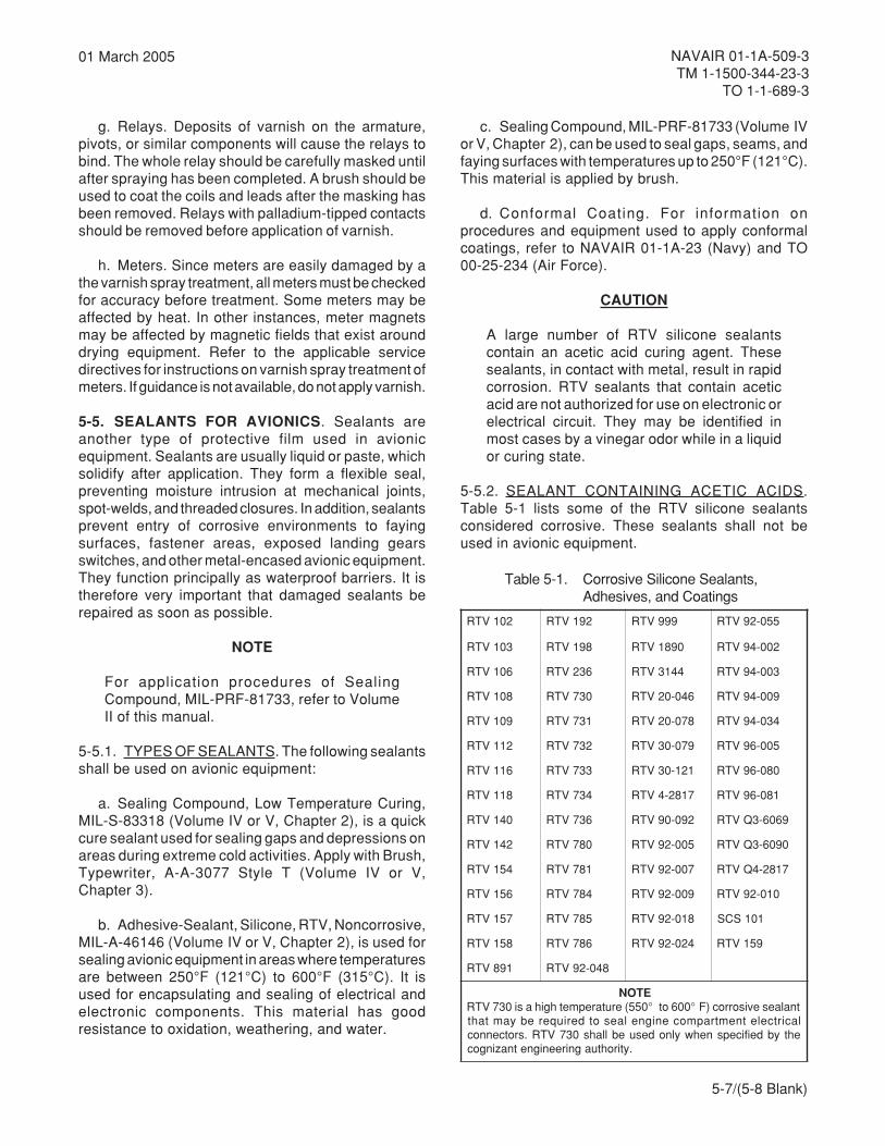
5-7
NAVAIR 01-1A-509-3TM 1-1500-344-23-3
TO 1-1-689-3
01 March 2005
g. Relays. Deposits of varnish on the armature,pivots, or similar components will cause the relays tobind. The whole relay should be carefully masked untilafter spraying has been completed. A brush should beused to coat the coils and leads after the masking hasbeen removed. Relays with palladium-tipped contactsshould be removed before application of varnish.
h. Meters. Since meters are easily damaged by athe varnish spray treatment, all meters must be checkedfor accuracy before treatment. Some meters may beaffected by heat. In other instances, meter magnetsmay be affected by magnetic fields that exist arounddrying equipment. Refer to the applicable servicedirectives for instructions on varnish spray treatment ofmeters. If guidance is not available, do not apply varnish.
5-5. SEALANTS FOR AVIONICS. Sealants areanother type of protective film used in avionicequipment. Sealants are usually liquid or paste, whichsolidify after application. They form a flexible seal,preventing moisture intrusion at mechanical joints,spot-welds, and threaded closures. In addition, sealantsprevent entry of corrosive environments to fayingsurfaces, fastener areas, exposed landing gearsswitches, and other metal-encased avionic equipment.They function principally as waterproof barriers. It istherefore very important that damaged sealants berepaired as soon as possible.
NOTE
For application procedures of SealingCompound, MIL-PRF-81733, refer to VolumeII of this manual.
5-5.1. TYPES OF SEALANTS. The following sealantsshall be used on avionic equipment:
a. Sealing Compound, Low Temperature Curing,MIL-S-83318 (Volume IV or V, Chapter 2), is a quickcure sealant used for sealing gaps and depressions onareas during extreme cold activities. Apply with Brush,Typewriter, A-A-3077 Style T (Volume IV or V,Chapter 3).
b. Adhesive-Sealant, Silicone, RTV, Noncorrosive,MIL-A-46146 (Volume IV or V, Chapter 2), is used forsealing avionic equipment in areas where temperaturesare between 250°F (121°C) to 600°F (315°C). It isused for encapsulating and sealing of electrical andelectronic components. This material has goodresistance to oxidation, weathering, and water.
c. Sealing Compound, MIL-PRF-81733 (Volume IVor V, Chapter 2), can be used to seal gaps, seams, andfaying surfaces with temperatures up to 250°F (121°C).This material is applied by brush.
d. Conformal Coating. For information onprocedures and equipment used to apply conformalcoatings, refer to NAVAIR 01-1A-23 (Navy) and TO00-25-234 (Air Force).
CAUTION
A large number of RTV silicone sealantscontain an acetic acid curing agent. Thesesealants, in contact with metal, result in rapidcorrosion. RTV sealants that contain aceticacid are not authorized for use on electronic orelectrical circuit. They may be identified inmost cases by a vinegar odor while in a liquidor curing state.
5-5.2. SEALANT CONTAINING ACETIC ACIDS.Table 5-1 lists some of the RTV silicone sealantsconsidered corrosive. These sealants shall not beused in avionic equipment.
Table 5-1. Corrosive Silicone Sealants,Adhesives, and Coatings
201VTR 291VTR 999VTR 550-29VTR
301VTR 891VTR 0981VTR 200-49VTR
601VTR 632VTR 4413VTR 300-49VTR
801VTR 037VTR 640-02VTR 900-49VTR
901VTR 137VTR 870-02VTR 430-49VTR
211VTR 237VTR 970-03VTR 500-69VTR
611VTR 337VTR 121-03VTR 080-69VTR
811VTR 437VTR 7182-4VTR 180-69VTR
041VTR 637VTR 290-09VTR 9606-3QVTR
241VTR 087VTR 500-29VTR 0906-3QVTR
451VTR 187VTR 700-29VTR 7182-4QVTR
651VTR 487VTR 900-29VTR 010-29VTR
751VTR 587VTR 810-29VTR 101SCS
851VTR 687VTR 420-29VTR 951VTR
198VTR 840-29VTR
ETONtnalaesevisorroc)F°006ot°055(erutarepmethgihasi037VTRlacirtceletnemtrapmocenignelaesotderiuqerebyamtaht
ehtybdeificepsnehwylnodesuebllahs037VTR.srotcennoc.ytirohtuagnireenignetnazingoc
5-7/(5-8 Blank)

6-1
NAVAIR 01-1A-509-3TM 1-1500-344-23-3
TO 1-1-689-3
01 March 2005
CHAPTER 6TREATMENT OF SPECIFIC AREAS
6-1. GENERAL. All aircraft electrical/electronic unitsmust be opened and inspected for evidence of internalmoisture and corrosion. When corrosion is detected,prompt corrective action is required. This action shallconsist of cleaning, corrosion removal, treatment, andpreservation, where required. Maintenance personnelshould always use the mildest method available toremove corrosion. The procedures and techniques ofcorrosion removal outlined in the following paragraphsare intended to assist avionic technicians in equipmentrepair. In each case, some discretion on the part ofmaintenance personnel is warranted. It is importantthat personnel analyze the problem, select theappropriate corrective action, and confirm corrosioncontrol effectiveness. It is recommended that VolumeI be reviewed for basic information on what avioniccorrosion is, why it occurs, and the various forms it cantake.
6-2. REPAIR OF AVIONIC EQUIPMENT HOUSING,MOUNTING, AND STORAGE HARDWARE.
6-2.1. BILGE AREAS. A common trouble spot on allaircraft is the bilge area, especially in helicopters.These areas contain all types of avionic equipmentand present a natural sump or collection point.Accumulation of waste, hydraulic fluids, water, dirt,loose fasteners, drill shavings and other debris istypical. Liquids shall be pumped or drained from bilgeareas. Bilge areas should be cleaned before equipmentreplacement. All efforts should be made to ensure thatavionic equipment is cleaned and preserved beforebeing returned to these areas. Bilge areas shall becleaned and preserved in accordance with Volume II(Navy and Army) or TO 1-1-691 (Air Force).
6-2.2. EQUIPMENT BAYS. Avionic equipment baysand installed equipment are highly susceptible tocorrosion. This is especially true in helicopters andaircraft using external ram air cooling. The avionicstechnician should routinely survey the inside ofequipment bays whenever he/she is working in theseareas, and report evidence of any corrosion. Theinspection and treatment processes are outlined in thefollowing paragraphs.
NOTE
The use of dissimilar metals in the selection ofscrews, washers, and nuts should beeliminated wherever possible. Refer toparagraph 6-4 for information on bonding andgrounding hardware.
a. Clean and inspect hardware, fixed mountings,and points of metal bonds for signs of galvaniccorrosion. Pay particular attention to areas of dissimilarmetal.
b. Remove corrosion with Abrasive Cloth,ANSI-B 74.18 320 Grit Type I Class I (Volume IV or V,Chapter 2), or Abrasive Mat A-A-58054 Type I(Volume IV or V, Chapter 2).
Compound, Aircraft Cleaning 4MIL-PRF-85570
c. Clean affected areas with a solution of nine partsfresh water to one part Aircraft Cleaning CompoundMIL-PRF-85570 Type II (Volume IV or V, Chapter 2).Apply with Cleaning Cloth CCC-C-46 Class 7(Volume IV or V, Chapter 2).
d. Rinse with fresh water and wipe dry with CleaningCloth CCC-C-46 Class 7 (Volume IV or V, Chapter 2).
Coating, Chemical Conversion 10MIL-DTL-81706
CAUTION
Exercise care when using ChemicalConversion Material, MIL-DTL-81706, nearelectronic hardware. It can cause corrosion ofthe delicate electronic devices if they are notsuitably protected.
e. After corrosion is removed, aluminum surfacesshall be treated with Chemical Conversion Material,
6-2
NAVAIR 01-1A-509-3TM 1-1500-344-23-3TO 1-1-689-3
01 March 2005
MIL-DTL-81706. (Volume IV or V, Chapter 2), andpainted in accordance with Volume II (Navy and Army)and Chapter 5. Air Force personnel should refer toequipment specific manuals for proper color and paintsystems.
Compound, Corrosion Preventive 3Water-DisplacingMIL-C-81309
Compound, Corrosion Preventive 26MIL-DTL-85054
f. When environmental conditions or time do notpermit other surface treatment, preserve with a thinfilm of Water Displacing Corrosion PreventiveCompound, MIL-C-81309 Type II (Volume IV or V,Chapter 2) or Corrosion Preventive Compound,MIL-DTL-85054 Clear (Amlguard) (Volume IV or V,Chapter 2).
6-2.3. ENGINE COMPARTMENTS. Removecorrosion and preserve as follows:
a. Inspect the compartment, hardware, electricalconnectors, terminal boards, junction boxes, and ramair turbine for signs of salt spray contamination andcorrosion.
b. Treat in accordance with paragraph 6-2.2. withthe following exceptions.
(1) Treat electrical connectors in accordancewith paragraphs 6-3.11. through 6-3.11.4.
Compound, Corrosion Preventive 3Water-DisplacingMIL-C-81309
(2) Treat terminal boards in accordance withparagraph 6-2.8. Preserve internal surfaces andterminals with a thin film of Water Displacing CorrosionPreventive Compound, MIL-C-81309 Type III(Volume IV or V, Chapter 2).
(3) Treat ram air turbine in accordance with theapplicable service directives.
6-2.4. BATTERY COMPARTMENTS, BOXES, ANDADJACENT AREAS. The battery, battery cover, batterybox, and adjacent areas (especially areas below thebattery compartment) are subject to the corrosiveaction of the electrolyte. Two different types of batteriesare encountered on avionic equipment, lead acid type(sulfuric acid electrolyte) and nickel-cadmium type(potassium hydroxide electrolyte).
NOTE
Refer to NAVAIR 17-15BAD-1 (Navy) orTM 11-614S203-14-2 (Army) for additionalinformation on maintenance of aircraftbatteries.
6-2.4.1. Preparation of Solutions for Cleaning andNeutralizing Battery Electrolytes. Indicating solutionsare required for cleaning areas subjected to electrolytespills. These solutions determine the location ofcontaminated areas and indicate when these areashave been completely neutralized. Use a 10% sodiumbicarbonate (ordinary baking soda in water) solution toneutralize sulfuric acid from lead acid batteries and a3% boric acid (in water) solution to neutralize potassiumhydroxide from nickelcadmium batteries.
Alcohol, Isopropyl 6TT-I-735
WARNING
Sulfuric acid and battery electrolytes are highlytoxic to eyes, skin, and respiratory tract. Avoidall contact. Skin and eye protection is required.If any acid/ electrolyte contacts the skin oreyes, flood the affected area immediately withwater and consult the Base Medical Service.Emergency shower and eye wash station arerequired. Use only with adequate ventilation.Assure this operation has been reviewed bylocal Bioenvironmental Engineer.
When working around batteries, always weareye protection (face shield), acid resistantrubber apron and gloves.
6-2.4.1.1. Litmus Indicating Solution. Litmus indicatingsolutions are used on lead acid battery electrolytespills. Make one pint of a mixture containing 70%Isopropyl Alcohol, TT-I-735 (Volume IV or V, Chapter 2)

6-3
NAVAIR 01-1A-509-3TM 1-1500-344-23-3
TO 1-1-689-3
01 March 2005
and 30% distilled water, both by volume, and put intoa plastic spray bottle with a hand squeeze pump. Addone tablespoon of litmus powder into the liquid, andmix thoroughly until a deep blue color is observed.Blue litmus paper (Volume IV or V, Chapter 2) mayalso be used as an indicator.
6-2.4.1.2. Bromothymol Blue Indicating Solution.Bromothymol blue indicating solutions are used onnickel-cadmium battery electrolyte spills. To preparesolution, mix 1⁄4 teaspoon of Indicator, BromothymolBlue Reagent (Volume IV or V, Chapter 2) in 3 cups(24 oz.) of deionized or distilled water. Pour one pint ofbromothymol blue solution into a plastic spray bottlewith a hand squeeze pump. Using an eye dropper, addone drop at a time of phosphoric acid, A-A-59282,(Volume IV or V, Chapter 2), into the solution. Mixafter adding each drop, until the color of the solutionchanges from blue to gold/amber.
6-2.4.1.3. Sodium Bicarbonate Neutralizing Solution.Pour one pint of fresh water into a wash bottle, add twoounces (4 tablespoons) of Sodium Bicarbonate, ASTMD 928 (Volume IV or V, Chapter 2) and mix thoroughly.
6-2.4.1.4. Boric Acid Neutralizing Solution. Pour onepint of fresh water into a wash bottle, add one-halfounce (I tablespoon) of Boric Acid, A-A-59282(Volume IV or V, Chapter 2) and mix thoroughly.
6-2.4.2. Cleaning and Neutralizing Procedures.
a. Remove any standing liquid or puddles with asqueeze bulb type syringe, absorbent cloth, or sponges.Place these items in a leak-proof container for removalto prevent the contamination of other areas.
b. Spray the entire suspected area with the properindicator solution, using the minimum amount neededto wet the entire surface. For spills from lead acidbatteries, use the litmus solution, which will change incolor from deep blue to a bright red in areascontaminated by sulfuric acid. For spills fromnickel-cadmium batteries, use the bromothymol bluesolution, which will change in color from amber or goldto a deep blue in areas contaminated by potassiumhydroxide.
c. Apply the correct neutralizing solution (sodiumbicarbonate solution for lead acid batteries, boric acidsolution for nickel-cadmium batteries) to the areas
where the indicating solution has changed color. Ensurethat the area is well saturated and that the stream isdirected into all seams and crevices where electrolytecould collect. Use care to prevent liquids from spreadingto adjacent areas, and ensure that bilge area drainsare open to allow fluids to flow overboard. Allow theneutralizing solution to remain on the surface for atleast 5 minutes or until all bubbling action ceases.
d. Rinse the area thoroughly with a liberal amountof clean water and remove any standing liquid orpuddles, as in paragraph a.
e. Reapply the indicator solution, as in paragraph b.If the solution does not change color, rinse the area, asin paragraph d., and dry the area with clean cloths orrags. If the solution changes color, repeat paragraphs c.and d.
f. Repair damage and apply prepaint treatment,sealant, and coatings as required. Special acid and/oralkali resistant coatings are usually required for batterycompartments, boxes, and areas. Refer to theapplicable aircraft manuals.
6-2.5. FRAMES, MOUNTING RACKS, AND SHOCKMOUNTS. Shock mounts and associated hardware onpod/airframe mounted equipment are usually the lastitems to be inspected for corrosion damage. This isusually because inspection requires the removal of theshock mount to facilitate examination. For this reason,shock mounts and associated metallic hardware mustbe preserved to ensure protection. This does noteliminate the requirement to inspect shock mounts.For frames, mounting racks, and shock mounts thatare not normally painted, remove corrosion andpreserve as follows:
NOTE
The use of dissimilar metals in the selection ofscrews, washers, and nuts should beeliminated, wherever possible. Refer toparagraph 6-4 for information on bonding andgrounding hardware.
a. Remove corrosion with Abrasive Cloth, 320 Grit,ANSI-B74.18 Type I Class I (Volume IV or V,Chapter 2), or Abrasive Mat, A-A-58054 Type I(Volume IV or V, Chapter 2). Pay particular attentionto dissimilar metal couples.
6-4
NAVAIR 01-1A-509-3TM 1-1500-344-23-3TO 1-1-689-3
01 March 2005
Alcohol, Isopropyl 6TT-I-735
b. Clean affected area with one part IsopropylAlcohol, TT-I-735 (Volume IV or V, Chapter 2) mixedwith one part fresh water. Apply with Cleaning Cloth,CCC-C-46 Class 7 (Volume IV or V, Chapter 2). Payparticular attention to shock mounts that contain rubbershock absorbers. These items may swell if immersedin Isopropyl Alcohol, TT-I-735 (Volume IV or V,Chapter 2), for a long period of time. If rubber doesswell, it will return to its normal size after a short periodof time.
Compound, Corrosion Preventive 3Water-DisplacingMIL-C-81309
Compound, Corrosion Preventive 26MIL-DTL-85054
c. Frames, mounting racks, and shock mountassociated metallic hardware shall be preserved witha thin film of Water Displacing Corrosion PreventiveCompound, MIL-C-81309 Type II (Volume IV or V,Chapter 2) or Corrosion Preventive Compound,MIL-DTL-85054, Clear (Amlguard) (Volume IV or V,Chapter 2).
d. For frames, mounting racks, and shock mountsthat are normally painted, remove corrosion and cleanas outlined in paragraphs a. through c. Paint theseareas in accordance with Volume II (Navy). Air Forcepersonnel should refer to equipment specific manualsfor proper color and paint systems. Army personnelshall refer to TM 55-1500-345-23 and TB 43-0118.
6-2.6. EXTERNAL POD MOUNTED EQUIPMENT.External avionic pods are susceptible to the samecorrosive environment as the airframe. Cleaningtechniques are the same with the exception ofelectromagnetic gaskets, shields, electrical connectors,and mating surfaces. Treat as follows:
NOTE
Refer to the applicable service directives forinformation on those areas of external podmounted avionic equipment that may bepreserved without degrading the electricalcharacteristics of the equipment. Do notpreserve water seal gaskets.
Refer to Chapter 7 and the applicable servicedirectives for information on electromagneticgasket plating where the plating surfaces havebeen removed.
a. Remove corrosion and clean in accordance withparagraph 6-2.7.
b. Paint as required by equipment specific manuals.
Compound, Corrosion Preventive 3Water-DisplacingMIL-C-81309
Compound, Corrosion Preventive 26MIL-DTL-85054
c. If painting cannot be accomplished, preserveexternal surfaces with a thin film of Water DisplacingCorrosion Preventive Compound, MIL-C-81309 Type II(Volume IV or V, Chapter 2) or Corrosion PreventiveCompound, MIL-DTL-85054, Clear (Amlguard)(Volume IV or V, Chapter 2).
d. Clean and preserve electrical connectors inaccordance with paragraphs 6-3.11. through 6-3.11.4.
e. Clean and preserve wire harnesses inaccordance with paragraph 6-3.13.
6-2.7. COCKPIT AND CONTROL BOXES. UseVacuum Cleaner, MIL-V-21987 (Volume IV or V,Chapter 3), to vacuum the cockpit area clean. Thefollowing inspection and treatment procedures shallapply to cockpit avionic components.
a. Inspect control box units for corrosion andcontaminants. Pay particular attention to switches,dials, knobs and electrical connectors.
6-5
NAVAIR 01-1A-509-3TM 1-1500-344-23-3
TO 1-1-689-3
01 March 2005
b. Remove corrosion products from metal surfaceswith Abrasive Mat, A-A-58054 Type I (Volume IV or V,Chapter 2), or Cleaning and Polishing Pad,Non-Abrasive (Volume IV or V, Chapter 2) asappropriate.
Solvent, Degreasing 7MIL-PRF-680
c. Clean affected area with Degreasing Solvent,MIL-PRF-680 Type III (Volume IV or V, Chapter 2).Apply with Cleaning Cloth, CCC-C-46 Class 7(Volume IV or V, Chapter 2).
Alcohol, Isopropyl 6TT-I-735
d. Follow with application of one part IsopropylAlcohol, TT-I-735 (Volume IV or V, Chapter 2), to onepart deionized water. Wipe clean with Cleaning Cloth,CCC-C-46 Class 7 (Volume IV or V, Chapter 2).
e. Paint as required by equipment specific manuals.
Compound, Corrosion Preventive 3Water-DisplacingMIL-C-81309
WARNING
Do not use Corrosion Preventive Compounds,MIL-C-81309, MIL-DTL-85054 orMIL-PRF-16173, or Lubricating Oil, GeneralPurpose Preservative, MIL-PRF-32033,around oxygen or oxygen fittings since fire/explosion may result. Corrosion PreventiveCompounds, MIL-C-81309 and MIL-L-87177are flammable and toxic.
CAUTION
Corrosion Preventive Compounds may causecracking or crazing of plastics.
f. Brush or spray Water Displacing CorrosionPreventive Compound, MIL-C-81309 Type II
(Volume IV or V, Chapter 2), on metal surfaces andwipe with cleaning cloth, CCC-C-46 Class 7 (Volume IVor V, Chapter 2). Take steps not to get preservative onplastic faceplate.
g. Clean and preserve toggle, rotary, and pushbuttonswitches in accordance with paragraph 6-3.7.
Detergent, General Purpose 5MlL-D-16791
h. Clean control box faceplates with solution of one(1) ounce (2 tablespoons) Detergent, Liquid, Nonionic,MIL-D-16791 Type I (Volume IV or V, Chapter 2), inone (1) gallon of fresh water. Apply and wipe withFlannel Cloth, CCC-C-458 Type II (Volume IV or V,Chapter 2). Polish glass with clean flannel cloth.
i. Clean and preserve cockpit and control boxelectrical connectors in accordance with paragraphs6-3.11.1. through 6-3.11.4.
6-2.8. TERMINAL BOARDS, JUNCTION BOXES,RELAY BOXES, AND CIRCUIT BREAKER PANELS.Remove covers and access panels. Treat as follows:
WARNING
Ensure that all electrical power is disconnectedfrom the aircraft and all electrical systems inthe aircraft are deactivated. Disconnect allbatteries.
a. External surfaces:
(1) Treat in accordance with paragraph 6-2.2.
(2) Prepare surface and paint in accordancewith Volume II (Navy), TO 1-1-8 (Air Force), and TM55-1500-345-23 and TB 43-0118 (Army).
Compound, Corrosive Preventive 26MIL-DTL-85054
(3) When environmental conditions or time donot permit painting, preserve with a thin film of CorrosionPreventive Compound, MIL-DTL-85054, Clear(Amlguard) (Volume IV or V, Chapter 2).
6-6
NAVAIR 01-1A-509-3TM 1-1500-344-23-3TO 1-1-689-3
01 March 2005
b. Internal Components:
(1) Remove corrosion with Cleaning andPolishing Pad, Non-Abrasive (Volume IV or V,Chapter 2) or Abrasive Mat, A-A-58054 Type I(Volume IV or V, Chapter 2), as appropriate.
Alcohol, Isopropyl 6TT-I-735
(2) Clean affected area with one part IsopropylAlcohol, TT-I-735 (Volume IV or V, Chapter 2), mixedwith one part deionized water. Apply with CleaningCloth, CCC-C-46 Class 7 (Volume IV or V, Chapter 2),Brush, Acid, A-A-289 (Volume IV or V, Chapter 3), orBrush Typewriter, AA-3077 (Volume IV or V,Chapter 3).
(3) Wipe clean and allow to air dry.
(4) Clean and preserve electrical connectorsin accordance with paragraphs 6-3.11. through6-3.11.4.
Compound, Corrosion Preventive 3Water-DisplacingMIL-C-81309
(5) Coat internal surface by applying a thin filmof Water Displacing Corrosion Preventive Compound,Ultra-Thin Film, MIL-C-81309 Type III (Volume IV or V,Chapter 2), to all electrical connections, terminals,and internal surfaces. Avoid the application ofpreservatives on relay and circuit breaker contacts.
6-2.9. METALLIC EQUIPMENT COVERS ANDHOUSINGS. Avionic equipment cases, covers,housings, and associated hardware are usuallyexposed to harsher elements than internal circuitcomponents. As a result, they require more frequentcleaning. Treat any corrosion in accordance withparagraph 6-2.2.
a. Hardware associated with equipment housingsand cases that are not normally painted should bepreserved. Preserve as often as necessary, depending
on the operating environment. Materials andprocedures specified in the appropriate MaintenanceRequirement Cards (MRCs) or Phased MaintenanceInspection Checklist may be used as alternatives.
b. Hinges and latches on equipment covers shallbe preserved in accordance with paragraph 6-2.11.
6-2.10. NONMETALLIC COVERS AND HOUSINGS.In some cases avionic equipment, support equipment,or general purpose test equipment use high impactplastic or fiberglass covers and housings. These shouldbe cleaned as follows:
a. The primary cleaning method shall be cleaningtrack CSR2A or CSR3 (as applicable). Refer toTable 2-3.
b. The Secondary Cleaning Method.
(1) Inspect hardware, hinges and points ofmetal bonds for signs of galvanic corrosion. Payparticular attention to dissimilar metals. Remove anycorrosion with Cloth Abrasive, ANSI-B74.18 Type IClass I (Volume IV or V, Chapter 2), or Abrasive Mat,A-A-5 8054 Type I (Volume IV or V, Chapter 2).
Compound, Aircraft Cleaning 4MIL-PRF-85570
(2) Clean cover and housing with a solution ofnine parts fresh water to one part Aircraft CleaningCompound, MIL-PRF-85570 Type II (Volume IV or V,Chapter 2). Apply with Cleaning Cloth, CCC-C-46Class 7 (Volume IV or V, Chapter 2).
(3) Rinse with fresh water and wipe dry withCleaning Cloth, CCC-C-46 Class 7.
(4) Allow to air dry, if necessary.
(5) Hardware associated with test equipmenthousings and covers that is not normally paintedshould be preserved as often as necessary, dependingon the operating environment. Do not preserve waterseal gaskets.
(6) Equipment hinges and latches shall bepreserved in accordance with paragraph 6-2.11.

6-7
NAVAIR 01-1A-509-3TM 1-1500-344-23-3
TO 1-1-689-3
01 March 2005
6-2.11. EQUIPMENT HINGES AND LATCHES.Inspect hinges and latches on black boxes, accessdoors, covers or housings, for corrosion and conditionof preservatives/ lubricants. Treat as follows:
Solvent, Degreasing 7MIL-PRF-680
a. Clean affected areas with Cleaning Cloth,CCC-C-46 Class 7 (Volume IV or V, Chapter 2)dampened with Degreasing Solvent, MIL-PRF-680Type III.
b. Remove corrosion with Abrasive Mat, A-A-58054Type I Grade A or B (Volume IV or V, Chapter 2) orAbrasive Cloth 320 Grit (Volume IV or V, Chapter 2),as appropriate.
Alcohol, Isopropyl 6TT-I-735
c. Wipe residue with Cleaning Cloth, CCC-C-46Class 7 (Volume IV or V, Chapter 2) dampened withIsopropyl Alcohol, TT-I-735 (Volume IV or V,Chapter 2), and allow to dry.
Coating, Chemical Conversion 10MIL-DTL-81706
CAUTION
Exercise care when using ChemicalConversion Material, MIL-DTL-81706, nearelectronic hardware. It can cause corrosion ofthe delicate electronic devices if they are notsuitably protected.
d. After corrosion is removed, aluminum surfacesshall be treated with Chemical Conversion MaterialMIL-DTL-81706 Class IA (Volume IV or V, Chapter 2),in accordance with Volume II (Navy or Army) or TO1-1-691 (Air Force) and paragraphs 5-3.1.1. and5-3.1.2.
Compound, Corrosion Preventive 26MIL-DTL-85054
e. Prepare bare metal non-moving parts requiringno lubrication in accordance with Volume II (Navy andArmy) or TO 1-1-691 (Air Force). When environmentalconditions or time do not permit, preserve surfacesrequiring no lubrication with a thin film of CorrosionPreventive Compound, MIL-DTL-85054, Clear(Amlguard) (Volume IV or V, Chapter 2).
WARNING
Do not use Corrosion Preventive Compounds,MIL-C-81309, MIL-DTL-85054,MIL-PRF-16173, or Lubricating Oil, GeneralPurpose Preservative, MIL-PRF-32033,around oxygen or oxygen fittings since fire/explosion may result.
Compound, Corrosion Preventive 3Water-DisplacingMIL-C-81309
f. Spray hinges and latches with Water DisplacingCorrosion Preventive Compound, Ultra-Thin Film,MIL-C81309 Type II (Volume IV or V, Chapter 2).
Oil, Lubricating 20General PurposeMIL-PRF-32033
g. Apply Lubricating Oil, General PurposePreservative, MIL-PRF-32033 (Volume IV or V,Chapter 2), on moving parts.
6-2.12. SHELVES, BULKHEADS, AND CREVICES.Inspect shelves, bulkheads, crevices and corners forsigns of corrosion. Examine these areas for deterioratedpaint that is cracked, chipped, or peeled. Treat inaccordance with paragraph 6-2.2.
6-8
NAVAIR 01-1A-509-3TM 1-1500-344-23-3TO 1-1-689-3
01 March 2005
6-2.13. MOISTURE TRAPS AND CAVITY AREAS.Inspect for moisture traps and cavity areas at rear ofequipment shelves. Treat in accordance with paragraph6-2.2.
Sealing Compound 2Corrosion InhibitiveMIL-PRF-81733
a. If necessary, before painting fill depression areasand cavities with Sealing Compound, MIL-PRF-81733(Volume IV or V, Chapter 2).
b. Apply sealing compound and finish in accordancewith Volume II (Navy and Army) or TO 1-1-691/TO1-1-8 (Air Force).
6-2.14. COCKPIT INDICATOR AND MOUNTINGHARDWARE. Inspect cockpit indicator and mountinghardware for dirt, dust, and corrosion. Treat as follows:
a. Remove corrosion and clean in accordance withparagraph 6-2.7.
b. Clean indicator faces in accordance withparagraph 6-2.7.f. Polish glass with clean flannel cloth.
c. Where required, replace decal in accordancewith the applicable service directives.
Compound, Corrosion Preventive 3Water-DisplacingMIL-C-81309
Compound, Corrosion Preventive 26MIL-DTL-85054
d. Apply Water Displacing Corrosion PreventiveCompound, MIL-C-81309 Type II (Volume IV or V,Chapter 2) or Corrosion Preventive Compound,MIL-DTL-85054, Clear (Amlguard) (Volume IV or V,Chapter 2), on mounting hardware.
e. Touch up all bare metal in the cockpit area withthe appropriate coating system.
NOTE
For additional information on bonding andgrounding straps, refer to paragraph 6-4 andthe applicable service directives.
6-2.15. ELECTRICAL BONDING AND GROUNDINGSTRAPS. The bonding and grounding straps used onaircraft and avionic equipment are a major source ofgalvanic corrosion. In most cases, the bonding orgrounding strap is made of a metal that is dissimilar tothe mating surface. This creates a galvanic couple thatin the presence of moisture will corrode rapidly. Treatin accordance with paragraphs 6-5 through 6-5.3.
6-3. REPAIR OF AVIONIC SYSTEMS, EQUIPMENT,AND COMPONENTS.
6-3.1. ANTENNA SYSTEMS. Antenna systems arenormally exposed to fairly severe environments.Without adequate corrosion protection, these systemscan fail via shorts, open circuits, loss of dielectricstrength, signal attenuation, poor bonding, orelectromagnetic interference (EMI). Structural damageto the aircraft can also result. Antennas mounted onthe fuselage require openings in the skin to route thevarious lines to the antenna. The area around theantenna mounting is susceptible to moisture intrusionfrom rain, condensation, aircraft washing, and internalfluids (e.g., fuel, engine oil, or hydraulic fluid) Antennasmounted on the lower fuselage are particularly corrosionprone. The inspection and treatment process areoutlined in the following paragraphs.
NOTE
Instructions on recognizing corrosion areoutlined in Volume I. If corrosion is beyond thesurface stage (i.e. pitting and cracking), referto Volume II (Navy and Army) or TO 1-1-691(Air Force) for assessment/treatmenttechniques.
6-3.1.1. Corrosion Visual Inspection. A visual checkof the antenna mounting base metal surface canreveal signs of corrosion attack. Corrosion depositsare the most obvious indication that an attack hastaken place. Since antennas are usually mounted onaluminum structural materials, corrosion (deposits ofaluminum oxide) generally can be identified as a whiteor greyish-white powder.
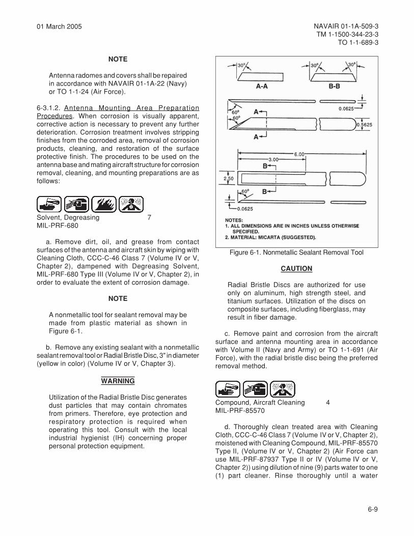
6-9
NAVAIR 01-1A-509-3TM 1-1500-344-23-3
TO 1-1-689-3
01 March 2005
NOTE
Antenna radomes and covers shall be repairedin accordance with NAVAIR 01-1A-22 (Navy)or TO 1-1-24 (Air Force).
6-3.1.2. Antenna Mounting Area PreparationProcedures. When corrosion is visually apparent,corrective action is necessary to prevent any furtherdeterioration. Corrosion treatment involves strippingfinishes from the corroded area, removal of corrosionproducts, cleaning, and restoration of the surfaceprotective finish. The procedures to be used on theantenna base and mating aircraft structure for corrosionremoval, cleaning, and mounting preparations are asfollows:
Solvent, Degreasing 7MIL-PRF-680
a. Remove dirt, oil, and grease from contactsurfaces of the antenna and aircraft skin by wiping withCleaning Cloth, CCC-C-46 Class 7 (Volume IV or V,Chapter 2), dampened with Degreasing Solvent,MIL-PRF-680 Type III (Volume IV or V, Chapter 2), inorder to evaluate the extent of corrosion damage.
NOTE
A nonmetallic tool for sealant removal may bemade from plastic material as shown inFigure 6-1.
b. Remove any existing sealant with a nonmetallicsealant removal tool or Radial Bristle Disc, 3" in diameter(yellow in color) (Volume IV or V, Chapter 3).
WARNING
Utilization of the Radial Bristle Disc generatesdust particles that may contain chromatesfrom primers. Therefore, eye protection andrespiratory protection is required whenoperating this tool. Consult with the localindustrial hygienist (IH) concerning properpersonal protection equipment.
CAUTION
Radial Bristle Discs are authorized for useonly on aluminum, high strength steel, andtitanium surfaces. Utilization of the discs oncomposite surfaces, including fiberglass, mayresult in fiber damage.
c. Remove paint and corrosion from the aircraftsurface and antenna mounting area in accordancewith Volume II (Navy and Army) or TO 1-1-691 (AirForce), with the radial bristle disc being the preferredremoval method.
Compound, Aircraft Cleaning 4MIL-PRF-85570
d. Thoroughly clean treated area with CleaningCloth, CCC-C-46 Class 7 (Volume IV or V, Chapter 2),moistened with Cleaning Compound, MIL-PRF-85570Type II, (Volume IV or V, Chapter 2) (Air Force canuse MIL-PRF-87937 Type II or IV (Volume IV or V,Chapter 2)) using dilution of nine (9) parts water to one(1) part cleaner. Rinse thoroughly until a water
Figure 6-1. Nonmetallic Sealant Removal Tool

6-10
NAVAIR 01-1A-509-3TM 1-1500-344-23-3TO 1-1-689-3
01 March 2005
break-free surface is obtained. Allow to air dry. If waterbreak-free surface is not obtained, reclean area withdilution of four (4) parts water to one (1) part cleaner.Rinse thoroughly to obtain a water break-free surfaceand allow to air dry.
e. Where corrosion products were abrasivelyremoved, apply Chemical Conversion Coating,MIL-DTL-81706 Class 3 to the affected surfaces. TheAlodine Touch 'N Prep Pen (Volume IV or V, Chapter 2)is the preferred treatment method. If the Touch 'N PrepPen is used, only one coat should be applied and thetreated surface does not require rinsing or wiping offand can be air or forced air dried. Allow coated surfacesto dry before proceeding. See Volume II and Chapter 5for chemical conversion material procedures.
f. (N)(A) Apply appropriate primer and topcoat tothe exposed bare metal surrounding the antenna andextending 3/16" under the outer edge of the antennafootprint. This coating will provide added corrosionprotection to the perimeter of the antenna base if thegasket or perimeter seal deteriorates over time.Figure 6-2 shows paint line after application of primerand topcoat.
g. (AF) Inspect the area to ensure there is no baremetal extending beyond the outer edge of the antennamounting surface and extending 3/16" inward from theouter edge of the antenna footprint. If bare metal existsin this area, apply appropriate primer before attachingthe antenna. This primer will provide added corrosionprotection to the aircraft structure at the perimeter ofthe antenna should there be any misalignments or
miscuts of the gasket. Primer may be applied with aSempen, brush, small roller, or other approvedapplication process. Refer to weapon system specificTO or TO 1-1-8 for primer selection and applicationprocesses.
NOTE
(Navy) AVDEC gasket installation requiresauthorization from the cognizant type/model/series engineering authority for the aircraft.
6-3.1.3. Antenna Mounting (Air Force PreferredMethod). These procedures are applicable to all rigid,flush, and dome antennas except in accordance withaircraft specific technical manuals. Even though themounting bases of antennas vary in shape and size,the following installation procedures are typical andshall be used on all antennas allowing the use of agasket.
a. Prepare aircraft corresponding mating surface(skin) and antenna mounting surface (area) inaccordance with section 6-3.1.2, paragraphs a.through g.
b. Remove conductive gasket from the protectivepackaging. Exercise caution not to fold or bend thematerial. Verify that fastener holes and connectorcutouts in the gasket will align with the antenna mountwhen positioned for installation. Remove release filmonly from the side of the gasket marked "antenna side"and position over the antenna base. Beginning at oneside or the corner of the antenna, place gasket intoposition, carefully aligning gasket fastener holes withantenna base fastener holes. Release film shouldremain on exposed "aircraft side" of gasket untilimmediately prior to antenna installation to the aircraftsurface. Figure 6-3 shows removal of the release filmsprior to installation on the aircraft.
CAUTION
Do not open the sealant material package untilit is ready for use. Follow the manufacturer’sinstructions on the application syringe forpriming and mixing. Discard the syringe if ithas been removed from the package for morethan 24 hours, as sealant performance may becompromised.
c. If antennas are located in areas where oil, grease,or fuel could pool near antenna connectors (normally
Figure 6-2. Paint Line After Application ofPrimer and Topcoat

6-11
NAVAIR 01-1A-509-3TM 1-1500-344-23-3
TO 1-1-689-3
01 March 2005
on the underside of the aircraft), the connector basesshould be sealed with Self-Leveling Green Sealant(Volume IV or V, Chapter 2) in accordance with thefollowing procedure.
(1) To keep antenna level, use a locallyfabricated holding fixture. This can be made from thebottom of a cardboard box.
(2) Insert the antenna through the hole in theholding fixture.
(3) Ambient temperature shall be a minimumof 50°F prior to priming, mixing and applyingSelf-Leveling Green Sealant (Volume IV or V,Chapter 2). Apply sealant around the base of theantenna connector(s) until level with the conductivegasket, and allow the sealant to cure for 30 minutes.Figure 6-4 shows application of the self-leveling greensealant.
d. Clean and prepare aircraft antenna connectorsand cables in accordance with section 6-3.11.
e. Mate connectors/cables in accordance with theapplicable aircraft TO/MIM/TM and apply corrosionprotective materials. For antenna connectors/cables,the preferred method of protection against corrosion isto seal mated connectors using Stretch Seal ConnectorTape (Volume IV or V, Chapter 2). The stretch sealconnector tape cannot be used if the aircraft cutouthole is not at least 1⁄4 inch greater in diameter than theconnector diameter. A tight wrap is necessary to ensurea proper seal. To apply stretch seal to antennaconnectors/cables, begin at the base of the antennaconnector and, removing release film as necessary,wrap the wet side of the tape around the matedconnector with a 50% overlap while stretching therelease tape 25% to 50% ensuring a tight wrap.Coverage shall be from the base of the antennaconnector to at least 1⁄2 inch beyond the connector andonto the insulation jacket of the coaxial cable. Applycable spot tie or string tie immediately above andbelow the mated connector to secure the free ends ofthe tape to ensure it does not unravel. Figure 6-5shows the finished application of the stretch sealprotective wrap. If connector wraps are not availableor inappropriate, apply a film of Water DisplacingCorrosion Preventive Compound, MIL-C-81309 TypeIII (Volume IV or V, Chapter 2) (Air Force can useMIL-L-87177 Grade B as an alternate) to the shell orexterior of the mated connector.
Figure 6-3. Removal of Release Film From Gasket
Figure 6-4. Application of Self-Leveling Green Sealant
Figure 6-5. Stretch Seal Protective Wrap Applied toAntenna Connector
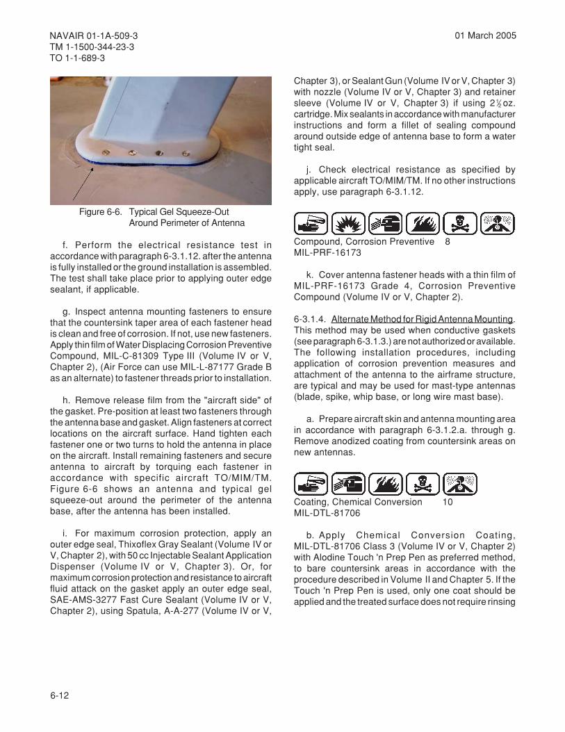
6-12
NAVAIR 01-1A-509-3TM 1-1500-344-23-3TO 1-1-689-3
01 March 2005
f. Perform the electrical resistance test inaccordance with paragraph 6-3.1.12. after the antennais fully installed or the ground installation is assembled.The test shall take place prior to applying outer edgesealant, if applicable.
g. Inspect antenna mounting fasteners to ensurethat the countersink taper area of each fastener headis clean and free of corrosion. If not, use new fasteners.Apply thin film of Water Displacing Corrosion PreventiveCompound, MIL-C-81309 Type III (Volume IV or V,Chapter 2), (Air Force can use MIL-L-87177 Grade Bas an alternate) to fastener threads prior to installation.
h. Remove release film from the "aircraft side" ofthe gasket. Pre-position at least two fasteners throughthe antenna base and gasket. Align fasteners at correctlocations on the aircraft surface. Hand tighten eachfastener one or two turns to hold the antenna in placeon the aircraft. Install remaining fasteners and secureantenna to aircraft by torquing each fastener inaccordance with specific aircraft TO/MIM/TM.Figure 6-6 shows an antenna and typical gelsqueeze-out around the perimeter of the antennabase, after the antenna has been installed.
i. For maximum corrosion protection, apply anouter edge seal, Thixoflex Gray Sealant (Volume IV orV, Chapter 2), with 50 cc Injectable Sealant ApplicationDispenser (Volume IV or V, Chapter 3). Or, formaximum corrosion protection and resistance to aircraftfluid attack on the gasket apply an outer edge seal,SAE-AMS-3277 Fast Cure Sealant (Volume IV or V,Chapter 2), using Spatula, A-A-277 (Volume IV or V,
Chapter 3), or Sealant Gun (Volume IV or V, Chapter 3)with nozzle (Volume IV or V, Chapter 3) and retainersleeve (Volume IV or V, Chapter 3) if using 21⁄2 oz.cartridge. Mix sealants in accordance with manufacturerinstructions and form a fillet of sealing compoundaround outside edge of antenna base to form a watertight seal.
j. Check electrical resistance as specified byapplicable aircraft TO/MIM/TM. If no other instructionsapply, use paragraph 6-3.1.12.
Compound, Corrosion Preventive 8MIL-PRF-16173
k. Cover antenna fastener heads with a thin film ofMIL-PRF-16173 Grade 4, Corrosion PreventiveCompound (Volume IV or V, Chapter 2).
6-3.1.4. Alternate Method for Rigid Antenna Mounting.This method may be used when conductive gaskets(see paragraph 6-3.1.3.) are not authorized or available.The following installation procedures, includingapplication of corrosion prevention measures andattachment of the antenna to the airframe structure,are typical and may be used for mast-type antennas(blade, spike, whip base, or long wire mast base).
a. Prepare aircraft skin and antenna mounting areain accordance with paragraph 6-3.1.2.a. through g.Remove anodized coating from countersink areas onnew antennas.
Coating, Chemical Conversion 10MIL-DTL-81706
b. Apply Chemical Conversion Coating,MIL-DTL-81706 Class 3 (Volume IV or V, Chapter 2)with Alodine Touch 'n Prep Pen as preferred method,to bare countersink areas in accordance with theprocedure described in Volume II and Chapter 5. If theTouch 'n Prep Pen is used, only one coat should beapplied and the treated surface does not require rinsing
Figure 6-6. Typical Gel Squeeze-OutAround Perimeter of Antenna

6-13
NAVAIR 01-1A-509-3TM 1-1500-344-23-3
TO 1-1-689-3
01 March 2005
or wiping off and can be air or forced air dried. Allowcoated surfaces to dry before proceeding.
Compound, Corrosion Preventive 8MIL-PRF-16173
c. Apply an even coating of Corrosion PreventiveCompound, MIL-PRF-16173 Grade 4 (Volume IV or V,Chapter 2) to both the aircraft skin surface and antennamast base. Avoid getting the material in the basecountersink areas. Wipe any Corrosion PreventiveCompound from the conversion coated countersinkusing a Cleaning Cloth, CCC-C-46 Class 7 (Volume IVor V, Chapter 2) dampened with water and CleaningCompound, MIL-PRF-85570 Type II, (Volume IV or V,Chapter 2) and allow to air dry. Air Force can useCleaning Compound, MIL-PRF-87937 Type II or IV(Volume IV or V, Chapter 2).
d. Position the antenna base. Ensure countersinkarea is clean under fastener heads. Install antennaand torque fasteners in accordance with specific aircraftmaintenance manuals.
e. Check electrical resistance in accordance withaccordance with applicable aircraft TO/MIM/TM. If noother instructions apply, use paragraph 6-3.1.12.
Alcohol, Isopropyl 6TT-I-735
f. Clean the outside edge of the antenna attachmentarea and fastener heads with a Cleaning Cloth,CCC-C-46 Class 7 (Volume IV or V, Chapter 2),moistened with Isopropyl Alcohol, TT-I-735 (Volume IVor V, Chapter 2) and allow to air dry.
Sealing Compound 2Corrosion InhibitiveMIL-PRF-81733
g. Using Spatula, A-A-277 (Volume IV or V,Chapter 3) or Sealant Gun (Volume IV or V, Chapter 3)with Nozzle (Volume IV or V, Chapter 3) and RetainerSleeve (Volume IV or V, Chapter 3) if using 21⁄2 oz.sealant cartridge, form a fillet of Sealing Compound,
MIL-PRF-81733 (Volume IV or V, Chapter 2) aroundthe outside edge of the antenna/mast base to form awater tight seal.
Compound, Corrosion Preventive 8MIL-PRF-16173
h. Cover fastener heads with Corrosion PreventiveCompound, MIL-PRF-16173 Grade 4 (Volume IV or V,Chapter 2).
i. Allow sealant to cure for 30 minutes, then removeexcess sealant from aircraft skin using a nonmetallicscraper shown in Figure 6-1.
6-3.1.5. Alternate Method for Flush or Dome AntennaMounting. This method is to be used when conductivegaskets (see paragraph 6-3.1.3.) are not available, orwhen not permitted by aircraft specific technical manual.These antennas usually are installed on aircraft aspart of the primary structure. The radiating elements ofthe antenna and fiberglass cover are normally individualunits. The procedures for protecting these antennasare:
NOTE
Antenna cover damage shall be repaired inaccordance with NAVAIR 01-1A-22 (Navy)and TO 1-1-24 (Air Force).
a. Clean and remove corrosion from the antennainstallation areas in accordance with paragraph6-3.1.2.a.-g.
Compound, Corrosion Preventive 3Water-DisplacingMIL-C-81309
b. Install antenna in accordance with the applicableservice directives. Prior to attaching dome or cover,spray a coating of Water Displacing CorrosionPreventive Compound, MIL-C-81309 Type III(Volume IV or V, Chapter 2), on the internal areas ofthe connector. Mate the connector and apply WaterDisplacing, Corrosion Preventive Compound,MIL-C-81309 Type II (Volume IV or V, Chapter 2),over the antenna mounts, the outside of the mated

6-14
NAVAIR 01-1A-509-3TM 1-1500-344-23-3TO 1-1-689-3
01 March 2005
antenna connectors, and all other exposed metallichardware, including anchor nuts, and nut plates.
Sealing Compound 2Corrosion InhibitiveMIL-PRF-81733
c. Install dome or cover. With Spatula, A-A-277(Volume IV or V, Chapter 3), apply a uniform coatingof Sealing Compound, MIL-PRF-81733 (Volume IV orV, Chapter 2), over the junction of fiberglass cover andaircraft skin. Ensure sealant also covers fastener headsto form a watertight seal.
NOTE
For antennas with EMI gaskets, place sealantaround the outer edge (periphery) of the gasketto prevent the entry of moisture. Ensure nosealant gets between the conductive EMIgasket and the contacting skin, since thesealant is an insulator.
d. Allow the sealant to cure for one-half hour, thenremove excess sealant from the aircraft skin areaaround the antenna using a nonmetallic scraper shownin Figure 6-1.
6-3.1.6. Radar Dish Antenna Corrosion PreventiveProcedure. One of the primary problems related todish antennas is that the protective finish on the dishis subject to scratching and chipping. This usuallyoccurs in the process of normal handling andmaintenance. The antenna metal is usually aluminumor magnesium. Since both metals are anodic to theattaching hardware, the dish is potentially subject togalvanic corrosion around the hardware. In addition,the antenna is subject to surface corrosion whereverthe finish is damaged. Depending upon facilities,deployment, and other factors, either refinishing or atemporary protection procedure is appropriate. Referto Volume II (Navy or Army) or TO 1-1-691/TO 1-1-8(Air Force) for procedures for stripping, cleaning, andrefinishing. Refinishing is normally justified only in thecase of general finish damage (at least 20% of theantenna area).
CAUTION
There are some radar antennas that have aprotective finish or covering, such as mylar,placed over the aluminum/magnesium basemetal. Refer to the applicable service directivesfor further information and repair procedureson these antennas.
6-3.1.7. Temporary Radar Dish Antenna Protection.This procedure is appropriate for repair of limiteddamage to the finish of a dish antenna. It is alsoappropriate for touch-up type use. Organizational/Unitor Intermediate level activities shall perform thefollowing procedure:
a. Remove surface corrosion with Abrasive Mat,A-A-58054 Type I (Volume IV or V, Chapter 2).
Alcohol, Isopropyl 6TT-I-735
b. After completion of corrosion removal, clean thearea with Isopropyl Alcohol, TT-I-735 (Volume IV or V,Chapter 2). Apply by wiping area with solventdampened Cleaning Cloth, CCC-C-46 Class 7(Volume IV or V, Chapter 2), or spray application.
c. Allow to air dry.
Compound, Corrosive Preventive 26MIL-DTL-85054
d. Spray a coating of Water Displacing, CorrosionPreventive Compound, MIL-DTL-85054, Clear(Amlguard) (Volume IV or V, Chapter 2), over theaffected areas. Unless the repaired area is subject tosignificant abrasion or erosion, this coating will providerelatively long term corrosion protection (at least oneyear).
6-3.1.8. Radar Antenna Associated Hardware. Forprotection of the radar antenna associated hardware,such as nuts, bolts, screws and washers, utilize thefollowing procedure:
6-15
NAVAIR 01-1A-509-3TM 1-1500-344-23-3
TO 1-1-689-3
01 March 2005
Alcohol, Isopropyl 6TT-I-735
NOTE
Replace nuts, bolts, screws and washers whichhave the protective coating (normally cadmium)worn off. Refer to the applicable servicedirectives for information on replacement parts.
a. Clean hardware with Isopropyl Alcohol, TT-I-735(Volume IV or V, Chapter 2), using a Cleaning Cloth,CCC-C-46 Class 7 (Volume IV or V, Chapter 2).
b. Allow to air dry.
c. If corrosion is present but replacement is notpractical, surface corrosion on hardware may beremoved with an Abrasive Mat, A-A-58054 Type I(Volume IV or V, Chapter 2). Repeat paragraphs a.and b. after corrosion removal.
Compound, Corrosion Preventive 3Water DisplacingMIL-C-81309
d. Spray a coating of Water Displacing, CorrosionPreventive Compound, MIL-C-81309 Type II(Volume IV or V, Chapter 2), over cleaned hardwareafter installation.
6-3.1.9. Antenna Connectors. Antenna connectorsrequire special procedures to avoid moisture entry andcorrosion damage. Corrosion is, by far, the principalcause of antenna performance deterioration. Cleanand preserve antenna connectors, both multi-pin andcoaxial, in accordance with paragraphs 6-3.11. through6-3.11.4.
6-3.1.10. UHF/VHF/ADF Antenna Sealing. Thelocation of UHF/VHF/ADF antennas is normally on thelower fuselage. This results in a particularly severecorrosion problem due to fluids in the bilge area. Thishas been the principal cause of maintenancerequirements on these antennas. The following
preventive procedures shall be utilized to minimizethis problem.
Solvent, Degreasing 7MIL-PRF-680
a. With antenna removed, clean grease, oil, anddirt from aircraft mounting areas with Cleaning Cloth,CCC-C-46 Class 7 (Volume IV or V, Chapter 2),dampened with Degreasing Solvent, MIL-PRF-680Type III (Volume IV or V, Chapter 2).
NOTE
For corrosion beyond the surface stage, referto Volume II (Navy and Army) or TO 1-1-691(Air Force).
b. Remove any surface corrosion present withAbrasive Mat, A-A-58054 (Volume IV or V, Chapter 2)or Abrasive Cloth, 320 Grit, ANSI-B74.18 (Volume IVor V, Chapter 2).
Alcohol, Isopropyl 6TT-I-735
c. Wipe clean the corrosion products from theantenna and aircraft mounting areas with a CleaningCloth, CCC-C-46 Class 7 (Volume IV or V, Chapter 2),dampened with Isopropyl Alcohol, TT-I-735 (Volume IVor V, Chapter 2).
d. Allow to air dry.
e. Normally the antenna is assembled with the dustcover mated to the bottom of the antenna casting. Theantenna cavity is installed inside the casting. A plate,called an antenna element, mates to the antennacavity flange under a plastic plate. During assembly ofthe antenna components, discard the extruded rubberdust cover channel which fits between the dust coveredge and the antenna casting. Clean the circumferenceof the mated dust cover and antenna casting by wipingwith a Cleaning Cloth, CCC-C-46 Class 7 (Volume IVor V, Chapter 2) dampened with Isopropyl AlcoholTT-I-735 (Volume IV or V, Chapter 2). Similarly, cleanaround the circumference of the plastic plate whichmates to the antenna cavity, and the top of the fastenerson the dust cover.
6-16
NAVAIR 01-1A-509-3TM 1-1500-344-23-3TO 1-1-689-3
01 March 2005
Sealing Compound 2Corrosion InhibitiveMIL-PRF-81733
f. Seal the junction of dust cover, antenna cavityand casting outer edge with Sealing Compound,MIL-PRF-81733 (Volume IV or V, Chapter 2), appliedwith Spatula, AA-277 (Volume IV or V, Chapter 3), orSealant Gun (Volume IV or V, Chapter 3) with Nozzle(Volume IV or V, Chapter 3). Seal aroundcircumference of the plastic plate, antenna cavity, andtop of the fasteners on the dust cover.
Compound, Corrosion Preventive 3Water-DisplacingMIL-C-81309
g. After sealant has cured for one-half hour, installantenna and spray a coating of Water DisplacingCorrosion Preventive Compound, MIL-C-81309 Type II(Volume IV or V, Chapter 2), over the antenna mounts.
h. Clean and preserve electrical connectors inaccordance with paragraphs 6-3.11. through 6-3.11.4.
Sealing Compound 2Corrosion InhibitiveMIL-PRF-81733
i. Seal the circumference of the antenna and aircraftmating surface with Sealing Compound,MIL-PRF-81733 (Volume IV or V, Chapter 2), appliedwith brush, spatula or sealant gun in accordance withparagraph f.
6-3.1.11. Long Wire/Direction Finder (DF) SenseAntenna Corrosion Prevention Procedures. Thecleaning and preservation procedures for this type ofantenna are as follows:
a. The corrosion removal and cleaning proceduresprior to mounting the antenna mast are described inparagraph 6-3.1.2.
NOTE
If more than surface corrosion is present (forexample, pitting), the part should be replaced.
b. Preparation of individual parts involves removalof surface corrosion on the antenna mast, cableshackle, and clevis bolts, using an Abrasive Mat,A-A-58054 Type I (Volume IV or V, Chapter 2).
Alcohol, Isopropyl 6TT-I-735
c. Clean dirt, oil, grease, and any residue by wipingthe parts with a Cleaning Cloth, CCC-C-46 Class 7(Volume IV or V, Chapter 2), dampened with IsopropylAlcohol, TT-I-73 5 (Volume IV or V, Chapter 2).
d. Allow to air dry.
e. Assemble parts and install long wire/DF antennaby referring to the applicable service directives forattachment and tensioning instructions.
Compound, Corrosion Preventive 3Water-DisplacingMIL-C-81309
NOTE
It is preferable to apply Water Displacing,Corrosion Preventive Compound,MIL-C-81309 Type II, to new bare wire afterthe antenna is installed/tensioned. If access tothe wire after installation makes this impractical,wet wiping the wire with MIL-C-81309 Type IIcan be performed prior to installation. In sucha case, attempt to minimize flexing, coiling orabrasion of the wire after the MIL-C-81309Type II is applied and before the wire isinstalled/tensioned.
f. With the antenna installed, spray a coating ofWater Displacing, Corrosion Preventive Compound,MIL-C-81309 Type II (Volume IV or V, Chapter 2),over the attaching hardware. If a new bare wire (nonylon sleeving) has been installed, wipe wire with aCleaning Cloth, CCC-C-46 Class 7 (Volume IV or V,
6-17
NAVAIR 01-1A-509-3TM 1-1500-344-23-3
TO 1-1-689-3
01 March 2005
Chapter 2), soaked with the Water Displacing,Corrosion Preventive Compound, MIL-C-81309 Type II,so the fluid can penetrate around the individual strands.
g. To prevent moisture from entering the insulator,fill the space around the wire where it enters theinsulator with Room Temperature Vulcanizing,Adhesive Sealant, RTV 3140, Clear, MIL-A-46146(Volume IV or V, Chapter 2). Seal both ends of theinsulator in this manner.
6-3.1.12. Antenna Bonding/Grounding ConnectionElectrical Resistance Test. The electrical resistancetest is performed after an antenna base is mounted orground installation is assembled. The test shall takeplace prior to applying sealant, if applicable. Propertorquing of connections , good resistance readings,and complete sealing are all essential to ensure aconnection will function reliably in field service.
CAUTION
It is essential that the probe be placed againstbare metal when taking the reading. Therotating probe tips will create bare metal contactwhen pressed into the surface.
6-3.1.12.1. Using a milliohm meter, such as the R1-LEmilliohm meter, conduct an electrical resistance-bondingtest to measure resistance between antenna/equipmentbase and the aircraft structure. Select a scale on themilliohmmeter such that the maximum allowable reading(2.5 millohms) is near mid-range. This will to ensuremaximum instrument accuracy.
6-3.1.12.2. The resistance between the antenna base/equipment to be grounded and aircraft structure shallnot exceed 2.5 milliohms.
6-3.2. AVIONIC TEST EQUIPMENT. Precisionmeasurement/ test equipment is required for testing,troubleshooting, and repairing modern avionic systems.This makes the reliability of these test systems in anyenvironment critical for aircraft flight and missionessential functions. Aircraft operational requirementsoften result in short turnaround repair times fordamaged/malfunctioning avionic equipment. Thisprovides the avionic technician litt le time totroubleshoot, test, and repair an avionic system.Valuable maintenance time is lost if test equipment isnot functioning properly. A major source of equipmentmalfunction is due to corrosion. The corrosion sourcesthat are particularly detrimental to avionic testequipment include:
a. Moisture and fluid intrusion (rain, condensationfuel, or hydraulic fluid).
b. Corrosive elements in the surroundingatmosphere.
c. Malfunctioning or inadequate shopenvironmental control systems.
d. Malfunctioning or inadequate built-in filtersystems.
NOTE
In this section, use of the term "avionic testequipment" shall refer to all aircraft electricaland electronic system test equipment. Thisincludes support equipment, oscilloscopes,signal generators, meters, automatic testequipment (ATE), or any equipment used toperform measurements, test, or troubleshootavionic systems.
6-3.2.1. Cleaning Versus Calibration. A problemcommon to all automatic/manual test equipment is theeffects dirt, dust, and lint have on equipment calibration.Most test equipment, particularly older units, has notbeen cleaned periodically. This allows contaminantsto collect on components and become an integral partof the circuit, altering circuit parameters. For example,a small amount of dust around a vacuum tube socketcan affect circuit parameters. Thesecontaminantinduced changes are compensated forduring each recalibration process and can limit theequipment’s peak operating efficiency over time. Also,it is easy for calibration of equipment to shift in servicewhen some of the contaminants are dislodged. Becauseof the effect that contaminants can have on electricalcharacteristics, it is common for cleaning to significantlyaffect the electrical performance. Cleaning (andpreservation) is mandatory immediately afterequipment exposure to any of the following conditions:
a. External exposure to wet weather conditions.
b. Internal exposure to water or any other fluid.
c. Internal or external exposure to fire extinguishingagents.
d. Internal exposure to electrolyte or corrosivedeposits from batteries.
6-18
NAVAIR 01-1A-509-3TM 1-1500-344-23-3TO 1-1-689-3
01 March 2005
6-3.2.2. Support Equipment/General Purpose TestEquipment Covers and Housings. The cleaning,corrosion removal, and preservation of supportequipment/general purpose test equipment housingsand covers shall be as follows:
NOTE
Prior to cleaning the covers and housings,remove the operator’s panel, electrical/electronic components, harnesses, andconnectors.
a. Primary Method.
(1) Remove corrosion and clean in accordancewith cleaning track BCSR2A5 or BCSR35, asapplicable. Refer to Table 2-3.
(2) Remove oil, grease and hydraulic fluid inaccordance with cleaning track DBSR2A5 or DBSR35,as applicable. Refer to Table 2-3.
(3) If no corrosion products, oil, grease, orhydraulic fluid exists, clean in accordance with cleaningtrack CSR2A5 or CSR35, as applicable. Refer toTable 2-3.
b. The secondary method shall be in accordancewith paragraph 6-2.2.
c. Prepare surfaces and paint in accordance withChapter 5 and Volume II.
Compound, Corrosion Preventive 3Water-DisplacingMIL-C-81309
d. If painting is not practical, temporarily preserveunpainted surfaces with a thin coating of WaterDisplacing Corrosion Preventive Compound,MIL-C-81309 Type II (Volume IV or V, Chapter 2).
e. Hardware associated with test equipmenthousings and covers that are not normally paintedshould be preserved as often as necessary, dependingon the operating environment.
f. Equipment cover hinges and latches shall bepreserved in accordance with paragraph 6-2.11.
6-3.2.3. ATE Cabinets, Doors and Panels. Cleaning,corrosion removal, and preservation of ATE cabinets,doors, and panels shall be as follows:
NOTE
The use of dissimilar metals in the selection ofscrews, washers and nuts should be eliminatedwherever possible. Refer to paragraph 6-4and NAVAIR 01-1A-505, NAVAIR 01-1A-1(Navy); TO 1-1A-14, TO 1-1A-8 (Air Force); orTM 55-1500-323-24 (Army) for information onbonding/grounding hardware.
a. Inspect hardware and points of metal bonds forsigns of galvanic corrosion. Pay particular attention todissimilar metals.
b. Remove any corrosion with Cloth Abrasive,ANSI-B74.18 Type I Class I (Volume IV or V,Chapter 2), or Abrasive Mat, A-A-58054 Type I(Volume IV or V, Chapter 2).
Compound, Aircraft Cleaning 4MIL-PRF-85570
c. Clean affected areas with a solution of nine (9)parts fresh water to one (1) part Aircraft CleaningCompound, MIL-PRF-85570 Type II (Volume IV or V,Chapter 2). Apply with Cleaning Cloth, CCC-C-46Class 7 (Volume IV or V, Chapter 2).
d. Rinse with fresh water and wipe dry with CleaningCloth, CCC-C-46 Class 7.
e. If required, aluminum surfaces shall be treatedwith chemical conversion material in accordance withChapter 5 and Volume II.
f. Prepare surface and paint in accordance withChapter 5 and Volume II.
Compound, Corrosion Preventive 26MIL-DTL-85054
g. If painting is not practical, temporarily preserveunpainted surfaces with a thin coating of CorrosionPreventive Compound, MIL-DTL-85054, Clear(Amlguard) (Volume IV or V, Chapter 2).

6-19
NAVAIR 01-1A-509-3TM 1-1500-344-23-3
TO 1-1-689-3
01 March 2005
h. Hardware associated with test equipmenthousing and covers that are not normally paintedshould be preserved as often as necessary, dependingon the operating environment. Do not preserve waterseal gaskets.
i. Equipment covers, hinges and latches shall bepreserved in accordance with paragraph 6-2.11.
6-3.2.4. Battery Compartments. Some supportequipment and general purpose test equipment containinternal batteries. Clean, neutralize, and preserve thebattery compartment as follows:
a. Clean and neutralize electrolyte spills inaccordance with paragraphs 6-2.4.1. through 6-2.4.2.as applicable.
b. Prepare surface and paint in accordance withChapter 5 and Volume II.
Compound, Corrosion Preventive 3Water-DisplacingMIL-C-81309
c. If painting is not practical, temporarily preservethe cleaned battery compartment with a thin coating ofWater Displacing Corrosion Preventive Compound,MIL-C-81309 Type II (Volume IV or V, Chapter 2).
6-3.2.5. Meters. Voltmeters, ammeters, andmultimeters are usually constructed of high impactplastic or acrylic. Normally these meters are notdisassembled for cleaning. Clean as follows:
Alcohol, Isopropyl 6TT-I-735
a. Clean metal hardware and metal surfaces withan application of one part Isopropyl Alcohol, TT-I-735(Volume IV or V, Chapter 2) to one part fresh water.Wipe clean with Cleaning Cloth, CCC-C-46 Class 7(Volume IV or V, Chapter 2).
Compound, Corrosion Preventive 3Water-DisplacingMIL-C-81309
b. Apply Water Displacing Corrosion PreventiveCompound, MIL-C-81309 Type II (Volume IV or V,Chapter 2), on metal hardware. Take steps not to getpreservative on acrylic plastic faceplates.
c. Clean toggle, rotary and push button switches inaccordance with paragraph 6-3.7.
d. Clean meter faceplates in accordance withparagraph 6-2.7.h.
Detergent, General Purpose 7MlL-D-16791
e. Clean high impact plastic or acrylic housingswith solution of one ounce (2 tablespoons) Detergent,Liquid Nonionic, MIL-D-16791 Type I (Volume IV or V,Chapter 2) in one (1) gallon of fresh water. Apply andrub surface clean using Cleaning Cloth, CCC-C-46Class 7 (Volume IV or V, Chapter 2), that is wet withcleaning solution. When surfaces are clean, removecleaner residue by wiping with a clean Cleaning Cloth,CCC-C-46 Class 7, that has been frequently rinsedand kept damp with clean water.
6-3.2.6. Operator and Instrument Panels. Generalpurpose test equipment, support equipment, and ATEoperator/instrument panels shall be cleaned externallyand preserved as follows:
a. Inspect operator and instrument panels forcorrosion and contaminants. Pay particular attentionto switches, dials, knobs, and hardware.
b. Remove any corrosion from metal surfaces withAbrasive Mat, A-A-58054 Type I (Volume IV or V,Chapter 2), or Cleaning and Polishing Pad,Non-Abrasive (Volume IV or V, Chapter 2).

6-20
NAVAIR 01-1A-509-3TM 1-1500-344-23-3TO 1-1-689-3
01 March 2005
Alcohol, Isopropyl 6TT-I-735
c. Clean metal surfaces with one part IsopropylAlcohol, TT-I-735 (Volume IV or V, Chapter 2) to onepart fresh water. Apply with Cleaning Cloth, CCC-C-46Class 7 (Volume IV or V, Chapter 2).
Compound, Corrosion Preventive 3Water DisplacingMIL-C-81309
d. Apply Water Displacing Corrosion PreventiveCompound, MIL-C-81309 Type II (Volume IV or V,Chapter 2) on metal hardware. Take steps not to getpreservative on acrylic plastic faceplates.
e. If required, aluminum surfaces shall be treatedwith Chemical Conversion Material, in accordancewith Chapter 5 and Volume II.
f. Prepare surface and paint in accordance withChapter 5 and Volume II.
g. Clean and preserve toggle, rotary and pushbuttonswitches in accordance with paragraph 6-3.7.
h. Clean operator/ instrument faceplate inaccordance with paragraph 6-2.7.h.
i. Clean and treat light bulb assemblies inaccordance with paragraph 6-3.5.
6-3.2.7. Internal Cleaning of Support Equipment. Withthe exception of emergency procedures assigned toOrganizational/Unit Maintenance (refer to Chapter 10),the internal cleaning of support equipment is normallyan Intermediate Maintenance Activity function. Thiscleaning and preservation of support equipment shallbe as follows:
CAUTION
The method for internal cleaning of generalpurpose test equipment, support equipment,and ATE depends on the types of circuitcomponents involved. This includescomponents like tunable cavities, opentransformer housings, variable attenuators,rotary switches, and trim potentiometers thatcan act as water/solvent traps making dryingdifficult. Prior to the internal cleaning of manualor automatic test equipment, inspect forcomponents that can act as water or solventtraps.
a. Remove the cover and housing.
b. Inspect for components that can act as waterand solvent traps. Refer to Table 2-5 for a list of suchcomponents.
c. Seal, bag or remove potential water and solventtraps in accordance with paragraph 2-5.3.6.
d. Remove oil, grease and hydraulic fluid inaccordance with cleaning track DBR2A or DB35. Referto Table 2-3.
e. If components will fit inside Blast CleaningCabinet, remove corrosion and clean in accordancewith cleaning track WSR2C5 or WSR35, as applicable.Refer to Table 2-3.
f. If no corrosion products, oil, grease, or hydraulicfluid exists, clean in accordance with cleaning trackSR2C5 or SR3C5, as applicable. Refer to Table 2-3.
6-3.2.8. Internal Cleaning of General Purpose TestEquipment. Oscilloscopes, signal generators, andfrequency counters usually accumulate more dust anddirt than other contaminants. The internal cleaningand preservation of general purpose test equipmentshall be as follows:
6-21
NAVAIR 01-1A-509-3TM 1-1500-344-23-3
TO 1-1-689-3
01 March 2005
CAUTION
The method for internal cleaning of generalpurpose test equipment, support equipment,and ATE depends on the types of circuitcomponents involved. This includescomponents like tunable cavities, opentransformer housings, variable attenuators,rotary switches, and trim potentiometers thatcan act as water/solvent traps making dryingdifficult. Prior to the internal cleaning of manualor automatic test equipment, inspect forcomponents that can act as water or solventtraps.
a. Remove the cover and housing.
b. Inspect for components that can act as waterand solvent traps. Refer to Table 2-5 for a list of thesecomponents.
c. Seal, bag, or remove potential water/solventtraps in accordance with paragraph 2-5.3.6.
d. Use Vacuum Cleaner (Volume IV or V,Chapter 3), to vacuum loose dust, dirt, and lint from theinternal chassis/circuit components.
e. If components will fit inside Blast CleaningCabinet remove corrosion as clean in accordance withcleaning track WSR2C5 or WSR35, as applicable.Refer to Table 2-3.
f. If no corrosion products exist, clean inaccordance with cleaning track SR2C5 or SR3C5, asapplicable. Refer to Table 2-3.
g. Preserve in accordance with Chapter 9.
6-3.2.9. Internal Cleaning of ATE. ATE is usuallyconstructed so that circuits are installed in drawers orcabinet-type racks. In most of these installationscleaning the whole drawer or cabinet is difficult becauseof the weight and size of the assemblies. In suchcases, internal cleaning is done by hand. Where theassemblies can be removed and mechanically cleaned,they shall be cleaned and preserved in accordancewith paragraph 6-3.2.8. Those assemblies that cannotbe removed and mechanically cleaned shall be cleanedand preserved as follows:
CAUTION
The method for internal cleaning of generalpurpose test equipment, support equipment,and ATE depends on the types of circuitcomponents involved. This includescomponents like tunable cavities, opentransformer housings, variable attenuators,rotary switches, and trim potentiometers thatcan act as water/solvent traps making dryingdifficult. Prior to the internal cleaning of manualor automatic test equipment, inspect forcomponents that can act as water or solventtraps.
a. Open cabinet doors, remove cover, and slidedrawers to full extended position.
b. Inspect for components that can act as waterand solvent traps. Refer to Table 2-5 for a list of thesecomponents.
c. Seal, bag, or remove potential water/solventtraps in accordance with paragraph 2-5.3.6.
CAUTION
If wire wrap circuit board construction is usedin ATE, do not apply water or solvents. In wirewrap installations only vacuuming of dirt, dust,and lint is authorized. Do not apply preservationmaterials to wire wrap circuit boards.
d. Use the Vacuum Cleaner, MIL-V-21987(Volume IV or V, Chapter 3), to vacuum loose dirt,dust, and lint from the internal chassis/circuitcomponents. Avoid direct contact between the vacuumcleaner hose wand and delicate circuit components.
e. Hand clean in accordance with paragraph2-5.3.12.
f. Air dry, or dry using hot air gun in accordancewith paragraph 2-6.4.
g. Preserve in accordance with Chapter 9.
6-22
NAVAIR 01-1A-509-3TM 1-1500-344-23-3TO 1-1-689-3
01 March 2005
6-3.2.10. Internal Cleaning of Microwave TestEquipment. Microwave equipment contains manypotential water/solvent traps. In addition, microwaveequipment makes use of many acrylic vanes andlenses in waveguides/cavit ies, and variableattenuators. Generally, these components can besealed or removed from the chassis prior to cleaningand drying. The internal cleaning and preservation ofmicrowave test equipment shall be as follows:
a. Clean external surface of waveguides inaccordance with paragraph 6-3.3.
b. Clean internal surface of waveguides inaccordance with paragraph 6-3.3.
Alcohol, Isopropyl 6TT-I-735
c. If the waveguide is not going to be reinstalledimmediately, seal ends of waveguide sections withappropriate protective caps identified in the applicableservice directives or with Pressure Sensitive Tape,SAE-AMS-T-22085 Type II (Volume IV or V,Chapter 2). It is important that all tape residues areremoved from all connecting surfaces prior toreassembly of the waveguide. Wipe residue withCleaning Cloth, CCC-C-46 Class 7 (Volume IV or V,Chapter 2), dampened with Degreasing Solvent,MIL-PRF-680 Type III (Volume IV or V, Chapter 2).Wipe with a Cleaning Cloth, CCC-C-46 Class 7(Volume IV or V, Chapter 2) dampened with IsopropylAlcohol, TT-I-735 (Volume IV or V, Chapter 2).
d. Clean connectors as follows:
(1) Disconnect the connector sections.
(2) Remove corrosion from external surfaceswith Abrasive Mat, A-A-58054 Type I Grade A(Volume IV or V, Chapter 2). Wipe residue withCleaning Cloth, CCC-C-46 Class 7 (Volume IV or V,Chapter 2).
Alcohol, Isopropyl 6TT-I-735
(3) Clean connector sections by sprayinginternal/external connector areas with Isopropyl
Alcohol, TT-I-735 (Volume IV or V, Chapter 2). Do notdisturb the center conductor with a cleaning tool orbrush.
(4) Wipe excess solvent with Cleaning Cloth,CCC-C-46 Class 7.
(5) Allow to air dry.
Compound, Corrosion Preventive 3Water-DisplacingMIL-C-81309
CAUTION
Do not apply preservation materials to internalsurfaces/areas of waveguides or APCconnectors.
(6) Assemble connector sections and preservethe external areas with a thin coating of WaterDisplacing Corrosion Preventive Compound,MIL-C-81309 Type II (Volume IV or V, Chapter 2).
6-3.2.11. Special Cleaning Procedures. The followingmicrowave circuit components shall be cleaned andpreserved as follows:
a. Preserve electrical bonding and grounding strapsin accordance with paragraph 6-4.
b. Preserve relays and circuit breakers inaccordance with paragraph 6-3.6.
c. Clean rotary switches, trim potentiometers, andsliding cam switches in accordance with paragraph 6-3.7.
Cleaning-Lubricating Compound 21MIL-PRF-29608
(1) Clean switch using Cleaning-LubricatingCompound, MIL-PRF-29608 (Volume IV or V,Chapter 2).
(2) Wipe sliding contacts, cams, and contactpoints with Disposable Applicator or Pipe Cleaner(Volume IV or V, Chapter 3), as applicable, to removeresidue.
6-23
NAVAIR 01-1A-509-3TM 1-1500-344-23-3
TO 1-1-689-3
01 March 2005
Damping Fluid 23VV-D-1078
(3) Reclean area with MIL-PRF-29608Cleaning-Lubricating Compound, or lubricate with fluidVV-D-1078 (Volume IV or V, Chapter 2).
d. Microminiature printed circuit boards are cleanedin accordance with NAVAIR 01-IA-23 (Navy) or TO12-1-31 (Air Force).
e. Treat mult i-pin electrical connectors inaccordance with paragraphs 6-3.11. through 6-3.11.4.
f. Treat PCB edge connectors in accordance withparagraph 6-3.8.
g. External surfaces of sliding attenuators, variableattenuators, and tunable cavities shall be cleaned asfollows:
CAUTION
Sliding/variable attenuators and tunablecavities are natural water/solvent traps. Neverleave these components exposed duringinternal equipment cleaning. Sliding/variableattenuators and tunable cavities shall alwaysbe hand cleaned externally. Only hand cleaninternally where drying of the water/solventscan be accomplished.
(1) Remove corrosion and tarnish by rubbingaffected area with Eraser (Volume IV or V, Chapter 2),or Eraser, Wood Encased, (Volume IV or V, Chapter 2).Care should be taken not to remove any thin plating onsurfaces.
Alcohol, Isopropyl 6TT-I-735
(2) Apply Isopropyl Alcohol, TT-I-735(Volume IV or V, Chapter 2), with Acid Brush, A-A-289,style optional (Volume IV or V, Chapter 3). Rinseaffected area with Isopropyl Alcohol, TT-I-735(Volume IV or V, Chapter 2), and wipe with CleaningCloth, CCC-C-46 Class 7 (Volume IV or V, Chapter 2).
(3) Allow components to air dry.
Cleaning-Lubricating Compound 21MIL-PRF-29608
(4) Mask any nearby areas where the presenceof the silicone lubricant is not desired. Lubricate slidingcomponents with an application of SprayCleaning-Lubricating Compound, MIL-PRF-29608Type I (Volume IV or V, Chapter 2) or Fluid VV-D-1078(Volume IV or V, Chapter 2). The deposited silicone isvery difficult to remove and prevents proper adhesionof any material applied to the sprayed area. Refer toparagraph 4-5.3.10. for method of removal.
Compound, Corrosion Preventive 3Water-DisplacingMIL-C-81309
(5) Spray a thin coating of Water DisplacingCorrosion Preventive Compound, MIL-C-81309 Type II(Volume IV or V, Chapter 2), on external metal surfaces.Avoid placing preservation material on slidingcomponents.
h. Clean internal surfaces of sliding/variableattenuators and tunable cavities as follows:
Alcohol, Isopropyl 6TT-I-735
(1) Apply Isopropyl Alcohol, TT-I-735(Volume IV or V, Chapter 2), with Acid Brush, A-A-289style optional (Volume IV or V, Chapter 3).
(2) Rinse affected area with Isopropyl Alcohol,TT-I-735 (Volume IV or V, Chapter 2) and wipe withCleaning Cloth, CCC-C-46 Class 7, (Volume IV or V,Chapter 2) or Disposable Applicator, GG-A-616(Volume IV or V, Chapter 3).
(3) Allow components to air dry.
(4) Do not apply preservative material.
6-24
NAVAIR 01-1A-509-3TM 1-1500-344-23-3TO 1-1-689-3
01 March 2005
6-3.2.12. Paint Systems. It is important that the metallichousings of avionic test equipment be protected fromthe environment. A properly applied paint systemprovides effective, long term protection. However, apaint coating is subject to abrasion, chipping,scratching, and other forms of damage in service.When damage to the paint on test equipment occurs,positive action shall be taken to provide continuousprotection to the base metal. The following specificactions are appropriate.
NOTE
All paint color numbers specified in this manualare in accordance with the color codingcontained in FED-STD-595.
a. If painting is impractical due to environmentalconditions, treat damaged paint film as follows:
Alcohol, Isopropyl 6TT-I-735
(1) Clean the bare area with a Cleaning Cloth,CCC-C-46 Class 7 (Volume IV or V, Chapter 2),dampened with Isopropyl Alcohol, TT-I-735 (Volume IVor V, Chapter 2).
(2) Allow to air dry.
Compound, Corrosion Preventive 26MIL-DTL-85054
(3) As an interim measure, preserve with a thinfi lm of Corrosion Preventive Compound,MIL-DTL-85054, Clear (Amlguard) (Volume IV or V,Chapter 2).
b. Where conditions permit, process test equipmentutilizing the cleaning, corrosion repair, and conversioncoating, priming, and painting procedures described inChapter 5 and Volume II for avionic equipment withthe following exceptions:
(1) The color requirements specified in do notapply to test equipment. The color of a replacementtopcoat shall be selected to match the original.
(2) While use of Coating, Epoxy-Polyamide,MIL-PRF-22750 (Volume IV or V, Chapter 2), as atopcoat is a requirement on portable test equipment,Coating, MIL-PRF-81352 (Volume IV or V, Chapter 2)in the appropriate color, may be used on stationaryindoor test equipment. These topcoat materials areauthorized and approved for Navy use. Air Forcepersonnel should refer to equipment specific manualsfor proper color and paint systems. Apply in accordancewith Volume II (Navy and Army) or TO 1-1-8 (AirForce).
6-3.2.13. Packaging, Handling and Storage. Thepackaging, handling and storage procedures containedin Chapter 9 shall apply to test equipment, whereapplicable. Organizational/Unit and IntermediateMaintenance Activities shall comply with the followingadditional requirements:
a. Regular external wipe-down cleaning shall beaccomplished on all test equipment in the custody ofthe user activity. Use a clean, dry, soft cloth, CottonFlannel, CCC-C-458 Type II (Volume IV or V,Chapter 2). This serves two purposes:
(1) Prevents accumulation of soils andpotentially corrosive materials on equipment.
(2) Clean test equipment has a positive effecton the mental attitude of the individual using it. Suchequipment generally receives better treatment.
b. Appropriate caps shall be installed on allequipment cavities and connectors at the IntermediateMaintenance Activities. If the test equipment is shippedto any Organizational/Unit Maintenance Activity withcaps installed, it shall be returned to the IntermediateMaintenance Activity with the same type of capsinstalled.
c. All decals shall be maintained. This is especiallyimportant during cleaning.
d. Test equipment being stored/shipped shall bepreserved and placed in the appropriate carrying caseor packaged in accordance with Chapter 9. Thisincludes equipment listed as "excess equipment".
6-3.3. WAVEGUIDES. Waveguides are only effectiveif the internal surfaces are completely clean, undentedand not pitted by corrosion. The method of protectingthe internal finish on a waveguide is to prevent moistureentry. It is essential that the waveguide seal's integrity
6-25
NAVAIR 01-1A-509-3TM 1-1500-344-23-3
TO 1-1-689-3
01 March 2005
be maintained, because there is, currently, no knownmethod of preserving the internal surfaces of awaveguide without adversely affecting the electricalcharacteristics, except by plating the surfaces withanother metal, such as gold or silver, in production.This process is very expensive and seldom applied towaveguide sections used in aircraft. The integrity of awaveguide system is degraded every time a waveguideseal is broken for maintenance. Waveguides that mustbe opened for maintenance shall be sealed at the ends(flanges) with the appropriate protective cap or withPressure Sensitive Tape, SAE AMS-T-22085 Type II(Volume IV or V, Chapter 2). It is important that allresidues from the pressure sensitive tape are removedfrom all mating flange surfaces prior to reassembly ofthe waveguide. Remove corrosion, clean, and preserveexternal surfaces of waveguides as follows:
a. Ensure ends of waveguides are sealed asdescribed above.
b. Remove external corrosion with Abrasive Mat,A-A-58054 Type I (Volume IV or V, Chapter 2). Scrubaffected areas until all corrosion and contaminants areloosened.
Alcohol, Isopropyl 6TT-I-735
c. Using a Cleaning Cloth, CCC-C-46 Class 7(Volume IV or V, Chapter 2), dampened with IsopropylAlcohol, TT-I-735 (Volume IV or V, Chapter 2), wipethe affected areas clean.
d. Remove seals that had been applied to ends ofwaveguides.
e. With a clean Cleaning Cloth, CCC-C-46 Class 7,dampened with Isopropyl Alcohol, TT-I-735 (Volume IVor V, Chapter 2), clean the mating flange surfaces,being especially careful to ensure all tape residue isremoved.
f. Allow to air dry.
g. Reconnect all waveguides and plumbing.
Compound, Corrosion Preventive 3Water DisplacingMIL-C-81309
h. Preserve all exposed areas and hardware with aspray coating of Water Displacing Corrosion PreventiveCompound, MIL-C-81309 Type II (Volume IV or V,Chapter 2). Connecting surfaces shall be coated withWater Displacing, Corrosion Preventive Compound,MIL-C-81309 Type III (Volume IV or V, Chapter 2).
6-3.4. WAVEGUIDE FEED HORNS. Waveguide feedhorns, attached to some antenna dishes, are subjectto corrosion attack at the open end of the waveguide.To protect this open-end area from corrosion, performthe following:
Alcohol, Isopropyl 6TT-I-735
a. Clean with a Cleaning Cloth, CCC-C-46 Class 7(Volume IV or V, Chapter 2), dampened with IsopropylAlcohol, TT-I-735 (Volume IV or V, Chapter 2).
b. Allow to air dry.
Compound, Corrosion Preventive 3Water-DisplacingMIL-C-81309
c. Spray the outer throat area of waveguide openingwith an ultra-thin coat of Water Displacing, CorrosionPreventive Compound, MIL-C-81309 Type III(Volume IV or V, Chapter 2). Direct the spray acrossthe throat so that it hits the opposite side and does notenter the waveguide past the flared throat area.
6-3.5. LIGHTING SYSTEMS AND ASSEMBLIES.External formation lights, wing tip lights, rotatingbeacons, and lower fuselage anti-collision lights arehighly susceptible to corrosion. This can be due topoor seals, exposure to the elements in flight, or waterintrusion. In most cases corrosion is heaviest at thebase of the bulb because of dissimilar metal contactbetween the bulb and socket. Treat corrosion as follows:

6-26
NAVAIR 01-1A-509-3TM 1-1500-344-23-3TO 1-1-689-3
01 March 2005
WARNING
Ensure that electrical power is disconnectedfrom the light assembly prior to corrosionremoval and preservation procedures.
a. Remove the light cover assembly and bulb fromthe socket.
b. Remove corrosion with Abrasive Mat, A-A-58054Type I (Volume IV or V, Chapter 2), or Cleaning andPolishing Pad, Non-Abrasive (Volume IV or V,Chapter 2). Scrub affected area to loosen corrosionand contaminants.
Alcohol, Isopropyl 6TT-I-735
c. Clean affected area with one part IsopropylAlcohol, TT-I-735 (Volume IV or V, Chapter 2) mixedwith one part fresh water. Use Acid Brush, A-A-289style optional (Volume IV or V, Chapter 3), with thebristle trimmed back, to assist in cleaning the base ofthe light socket.
d. After cleaning, re-apply Isopropyl Alcohol,TT-I-735 (Volume IV or V, Chapter 2) solution, toaffected area to flush out remaining residue.
e. Wipe with Cleaning Cloth, CCC-C-46 Class 7(Volume IV or V, Chapter 2).
f. Allow to air dry.
NOTE
The following procedures are applicable onlyto bulbs that are installed into their socket witha turning, twisting, or scraping motion (e.g.screw base, bayonet base, or fuse-type clip).This scraping metal-to-metal contact is neededto ensure local displacement of the thin,soft-film formed by the Water DisplacingCorrosion Preventive Compound,MIL-C-81309 Type III.
g. Preserve light assemblies as follows:
Compound, Corrosion Preventive 3Water-DisplacingMIL-C-81309
(1) Apply a thin film of Water DisplacingCorrosion Preventive Compound, MIL-C-81309 TypeIII (Volume IV or V, Chapter 2) to metal base of bulband bulb socket.
(2) Wipe metal base of bulb with CleaningCloth, CCC-C-46 Class 7 (Volume IV or V, Chapter 2),to remove excess material.
(3) Install bulb in bulb socket.
Compound, Corrosion Preventive 3Water-DisplacingMIL-C-81309
(4) Preserve the outside area of the socket,light assembly bare metal, and hardware by applyinga thin film of Water Displacing Corrosion PreventiveCompound, MIL-C-81309 Type II (Volume IV or V,Chapter 2).
(5) Allow to dry.
(6) Reassemble light assembly lens cover.Touch up bare metal where light assembly mates toairframe in accordance with paragraphs 5-3.
h. Small equipment mounted bulbs should betreated in accordance with paragraphs 6-3.5.a. throughg.
i. On lower fuselage light assemblies, where waterintrusion is a problem during aircraft washdown,cleaning and application of preservatives shall takeplace after each aircraft wash down.
6-3.6. RELAY AND CIRCUIT BREAKERS. Removecorrosion and preserve as follows:

6-27
NAVAIR 01-1A-509-3TM 1-1500-344-23-3
TO 1-1-689-3
01 March 2005
NOTE
Corrosion (tarnish) removal is required onmost types of contacts. Tarnish acts as aninsulator on contacts. The sliding-type contacthas a self-cleaning action, and tarnish removalis not required if a bright surface area isvisible. Relay and circuit breaker contact areasare usually plated with a highly conductivemetal. Care should be taken not to remove thisplating surface. If the plating is removed, exposureof the base metal will cause corrosion and therelay/circuit breaker should be replaced.
a. Heavy corrosion and tarnish shall be removedby rubbing contact surfaces with Typewriter Eraser.Large contact areas may be cleaned using Eraser,Ruby Red (Volume IV or V, Chapter 2).
b. Medium to light corrosion and tarnish shall beremoved by rubbing contact surfaces with Eraser,Wood Encased (Volume IV or V, Chapter 2). Largecontact areas may be cleaned using Eraser, Ruby Red(Volume IV or V, Chapter 2).
Alcohol, Isopropyl 6TT-I-735
c. Rinse contacts with Isopropyl Alcohol, TT-I-735(Volume IV or V, Chapter 2), and Applicator, CottonTipped (Volume IV or V, Chapter 3). Clean relay orcircuit breaker assembly with Acid Brush, A-A-289,style optional (Volume IV or V, Chapter 3). PipeCleaners (Volume IV or V, Chapter 3), may be used inhard-to-reach areas to assist in swabbing residue.
d. Wipe relay or circuit breaker assembly withCleaning Cloth, CCC-C-46 Class 7 (Volume IV or V,Chapter 2), and allow to air dry.
e. Relays and contacts shall be preserved asfollows:
Compound, Corrosion Preventive 3Water-DisplacingMIL-C-81309
(1) Apply a thin film of Water DisplacingCorrosion Preventive Compound, Ultra-Thin Film,
Avionics Grade, MIL-C-81309 Type III (Volume IV orV, Chapter 2), to all areas of the relay or circuit breaker,avoiding contact and mating areas.
NOTE
After application of preservative to relays andcircuit breakers, it is necessary to ensureremoval of the preservative material from thecontact points and mating surfaces.
Solvent, Degreasing 7MIL-PRF-680
(2) Wipe the contact points and mating surfaceswith Cleaning Cloth, CCC-C-46 Class 7 (Volume IV orV, Chapter 2), Applicator, Cotton Tipped (Volume IVor V, Chapter 3), or Pipe Cleaner (Volume IV or V,Chapter 3), as applicable, dampened with DegreasingSolvent, MIL-PRF-680 Type III (Volume IV or V,Chapter 2) to remove Water Displacing CorrosionPreventive Compound. Wipe with Isopropyl Alcohol,TT-I-735 (Volume IV or V, Chapter 2). This is necessaryor contacts will not function electrically.
6-3.7. SWITCHES. Switches shall include allcam-operated toggle, rotary, interlock, and pushbuttontypes. Remove corrosion and treat as follows:
Alcohol, Isopropyl 6TT-I-735
Solvent, Degreasing 7MIL-PRF-680
a. Apply Isopopyl Alcohol, TT-I-735 (Volume IV orV, Chapter 2) or Degreasing Solvent, MIL-PRF-680Type III (Volume IV or V, Chapter 2), with Acid Brush,A-A-289 style optional (Volume IV or V, Chapter 3), orToothbrush (Volume IV or V, Chapter 3). Scrub theswitch to remove corrosion and contaminants.
b. Wipe with Cleaning Cloth, CCC-C-46 Class 7(Volume IV or V, Chapter 2). Allow to air dry.
6-28
NAVAIR 01-1A-509-3TM 1-1500-344-23-3TO 1-1-689-3
01 March 2005
CAUTION
Cleaning compounds and solvents identifiedin Volume IV and V may react with someencapsulants or plastics used to form wireharness tubing, wire coatings, conformalcoatings, gaskets, and seals. Test on a smallarea for softening or other adverse reactionsprior to general application. Refer to Table 2-4for further restriction on these materials.
c. Switches shall be preserved as follows:
Compound, Corrosion Preventive 3Water-DisplacingMIL-C-81309
(1) Apply a thin film of Water DisplacingCorrosion Preventive Compound, Ultra-Thin Film,Avionics Grade, MIL-C-81309 Type III (Volume IV orV, Chapter 2), to switch assembly. Cockpit and controlbox mounted switches shall not be preserved on theexposed actuating arm or toggle. This area should beleft clear of preservative so as not to hinder flight crewoperation.
Alcohol, Isopropyl 6TT-I-735
Solvent, Degreasing 7MIL-PRF-680
NOTE
After application of preservative to open switchassemblies, it is necessary to remove thepreservative from the sliding contacts, cams,and contact points.
(2) Wipe the sliding contacts, cams, and contactpoints of open switches with Cleaning Cloth, CCC-C-46Class 7 (Volume IV or V, Chapter 2), Applicator, CottonTipped (Volume IV or V, Chapter 3), or Pipe Cleaner(Volume IV or V, Chapter 3), as applicable, dampenedwith Degreasing Solvent, MIL-PRF-680 Type III
(Volume IV or V, Chapter 2) to remove Water DisplacingCorrosion Preventive Compound. Wipe with IsopropylAlcohol, TT-I-735 (Volume IV or V, Chapter 2). This isnecessary or contacts will not function electrically.
6-3.8. EDGE CONNECTORS AND MATING PLUGS.Edge connectors on printed circuit boards (PCBs)pose a particular corrosion problem because of thethinly plated surfaces. Most plugs and connectorsused in microminiature circuit boards are plated withthin layers of gold. This gold is porous and moisture willpenetrate to the base metal causing corrosion. Inaddition, the very function of cleaning may createscratches in the plated surfaces which will acceleratethe problem. Remove corrosion and preserve asfollows:
a. Remove corrosion and tarnish by rubbingaffected area with Eraser, Magic Rub Plastic (Volume IVor V, Chapter 2). Care should be taken not to removethinly plated surfaces.
Alcohol, Isopropyl 6TT-I-735
Solvent, Degreasing 7MIL-PRF-680
b. Apply Degreasing Solvent, MIL-PRF-680 Type III(Volume IV or V, Chapter 2) with Acid Brush, A-A-289(Volume IV or V, Chapter 3). Rinse affected area withIsopropyl Alcohol, TT-I-753 (Volume IV or V,Chapter 2), and wipe with Cleaning Cloth, CCC-C-46Class 7 (Volume IV or V, Chapter 2).
c. Allow components to air dry.
d. Edge connectors shall be preserved as follows:
Compound, Corrosion Preventive 3Water-DisplacingMIL-C-81309
(1) Spray a thin film of Water DisplacingCorrosion Preventive Compound, Ultra-Thin Film,Avionics Grade, MIL-C-81309 Type III (Volume IV or

6-29
NAVAIR 01-1A-509-3TM 1-1500-344-23-3
TO 1-1-689-3
01 March 2005
V, Chapter 2), to both male and female sections ofconnectors.
(2) Wipe excess preservative with CleaningCloth, CCC-C-46 Class 7 (Volume IV or V, Chapter 2).
6-3.9. WET-SLUG TANTALUM CAPACITORS.Wet-slug tantalum capacitors can be internallydamaged by the application of a reverse voltage. Suchdamage will often result in leakage of an acid whichmay cause corrosion in areas adjacent to the damagedcapacitor. Capacitors having evidence of leakage mustbe replaced and all adjacent areas cleaned to preventfurther corrosion. The following procedures shall applyfor the inspection of wet-slug tantalum capacitors fordamage:
a. During normal equipment maintenance at theIntermediate Maintenance Activity, the seam betweenthe slug and case of each tantalum capacitor shouldbe examined for a small deposit of silver (the color maybe black or gray). If such color is present, place onedrop of the following solution on the capacitor toensure contact with the deposit and the seam betweenthe slug and capacitor case.
(1) Dissolve 1⁄4 teaspoon of Indicator, ThymolBlue Reagent, A-A-59282 (Volume IV or V, Chapter 2),in three cups (24 ounces) of deionized or distilledwater.
Ammonium Hydroxide 22A-A-59370
(2) Add eight drops of Ammonium Hydroxide,A-A-59370 (Volume IV or V, Chapter 2), to assist indissolving Indicator, Thymol Blue Reagent, A-A-59282.
NOTE
Unused Indicator, Thymol Blue Reagent,A-A-59282, that displays a reddish-purple coloris contaminated and shall not be used. Verifycolor by placing a small amount of ThymolBlue Reagent Indicator on white paper.
b. If acid leakage has occurred, the solution willchange from an amber or blue color to a reddish-purplecolor.
Alcohol, Isopropyl 6TT-I-735
c. If no color change is observed, remove theindicator residue with Isopropyl Alcohol, TT-I-735(Volume IV or V, Chapter 2) and Acid Brush, A-A-289,style optional (Volume IV or V, Chapter 3), or CleaningCloth, CCC-C-46 Class 7 (Volume IV or V, Chapter 2).
d. If color change is observed, remove damagedcapacitor. Neutralize the contaminated area as follows:
(1) Dissolve one cup (8 ounces) of SodiumBicarbonate, A-A-374 (Volume IV or V, Chapter 2), inone gallon of fresh water. Apply solution liberally tocontaminated area.
(2) Thoroughly rinse the affected area withdistilled or deionized water. Do not allow rinse water tocontaminate other areas. Cleaning Cloth, CCC-C-46Class 7 (Volume IV or V, Chapter 2), may be used totrap rinse water runoff.
Alcohol, Isopropyl 6TT-I-735
e. Clean affected area by scrubbing withNon-Abrasive Pad (Volume IV or V, Chapter 2). Rinsewith Isopropyl Alcohol, TT-I-735 (Volume IV or V,Chapter 2). Wipe clean with Cleaning Cloth, CCC-C-46Class 7 (Volume IV or V, Chapter 2).
f. Retest area in accordance with paragraph 6-3.9.a.
g. If test is negative, air dry, oven dry, or dry withhot air gun in accordance with paragraph 2-6.
Compound, Corrosion Preventive 3Water-DisplacingMIL-C-81309
h. Preserve by applying a thin film of WaterDisplacing Corrosive Preventive Compound, Ultra-ThinFilm, Avionics Grade, MIL-C-81309 Type III (Volume IVor V, Chapter 2).

6-30
NAVAIR 01-1A-509-3TM 1-1500-344-23-3TO 1-1-689-3
01 March 2005
i. The replacement of conformal coatings shall bein accordance with NAVAIR 01-1A-23 (Navy) or TO00-25-234 (Air Force).
6-3.10. ALUMINUM ELECTROLYTIC CAPACITORS.Aluminum Electrolytic Capacitors, MIL-C-62, that utilizesynthetic rubber seals (some rubber/plasticcombination seals) are susceptible to damage duringcleaning. Inspect Aluminum Electrolytic Capacitor,MIL-C-62, for end seal deterioration. If seals lookbulged or uneven, the capacitor must be replaced andall adjacent areas cleaned to prevent further corrosion.
a. Clean area in accordance with paragraph 6-3.9.e.
b. Dry area in accordance with paragraph 6-3.9.g.
c. Preserve area in accordance with paragraph6-3.9.h.
d. The replacement of conformal coating shall be inaccordance with NAVAIR 01-1A-23 (Navy) or TO00-25-234 (Air Force).
6-3.11. MULTIPIN ELECTRICAL CONNECTORS,CLEANING AND PRESERVATION. Multipin electricalconnectors require special attention, especially in areasexposed to salt water, such as speed brake, wing fold,and landing gear. The following techniques will assistin limiting corrosion attack:
WARNING
Ensure that all electrical power is disconnectedfrom the aircraft and all systems in the aircraftare deactivated. Disconnect all batteries.
CAUTION
Cleaning compounds and solvents identifiedin Volume IV or V may react with someencapsulants or plastics used to form wireharness tubing, wire coatings, conformalcoatings, gaskets, or seals. Test on a smallarea for softening or other adverse reactionsprior to general application. Refer to Table 2-4for further restrictions on these materials.
NOTE
Continuity test does not preclude a visualinspection of connectors because corrosioncan still occur externally.
a. Protect open connectors with plastic/metal capsor pressure sensitive tape in accordance with paragraph9-3.5.
b. If connector boots are installed and waterintrusion cannot be prevented due to design, a smalldrain hole (1⁄4 inch minimum, 3⁄8 inch maximum) may becut in the low point of the connector boot to allow waterto escape.
c. Special attention should be given to connectorsusing replaceable pins. These connectors use aself-sealing gasket that automatically seals theconnector against water intrusion. "Dog bones" (plasticinserts) are used to fill unused contactor cavities. Therepeated removal and replacement of the pins oromission of the "dog bones" may cause the watertightseal to lose its effectiveness. The use of pottingcompounds may be required to prevent water intrusionin extreme cases when the connector cannot bereplaced (refer to paragraph 5-4.2.).
d. Connectors mounted on avionic equipment thatare susceptible to the same environment as aircraftwire harness connectors shall be treated with thesame corrosion removal/preservation techniques.Mounting plates normally contain a gasket that acts asa watertight seal. These gaskets should be inspectedeach time a connector is dismantled for cleaning orrepair.
6-3.11.1. External Corrosion Removal and Cleaning.The removal of corrosion shall be as follows:
a. Disassemble the connector back shell, if possible,and inspect for corrosion damage. If the damage is toosevere, the connector may require replacement.
b. Remove corrosion on plated surfaces bysrcubbing with Non-Abrasive Pad (Volume IV or V,Chapter 2), or on unplated surfaces with AbrasiveMat, A-A-58054 Type I Grade A (Volume IV or V,Chapter 2), as appropriate. Ensure connector matingsurfaces, threads, shell and mounting plate (if used)are cleaned.
Sodium Hydroxide 25
c. A 10 percent solution of Sodium Hydroxide withwater can be applied to the corrosion site to further
6-31
NAVAIR 01-1A-509-3TM 1-1500-344-23-3
TO 1-1-689-3
01 March 2005
clean the area. This solution also has a passivatingeffect that helps stop the corrosion process at thecorrosion site. The solution should be washed off withwater after approximately 60 seconds contact time.
d. Wipe residue with Cleaning Cloth, CCC-C-46Class 7 (Volume IV or V, Chapter 2).
Alcohol, Isopropyl 6TT-I-735
e. Apply Isopropyl Alcohol, TT-I-735 (Volume IV orV, Chapter 2), mix one part alcohol to one part freshwater with Brush Typewriter, A-A-3077 Style T(Volume IV or V, Chapter 3) or Toothbrush (Volume IVor V, Chapter 3). Scrub connector mating areas,threads, shell and mounting plates.
f. Remove excess solvent and residue withCleaning Cloth, CCC-C-46 Class 7 (Volume IV or V,Chapter 2).
6-3.11.2. Internal Corrosion Removal and Cleaning.
Alcohol, Isopropyl 6TT-I-735
NOTE
On most connectors the receptacle (female)contacts are difficult to clean. If corrosion isfound, the most practical solution is pinreplacement.
a. Apply Isopropyl Alcohol, TT-I-735 (Volume IV orV, Chapter 2), with Acid Brush, A-A-289, style optional(Volume IV or V, Chapter 3).
b. Wipe excess solvent and residue with CleaningCloth, CCC-C-46 Class 7 (Volume IV or V, Chapter 2).Use Pipe Cleaner (Volume IV or V, Chapter 3) toremove solvent from pin area.
Sealing Compound 19MIL-PRF-8516
c. For those connectors exposed to fluids thatadversely affect Room Temperature Vulcanizing (RTV)Coating, MIL-A-46146 (e.g. dielectric coolant, turbineoil, hydraulic fluid), apply Sealing Compound, SyntheticRubber, Accelerated, MIL-PRF-8516 (Volume IV or V,Chapter 2) to the connector backshell and wire bundleinstead of MIL-A-46146. The Sealing Compound,Synthetic Rubber, Accelerated, MIL-PRF-8516,provides very stable (fluid resistant) sealing wheretemperatures do not exceed 250°F (121°C).
6-3.11.3. Sealing Connector Backshell. Moistureintrusion into a connector often occurs by way of thebackshell. This problem is particularly acute afterdamage to the seal occurs during pin replacement.The backshell may be sealed as follows:
a. Verify that sealing plugs ("dog bones") areinstalled in unused contactor cavities.
b. Remove retainer ring and mylar tape (if present)from the back of the electrical connector. Pull backshelland retainer ring clear of electrical connector.
c. Tie back shielded wire pigtails, where applicable.
Adhesive/Sealant, Silicone RTV 1Non-CorrosiveMIL-A-46146
d. Apply RTV, MIL-A-46146 Type 1 (Volume IV orV, Chapter 2), by inserting sealant applicator nozzleinto wire bundle at the back of the connector (refer toFigure 6-7). Squeeze the tube while slowly withdrawingthe nozzle from the wire bundle at the back of theconnector. Repeat the application of sealant two orthree times at different locations around the wirebundle. The sealant will self-level in approximately 15minutes. Recommended thickness is 1⁄16 inch acrossthe entire rear grommet. If, after 15 minutes followingthe first application, there is not enough to entirely sealthe back of the connector, additional sealant may beadded, but in no case shall the depth of sealant exceed1⁄8 inch.

6-32
NAVAIR 01-1A-509-3TM 1-1500-344-23-3TO 1-1-689-3
01 March 2005
e. After sealant application, position the connectorso that the connector face is parallel to the floor. Thisallows the sealant to flow to a uniform thickness overthe back of the connector during initial cure. After 30minutes, the connector may be placed in any position,although the cure will continue for about 24 hours.
f. Contactors may later require replacement. Aftermaking such a replacement, add a drop of the sealantaround the replaced wire near the rear of the grommet.Position connector face parallel to the floor for 30minutes for initial cure.
g. Connectors exposed to severe environments,such as wheel wells, wing butts, or bilges, may betaped using Electrical Insulating Tape, 604-1 (black)or 604-2 (red), (Volume IV or V, Chapter 2). RTV,MIL-A-46146 (Volume IV or V, Chapter 2) shall bebrushed over the tape.
6-3.11.4. Water-Displacement and Treatment. Aftercorrosion removal/cleaning or any time connectors,plugs, or receptacles are separated for maintenance,treat as follows:
Alcohol, Isopropyl 6TT-I-735
a. Liberally apply Isopropyl Alcohol, TT-I-735(Volume IV or V, Chapter 2), to internal/externalsections of male and female connectors using an AcidBrush (Volume IV or V, Chapter 3). Mate and unmate
connector several times to clean. Rinse with IsopropylAlcohol, TT-I-735, and allow to dry.
Compound, Corrosion Preventive 3Water-DisplacingMIL-C-81309
NOTE
The application of Water Displacing CorrosionPreventive Compound, Ultra-Thin Film,Avionics Grade, MIL-C-81309 Type III, willassist in displacing any moisture present fromthe metallic surfaces in connector internalsections.
b. Apply a light film of Water Displacing CorrosionPreventive Compound, Ultra-Thin Film, Avionics Grade,MIL-C-81309 Type III (Volume IV or V, Chapter 2), tothe internal sections of the connectors, plugs, andreceptacles. Avoid excessive application or oversprayof preservative.
c. Tilt connector down, if possible, to drain excess.Wipe off excess preservative with Cleaning Cloth,CCC-C-46 Class 7 (Volume IV or V, Chapter 2).
d. Prior to connecting threaded sections ofconnector, plug, or receptacle backshells, treatthreaded area with Water Displacing CorrosionPreventive Compound, Ultra-Thin Film Avionics Grade,MIL-C-81309 Type III (Volume IV or V, Chapter 2).
e. Mate connector sections. Wipe off excesspreservative with Cleaning Cloth, CCC-C-46 Class 7(Volume IV or V, Chapter 2).
CAUTION
For connectors requiring frequent mating andunmating, use Water Displacing CorrosionPreventive Compound, MIL-C-81309 Type III.
f. For antenna connectors/cables, apply corrosionprotective materials according to paragraph 6-3.1.3.e.
6-3.12. COAXIAL CONNECTORS. Coaxial connectorsrequire special steps in order to avoid water intrusion.In most cases, contaminants in fuel/oil quantityconnectors, and similar capacitive-type indicatingsystem connectors, will cause erroneous quantity
Figure 6-7. Connector Sealing Procedures

6-33
NAVAIR 01-1A-509-3TM 1-1500-344-23-3
TO 1-1-689-3
01 March 2005
indications in cockpit systems. Antenna coaxialconnectors have similar moisture problems. Coaxialconnectors shall be cleaned and treated in accordancewith paragraphs 6-3.11.1., 6-3.11.2., and 6-3.11.4.
6-3.13. WIRE HARNESSES AND CABLES. Whencorrosion is found at the pin to wire connection onelectrical connectors, plugs, and receptacles, the wireharness/cable should be inspected for corrosion/cracking of the wire insulation. Coaxial cable shieldingis particularly susceptible to corrosion. Wire harnessesand cables shall be cleaned and treated as follows:
a. If corrosion is apparent at the back of a connector,it may be necessary to remove an inch or two of thewire harness cable cover to inspect for corrosion.
Alcohol, Isopropyl 6TT-I-735
b. Apply Isopropyl Alcohol, TT-I-735 (Volume IV orV, Chapter 2), with Brush Typewriter, A-A-3077 StyleT (Volume IV or V, Chapter 3), or Toothbrush(Volume IV or V, Chapter 3). Scrub affected area untilcontaminants are loosened. Re-apply IsopropylAlcohol, TT-I-735, to flush area.
c. Shake excess solvent from wire harness andwipe with Cleaning Cloth, CCC-C-46 Class 7(Volume IV or V, Chapter 2).
d. Allow to air dry.
e. Treat in accordance with paragraphs 6-3.11.1.,6-3.11.2., and 6-3.11.4.
f. Where applicable, repair wire harness and cablecovering.
6-3.14. PRINTED CIRCUIT BOARDS. Edgeconnectors (and mating plugs) used in miniature andmicrominiature printed circuit boards (PCBs) arecleaned and preserved in accordance with paragraph6-3.8.
6-3.15. FILTERS. The cleaning of filters is essential tomaintaining the cleanliness and, thus, reliable operationof avionic/test equipment. The frequency of cleaningshall be as appropriate based on local conditions.Filters shall be cleaned as follows:
a. Primary Cleaning Method.
(1) Clean in accordance with cleaning TrackCSR3 or CSR2B, as applicable. Refer to Table 2-3.
(2) If grease is present, clean and degrease inaccordance with cleaning track DB2A. Refer toTable 2-3.
b. Secondary Cleaning Method.
(1) Place the filter in a deep sink and flushthoroughly with fresh water.
(2) Scrub rigid or metal filters with CleaningBrush, A-A-2074 (Volume IV or V, Chapter 3).
Compound, Aircraft Cleaning 4MIL-PRF-85570
(3) If oil or grease is present in filter, clean thefilter with a solution of nine parts fresh water to one partCleaning Compound, MIL-PRF-85570 Type II(Volume IV or V, Chapter 2). Scrub rigid or metal filterswith Cleaning Brush, A-A-2074 (Volume IV or V,Chapter 3). Rinse thoroughly with fresh water.
CAUTION
Compressed air used for drying can createairborne particles that may enter the eyes.Pressure shall not exceed 10 psi. Eyeprotection is required.
(4) Blow off excess water with dry air or drynitrogen at not more than 10 psi pressure.
(5) Allow to air dry.
(6) Do not preserve filters.
6-3.16. SENSITIVE INTERNAL METAL SURFACES.Metal surfaces such as resonant cavities, tube covers,and other delicate metal components, shall beinspected for signs of corrosion. Remove corrosionand preserve as follows:
a. Remove dirt and contaminants with Cleaningand Polishing Pad, Non-Abrasive (Volume IV or V,Chapter 2). Scrub affected area until all contaminantsare dislodged.
6-34
NAVAIR 01-1A-509-3TM 1-1500-344-23-3TO 1-1-689-3
01 March 2005
b. Remove corrosion and tarnish with TypewriterEraser, (Volume IV or V, Chapter 2), or Eraser, RubyRed, (Volume IV or V, Chapter 2). Care should betaken not to remove thin plating from the surfaces.
Alcohol, Isopropyl 6TT-I-735
c. Clean residue with Isopropyl Alcohol, TT-I-735(Volume IV or V, Chapter 2). Apply with Acid Brush,A-A-289 style optional (Volume IV or V, Chapter 3), orBrush Typewriter, A-A-3077 Style T (Volume IV or V,Chapter 3).
d. Remove residue with Cleaning Cloth, CCC-C-46Class 7 (Volume IV or V, Chapter 2).
e. Rinse affected area with Isopropyl Alcohol,TT-I-735 (Volume IV or V, Chapter 2), and wipe drywith Cleaning Cloth, CCC-C-46 Class 7, (Volume IV orV, Chapter 2). This step will assist in removing water.
CAUTION
Exercise care when using Hot Air Gun nearplastic materials. Excessive heat maydecompose the plastic and/or change itselectrical characteristics.
f. Air dry or dry with Hot Air Gun, A-A-59435(Volume IV or V, Chapter 3), or Hot Air Gun, Raychem,HT-900 (Volume IV or V, Chapter 3), or equivalent.
g. Preservation, where circuit function will not beaffected, shall be as follows:
Compound, Corrosion Preventive 3Water-DisplacingMIL-C-81309
(1) Apply a thin film of Water DisplacingCorrosion Preventive Compound, Ultra-Thin Film,Avionics Grade, MIL-C-81309 Type III (Volume IV orV, Chapter 2), on all metal surfaces.
(2) Remove excess preservative with CleaningCloth, CCC-C-46 Class 7 (Volume IV or V, Chapter 2).
6-3.17. STATIC WICK DISCHARGERS. Corrosion,deterioration, and/or damage of the static wickdischargers can result in poor performance of theaircraft’s radios and communications systems, erraticoperation of instruments, and potential electrical shockto personnel. When found to be damaged or corroded,the static wick dischargers should be replaced asfollows:
NOTE
(Navy) Av-DEC gasket installation requiresauthorization from the cognizant type/model/series engineering authority for the aircraft.
These procedures are applicable to all staticdischargers except in accordance with aircraftspecific technical manuals. The mountingbases of static dischargers can vary in shapeand size. The following installation proceduresare typical and should be used on all staticdischargers allowing the use of a gasket.
a. Remove and discard old static discharger wickand mounting base plate. Utilization of the radialbristle disc generates dust particles that may containchromates from primers. Eye and respiratory protectionis required when operating this tool.
b. Clean and remove paint and corrosion from theaircraft surface and static wick discharger mountingbase in accordance with Volume II (Navy and Army) orTO 1-1-691 (Air Force), with radial bristle disc beingpreferred removal method.
Compound, Aircraft Cleaning 4MIL-PRF-85570
c. Thoroughly clean treated area with CleaningCloth, CCC-C-46 Class 7 (Volume IV or V, Chapter 2)moistened with Cleaning Compound, MIL-PRF-85570Type II (Volume IV or V, Chapter 2) (Air Force can useMIL-PRF-87937 Type II or IV (Volume V, Chapter 2)),using a dilution of nine (9) parts water to one (1) partcleaner. Rinse thoroughly until a water break-freesurface is obtained. Allow to air dry. If water break-freesurface is not obtained,
6-35
NAVAIR 01-1A-509-3TM 1-1500-344-23-3
TO 1-1-689-3
01 March 2005
Coating, Chemical Conversion 10MIL-DTL-81706
d. Where corrosion products were abrasivelyremoved, the affected surfaces shall be treated withChemical Conversion Coating, MIL-DTL-81706 Class3 with the Alodine Touch 'n Prep Pen (Volume IV or V,Chapter 2) as preferred treatment method. If the Touch'n Prep Pen is used, only one coat should be appliedand the treated surface does not require rinsing orwiping off and can be air or forced air dried. Allowcoated surfaces to dry before proceeding.
e. Remove conductive gasket from the protectivepackaging. Exercise caution not to fold or bend thematerial. Remove release film from the side of thegasket marked "antenna side" and position over thestatic discharger mounting base. Beginning at oneside or the comer of the mounting base, place gasketinto position, carefully aligning gasket holes with themounting base fastener holes. Release film shouldremain on exposed aircraft side of gasket until justprior to installation of the static discharger mountingbase to the aircraft surface.
f. Remove release film from the "aircraft side" ofthe gasket. Align fasteners at correct locations on theaircraft surface. Tighten each fastener one or twoturns to hold the static discharger mount in place onthe aircraft. Secure static discharger mount to aircraftby torquing each fastener in accordance with thespecific aircraft technical manual.
g. Install new static discharger wick.
h. Check electrical resistance between staticdischarger mounting base and aircraft structure inaccordance with paragraph 6-3.17.3.
i. For maximum corrosion protection, apply anouter edge seal, thixoflex gray sealant (Volume IV orV, Chapter 2), with 50 cc Injectable Sealant ApplicationDispenser (Volume IV or V, Chapter 3), orSAE-AMS-3277 Fast Cure Sealant (Volume IV or V,Chapter 2), using Spatula, A-A-277 (Volume IV or V,Chapter 3) or Sealant Gun (Volume IV or V, Chapter 3)with Nozzle (Volume IV or V, Chapter 3) and RetainerSleeve (Volume IV or V, Chapter 3) if using 21⁄2 oz.cartr idge. Mix sealant in accordance withmanufacturer’s instructions and form a fillet of sealing
compound around outside edge of static dischargermounting base to form a water tight seal.
Compound, Corrosion Preventive 8MIL-PRF-16173
j. Cover fastener heads with Corrosion PreventiveCompound, MIL-PRF-16173 Grade 4 (Volume IV or V,Chapter 2).
k. Allow sealant to cure for one-half hour, thenremove any excess sealant from aircraft skin using anonmetallic scraper shown in Figure 6-1.
6-3.17.2. Alternate Method For Static DischargerInstallation Method. This method is to be used onlywhen conductive gaskets (paragraph 6-3.17.1) are notauthorized or available.
WARNING
Utilization of the radial bristle disc generatesdust particles that may contain chromatesfrom primers. Eye and respiratory protection isrequired when operating this tool.
a. Clean and remove paint and corrosion from theaircraft surface and static wick discharger mountingbase in accordance with Volume II (Navy and Army) orTO 1-1-691 with radial bristle disc being preferredremoval method.
Compound, Aircraft Cleaning 4MIL-PRF-85570
b. Thoroughly clean treated area with CleaningCloth, CCC-C-46 Class 7 (Volume IV or V, Chapter 2)moistened with Cleaning Compound, MIL-PRF-85570Type II (Volume IV or V, Chapter 2) (Air Force can useMIL-PRF-87937 Type II or IV (Volume V, Chapter 2)),using a dilution of nine (9) parts water to one (1) partcleaner. Rinse thoroughly until a water break-freesurface is obtained. Allow to air dry. If water break-freesurface is not obtained, reclean area with dilution offour (4) parts water to one (1) part cleaner. Rinsethoroughly to obtain water break-free surface andallow to air dry.

6-36
NAVAIR 01-1A-509-3TM 1-1500-344-23-3TO 1-1-689-3
01 March 2005
Coating, Chemical Conversion 10MIL-DTL-81706
c. Where corrosion products were abrasivelyremoved, the affected surfaces shall be treated withChemical Conversion Coating, MIL-DTL-81706 Class3 with the Alodine Touch 'n Prep Pen (Volume IV or V,Chapter 2) as preferred treatment method. If the Touch'n Prep Pen is used, only one coat should be appliedand the treated surface does not require rinsing orwiping off and can be air or forced air dried. Allowcoated surfaces to dry before proceeding.
d. Install static discharger mount base and newstatic discharger wick in accordance with the aircraftspecific technical manual.
e. Check electrical resistance between staticdischarger mounting base and aircraft structure inaccordance with paragraph 6-3.17.3.
Alcohol, Isopropyl 6TT-I-735
f. Clean the outside edge of the static wickattachment area and fastener heads with a CleaningCloth, CCC-C-46 Class 7 (Volume IV or V, Chapter 2),moistened with Isopropyl Alcohol, TT-I-735 (Volume IVor V, Chapter 2) and allow to air dry.
Sealing Compound 2Corrosion InhibitiveMIL-PRF-81733
g. Using Spatula, A-A-277 (Volume IV or V,Chapter 3) or Sealant Gun (Volume IV or V, Chapter 3)with Nozzle (Volume IV or V, Chapter 3) and RetainerSleeve (Volume IV or V, Chapter 3) if using 21⁄2 oz.sealant cartridge, form a fillet of Sealing Compound,MIL-PRF-81733 (Volume IV or V, Chapter 2) aroundthe outside edge of the static wick discharger base toform a water tight seal.
Compound, Corrosion Preventive 8MIL-PRF-16173
h. Cover fastener heads with Corrosion PreventiveCompound, MIL-PRF-16173 Grade 4 (Volume IV or V,Chapter 2).
i. Allow sealant to cure for 30 minutes, then removeexcess sealant from aircraft skin using a nonmetallicscraper shown in Figure 6-1.
6-3.17.3. Static Discharger Bonding/GroundingConnection Electrical Resistance Test. The electricalresistance test is performed after the static dischargeris assembled. The test shall take place prior to applyingouter edge sealant, if applicable.
CAUTION
It is essential that the probe be placed againstbare metal when taking the reading. Therotating probe tips will create bare metal contactwhen pressed into the surface.
6-3.17.3.1. Using a milliohm meter such as the R1-LEmilliohm meter, conduct an electrical resistancebonding test in accordance with the aircraft specifictechnical manual to measure resistance between thestatic discharger mount and the aircraft structure.
6-3.17.3.2. The resistance between the static wickbase and the aircraft structure shall comply with therequirements of the aircraft specific manual.
6-4. ELECTRICAL BONDING/GROUNDINGCONNECTIONS.
6-4.1. GENERAL. Electrical bonding provides a lowresistance electrical path between two or moreconductive units or components. Grounding is a formof bonding that utilizes the primary structure as aportion (return path) of the electrical circuit. Bondingmay serve one or all of several functions:
a. Provide a common ground for the proper electricalfunctioning of the units involved.
b. Provide a path to minimize lightning strikedamage.
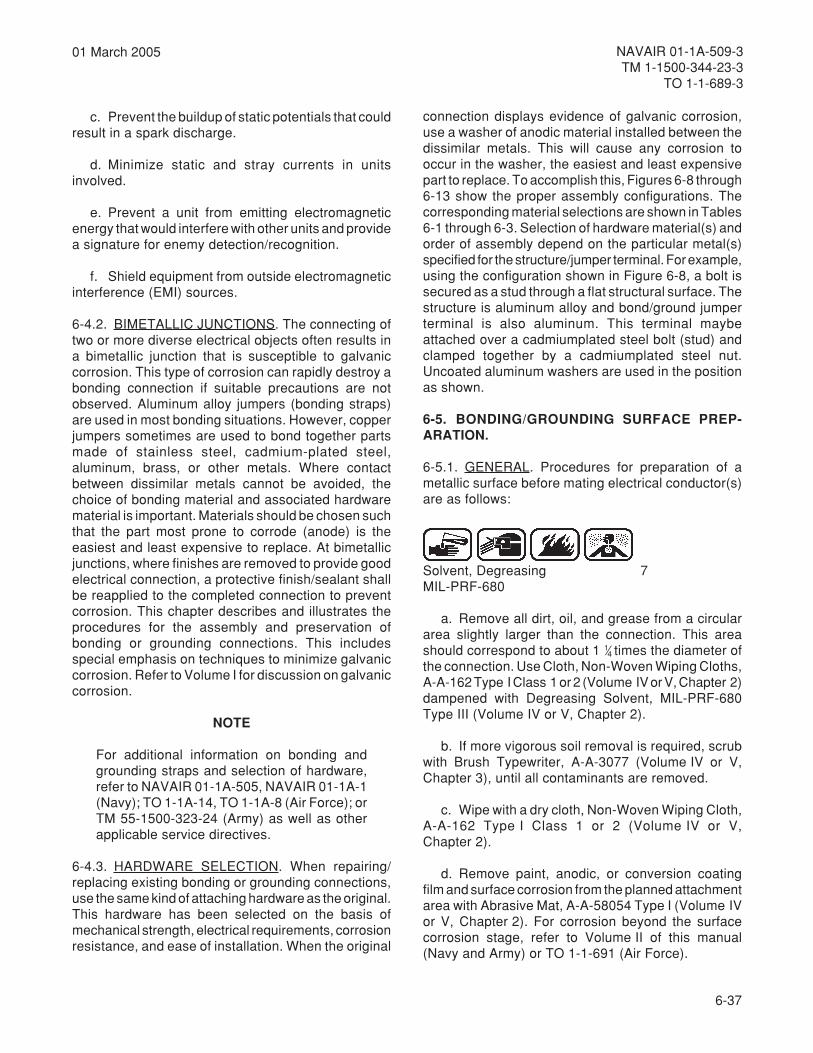
6-37
NAVAIR 01-1A-509-3TM 1-1500-344-23-3
TO 1-1-689-3
01 March 2005
c. Prevent the buildup of static potentials that couldresult in a spark discharge.
d. Minimize static and stray currents in unitsinvolved.
e. Prevent a unit from emitting electromagneticenergy that would interfere with other units and providea signature for enemy detection/recognition.
f. Shield equipment from outside electromagneticinterference (EMI) sources.
6-4.2. BIMETALLIC JUNCTIONS. The connecting oftwo or more diverse electrical objects often results ina bimetallic junction that is susceptible to galvaniccorrosion. This type of corrosion can rapidly destroy abonding connection if suitable precautions are notobserved. Aluminum alloy jumpers (bonding straps)are used in most bonding situations. However, copperjumpers sometimes are used to bond together partsmade of stainless steel, cadmium-plated steel,aluminum, brass, or other metals. Where contactbetween dissimilar metals cannot be avoided, thechoice of bonding material and associated hardwarematerial is important. Materials should be chosen suchthat the part most prone to corrode (anode) is theeasiest and least expensive to replace. At bimetallicjunctions, where finishes are removed to provide goodelectrical connection, a protective finish/sealant shallbe reapplied to the completed connection to preventcorrosion. This chapter describes and illustrates theprocedures for the assembly and preservation ofbonding or grounding connections. This includesspecial emphasis on techniques to minimize galvaniccorrosion. Refer to Volume I for discussion on galvaniccorrosion.
NOTE
For additional information on bonding andgrounding straps and selection of hardware,refer to NAVAIR 01-1A-505, NAVAIR 01-1A-1(Navy); TO 1-1A-14, TO 1-1A-8 (Air Force); orTM 55-1500-323-24 (Army) as well as otherapplicable service directives.
6-4.3. HARDWARE SELECTION. When repairing/replacing existing bonding or grounding connections,use the same kind of attaching hardware as the original.This hardware has been selected on the basis ofmechanical strength, electrical requirements, corrosionresistance, and ease of installation. When the original
connection displays evidence of galvanic corrosion,use a washer of anodic material installed between thedissimilar metals. This will cause any corrosion tooccur in the washer, the easiest and least expensivepart to replace. To accomplish this, Figures 6-8 through6-13 show the proper assembly configurations. Thecorresponding material selections are shown in Tables6-1 through 6-3. Selection of hardware material(s) andorder of assembly depend on the particular metal(s)specified for the structure/jumper terminal. For example,using the configuration shown in Figure 6-8, a bolt issecured as a stud through a flat structural surface. Thestructure is aluminum alloy and bond/ground jumperterminal is also aluminum. This terminal maybeattached over a cadmiumplated steel bolt (stud) andclamped together by a cadmiumplated steel nut.Uncoated aluminum washers are used in the positionas shown.
6-5. BONDING/GROUNDING SURFACE PREP-ARATION.
6-5.1. GENERAL. Procedures for preparation of ametallic surface before mating electrical conductor(s)are as follows:
Solvent, Degreasing 7MIL-PRF-680
a. Remove all dirt, oil, and grease from a circulararea slightly larger than the connection. This areashould correspond to about 1 1⁄4 times the diameter ofthe connection. Use Cloth, Non-Woven Wiping Cloths,A-A-162 Type I Class 1 or 2 (Volume IV or V, Chapter 2)dampened with Degreasing Solvent, MIL-PRF-680Type III (Volume IV or V, Chapter 2).
b. If more vigorous soil removal is required, scrubwith Brush Typewriter, A-A-3077 (Volume IV or V,Chapter 3), until all contaminants are removed.
c. Wipe with a dry cloth, Non-Woven Wiping Cloth,A-A-162 Type I Class 1 or 2 (Volume IV or V,Chapter 2).
d. Remove paint, anodic, or conversion coatingfilm and surface corrosion from the planned attachmentarea with Abrasive Mat, A-A-58054 Type I (Volume IVor V, Chapter 2). For corrosion beyond the surfacecorrosion stage, refer to Volume II of this manual(Navy and Army) or TO 1-1-691 (Air Force).

6-38
NAVAIR 01-1A-509-3TM 1-1500-344-23-3TO 1-1-689-3
01 March 2005
Table 6-1. Hardware for Stud Bonding or Grounding to Flat Surface
erutcurtS tloBrowercStuNkcoL&
tuNnialP **rehsaWA
**rehsaWB
**rehsaWD&C
rehsawkcoLE
rehsawkcoLF
repmuJdnalanimreTmunimulA
munimulAsyollA
muimdaCleetSdetalP
muimdaCleetSdetalP
munimulAyollA
munimulAyollA
muimdaCleetSdetalP
munimulAro
muimdaCleetSdetalP
muimdaCleetSdetalP
muisengaMsyollA
muimdaCleetSdetalP
muimdaCleetSdetalP
*muisengaMyollA
*muisengaMyollA
muimdaCleetSdetalP
munimulAro
muimdaCleetSdetalP
muimdaCleetSdetalP
,leetSmuimdaC
detalP
muimdaCleetSdetalP
muimdaCleetSdetalP
enoN enoN muimdaCleetSdetalP
munimulAro
muimdaCleetSdetalP
muimdaCleetSdetalP
,leetSnoisorroCtnatsiseR
noisorroCtnatsiseR
leetS
muimdaCleetSdetalP
enoN enoN muimdaCleetSdetalP
munimulAro
noisorroCtnatsiseR
leetS
muimdaCleetSdetalP
repmuJdnalanimreTreppoCdenniT
munimulAsyollA
muimdaCleetSdetalP
muimdaCleetSdetalP
munimulAyollA
munimulAyollA
muimdaCleetSdetalP
muimdaCleetSdetalP
muimdaCleetSdetalP
munimulAro
muisengaMsyollA
.muisengamotreppoctcennoctonoD:noituaC
,leetSmuimdaC
detalP
muimdaCleetSdetalP
muimdaCleetSdetalP
enoN enoN muimdaCleetSdetalP
muimdaCleetSdetalP
muimdaCleetSdetalP
,leetSnoisorroCtnatsiseR
noisorroCtnatsiseR
leetS
muimdaCleetSdetalP
enoN enoN muimdaCleetSdetalP
noisorroCtnatsiseR
leetS
muimdaCleetSdetalP
***
yollamunimulaesu,elbaliavatonnehW.tuohguorhtdesuebllahssrehsawmunimuladetaocnU
Figure 6-8. Stud Bonding or Grounding to Flat Surface
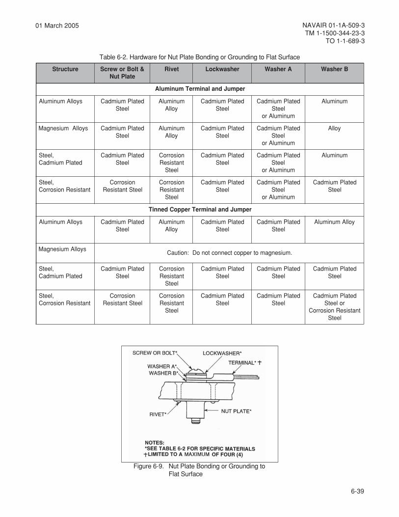
6-39
NAVAIR 01-1A-509-3TM 1-1500-344-23-3
TO 1-1-689-3
01 March 2005
Table 6-2. Hardware for Nut Plate Bonding or Grounding to Flat Surface
erutcurtS &tloBrowercSetalPtuN
teviR rehsawkcoL ArehsaW BrehsaW
repmuJdnalanimreTmunimulA
syollAmunimulA detalPmuimdaCleetS
munimulAyollA
detalPmuimdaCleetS
detalPmuimdaCleetS
munimulAro
munimulA
syollAmuisengaM detalPmuimdaCleetS
munimulAyollA
detalPmuimdaCleetS
detalPmuimdaCleetS
munimulAro
yollA
,leetSdetalPmuimdaC
detalPmuimdaCleetS
noisorroCtnatsiseR
leetS
detalPmuimdaCleetS
detalPmuimdaCleetS
munimulAro
munimulA
,leetStnatsiseRnoisorroC
noisorroCleetStnatsiseR
noisorroCtnatsiseR
leetS
detalPmuimdaCleetS
detalPmuimdaCleetS
munimulAro
detalPmuimdaCleetS
repmuJdnalanimreTreppoCdenniT
syollAmunimulA detalPmuimdaCleetS
munimulAyollA
detalPmuimdaCleetS
detalPmuimdaCleetS
yollAmunimulA
syollAmuisengaM.muisengamotreppoctcennoctonoD:noituaC
,leetSdetalPmuimdaC
detalPmuimdaCleetS
noisorroCtnatsiseR
leetS
detalPmuimdaCleetS
detalPmuimdaCleetS
detalPmuimdaCleetS
,leetStnatsiseRnoisorroC
noisorroCleetStnatsiseR
noisorroCtnatsiseR
leetS
detalPmuimdaCleetS
detalPmuimdaCleetS
detalPmuimdaCroleetS
tnatsiseRnoisorroCleetS
Figure 6-9. Nut Plate Bonding or Grounding toFlat Surface
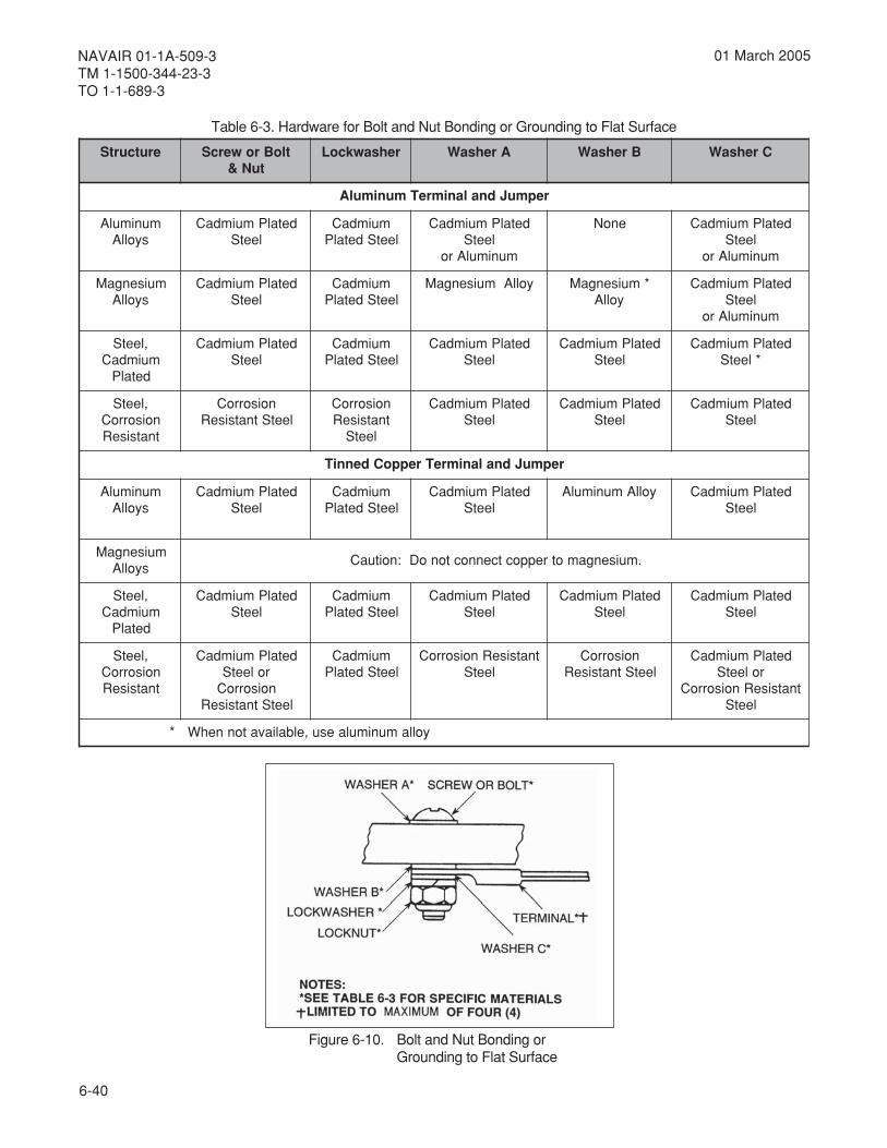
6-40
NAVAIR 01-1A-509-3TM 1-1500-344-23-3TO 1-1-689-3
01 March 2005
Table 6-3. Hardware for Bolt and Nut Bonding or Grounding to Flat Surface
erutcurtS tloBrowercStuN&
rehsawkcoL ArehsaW BrehsaW CrehsaW
repmuJdnalanimreTmunimulA
munimulAsyollA
detalPmuimdaCleetS
muimdaCleetSdetalP
detalPmuimdaCleetS
munimulAro
enoN detalPmuimdaCleetS
munimulAro
muisengaMsyollA
detalPmuimdaCleetS
muimdaCleetSdetalP
yollAmuisengaM *muisengaMyollA
detalPmuimdaCleetS
munimulAro
,leetSmuimdaC
detalP
detalPmuimdaCleetS
muimdaCleetSdetalP
detalPmuimdaCleetS
detalPmuimdaCleetS
detalPmuimdaC*leetS
,leetSnoisorroCtnatsiseR
noisorroCleetStnatsiseR
noisorroCtnatsiseR
leetS
detalPmuimdaCleetS
detalPmuimdaCleetS
detalPmuimdaCleetS
repmuJdnalanimreTreppoCdenniT
munimulAsyollA
detalPmuimdaCleetS
muimdaCleetSdetalP
detalPmuimdaCleetS
yollAmunimulA detalPmuimdaCleetS
muisengaMsyollA
.muisengamotreppoctcennoctonoD:noituaC
,leetSmuimdaC
detalP
detalPmuimdaCleetS
muimdaCleetSdetalP
detalPmuimdaCleetS
detalPmuimdaCleetS
detalPmuimdaCleetS
,leetSnoisorroCtnatsiseR
detalPmuimdaCroleetSnoisorroC
leetStnatsiseR
muimdaCleetSdetalP
tnatsiseRnoisorroCleetS
noisorroCleetStnatsiseR
detalPmuimdaCroleetS
tnatsiseRnoisorroCleetS
* yollamunimulaesu,elbaliavatonnehW
Figure 6-10. Bolt and Nut Bonding orGrounding to Flat Surface
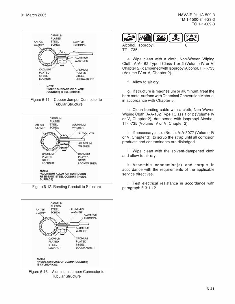
6-41
NAVAIR 01-1A-509-3TM 1-1500-344-23-3
TO 1-1-689-3
01 March 2005
Alcohol, Isopropyl 6TT-I-735
e. Wipe clean with a cloth, Non-Woven WipingCloth, A-A-162 Type I Class 1 or 2 (Volume IV or V,Chapter 2), dampened with Isopropyl Alcohol, TT-I-735(Volume IV or V, Chapter 2).
f. Allow to air dry.
g. If structure is magnesium or aluminum, treat thebare metal surface with Chemical Conversion Materialin accordance with Chapter 5.
h. Clean bonding cable with a cloth, Non-WovenWiping Cloth, A-A-162 Type I Class 1 or 2 (Volume IVor V, Chapter 2), dampened with Isopropyl Alcohol,TT-I-735 (Volume IV or V, Chapter 2).
i. If necessary, use a Brush, A-A-3077 (Volume IVor V, Chapter 3), to scrub the strap until all corrosionproducts and contaminants are dislodged.
j. Wipe clean with the solvent-dampened clothand allow to air dry.
k. Assemble connection(s) and torque inaccordance with the requirements of the applicableservice directives.
l. Test electrical resistance in accordance withparagraph 6-3.1.12.
Figure 6-11. Copper Jumper Connector toTubular Structure
Figure 6-12. Bonding Conduit to Structure
Figure 6-13. Aluminum Jumper Connector toTubular Structure

6-42
NAVAIR 01-1A-509-3TM 1-1500-344-23-3TO 1-1-689-3
01 March 2005
Compound, Corrosion Preventive 3Water-DisplacingMIL-C-81309
6-5.2. PRESERVATION. Apply Water DisplacingCorrosion Preventive Compound, MIL-C-81309 Type III(Volume IV or V, Chapter 2) according to Table 9-1.The following procedures apply for bonding/groundingconnections that are not environmentally protectedcontinually.
Compound, Corrosion Preventive 3Water-DisplacingMIL-C-81309
Compound, Corrosion Preventive 8MIL-PRF-16173
a. For bonding/grounding connections that requirefairly frequent disassembly, preserve the connectionarea by applying Corrosion Preventive Compound,MIL-C-81309 Type II (Volume IV or V, Chapter 2),followed by a coating of Corrosion PreventiveCompound, MIL-PRF-16173 Grade 4 (Volume IV or V,Chapter 2).
Sealing Compound 2Corrosion InhibitiveMIL-PRF-81733
Sealing Compound 19MIL-PRF-8516
b. For connections that seldom requiredisassembly, preserve with the more permanent andabrasion-resistant Sealing Compound, MIL-PRF-8516(Volume IV or V, Chapter 2), applied with a Spatula,A-A-277 (Volume IV or V, Chapter 3).
6-5.3. ELECTRONIC EQUIPMENT SHOCK MOUNTBONDING PRESERVATION. This type of electricalbonding uses a bonding wire (jumper assembly) orstrips of aluminum/copper. The following corrosionprevention method applies:
Alcohol, Isopropyl 6TT-I-735
a. Clean disassembled bonding connection bywiping with a cloth, Non-Woven Wiping Cloth, A-A-162Type I Class 1 or 2 (Volume IV or V, Chapter 2),dampened with Isopropyl Alcohol, TT-I-735 (Volume IVor V, Chapter 2).
b. Allow to air dry.
c. Assemblebondingconnection.
Compound, Corrosion Preventive 3Water-DisplacingMIL-C-81309
d. Apply Water Displacing, Corrosion PreventiveCompound, MIL-C-81309 Type II (Volume IV or V,Chapter 2), over jumper assembly.
Sealing Compound 2Corrosion InhibitiveMIL-PRF-81733
e. For connections seldom requiring disassembly,coat the entire connection with Corrosion InhibitingSealant, MIL-PRF-81733 Class 1, Grade A Type II - 1/2 (Volume IV or V, Chapter 2) using a sealant gun; andsmooth out with a Spatula, ZZ-S-70 (A-A-227)(Volume IV or V, Chapter 3) to ensure completecoverage. This sealant will cure to a tack free state in10 hours.
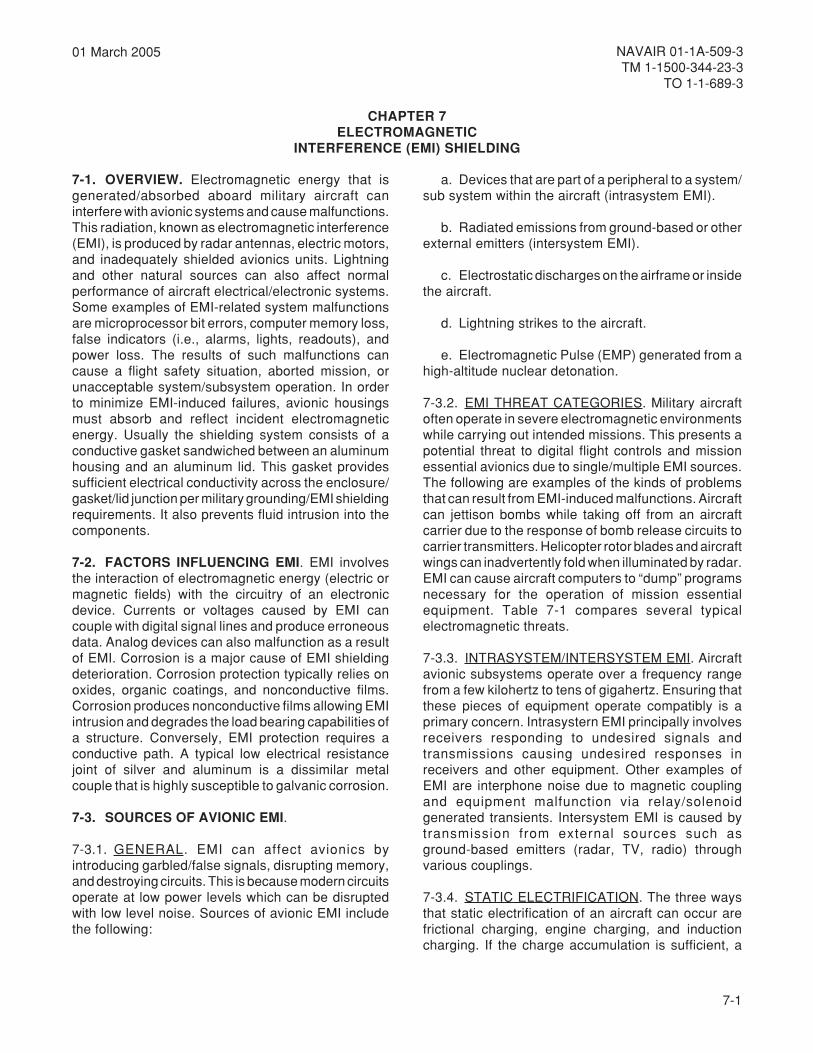
7-1
NAVAIR 01-1A-509-3TM 1-1500-344-23-3
TO 1-1-689-3
01 March 2005
CHAPTER 7ELECTROMAGNETIC
INTERFERENCE (EMI) SHIELDING
7-1. OVERVIEW. Electromagnetic energy that isgenerated/absorbed aboard military aircraft caninterfere with avionic systems and cause malfunctions.This radiation, known as electromagnetic interference(EMI), is produced by radar antennas, electric motors,and inadequately shielded avionics units. Lightningand other natural sources can also affect normalperformance of aircraft electrical/electronic systems.Some examples of EMI-related system malfunctionsare microprocessor bit errors, computer memory loss,false indicators (i.e., alarms, lights, readouts), andpower loss. The results of such malfunctions cancause a flight safety situation, aborted mission, orunacceptable system/subsystem operation. In orderto minimize EMI-induced failures, avionic housingsmust absorb and reflect incident electromagneticenergy. Usually the shielding system consists of aconductive gasket sandwiched between an aluminumhousing and an aluminum lid. This gasket providessufficient electrical conductivity across the enclosure/gasket/lid junction per military grounding/EMI shieldingrequirements. It also prevents fluid intrusion into thecomponents.
7-2. FACTORS INFLUENCING EMI. EMI involvesthe interaction of electromagnetic energy (electric ormagnetic fields) with the circuitry of an electronicdevice. Currents or voltages caused by EMI cancouple with digital signal lines and produce erroneousdata. Analog devices can also malfunction as a resultof EMI. Corrosion is a major cause of EMI shieldingdeterioration. Corrosion protection typically relies onoxides, organic coatings, and nonconductive films.Corrosion produces nonconductive films allowing EMIintrusion and degrades the load bearing capabilities ofa structure. Conversely, EMI protection requires aconductive path. A typical low electrical resistancejoint of silver and aluminum is a dissimilar metalcouple that is highly susceptible to galvanic corrosion.
7-3. SOURCES OF AVIONIC EMI.
7-3.1. GENERAL. EMI can affect avionics byintroducing garbled/false signals, disrupting memory,and destroying circuits. This is because modern circuitsoperate at low power levels which can be disruptedwith low level noise. Sources of avionic EMI includethe following:
a. Devices that are part of a peripheral to a system/sub system within the aircraft (intrasystem EMI).
b. Radiated emissions from ground-based or otherexternal emitters (intersystem EMI).
c. Electrostatic discharges on the airframe or insidethe aircraft.
d. Lightning strikes to the aircraft.
e. Electromagnetic Pulse (EMP) generated from ahigh-altitude nuclear detonation.
7-3.2. EMI THREAT CATEGORIES. Military aircraftoften operate in severe electromagnetic environmentswhile carrying out intended missions. This presents apotential threat to digital flight controls and missionessential avionics due to single/multiple EMI sources.The following are examples of the kinds of problemsthat can result from EMI-induced malfunctions. Aircraftcan jettison bombs while taking off from an aircraftcarrier due to the response of bomb release circuits tocarrier transmitters. Helicopter rotor blades and aircraftwings can inadvertently fold when illuminated by radar.EMI can cause aircraft computers to “dump” programsnecessary for the operation of mission essentialequipment. Table 7-1 compares several typicalelectromagnetic threats.
7-3.3. INTRASYSTEM/INTERSYSTEM EMI. Aircraftavionic subsystems operate over a frequency rangefrom a few kilohertz to tens of gigahertz. Ensuring thatthese pieces of equipment operate compatibly is aprimary concern. Intrasystern EMI principally involvesreceivers responding to undesired signals andtransmissions causing undesired responses inreceivers and other equipment. Other examples ofEMI are interphone noise due to magnetic couplingand equipment malfunction via relay/solenoidgenerated transients. Intersystem EMI is caused bytransmission from external sources such asground-based emitters (radar, TV, radio) throughvarious couplings.
7-3.4. STATIC ELECTRIFICATION. The three waysthat static electrification of an aircraft can occur arefrictional charging, engine charging, and inductioncharging. If the charge accumulation is sufficient, a

7-2
NAVAIR 01-1A-509-3TM 1-1500-344-23-3TO 1-1-689-3
01 March 2005
metsysretnI/artnIcitengamortcelE
)IME(ecnerefretnI
citatSnoitacifirtcelE
gninthgiLcitengamortcelE
)PME(esluP
taerhTerusopxE
lacoLdetaler-annetnayllausU
lacoLdetaler-elcitrapyllausU
lacoLdetaler-duolcyllausU
lanoigeRdetalertsrubraelcuN
foerutaNtnemnorivnE
edam-naMtneisnartrosuounitnoC
slangisdellortnocnu/dellortnoCnwonkyllaitrap,nwonK
egrahcsidkraps/anoroCsremaertS
dellortnocnUnwonknU
larutaNegrahcsidcrA
dellortnocnUnwonkyllaitraP
edam-naMtneisnartevawenalP
dellortnocnUnwonkyllaitraP
stceffE decudnItceriD
decudnI tceriDdecudnI
decudnI
ytilacitirC noissimytefasthgilF noissiM noissimytefasthgilF noissimytefasthgilF
taerhTmurtcepS
dnabworran/dnabdaorB)zHG001otpu(
dnabdaorB)zHM001otpu(
dnabdaorB)zHM001otpu(
dnabdaorB)zHM001otpu(
sisylanA gnilpuoctna/tnAgnilpuoctna/eriWgnilpuoceriw/tnAgnilpuoceriw/eriW
gnilpuoctna/dleiFgnilpuoceriw/dleiF
gnilpuoctna/dleiFgnilpuoceriw/dleiFeruliaftnenopmoC
lavivrusfoytilibaborP
gnilpuoctna/dleiFgnilpuoceriw/dleiFeruliaftnenopmoC
lavivrusfoytilibaborP
gnitseT /detaidarlevel-piuqE/noissimedetcudnoc
ytilibitpecsusthgilf-fo-ytefaSthgilf-ni/dnuorG
CDegatlovhgiHelcitrapdegrahC
tnemdrabmob
esluptnerruc-hgiHtniop-tnemhcattA
noitcejniniPnoitcudnielbaC
dleif-eerFnoitcejniniP
noitcudnielbaC
noitcetorPserusaeM
gnidleihSgniretliFgnidnoB
gnidnuorGsretimiL
ngisedtiucriCngisederawtfoS
tnemeganamycneuqerFtnempiuqe/elbaC
tnemecalpscitporebiF
segrahcsiDseuqinhcetlortnocIME
sretreviDsretserraegruS
seuqinhcetlortnocIME
seuqinhcetlortnocIME
noitcetorPecnarussA
erusopxelanoitarepOecruosesioN
noitagitsevninoitcudergnilpuoC
serusaeM
erusopxelanoitarepOnoitcetedecruosesioN
gnidnobevitcerroCtnemeganamegrahcsiD
erusopxelanoitarepOnoitagitsevnipahsiMtnemecalper/riapeR
erusopxeemitecaepoNecnallievrusgnirruceR
tnemecalper/riapeR
DTS-LIMecnerefeR
164-DTS-LIM464-DTS-LIM
464-DTS-LIM 464-DTS-LIM enoN
Table 7-1. Military Aircraft Electromagnetic Threat Comparison

7-3
NAVAIR 01-1A-509-3TM 1-1500-344-23-3
TO 1-1-689-3
01 March 2005
number of interference generating processes canoccur. First, if the total aircraft structure is charged,electric fields at its extremities can become sufficientto cause arcing. Second, if insulated dielectric surfacesare charged, such as a windshield or radome, spark-likedischarges across the dielectric surface to thesurrounding metal structure can result. Third, if isolated(unbonded) metal sections of the aircraft becomecharged, arcing to adjacent metal structures can occur.Finally, slowly varying induction pulses can be producedin antennas moving through clouds of charged particles.These processes create an uncontrolledelectromagnetic environment that generally impactsreceiver inputs via antennas. This degrades theoperational performance of navigation andcommunication equipment. Broadband digital systemscan also be affected because discharges occur aspulses that may be misinterpreted as control signals.Chapter 8 provides more in depth theory on electrostaticdischarge (ESD) as it relates to military avionicequipment, modules, and components.
7-3.5. LIGHTNING. Lightning is probably the mostsevere uncontrolled electromagnetic environment towhich aircraft are exposed. The severity of the lightningthreat depends on the probability of a lightning strike tothe aircraft. Lightning strike is a function of weather,temperature, geographical region, aircraft altitude,aircraft type, and other parameters. Statistics showthat an aircraft experiences less than one strike every3000 hours of flight operation. The damage from alightning strike to the aircraft depends on itscharacteristics, such as peak current, rate-of-rise,risetime, charge, action integral, and number ofsubsequent strikes. The direct effects of a lightningstrike are burning, eroding, blasting and structuraldeformation caused by arcing. Also, high pressureshock waves and magnetic forces are produced by theassociated high currents. These effects pose greatdangers to flight safety in addition to aborted missions.The indirect (induced) effects result mostly from theinteraction of electromagnetic fields with electrical/electronic circuits. These effects also can be hazardoussince lightning may generate high voltages and currentsin circuits through coupling mechanisms.
7-3.6. ELECTROMAGNETIC PULSE. EMP is a threatto military electronics which arises primarily from highaltitude nuclear detonations. Gamma rays produced inthe explosion interact with air molecules andparticulates with sufficient energy to eject electrons.
These electrons interact with the earth’s magneticfield, radiating high intensity fields. Field strengths canbe on the order of 50,000 volts per meter with pulsedurations of hundreds of nanoseconds. The large skincurrents generated on the surface of an enclosurerequire that joint impedances are low. This preventslarge voltage drops at these discontinuities in theshield. The characteristics of EMP appear to be verysimilar to that of the lightning transient. The differencesare in pulse risetime, rate-of-rise, and pulse duration.
7-4. EMI SHIELDING.
7-4.1. EMI SHIELDING PRACTICES. Some form ofEMI shielding is required for avionics aboard all modemmilitary aircraft. Shielding is used to protect avionicsfrom the electromagnetic environment present in fieldservice. Shielding is accomplished by enclosingelectronic equipment in a conductive shell or enclosure(Faraday cage). The enclosure reduces the incidentelectromagnetic energy to tolerable levels by reflectionand absorption. Radiation incident on the interior andexterior surfaces does not escape or penetrate theenclosure. Openings in the shield required for power/signal cables, covers and access doors, ventilation,and windows allow EMI leakage. Shielding for theseopenings usually takes the form of gaskets, seals, orjoints that provide electrical continuity across voids toensure a continuous protective shell. In addition, thisshielding also aids lightning strike protection byproviding a conductive path. Performance of an EMIshielding system is a function of the weakestcomponent. Shielding effectiveness of the variouscomponents (wall material, access doors, vents,cabling, connectors, joint seals) should be maintained.Changes in the shielding effectiveness of individualcomponents over time should be correctable throughroutine maintenance. Conditions that can inhibit thelife and shielding effectiveness of EMI gaskets are:
a. The environment in which a gasket is stored.
b. The environment in which the gasketed joint is tobe used.
c. The force on the gasketed joint.
d. The unevenness of the joint.
7-4.2. EMI SHIELDING EFFECTIVENESS. Whenelectromagnetic energy impinges on a conductivebarrier, a portion of the energy is reflected/transmitted.
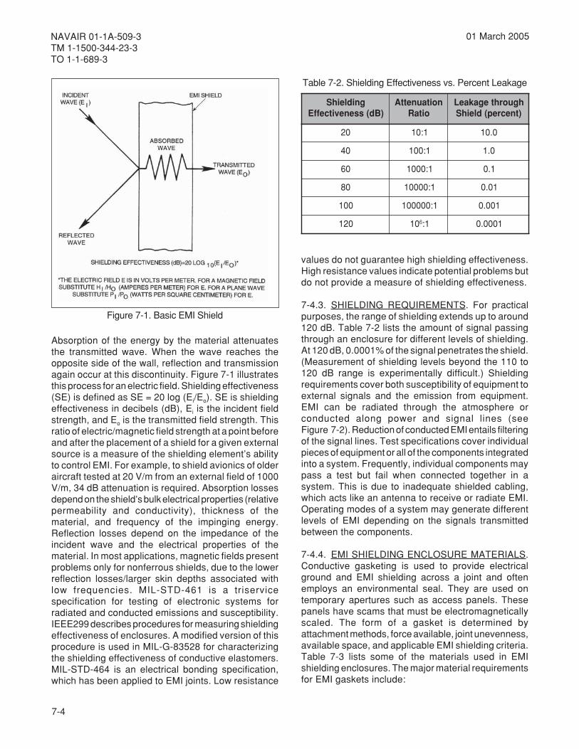
7-4
NAVAIR 01-1A-509-3TM 1-1500-344-23-3TO 1-1-689-3
01 March 2005
Absorption of the energy by the material attenuatesthe transmitted wave. When the wave reaches theopposite side of the wall, reflection and transmissionagain occur at this discontinuity. Figure 7-1 illustratesthis process for an electric field. Shielding effectiveness(SE) is defined as SE = 20 log (Ei/Eo). SE is shieldingeffectiveness in decibels (dB), Ei is the incident fieldstrength, and Eo is the transmitted field strength. Thisratio of electric/magnetic field strength at a point beforeand after the placement of a shield for a given externalsource is a measure of the shielding element’s abilityto control EMI. For example, to shield avionics of olderaircraft tested at 20 V/m from an external field of 1000V/m, 34 dB attenuation is required. Absorption lossesdepend on the shield’s bulk electrical properties (relativepermeability and conductivity), thickness of thematerial, and frequency of the impinging energy.Reflection losses depend on the impedance of theincident wave and the electrical properties of thematerial. In most applications, magnetic fields presentproblems only for nonferrous shields, due to the lowerreflection losses/larger skin depths associated withlow frequencies. MIL-STD-461 is a triservicespecification for testing of electronic systems forradiated and conducted emissions and susceptibility.IEEE299 describes procedures for measuring shieldingeffectiveness of enclosures. A modified version of thisprocedure is used in MIL-G-83528 for characterizingthe shielding effectiveness of conductive elastomers.MIL-STD-464 is an electrical bonding specification,which has been applied to EMI joints. Low resistance
values do not guarantee high shielding effectiveness.High resistance values indicate potential problems butdo not provide a measure of shielding effectiveness.
7-4.3. SHIELDING REQUIREMENTS. For practicalpurposes, the range of shielding extends up to around120 dB. Table 7-2 lists the amount of signal passingthrough an enclosure for different levels of shielding.At 120 dB, 0.0001% of the signal penetrates the shield.(Measurement of shielding levels beyond the 110 to120 dB range is experimentally difficult.) Shieldingrequirements cover both susceptibility of equipment toexternal signals and the emission from equipment.EMI can be radiated through the atmosphere orconducted along power and signal lines (seeFigure 7-2). Reduction of conducted EMI entails filteringof the signal lines. Test specifications cover individualpieces of equipment or all of the components integratedinto a system. Frequently, individual components maypass a test but fail when connected together in asystem. This is due to inadequate shielded cabling,which acts like an antenna to receive or radiate EMI.Operating modes of a system may generate differentlevels of EMI depending on the signals transmittedbetween the components.
7-4.4. EMI SHIELDING ENCLOSURE MATERIALS.Conductive gasketing is used to provide electricalground and EMI shielding across a joint and oftenemploys an environmental seal. They are used ontemporary apertures such as access panels. Thesepanels have scams that must be electromagneticallyscaled. The form of a gasket is determined byattachment methods, force available, joint unevenness,available space, and applicable EMI shielding criteria.Table 7-3 lists some of the materials used in EMIshielding enclosures. The major material requirementsfor EMI gaskets include:
Figure 7-1. Basic EMI Shield
gnidleihS)Bd(ssenevitceffE
noitaunettAoitaR
hguorhtegakaeL)tnecrep(dleihS
02 1:01 0.01
04 1:001 0.1
06 1:0001 1.0
08 1:00001 10.0
001 1:000001 100.0
021 01 6 1: 1000.0
Table 7-2. Shielding Effectiveness vs. Percent Leakage
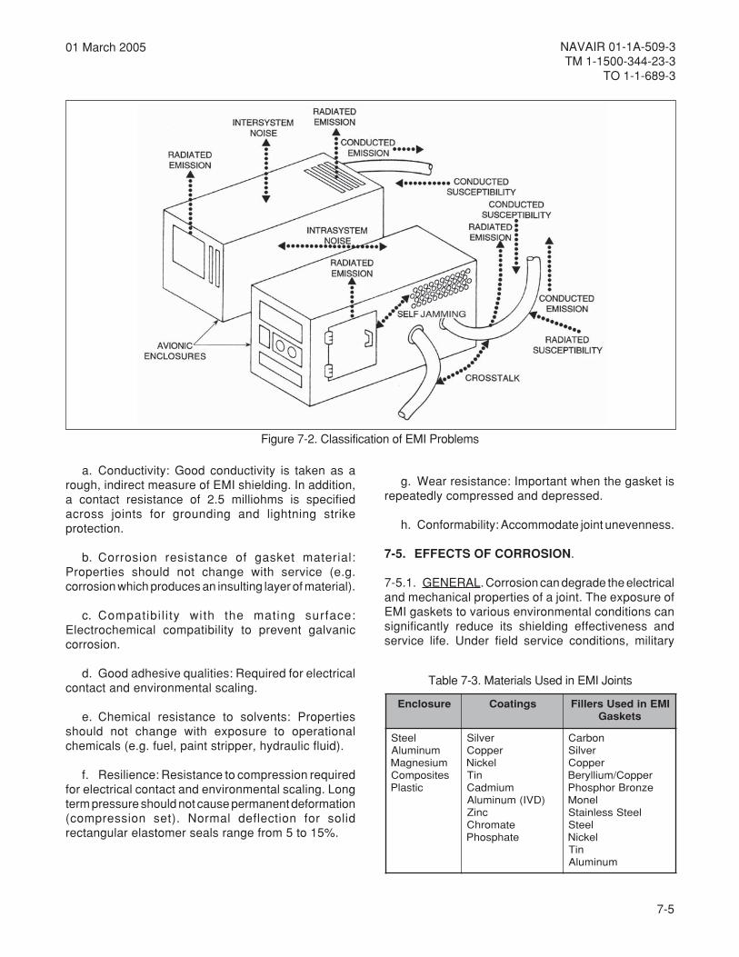
7-5
NAVAIR 01-1A-509-3TM 1-1500-344-23-3
TO 1-1-689-3
01 March 2005
a. Conductivity: Good conductivity is taken as arough, indirect measure of EMI shielding. In addition,a contact resistance of 2.5 milliohms is specifiedacross joints for grounding and lightning strikeprotection.
b. Corrosion resistance of gasket material:Properties should not change with service (e.g.corrosion which produces an insulting layer of material).
c. Compatibi l i ty with the mating surface:Electrochemical compatibility to prevent galvaniccorrosion.
d. Good adhesive qualities: Required for electricalcontact and environmental scaling.
e. Chemical resistance to solvents: Propertiesshould not change with exposure to operationalchemicals (e.g. fuel, paint stripper, hydraulic fluid).
f. Resilience: Resistance to compression requiredfor electrical contact and environmental scaling. Longterm pressure should not cause permanent deformation(compression set). Normal deflection for solidrectangular elastomer seals range from 5 to 15%.
Figure 7-2. Classification of EMI Problems
erusolcnE sgnitaoC IMEnidesUsrelliFsteksaG
leetSmunimulA
muisengaMsetisopmoC
citsalP
revliSreppoC
lekciNniT
muimdaC)DVI(munimulA
cniZetamorhCetahpsohP
nobraCrevliS
reppoCreppoC/muillyreBeznorBrohpsohP
lenoMleetSsselniatS
leetSlekciN
niTmunimulA
Table 7-3. Materials Used in EMI Joints
g. Wear resistance: Important when the gasket isrepeatedly compressed and depressed.
h. Conformability: Accommodate joint unevenness.
7-5. EFFECTS OF CORROSION.
7-5.1. GENERAL. Corrosion can degrade the electricaland mechanical properties of a joint. The exposure ofEMI gaskets to various environmental conditions cansignificantly reduce its shielding effectiveness andservice life. Under field service conditions, military
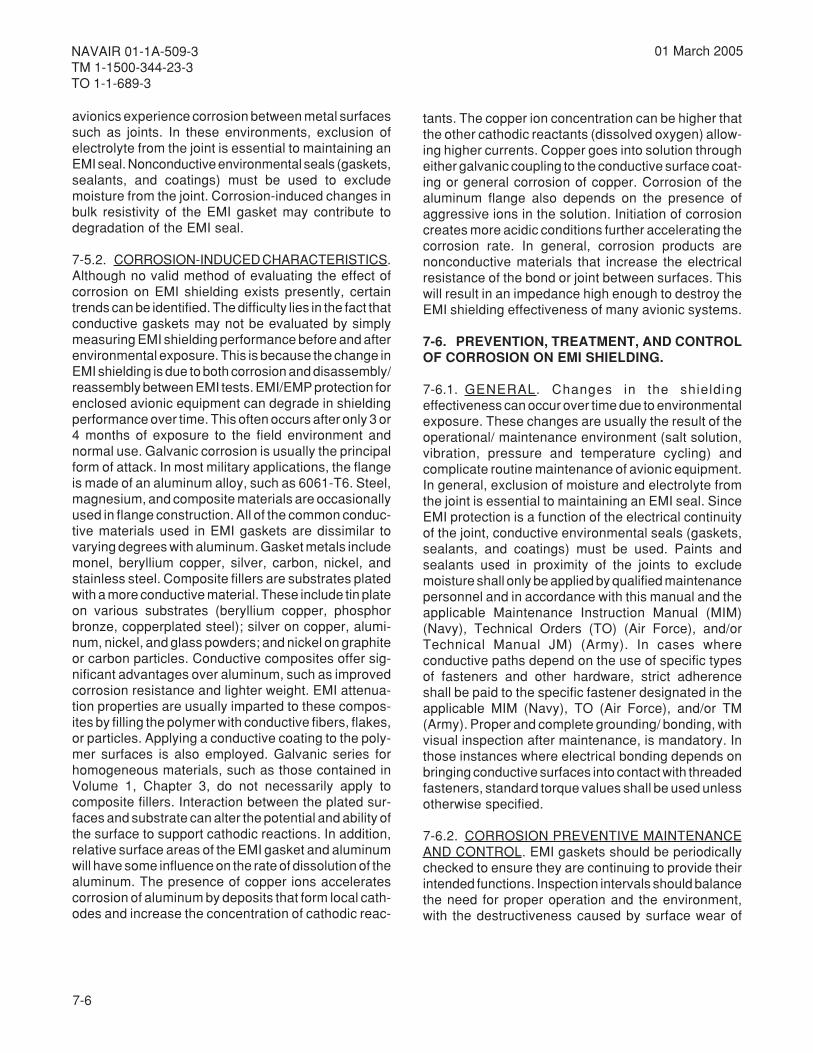
7-6
NAVAIR 01-1A-509-3TM 1-1500-344-23-3TO 1-1-689-3
01 March 2005
avionics experience corrosion between metal surfacessuch as joints. In these environments, exclusion ofelectrolyte from the joint is essential to maintaining anEMI seal. Nonconductive environmental seals (gaskets,sealants, and coatings) must be used to excludemoisture from the joint. Corrosion-induced changes inbulk resistivity of the EMI gasket may contribute todegradation of the EMI seal.
7-5.2. CORROSION-INDUCED CHARACTERISTICS.Although no valid method of evaluating the effect ofcorrosion on EMI shielding exists presently, certaintrends can be identified. The difficulty lies in the fact thatconductive gaskets may not be evaluated by simplymeasuring EMI shielding performance before and afterenvironmental exposure. This is because the change inEMI shielding is due to both corrosion and disassembly/reassembly between EMI tests. EMI/EMP protection forenclosed avionic equipment can degrade in shieldingperformance over time. This often occurs after only 3 or4 months of exposure to the field environment andnormal use. Galvanic corrosion is usually the principalform of attack. In most military applications, the flangeis made of an aluminum alloy, such as 6061-T6. Steel,magnesium, and composite materials are occasionallyused in flange construction. All of the common conduc-tive materials used in EMI gaskets are dissimilar tovarying degrees with aluminum. Gasket metals includemonel, beryllium copper, silver, carbon, nickel, andstainless steel. Composite fillers are substrates platedwith a more conductive material. These include tin plateon various substrates (beryllium copper, phosphorbronze, copperplated steel); silver on copper, alumi-num, nickel, and glass powders; and nickel on graphiteor carbon particles. Conductive composites offer sig-nificant advantages over aluminum, such as improvedcorrosion resistance and lighter weight. EMI attenua-tion properties are usually imparted to these compos-ites by filling the polymer with conductive fibers, flakes,or particles. Applying a conductive coating to the poly-mer surfaces is also employed. Galvanic series forhomogeneous materials, such as those contained inVolume 1, Chapter 3, do not necessarily apply tocomposite fillers. Interaction between the plated sur-faces and substrate can alter the potential and ability ofthe surface to support cathodic reactions. In addition,relative surface areas of the EMI gasket and aluminumwill have some influence on the rate of dissolution of thealuminum. The presence of copper ions acceleratescorrosion of aluminum by deposits that form local cath-odes and increase the concentration of cathodic reac-
tants. The copper ion concentration can be higher thatthe other cathodic reactants (dissolved oxygen) allow-ing higher currents. Copper goes into solution througheither galvanic coupling to the conductive surface coat-ing or general corrosion of copper. Corrosion of thealuminum flange also depends on the presence ofaggressive ions in the solution. Initiation of corrosioncreates more acidic conditions further accelerating thecorrosion rate. In general, corrosion products arenonconductive materials that increase the electricalresistance of the bond or joint between surfaces. Thiswill result in an impedance high enough to destroy theEMI shielding effectiveness of many avionic systems.
7-6. PREVENTION, TREATMENT, AND CONTROLOF CORROSION ON EMI SHIELDING.
7-6.1. GENERAL. Changes in the shieldingeffectiveness can occur over time due to environmentalexposure. These changes are usually the result of theoperational/ maintenance environment (salt solution,vibration, pressure and temperature cycling) andcomplicate routine maintenance of avionic equipment.In general, exclusion of moisture and electrolyte fromthe joint is essential to maintaining an EMI seal. SinceEMI protection is a function of the electrical continuityof the joint, conductive environmental seals (gaskets,sealants, and coatings) must be used. Paints andsealants used in proximity of the joints to excludemoisture shall only be applied by qualified maintenancepersonnel and in accordance with this manual and theapplicable Maintenance Instruction Manual (MIM)(Navy), Technical Orders (TO) (Air Force), and/orTechnical Manual JM) (Army). In cases whereconductive paths depend on the use of specific typesof fasteners and other hardware, strict adherenceshall be paid to the specific fastener designated in theapplicable MIM (Navy), TO (Air Force), and/or TM(Army). Proper and complete grounding/ bonding, withvisual inspection after maintenance, is mandatory. Inthose instances where electrical bonding depends onbringing conductive surfaces into contact with threadedfasteners, standard torque values shall be used unlessotherwise specified.
7-6.2. CORROSION PREVENTIVE MAINTENANCEAND CONTROL. EMI gaskets should be periodicallychecked to ensure they are continuing to provide theirintended functions. Inspection intervals should balancethe need for proper operation and the environment,with the destructiveness caused by surface wear of

7-7
NAVAIR 01-1A-509-3TM 1-1500-344-23-3
TO 1-1-689-3
01 March 2005
gaskets with disassembly/ reassembly. Gaskets maydeteriorate via attack by operational chemicals,corrosion, and wear. Therefore, inspection shouldinclude the following.
a. Check for corrosion products, pitting of thealuminum surface, or bulges in the sealant due tocorrosion beneath the gaskets.
b. Check the bonding of the gasket to the structureto prevent moisture intrusion.
c. Check for loss of electrical conductivity of thegasket or its electrical bond to the aircraft.
d. Check for wear and swelling of the gasket.
e. Check for compression set of the seal.
f. Insure maintenance procedures are beingfollowed (e.g. avoid solvents which can wash awayconductive particles).
g. Check for excessive bending and/or pulling ofelectrical cables and shields.
7-6.3. EMI SHIELDING CORROSION REPAIR ANDTREATMENT. Corrective maintenance of EMI gasketsdepends on the type of gasket involved, size of thedamaged area, and degree/type of corrosion. EMIgaskets are usually of either metal or conductiveelastomer construction. Finger stock, mesh, and spiralribbon are examples of metal gaskets. Conductiveelastomers consist of dispersions of conductiveparticles (spheres, irregular shapes, fibers) in elastomermatrices. Oriented wire gaskets have characteristicsof both categories. Since each type of EMI gasket hasits own peculiarities, each will require special corrosiontreatment/repair. The following “generic” gasket repairprocedure is outlined below for general guidance.Maintenance personnel should refer to the applicableMIM (Navy), TO (Air Force), and/or TM (Army) for morespecific repair information.
a. When corrosion is observed, disassemble onlythe affected area and remove the corrosion using themildest available method.
Compound, Corrosion Preventive 3Water DisplacingMIL-C-81309
Alcohol, Isopropyl 6TT-I-735
b. Carefully clean the area with Isopropyl Alcohol,TT-I-735 (Volume IV or V, Chapter 2). If replacementseals are available, install them in accordance withaircraft maintenance instructions or bulletins. Ifreplacement seals are not available or do not exist,spray the contacting surfaces with a light coating ofWater Displacing Corrosion Preventive Compound,MIL-C-81309 Type II (Volume IV or V, Chapter 2) andthen reassemble.
c. Inspect repairs and areas known to be chronicproblems often.
7-6.3.1. (AF) Electronically Conductive, CorrosiveInhibiting Sealant for EMI Suppression Applications.Many electrically conductive sealants are available,but most are not corrosion inhibiting and generategalvanic corrosion at bond lines when contactingaluminum and/or steel alloys in the presence ofmoisture. SAE Specification AMS 3262 covers anelectrically conductive, corrosion inhibiting sealantthat can be used in EMI suppression applicationswithout causing a galvanic corrosion problem. Thismaterial can be used to bond EMI gaskets to one of twomating surfaces, to bond and seal two mating metalsurfaces fastened in a permanent joint, or to fillet sealthe edges of a metal-to-metal lap or butt type jointwhile in each case providing electrical conductivitybetween all components. See Volume V, Chapter 2 forsealant ordering information. Application proceduresare as follows:
a. If present, remove all paint and primer from allmetal surfaces that will contact the sealant per TO1-1-8 procedures, and lightly abrade these surfaceswith an Abrasive Mat, A-A-58054 Type I Grade B(Volume V, Chapter 2).

7-8
NAVAIR 01-1A-509-3TM 1-1500-344-23-3TO 1-1-689-3
01 March 2005
Alcohol, Isopropyl 6TT-I-735
b. Clean all surfaces that will contact the sealantwith a lint free cloth (Volume V, Chapter 2) moistenedwith Isopropyl Alcohol, TT-I-735 (Volume V, Chapter 2),and then wipe the areas dry with a clean cloth of thesame type. Do not allow drying by evaporation or touchthe cleaned areas with bare hands as this willrecontaminate the surfaces and prevent adhesion ofthe sealant.
NOTE
All sealant and primer application operationsand component assembly operations after thesealant application shall be performed withinthe temperature range of 60°F to 95°F so thatthe sealant will adhere properly.
WARNING
Sealants and primers are flammable and toxic.Skin and eye protection are required. Avoid allsources of ignition. Good general ventilation isnormally adequate.
c. If required by the sealant manufacturer, obtainthe appropriate adhesive primer (Volume V, Chapter 2).Apply it to the surfaces that will contact the sealant perthe manufacturer’s instructions; allow it to cure for atleast 1⁄2 but not more than 4 hours before applying thesealant. If more than 4 hours elapse after the primerapplication, repeat steps a, b, and c before applyingthe sealant.
d. Choose a sealant (Volume V, Chapter 2). If it isa multi-component sealant, mix the componentstogether per the manufacturer’s instructions.
NOTE
To case clean up of excess sealant, MaskingTape, SAE-AMS-T-21595, Type I (Volume V,Chapter 2) can be applied to the surface oneach side of the area to which sealant will beapplied. Install the tape before the sealant isapplied, and remove it as soon as possibleafter the sealant is smoothed out.
e. Apply a bead of sealant to the surface to whichthe EMI gasket will be bonded, one of the two matingmetal surfaces that will be permanently assembled tothe edge of a lap joint, or the gap of a butt joint(whatever situation applies), using a sealant gun or asqueezable sealant tube. Using a straight edged woodor plastic tool, smooth the sealant bead to form acontinuous film over the entire contact surface for theEMI gasket or the mating metal surface of a permanentassembly as applicable, or smooth the bead at the lapjoint edge to an even, continuous fillet or smooth thebead in the butt joint gap to fill the gap entirely and beflush with the surface, as applicable.
f. Press the EMI gasket into the sealant or assemblethe sealant coated surface to the sealant free matingsurface of a permanent assemble, as applicable, whilethe sealant is wet or within the manufacturer’s specifiedapplication life.
Alcohol, Isopropyl 6TT-I-735
g. Clean up any excess sealant with a lint free cloth(Volume V, Chapter 2) moistened with IsopropylAlcohol, TT-I-735 (Volume V, Chapter 2) while thesealant is still wet.
h. Allow the sealant to cure for the t imerecommended by the manufacturer, but not less than24 hours, before placing the equipment in service.
7-7. EMI PACKAGING REQUIREMENTS. Unlessotherwise specified, items that are sensitive to EMIshould be packaged in accordance with MIL-E-17555for electromagnetic protection. Marking shall beaccordance with MIL-STD-129.

8-1
NAVAIR 01-1A-509-3TM 1-1500-344-23-3
TO 1-1-689-3
01 March 2005
CHAPTER 8ELECTROSTATIC DISCHARGE (ESD)
8-1. OVERVIEW.
8-1.1. GENERAL. Very Large Scale Integration (VLSI)digital components are steadily increasing in functionalpower, speed, and system applications in militaryavionics. By making the VLSI devices small, lessvoltage is needed to operate circuitry and the noiseimmunity decreases. Many of these devices are highlysusceptible to damage from the discharge of staticelectricity. Electrostatic discharge (ESD) affects manycomponents such as transistors, resistors, integratedcircuits (ICs), and other types of semiconductordevices. A spark discharge resulting from theaccumulation of electrostatic charges may notimmediately destroy a device or cause it to becomenonfunctional. The device can be permanentlydamaged, yet perform its intended function. Additionalexposure to spark discharges or continued use of thedevice can further damage the item until failure occurs.This is known as a latent failure and can seriouslyaffect a system's reliability. It is essential that everyoneinvolved in the repair handling, transporting, and storingof electrostatic discharge sensitive (ESDS) items beconcerned about ESD. All ESDS items should bepackaged, shipped, and stored in ESD protectivematerials. Further information on the Air Force ESDprogram is contained in TO 00-25-234.
8-1.2. DEFINITION. ESD is the transfer of electrostaticcharge between bodies with different electrostaticpotentials. This is caused by direct contact or inducedby an electrostatic field. The most formidable ESD islightning or electromagnetic pulse (EMP). Dischargesfrom human bodies are the most frequent, leastnoticeable, and most ignored ESD. ESD affectselectronic devices in a number of different ways. It candegrade performance, change the electricalcharacteristics, or cause complete failure of the device.
8-1.3. FAILURE MECHANISMS. Three of the mostcommon failure mechanisms are junction burnout,oxide punchthrough, and metallization burnout.Junction burnout usually occurs in bipolar discreteand integrated circuits. Metal Oxide Semiconductor(MOS) discrete and integrated circuits often experienceoxide punch through. Metallization burnout is usuallyassociated with both bipolar and MOS ICs. Thefollowing paragraphs describe some of the
mechanisms that cause avionics to fail in field serviceand storage. In addition, procedures are outlined toprevent these failures from occurring.
8-2. FACTORS INFLUENCING ESD. Maintenanceof avionic equipment for ESD prevention requires anunderstanding of the factors that contribute to ESD.Most modern aircraft electrical and electroniccomponents are susceptible to conditions and activitiesthat can cause ESD; for example, walking on concretefloors, rubbing or separating materials, usingelectrostatic copiers, or wearing synthetic clothing.Separating dry materials generates greater ESD thanmoist materials because moisture is conductive andhelps to dissipate charge. For this reason, ESD effectsare more noticeable in the winter since heating systemsreduce moisture on the surfaces of furniture and otherobjects. Any circumstances that results in a low relativehumidity (RH) will permit a greater accumulation ofelectrostatic charges.
8-3. SOURCES OF AVIONIC ESD.
8-3.1. CHARGING EFFECTS AND IC BREAKDOWN.Static charge is generated as a result of direct orindirect electrostatic field effects. The ESD problemsthat result from direct charge interaction with an IC arecaused by triboelectrically generated charges. That is,charges that come in contact with the exposed leads ofthe IC consequently cause breakdown. The indirectsource of ESD is either by induction or capacitancechange in the immediate environment. Inductive chargegeneration can be caused by a large static chargeaway from an IC. This occurs if the charge is orientedsuch that the IC receives an induced potential acrossits leads. A capacitance change can also occur via alarge static charge existing some distance away. Thiscauses the charge distribution near the IC to varycorresponding to the capacitance change, resulting inESD. For example, insulators near an IC can result indirect charge contact sufficient to cause breakdown.
8-3.2. GENERATION OF STATIC CHARGES. Staticelectrical charges are caused by the movement ofdissimilar materials against one another. Generally,these charges are attributed to some form of contactbetween two dissimilar surfaces. The triboelectric seriesis a list of materials in order of static charge generation.

8-2
NAVAIR 01-1A-509-3TM 1-1500-344-23-3TO 1-1-689-3
01 March 2005
A partial triboelectric series is outlined in Figure 8-1.Materials that are further apart on the table generatethe greatest static charge when rubbed together. Thisoccurs with the materials nearest to the top of the tableretaining the positive change. An example of this is themotion of air against synthetics generates the higheststatic charge. Also, rubbing polyethylene and humanhair will generate a greater static charge than thecharge resulting from rubbing nylon and cotton. Anotherpossible explanation of charge accumulation betweentwo bodies is that ion transfer between surfaces causesstatic charge buildup. Other possible causes of electrontransfer between contacting surfaces includedifferences in dielectric constant, thermal effects, andpiezoelectric or pressure effects.
8-3.3. HUMAN BODY GENERATED ESD. People areprime sources of ESD that damage avioniccomponents. Electrostatic charges generated byrubbing or separating materials are readily transmittedto a person's conductive layer. This causes that personto be electrostatically charged. When anelectrostatically charged person handles or comesnear an ESDS part, he can damage it from directdischarge. The change in voltage of a human bodywith normal maintenance activities is shown inFigure 8-2. In addition to accumulating electrostaticcharges, the human body can retain electrostaticpotential over time. An example of this is a low relativehumidity, it may take a human form more than one hourto bleed off 400V potential. A graph that contrastselectrostatic potential with bleed-off time is outlined inFigure 8-3 for Teflon and concrete floors. This generaltrend highlights the need for using ESD control devices,particularly in repair shops where relative humidity islow.
8-3.4. PRIME SOURCES OF STATIC CHARGE.Some items create or maintain charges better thanothers. This is because some materials readily give upelectrons while others tend to accumulate excesselectrons. An item having an excess of electrons isnegatively charged while an item having an electrondeficit is positively charged. When two materials arerubbed together, then separated, one material gainselectrons and the other loses electrons. This alsooccurs when materials flow relative to one another,such as gas or liquid over a solid. These electroncharges are equal, and in the case of nonconductorstend to remain in the localized area of contact. Chargeson conductors, however, are rapidly distributed overits surface and the surfaces of other conductive objectsit contacts. These items can be considered as typicalprime charge sources. Prime sources are essentiallyinsulators and are typically synthetic. Table 8-1 liststypical prime charge sources. Electrostatic charge onthese items may be extremely high, as the charge islocalized and is not distributed over the entire surface.This charge could be reduced in high humidityenvironments, as this allows more conduction/distribution of the charge. Table 8-2 lists typicalelectrostatic charges generated by personnel in arepair facility.
8-3.5. SPECIAL CONSIDERATIONS. Manymicroelectronic circuit repair facilities include cleanroom conditions. These conditions are designed tomaintain the absence of dust and other particles in themaintenance environment. Materials used in this
Figure 8-1. Triboelectric Series (Partial)
More POSITIVELY Charged
More NEGATIVELY Charged
Incr
easi
ng
Neg
ativ
eC
har
ge
Incr
easi
ng
Po
siti
veC
har
ge
AirHuman Hands
AsbestosRabbit Fur
GlassMica
Human HairNylon
WoolFur
LeadSilk
AluminumPaper
CottonSteel WoodAmber
Sealing WaxHard Rubber
Nickel CopperBrass Silver
Gold PlatinumAcetate Rayon
PolyesterOrlon
SaranPolyurethane
PolyethylenePolypropylene
PVC (Vinyl)Silicon
Teflon

8-3
NAVAIR 01-1A-509-3TM 1-1500-344-23-3
TO 1-1-689-3
01 March 2005
Figure 8-2. Graph of Human Body Generated Charge versus Activity
Figure 8-3. Graph of Human Charged Voltage versus Bleed-Off Time at Varying Humidities

8-4
NAVAIR 01-1A-509-3TM 1-1500-344-23-3TO 1-1-689-3
01 March 2005
Table 8-2. Typical Electrostatic Charges
noitareneGfosnaeM
)stloV(egrahCcitatsortcelE
%02ot01ytidimuHevitaleR
%09ot56ytidimuHevitaleR
tepracssorcagniklaW 000,53 005,1
roolflynivrevogniklaW 000,21 052
hcnebtarekroW 000,6 001
)epolevnedrackrow(gab)FAM(mroFnoitcAecnanetniaM 000,7 006
hcnebmorfpudekcipgabylopnommoC 000,02 002,1
maofenehteruylophtiwdeddapriahckroW 000,81 005,1
puceeffocmaoforytS 000,5 denimretednU
reppisredloscitsalP 000,8 denimretednU
Table 8-1. Typical Prime Charge Sources
ecruoSemirP noitacilppA/noitisopmoC
secafruSkroW acimroFdoowdehsiniFstamcitehtnyS
setalplateM
sroolF dehsinif-xaWlyniV
sehtolC skcomsmoornaelC,loow,.e.i(stnemraglanosreP
)norcad,nolyn
sriahC doowdehsiniFlyniV
ssalgrebiF
gnildnaH/gnigakcaP ,sparw,sgabenelyhteyloP;maof;kcapelbbub;sepolevne
sexob,syartcitsalp
saerAgninaelC/riapeR srenaelcyarpSsrekcusredloS
snoriredloSsehsurbtnevloS
riAgnivoM fogniyrdriadecroFstnenopmoc/tnempiuqe
maintenance work place. For example, latex fingercots rubbed against a plastic box can charge to 6 kVwhile bare fingers can generate only 200 volts. Notethat even 200 volts of static charge can degrade ordestroy some ESDS devices. An additional source ofstatic charge is created during wave soldering andgeneral cleaning operations. Normally, low surfaceenergy solvents such as chlorinated hydrocarbons areused in these operations. Although such solventsprovide excellent cleaning capacity, rapid evaporation,and noncorrosive properties, they increase staticcontrol problems. As indicated in Table 8-3, rubbing aprinted circuit board (PCB) with a solvent saturatedcloth can generate substantial charges. This is muchlike rubbing the PCB with a Teflon or chlorinatedplastic film. This problem can be solved by using achlorinated-glycol hydrocarbon antistatic solvent.
8-4. TYPES OF ESD FAILURES.
8-4.1. INTERMITTENT FAILURES. ESD can causeintermittent or upset failures as well as hard failures ofaircraft electronics. Intermittent or upset failures canoccur on Large Scale Integration (LSI) ICs whenequipment is in operation. This is usually characterizedby a loss of information or temporary distortion of itsfunctions. No apparent hardware damage occurs andproper operation resumes automatically after ESDexposure and system reset. Upset failures can be theresult of a spark near the equipment. The EMPgenerated by the spark causes erroneous signals tobe routed through equipment circuitry. Upset failurescan also occur by capacitive/inductive coupling of ESDpulses or direct discharge through a signal pathproviding an erroneous signal.
environment eliminate contamination during handlingof devices. However, their use in conjunction withother materials often result in a very high static charge.Specifically, synthetic materials are used frequentlybecause they are nonporous, flexible, and easilyfabricated. Static charges can be generated fromcommon materials found in the clean room or

8-5
NAVAIR 01-1A-509-3TM 1-1500-344-23-3
TO 1-1-689-3
01 March 2005
8-4.2. CATASTROPHIC FAILURES. These arefailures that result from direct contact between an ICand a high voltage static charge, sufficient to causebreakdown in the device.
8-4.2.1. Direct Failures. While upset failures occurwhen the equipment is operating, catastrophic failurescan be the results of electrical overstress of electronicparts caused by ESD. For example, discharge from aperson or object, an electrostatic field, or high voltagespark discharge. Some catastrophic failures may notoccur until some time after exposure to an ESD. Suchis the case with marginally damaged ESD parts, whichrequire operating stress and time to cause furtherdamage and complete failure. Only certain parts seemto be susceptible to this latest failure process. Thereare some types of catastrophic failures that could bemistaken for upset failures. For example, ESD couldresult in aluminum short circuiting the SiO
2dielectric
layer of an IC. Subsequent high currents flowing throughthis circuit path could vaporize the aluminum and blockcurrent flow.
8-4.2.2. Latent Failures. These are failures that occurby damage of the device over time and usually reduceoperating life. This suggests that an IC can be subjectedto repeated exposure to static charges that arecumulative in effect. Latent failure may be confusedwith upset failure if it occurs during equipment operation.
8-5. FAILURE MECHANISMS.
8-5.1. GENERAL. Regardless of the type of failure,the device itself is either power sensitive or voltagesensitive. Voltage sensitive parts fail due to dielectricbreakdown of insulating layers. Other parts are powersensitive, where pulse, shape, duration, and energycan produce power levels resulting in thermalbreakdown. For example, hybrid ICs are voltagesensitive in the form of thick film resistors. Likewise,piezoelectric crystals are voltage sensitive. Somemonolithic ICs are power sensitive.
8-5.2. ESD RELATED FAILURE MECHANISMS. ESDrelated failures typically include the following:
a. Thermal secondary breakdown.
b. Metallization melt.
c. Dielectric breakdown.
d. Gaseous arc discharge.
e. Surface breakdown.
f. Bulk breakdown.
g. Chip memory losses.
8-5.3. VOLTAGE AND POWER DEPENDENTFAILURE MODES. Thermal secondary breakdown,metallization melt, and bulk breakdown are power-dependent failure mechanisms. Dielectric breakdown,gaseous arc discharge, and surface breakdown arevoltage-dependent failure modes. Refer to MIL-HDBK-773, MIL-HDBK-263 and MIL-STD-1686 for moredetailed descriptions of these microelectronic/semiconductor device failure mechanisms.
8-6. IDENTIFICATION OF ESD MATERIALS.
NOTE
For further assistance in identifying ESDdevices, avionic technicians should refer toMIL-HDBK-773, MIL-HDBK-263, andMIL-STD-1686.
8-6.1. GENERAL. The electronic industry has onlyrecently become aware of the cost and hazards of ESDMaterials that have been in the military supply systemfor several years may not be identified as ESD sensitive.Avionic technicians should treat any device as ESD ifthere is any doubt as to its classification. For example,a piece of avionic equipment may use a small relay thathas a driver or diodes encased within it. These packagesare probably ESD sensitive devices, yet relays are notusually considered ESD.
8-6.2. SUPPLY SYSTEM PRACTICES. The militarysupply system currently marks packages containingESD items as shown in the examples of Figure 8-4.However, these markings are subject to change as theESD program established by each parent serviceorganization becomes more sophisticated. Therefore,
Table 8-3. ESD Effect of Various Solvents
:htiWdebbuRdraoBCPegrahCcitatSlacipyT
)stloV(
renaelcdetaniroulF 000,5
renaelccitatsitnA 0
retaW 0
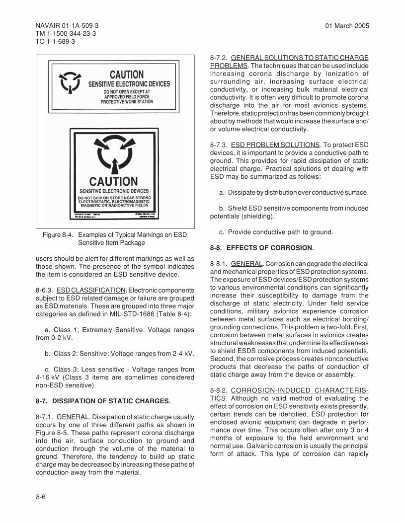
8-6
NAVAIR 01-1A-509-3TM 1-1500-344-23-3TO 1-1-689-3
01 March 2005
users should be alert for different markings as well asthose shown. The presence of the symbol indicatesthe item is considered an ESD sensitive device.
8-6.3. ESD CLASSIFICATION. Electronic componentssubject to ESD related damage or failure are groupedas ESD materials. These are grouped into three majorcategories as defined in MIL-STD-1686 (Table 8-4):
a. Class 1: Extremely Sensitive: Voltage rangesfrom 0-2 kV.
b. Class 2: Sensitive: Voltage ranges from 2-4 kV.
c. Class 3: Less sensitive - Voltage ranges from4-16 kV (Class 3 items are sometimes considerednon-ESD sensitive).
8-7. DISSIPATION OF STATIC CHARGES.
8-7.1. GENERAL. Dissipation of static charge usuallyoccurs by one of three different paths as shown inFigure 8-5. These paths represent corona dischargeinto the air, surface conduction to ground andconduction through the volume of the material toground. Therefore, the tendency to build up staticcharge may be decreased by increasing these paths ofconduction away from the material.
8-7.2. GENERAL SOLUTIONS TO STATIC CHARGEPROBLEMS. The techniques that can be used includeincreasing corona discharge by ionization ofsurrounding air, increasing surface electricalconductivity, or increasing bulk material electricalconductivity. It is often very difficult to promote coronadischarge into the air for most avionics systems.Therefore, static protection has been commonly broughtabout by methods that would increase the surface and/or volume electrical conductivity.
8-7.3. ESD PROBLEM SOLUTIONS. To protect ESDdevices, it is important to provide a conductive path toground. This provides for rapid dissipation of staticelectrical charge. Practical solutions of dealing withESD may be summarized as follows:
a. Dissipate by distribution over conductive surface.
b. Shield ESD sensitive components from inducedpotentials (shielding).
c. Provide conductive path to ground.
8-8. EFFECTS OF CORROSION.
8-8.1. GENERAL. Corrosion can degrade the electricaland mechanical properties of ESD protection systems.The exposure of ESD devices/ESD protection systemsto various environmental conditions can significantlyincrease their susceptibility to damage from thedischarge of static electricity. Under field serviceconditions, military avionics experience corrosionbetween metal surfaces such as electrical bonding/grounding connections. This problem is two-fold. First,corrosion between metal surfaces in avionics createsstructural weaknesses that undermine its effectivenessto shield ESDS components from induced potentials.Second, the corrosive process creates nonconductiveproducts that decrease the paths of conduction ofstatic charge away from the device or assembly.
8-8.2. CORROSION-INDUCED CHARACTERIS-TICS. Although no valid method of evaluating theeffect of corrosion on ESD sensitivity exists presently,certain trends can be identified. ESD protection forenclosed avionic equipment can degrade in perfor-mance over time. This occurs often after only 3 or 4months of exposure to the field environment andnormal use. Galvanic corrosion is usually the principalform of attack. This type of corrosion can rapidly
Figure 8-4. Examples of Typical Markings on ESDSensitive Item Package

8-7
NAVAIR 01-1A-509-3TM 1-1500-344-23-3
TO 1-1-689-3
01 March 2005
Table 8-4. ESD Sensitivity Categories
Vk2ot0morfsegnaregatloV-evitisneSylemertxE:1ssalC
.)sCI(stiucriCdetargetnI)sTEF(srotsisnarttceffedleifdna)SOM(rotcudnocimesedixolatemdetcetorpnU.srossecorporcimgnidulcni,secived)ISLV(noitargetnielacsegralyrevylralucitraP
.)noitasnepmoclanretnipmapo(sroticapacSOM
.A51.0nahtsselyticapactnerruchtiw)sRCS(sreifitcerdellortnocnocilistnerrucwoldna)sTEFJ(sTEFnoitcnuJ
ykttaohcSyllaicepsE.sCIdnasrotsisnart)FHV(ycneuqerfhgihyrevfoycneuqerfgnitarepomumixamevaworciM.ztrehagig1nahteromhtiwecived
.)%5.0nahtsselecnarelot(srotalugeregatlovCInoisicerP
.)%1.0nahtsselecnarelot(srotsisermlifnihtnoisicerP
.)W5.0nahtsselnoitpmusnocrewop(srotsisermlifnihtrewopwoL
.noitazillatemlevel-laudhtiwISLV
.strapIssalCgnisusdirbyH
Vk4ot2morfsegnaregatloV-evitisneS:2ssalC
.)SOMP,SOMN,SOMC(skrowtennoitcetorpDSEhtiwSOM
.)sedoidgnihctiwsnocilis(sedoidykttohcS
.ykttohcSrewopwoldna,)LCE(cigoldelpuocrettime,cigolralopibdeeps-hgiH
.)LTT-SL(cigolrotsisnarT
.)LTT-S(LTTykttohcS
.sCIraeniL
.)LR(srotsisernoisicerP
.stiucricnoitcetorpDSEhtiwsecivedISL
.strap2ssalCgnizilitusdirbyH
)evitisnesDSEnonderedisnocemitemos(Vk61ot4morfsegnaregatloV-evitisneSsseL:3ssalC
.)W1nahtsselnoitpmusnocrewop(sedoidlangisllamS
.)W5nahtsselnoitpmusnocrewop(srotsisnartlangisllamS
.)LTT-H(LTTdlohserhthgihdna,)LTD(cigolrotsisnartedoid,)LTT(cigolralopibdeepswoL
.slatsyrccirtceleozeipdnaztrauQ
destroy a bonding connection if suitable precautionsare not observed (refer to Chapter 6). Damage tobonding/grounding hardware can cause the buildup ofstatic potentials that could result in a spark discharge.Without regular maintenance, the buildup of metaloxides, absorbed atmospheric pollutants, dust, and
field debris will also contribute to ESD shieldingdegradation of the avionic enclosure. This buildupintroduces a nonconductive film between electricalcontact materials which can often severely degradeESD protection.

8-8
NAVAIR 01-1A-509-3TM 1-1500-344-23-3TO 1-1-689-3
01 March 2005
8-9. RECOMMENDED PRACTICES FOR ESDEQUIPMENT, MODULES, AND COMPONENTS.
NOTE
Some ESD control procedures involveconditions or operations that may producecorrosion. Special handling methods andmaterials must be used to prevent equipmentdamage. In case of conflict, refer to theapplicable service directives and TO 00-25-234 (Air Force only).
8-9.1. BASIC ESD PRECAUTIONS. ESD precautionsare not limited to manufacturing or component repairpersonnel only. Anyone handling, processing, or using
ESD devices must take precautionary steps. It wouldbe futile for component repair personnel to take fullprecautions, only to turn the repaired item over totechnicians who ignore all precautions andinadertvently destroy the module. Maintenancepersonnel should refer to MIL-HDBK-773, MIL-HDBK-263, and MIL-STD-1686 for more detailed descriptionsof ESD control measures.
8-9.2. ESD PACKAGING PRACTICES. Packaging ofESD items must only be done at an ESD protectiveworkstation. See Figure 8-6.
a. Packaging for electrostatic discharge protectionrequires the use of one or more of the followingmaterials:
Figure 8-5. Dissipation of Static Charges
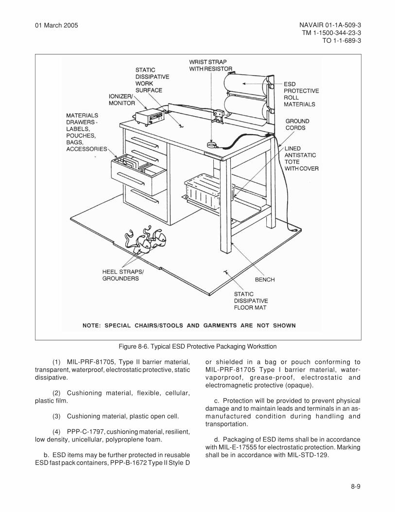
8-9
NAVAIR 01-1A-509-3TM 1-1500-344-23-3
TO 1-1-689-3
01 March 2005
(1) MIL-PRF-81705, Type II barrier material,transparent, waterproof, electrostatic protective, staticdissipative.
(2) Cushioning material, flexible, cellular,plastic film.
(3) Cushioning material, plastic open cell.
(4) PPP-C-1797, cushioning material, resilient,low density, unicellular, polyproplene foam.
b. ESD items may be further protected in reusableESD fast pack containers, PPP-B-1672 Type II Style D
or shielded in a bag or pouch conforming toMIL-PRF-81705 Type I barrier material, water-vaporproof, grease-proof, electrostatic andelectromagnetic protective (opaque).
c. Protection will be provided to prevent physicaldamage and to maintain leads and terminals in an as-manufactured condit ion during handling andtransportation.
d. Packaging of ESD items shall be in accordancewith MIL-E-17555 for electrostatic protection. Markingshall be in accordance with MIL-STD-129.
Figure 8-6. Typical ESD Protective Packaging Worksttion

8-10
NAVAIR 01-1A-509-3TM 1-1500-344-23-3TO 1-1-689-3
01 March 2005
8-9.3. ESD WORKSTATION SHOP PRACTICES.
a. Control humidity within 40% to 60% range. Humidair helps dissipate electrostatic charge.
b. Ionized air helps to bleed off static charges.
c. Prohibit prime generators (Table 8-1) andcarpeting from avionics shop areas.
d. Chairs and stools should have conductivesurfaces and should be grounded through a 250 kilohmto 1 megohm resistor to ground.
e. Trays, carriers, cushioning materials, and bagsshould be made of conductive ESD protective material.
f. Electrical equipment, tools, or soldering ironsthat come in contact with ESD devices should begrounded. Resistance to top of soldering irons shouldbe less than 20 ohms. Only ESD safe tools should beused.
g. Test equipment with exposed metal surfacesshould be grounded.
h. Personnel handling ESD devices should wearlong sleeve ESD smocks or short sleeve shirts. Prohibitmaterials such as common plastic, rubber, or nylon.
i. Personnel grounding straps should haveminimum resistance of 250 kilohms and maximum of 2megohms.
8-9.4. ESD DEVICE HANDLING PRACTICES.Damage to ESD items may occur if untrained personnelare allowed to handle ESD items when the items areoutside of an ESD protective package.
a. Protective apparel should be checked frequently,especially after cleaning, by scanning personnel withan electrostatic field meter to monitor for damagingESD voltages.
b. Be sure to attach the wrist strap (mandatory) andheel straps (if used) before handling any ESD items.
c. Avoid the presence of any nonantistatic orinsulative material near work areas. For example,styrofoam cups, plastic or masking tape, wrapping orbarrier materials, or synthetic materials.
d. Do not store or use magnetic material near workareas.
e. Do not perform stretch or shrink-wrappingoperations within the ESD-controlled work area.
f. Do not use waxes, polishes, or similar materialson floormats or tabletops. They may deposit aninsulating layer of residue. This reduces or eliminatesthe effectiveness of the floormat or tabletop. For thesame reason, the use of topical antistatic spray is notrecommended on packaging materials.
g. Sweep dust and dirt from the tabletop andfloormats as often as needed to prevent anyaccumulation. Dirt will also insulate these surfacesand make them ineffective.
h. Antistatic pouches should be used for technicalmanuals, drawings, and work instructions rather thanplain plastic pouches.
i. Ensure all containers, tools, test equipment, andfixtures are grounded before and/or during use bydirect ground or by touching a grounded surface.
j. Avoid friction producing activities near ESDdevices. For example, removing smocks, wiping feet,sliding objects over surfaces.
k. Wear cotton smock or other antistatic clothing.
l. Prohibit prime generators (Table 8-1) from ESDareas.
m. Place ESD protective material on groundedsurface to remove any charge before opening package.
n. Remove ESD item from package only aftergrounding and place item on grounded surface.
o. Use noncorrosive ESD protective conductivefoam or connect shorting clip, or bars to terminal ofESD device.
p. Perform periodic electrostatic checks to ensurework station meets specification.
8-9.5. TESTING AND/OR REPAIR PRACTICES.
a. Ensure work area, equipment, and work strapassembly are grounded.

8-11
NAVAIR 01-1A-509-3TM 1-1500-344-23-3
TO 1-1-689-3
01 March 2005
b. Attach wrist strap and place metal tools andaccessories on grounded bench surfaces.
c. Place conductive container on bench. Removecomponent or assembly from package. Removeshorting device if present. Handle components by theirbody and place on conductive work surface/test fixture.
d. Compressed gases shall not be used to coolfixtures.
e. Test through connectors or tabs only.
f. After testing, replace shorting packages andprotective packaging.
g. Do not use Simpson 260 (or equivalent)multimeter to test parts. Instead use the Fluke 8000Aor other high-impedance digital multimeter (DMM).
h. Dielectric strength tests are prohibited.
i. Only the use of anti-static type solvents is allowed.
j. Heat guns for test or curing are prohibited.
k. Drying lamps, photo spots, and thermal probesare allowed.
l. Do not remove components or assemblies fromtheir sockets with power applied.
m. Apply dc voltages prior to applying signal inputs.
n. The use of air to clean components/assembliesis prohibited unless a filtered ionizing air gun is used.
o. Do not use solvent ultrasonic cleaning bath forcomponent assemblies.
p. Device supply connections on the assemblyshould be made prior to making the ground connection.
q. Cure conformal coatings by normal ambientcuring or in an oven that contains grounding provisionsto prevent static charge buildup.
8-10.PREVENTION, TREATMENT, AND CONTROLOF CORROSION ON ESD SENSITIVE EQUIPMENT.
8-10.1. GENERAL. ESD damage to aircraft electrical/electronic devices can be caused by voltage or currentdepending on the item's composition and construction.
This damage can be caused by direct contact or by theelectrostatic field associated with other charged items.It is important to note that some modern militarycircuits are sensitive to voltages as low as 25 volts.The threshold of sensitivity or voltage level required fora human being to feel a static discharge is approximately3500 volts. Therefore, ESD devices can be damagedby maintenance personnel without their knowledge.ESD control measures must be employed to minimizethe impact of ESD damage on aircraft electrical/electronic parts, assemblies, and equipment.
8-10.2. CORROSION PREVENTIVE MAINTENANCEAND CONTROL. ESD devices must be protected fromstatic fields and/or static discharge when beingtransported, handled, or stored. The followingpreventive measures will help provide this protection.
a. Handle ESD devices only at protected workstations. These sites eliminate all sources of ESD withgood grounding techniques by electrically bonding allthe surfaces, tools, and furnishings together. Aprotective stool should also be used and any supportequipment (soldering irons, text fixtures, testequipment, lights) must be grounded.
b. ESD devices should be covered or packaged inESD-protective packaging when not being handled.
c. Conductive carriers protect static sensitivedevices by shielding them from static. These carriersare used to transport, store, and ship static sensitivedevices and should be placed on a conductive tabletop. This allows safe removal of their contents. Exampleof conductive carriers are conductive trays, boxes,and containers.
d. Shunting mechanisms short circuit all the leadsof a device. This enables the entire device to be at thesame electrical potential and prevents ESD. Shuntingmechanisms for discrete components include shortingclips, rings, and conductive foam. Conductive shuntbars are a type of shunting mechanism for printedcircuit boards (PCBs).
e. Nonconductive objects that can generate andhold different static potentials on different areas ontheir surface are poor conductors and cannot begrounded.Static neutralizing equipment should be usedto eliminate static charges on nonconductive objects.Use of an ionized air blower will neutralize staticcharge by continuously blowing a cloud of ionized airover the surface.
8-12
NAVAIR 01-1A-509-3TM 1-1500-344-23-3TO 1-1-689-3
01 March 2005
f. Personnel should not wear synthetic fiber clothes.Cotton clothes with short sleeves or a cotton smockover clothing are recommended.
g. Work areas shall be clear of static hazards suchas ordinary plastics, coffee cups, and candy wrappers.
h. Personnel shall only use uninsulated hand toolswhen working with electrostatic sensitive devices. Donot use plastic-coated tweezers, plastic lead-formingtools, or plastic solder suckers. Also, personnel shalluse only natural bristle brushes.
8-10.3. ESD PROTECTIVE SYSTEMS CORROSIONREPAIR AND TREATMENT. Corrective maintenanceof ESD protection systems depends on the type ofprotection system involved, size of the damaged area,and degree/type of corrosion. Control, treatment, andrepair measures must be employed to minimize theimpact of corrosion on ESD protection systems.Maintenance personnel should refer to Chapter 6 andthe applicable service directives for specific repairprocedures.

9-1
NAVAIR 01-1A-509-3TM 1-1500-344-23-3
TO 1-1-689-3
01 March 2005
CHAPTER 9PRESERVATION AND PACKAGING
9-1. PURPOSE. The materials, equipment, andtechniques described in this chapter are intended toassist the avionic technician at the IntermediateMaintenance Activity (IMA) in preserving, packaging,handling, and shipping avionic equipment.
9-2. PRESERVATIVES.
9-2.1. GENERAL. Surfaces and components notnormally conformal coated or painted needpreservation. Cleanliness and elimination of moistureare keys to avoiding corrosion. Since it is impossibleto guarantee a dry, moisture-free environment,preservation of equipment is essential. In today'savionic systems, miniaturization has resulted inmicrominiature circuits no longer than a pencil eraser.The slightest amount of corrosion can cause a wholesystem to fail. Preservation has become an essentialpart of the repair and maintenance of avionic systems.
9-2.2. WHY PRESERVE.
a. To protect nonmoving parts by filling air spaces,displacing water, and providing coatings.
b. To protect components such as hinges, controlcables, gears, linkages, or bearings, from wear byproviding lubrication.
c. To protect nonoperating or idle equipment.
9-2.3. WHEN TO PRESERVE. Preservatives shouldalways be used:
a. After avionic cleaning.
b. On avionic equipment prior to shipment.
c. On equipment or components that arenonoperating or idle (including those awaiting parts).
d. Whenever access is achieved to parts normallyinaccessible for inspection without disassembly andinspection.
e. Whenever paint films in difficult-to-protect areasrequire additional preservation.
f. After immersion or exposure to fresh water, saltwater, or fire extinguishing agents.
g. Whenever the corrosion protection system hasfailed in service.
9-2.4. WHAT TO PRESERVE. Preservatives shouldbe used only where their application and maintenancewill not hamper circuit or component operation.Components that do not require preservation are listedin paragraph 9-2.5. Most preservatives form anonconductive film that acts to insulate two matingsurfaces. For example, preservative on a relay's matingcontacts will degrade operation of the relay. Eachpiece of avionic equipment should be inspected. Withthe assistance of the applicable service directives,areas requiring preservation should be noted andpreserved on a scheduled basis. The following itemsmay require preservation on a scheduled basis:
a. Hinges and door latches.
b. Electrical connectors and receptacles.
c. Shock mounts, rigid mounts, and associatedbrackets.
d. Any dissimilar metals not otherwise preserved.
e. Antenna mounts, brackets, hardware, andhousings.
f. Fasteners, screws, nuts, and bolts.
g. Terminal boards, bus bars, and junction boxes.
h. Equipment lids on the interior or exterior ofequipment that are susceptible to moisture.
i. Solder joints not otherwise conformal coated.
j. Unpainted mounting brackets, equipment racks,and shelving.
k. Unpainted equipment covers, lids, and chassis.
l. External and internal surfaces of coaxialconnectors.
m. External surfaces of cooling system joints.
n. Grounding straps and wires.
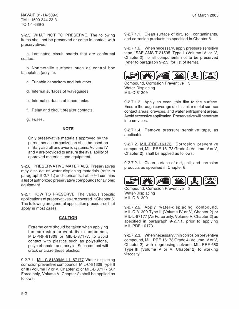
9-2
NAVAIR 01-1A-509-3TM 1-1500-344-23-3TO 1-1-689-3
01 March 2005
9-2.5. WHAT NOT TO PRESERVE. The followingitems shall not be preserved or come in contact withpreservatives:
a. Laminated circuit boards that are conformalcoated.
b. Nonmetallic surfaces such as control boxfaceplates (acrylic).
c. Tunable capacitors and inductors.
d. Internal surfaces of waveguides.
e. Internal surfaces of tuned tanks.
f. Relay and circuit breaker contacts.
g. Fuses.
NOTE
Only preservative materials approved by theparent service organization shall be used onmilitary aircraft and avionic systems. Volume IVand V are provided to ensure the availability ofapproved materials and equipment.
9-2.6. PRESERVATIVE MATERIALS. Preservativesmay also act as water-displacing materials (refer toparagraph 9-2.7.1.) and lubricants. Table 9-1 containsa list of authorized preservative compounds for avionicequipment.
9-2.7. HOW TO PRESERVE. The various specificapplications of preservatives are covered in Chapter 6.The following are general application procedures thatapply in most cases.
CAUTION
Extreme care should be taken when applyingthe corrosion preventative compounds,MIL-PRF-81309 or MIL-L-87177, to avoidcontact with plastics such as polysulfone,polycarbonate, and acrylic. Such contact willcrack or craze these plastics.
9-2.7.1. MIL-C-81309/MIL-L-87177. Water-displacingcorrosion preventive compounds, MIL-C-81309 Type IIor III (Volume IV or V, Chapter 2) or MIL-L-87177 (AirForce only, Volume V, Chapter 2) shall be applied asfollows:
9-2.7.1.1. Clean surface of dirt, soil, contaminants,and corrosion products as specified in Chapter 6.
9-2.7.1.2. When necessary, apply pressure sensitivetape, SAE-AMS-T-21595 Type I (Volume IV or V,Chapter 2), to all components not to be preserved(refer to paragraph 9-2.5. for list of items).
Compound, Corrosion Preventive 3Water-DisplacingMIL-C-81309
9-2.7.1.3. Apply an even, thin film to the surface.Ensure thorough coverage of dissimilar metal surfacecontact areas, crevices, and water entrapment areas.Avoid excessive application. Preservative will penetrateinto crevices.
9-2.7.1.4. Remove pressure sensitive tape, asapplicable.
9-2.7.2. MIL-PRF-16173. Corrosion preventivecompound, MIL-PRF-16173 Grade 4 (Volume IV or V,Chapter 2), shall be applied as follows:
9-2.7.2.1. Clean surface of dirt, soil, and corrosionproducts as specified in Chapter 6.
Compound, Corrosion Preventive 3Water-DisplacingMIL-C-81309
9-2.7.2.2. Apply water-displacing compound,MIL-C-81309 Type II (Volume IV or V, Chapter 2) orMIL-L-87177 (Air Force only, Volume V, Chapter 2) asspecified in paragraph 9-2.7.1. prior to applyingMIL-PRF-16173.
9-2.7.2.3. When necessary, thin corrosion preventivecompound, MIL-PRF-16173 Grade 4 (Volume IV or V,Chapter 2) with degreasing solvent, MIL-PRF-680Type III (Volume IV or V, Chapter 2) to workingviscosity.
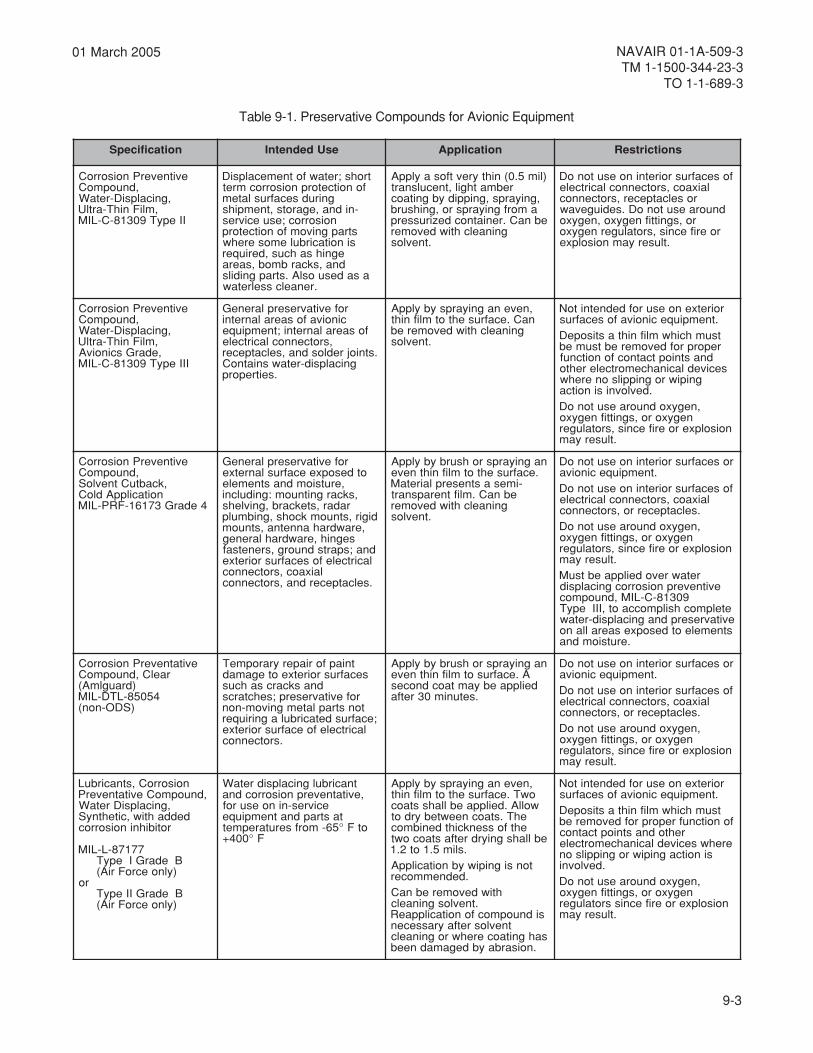
9-3
NAVAIR 01-1A-509-3TM 1-1500-344-23-3
TO 1-1-689-3
01 March 2005
noitacificepS esUdednetnI noitacilppA snoitcirtseR
evitneverPnoisorroC,dnuopmoC
,gnicalpsiD-retaW,mliFnihT-artlU
IIepyT90318-C-LIM
trohs;retawfotnemecalpsiDfonoitcetorpnoisorrocmret
gnirudsecafruslatem-nidna,egarots,tnempihs
noisorroc;esuecivresstrapgnivomfonoitcetorpsinoitacirbulemoserehw
egnihsahcus,deriuqerdna,skcarbmob,saera
asadesuoslA.strapgnidils.renaelcsselretaw
)lim5.0(nihtyrevtfosaylppArebmathgil,tneculsnart
,gniyarps,gnippidybgnitaocamorfgniyarpsro,gnihsurb
ebnaC.reniatnocdezirusserpgninaelchtiwdevomer
.tnevlos
fosecafrusroiretninoesutonoDlaixaoc,srotcennoclacirtcele
roselcatpecer,srotcennocdnuoraesutonoD.sediugevaw
ro,sgnittifnegyxo,negyxoroerifecnis,srotalugernegyxo
.tluseryamnoisolpxe
evitneverPnoisorroC,dnuopmoC
,gnicalpsiD-retaW,mliFnihT-artlU,edarGscinoivA
IIIepyT90318-C-LIM
rofevitavreserplareneGcinoivafosaeralanretni
fosaeralanretni;tnempiuqe,srotcennoclacirtcele
.stniojredlosdna,selcatpecergnicalpsid-retawsniatnoC
.seitreporp
,nevenagniyarpsybylppAnaC.ecafrusehtotmlifniht
gninaelchtiwdevomereb.tnevlos
roiretxenoesurofdednetnitoN.tnempiuqecinoivafosecafrustsumhcihwmlifnihtastisopeDreporprofdevomerebtsumeb
dnastnioptcatnocfonoitcnufsecivedlacinahcemortcelerehto
gnipiwrognippilsonerehw.devlovnisinoitca
,negyxodnuoraesutonoDnegyxoro,sgnittifnegyxo
noisolpxeroerifecnis,srotaluger.tluseryam
evitneverPnoisorroC,dnuopmoC
,kcabtuCtnevloSnoitacilppAdloC
4edarG37161-FRP-LIM
rofevitavreserplareneGotdesopxeecafruslanretxe
,erutsiomdnastnemele,skcargnitnuom:gnidulcni
radar,stekcarb,gnivlehsdigir,stnuomkcohs,gnibmulp
,erawdrahannetna,stnuomsegnih,erawdrahlareneg
dna;spartsdnuorg,srenetsaflacirtcelefosecafrusroiretxe
laixaoc,srotcennoc.selcatpecerdna,srotcennoc
nagniyarpsrohsurbybylppA.ecafrusehtotmlifnihtneve
-imesastneserplairetaMebnaC.mliftnerapsnart
gninaelchtiwdevomer.tnevlos
rosecafrusroiretninoesutonoD.tnempiuqecinoiva
fosecafrusroiretninoesutonoDlaixaoc,srotcennoclacirtcele
.selcatpecerro,srotcennoc,negyxodnuoraesutonoD
negyxoro,sgnittifnegyxonoisolpxeroerifecnis,srotaluger
.tluseryamretawrevodeilppaebtsuM
evitneverpnoisorrocgnicalpsid90318-C-LIM,dnuopmoc
etelpmochsilpmoccaot,IIIepyTevitavreserpdnagnicalpsid-retawstnemeleotdesopxesaerallano
.erutsiomdna
evitatneverPnoisorroCraelC,dnuopmoC
)drauglmA(45058-LTD-LIM
)SDO-non(
tniapforiaperyraropmeTsecafrusroiretxeotegamad
dnaskcarcsahcusrofevitavreserp;sehctarcstonstraplatemgnivom-non
;ecafrusdetacirbulagniriuqerlacirtcelefoecafrusroiretxe
.srotcennoc
nagniyarpsrohsurbybylppAA.ecafrusotmlifnihtneve
deilppaebyamtaocdnoces.setunim03retfa
rosecafrusroiretninoesutonoD.tnempiuqecinoiva
fosecafrusroiretninoesutonoDlaixaoc,srotcennoclacirtcele
.selcatpecerro,srotcennoc,negyxodnuoraesutonoD
negyxoro,sgnittifnegyxonoisolpxeroerifecnis,srotaluger
.tluseryam
noisorroC,stnacirbuL,dnuopmoCevitatneverP
,gnicalpsiDretaWdeddahtiw,citehtnyS
rotibihninoisorroc
77178-L-LIMBedarGIepyT)ylnoecroFriA(
roBedarGIIepyT)ylnoecroFriA(
tnacirbulgnicalpsidretaW,evitatneverpnoisorrocdna
ecivres-ninoesuroftastrapdnatnempiuqe
otF°56-morfserutarepmetF°004+
,nevenagniyarpsybylppAowT.ecafrusehtotmlifnihtwollA.deilppaebllahsstaoc
ehT.staocneewtebyrdotehtfossenkcihtdenibmoc
ebllahsgniyrdretfastaocowt.slim5.1ot2.1
tonsignipiwybnoitacilppA.dednemmocer
htiwdevomerebnaC.tnevlosgninaelc
sidnuopmocfonoitacilppaeRtnevlosretfayrassecen
sahgnitaocerehwrogninaelc.noisarbaybdegamadneeb
roiretxenoesurofdednetnitoN.tnempiuqecinoivafosecafrustsumhcihwmlifnihtastisopeD
fonoitcnufreporprofdevomerebrehtodnastnioptcatnoc
erehwsecivedlacinahcemortcelesinoitcagnipiwrognippilson
.devlovni,negyxodnuoraesutonoD
negyxoro,sgnittifnegyxonoisolpxeroerifecnissrotaluger
.tluseryam
Table 9-1. Preservative Compounds for Avionic Equipment
9-4
NAVAIR 01-1A-509-3TM 1-1500-344-23-3TO 1-1-689-3
01 March 2005
Compound, Corrosion Preventive 8MIL-PRF-16173
9-2.7.2.4. Apply MIL-PRF-16173 Grade 4 with brush(Volume IV or V, Chapter 3), or spray an even, thin filmto non-moving external areas.
9-2.7.3. Fasteners. Dip screws or fasteners inpreservative and install. Where disassembly is frequent,use MIL-L-63460 or MIL-C-81309 Type II (Air Forcemay also use MIL-L-87177). When infrequent, useMIL-C-16173 Grade 4 for long term protection.
9-3. PACKAGING, HANDLING, AND STORAGE.
9-3.1. GENERAL. An avionic corrosion controlprogram must include procedures for packaging,handling, and storage of avionic equipment andcomponents. Preventive maintenance techniques arerendered useless if these procedures are not followed.Materials used to package, handle, or store avionicequipment must be compatible with the equipmentand environment. Refer to MIL-STD-2073/1,MIL-E-17555, NAVSUP 484 (Navy), TO 00-85-3 (AirForce), and AR 746-1 (Army) for additional informationon packaging and preservation.
NOTE
Some avionic equipment contains ESDSmodules or components. Maintenancepersonnel should have ESD device handlingprocedures established by the applicableservice directives. Failure to do so willjeopardize ESD device/mission integrity. Referto Chapter 8 to avoid confl ict withrecommended practices for ESD equipment,modules, and components.
9-3.2. MAINTENANCE ACTIVITIES COMPLIANCE.Organizational/Unit and Intermediate MaintenanceActivities shall comply with the following:
9-3.2.1. Use only metal or preserved wooden shelvesfor storing avionic equipment and components.
9-3.2.2. Provide polyethylene foam, A-A-59135 orA-A-59136 (Volume IV or V, Chapter 2), 1/2 inch thick,as cushioning for equipment on shelves, or pallets. Donot use horse hair, sponge-rubber, or similar materials.
NOTE
Refer to NAVAIR 01-1A-505 (Navy), TO 1-1A-14 (Air Force), or TM 55-1500-323-24 (Army)for information on electrical connector caps.
9-3.2.3. Plastic or metal caps shall be used forelectrical connector protection, as specified inparagraphs 9-3.4. and 9-3.5.
CAUTION
Use only special handling/shipping containersfor protection of avionics from shock.
9-3.2.4. Use cushioning material, cellular plastic film(bubble wrap), PPP-C-795 Class 1 (Volume IV or V,Chapter 2), for short term protection of equipmentfrom handling and shock.
9-3.2.5. Use plastic bags, A-A-1799 (Volume IV or V,Chapter 2), for short term protection of uninstalledsmall components and microminiature PCBs againstmoisture and contamination.
9-3.2.6. Use unicellular polypropylene packagingfoam, PPP-C-1797 (Volume IV or V, Chapter 2), andwater vapor proof packaging material, MIL-PRF-131Class 1 (Volume IV or V, Chapter 2), for long-termprotection of miniature/microminiature circuitcomponents, laminated circuit boards, and criticalavionic components against moisture andcontamination.
9-3.2.7. Comply with the requirements ofMIL-STD-2073/1, MIL-E-17555, NAVSUP 484 (Navy),TO 00-85-3 (Air Force), or AR 746-1(Army) whenshipping avionic equipment by air/surface.
9-3.2.8. For equipment requiring ESD protection, referto Chapter 8.
9-3.3. HANDLING. Damage has occurred to avionicequipment because of incorrect/rough handlingbetween repair shops and incorrect packagingmethods. The best method of avoiding handlingdamage when transporting equipment is through theuse of cushioning material (bubble wrap), PPP-C-795Class 1 (Volume IV or V, Chapter 2). Bubble wrap isprimarily used to absorb shock and is not intended asa preservation material. Packaging materials mayabsorb moisture through "breathing" as pressurechanges occur. Bubble wrap should be placed aroundthe component in both directions leaving the corners
9-5
NAVAIR 01-1A-509-3TM 1-1500-344-23-3
TO 1-1-689-3
01 March 2005
open to avoid condensation. Use masking tape,SAE-AMS-T-21595 (Volume IV or V, Chapter 2) forsecuring bubble wrap. Use preservation and sealingtape, SAE-AMS-T-22085 Type II (Volume IV or V,Chapter 2) or masking tape, SAE-AMS-T-23397(Volume IV or V, Chapter 2) as alternates.
9-3.4. PACKAGING AND STORAGE. Althoughpackaging is a function of the Supply Department,many times avionic equipment is packaged bymaintenance personnel. This is for shipping betweenshops, operating activities, or ships prior to/duringdeployments. Packaging methods are an importantconsideration because the time equipment is in transitcould be lengthy.
9-3.4.1. Proper packaging should include provisionsfor the length of time equipment will be in storage.Equipment should be packaged for long-term protectionif the length of storage time is uncertain.
9-3.4.2. Local packaging of avionic equipment andcomponents shall apply the following procedures:
9-3.4.2.1. Plastic bags, A-A-1799 (Volume IV or V,Chapter 2), provide adequate protection againstmoisture and contamination for short-term, temporarystorage. These bags shall be used during maintenanceor repair operations of laminated circuit boards andsmall electrical/electronic components.
9-3.4.2.2. Barrier Material, Water Vapor Proof,MIL-PRF-131 Class 1 (Volume IV or V, Chapter 2),provides excellent protection against moisture andcontamination. It is used during equipmenttransportation and long-term storage under all weatherconditions. This material shall be used for long-termpackaging of miniature/microminiature circuitcomponents, laminated circuit boards, and other criticalavionic components. Barrier Material, Water VaporProof, MIL-PRF-131 Class 1, shall be sealed withSealing Machine, Electric Jaw (Volume IV or V,Chapter 3).
9-3.4.2.3. Unicellular polypropylene packaging foam,PPP-C-1797 (Volume IV or V, Chapter 2), is used forprotection against shock and moisture. If protectionagainst shock and handling is required in conjunctionwith Plastic Bags, A-A-1799 (Volume IV or V,Chapter 2), or Barrier Material, Water Vapor Proof,MIL-PRF-131 (Volume IV or V, Chapter 2), use theunicellular polypropylene packaging foam held in place
by pressure sensitive tape, SAE-AMS-T-22085 Type II(Volume IV or V, Chapter 2).
9-3.4.3. For equipment requiring ESD protection referto Chapter 8.
9-3.5. ELECTRICAL CONNECTOR AND WAVE-GUIDE CAPS. The use of plastic caps hinders con-tamination of equipment from airborne particles presentin repair shops/supply spaces.
9-3.5.1. During Organizational/Unit levelmaintenance, the plastic cap can become foreignobject debris (FOD) in an aircraft. In aircraft withengine or equipment removed for inspection ormaintenance, many electrical connectors are exposed.Military standard metal covers shall be used in lieu ofplastic covers in these cases.
CAUTION
No tape other than pressure sensitive tape,SAE-AMS-T-22085 Type II, is authorized foruse on wave guides or electrical connectors.Air Force only refer to TO 00-25-234 for tapingof wave guide connectors.
9-3.5.2. If military standard metal covers are notavailable, cap-off electrical connectors or waveguideswith pressure sensitive tape, SAE-AMS-T-22085Type II (Volume IV or V, Chapter 2). In no case will anyother tape be used to seal or cap-off electricalconnectors.
9-3.6. DESICCANTS. Desiccants are normallypackaged in equipment crated for shipment or storage.In some cases, the desiccants are placed in systemsaboard aircraft. Desiccant, MIL-D-3464 Type II(Volume IV or V, Chapter 2) is used to absorb moistureand lower the relative humidity when placed in asealed container.
9-3.6.1. Desiccants may be ineffective for the followingreasons:
a. Moisture may condense as water if the desiccantbecomes saturated.
b. Desiccant is not in the right location.
c. Rapid change in temperature may produceprecipitation before the desiccant can react.

9-6
NAVAIR 01-1A-509-3TM 1-1500-344-23-3TO 1-1-689-3
01 March 2005
d. Not enough desiccant is present.
CAUTION
Do not use loose desiccant in packaging ofavionic equipment. The use of loose desiccantmay cause damage to equipment.
9-3.6.2. The following considerations apply todesiccants:
a. Desiccants shall be in unruptured bags of sturdyconstruction.
b. Bags will be secured to prevent movement.
c. Desiccant bags shall not be placed on, norpermitted to come in contact with, unprotected surfaces.
d. Desiccants should be reactivated prior to reuse.
e. Do not remove desiccant from wrap unless readyfor use.
9.3.6.3. If a desiccant bag should break open duringtransit, clean the avionic equipment immediately. Donot turn moving parts any more than absolutelynecessary until all desiccant particles have beenremoved. Work out the desiccant particles with a brushand not more than 10 psi dry air pressure. Use AcidBrush, A-A-289 style opt. (Volume IV or V, Chapter 3),or Artist's Brush, (Volume IV or V, Chapter 3) for thispurpose. An alternate method is the use of a brush andvacuum cleaner (Volume IV or V, Chapter 3).
CAUTION
Do not place humidity indicator in direct contactwith metal. Chemicals used in the indicatormay cause corrosion.
9-3.7. HUMIDITY INDICATORS. Humidity indicators,MIL-I-8835 (Volume IV or V, Chapter 2), shall be placedin containers with desiccants. A humidity indicator isused to determine if a desiccant is sufficiently active tomaintain an acceptable relative humidity. Navy shallrefer to NAVAIR 15-01-500 for instructions on installinghumidity indicators.
10-1
NAVAIR 01-1A-509-3TM 1-1500-344-23-3
TO 1-1-689-3
01 March 2005
CHAPTER 10EMERGENCY PROCEDURES
10-1. GENERAL.
10-1.1. This chapter describes emergency corrosioncleaning and treatment procedures to be followedafter aircraft accidents. Particular incidents may involveexposure to gross amounts of salt water, fireextinguishing agents, industrial pollutants, soot, orsmoke. It is imperative that immediate action be takento remove, clean, dry, and preserve all affected avionicequipment. When removal of this equipment isimpractical, cleaning, drying, and preserving effortsshall be performed aboard the aircraft.
10-1.2. Steps outlined in the emergency proceduresare normally used only to prevent further corrosiondamage. Affected equipment will usually require furthertreatment at a higher level of maintenance. Treatedequipment that is of questionable operating statusshould be forwarded to the nearest IntermediateMaintenance Activity (IMA). This will enable furthercleaning, drying, preservation, inspection, andoperational check. Equipment damaged beyond thecapability of local repair shall be cleaned, preserved,packaged, and forwarded to the appropriate repairactivity. Equipment shall be screened and repaired inaccordance with the applicable service directives.
10-2. EMERGENCY RECLAMATION TEAM.
NOTE
In cases involving aircraft accidents,permission must be obtained from seniormember of the accident investigation boardprior to start of emergency procedures.
10-2.1. GOAL OF EMERGENCY RECLAMATIONTEAM. The primary goal of the emergency reclamationteam is to accomplish the necessary salvageoperations after an aircraft accident. This includes theassociated corrosion control efforts.
10-2.2. EMERGENCY RECLAMATION TEAMORGANIZATION. Each reporting custodian shalldesignate a Corrosion Control Officer, whose dutiesinclude organizing and supervising the emergencyreclamation team. Maintenance control will direct theteam to accomplish salvage operations or corrosion
control action. The size and composition of the teamdepends on the urgency of the situation and/orworkload. Additional personnel, if required, will beselected and placed under the direction of the CorrosionControl Officer. In case of fire damage, the MaterialsEngineering Division of the cognizant activity must becontacted. This group will determine the effects of heator excessive salt water contamination prior to continueduse/repair of affected parts.
10-3. EMERGENCY PREPARATIONS.
10-3.1. REMOVAL PRIORITY. Emergencypreparations shall include the preparation of prioritylists for removal of equipment, emergency reclamationteam planning, tools, materials, and equipmentavailability. For more specific information on removalpriority of avionic equipment, refer to Volume II of thismanual (Navy and Army) or TO 1-1-691 (Air Force).
CAUTION
Magnesium parts are particularly susceptibleto corrosion attack while exposed to salt water,water immersion, or fire extinguishing agents.Avionic equipment known to contain magnesiumcomponents shall be given high priorityemergency procedures. The procedure foridentification of magnesium is contained inparagraph 5-2.3.
10-3.2. EQUIPMENT REPLACEMENT. Variousdegrees of damage will be encountered whenequipment is exposed to salt water, water immersion,or fire extinguishing agents. Each maintenance officershall prepare or have access to a list of equipmentindicating removal priority. This information shall beused to make the decision to retain or replaceequipment. Special attention shall be given to theavailability of replacement parts, capability of the repairfacility, and importance of continuing flight operations.In the event of an aircraft mishap, reclamation of theaircraft is secondary to preserving evidence necessaryto support the Accident Investigation Board andassociated engineering investigations. Emergencyprocedures shall not commence until authorized bythe Accident Investigation Board.
10-2
NAVAIR 01-1A-509-3TM 1-1500-344-23-3TO 1-1-689-3
01 March 2005
10-3.3. REQUIRED TOOLS, MATERIALS, ANDEQUIPMENT. Immediate availability of the necessarycorrosion control tools, materials, and equipment willsignificantly aid in reducing further damage. Refer tomaterial and equipment lists in Volume IV and V. Certainspecial items of equipment which will be useful andshould be readily available are:
a. Dry Nitrogen Source.
b. Dry Air Source.
c. Vented Drying Oven, Forced Air. (Volume IVand V, Chapter 3)
d. Vented Drying Ovens, Bulb Type. (Volume IVand V, Chapter 3)
e. Hot Air Blowers. (Volume IV and V, Chapter 3)
f. Pump, Backpack. (Volume IV and V, Chapter 3)
g. Clean Empty 55 Gallon Drums.
10-3.4. PRODUCTION PLANNING. Wheneverpossible, all salvageable components of the aircraftshall be treated simultaneously. The most experiencedpersonnel available shall be assigned to disassembleand process the aircraft. This will minimize damageand ensure that the work is accomplished in a thoroughand competent manner. Whenever possible,examination and evaluation personnel shall beassigned to work with the disassembly and preservationcrew. This enables unreclaimable items to be scrappedimmediately and ensures that only areas exposed tocorrosive agents are disassembled and treated. Thetime saved by this procedure may be utilized inpreserving salvageable components.
10-4. EMERGENCY CLEANING PROCEDURES.
CAUTION
Cleaning compounds and solvents identifiedin Volume IV and V, Chapter 2, may react withsome encapsulants or plastics used to form fireharness tubing, wire coatings, conformalcoatings, gaskets, or seals. Test on a smallarea for softening or other adverse reactionsprior to general application. Refer to Table 2-4for further restrictions on these materials.
10-4.1. GENERAL. Where possible, the primarymethod of emergency cleaning (paragraph 10-4.2)shall be used. One of the alternate methods ofemergency cleaning shall be used when a sufficientquantity of fresh water is not available.
10-4.2. PRIMARY CLEANING METHOD. The primarymethod for removing salt water and fire extinguishingagents shall be used when a sufficient quantity of freshwater is available.
a. Flush all internal and external areas with clean,fresh water. Whenever possible, units or componentsthat have been removed should be immersed andflushed thoroughly in clean, fresh water. A 55-gallondrum may be used for this purpose. Tilt the equipmentback and forth to aid in draining off excess water
WARNING
Compressed air used for drying can createairborne particles that may enter the eyes.Pressure shall not exceed 10 psi. Eye protectionis required.
b. Blow off excess water with not more than 10 psiair pressure or dry nitrogen. Deflect jet of air off interior,back, and sides of enclosures to diffuse.
Compound, Aircraft Cleaning 4MIL-PRF-85570
c. (N) (A) If any evidence of salt or fire extinguishingagents remain, a second cleaning action should beinitiated, using a solution of one part Aircraft CleaningCompound, MIL-PRF-85570 Type II (Volume IV,Chapter 2), to ten parts of distilled water. Scrub theaffected areas with the solution. Flush thoroughly withfresh water and drain excess. The equipment may beimmersed in fresh water to aid in removing hiddencontaminants. Tilt the equipment back and forth to aidin draining excess water.
d. (AF) If any evidence of salt or fire extinguishingagents remain, a second cleaning action should beinitiated, using a solution of one part Aircraft CleaningCompound, MIL-PRF-87937 Type II or IV (Volume V,Chapter 2), to ten parts of distilled water. Scrub theaffected areas with the solution. Flush thoroughly withfresh water and drain excess. The equipment may be

10-3
NAVAIR 01-1A-509-3TM 1-1500-344-23-3
TO 1-1-689-3
01 March 2005
immersed in fresh water to aid in removing hiddencontaminants. Tilt the equipment back and forth to aidin draining excess water.
e. Blow off excess water as specified in step b.
10-4.3. ALTERNATE CLEANING METHODS.
10-4.3.1. Solvent Method.
Solvent, Degreasing 7MIL-PRF-680
a. If soil or soot remain on external equipmentchassis, scrub the affected areas using Paint Brush(Volume IV or V, Chapter 3) and Degreasing Solvent,MIL-PRF-680 Type III or Cleaning Solvent (Volume IVor V, Chapter 2).
b. Collect excess solvent and dispose as hazardouswaste.
c. Clean as specified in paragraph 10-4.2. steps c ord, and e.
10-4.3.2. Aircraft Cleaning Compound Method.
Compound, Aircraft Cleaning 4MIL-PRF-85570
a. (N) (A) Dip a cloth or brush in mixture of one partAircraft Cleaning Compound, MIL-PRF-85570 Type II(Volume IV, Chapter 2), in nine parts water. Rub overaffected exterior and interior areas until contaminantsbecome intermixed or emulsified. Wipe off thoroughlywith Cleaning Cloth, CCC-C-46 Class 7(Volume IV,Chapter 2), removing both contaminant and cleaner.
b. (AF) Dip a cloth or brush in mixture of one partAircraft Cleaning Compound, MIL-PRF-87937 Type IIor IV (Volume V, Chapter 2), in nine parts water. Rubover affected exterior and interior areas untilcontaminants become intermixed or emulsified. Wipeoff thoroughly with Cleaning Cloth, CCC-C-46 Class 7(Volume V, Chapter 2), removing both contaminant andcleaner.
WARNING
Compressed air used for drying can createairborne particles that may enter the eyes.Pressure shall not exceed 10 psi. Eye protectionis required.
c. Blow off excess solution with not more than 10 psidry air pressure or dry nitrogen. Deflect jet of air offinterior, back, and sides of enclosure to diffuse.
10-4.3.3. Water-Displacing Method. The waterdisplacing method is to be used as a last resort and onlyfor temporary preservation prior to thorough cleaning.Water-Displacing Corrosion Preventive Compound,Ultra-Thin Film, MIL-C-81309, or Water-DisplacingLubricant and Corrosion Preventive Compound,MIL-L-87177 Type I or II Grade B (AF only), will deposita nonconductive film. This film must be removed forproper function of contact points and otherelectromechanical devices where no slipping or wipingaction is involved. Tag equipment with appropriatemarking and indicate application of the corrosionpreventive compound. This compound is easily removedwith Degreasing Solvent, MIL-PRF-680 Type III.
WARNING
Compressed air used for drying can createairborne particles that may enter the eyes.Pressure shall not exceed 10 psi. Eye protectionis required.
a. Blow off excess water with not more than 10 psidry air pressure or dry nitrogen. Deflect jet of air offinterior, back, and sides of enclosures to diffuse.
Compound, Corrosion Preventative 3Water-DisplacingMIL-C-81309
b. (N) (A) Totally immerse equipment in a 55-gallondrum of Water-Displacing Corrosion PreventiveCompound, Ultra-Thin Film, MIL-C-81309 Type II(Volume IV, Chapter 2). If immersion is not possible,spray, brush, or wipe the interior and exterior ofequipment with water-displacing corrosion preventivecompound.

10-4
NAVAIR 01-1A-509-3TM 1-1500-344-23-3TO 1-1-689-3
01 March 2005
c. (AF) Totally immerse equipment in a 55-gallondrum of Water-Displacing Corrosion PreventiveCompound, Ultra-Thin Film, MIL-C-81309 Type II, orWater-Displacing Lubricant and Corrosion PreventiveCompound MIL-L-87177 Type I or II Grade B (Volume V,Chapter 2). If immersion is not possible, spray, brush, orwipe the interior and exterior of equipment withwater-displacing corrosion preventive compound.
10-4.4. REMOVING PURPLE K POWDER (O-D-1407,POTASSIUM BICARBONATE) OR OTHER DRYCHEMICAL FIRE EXTINGUISHING AGENTS. Toremove powder, proceed as follows:
a. If the surplus can be removed by vacuum cleaning,do so; otherwise, use the following rinse procedure.
b. Use a soft bristle brush and air pressure notgreater than 10 psi to dislodge contaminants betweenclose-fitting components.
c. Vacuum clean again.
Compound, Aircraft Cleaning 4MIL-PRF-85570
d. (N) (A) Remove the residual film of dry powderadhering to the surface by wiping, brushing, or sprayingwith a solution of one part aircraft cleaning compound,MIL-PRF-85570 Type II (Volume IV, Chapter 2), in nineparts of water.
e. (AF) Remove the residual film of dry powderadhering to the surface by wiping, brushing, or sprayingwith a solution of one part of MIL-PRF-87937 Type IV orMIL-PRF-85570 Type II aircraft cleaning compound(Volume V, Chapter 2), in nine parts of water.
f. Rinse thoroughly with fresh water.
g. Dry with cloths or paper towels, or blow dry withair pressure not greater than 10 psi.
Compound, Corrosion Preventative 3Water-DisplacingMIL-C-81309
h. (N)(A) Liberally apply water displacing CPC,MIL-C-81309 Type II (Volume IV, Chapter 2), to affectedareas.
i. (AF) Apply a liberal amount of MIL-C-81309Type II, or MIL-L-87177 Type I or II Grade B, waterdisplacing CPC (Volume V, Chapter 2) to the affectedarea.
j. Enter a notation defining areas and componentsthat have been exposed to residue from burned materialsand fire extinguishing agent in the appropriate aircraft,missile, or equipment forms, with a requirement for aspecial inspection for corrosion prone areas orcomponents at a specified future time to determine ifany corrosion has occurred.
10-4.5. REMOVING MIL-F-24385, AQUEOUS FILMFORMING FOAM (AFFF). To remove residues of saltwater solutions of AFFF fire extinguishing agent, proceedwith steps a. through j. below. To remove residues offresh water solutions of AFFF, use the same procedurebut omit steps b. through d.
NOTE
The following procedure applies to AFFF andsalt water mixture normally used aboard ship.AFFF and fresh water mixtures usually do notpresent a corrosion problem. However, cleanupof residues after a fire is required for corrosionprevention.
a. Flush all affected areas with fresh, clean waterwhile draining. Whenever possible, units or componentswhich have been removed should be immersed in freshwater and then flushed thoroughly with fresh, cleanwater. Drain away the water.
b. Mix a solution of one pint of AFFF fire extinguishingagent (MIL-F-24385) in 10 gallons of fresh water.

10-5
NAVAIR 01-1A-509-3TM 1-1500-344-23-3
TO 1-1-689-3
01 March 2005
c. Apply solution to affected areas using one of thefollowing methods:
(1) Use a foam generator, solvent wash gun,backpack, or other type of spray equipment.
(2) Use aircraft washing kit, sponges, or low lintcloths, or pour solution directly over affected areas iffoaming generator is not available.
d. Keep affected areas wet with AFFF solution for3 to 5 minutes.
Compound, Aircraft Cleaning 4MIL-PRF-85570
e. (N) (A) Clean surfaces with a solution of one partaircraft cleaning compound, MIL-PRF-85570 Type II(Volume IV, Chapter 2), in nine parts of water. Scrubaffected areas and rinse with clean, fresh water. Drainaway excess water.
f. (AF) Clean surfaces with a solution of one partMIL-PRF-87937 Type IV, or MIL-PRF-85570 Type II,aircraft cleaning compound (Volume V, Chapter 2), innine parts of water. Scrub affected areas and rinse withclean, fresh water. Drain away excess water.
g. Dry with cloths, paper towels, or air pressure notgreater than 10 psi.
Compound, Corrosion Preventative 3Water-DisplacingMIL-C-81309
h. (N) (A) Apply water displacing CPC, MIL-C-81309Type III (Volume IV, Chapter 2) to all avionic componentsand electrical connectors. Liberally apply waterdisplacing CPC, MIL-C-81309 Type II (Volume IV,Chapter 2), to all other areas that cannot be properlydrained or recesses which are difficult to reach.
i. (AF) Apply MIL-C-81309 Type III or MIL-L-87177Type I or II Grade B (Volume V, Chapter 2), waterdisplacing CPC to all avionic components and electricalconnectors. Apply a liberal amount of MIL-C-81309
Type II or MIL-L-87177 Type I or II Grade B waterdisplacing CPC to all other areas that cannot be properlydrained or contain recesses which are difficult toreach.
j. Enter a notation defining areas and componentsthat have been exposed to residue from burned materialsand fire extinguishing agent in the appropriate aircraft,missile, or equipment forms, with a requirement for aspecial inspection for corrosion prone areas orcomponents at a specified future time to determine ifany corrosion has occurred.
10-4.6. REMOVAL OF CARBON DIOXIDE (CO2),HFC-125, OR HALON FIRE EXTINGUISHINGAAGENTS.
NOTE
Carbon dioxide, HFC-125, or Halon fireextinguishing agents will not leave residues.However, smoke, smudges, or other grimefrom a fire is corrosive and shall be removedfrom affected items that are to be retained forfuture use.
10-4.6.1. CO2, HFC-125 (pentafluoroethane), Halon
1211 (MIL-DTL-38741, bromochloro-difluoromethane)and Halon 1301 (ASTM D 5632, bromotrifluoromethane)evaporate rapidly. Therefore, no cleanup is requiredunless moisture or high temperature was present at thearea of application. However, ventilation should alwaysbe provided to remove the vapors. If moisture or hightemperature was present, use the following clean-upprocedures.
a. After fire has been extinguished, purge area andsurface with clean, dry air (dust free, low moisturecontent, compressed air).
Compound, Aircraft Cleaning 4MIL-PRF-85570
b. (N) (A) Clean surfaces with a solution of one partaircraft cleaning compound, MIL-PRF-85570 Type II(Volume IV, Chapter 2), in nine parts of water. Scrubaffected areas and rinse with clean, fresh water. Drainaway excess water.

10-6
NAVAIR 01-1A-509-3TM 1-1500-344-23-3TO 1-1-689-3
01 March 2005
c. (AF) Clean surfaces with a solution of one partMIL-PRF-87937 Type IV or MIL-PRF-85570 Type II(Volume V, Chapter 2), aircraft cleaning compound innine parts of water. Scrub affected areas and rinsewith clean, fresh water. Drain away excess water.
d. Dry with cloths, paper towels, or air pressure notgreater than 10 psi.
Compound, Corrosion Preventative 3Water-DisplacingMIL-C-81309
e. (N) (A) Apply water displacing CPC, MIL-C-81309Type III (Volume IV, Chapter 2), to all avionic componentsand electrical connectors. Liberally apply waterdisplacing CPC, MIL-C-81309 Type II, to all otherareas that cannot be properly drained or recesseswhich are difficult to reach.
f. (AF) Apply MIL-C-81309 Type III, or MIL-L-87177Type I or II Grade B water displacing CPC (Volume V,Chapter 2), to all avionic components and electricalconnectors. Apply a liberal amount of MIL-C-81309Type II, or MIL-L-87177 Type I or II Grade B, waterdisplacing CPC to all other areas that cannot be properlydrained or contain recesses which are difficult to reach.
g. Enter a notation defining areas and componentsthat have been exposed to residue from burned materialsand fire extinguishing agent in the appropriate aircraft,missile, or equipment forms, with a requirement for aspecial inspection for corrosion prone areas orcomponents at a specified future time to determine ifany corrosion has occurred.
10-4.7. REMOVAL OF PROTEIN FOAM AND SODAACID. The residues left from the use of these materialscan be very corrosive to aircraft and equipment. Removeresidues as follows:
a. Thoroughly flush the affected area with freshwater. Ensure that the rinse water is completely flushedfrom the aircraft or equipment.
Compound, Aircraft Cleaning 4MIL-PRF-85570
b. (N) (A) Clean surfaces with a solution of one partaircraft cleaning compound, MIL-PRF-85570 Type II(Volume IV, Chapter 2), in nine parts of water. Scrubaffected areas and rinse with clean, fresh water. Drainaway excess water.
c. (AF) Clean surfaces with a solution of one part ofMIL-PRF-87937 Type IV, or MIL-PRF-85570 Type II(Volume V, Chapter 2), aircraft cleaning compound innine parts of water. Scrub affected areas and rinse withclean, fresh water. Drain away excess water.
d. Dry with cloths, paper towels, or air pressure notgreater than 10 psi.
Compound, Corrosion Preventative 3Water-DisplacingMIL-C-81309
e. (N) (A) Apply water displacing CPC, MIL-C-81309Type III (Volume IV, Chapter 2), to all avionic componentsand electrical connectors. Liberally apply waterdisplacing CPC, MIL-C-81309 Type II, to all other areasthat cannot be properly drained or recesses which aredifficult to reach.
f. (AF) Apply MIL-C-81309 Type III or MIL-L-87177Type I or II Grade B (Volume V, Chapter 2) waterdisplacing CPC to all avionic components and electricalconnectors. Apply a liberal amount of MIL-C-81309Type II or MIL-L-87177 Type I or II Grade B waterdisplacing CPC to all other areas that cannot be properlydrained or contain recesses which are difficult to reach.
g. Enter a notation defining areas and componentsthat have been exposed to residue from burned materialsand fire extinguishing agent in the appropriate aircraft,missile, or equipment forms, with a requirement for aspecial inspection for corrosion prone areas orcomponents at a specified future time to determine ifany corrosion has occurred.
10-7
NAVAIR 01-1A-509-3TM 1-1500-344-23-3
TO 1-1-689-3
01 March 2005
10-4.8. TREATMENT AFTER EXPOSURE TOVOLCANIC ASH. The primary concern in removingvolcanic ash is the extreme abrasiveness of the ash. Itis not a significantly corrosive material. Aircraft whichhave been exposed to volcanic ash should be cleanedusing the following procedures after exposure andbefore the next aircraft operation or flight:
a. All static ports, fuel vents, engine inlets, airconditioning inlets, or openings shall be vacuumed toremove as much ash as possible and then suitablycovered to preclude additional ash entry. Specialemphasis should be placed on ducting supplying coolingair to avionics equipment.
b. After covering all openings where ash may enter,the exterior of the airframe or equipment should haveash removed using vacuum, low pressure air, or bylightly dusting with clean rags. Avoid rubbing since thismay damage surfaces due to the abrasiveness of theash.
c. Clean and lubricate entire aircraft or componentin accordance with Volume II (Navy and Army) orTO 1-1-691 (Air Force.)
10-5. EMERGENCY DRYING AND PRESERVA-TION.
10-5.1. GENERAL. Drying and preservation areessential to eliminate any traces of water and controlcorrosion until equipment is received at next higherlevel of maintenance.
10-5.2. DRYING AND PRESERVATIONPROCEDURES. The following drying and preservationprocedures shall be used in accordance with availabilityof special equipment.
10-5.2.1. Vented Drying Oven (Forced Air).
WARNING
Compressed air used for drying can createairborne particles that may enter the eyes.Pressure shall not exceed 10 psi. Eye protectionis required.
a. Blow off excess liquid with not more than 10 psidry air pressure or dry nitrogen. Deflect jet of air offinterior, back, and sides of enclosure to diffuse.
b. Place equipment in oven and dry at approximately130°F (54°C) for 1 to 2 hours.
Compound, Corrosion Preventative 3Water-DisplacingMIL-C-81309
c. (N)(A) For all avionic components and electricalconnectors, apply by spraying Water-DisplacingCorrosion Preventive Compound, Ultra-Thin Film,Avionics Grade, MIL-C-81309 Type III (Volume IV,Chapter 2).
d. (AF) For all avionic components and electricalconnectors, apply by spraying Water-DisplacingCorrosion Preventive Compound, Ultra-Thin Film,Avionics Grade, MIL-C-81309 Type III, or WaterDisplacing Lubricant and Corrosion PreventiveCompound, MIL-L-87177 Type I or II Grade B (Volume V,Chapter 2).
10-5.2.2. Vacuum Oven Drying.
WARNING
Compressed air used for drying can createairborne particles that may enter the eyes.Pressure shall not exceed 10 psi. Eye protectionis required.
a. Blow off excess liquid with not more than 10 psidry air pressure or dry nitrogen. Deflect jet of air offinterior, back, and sides of enclosure to diffuse.
b. Place equipment in oven and dry at approximately130°F (54°C) and a minimum of 25 in. Hg for 1 to 2hours.
Compound, Corrosion Preventative 3Water-DisplacingMIL-C-81309
c. (N)(A) After completion of drying step for allavionic components, apply Water-Displacing CorrosionPreventive Compound, Ultra-Thin Film, Avionics Grade,MIL-C-81309 Type III (Volume IV, Chapter 2).

10-8
NAVAIR 01-1A-509-3TM 1-1500-344-23-3TO 1-1-689-3
01 March 2005
d. (AF) After completion of drying step for all avioniccomponents, apply Water-Displacing CorrosionPreventive Compound, Ultra-Thin Film, Avionics Grade,MIL-C-81309 Type III, or Water Displacing Lubricantand Corrosion Preventive Compound, MIL-L-87177Type I or II Grade B (Volume V, Chapter 2).
10-5.2.3. Vented Drying Oven (Bulb Type).
WARNING
Compressed air used for drying can createairborne particles that may enter the eyes.Pressure shall not exceed 10 psi. Eye protectionis required.
a. Blow off excess liquid with not more than 10 psidry air pressure or dry nitrogen. Deflect jet of air offinterior, back, and sides of enclosure to diffuse.
b. Place equipment in oven and dry the equipmentat approximately 130°F (54°C) for 4 to 6 hours.
Compound, Corrosion Preventative 3Water-DisplacingMIL-C-81309
c. (N) (A) For all avionic components and electricalconnectors, apply by spraying Water-DisplacingCorrosion Preventive Compound, Ultra-Thin Film,Avionics Grade, MIL-C-81309 Type III (Volume IV,Chapter 2).
d. (AF) For all avionic components and electricalconnectors, apply by spraying Water-DisplacingCorrosion Preventive Compound, Ultra-Thin Film,Avionics Grade, MIL-C-81309 Type III, or WaterDisplacing Lubricant and Corrosion PreventiveCompound, MIL-L-87177 Type I or II Grade B (Volume V,Chapter 2).
10-5.2.4. Hot Air Blower.
WARNING
Compressed air used for drying can createairborne particles that may enter the eyes.Pressure shall not exceed 10 psi. Eye protectionis required.
a. Blow off excess liquid with not more than 10 psidry air pressure or dry nitrogen. Deflect jet of air offinterior, back, and sides of enclosure to diffuse.
b. Dry the equipment with a Hot Air Blower(Volume IV or V, Chapter 3).
Compound, Corrosion Preventative 3Water-DisplacingMIL-C-81309
c. (N) (A) For all avionic components and electricalconnectors, apply by spraying Water-DisplacingCorrosion Preventive Compound, Ultra-Thin Film,Avionics Grade, MIL-C-81309 Type III (Volume IV,Chapter 2).
d. (AF) For all avionic components and electricalconnectors, apply by spraying Water-DisplacingCorrosion Preventive Compound, Ultra-Thin Film,Avionics Grade, MIL-C-81309 Type III, or WaterDisplacing Lubricant and Corrosion PreventiveCompound, MIL-L-8717 Type I or II Grade B (Volume V,Chapter 2).
10-5.2.5. Heated Compartment.
WARNING
Compressed air used for drying can createairborne particles that may enter the eyes.Pressure shall not exceed 10 psi. Eye protectionis required.
a. Blow off excess liquid with not more than 10 psidry air pressure or dry nitrogen. Deflect jet of air offinterior, back, and sides of enclosure to diffuse.
10-9
NAVAIR 01-1A-509-3TM 1-1500-344-23-3
TO 1-1-689-3
01 March 2005
b. Dry the equipment in a heated compartment withproper air circulation at a temperature of 100°F (38°C)to 130°F (54°C) until dry.
Compound, Corrosion Preventative 3Water-DisplacingMIL-C-81309
c. (N) (A) For all avionic components and electricalconnectors, apply by spraying Water-DisplacingCorrosion Preventive Compound, Ultra-Thin Film,Avionics Grade, MIL-C-81309 Type III (Volume IV,Chapter 2).
d. (AF) For all avionic components and electricalconnectors, apply by spraying Water-DisplacingCorrosion Preventive Compound, Ultra-Thin Film,Avionics Grade, MIL-C-81309 Type III, or WaterDisplacing Lubricant and Corrosion PreventiveCompound, MIL-L-87177 Type I or II Grade B (Volume V,Chapter 2).
10-6. ORGANIZATIONAL/UNIT LEVEL EMER-GENCY CLEANING PROCEDURES.
10-6.1. REMOVABLE AVIONIC EQUIPMENT. Inspectequipment for damaged seals, smoke, heat, and firedamage. Obtain maximum available engineeringassistance to determine extent of damage. Most avionicequipment contains dissimilar metals and particularattention shall be given to dissimilar metal joints. Ifcontaminated avionic equipment can be immediatelyinducted into the IMA for expeditious cleaning andrepair, then drying and preservation steps are notnecessary. However, if induction directly into the IMAfor early cleaning and repair is not possible, then proceedwith drying and preservation procedures as specified inparagraph 10-5.2. Equipment exposed to salt water,water immersion, and fire extinguishing agents shall becleaned as follows:
WARNING
Ensure that all electrical power is disconnectedfrom the aircraft and all systems in the aircraftare deactivated and disarmed. Disconnect allbatteries. Voltages used may cause severeshock or death on contact. Use caution andavoid contact with energized components.
a. Electrically ground the aircraft.
b. Turn off all electrical power and disarm aircraft,including ejection seat. Disconnect all batteries.
c. The emergency removal priority list shall be ascontained in Volume II of this manual (Navy and Army)or TO 1-1-691 (Air Force). Inspect equipment todetermine extent of damage. Remove contaminatedequipment as soon as possible.
d. Remove all covers, modules, and componentsthat are normally removed.
e. Tilt the equipment back and forth to allowaccumulated water to drain off.
f. Examine the individual items thoroughly forevidence of salt water, fire extinguishing agents, smoke,or oil films.
g. Items that are contaminated shall be cleanedusing the primary method (paragraph 10-4.2) wheneverpossible. Some specific information on fire fightingfluids and volcanic ash is found in section 10-4.
h. If the primary method cannot be followed, useone of the alternate methods specified in paragraph10-4.3.
10-6.2. Removal and Cleaning of Identification/Modification Plates. The following procedures areapplicable for cleaning identification and modificationplates:
10-10
NAVAIR 01-1A-509-3TM 1-1500-344-23-3TO 1-1-689-3
01 March 2005
NOTE
If sealant (adhesive) is undamaged, do notremove identification plate. Only removableplates shall be removed.
a. As appropriate, remove plates.
b. Thoroughly clean plates and mounting areas asspecified in paragraphs 10-4.2 or 10-4.3.
Sealing Compound 2Corrosion InhibitiveMIL-PRF-81733
c. After cleaning, allow plates and mounting areasto dry. Apply coat of Sealing Compound, MIL-PRF-81733(Volume IV or V, Chapter 2), and reinstall identificationplates.
10-6.3. HERMETICALLY SEALED AVIONICEQUIPMENT. When removing hermetically sealed units,pay particular attention to cable clamp areas, bindingssecuring wire harnesses, and cable connectors. Theseare areas where salt and fire extinguishing agents canbecome entrapped.
a. Immerse the unit in a container of fresh water totest for air-tight integrity of the seal. The presence of airbubbles will positively indicate a faulty seal. Unitsshowing evidence of damage to seals shall be forwardedto the next higher level of maintenance for disposition.
b. Clean as specified in paragraph 10-4.2 or 10-4.3,as applicable.
c. Dry and preserve as specified in paragraph 10-5.2.
d. There are exceptions to this cleaning procedure,such as hermetically sealed pressurized units that wouldnot be contaminated unless the unit had lost its internalpressure. These units shall be forwarded to the nexthigher level of maintenance for disposition.
10-6.4. ELECTRIC MOTORS AND GENERATORS.Cleaning is an essential preliminary procedure insalvaging electric motors, generators, inverters,miniature synchro transmitters, and receivers.
a. Clean using the primary method, paragraph10-4.2.
b. Dry and preserve as specified in paragraph 10-5.2.
c. Inspect equipment to determine whether it is to beused or removed and forwarded to the IMA. Carefullycheck the equipment with sealed bearings. Thesebearings are not necessarily waterproof and may requirereplacement by the designated repair facility.
Solvent, Degreasing 7MIL-PRF-680
d. Equipment shall be deemed serviceable afteremergency preservation by the Organizational/UnitMaintenance Activity. Remove the water-displacingcorrosion preventive compound with DegreasingSolvent, MIL-PRF-680 Type III (Volume IV or V, Chapter2).
10-6.5. COCKPIT AREA COMPONENTS. The cockpitarea contains various types of components.Nonremovable components and equipment shall becleaned and preserved as specified in paragraphs10-6.9 through 10-6.14. Removable components shallbe cleaned and preserved as follows:
a. Remove all control boxes, equipment, relay boxes,and indicators.
b. Examine all equipment and components forevidence of salt water, fire extinguishing agents, smoke,or oil films.
c. Items that are contaminated shall be cleanedusing the primary method, paragraph 10-4.2. Somespecific information on fire fighting fluids and volcanicash is found in section 10-4.
d. Dry and preserve as specified in paragraph 10-5.2.
e. Special attention shall be given to cockpit electricalconnectors. Clean and preserve connectors as specifiedin paragraph 10-6.13.
f. Cockpit circuit breakers, toggle, rotary, interlock,and pushbutton switches shall be cleaned/preserved asspecified in paragraph 10-6.6.

10-11
NAVAIR 01-1A-509-3TM 1-1500-344-23-3
TO 1-1-689-3
01 March 2005
10-6.6. SWITCHES AND CIRCUIT BREAKERS.Switches such as toggle, rotary, interlock, pushbutton,cam operated, and circuit breakers vary in shape andsize. Most switches are enclosed in a sealed case.Cleaning of internal parts is not possible. Exposedareas such as terminal posts, toggles, pushbuttons, orrotary switches shall be cleaned and preserved asfollows:
a. Remove contamination with fine spray of freshwater. The use of Acid Brush, A-A-289 Style opt.(Volume IV or V, Chapter 3), will help dislodgecontaminants.
b. Rinse with a fine spray of fresh water.
WARNING
Compressed air used for drying can createairborne particles that may enter the eyes.Pressure shall not exceed 10 psi. Eye protectionis required.
c. Blow excess water from the switches and circuitbreakers with not more than 10 psi dry air pressure.Wipe with Cleaning Cloth, CCC-C-46 Class 7 (Volume IVor V, Chapter 2), to reduce drying time.
Solvent, Degreasing 7MIL-PRF-680
d. To remove stubborn oil and grease stains, useDegreasing Solvent, MIL-PRF-680 Type III (Volume IVor V, Chapter 2), applied with Acid Brush, A-A-289 Styleopt. (Volume IV or V, Chapter 3).
e. Dry as specified paragraph 10-5.2, except do notapply water-displacing corrosion preventive compounds.
10-6.7. ANTENNAS. For maximum efficiency, antennasand their insulators must be free of contaminants. Formore efficient cleaning, it may be necessary to removethe antenna according to instructions in applicableservice directives. Inplace cleaning and preservationmay be accomplished as follows:
a. Check antenna insulators for damage or cracksbefore cleaning. Replace if found defective.
Compound, Aircraft Cleaning 4MIL-PRF-85570
b. (N) (A) Brush or spray a mixture of one partAircraft Cleaning Compound, MIL-PRF-85570 Type II(Volume IV, Chapter 2), to nine parts water on antennasurfaces. Scrub the area with Cleaning Cloth, CCC-C-46Class 7 (Volume IV, Chapter 2).
c. (AF) Brush or spray a mixture of one part AircraftCleaning Compound, MIL-PRF-87937 Type II or IV(Volume V, Chapter 2), to nine parts water on antennasurfaces. Scrub the area with Cleaning Cloth, CCC-C-46Class 7 (Volume V, Chapter 2).
d. Wipe antenna surfaces with Cleaning Cloth,CCC-C-46 Class 7 (Volume IV or V, Chapter 2).
e. Rinse with clean, fresh water. Wipe excess waterwith Cleaning Cloth, CCC-C-46 Class 7 (Volume IV orV, Chapter 2).
f. Let antenna air-dry.
g. Preserve and reseal antenna to airframe asspecified in Chapter 6.
10-6.8. MOUNTING RACKS AND SHOCK MOUNTS.Mounting racks and shock mounts shall be cleaned andpreserved as follows:
a. Remove the mounting racks, shock mounts, andassociated hardware.
b. Clean as specified in paragraph 10-4.2.
c. Inspect for signs of damage. Replace accordingly.
d. Dry as specified in paragraph 10-5.2, except useMIL-C-81309 Type II water-displacing corrosionpreventive compound.
e. (N) Tag the units to be shipped to the IMA forfurther disassembly, cleaning, preservation, repair, andoperational check. Use Water/Crash/Fire Damage Form,NAVAIR 3750/1, and indicate the type of cleaning,drying, and preservation method used.
f. (AF) Tagging. All parts and components removedfrom the aircraft, missile, or equipment shall be “green”
10-12
NAVAIR 01-1A-509-3TM 1-1500-344-23-3TO 1-1-689-3
01 March 2005
tagged (DD Form 1577-3) for identification, descriptionof the accident/incident experienced, listing of thecontaminants and chemical materials to which theywere exposed, and to indicate the type of CPC applied.CPC’s shall be removed prior to reusing the equipment.
10-6.9. NONREMOVABLE AVIONIC EQUIPMENT.Those nonremovable avionic components exposed tosalt water or fire extinguishing agents shall be cleanedas follows:
NOTE
The emergency cleaning, drying, andpreservation of equipment bays and airframestructures shall be in accordance with Volume IIof this manual (Navy and Army) or TO 1-1-1-691(Air Force).
a. Electrically ground the aircraft.
WARNING
Ensure that all electrical power is disconnectedfrom the aircraft and all systems in the aircraftare deactivated. Disconnect all batteries.Voltages used may cause severe shock ordeath on contact. Use caution and avoid contactwith energized components.
b. Turn off all electrical power and disarm aircraft,including ejection seats. Disconnect and remove allbatteries.
c. Refer to emergency priority list in Volume II of thismanual (Army and Navy) or TO 1-1-691 (Air Force).
d. Open all equipment bay doors. Remove all accesspanels, equipment, and components that are normallyremoved.
e. Examine all nonremovable avionic equipmentand components for evidence of salt water, extinguishingagents, smoke, or oil films.
f. Items that are contaminated shall be cleanedusing the primary method in paragraph 10-4.2, wheneverpossible. Ensure that areas behind and under mountingstructures/components are thoroughly cleaned. Furtherinformation on cleaning up fire fighting fluids is includedin Section 10-4.
g. If the primary method cannot be followed, useone of the alternate methods specified in paragraph10-4.3.
10-6.10. IN-PLACE CLEANING. If cleaning must beaccomplished while the equipment is installed, the useof Pump, Backpack (Volume IV or V, Chapter 3), isrecommended for flushing inaccessible areas.
10-6.11. DRYING AND PRESERVATION OFNONREMOVABLE AVIONIC EQUIPMENT. In mostcases the only technique for drying installed,nonremovable avionic equipment is through the use ofHot Air Gun, Raychem HT-900 (Volume IV or V, Chapter3), or air drying where specified.
WARNING
Compressed air used for drying can createairborne particles that may enter the eyes.Pressure shall not exceed 10 psi. Eye protectionis required.
a. Blow off excess water with not more than 10 psidry air pressure or dry nitrogen. Deflect jet of air offinterior, back, and sides of enclosure to diffuse.
b. Dry the equipment with Hot Air Gun, RaychemHT-900 (Volume IV or V, Chapter 3).
c. After drying, preserve as specified in paragraph10-5.2.4.
d. Wipe off excess with Cleaning Cloth, CCC-C-46Class 7 (Volume IV or V, Chapter 2).
10-6.12. TERMINAL BOARDS, JUNCTION BOXES,RELAY BOXES, AND CIRCUIT BREAKER PANELS.Terminal boards, junction boxes, relay boxes, and circuitbreaker panels not normally removed from the aircraftshall be cleaned according to the following procedures:
a. Remove covers and access panels.
b. Clean using the primary method in paragraph10-4.2.
c. Dry the equipment with Hot Air Gun, RaychemHT-900 (Volume IV or V, Chapter 3).
d. Check the terminal boards and junction boxesfor loose mountings, loose or broken connections,cracks, and breaks, before returning equipment toservice.
10-13
NAVAIR 01-1A-509-3TM 1-1500-344-23-3
TO 1-1-689-3
01 March 2005
10-6.13. ELECTRICAL CONNECTORS ANDRECEPTACLES. Electrical connectors and receptaclesrequire special procedures for cleaning and preservation.Connectors and receptacles that cannot be opened andseparated for cleaning shall be cleaned and inspectedin place under the direction of the Maintenance Officer.Clean and preserve electrical connectors andreceptacles as follows:
a. Disconnect and disassemble connectors andreceptacles to release entrapped contaminants.
b. Rinse with fresh water.
WARNING
Compressed air used for drying can createairborne particles that may enter the eyes.Pressure shall not exceed 10 psi. Eye protectionis required.
c. Blow excess water from the connectors orreceptacles with not more than 10 psi low-pressureclean, dry air/dry nitrogen. Wipe with Cleaning Cloth,CCC-C-46 Class 7 (Volume IV or V, Chapter 2), toreduce drying time.
Solvent, Degreasing 7MIL-PRF-680
d. To remove stubborn oil and grease stains, useDegreasing Solvent, MIL-PRF-680 Type III (Volume IVor V, Chapter 2), applied with Acid Brush, A-A-289 styleopt. (Volume IV or V, Chapter 3), or Brush, Typewriter,A-A-3077 Type T (Volume IV or V, Chapter 3), followedby wiping with Cleaning Cloth, CCC-C-46 Class 7(Volume IV or V, Chapter 2).
e. Dry the equipment with a Hot Air Gun, RaychemHT-900 (Volume IV or V, Chapter 3). Connectors andreceptacles may also be allowed to air dry.
Compound, Corrosion Preventative 3Water-DisplacingMIL-C-81309
f. (N) (A) Apply a light film of Water-DisplacingCorrosion Preventive Compound, Ultra-Thin Film,
Avionics Grade, MIL-C-81309 Type III (Volume IV,Chapter 2).
g. (AF) Apply a light film of Water-DisplacingCorrosion Preventive Compound, Ultra-Thin Film,Avionics Grade, MIL-C-81309 Type III, or WaterDisplacing Lubricant and Corrosion PreventiveCompound, MIL-L-87177 Type I or II Grade B (Volume V,Chapter 2).
h. (N) (A) Prior to connecting threaded sections ofconnectors plugs and receptacles, lubricate threadedarea with Water-Displacing Corrosion PreventiveCompound, Ultra-Thin Film Avionics Grade,MIL-C-81309 Type III (Volume IV, Chapter 2).
i. (AF) Prior to connecting threaded sections ofconnectors plugs and receptacles, lubricate threadedarea with Water-Displacing Corrosion PreventiveCompound, Ultra-Thin Film Avionics Grade,MIL-C-81309 Type III, or Water Displacing Lubricantand Corrosion Preventive Compound, MIL-L-87177Type I or II Grade B (Volume V, Chapter 2).
10-6.14. WIRE HARNESSES AND CABLES. Electricalwire harnesses and cables exposed to salt water or fireextinguishing agents shall be cleaned and preservedaccording to the following procedures.
a. Remove the strap hangers.
WARNING
Compressed air used for drying can createairborne particles that may enter the eyes.Pressure shall not exceed 10 psi. Eye protectionis required.
b. If possible, separate wiring. Rinse with freshwater to wash away entrapped contaminants. Blowexcess water from wiring with not more than 10 psiclean dry air or dry nitrogen.
c. Open and separate connectors. Raise andposition connector to facilitate thorough rinsing withfresh water and minimize the forcing of contaminantsinto connectors. If the cable harness is encased, flushexterior with fresh water to dislodge accumulated saltdeposits. Blow excess water from the cable with notmore than 10 psi clean dry air or dry nitrogen.
10-14
NAVAIR 01-1A-509-3TM 1-1500-344-23-3TO 1-1-689-3
01 March 2005
d. Wipe with Cleaning Cloth, CCC-C-46 Class 7(Volume IV or V, Chapter 2), to reduce drying time.
e. Cables and harnesses readily removable fromthe aircraft shall be dried as specified in paragraph10-5.2.
f. Cables and harnesses not readily removablefrom the aircraft shall be dried with Hot Air Gun, RaychemHT-900 (Volume IV or V, Chapter 3).
Compound, Corrosion Preventative 3Water-DisplacingMIL-C-81309
g. (N) (A) Apply Water-Displacing CorrosionPreventive Compound, Ultra-Thin Film, Avionics Grade,MIL-C- 81309 Type III (Volume IV, Chapter 2), to metalcomponents.
h. (AF) Apply Water-Displacing Corrosion PreventiveCompound, Ultra-Thin Film, Avionics Grade, MIL-C-81309 Type III, or Water Displacing Lubricant andCorrosion Preventive Compound, MIL-L-87177 Type Ior II Grade B (Volume V, Chapter 2), to metalcomponents.
10-7. INTERMEDIATE LEVEL EMERGENCYCLEANING PROCEDURES.
10-7.1. GENERAL. The initial emergency salvagesteps taken at the Organization/Unit level are onlydesigned to stop further corrosion damage, particularlyto avionic equipment exposed to salt water, waterimmersion, or fire extinguishing agents. The ability toimmediately induct avionic equipment into the IMA forcleaning, drying, preservation, repair, and operationalcheck is limited. In many cases, the equipment maynot be accessible for some time depending upon anAccident Investigation Board. It is essential that theIMA be ready to provide services after majormulti-aircraft incidents.
10-7.2. EMERGENCY RECLAMATION TEAM. TheIntermediate Maintenance Activity EmergencyReclamation Team Officer will assist the MaintenanceControl Officer in establishing an initial screening ofavionic equipment. Both officers will determine thecondition of each piece of equipment and whether theIntermediate Maintenance Activity has the capability to
execute further reclamation. Repairable equipmentdamaged beyond the capability of local repair shall becleaned, preserved, packaged and forwarded to theappropriate maintenance repair facility for screeningand repair in accordance with applicable servicedirectives.
10-7.2.1. (N) Tagging. Units to be shipped to theappropriate maintenance repair facility for furtherdisassembly, cleaning, preservation, repair, andoperational check shall be tagged (Water/Crash/FireDamage Form, NAVAIR 3750/1 or Water/Crash/FireDamage Form label NAVAIR 4035/13 (Volume IV,Chapter 2)). The tags shall indicate the type of cleaningand preservation, in accordance with Volume II of thismanual. Post tags on outside of shipping container ofdamaged part.
10-7.2.2. (AF) Tagging. All parts and componentsremoved from the aircraft, missile, or equipment shallbe “green” tagged (DD Form 1577-3) for identification,description of the accident/incident experienced, listingof the contaminants and chemical materials to whichthey were exposed, and to indicate the type of CPCapplied. CPC’s shall be removed prior to reusing theequipment.
10-7.3. INITIAL SCREENING PROCEDURE. Avionicequipment that is damaged beyond local repair capabilitymust be inspected to see if it was adequately cleanedand preserved. Equipment shall be cleaned andpreserved, as appropriate, prior to packaging andshipment to the next level repair activity. Each piece ofavionic equipment will be screened to determine thefollowing:
a. Extent of damage.
b. Local repair capability.
c. Cleaning method.
d. Drying method.
e. Preservation method.
10-7.4. CLEANING PRIORITY. After initial screening,cleaning priority will be established by the IMAEmergency Reclamation Team Officer.
10-7.5. DISASSEMBLY INSPECTION PROCEDURE.The extent of damage by smoke, heat, or flame must bedetermined. Most avionic equipment contains dissimilar
10-15
NAVAIR 01-1A-509-3TM 1-1500-344-23-3
TO 1-1-689-3
01 March 2005
metals and particular attention shall be given todissimilar metal joints. Equipment exposed to saltwater, water immersion, and fire extinguishing agentsshall be inspected as follows:
Solvent, Degreasing 7MIL-PRF-680
a. Remove Corrosion Preventive Compounds,MIL-C-81309, MIL-DTL-85054, MIL-L-87177, andMIL-PRF-16173 with Degreasing Solvent, MIL-PRF-680Type III (Volume IV or V, Chapter 2), to facilitateinspection.
b. Remove all covers, access panels, modules, andnormally removed components.
c. Examine the individual items thoroughly forevidence of salt water, fire extinguishing agents, smoke,oil films, heat, and fire damage.
d. Examine the individual items for evidence ofcorrosion.
e. Examine encapsulated and conformal coatedlaminated circuit boards for damage caused by saltwater, fire extinguishing agents, and cleaning solvents.Pay particular attention to conformal coatings and circuitboard laminates that are discolored, softened, ordeformed.
f. Examine electrical cables, wires, and harnessesfor signs of damage and deterioration from cleaningsolvents. Pay particular attention to any signs of softenedor cracked wire coating.
g. Disassemble and inspect electrical connectorsand receptacles for damage and signs of corrosion. Payparticular attention to seals and gaskets.
h. Examine hermetically scaled components fordamage and signs of deterioration from cleaningsolvents. Pay particular attention to hermetically sealedpressurized equipment. Broken sealed units shall beforwarded to next higher level of maintenance ifconsidered beyond local repair capability.
i. Examine electric motors, generators, inverters,miniature synchro transmitters, and receivers for
damage. Pay particular attention to lubricated fittingsand sealed bearings.
j. Examine control boxes for damage and signs ofdeterioration from cleaning solvents. Pay particularattention to faceplates, seals, and rubber boots aroundtoggle switches and knobs.
k. Examine shock mounts, mounting racks, cases,chassis, and cover plates for buckling, disfiguration,and fire damage. Check painted surfaces for cracks ornicks. Pay particular attention to rubber shock mounts.
l. Disassemble and inspect all components forsmoke and heat damage.
10-7.5.1. Undamaged Items. Items that show no signsof damage or corrosion shall be functionally checked inaccordance with the applicable service directives.Equipment shall be put back into service in accordancewith established procedures.
10-7.5.2. Damaged Items. Those items that showdamage shall be repaired as specified by the applicableservice directives.
10-7.6. EMERGENCY CLEANING AND PRESERVATIONPROCEDURES. The cleaning and preservationprocedures shall be as follows:
a. Equipment exposed to salt water, waterimmersion, or fire extinguishing agents and cleaned atthe Organizational/Unit Maintenance Activity, shall beinspected as specified in paragraph 10-7.5. Generalcorrosion removal and preservation shall be as specifiedin Chapters 4 and 9.
b. Equipment exposed to salt water, waterimmersion, or fire extinguishing agents and not cleanedat the Organizational/Unit Maintenance Activity, shallbe cleaned as specified in paragraph 10-4.
(1) Where possible, use the primary cleaningmethod outlined in paragraph 10-4.2.
(2) For equipment to be put back into service,dry as specified in paragraph 10-5.2. Preserve asspecified in Chapter 5.
(3) For equipment to be sent to depot forprocessing, dry and preserve as specified in paragraph10-5.2.
10-15/(10-16 Blank)


TM 1-1500-344-23-3
DISTRIBUTION: To be distributed in accordance with the Initial Distribution Number (IDN) 313397, requirements for TM 1-1500-344-23-3.
By Order of the Secretary of the Army:
PETER J. SCHOOMAKER General, United States Army
Chief of Staff Official:
SANDRA R. RILEY Administrative Assistant to the
Secretary of the Army 0528503


PIN: 082932-000

This fine document...
Was brought to you by me:
Liberated Manuals -- free army and government manuals
Why do I do it? I am tired of sleazy CD-ROM sellers, who take publicly available information, slap “watermarks” and other junk on it, and sell it. Those masters of search engine manipulation make sure that their sites that sell free information, come up first in search engines. They did not create it... They did not even scan it... Why should they get your money? Why are not letting you give those free manuals to your friends?
I am setting this document FREE. This document was made by the US Government and is NOT protected by Copyright. Feel free to share, republish, sell and so on.
I am not asking you for donations, fees or handouts. If you can, please provide a link to liberatedmanuals.com, so that free manuals come up first in search engines:
<A HREF=http://www.liberatedmanuals.com/>Free Military and Government Manuals</A>
– SincerelyIgor Chudovhttp://igor.chudov.com/