clean: minimize switch queue length via transparent ecn
TRANSCRIPT

CLEAN: Minimize Switch Queue Length viaTransparent ECN-proxy in Campus Networks
Xiaojie Huang?, Jiaqing Dong?, Wenzheng Yang?, Chen Tian?
Jun Zhou†, Yi Kai†, Mingjie Cai†, Nai Xia?, Wanchun Dou?, Guihai Chen??State Key Laboratory for Novel Software Technology, Nanjing University, China
†Huawei, China
Abstract—Campus networks are widely deployed for organi-zations like universities and large companies. Applications andnetwork-based services require campus networks to guaranteeshort queue and provide low latency and large bandwidth.However, the widely adopted packet-loss-based congestion controlmechanism in client hosts builds up long queues in the switchbuffer, which is prone to packet loss in burst scenarios, resultingin great network delay. Therefore, a scheme for efficiently control-ling queue length of shallow buffer switches in campus networksis urgently needed. Explicit Congestion Notification(ECN) as anexplicit feedback mechanism is widely adopted in data centernetworks to build lossless networks. In this paper, we proposeCLEAN, an efficient queue length control scheme based ontransparent ECN-proxy for campus networks. CLEAN is ableto exert fine-grained control over arbitrary client TCP stacksby enforcing per-flow congestion control in the access point(AP).It allows the campus network switches to maintain a low queuelength, resulting in high throughput, low latency and zero packetloss. Evaluation results demonstrate that CLEAN reduces themaximum queue length of the switch by 86% and reduces the99th percentile latency by 85%. CLEAN also achieves zero packetloss in burst scenarios.
I. INTRODUCTION
The campus network has been widely deployed and showsgreat value in the market. Enterprises and organizations deploycampus network to enhance the internet connectivity, improvethe efficiency of enterprise collaboration, and accelerate inno-vation. Applications and network-based services for enterpris-es and organizations require the campus network to providelow latency and large bandwidth.
Most of today’s widely deployed congestion control algo-rithms in end host devices, such as NewReno [1], CUBIC[2], etc., are based on packet loss, which is likely to makethe switches pile up long queues. Long, greedy TCP flowswill cause the length of the bottleneck queue to grow untilpacket drop happens. In this case, packet loss is easy tohappen when bursts occur, which introduces high latencyand reduces throughput, affecting the application performance.More importantly, most end host devices in campus networksare generally personal user devices such as mobile phones andnotebooks. It is not practical to deploy customized protocolstacks nor do any modifications to the original protocol stackson these end host devices.
We have two observations here. One is that most commodityswitches in campus networks are ECN-capable. The other is
that it is relatively easy to do some modifications to the accesspoint devices in a campus network.
The basic idea inspired by the observations to solve theproposed problem is that we modify the AP device and buildan ECN proxy at the AP for flows. The ECN proxy istransparent to the end host and is able to let the intermediateswitches regard the flow as ECN-enabled and use ECN flagsto notify congestion signal instead of simply dropping packets.We reduce the receive window field in the returned ACKto make the sender to slowdown when congestion occurs.Through this mechanism, we can slowdown the traffic incongestion without packet loss.
The challenge is how to calculate the appropriate windowsize during the lifecycle of a flow. As mentioned above, whencongestion happens, we should modify the receive windowfield in the returned ACK packets. Simply halve the windowsize or set it to a very small value does slowdown the senderbut will also hurt the bandwidth utilization and throughput atthe same time.
In this paper, we propose CLEAN, a queue length controlscheme based on transparent ECN-proxy for shallow-bufferedswitches in campus networks. CLEAN takes over the client-side congestion control at the last hop(usually the access point,AP) of the campus network. In CLEAN, the ECN functionof the campus network switches are enabled. It makes theswitchs regard all flows are ECN-enabled through markingthe ECN field of packets as ECT at the entry point of thecampus network. We name this mechanism as transparentECN-proxy. In addition, CLEAN takes the advantage of thetraditional TCP window principles, where the actual sendingwindow should be the minimum of the congestion window andthe receive window. It forces the end hosts to obey congestioncontrol rules through modifying the receive window field ofthe returned ACK packets. CLEAN maintains a status table foreach flow at the AP, meanwhile, it updates and enforces receivewindow of each flow according to the network status. With thismechanism, CLEAN is able to let the campus network switchesmaintain a short queue, which avoids congestion, eliminatespacket loss due to buffer overflow, and greatly reduces end-to-end delay. It is worth noting that CLEAN is implemented underthe premise that the end hosts do not necessarily support ECNand modification to the end hosts’ network protocol stack isnot required. CLEAN only requires the network switches to beECN-enabled which is already satisfied by most commodity978-0-7381-3207-5/21/$31.00 ©2021 IEEE
2021 IEEE/ACM 29th International Symposium on Quality of Service (IWQOS)
978-1-6654-1494-4/21/$31.00 ©2021 IEEE
2021
IEEE
/AC
M 2
9th
Inte
rnat
iona
l Sym
posi
um o
n Q
ualit
y of
Ser
vice
(IW
QO
S) |
978-
1-66
54-1
494-
4/21
/$31
.00
©20
21 IE
EE |
DO
I: 10
.110
9/IW
QO
S520
92.2
021.
9521
295
Authorized licensed use limited to: Nanjing University. Downloaded on September 10,2021 at 23:46:31 UTC from IEEE Xplore. Restrictions apply.

switches, and do some modifications to the AP devices, whichis practical since all these devices are campus-owned.
CLEAN comes with a carefully designed congestion controlalgorithm, which is able to keep the switches always be in astable short queue state and guarantees low latency and highthroughput.
We use NS3 simulation to evaluate the performance ofCLEAN. Evaluation results show that CLEAN can always main-tain a short queue for the switches while ensuring throughput.In frequent burst scenarios, the maximum queue length of theswitch can be reduced by 86% compared against the original.The short queue length brings an improvement in latency. Forthe 99th percentile, CLEAN reduces the latency by 85%.
II. BACKGROUND AND CHALLENGES
This section first discusses the packet loss encountered inthe production environment of the campus network. Expe-rience tells that packet loss scenarios are widespread, so asolution to the campus network packet loss problem is urgentlyneeded. Some challenges are discussed afterwards.
A. Packet Loss in Campus Networks
A typical campus network topology is illustrated in Fig. 1.The network includes the core layer, the convergence layer,and the access layer. AP devices are connected to the accessswitches. Promoted by new connection technologies suchas 5G and Wi-Fi 6, wireless access has become more andmore important in campus networks and campus networks aregradually evolving to an all-wireless network architecture. Theswarming effect of mobile users decides sudden high-densityaccess may occur anywhere, indicating that bursts may happenanywhere in the wireless campus.
In such a campus network architecture, the AP as the lasthop is generally the bottleneck. And due to the shrinkageof bandwidth between layers, core switches and convergenceswitches may also become bottlenecks. Becoming a bottleneckmeans that the switch/AP will become a congestion point,which will cause the accumulation of packets in the buffer, andpacket loss will occur when the buffer overflows. Applicationsand network-based services for enterprises and organizationssuch as real-time communication, real-time video, real-timecollaboration, and real-time project management, require thecampus network to provide low latency and large bandwidth.Packet loss will hinder the performance of these applications.Additionally, when the large flow and the short flow coexist,the establishment of the long queue in the switch harms theshort flow’s demand for low latency, even when no packetsare lost.
From the topological structure diagram alone, the accessswitch does not seem to be the bottleneck and should notexperience packet loss. But our production experience tellsthat even the non-bottleneck access switches suffer packetloss. This is caused by the slow start mechanism of traditionalTCP. The windows size will increase exponentially(doubles inevery round trip time) in the slow start phase. For downstreamtraffic(from the cloud to end hosts), if the rate of the last hop
CloudCloud
100G 40G
40G
10G
3G
1G
1G
300M
10G
1G
300MEnd Host
AP
Access Layer
Convergence Layer
Core Layer
Fig. 1. A typical campus network topology.
AP exceeds half of the bandwidth capability of the up-layeraccess switch, the downstream packet sending rate driven bythe slow start mechanism will exceed the capability of thedownstream port of the access switch after one RTT.
Therefore, even if the access switch is not the bottleneckin the topology diagram, packet loss still happens. We furthersimulated this phenomenon in NS3, and the results verified ourexperience, as shown in the Fig. 3(the TCP congestion controlprotocol is configured as NewReno). At the beginning(Time= 0), we start a TCP flow, and add some burst traffic after-wards(Time = 1 → 3). It can be observed from the figure thatthe packet is lost twice, which are caused by the slow startmechanism of TCP traffic.
B. ECN-based solution and challenges
As an extension of the IP protocol and the TCP protocol,ECN-enabled switches will set a mark in the IP header a packetinstead of simply drop it to notify the sender when congestionhappens. ECN has been widely used to replace packet-lossbased congestion control mechanisms in data center networks,such as DCTCP [3] and DCQCN [4].
In this work, CLEAN also takes advantage of ECN mech-anism to solve the proposed problem. However, ECN mech-anism cannot be directly applied to campus networks. ECNrequires the joint coordination of intermediate network e-quipments and end hosts. However, different from the datacenter networks, the end host devices in a campus networkare generary personal devices like mobile phones and note-books belonging to individuals, rather than servers centrallycontrolled by the manager of a data center network.
In order to solve the problem, CLEAN introduces a trans-parent ECN-proxy mechanism and uses the receive window tocontrol the sending window of the source (section III). Withthis specific design, there is still a challenge in order to keepthe switch in a short queue state.
CLEAN modifies the receive window field of returned ACKsat the AP to enforce calculated window size. The followedquestion is, what kind of congestion control algorithm shouldCLEAN apply to calculate the appropriate receive windowsize? We can reduce the window very low when we perceiveECN-marked ACKs, which will obviously empty the queue
2021 IEEE/ACM 29th International Symposium on Quality of Service (IWQOS)
Authorized licensed use limited to: Nanjing University. Downloaded on September 10,2021 at 23:46:31 UTC from IEEE Xplore. Restrictions apply.
quickly, ensuring zero packet loss. However this will greatlyharm the throughput. On the other hand, when the network isnot congested, how to increase the window is also worthy ofconsideration.
III. DESIGN
This section provides the design of CLEAN.As mentioned earlier, we had three core requirements for
CLEAN: (i) No modification to end host devices, because themanager of the campus network is only able to control theintermediate equipments of the network, namely switches orAPs. (ii) Able to maintain short queue for the switch/AP thusensuring low latency and zero packet loss even in frequentburst scenarios. (iii) High bandwidth utilization.
A. CLEAN overview
To meet the design requirements, CLEAN comes with anECN-proxy based flow control mechanism, which is transpar-ent to the end hosts and requires no modifications to the endhost devices. Instead, CLEAN requires the cooperation betweenAPs and the network switches.
Specifically, CLEAN requires the switches in the campusnetwork to be ECN-enabled and then takes over the congestioncontrol at the AP. In order to take over the congestion control,CLEAN does some modifications to the core switch and theAP device. The first one is that CLEAN forcely marks theECN field of packets as ECT(01 or 10) during the negotiationphase of connection establishment between the host and theserver so that the intermediate switches in the campus willregard the client and server as ECN-enabled and enable ECNmechanism for this connection. The second one is that CLEANmaintains a status table recording the window size and packetsequences for each flow at the AP, and updates the window sizeaccording to customized congestion control algorithm. CLEANtakes the advantage of the traditional TCP window principle,where the actual sending window should be the minimumof the congestion window and the receive window. It forcesthe end hosts and servers to obey its window size throughmodifying the receive window field of the ACK packets.
The intermediate switches will regard all connections asECN-enabled and will mark the ECN field as CE(11) toindicate that the network is congested when the queue lengthin the switch exceeds a certain threshold.
With these modifications, CLEAN is able to take control ofcongestion control and actively respond to ECN notificationssent by intermediate switches.
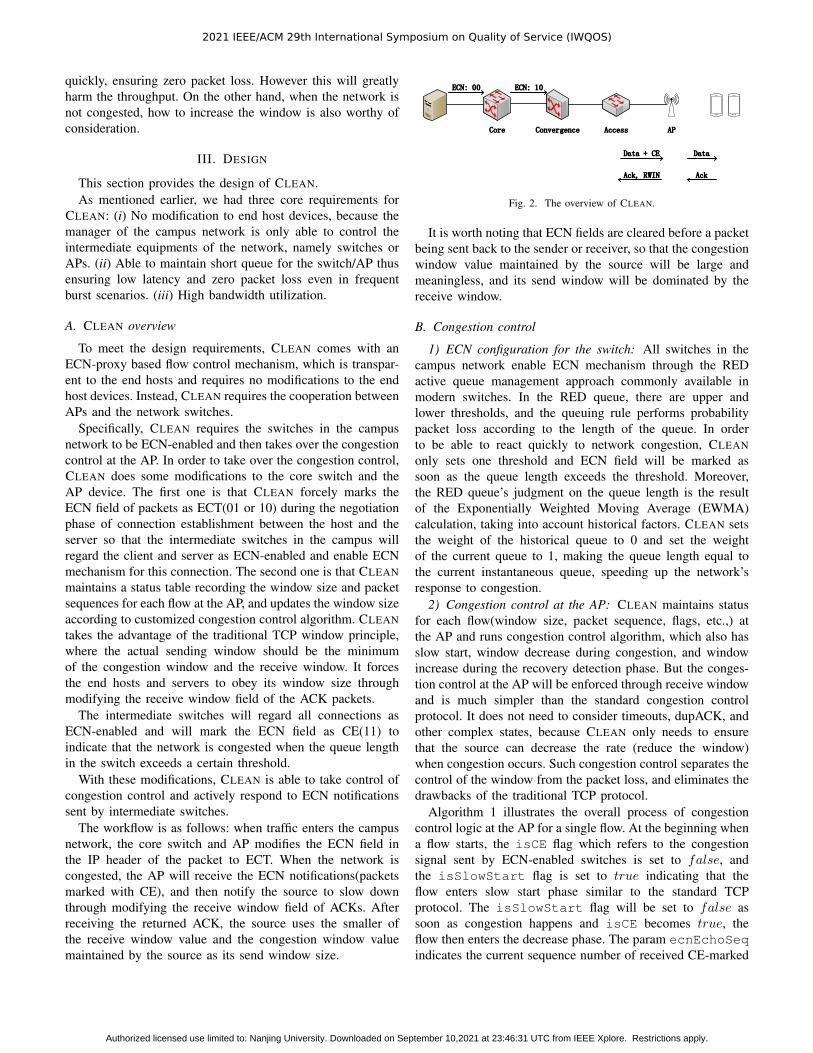
The workflow is as follows: when traffic enters the campusnetwork, the core switch and AP modifies the ECN field inthe IP header of the packet to ECT. When the network iscongested, the AP will receive the ECN notifications(packetsmarked with CE), and then notify the source to slow downthrough modifying the receive window field of ACKs. Afterreceiving the returned ACK, the source uses the smaller ofthe receive window value and the congestion window valuemaintained by the source as its send window size.
ECN: 00 ECN: 10
Data + CE
Ack, RWIN
Data
Ack
Core Convergence Access AP
Fig. 2. The overview of CLEAN.
It is worth noting that ECN fields are cleared before a packetbeing sent back to the sender or receiver, so that the congestionwindow value maintained by the source will be large andmeaningless, and its send window will be dominated by thereceive window.
B. Congestion control
1) ECN configuration for the switch: All switches in thecampus network enable ECN mechanism through the REDactive queue management approach commonly available inmodern switches. In the RED queue, there are upper andlower thresholds, and the queuing rule performs probabilitypacket loss according to the length of the queue. In orderto be able to react quickly to network congestion, CLEANonly sets one threshold and ECN field will be marked assoon as the queue length exceeds the threshold. Moreover,the RED queue’s judgment on the queue length is the resultof the Exponentially Weighted Moving Average (EWMA)calculation, taking into account historical factors. CLEAN setsthe weight of the historical queue to 0 and set the weightof the current queue to 1, making the queue length equal tothe current instantaneous queue, speeding up the network’sresponse to congestion.
2) Congestion control at the AP: CLEAN maintains statusfor each flow(window size, packet sequence, flags, etc.,) atthe AP and runs congestion control algorithm, which also hasslow start, window decrease during congestion, and windowincrease during the recovery detection phase. But the conges-tion control at the AP will be enforced through receive windowand is much simpler than the standard congestion controlprotocol. It does not need to consider timeouts, dupACK, andother complex states, because CLEAN only needs to ensurethat the source can decrease the rate (reduce the window)when congestion occurs. Such congestion control separates thecontrol of the window from the packet loss, and eliminates thedrawbacks of the traditional TCP protocol.
Algorithm 1 illustrates the overall process of congestioncontrol logic at the AP for a single flow. At the beginning whena flow starts, the isCE flag which refers to the congestionsignal sent by ECN-enabled switches is set to false, andthe isSlowStart flag is set to true indicating that theflow enters slow start phase similar to the standard TCPprotocol. The isSlowStart flag will be set to false assoon as congestion happens and isCE becomes true, theflow then enters the decrease phase. The param ecnEchoSeqindicates the current sequence number of received CE-marked
2021 IEEE/ACM 29th International Symposium on Quality of Service (IWQOS)
Authorized licensed use limited to: Nanjing University. Downloaded on September 10,2021 at 23:46:31 UTC from IEEE Xplore. Restrictions apply.

Algorithm 1 Congestion control at the AP1: if isCE == true then2: epochStartT ime← Now;3: if ecnEchoSeq>ecnCWRSeq then4: Wmax ← windowSize;5: ecnCWRSeq ← ecnEchoSeq + (windowSize −
1) ∗MSS;6: windowSize← windowSize/2;7: Wmin ← windowSize;8: isSlowStart← false;9: end if
10: else if isSlowStart == true then11: windowSize+ = 1;12: else13: K ← ((Wmax −Wmin)/C)
1/3;14: t← Now − epochStartT ime;15: windowSize← C ∗ (t−K)3 +Wmax;16: end if
packet and ecnCWRSeq refers to the next minimum sequencenumber that window decrease should happen, ensuring thatwindow size be decreased at most once in a window time,similar to the mechanism in DCTCP [3]. If a packet is notCE-marked, and the flow is not in slow start phase, the flowthen enters the fast recovery and active detection phase.
When the network is not congested, it implies that thenetwork may have the remaining bandwidth. There are twostages here, one is fast recovery, that is, the window is restoredto the size of the original congestion point, and the other is theactive detection stage. For the behavior of how to increase thewindow, CUBIC is a more mature solution. Therefore, in thewindow increase part, we use the CUBIC curve to calculatethe target value that the receive window should reach. TheCUBIC curve’s expression is as follows:
W = C × (t−K)3+Wmax, (1)
where Wmax is the window size of the last congestion, C is aCUBIC parameter, t is the elapsed time from the last windowreduction, and K is the time required to increase W to Wmax.
When the network does not encounter congestion, it firstquickly restores to the window size of the last congestion,and then maintains it for a long time nearby. When there isno congestion for a long time, it implies that the network hasa large amount of remaining bandwidth unused, so it quicklydetects the upper limit of the bandwidth that can be used.
C. Optimization of window decrease algorithm
From the description of the congestion control algorithm, wecan see that the AP roughly reduces the receive window to halfof the original when congested, which may cause throughputloss. Therefore, we optimize the window decrease part of thealgorithm. Inspired by DCTCP, we calculate the correspondingmultiplicative decrease factor α according to the degree of
network congestion, use this factor to reduce the window,instead of fixedly reducing it to half, as shown in (2).
W =W × (1− α/2) . (2)
DCTCP counts the proportion of CE-marked packets atthe receiver. In order not to destroy the Delayed ACK [5]mechanism, DCTCP needs to use a two state state-machineat the receiver. Different from DCTCP, CLEAN directly esti-mates the degree of network congestion at the AP. The APobserves whether the incoming data packet has CE markingand performs statistics. It has no effect on the Delayed ACKmechanism. The congestion level F is updated once in awindow, and the multiplicative subtraction factor is calculatedusing the EWMA method, as shown in (3). According to theDCTCP recommendation, g is set to 1/16 in CLEAN.
α = (1− g)× α+ g × F. (3)
We replaced Line 6 of Algorithm 1 with (2). This changeis small but very effective. This optimization allows the linkbandwidth to be fully utilized. In our simulation tests, althoughthe algorithm can guarantee zero packet loss before and afteroptimization, the throughput of a single flow is only 820Mbpsbefore optimization (the bottleneck is 850Mbps), and afteroptimization the bandwidth can be fully utilized.
IV. EVALUATION
A. Setup
We build a campus network topology according to Fig. 1in NS3. A large server is set to simulate the cloud outsidethe campus and sends traffic into the campus network. Thelink bandwidth between the server and the campus networkcore switch is 100Gbps. The link bandwidth between thecore switch and the aggregation switch is 40Gbps, and thelink bandwidth between the aggregation switch and the accessswitch is 10Gbps. There is an AP connected to the accessswitch with an 1Gbps link. We configure the wireless protocolstandard as 802.11ax 5G and configure 2x2 MIMO, which canmake the maximum rate of the AP reach 850Mbps. Both thecore switch and the aggregation switch have a shared bufferof 12MB. The buffer size of the access switch is set to 4MB,while the AP has a larger buffer of 12MB. The topology issetup according to our real-world campus network experienceand is supposed to simulate the real campus network architec-ture to the greatest extent.
As CUBIC is widely deployed on Windows and Linuxmachines, we configure the TCP congestion control protocol asTCP-CUBIC in NS3 in order to show the packet loss situationencountered by the campus network under the traditional WANTCP protocol. We also repeat the experiments with TCP-NewReno for comparison.
The base RTT is set to 10ms, which is the mainstreamscenario for WAN traffic in campus networks. The ECNfunction of the switch is enabled and the threshold is set 150packets according to the DCTCP recommendation [3].
2021 IEEE/ACM 29th International Symposium on Quality of Service (IWQOS)
Authorized licensed use limited to: Nanjing University. Downloaded on September 10,2021 at 23:46:31 UTC from IEEE Xplore. Restrictions apply.

0 1 2 3 4 5Time (s)
0
500
1000
1500
Queu
e le
ngth
(pac
kets
)
NewRenoCUBICClean
Fig. 3. The queue length of the access switch at the non-bottleneck.
B. Performance
1) Queue length and throughput: We first start a TCP flow,and then add 20 burst flows to test the buffer pressure of theswitch in the burst scenario. As shown in the Fig. 3, whenCLEAN is not applied, due to the greedy feature of TCP, theflow quickly occupies the buffer of the switch, and a queue isestablished in the switch, which is prone to packet loss. Afterapplying CLEAN, we can see that the length of the queue isalways maintained near the ECN threshold we set. This notonly can significantly reduce the RTT of the traffic, but alsoleaves a lot of buffer space to deal with bursts.
It is worth noting that even if the congestion control protocolis both based on packet loss, the queue length curve of CUBICis different from that of NewReno. When the TCP flow starts,NewReno will lose packets due to slow start, but CUBICwill not. This is because Hystart [6] is enabled in the newerCUBIC version, and slow start is exited when continuous ackis received quickly. Nevertheless, CUBIC still cannot copewith packet loss in burst scenarios. It can be observed fromthe figure that after burst traffic enters, the switch buffer isquickly filled up and packet loss occurs.
As shown in the Fig. 4, in CLEAN, since both the switchand the AP maintain a short queue length, the queuing timeis very small, and the RTT is close to the propagation timeplus the transmission time. As NewReno or CUBIC are bothcongestion control protocols based on packet loss and packetswill occupy all available buffers. This causes their queuingtime to be several times or even ten times that of the baseRTT, which harms their real RTT.
According to [7], the algorithm based on packet loss hassuch a conclusion: if the number of buffers exceeds the BDP ofthe connection, then the periodic packet loss caused by bufferoverflows does not result in a reduction in TCP throughput.Therefore, as shown in the Fig. 5, the sender throughput ofNewReno and CUBIC is slightly larger than the bottleneckbandwidth, but due to packet loss, their Goodput will besmaller than the bottleneck bandwidth. In contrast, CLEANis basically consistent with the bottleneck bandwidth in termsof both the sender throughput and goodput, indicating a highbandwidth utilization.
In addition to the 20 burst flows scenario, we also testedthe queue length of the switch in the 10, 40, and 80 burstflows scenario. As shown in the Fig. 6, after applying CLEAN,the switch can maintain the queue length near the thresholdin any scenario. Fig. 6 (b) also shows the maximum queuelength generated at the burst point in the switch. The results
mean 95th-pct 99th-pct0
20
40
60
80
100
120
RTT
(ms)
NewRenoCUBICClean
Fig. 4. RTT.
SendThput Goodput800810820830840850860870
Thro
ughp
ut (M
bps)
NewRenoCUBICClean
Fig. 5. The throughput of the senderand Goodput.
0 100 200 300 400Queue length (packets)
0.0
0.2
0.4
0.6
0.8
1.0
CDF
burst of 10 flowsburst of 20 flowsburst of 40 flowsburst of 80 flows
(a) CDF of queue length
10 20 40 80The number of burst flows
0
200
400
600
800
Max
que
ue le
ngth
(pac
kets
)
(b) max queue length
Fig. 6. The queue length in the 10, 20, 40, and 80 burst flows scenario.
demonstrates that with CLEAN, the established queue can beemptied quickly.
2) Convergence: To test whether CLEAN can quickly con-verge to a fair share, we start a single flow at the beginning,and then add a flow every 5s. The results are shown in theFig. 7. It can be observed from the figure that each joined flowcan converge to their fair share in a short period of time, whichshows that CLEAN performs well in terms of convergence.
V. RELATED WORK
The congestion control protocol of the WAN is developingvery rapidly, from the earlier Reno [8] to NewReno [1], High-speed TCP [9], BIC [10] and CUBIC [2]. These protocolswork hard to improve TCP performance on paths with highBDP. However, as congestion control protocols based onpacket loss, they do not care about the length of the queue,so that they bring high throughput while also bringing highdelay. BBR [11] does not take the occurrence of packet lossor delay increase as a signal of congestion. Alternatively, itperiodically detects the capacity of the network. As a result, ithas a better control over the queue length. However, we cannotrequire all senders and receivers in the campus network to useBBR. In addition, if the switch buffer is large, the bandwidthoccupied by BBR will be smaller when competing with moreaggressive protocols(e.g. CUBIC).
0 5 10 15 20 25 30 35 40Time (s)
0
250
500
750
Thro
ughp
ut (M
bps) flow 1
flow 2flow 3flow 4
flow 5flow 6flow 7
Fig. 7. Time series of throughput.
2021 IEEE/ACM 29th International Symposium on Quality of Service (IWQOS)
Authorized licensed use limited to: Nanjing University. Downloaded on September 10,2021 at 23:46:31 UTC from IEEE Xplore. Restrictions apply.

In order to control the queue length better, some schemesbased on explicit feedback are proposed, such as ECN [12],VCP [13], RCP [14], etc. Schemes like VCP and RCP requireswitches to perform computation which is not widely availablein most commodity switches. Therefore, ECN is widely used,especially in the data center networks, such as DCTCP [3],D2TCP [15], DCQCN [4] and some other strategies [16]–[18].They show that ECN can effectively control the queue lengthto achieve low latency and high throughput simultaneously.HPCC [19] uses the INT feature to implement high precisioncongestion control. For these protocols, whether using ECN orINT, they all need the joint support of network intermediateequipments and end hosts, which is always a major challengefor campus networks.
To solve this problem, we used the receive window tocontrol the end hosts. The earlier literature related to thisarea has [20]–[22]. They modify the receive window in TCPacknowledgments returning to the source. These methods arerelatively crude and cannot maintain the switch queue ata stable length. If the topology has multiple bottlenecks,each switch needs to perform similar calculations, which isexpensive. They have also been found to be vulnerable topacket loss and poor compatibility with some TCP sendingoperating systems. The recent literature related to the useof the receive window is VCC [23], [24], which decreasesthe receive window to force the guest to have fewer sendpackets in the hypervisor. However, VCC is used in multi-tenant data centers, and it is not suitable for campus networkenvironments. And more importantly, it does not mention howto calculate the appropriate window size.
VI. CONCLUSION
In this paper, we propose CLEAN, a queue length controlscheme via transparent ECN-proxy for campus networks.CLEAN takes over the congestion control for end host devicestransparently through modifying the ECN and receive windowfield at the last hop of the campus network. Evaluation resultsshow that CLEAN can achieve zero packet loss without lossof throughput, which greatly reduces latency. For the 99thpercentile, CLEAN reduces the latency by 85%.
ACKNOWLEDGMENT
The authors would like to thank anonymous reviewers fortheir valuable comments. This research is supported by theKey-Area Research and Development Program of Guang-dong Province 2020B0101390001, the National Natural Sci-ence Foundation of China under Grant Numbers 61772265,61802172, and 62072228, the Fundamental Research Fundsfor the Central Universities, the Collaborative Innovation Cen-ter of Novel Software Technology and Industrialization, andthe Jiangsu Innovation and Entrepreneurship (Shuangchuang)Program. Jiaqing Dong and Chen Tian are co-correspondingauthors.
REFERENCES
[1] S. Floyd, “RFC 6582,” https://tools.ietf.org/html/rfc6582.
[2] S. Ha, I. Rhee, and L. Xu, “CUBIC: A new TCP-friendly high-speedTCP variant,” ACM SIGOPS operating systems review, vol. 42, no. 5,pp. 64–74, 2008.
[3] M. Alizadeh, A. Greenberg, D. A. Maltz, J. Padhye, P. Patel, B. Prab-hakar, S. Sengupta, and M. Sridharan, “Data center TCP (DCTCP),” inProceedings of the ACM SIGCOMM 2010 conference, 2010, pp. 63–74.
[4] Y. Zhu, H. Eran, D. Firestone, C. Guo, M. Lipshteyn, Y. Liron, J. Padhye,S. Raindel, M. H. Yahia, and M. Zhang, “Congestion control for large-scale RDMA deployments,” ACM SIGCOMM Computer CommunicationReview, vol. 45, no. 4, pp. 523–536, 2015.
[5] R. Braden, “RFC 1122,” https://tools.ietf.org/html/rfc1122.[6] S. Ha and I. Rhee, “Taming the elephants: New TCP slow start,”
Computer Networks, vol. 55, no. 9, pp. 2092–2110, 2011.[7] S. Varma, Internet congestion control. Morgan Kaufmann, 2015.[8] V. Jacobson, “Congestion avoidance and control,” ACM SIGCOMM
computer communication review, vol. 18, no. 4, pp. 314–329, 1988.[9] S. Floyd, “RFC 3649: HighSpeed TCP for large congestion windows,”
https://tools.ietf.org/html/rfc3649.[10] L. Xu, K. Harfoush, and I. Rhee, “Binary increase congestion control
(BIC) for fast long-distance networks,” in IEEE INFOCOM 2004, vol. 4.IEEE, 2004, pp. 2514–2524.
[11] N. Cardwell, Y. Cheng, C. S. Gunn, S. H. Yeganeh, and V. Jacobson,“BBR: Congestion-based congestion control,” Queue, vol. 14, no. 5, pp.20–53, 2016.
[12] K. Ramakrishnan, S. Floyd, and D. Black, “RFC 3168: The addition ofexplicit congestion notification (ECN) to IP,” https://tools.ietf.org/html/rfc3168.
[13] Y. Xia, L. Subramanian, I. Stoica, and S. Kalyanaraman, “One morebit is enough,” in Proceedings of the 2005 conference on Applications,technologies, architectures, and protocols for computer communications,2005, pp. 37–48.
[14] N. Dukkipati, Rate Control Protocol (RCP): Congestion control to makeflows complete quickly. Citeseer, 2008.
[15] B. Vamanan, J. Hasan, and T. Vijaykumar, “Deadline-aware datacenterTCP (D2TCP),” ACM SIGCOMM Computer Communication Review,vol. 42, no. 4, pp. 115–126, 2012.
[16] A. Munir, I. A. Qazi, Z. A. Uzmi, A. Mushtaq, S. N. Ismail, M. S. Iqbal,and B. Khan, “Minimizing flow completion times in data centers,” in2013 Proceedings IEEE INFOCOM. IEEE, 2013, pp. 2157–2165.
[17] D. Shan, W. Jiang, and F. Ren, “Absorbing micro-burst traffic byenhancing dynamic threshold policy of data center switches,” in 2015IEEE Conference on Computer Communications (INFOCOM). IEEE,2015, pp. 118–126.
[18] D. Shan and F. Ren, “Improving ECN marking scheme with micro-burst traffic in data center networks,” in IEEE INFOCOM 2017-IEEEConference on Computer Communications. IEEE, 2017, pp. 1–9.
[19] Y. Li, R. Miao, H. H. Liu, Y. Zhuang, F. Feng, L. Tang, Z. Cao,M. Zhang, F. Kelly, M. Alizadeh et al., “HPCC: High precisioncongestion control,” in Proceedings of the ACM Special Interest Groupon Data Communication, 2019, pp. 44–58.
[20] L. Kalampoukas, A. Varma, and K. Ramakrishnan, “Explicit windowadaptation: A method to enhance TCP performance,” in Proceedings.IEEE INFOCOM’98, the Conference on Computer Communications.Seventeenth Annual Joint Conference of the IEEE Computer and Com-munications Societies. Gateway to the 21st Century (Cat. No. 98, vol. 1.IEEE, 1998, pp. 242–251.
[21] S. Karandikar, S. Kalyanaraman, P. Bagal, and B. Packer, “TCP ratecontrol,” ACM SIGCOMM Computer Communication Review, vol. 30,no. 1, pp. 45–58, 2000.
[22] H.-Y. Wei, S.-C. Tsao, and Y.-D. Lin, “Assessing and improving TCPrate shaping over edge gateways,” IEEE Transactions on Computers,vol. 53, no. 3, pp. 259–275, 2004.
[23] K. He, E. Rozner, K. Agarwal, Y. J. Gu, W. Felter, J. Carter, andA. Akella, “ACDC TCP: Virtual congestion control enforcement fordatacenter networks,” in Proceedings of the 2016 ACM SIGCOMMConference, 2016, pp. 244–257.
[24] B. Cronkite-Ratcliff, A. Bergman, S. Vargaftik, M. Ravi, N. McKeown,I. Abraham, and I. Keslassy, “Virtualized congestion control,” in Pro-ceedings of the 2016 ACM SIGCOMM Conference, 2016, pp. 230–243.
2021 IEEE/ACM 29th International Symposium on Quality of Service (IWQOS)
Authorized licensed use limited to: Nanjing University. Downloaded on September 10,2021 at 23:46:31 UTC from IEEE Xplore. Restrictions apply.