clean development mechanism project design … efficiency project at asahi india...clean development...
TRANSCRIPT
PROJECT DESIGN DOCUMENT FORM (CDM-SSC-PDD) - Version 03
CDM – Executive Board
1
CLEAN DEVELOPMENT MECHANISM
PROJECT DESIGN DOCUMENT FORM (CDM-SSC-PDD)
Version 03 - in effect as of: 22 December 2006
CONTENTS
A. General description of the small scale project activity
B. Application of a baseline and monitoring methodology
C. Duration of the project activity / crediting period
D. Environmental impacts
E. Stakeholders’ comments
Annexes
Annex 1: Contact information on participants in the proposed small scale project activity
Annex 2: Information regarding public funding
Annex 3: Baseline information
Annex 4: Monitoring Information

PROJECT DESIGN DOCUMENT FORM (CDM-SSC-PDD) - Version 03
CDM – Executive Board
2
Revision history of this document
Version
Number
Date Description and reason of revision
01 21 January 2003 Initial adoption
02 8 July 2005 • The Board agreed to revise the CDM SSC PDD to reflect
guidance and clarifications provided by the Board since
version 01 of this document.
• As a consequence, the guidelines for completing CDM SSC
PDD have been revised accordingly to version 2. The latest
version can be found at
<http://cdm.unfccc.int/Reference/Documents>.
03 22 December
2006 • The Board agreed to revise the CDM project design
document for small-scale activities (CDM-SSC-PDD), taking
into account CDM-PDD and CDM-NM.

PROJECT DESIGN DOCUMENT FORM (CDM-SSC-PDD) - Version 03
CDM – Executive Board
3
SECTION A. General description of small-scale project activity
A.1 Title of the small-scale project activity:
Energy efficiency project at Asahi India Glass Ltd., Bawal, Rewari.
Date : 25/03/2008
Version : 1
A.2 Description of the small-scale project activity:
The project activity is the installation of waste heat recovery system behind existing
furnace oil (FO) fired engines in the Bawal Glass manufacturing unit of Asahi India Glass
Ltd. (hereafter project participant or AIS). The project activity primarily aims at reducing
green house gas (GHG) emissions through increase in efficiency. The project activity
covers replacement of the conventional heating system (electric heaters & FO fired
thermic fluid heaters) and replacement of the conventional mechanical compression
cooling system by Vapour Absorption Chilling system.
The project activity is helping in sustainable development by GHG emission reduction.
Project activity is using more efficient system and replacing the conventional system and
thus reducing the emissions in the atmosphere. The erection and commissioning of project
will lead to direct/ indirect employment to contactors/ sub-contactors and contract labours.
View of project participants on the contribution of the project activity to sustainable
development:
AIS which is the owner of the project activity, believes that the project activity will
contribute and has further potential to shape the economic, environmental and social life
of the people in the region.
Contribution of Project Activity to Sustainable Development:
Indian economy is highly dependent on fossil fuel to generate energy and for production
processes. Conventional power plants are the major consumers of fossil fuels in India and
yet the basic electricity needs of a large section of population are not being met.
This results in excessive demands for electricity and places immense stress on the
environment. Changing fossil fuel consumption patterns will require a multi-pronged
strategy focusing on demand, reducing wastage of energy and the optimum use of
Renewable Energy (RE) sources.
Government of India has stipulated following indicators for sustainable development in
the interim approval guidelines1for CDM projects.
1. Social well-being
2. Economic well-being
3. Environmental well-being
1 Ministry of Environment and Forest, web site: http://envfor.nic.in:80/divisions/ccd/cdm_iac.html

PROJECT DESIGN DOCUMENT FORM (CDM-SSC-PDD) - Version 03
CDM – Executive Board
4
4. Technological well-being
1. Social well being:
� The plant site is in sub-urban area where poverty and other economic backwardness are
prevailing. The project would lead to the development of the region.
� During project implementation, employment for local people around the plant site will be
generated.
� Other than these, there are various kinds of mechanical work, which will generate
employment opportunity on regular and permanent basis.
2. Economic well being:
� The project activity generates employment in the local area.
� Energy savings, in terms of energy units and costs, benefits the industry
� The project creates a business opportunity for local stakeholders such as bankers,
consultants, suppliers, manufacturers, contractors etc.
3. Environmental well being:
� Energy efficiency project reduces energy consumption, generated by using fossil fuels.
Project also reduces pollution in general. All the necessary measures have been taken in
the plant’s design for minimizing the impact on the ecology of the environment.
4. Technological well being:
� The technology selected for the project is a more energy efficient and innovative.
� This ensures an optimum usage of fuel thereby leading to resource sustainability.
In view of the above, the project participant considers that the project activity profoundly
contributes to the sustainable development in the region of the project activity.
A.3 Project participants:
Name of Party involved (*)
((host) indicates a host
Party)
Private and/or public entity(ies)
project participants (*) (as
applicable)
Kindly indicate if the Party
involved wishes to be
considered as project
participant (Yes/No)
India. • Private entity - M/s Asahi
India Glass Ltd. (AIS)
No.
(*) In accordance with the CDM modalities and procedures, at the time of making the CDM-PDD
public at the stage of validation, a Party involved may or may not have provided its approval. At
the time of requesting registration, the approval by the Party (ies) involved is required.
A.4 Technical description of the small-scale project activity:
A.4.1 Location of the small-scale project activity:

PROJECT DESIGN DOCUMENT FORM (CDM-SSC-PDD) - Version 03
CDM – Executive Board
5
A.4.1.1 Host Party(ies):
India
A.4.1.2 Region/State/Province etc.:
Haryana
A.4.1.3 City/Town/Community etc:
Tehsil – Bawal, Dist. – Rewari
A.4.1.4 Details of physical location, including information allowing
the unique identification of this small-scale project activity :
The project activity will be installed in the existing facility of AIS. The project activity will be
located at Bawal 15 km from the Rewari city in Haryana, India. Bawal is located between latitude
of 28.080N and longitude of 76.580E at altitude of 872 Ft.

PROJECT DESIGN DOCUMENT FORM (CDM-SSC-PDD) - Version 03
CDM – Executive Board
6
Figure 01: Site Location

PROJECT DESIGN DOCUMENT FORM (CDM-SSC-PDD) - Version 03
CDM – Executive Board
7
A.4.2 Type and category(ies) and technology/measure of the small-scale project activity:
As defined under Appendix B of the simplified modalities and procedures for small-scale
CDM project activities, the project activity proposes to apply following project types and
categories:
� Type :III –Other Projects Activities
� Project Category :Energy efficiency and fuel switch measures for industrial
facility (III.Q) Version 01
Captioned project basically includes recovery of heat from flue gases of FO fired
generator sets for process heating and chilling. They are as follows-:
� Replacement of the conventional heating system i.e. electric heaters & FO fired
thermic fluid heaters for process heating.
� Replacement of the conventional mechanical compression cooling system by Vapour
Absorption Chilling system.
The system incorporates a heat recovery unit (HRU) that will be placed in exhaust gas
path of the FO fired engines to heat up thermic fluid. Exhaust gases will be flowing to the
HRU through a 3 way motorized damper. Depending on plant load, it will allow the gases
to go through HRU or bypass to atmosphere through existing chimney. Exhaust gases will
be cooled from 290 °C to 187 °C at rated load and can generate heat of 14.7 lac kCal/hr
from 2 X 3.6 MW engines. This heat will be picked by thermic fluid which will enter at
175 °C and leave the HRU at 237 °C.
HRU will be located just outside the engine room and thermic fluid will be pumped to the
existing thermic fluid heater area, where AIS has been able to replace existing thermopac
(2.75 lac kcal TP04), two electric heaters (100 kW and 80 kW respectively) in
dehumidifiers with thermic fluid radiators and electric heaters of 600 kW connected load
(avg. load is 220 kW) by thermic fluid radiators for hot air. Returning thermic fluid will
be passing through a heat exchanger which will heat up water from 152 °C to 162 °C.
Hot water thus generated will be utilized in Vapour Absorption Machine (VAM) machine.
Absorption machine will generate chilled water at 7 °C from 12 °C returning water.
Existing Direct Expansion (DX) system will be converted to Chilled Water (CHW)
system by adding Air handling unit (AHUs) and Fan Coil Unit (FCU’S).The system
incorporate cooling tower and pump-sets with necessary piping and valves. Absorption
machine needs cooling water at 32 °C.
To take care of the volumetric expansion of the thermic fluid due to temperature increase
and releasing air (gas) from the thermic fluid pipe line, an expansion tank will be
provided. The expansion tank will be at above the highest point elevation in the thermic
fluid system.
AIS have designed the system in such a way to utilize the system with extra flexibility, as
during peak requirement of heating, cooling load will be lesser and during peak
requirement of cooling, heating load will be lesser and AIS can utilize the extra heating
and cooling during peak requirements accordingly to get maximum out put out of the
system.

PROJECT DESIGN DOCUMENT FORM (CDM-SSC-PDD) - Version 03
CDM – Executive Board
8
A.4.3 Estimated amount of emission reductions over the chosen crediting period:
Years
Annual estimation of emission reductions in tonnes
of CO2
2008 – 09 3654
2009 – 10 3654
2010 – 11 3654
2011 – 12 3654
2012 – 13 3654
2013 – 14 3654
2014 – 15 3654
2015 – 16 3654
2016 – 17 3654
2017 – 18 3654
Total estimated reductions
(tonnes of CO2 e)
36540
Total number of crediting years 10
Annual average of the estimated
reductions over the crediting period
(tCO2 e)
3654
A.4.4 Public funding of the small-scale project activity:
No ODA was received for the proposed project activity.
A.4.5 Confirmation that the small-scale project activity is not a de-bundled component of
a large scale project activity:
Appendix C, paragraph 2 of the Simplified Modalities and Procedures for Small-Scale
CDM project activities states:
� A proposed small-scale project activity shall be deemed to be a de-bundled component of
a large project activity if there is a registered small-scale CDM project activity or an
application to register another small-scale CDM project activity:
� With the same project participants;
� In the same project category and technology/measure; and
� Registered within the previous 2 years; and
� Whose project boundary is within 1 km of the project boundary of the proposed small-
scale activity at the closest point.
� If a proposed small-scale project activity is deemed to be a de-bundled component in
accordance with paragraph 2 above, but total size of such an activity combined with the
previous registered small-scale CDM project activity does not exceed the limits for small-
scale CDM project activities as set in paragraph 6 (c) of the decision 17/CP.7, the project
activity can qualify to use simplified modalities and procedures for small-scale CDM
project activities.

PROJECT DESIGN DOCUMENT FORM (CDM-SSC-PDD) - Version 03
CDM – Executive Board
9
On the basis of the above, the project activity cannot be considered as de-bundled
component of a large project activity as it is first small-scale project activity for AIS,
Bawal.
SECTION B. Application of a baseline and monitoring methodology
B.1 Title and reference of the approved baseline and monitoring methodology applied to
the small-scale project activity:
Title: Other Project Activities - III.Q. Waste gas based energy systems (Version 01)
Reference: Appendix B of the simplified M & P for small-scale CDM project activities -
indicative simplified baseline and monitoring methodology for selected small scale CDM
project activity categories (Version – 07:28 November 2005).
B.2 Justification of the choice of the project category:
As defined under Appendix B of the simplified modalities and procedures for small-scale
CDM project activities, the project activity proposes to apply following project types and
categories:
� Type :III –Other Projects Activities
� Project Category :Energy efficiency and fuel switch measures for industrial
facility (III.Q) Version 01
Requirements with respect to technology/measure under III.Q. Waste gas based
energy systems (Version 01) are as follows.
1. The category is for project activities that utilize waste gas and/or waste heat at existing
facilities as an energy source for:
• Cogeneration; or
• Generation of electricity; or
• Direct use as process heat; or
• For generation of heat in elemental process (e.g. steam, hot water, hot oil, hot air).
2. The category is also applicable to project activities that use waste pressure to generate
electricity at existing facilities.
3. The recovery of waste gas/heat may be a new initiative or an incremental gain in an
existing practice.
4. In case the project activity is an incremental gain, the difference between the technology
used before project activity implementation and the project technology should be clearly
shown. It should be demonstrated why there are barriers for the project activity that did
not prevent the implementation of the technology used before the project activity
implementation.
5. Measures are limited to those that result in emission reductions of less than or equal to 60
kt CO2 equivalent annually. Wherever the measures lead to waste heat recovery which is
incremental to an existing practice of waste heat recovery, only the incremental gains in
PROJECT DESIGN DOCUMENT FORM (CDM-SSC-PDD) - Version 03
CDM – Executive Board
10
GHG mitigation should be taken into account and such incremental gains shall result in
emission reductions of less than or equal to 60 kt CO2 equivalent annually.
6. The category is applicable under the following conditions:
• The energy produced with the recovered waste gas/heat or waste pressure should be
measurable.
• Energy generated in the project activity shall be used within the facility where the
waste gas/heat or waste pressure is produced. An exception is made for the electricity
generated by the project activity which may be exported to the grid.
• The waste gas/heat or waste pressure utilized in the project activity would have been
flared or released into the atmosphere in the absence of the project activity. This shall
be proven by one of the following options:
o By direct measurements of energy content and amount of the waste gas/heat or
waste pressure for at least three years prior to the start of the project activity.
o Energy balance of relevant sections of the plant to prove that the waste gas/heat or
waste pressure was not a source of energy before the implementation of the
project activity. For the energy balance the representative process parameters are
required. The energy balance must demonstrate that the waste gas/heat or waste
pressure was not used and also provide conservative estimations of the energy
content and amount of waste gas/heat or waste pressure released.
o Energy bills (electricity, fossil fuel) to demonstrate that all the energy required for
the process (e.g. based on specific energy consumption specified by the
manufacturer) has been procured commercially. Project participants are required
to demonstrate through the financial documents (e.g. balance sheets, profit and
loss statement) that no energy was generated by waste gas/heat or waste pressure
and sold to other facilities and/or the grid. The bills and financial statements
should be audited by competent authorities.
o Process plant manufacturer’s original specification/information, schemes and
diagrams from the construction of the facility could be used as an estimate of
quantity and energy content of waste gas/heat produced for rated plant capacity
per unit of product produced.
7. For the purpose of this category waste gas/heat/pressure is defined as: by-product gas/heat
or pressure of machines and technical processes for which no useful application is found
in the absence of the project activity and for which it can be demonstrated that it has not
been used prior to, and would not be used in absence of the CDM project activity (e.g.
because of low pressure, heating value or quantity available). In the project scenario, this
waste gas/heat/pressure is recovered and conditioned for use.
The project activity fits under AMS III.Q - Waste gas based energy systems. The project
activity recovers heat from the waste gas and generates hot oil.
The indicative simplified baseline and monitoring methodology applicable to category III.Q
has been used for the project including baseline calculations. The emission reduction
calculation is based on amount of heat recovered from the waste gas by the project activity.
The annual emission reduction from the project activity is 3654 tCO2e, which is well below the
limit of 60 ktCO2e, as specified in the methodology.
The applicability criteria(s) of the applied methodology, AMS III.Q, with relevant project
justifications), are as follows:

PROJECT DESIGN DOCUMENT FORM (CDM-SSC-PDD) - Version 03
CDM – Executive Board
11
Para Methodology Requirement Applicability of Project Activity
1. The category is for project activities that
utilize waste gas and/or waste heat at
existing facilities as an energy source for:
• Cogeneration; or
• Generation of electricity; or
• Direct use as process heat source; or
• For generation of heat in element
process (e.g. steam, hot water, hot oil,
hot air).
The project activity entails recovery of the
heat content of the waste gas generated from
DG sets, utilization of the same in waste
heat recovery system to generate hot
thermic fluid. Therefore the project activity
meets the applicability condition of the
methodology.
2. The category is also applicable to project
activities that use waste pressure to generate
electricity at existing facilities.
The project activity does not involve usage
of the waste gas pressure for generation of
electricity. Therefore this applicability
condition is not applicable for the project
activity under consideration.
3. The recovery of waste gas/heat may be a
new initiative or an incremental gain in an
existing practice.
The project activity is a new initiative taken
by the project proponent and before the
project activity there has been no waste heat
recovery.
5. Measures are limited to those that result in
emission reductions of less than or equal to
60 kt CO2 equivalent annually.
The annual emission reduction from the
project activity is about 3654 ktCO2e which
is below the limit of 60 ktCO2e as specified
in the methodology.
6. The category is applicable under the
following conditions:
• The energy produced with the recovered
waste gas/heat or waste pressure should
be measurable
• Energy generated in the project activity
shall be used within the facility where
the waste gas/heat or waste pressure is
produced. An exception is made for the
electricity generated by the project
activity which may be exported to the
grid.
• The waste gas/heat or waste pressure
utilized in the project activity would
have been flared or released into the
atmosphere in the absence of the project
activity.
The energy recovered by the project activity
can be measured and monitored by the project
proponent.
The energy recovered by the project activity
will be utilized within the facility where the
waste gas is produced.
Before the project activity, the waste gas
produced by the DG sets was being released
in to the atmosphere
Therefore the project activity meets the
applicability condition of the methodology.

PROJECT DESIGN DOCUMENT FORM (CDM-SSC-PDD) - Version 03
CDM – Executive Board
12
7. For the purpose of this category waste
gas/heat/pressure is defined as: by-product
gas/heat or pressure of machines and
technical processes for which no useful
application is found in the absence of the
project activity and for which it can be
demonstrated that it has not been used prior
to, and would not be used in absence of the
CDM project activity (e.g. because of low
pressure, heating value or quantity
available). In the project scenario, this
waste gas/heat/pressure is recovered and
conditioned for use.
The waste gas utilized in the project activity is
the exhaust gas obtained from the DG sets
which were exhausted in to the atmosphere
before the project activity. The heat available
in the exhaust gas was not utilized before the
project activity because of technical barriers
explained in Section B.
Therefore the project activity meets the
applicability condition of the methodology.
B.3 Description of the project boundary:
The physical, geographical site of the facility where the heat is produced and transformed
into useful energy delineates the project boundary. Project boundary includes all energy
efficiency schemes listed in section A.4.2.
Figure 2, : Project Boundary
B.4 Description of baseline and its development:
Detail of the energy and emission baseline has been developed using the baseline methodology
prescribed by the UNFCCC in Appendix B to Simplified M&P for small scale COM projects
activities belonging to AMS III.Q.
GENERATO
Heat Recovery Unit
to generate 187 °C
hot oil
FO Engines
(2 nos x 3.6 MW)
By pass
valve
Exhaust
gases
Chimney
VAM
AHU &
FCU
Boiler &
Thermic
Fluid
Radiators
Chilled Water
Heating
load Hot Water Generator
7 °C
Water
Hot Oil
12 °C

PROJECT DESIGN DOCUMENT FORM (CDM-SSC-PDD) - Version 03
CDM – Executive Board
13
As per para 9 of AMS III.Q "For computing the emissions in the baseline the procedure
provided in paragraphs 6 to 13 of AMS I.C shall be used".
From paragraphs 6 to 13 of AMS I.C paragraph 10 is applicable for this project which is as
follows:
10. For steam/heat produced using fossil fuels the baseline emissions are calculated as
follows:
BEy = HGy * EF CO2 /ηth
Where:
BEy the baseline emissions from steam/heat displaced by the project activity during
the year y in tCO2e.
HGy the net quantity of steam/heat supplied by the project activity during the year y in
TJ.
EFCO2 the CO2 emission factor per unit of energy of the fuel that would have been used
in the baseline plant in (tCO2 / TJ), obtained from reliable local or national data if
available, otherwise, IPCC default emission factors are used.
ηth the efficiency of the plant using fossil fuel that would have been used in the
absence of the project activity.
Step I: Determination of Energy Baseline
In the absence of the project activity, the existing furnace oil fired units and electricity
consumption from the grid would have continued over the entire crediting period. Therefore, the
energy baseline would be the furnace oil consumption of thermic fluid heaters and electricity
consumption from the grid equivalent to power saving by the Waste Heat Recovery. Thus, the
energy sources primarily include furnace oil and electricity consumption. The base line data
(two years data of the years prior to project implementation) has been used to determine the
energy baseline.
Step II: Determination of carbon intensity of the chosen baseline
As stated above, there are three energy sources
• Electrical energy drawn from Northern Region Grid and produced in FO based CPP
• Thermal energy generated from furnace oil combustion for steam boilers and
The emission coefficient for each of these sources has been determined herein:

PROJECT DESIGN DOCUMENT FORM (CDM-SSC-PDD) - Version 03
CDM – Executive Board
14
(A) Emission Coefficient of the Northern Regional Grid
In the proposed baseline, Northern Region grid is used as the reference region for
estimating the current generation mix. Using the methodology available for small-scale
project activities, the weighted average emissions (t CO2 e/GWh) of current generation
mix of Northern Region grid of India is used for the calculation of baseline. The weighted
average emission factor data calculated and provided by Central Electricity Authority
(CEA)2 is used for the proposed project activity.
(B) Emission Coefficient for Furnace Oil (FO)
The emission coefficient is based on NCV and Emission Factor
As per the provisions of paragraph 59 of Appendix B of Simplified Modalities and Procedures
for Small Scale COM Project Activities [FCCC/CP/2002/7/Add.3, English, Page 21], the
emission coefficient (measured in kg of CO2 / kg of Furnace Oil) for the furnace oil reduced
had been calculated in accordance with the IPCC default values as well as the laboratory
analysis and stoichiometric analysis.
Emission Factors
The emission factors are based on IPCC Guidelines for National Greenhouse Gas Inventories and
are given below.
Fuel Emission Factor
(kg CO2/TJ)3
Emission factor
(kg CO2/kg)4
Calorific Value
(TJ/Gg)5
Residual Fuel Oil
(Furnace Oil)
77400 3.13 40.40
B.5 Description of how the anthropogenic emissions of GHG by sources are reduced
below those that would have occurred in the absence of the registered small-scale CDM
project activity:
The project reduces anthropogenic emission of greenhouse gases by source below those
that would have occurred in the absence of the CDM project activity.
As per decision 17/cp.7 Para 43, a CDM project is additional if anthropogenic emission of
greenhouse gases by source are below those that would have occurred in the absence of
the CDM project activity.
• Additionality
According to Attachment A to Appendix B of the simplified modalities and procedures for
CDM small-scale project activities, evidence to why the project is additional is offered
under the following categories of barriers:
2 http://cea.nic.in/planning/c%20and%20e/Government%20of%20India%20website.htm

PROJECT DESIGN DOCUMENT FORM (CDM-SSC-PDD) - Version 03
CDM – Executive Board
15
Project participants shall provide an explanation to show that the project activity would
not have occurred anyway due to at least one of the following barriers:
a) Investment barrier: a financially more viable alternative to the project activity would
have led to higher emissions;
b) Technological barrier: a less technologically advanced alternative to the project activity
involves lower risks due to the performance uncertainty or low market share of the new
technology adopted for the project activity and so would have led to higher emissions;
c) Barrier due to prevailing practice: prevailing practice or existing regulatory or policy
requirements would have led to implementation of a technology with higher emissions;
d) Other barriers: without the project activity, for another specific reason identified by the
project participant, such as institutional barriers or limited information, managerial
resources, organizational capacity, financial resources, or capacity to absorb new
technologies, emissions would have been higher.
Identify barriers that would prevent the implementation of type of the proposed project
activity. We have selected (b) (c) & (d) to provide an explanation.
The project suffered technical barriers, in obtaining management consent for execution, due to the
following circumstances:
The project is novel in the entire Indian industry and to the glass industry. Recovery of heat from
engine exhaust to generate steam or hot water is well proven. The process at AIS requires thermic
fluid at 237 °C temperature. The process does not require hot water or steam. Recovery of heat
from engine flue gases to heat the return thermic fluid and displace fossil fuel is totally novel or
first of its kind. Though the suppliers and engineers were confident of the success, the uniqueness
of the project provided a stumbling block. It was also not practical, to install or try a pilot plant.
In the absence of data of any proven similar waste heat recovery project, it was difficult to
establish the reliability and issues of concern.
Glass making is traditionally a continuous process industry. Hence, M/s. AIS prefers expensive
DG power to the utility supplies, as the same is lesser reliable. Any power tripping in the glass
sector has a serious impact on the value and quantum of production. Business as usual with DG
set (including standby) for reliable power with oil fired thermic fluid heaters for process heating
and mechanical compressors (with standby) for cooling are safe options and were being practiced.
The technical barriers being faced were primarily due to absence of data or experience from any
other similar waste heat energy recovery projects and include:
� Recovering heat from flue gas between 240 to 187 °C with thermic fluid heat at 237 °C outlet
and 175 °C inlet, without phase change, did raise certain issues like appropriate heat transfer
area
� Severe requirements of soot blowing due to high dust concentration in engine exhaust
� Providing effective hot flue bypass during low circulation of thermic fluid
� Additional equipment for O&M which are not part of the core business
� Requirement of installation of hot water generator in the return path of thermic fluid to obtain
appropriate temperature differential for heat transfer. This also results in additional
investment in hot water generator using thermic fluid & hot water fired vapour absorption
chillers

PROJECT DESIGN DOCUMENT FORM (CDM-SSC-PDD) - Version 03
CDM – Executive Board
16
� Requirement of retaining & maintaining the existing oil fired thermic fluid heaters and
mechanical refrigeration compressors, as standby units because of the lack of experience and
low credibility of the heat recovery system.
These technical barriers could have severe financial implications on the facility operations, as
compared to the savings potential from the waste heat recovery. This was due to the below
factors:
� All the engines including standbys are connected to a common chimney. The waste heat
recovery unit would be installed before this chimney. A bypass to the heat recovery unit is
provided. However, possibility of requirement of shutting down all the DG sets during any
outage of the waste heat recovery system could occur. This will lead to total closure of all
activities in the facility, loss of material on which work is in progress and loss of production.
AIS caters mainly to the automotive industry. Most of its buyers follow no inventory scheme,
wherein the requirement of prompt and timely supply is critical to retain market share.
� Standby oil fired thermic fluid heaters and mechanical compressors are to be maintained in
event of outage of the waste heat recovery system. However, bringing these standbys into
operation during any outage will also require considerable time. Each equipment would have
its own start-up procedure and all the necessary changeover valves will need to be operated.
Hence any outage in the system will lead to a stoppage in production due to absence of
required process heat & cooling. Apart from financial loss due to decrease in production, this
would also upset the entire production & manufacturing chain.
From the above submissions, it is evident that the energy conservation project by recovering
engine flue gas waste heat by heating of thermic fluid had significant technical barriers which
could have substantial impact on the facility operations & financials.
The management of AIS remains committed to ecological & environmental preservations. Energy
conservation has always been an important agenda for the organisation. The additional fiscal
benefits which could be received due to the energy savings and corresponding CERs will
motivated the management to take such projects. Apart from fiscal benefits, the management of
AIS were extremely keen to participate in the CDM under Kyoto Protocol, as their contribution
towards decrease in GHG emissions. The fiscal benefits and philosophy of the Kyoto Protocol
provided the opportunity based on which the threats to the above barriers could be taken.
B.6 Emission reductions:
B.6.1 Explanation of methodological choices:
The procedure followed for estimating the emissions reductions from this project activity
during the crediting period are as per the following steps:
Step 1: Calculation of baseline emission
BEy = BEFO,y + BEGrid,y
Where,
BEy is the baseline emission in year Y,
BEFO,y the baseline emission due to use of furnace oil in year Y,
BEGrid,y the baseline emission due to use of grid electricity in year Y,

PROJECT DESIGN DOCUMENT FORM (CDM-SSC-PDD) - Version 03
CDM – Executive Board
17
Step 2: Calculation of baseline emission due to FO
BEFO,y = HGy * EF FO, CO2
Where,
BEFO,y the baseline emissions from steam/heat generated by FO displaced by the
project activity during the year y in tCO2e.
HGy the net quantity of heat displaced by the project activity during the year y
in TJ.
EFCO2 the CO2 emission factor per unit of energy of the fuel that would have
been used in the baseline plant in (tCO2 / TJ), obtained from reliable local
or national data if available, otherwise, IPCC default emission factors are
used.
Step 3: Calculation of baseline emission due to electricity
BEGrid,y = QElec.y, * EFGrid,Y
Where,
BEGrid,y the baseline emission due to use of grid electricity in year Y,
QElec.y, quantity of electricity displaced in year Y,
EFGrid,Y emission coefficient of northern grid in year Y.
Step 4: Calculation of project emission
PEy = QElec. aux., y * EFGrid,Y
Where,
PEy the project emission due to use of grid electricity in year Y,
QElec. aux., y the amount of electricity consumed extra due to project activity,
EFGrid,Y emission coefficient of northern grid in year Y.
Step 5: Calculation of emission reduction
ERy = BEy – PEy
Where,
ERy the emission reduction due to project activity in year Y,
BEy the baseline emission in year Y,
PEy the project emission due to use of grid electricity in year Y.
B.6.2 Data and parameters that are available at validation:
(Copy this table for each data and parameter)
Data / Parameter: Electricity
Data unit: MWh
Description: Electricity saving due to project activity
Source of data used: Plant records
Value applied: 3783
Justification of the The used data is from plant records.

PROJECT DESIGN DOCUMENT FORM (CDM-SSC-PDD) - Version 03
CDM – Executive Board
18
choice of data or
description of
measurement methods
and procedures
actually applied :
Any comment: --
Data / Parameter: CO2 Emission Factor
Data unit: t CO2/MWh
Description: Carbon Emission Factor
Source of data used: Central Electricity Authority
Value applied: 0.81
Justification of the
choice of data or
description of
measurement methods
and procedures
actually applied :
The used data is from an official source.
Any comment: --
Data / Parameter: Volume
Data unit: Litre
Description: Saving in FO Consumption
Source of data used: Plant records
Value applied: --
Justification of the
choice of data or
description of
measurement methods
and procedures
actually applied :
The used data is from plant records.
Any comment: --
Data / Parameter: Electricity
Data unit: MWh
Description: Additional consumption of electricity due to project activity
Source of data used: Plant records
Value applied: --
Justification of the
choice of data or
description of
measurement methods
and procedures
actually applied :
The used data is from plant records.
Any comment: --

PROJECT DESIGN DOCUMENT FORM (CDM-SSC-PDD) - Version 03
CDM – Executive Board
19
B.6.3 Ex-ante calculation of emission reductions:
Year Estimation of
project activity
emission (tonnes
CO2e /yr.)
Baseline
emissions
(tonnes CO2e /yr.)
Estimation of
leakage
(tonnes CO2e / yr.)
Estimation of
emission
reduction (tonnes
CO2e /yr.)
2008 – 09 0 3654 0 3654
2009 – 10 0 3654 0 3654
2010 – 11 0 3654 0 3654
2011 – 12 0 3654 0 3654
2012 – 13 0 3654 0 3654
2013 – 14 0 3654 0 3654
2014 – 15 0 3654 0 3654
2015 – 16 0 3654 0 3654
2016 – 17 0 3654 0 3654
2017 – 18 0 3654 0 3654
Total 0 36540 0 36540
B.6.4 Summary of the ex-ante estimation of emission reductions:
The procedure followed for estimating the emissions reductions from this project activity
during the crediting period are as per the following steps:
Step 1: Calculation of baseline emission
BEy = BEFO,y + BEGrid,y
Step 2: Calculation of baseline emission due to FO
BEFO,y = HGy * EF FO, CO2
Step 3: Calculation of baseline emission due to electricity
BEGrid,y = QElec.y, * EFGrid,Y
Step 4: Calculation of project emission
PEy = QElec. aux., y * EFGrid,Y
Step 5: Calculation of emission reduction
ERy = BEy – PEy
B.7 Application of a monitoring methodology and description of the monitoring plan:
B.7.1 Data and parameters monitored:

PROJECT DESIGN DOCUMENT FORM (CDM-SSC-PDD) - Version 03
CDM – Executive Board
20
(Copy this table for each data and parameter)
Data / Parameter: Electricity
Data unit: MWh
Description: Electricity saved due to all activities
Source of data to be
used:
Calculated from the plant records
Value of data --
Description of
measurement methods
and procedures to be
applied:
The value for all savings will be calculated from plant records. The data
will be archived both in electronic and paper form for crediting period +
2 years.
QA/QC procedures to
be applied:
--
Any comment: --
Data / Parameter: Electricity Consumption
Data unit: MWh
Description: Additional electricity consumed due to project activity
Source of data to be
used:
Plant records
Value of data --
Description of
measurement methods
and procedures to be
applied:
Electric meter connected to different machines and instrument in the
project boundary will record the consumption data. The data will be
archived in both electronic and paper form for crediting period + 2
years.
QA/QC procedures to
be applied:
--
Any comment: --
Data / Parameter: Volume
Data unit: Litre
Description: Saving in FO Consumption
Source of data to be
used:
Plant records
Value of data --
Description of
measurement methods
and procedures to be
applied:
The data will be archived in both electronic and paper form for
crediting period + 2 years.
QA/QC procedures to
be applied:
--
Any comment: --
Data / Parameter: Volume
Data unit: M3
Description: Quantity of waste gas
Source of data to be
used:
Calculated from Plant records

PROJECT DESIGN DOCUMENT FORM (CDM-SSC-PDD) - Version 03
CDM – Executive Board
21
Value of data --
Description of
measurement methods
and procedures to be
applied:
The data will be archived in both electronic and paper form for
crediting period + 2 years.
QA/QC procedures to
be applied:
--
Any comment: --
B.7.2 Description of the monitoring plan:
As per the provisions of paragraph 14 of Draft simplified modalities and procedures for
small scale COM project activities [FCCC/CP/2002/7/Add.3, English, Page 21] the
"Project participants may use the simplified baseline and monitoring methodologies
specified in appendix B for their project category" if they meet the applicability criteria of
small scale COM project activity.
Since the project activity is a small-scale COM project of AMS III.Q. category, the
monitoring methodology and plan has been developed in line with the guidance provided
in paragraph 13 of category III.Q. for baseline emissions determination.
For baseline emissions determination, monitoring shall consist of:
(a) Metering the thermal and/or electrical energy produced. In case of thermal energy the
enthalpy of the thermal energy output stream like hot water/steam should be monitored.
(b) Metering the amount of waste gas or the amount of energy contained in the waste heat
or waste pressure.
As per para 14 "For project emissions determination, the Tool to calculate project or
leakage CO2 emissions from fuel combustion and the Tool to calculate project emissions
from electricity consumption shall be used".
Thus as per the methodology, monitoring shall consist of:
1. Metering of electricity and FO saving after the project activity.
2. Monitoring and metering of auxiliary power consumption of project activity.
3. Computation of Emission Factor from published CEA database.
Monitoring plan:
A Monitoring & Verification (M&V) Plan has been developed by the project proponent for
monitoring and verification of actual emission reductions. The Monitoring and
Verification (M&V) procedures define a project-specific standard against which the
project's performance (i.e. GHG reductions) and conformance with all relevant criteria will
be monitored and verified.
The aim is to enable this project have a clear, credible, and accurate set of monitoring,
evaluation and verification procedures. The purpose of these procedures would be to

PROJECT DESIGN DOCUMENT FORM (CDM-SSC-PDD) - Version 03
CDM – Executive Board
22
direct and support continuous monitoring of project performance/key project indicator to
determine project outcomes, greenhouse gas (GHG) emission reductions.
The project revenue (energy savings) is based on the quantum of heat recovered from the
waste gas as compared to the baseline fossil fuel consumption before project activity
implementation. The monitoring and verification system would mainly comprise of the
electronic power (energy) meters, furnace oil flow meters, steam flow meters, installed at
the each project activity site in order to measure the quanity of 'waste heat recovered' after
project implementation.
The above meters used for monitoring of the project activity will comprise
microprocessor-based instruments of reputed make with desired level of accuracy. All
instruments will be calibrated and marked at regular intervals so that the accuracy of
measurement can be ensured all the time.
Monitoring Approach
The general monitoring principles are based on:
1. Frequency
2. Reliability
3. Registration and reporting
4. Frequency of monitoring
The project proponent will install power meters, steam flow meters and furnace oil flow
meters to monitor and record the 'energy use' data for the all the poject activity sites on a
continuous basis.
Reliability
All measurement devices will be of microprocessor based with best accuracy and procured
from reputed manufacturers. Since the reliability of the monitoring system is governed
by the accuracy of the measurement system and the quality of the equipment to
produce the results all power measuring instruments would be calibrated once a year for
ensuring reliability of the system. All instruments will carry tag plates, which indicate the
date of calibration and the date of next calibration. Therefore the system ensures the final
energy use data is highly reliable.
Registration and reporting
Registration of data is captured manually through logging the energy meter reading in log
books in hard copy as well as there will be logging in soft copy also. Daily, weekly and
monthly reports will be prepared stating the cumulative energy use. Based on the monitored
data and the IPCC emission factors, the baseline emissions and project activity emissions will
be calculated.
There is no technology transfer in the project activity therefore the project activity
doesn't lead to any leakage emissions. The difference between the baseline and project
emissions is reported as emission reduction from the project activity.

PROJECT DESIGN DOCUMENT FORM (CDM-SSC-PDD) - Version 03
CDM – Executive Board
23
Emission monitoring and calculation procedure will follow the following organisational
structure.
Information Flow –
Hierarchy Flow –
B.8 Date of completion of the application of the baseline and monitoring methodology
and the name of the responsible person(s)/entity(ies)
Date of completion of baseline and monitoring methodology – 12/01/2008
Name of the responsible person –
Asahi India Glass Ltd. has developed the baseline and monitoring methodology along
with their consultants, MITCON Consultancy Services Ltd.. Details are provided in
Annex – I of the document.
SECTION C. Duration of the project activity / crediting period
C.1 Duration of the project activity:
C.1.1 Starting date of the project activity:
07/11/2005 (Purchase order for VAM)
C.1.2 Expected operational lifetime of the project activity:
20 Years
Plant Manager
Section Head,
Mech. Maintenance
Head,
Electrical Maintenance
Shift In-chagre
Operator

PROJECT DESIGN DOCUMENT FORM (CDM-SSC-PDD) - Version 03
CDM – Executive Board
24
C.2 Choice of the crediting period and related information:
C.2.1 Renewable crediting period
Not Opted for.
C.2.1.1 Starting date of the first crediting period:
Not applicable
C.2.1.2 Length of the first crediting period:
Not applicable
C.2.2 Fixed crediting period:
Opted for.
C.2.2.1 Starting date:
15/06/2008 or date of registration with CDM EB, whichever is
later.
C.2.2.2 Length:
10 years.
SECTION D. Environmental impacts
D.1 If required by the host Party, documentation on the analysis of the environmental
impacts of the project activity:
The only environmental impacts from the proposed project activity are reduction in use of
electricity consumption and associated pollution. There are no negative environmental
impacts from these project activities beside some acidic fumes produced. At AIS, along
with new process technology, scrubbing system is installed to mitigate the environmental
impact. The project activities do not require an environmental impact assessment (EIA)
under Indian law. The socio-economic and cultural environment is also not affected in any
way due to implementation of the project.
All legal clearances are secured for implementation of the project activity.
D.2 If environmental impacts are considered significant by the project participants or
the host Party, please provide conclusions and all references to support documentation of an
environmental impact assessment undertaken in accordance with the procedures as
required by the host Party:

PROJECT DESIGN DOCUMENT FORM (CDM-SSC-PDD) - Version 03
CDM – Executive Board
25
The project activities do not require an environmental impact assessment (EIA) under
Indian law.
Though there is no apparent environmental impact of project activity, AIS has considered
the environmental impact of project activity as significant (if any) and took all necessary
action.
The project is an environmentally friendly project as it improves the environmental
condition in the surroundings by reducing the temperature of flue gas exhausted in to the
atmosphere.
Report on Environmental Impact
The impact of the project on the environment occurs during two stages:
• Construction phase
• Operational phase
Impacts during construction phase
The impacts due to the construction of the project activity are very negligible as it would
only involve installation of equipments such as pumps and pipings with insulation systems.
Laying of with insulation pipeline would cause air pollution which would be usually short-
term and would cease to exist beyond the construction phase.
Impacts during operational phase
The operational phase of the project activity involves heat recovery from waste flue gas
which was otherwise exhausted to atmosphere. There is no addition in the environmental
impacts to the surroundings.
Project proponent has installed safety devices and implemented the environmental
management system (EMS) as per ISO 14001 for this Waste Heat Recovery project. The
environmental management plan (EMP) consists of measures to mitigate such emissions
arising from normal, abnormal and emergency conditions.
SECTION E. Stakeholders’ comments
E.1 Brief description how comments by local stakeholders have been invited and
compiled:
The project activity will be executed and operated within the existing operational plant.
There are well established procedures within the company for involving technical as well
as operating staff in the decision making for implementation of any project. AIS identified
plant personnel working at all level and vendors as stakeholder in the project. An internal
note was circulated to all identified stakeholders through all departments within the plant
concerned with the area of project activity. A project description and a feed back form
were also attached with the internal note for stakeholder’s consultation. All stakeholders
were asked to provide their response through feed back form. All identified stakeholder
are listed as follows:

PROJECT DESIGN DOCUMENT FORM (CDM-SSC-PDD) - Version 03
CDM – Executive Board
26
Sr. No. Name Department / Designation
1 Praveen Kumar HR & Administration
2 Maha Singh Pradhan
3 Ramesh Chouhan Cashier
4 Mandroop Singh Secretary
5 Ajay Bangroo Production
6 Maneet Singh Production
7 Ajai Kumar Production
8 Manoj Kumar Singh Maintenance
9 Rajesh Dahiya Production (S/A)
10 Krishan Kumar Production
11 Himanshu Sharma TPM
12 Rupak Malik Mechanical
13 Sunil Singh Manufacturing
14 Rohit Gupta Bussiness Development
15 Sanjeev Kumar Electrical Maintenance
16 Manish Jain Electrical Maintenance
17 Bhagirathmal Electrical
18 Pawan Anand Corporate Supply Chain
19 Mukesh Singh Production T1 & T2
20 Gaurav Gupta Bussiness Development
21 Pradeep Sharma SCM
22 Mohit Jain Accounts
23 Brijesh Gupta Electrical
24 Amit Kumar Electrical
25 Sanjeev Trehan IT
E.2 Summary of the comments received:
There are no negative impacts of the project in any way on any stakeholder. In fact,
stakeholders appreciated the efforts towards energy conservation and the environmental
benefits that the project activity has resulted into. The comments from internal
stakeholder’s viz. contract personnel, operators and supervisors were sought for the
project. The summaries of comments made by stakeholders are as follows:
Almost all of the project stakeholders have recommended the project activity as a great
initiative considering the gravity of environmental issues.
No negative comments were made for the project.

PROJECT DESIGN DOCUMENT FORM (CDM-SSC-PDD) - Version 03
CDM – Executive Board
27
E.3 Report on how due account was taken of any comments received:
Stakeholders have appraised the project as an environment friendly project and have
expressed their satisfaction on the fact that it reduces emissions and contributes to well-
being of society. There are no negative comments received that require the project
proponent to take any corrective action.
PROJECT DESIGN DOCUMENT FORM (CDM-SSC-PDD) - Version 03
CDM – Executive Board
28
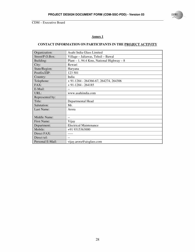
Annex 1
CONTACT INFORMATION ON PARTICIPANTS IN THE PROJECT ACTIVITY
Organization: Asahi India Glass Limited
Street/P.O.Box: Village – Jaliawas, Tehsil – Bawal
Building: Plant – 1, 94.4 Kms, National Highway – 8
City: Rewari
State/Region: Haryana
Postfix/ZIP: 123 501
Country: India
Telephone: + 91-1284 - 264366-67, 264274, 264306
FAX: + 91-1284 - 264185
E-Mail: --
URL: www.asahiindia.com
Represented by:
Title: Departmental Head
Salutation: Mr.
Last Name: Arora
Middle Name: --
First Name: Vijay
Department: Electrical Maintenance
Mobile: +91 9315363000
Direct FAX: -----
Direct tel: --
Personal E-Mail: [email protected]

PROJECT DESIGN DOCUMENT FORM (CDM-SSC-PDD) - Version 03
CDM – Executive Board
29
Annex 2
INFORMATION REGARDING PUBLIC FUNDING
• The project has not received any public funding and Official Development Assistance
(ODA).
� The project is an unilateral project.
PROJECT DESIGN DOCUMENT FORM (CDM-SSC-PDD) - Version 03
CDM – Executive Board
30
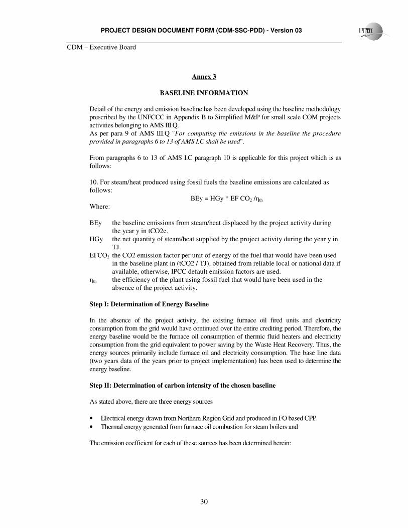
Annex 3
BASELINE INFORMATION
Detail of the energy and emission baseline has been developed using the baseline methodology
prescribed by the UNFCCC in Appendix B to Simplified M&P for small scale COM projects
activities belonging to AMS III.Q.
As per para 9 of AMS III.Q "For computing the emissions in the baseline the procedure
provided in paragraphs 6 to 13 of AMS I.C shall be used".
From paragraphs 6 to 13 of AMS I.C paragraph 10 is applicable for this project which is as
follows:
10. For steam/heat produced using fossil fuels the baseline emissions are calculated as
follows:
BEy = HGy * EF CO2 /ηth
Where:
BEy the baseline emissions from steam/heat displaced by the project activity during
the year y in tCO2e.
HGy the net quantity of steam/heat supplied by the project activity during the year y in
TJ.
EFCO2 the CO2 emission factor per unit of energy of the fuel that would have been used
in the baseline plant in (tCO2 / TJ), obtained from reliable local or national data if
available, otherwise, IPCC default emission factors are used.
ηth the efficiency of the plant using fossil fuel that would have been used in the
absence of the project activity.
Step I: Determination of Energy Baseline
In the absence of the project activity, the existing furnace oil fired units and electricity
consumption from the grid would have continued over the entire crediting period. Therefore, the
energy baseline would be the furnace oil consumption of thermic fluid heaters and electricity
consumption from the grid equivalent to power saving by the Waste Heat Recovery. Thus, the
energy sources primarily include furnace oil and electricity consumption. The base line data
(two years data of the years prior to project implementation) has been used to determine the
energy baseline.
Step II: Determination of carbon intensity of the chosen baseline
As stated above, there are three energy sources
• Electrical energy drawn from Northern Region Grid and produced in FO based CPP
• Thermal energy generated from furnace oil combustion for steam boilers and
The emission coefficient for each of these sources has been determined herein:

PROJECT DESIGN DOCUMENT FORM (CDM-SSC-PDD) - Version 03
CDM – Executive Board
31
(A) Emission Coefficient of the Northern Regional Grid
In the proposed baseline, Northern Region grid is used as the reference region for
estimating the current generation mix. Using the methodology available for small-scale
project activities, the weighted average emissions (t CO2 e/GWh) of current generation
mix of Northern Region grid of India is used for the calculation of baseline. The weighted
average emission factor data calculated and provided by Central Electricity Authority
(CEA)3 is used for the proposed project activity.
(B) Emission Coefficient for Furnace Oil (FO)
The emission coefficient is based on NCV and Emission Factor
As per the provisions of paragraph 59 of Appendix B of Simplified Modalities and Procedures
for Small Scale COM Project Activities [FCCC/CP/2002/7/Add.3, English, Page 21], the
emission coefficient (measured in kg of CO2 / kg of Furnace Oil) for the furnace oil reduced
had been calculated in accordance with the IPCC default values as well as the laboratory
analysis and stoichiometric analysis.
Emission Factors
The emission factors are based on IPCC Guidelines for National Greenhouse Gas Inventories and
are given below.
Fuel Emission Factor
(kg CO2/TJ)3
Emission factor
(kg CO2/kg)4
Calorific Value
(TJ/Gg)5
Residual Fuel Oil
(Furnace Oil)
77400 3.13 40.40
3 http://cea.nic.in/planning/c%20and%20e/Government%20of%20India%20website.htm

PROJECT DESIGN DOCUMENT FORM (CDM-SSC-PDD) - Version 03
CDM – Executive Board
32
Annex 4
MONITORING INFORMATION
Monitoring information has been detailed in the section B.7