clause 28 state machine test plan...the university of new hampshire interoperability laboratory...
TRANSCRIPT
© 2018 University of New Hampshire InterOperability Laboratory
ETHERNET
Clause 28 Auto-Negotiation
State Machine Base Page Exchange
Test Suite
v6.4
Technical Document
Last Updated: October 15, 2018 12:00pm
University of New Hampshire 22 Madbury Road, Suite 100
InterOperability Laboratory Durham, NH 03824
Ethernet Consortium Phone: (603) 862-0090
Fax: (603) 862-4181
https://www.iol.unh.edu/testing/ethernet/10gec
https://www.iol.unh.edu/testing/ethernet/fe
https://www.iol.unh.edu/testing/ethernet/ge

The University of New Hampshire
InterOperability Laboratory
ETHERNET TEST SUITE ii Auto-Negotiation State Machine Test Suite
MODIFICATION RECORD
• October 12, 2018 Version 6.4 Kathryn Dube: Updated procedure and observable results for the following tests:
Test #28.1.6: Link Fail Inhibit Timer
Test #28.1.7: Remote Fault Bit
• August 5, 2013 Version 6.3 Kathryn Dube: Updated procedure and observable results for the following test:
Test #28.4.4 - Link Integrity and RD Active
• July 2, 2010 Version 6.2 Matthew Senerchia: Updated all references to IEEE std. 803.3, 2008 Edition
• June 18, 2010 Version 6.1 Kyle Merkert: changed procedure for the following tests:
Test #28.2.6 – Acceptance of Long FLPs
• February 18, 2009 Version 6.0 Geoff Mitchell: Updated reference to IEEE std. 802.3an-2006.
• January 4, 2007 Version 5.9 Michael Ramsey: Modified: changed procedure and/or minor editorial changes to the following test:
Test#28.2.5 – Behavior with Incomplete FLPs
• November 22, 2006 Version 5.8 Geoff Mitchell: Modified: changed observable results and/or minor editorial changes to the following test:
Test #28.2.15 – Priority Resolution Function
• February 3, 2006 Version 5.7 Matthew Hersh: Modified: Updated reference to IEEE std. 802.3 – 2005.
• November 3, 2004 Version 5.6 Matthew Hersh: Modified: changed observable results and/or minor editorial changes to the following tests:
Test #28.1.3 – Transmit Link Code Word (Base Page) Encoding
Test #28.2.1 – Ability Match
Test #28.2.2 – Acknowledge Match
Test #28.2.3 – Consistency Match
Test #28.2.4 – Complete Acknowledge
Test #28.2.5 – Behavior with Incomplete FLPs
Test #28.2.6 – Acceptance of Long FLPs
Test #28.2.7 – Next Page and Remote Fault Bits
Test #28.2.8 – Selector Field Combinations
Test #28.2.9 – Technology Ability Field Bits
Test #28.2.10 – Identification of Link Partner as Auto-Negotiation Able
Test #28.2.11 – Range of NLP Timer
Test #28.2.12 – Range of FLP Timer
Test #28.2.13 – Range of Data Detect Timer
Test #28.2.14 – Transmit Disable
Test #28.4.4 – Link Integrity and RD Active
• October 14, 1996 Version 1.0 Initial Release
Previous versions of the test suite can be found at:
http://www.iol.unh.edu/services/testing/fe/testsuites/
The University of New Hampshire
InterOperability Laboratory
ETHERNET TEST SUITE iii Auto-Negotiation State Machine Test Suite
ACKNOWLEDGMENTS
The University of New Hampshire would like to acknowledge the efforts of the following individuals in the
development of this test suite.
Andy Baldman University of New Hampshire
Chris Bancroft University of New Hampshire
Kathryn Dube University of New Hampshire
Jerry Grand National Semiconductor
Matthew Hersh University of New Hampshire
Jeremy Kent University of New Hampshire
Jeff Lapak University of New Hampshire
Roy Lavender University of New Hampshire
Eric Lynskey University of New Hampshire
Kyle Merkert University of New Hampshire
Geoff Mitchell University of New Hampshire
Bob Noseworthy University of New Hampshire
Jake O'Dell University of New Hampshire
Ben Schultz University of New Hampshire
Matthew Senerchia University of New Hampshire
Karen Tuttle University of New Hampshire
Ben Verschueren University of New Hampshire
The University of New Hampshire
InterOperability Laboratory
ETHERNET TEST SUITE iv Auto-Negotiation State Machine Test Suite
INTRODUCTION
Overview
The University of New Hampshire’s InterOperability Laboratory (IOL) is an institution designed
to improve the interoperability of standards based products by providing an environment where a
product can be tested against other implementations of a standard. This suite of tests has been
developed to help implementers evaluate the functioning of their Clause 28 Auto-Negotiation
based products. The tests do not determine if a product conforms to the IEEE 802.3 Standard,
nor are they purely interoperability tests. Rather, they provide one method to isolate problems
within an auto-negotiating device. Successful completion of all tests contained in this suite does
not guarantee that the tested device will operate with other auto-negotiating devices. However,
combined with satisfactory operation in the IOL’s interoperability test bed, these tests provide a
reasonable level of confidence that the Device Under Test (DUT) will function well in most
auto-negotiating environments.
Organization of Tests
The tests contained in this document are organized to simplify the identification of information
related to a test and to facilitate in the actual testing process. Each test contains an identification
section that describes the test and provides cross-reference information. The discussion section
covers background information and specifies why the test is to be performed. Tests are grouped
in order to reduce setup time in the lab environment. Each test contains the following
information:
Test Number
The Test Number associated with each test follows a simple grouping structure. Listed first is
the Test Group Number followed by the test's number within the group. This allows for the
addition of future tests to the appropriate groups of the test suite without requiring the
renumbering of the subsequent tests.
Purpose
The purpose is a brief statement outlining what the test attempts to achieve. The test is written at
the functional level.
References
The references section lists cross-references to the IEEE 802.3 standards and other
documentation that might be helpful in understanding and evaluating the test and results.
Resource Requirements
The requirements section specifies the hardware, and test equipment that will be needed to
perform the test. The items contained in this section are special test devices or other facilities,
which may not be available on all devices.
Last Modification
The University of New Hampshire
InterOperability Laboratory
ETHERNET TEST SUITE v Auto-Negotiation State Machine Test Suite
This specifies the date of the last modification to this test.
Discussion
The discussion covers the assumptions made in the design or implementation of the test as well
as known limitations. Other items specific to the test are covered here.
Test Setup
The setup section describes the configuration of the test environment. Small changes in the
configuration should be included in the test procedure.
Procedure
The procedure section of the test description contains the step-by-step instructions for carrying
out the test. It provides a cookbook approach to testing, and may be interspersed with observable
results.
Observable Results
The observable results section lists observations that can be examined by the tester to verify that
the DUT is operating properly. When multiple values are possible for an observable, this section
provides a short discussion on how to interpret them. The determination of a pass or fail for a
certain test is often based on the successful (or unsuccessful) detection of a certain observable.
Possible Problems
This section contains a description of known issues with the test procedure, which may affect
test results in certain situations.
The University of New Hampshire
InterOperability Laboratory
ETHERNET TEST SUITE vi Auto-Negotiation State Machine Test Suite
TABLE OF CONTENTS
MODIFICATION RECORD .......................................................................................................... ii
ACKNOWLEDGMENTS ............................................................................................................. iii
INTRODUCTION ......................................................................................................................... iv
TABLE OF CONTENTS .............................................................................................................. vi
GROUP 1: BASE PAGE TRANSMISSION ................................................................................. 1
Test #28.1.1: Transmit Link Burst Timer ................................................................................... 2
Test #28.1.2: Interval Timer ....................................................................................................... 4
Test #28.1.3: Transmit Link Code Word (Base Page) Encoding ............................................... 5
Test #28.1.4: NLP Compliance .................................................................................................. 7
Test #28.1.5: Break Link Timer ................................................................................................. 9
Test #28.1.6: Link Fail Inhibit Timer ....................................................................................... 11
Test #28.1.7: Remote Fault Bit ................................................................................................. 13
Test #28.1.8: Failed Link for HCD ........................................................................................... 15
GROUP 2: BASE PAGE RECEPTION ....................................................................................... 16
Test #28.2.1: Ability Match ...................................................................................................... 17
Test #28.2.2: Acknowledge Match ........................................................................................... 19
Test #28.2.3: Consistency Match.............................................................................................. 21
Test #28.2.4: Complete Acknowledge ...................................................................................... 23
Test #28.2.5: Behavior with Incomplete FLPs ......................................................................... 24
Test #28.2.6: Acceptance of Long FLPs .................................................................................. 26
Test #28.2.7: Next Page and Remote Fault Bits ....................................................................... 28
Test #28.2.8: Selector Field Combinations ............................................................................... 30
Test #28.2.9: Technology Ability Field Bits ............................................................................ 32
Test #28.2.10: Identification of Link Partner as Auto-Negotiation Able ................................. 34
Test #28.2.11: Range of NLP Timer ........................................................................................ 35
Test #28.2.12: Range of FLP Test Timer ................................................................................. 37
Test #28.2.13: Range of Data Detect Timer ............................................................................. 39
Test #28.2.14: Transmit Disable State...................................................................................... 41
Test #28.2.15: Priority Resolution Function ............................................................................. 42
GROUP 3: PARALLEL DETECTION........................................................................................ 44
Test #28.3.1: Single Link Ready .............................................................................................. 45
Test #28.3.2: Range of Auto-Negotiation Wait Timer ............................................................. 46
GROUP 4: 10BASE-T RELATED TESTS.................................................................................. 48
Test #28.4.1: Link Count Max .................................................................................................. 49
Test #28.4.2: Range of Link Test Timers ................................................................................. 50
Test #28.4.3: Range of Link Loss Timer .................................................................................. 52
Test #28.4.4: Link Integrity and RD Active ............................................................................. 53

The University of New Hampshire
InterOperability Laboratory
ETHERNET TEST SUITE 1 Auto-Negotiation State Machine Test Suite
GROUP 1: BASE PAGE TRANSMISSION
Scope: The following tests cover Auto-Negotiation operation specific to the transmission of
Base Pages.
Overview: These tests are designed to verify that the device under tests transmits acceptable
Normal Link Pulses (NLPs), which are properly spaced, forming Fast Link Pulses (FLPs) with
acceptable content making up the Base Page transmitted by the device.

The University of New Hampshire
InterOperability Laboratory
ETHERNET TEST SUITE 2 Auto-Negotiation State Machine Test Suite
Test #28.1.1: Transmit Link Burst Timer
Purpose: To verify proper separation of consecutive fast link pulse (FLP) bursts.
References:
[1] IEEE Std. 802.3, 2008 Edition: subclause 28.3.2, Table 28-9, Figure 28-16, Transmit
state diagram.
Resource Requirements:
• Line Monitor: A system capable of detecting, time stamping, and recording normal link
pulses (NLPs) on both the receive and transmit channels of the DUT. The channel
signaling should pass through the Line Monitor with minimal distortion.
Last Modification: July 2, 2010
Discussion: A station capable of Auto-Negotiation must transmit fast link pulse (FLP) bursts.
Not only are the content and composition of these bursts important, but also the timing of the
bursts. This test is designed to verify that the timing of the device under test’s consecutive FLP
bursts fall within the specified range of 5.7 ms to 22.3 ms when extended Next Pages are not
supported. When extended Next Pages are supported the timer shall expire after 5.7 ms to 6.8
ms when transmitting 16-bit pages, and 1.3 ms to 3.1 ms when transmitting 48-bit pages.
Test Setup: Using a Cat 5 cable, connect the DUT’s transmitter to the Line Monitor. Terminate
the DUT’s transmit channel with a 100 line termination.
Procedure:
Part a:
1. Configure the DUT to send FLP bursts.
2. Monitor the transmitted bursts.
3. The separation of each burst is measured from the last NLP sent in an FLP to the first
NLP sent in the next FLP.
Part b – For devices that support extended Next Page transmission:
1. Use the Traffic Generator to send the DUT enough FLPs with the ACK, NP, and XNP
bits set to get the DUT to send extended Next Pages.
2. Monitor the transmitted extended Next Page bursts.
3. The separation of each burst is measure from the last NLP sent in an XNP to the first
NLP sent in the next XNP.
Observable Results: Device does not support extended Next Page and optimized timing
a. The separation of FLP bursts from the last NLP in an FLP to the first NLP in the next FLP must be
within the range of 5.7 ms to 22.3 ms.
b. The separation of FLP bursts from the first NLP in an FLP to the first NLP in the next FLP
must be within the range of 8 ms to 16 ms.
Device does support extended Next Page and optimized timing
The University of New Hampshire
InterOperability Laboratory
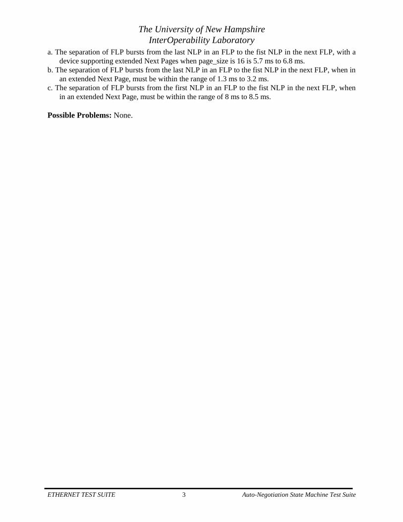
ETHERNET TEST SUITE 3 Auto-Negotiation State Machine Test Suite
a. The separation of FLP bursts from the last NLP in an FLP to the fist NLP in the next FLP, with a
device supporting extended Next Pages when page_size is 16 is 5.7 ms to 6.8 ms.
b. The separation of FLP bursts from the last NLP in an FLP to the fist NLP in the next FLP, when in
an extended Next Page, must be within the range of 1.3 ms to 3.2 ms.
c. The separation of FLP bursts from the first NLP in an FLP to the fist NLP in the next FLP, when
in an extended Next Page, must be within the range of 8 ms to 8.5 ms.
Possible Problems: None.
The University of New Hampshire
InterOperability Laboratory
ETHERNET TEST SUITE 4 Auto-Negotiation State Machine Test Suite
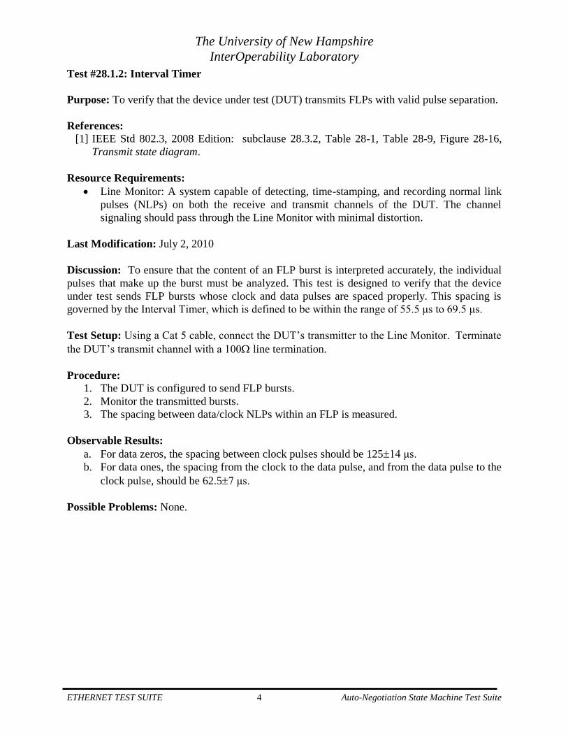
Test #28.1.2: Interval Timer
Purpose: To verify that the device under test (DUT) transmits FLPs with valid pulse separation.
References:
[1] IEEE Std 802.3, 2008 Edition: subclause 28.3.2, Table 28-1, Table 28-9, Figure 28-16,
Transmit state diagram.
Resource Requirements:
• Line Monitor: A system capable of detecting, time-stamping, and recording normal link
pulses (NLPs) on both the receive and transmit channels of the DUT. The channel
signaling should pass through the Line Monitor with minimal distortion.
Last Modification: July 2, 2010
Discussion: To ensure that the content of an FLP burst is interpreted accurately, the individual
pulses that make up the burst must be analyzed. This test is designed to verify that the device
under test sends FLP bursts whose clock and data pulses are spaced properly. This spacing is
governed by the Interval Timer, which is defined to be within the range of 55.5 μs to 69.5 μs.
Test Setup: Using a Cat 5 cable, connect the DUT’s transmitter to the Line Monitor. Terminate
the DUT’s transmit channel with a 100 line termination.
Procedure:
1. The DUT is configured to send FLP bursts.
2. Monitor the transmitted bursts.
3. The spacing between data/clock NLPs within an FLP is measured.
Observable Results:
a. For data zeros, the spacing between clock pulses should be 12514 μs.
b. For data ones, the spacing from the clock to the data pulse, and from the data pulse to the
clock pulse, should be 62.57 μs.
Possible Problems: None.

The University of New Hampshire
InterOperability Laboratory
ETHERNET TEST SUITE 5 Auto-Negotiation State Machine Test Suite
Test #28.1.3: Transmit Link Code Word (Base Page) Encoding
Purpose: To verify that the DUT transmits valid FLP data; including, an acceptable Selector
Field combination, advertises the correct abilities in the Technology Ability Field, and transmits
proper initial values for the Remote Fault, Acknowledge, and Next Page bits.
References:
[1] IEEE Std 802.3, 2008 Edition: subclauses 28.2.1.1.1, 28.2.1.2, 28.2.1.2.1, 28.2.1.2.2,
28.2.1.2.3, 28.2.1.2.4, 28.2.1.2.5, Annex 28A, 28B, 28B.1, 28B.2
Resource Requirements:
• Line Monitor: A system capable of detecting and recording normal link pulses (NLPs) on
both the receive and transmit channels of the DUT. The monitor should allow the NLPs
to pass through while minimally impacting the channel.
Last Modification: July 2, 2010
Discussion: This test is designed to verify that the device under test transmits Link Code Words
with acceptable content. There are defined Selector Field combinations that a station is permitted
to transmit in its Link Code Word. The Technology Ability Field of the Link Code Word
advertises a station’s abilities. The final three bits in the Link Code Word (Remote Fault bit,
Acknowledge bit, Next Page bit) should all have a proper initial setting. The default value for
the RF bit on a non-faulting link is zero. The ACK bit should be initially zero. The NP bit should
be one if the DUT supports Next Page exchange and zero if it does not, or does not wish to
implement a NP exchange. In this test, it is confirmed that the device under test transmits a Link
Code Word with the Selector Field combination corresponding to IEEE 802.3, advertises the
data service abilities that it supports in its Technology Ability Field, and has the RF, ACK, and
NP bits set correctly.
Test Setup: Using a Cat 5 cable, connect the DUT’s transmitter to the Line Monitor. Terminate
the DUT’s transmit channel with a 100 line termination.
Procedure:
1. The DUT is configured to send FLP bursts.
2. Monitor the transmitted bursts.
3. The number of pulses and the data present in several bursts is observed.
4. The contents of the Selector Field (first five data bits), Technology Ability Field
(D[12:5]), and of the Remote Fault bit, Acknowledge bit, and Next Page bit are acquired.
Observable Results:
a. The number of pulses in a burst should be 19-33 (inclusive).
b. The Selector Field combination should correspond to S[4:0]=00001 defined in Table
28A-1.
• The Technology Ability Field should advertise the proper abilities indicated in Table
28B-1.
• The DUT should not advertise any abilities that it does not possess.
• The initial value of the Remote Fault bit should be zero.

The University of New Hampshire
InterOperability Laboratory
ETHERNET TEST SUITE 6 Auto-Negotiation State Machine Test Suite
• The initial value of the Acknowledge bit should be zero.
• The value of the Next Page bit should be one if it supports Next Page exchange and
zero if it doesn’t or does not wish to implement a Next Page exchange. .
Possible Problems: None.

The University of New Hampshire
InterOperability Laboratory
ETHERNET TEST SUITE 7 Auto-Negotiation State Machine Test Suite
Test #28.1.4: NLP Compliance
Purpose: To verify the DUT’s link pulse waveforms meet specification.
References:
[1] IEEE Std 802.3, 2008 Edition: subclauses 14.3.1.2.1, 28.1.4.1, 28.2.1.1, 28.4, Table 55-
12, Figure 14-12, Transmitter waveform for link test pulse
[2] IEEE Std 1802.3d-1993: subclauses 6.3.4.8, 6.3.4.9
Resource Requirements:
• Oscilloscope: A digitizing signal analyzer, which meets or exceeds the specifications for
an oscilloscope, as defined in IEEE Std 1802.3d-1993 Section 6.3.4.8.
• Differential Voltage Probes: Meets or exceeds specifications defined in IEEE Std
1802.3d-1993 Section 6.3.4.9
• TP Test Card: A testing card with an RJ-45 interface, cable termination of Test Load 1,
or Test Load 2 (as defined in IEEE 802.3 Section 14.3.1.2.1 and Figure 14-11, Start-of-
TP_IDLE test load), and an Unshielded twisted pair model (as defined in IEEE Std 802.3
Section 14.3.1.2) that can be inserted inline.
• 55 m of Class E / Category 6: unscreened cable, 100 m of Class E / Category 6: screened
cable, 100 m of Class F cable, 100 m of Class Ea / Augmented Category 6 cable.
Last Modification: July 2, 2010
Discussion: All link pulses need to conform to the transmitter waveform specifications for Link
Test Pulses defined in IEEE Std 802.3, 2000 Ed. Figure 14-12, Transmitter waveform for link
test pulse, including those contained in an FLP burst, when measured across each of the test
loads defined in Figure 14-11; both with the load connected directly to the TD circuit and with
the load connected through all of the cable types and distances supported by the advertised
capabilities. For 10GBASE-T devices this corresponds to the Cables and lengths defined in
Table 55-12, which is shown on the next page. This test is designed to verify that the device
under test produces link pulses within specification.

The University of New Hampshire
InterOperability Laboratory
ETHERNET TEST SUITE 8 Auto-Negotiation State Machine Test Suite
Test Setup: Using one of the applicable cable types, as shown in the above table, connect the
DUT to the TP Test Card. Connect the Oscilloscope to the TP Test Card using Differential
Voltage Probes.
Procedure:
1. The DUT is configured to send FLP bursts.
2. Monitor the transmitted bursts.
3. Observe the link pulse waveforms across each test load defined in Figure 14-11, Start-of-
TP_IDLE test load.
4. Repeat procedure with loads connected through applicable cable types, as shown in the
above table.
Observable Results:
a. Under each test setup, the FLP’s link pulses should fit within the NLP template defined
in Figure 14-12, Transmitter waveform for link test pulse. After the differential output
voltage drops below -50 mV, it shall remain below +50 mV.
Possible Problems: None.
The University of New Hampshire
InterOperability Laboratory
ETHERNET TEST SUITE 9 Auto-Negotiation State Machine Test Suite
Test #28.1.5: Break Link Timer
Purpose: To verify that the DUT ceases transmission within the acceptable range.
References:
[1] IEEE Std 802.3, 2008 Edition: subclauses 28.2.3.2, 28.3
Resource Requirements:
• Line Monitor: A system capable of detecting, time stamping, and recording normal link
pulses (NLPs) on both the receive and transmit channels of the DUT. The channel
signaling should pass through the Line Monitor with minimal distortion.
• Traffic Generator: A system capable of generating and transmitting normal link pulses
(NLPs) and fast link pulses (FLPs) while connected to the receiver of the DUT.
Last Modification: July 2, 2010
Discussion: Once a device has entered the TRANSMIT DISABLE state, it must wait a
specified amount of time before it restarts the Auto-Negotiation process. This time is defined by
the device’s “break_link_timer,” and is required to be between 1200 and 1500 ms. This test is
designed to verify that the device under test restarts the Auto-Negotiation process after entering
the TRANSMIT DISABLE state within this range.
Test Setup: Using Cat 5 cables, connect the DUT and the Traffic Generator to the Line Monitor
such that the DUT’s receiver will see the Traffic Generator’s signaling. Terminate the DUT’s
transmit channel with a 100 line termination.
Procedure:
1. Establish a connection (not a link) to the DUT.
2. Use the Traffic Generator to put the DUT in the ACKNOWLEDGE DETECT state.
Send a series of 20 identical, validly formed FLP bursts without the ACK bit set. Once
reception of the FLP bursts cease, the DUT should enter the TRANSMIT DISABLE
state.
3. Verify that the DUT restarts Auto-Negotiation.
4. Measure the amount of time between when the DUT ceased FLP transmission (upon
entry of the TRANSMIT DISABLE state) and when the first FLP of the re-negotiation
process was transmitted. This time will be the value of break_link_timer plus any
additional gap due to partial completion of an FLP’s transmit_link_burst_timer.
5. Repeat steps 2-4 several times.
Observable Results:
a. Assuming a fixed value for the implemented break_link_timer, the minimum of the
observed gaps is the DUT’s break_link_timer, which should be in the range of 1200 to
1500 ms.
Possible Problems: If the DUT fails to enter the ACKNOWLEDGE DETECT state, the number
of FLPs sent may need to be increased (see Test #28.2.1: Ability Match) or the encoding of the
FLPs may need to be altered. If the DUT does not restart Auto-Negotiation due to a
flp_receive_idle=true while in ACKNOWLEDGE DETECT, then a consistency match error
The University of New Hampshire
InterOperability Laboratory
ETHERNET TEST SUITE 10 Auto-Negotiation State Machine Test Suite
could be sent to the DUT to try to cause an Auto-Negotiation restart (see Test #28.2.3:
Consistency Match). Else, resetting the DUT’s PHY and/or restarting Auto-Negotiation via
management should also produce a break_link_timer gap, measurable via the techniques
outlined above.

The University of New Hampshire
InterOperability Laboratory
ETHERNET TEST SUITE 11 Auto-Negotiation State Machine Test Suite
Test #28.1.6: Link Fail Inhibit Timer
Purpose: To verify that the DUT will defer for the proper amount of time before attempting to
verify the status of the link determined by the Auto-Negotiation process.
References:
[1] IEEE Std 802.3, 2018 Edition: subclauses 28.2.3.2, 28.3, Table 28-9
Resource Requirements:
• Line Monitor: A system capable of detecting, time stamping, and recording normal link
pulses (NLPs) on both the receive and transmit channels of the DUT. The channel
signaling should pass through the Line Monitor with minimal distortion.
• Traffic Generator: A system capable of generating and transmitting normal link pulses
(NLPs) and fast link pulses (FLPs) while connected to the receiver of the DUT.
Last Modification: July 2, 2010
Discussion: Once a device has entered the FLP LINK GOOD CHECK state, it must receive a
link_status=OK message from its link partner within a specified amount of time. If this message
is not received, it will enter the TRANSMIT DISABLE state and wait for the duration of its
break_link_timer before starting a re-negotiation. This time is defined by the device’s
“link_fail_inhibit_timer,” and is required to be between 750 and 1000 ms for devices not
operating at 10Gb/s, and 2000 – 2250 ms for devices operating at 10Gb/s. This test is designed
to verify that the device under test enters the TRANSMIT DISABLE state from the FLP LINK
GOOD CHECK state when a link_status=OK message is not received from its link partner in the
acceptable range of time.
Test Setup: Using Cat 5 cables, connect the DUT and the Traffic Generator to the Line Monitor
such that the DUT’s receiver will see the Traffic Generator’s signaling. Terminate the DUT’s
transmit channel with a 100 line termination.
Procedure:
Part a: for devices with a 10BASE-T PMA:
1. Establish a connection (not a link) to the DUT.
2. Use the Traffic Generator to put the device into the FLP LINK GOOD CHECK state and
resolve a 10BASE-T link by sending enough FLPs that advertise only 10BASE-T
abilities
3. Verify that the DUT restarts Auto-Negotiation.
4. Measure the amount of time NLPs are sent from the DUT and verify it is
link_fail_inhibit_timer.
Part b: for devices with a 100BASE-TX PMA:
5. Repeat steps 1-3 above, changing the advertised abilities to include 100BASE-TX
abilities.
6. Measure the amount of time the DUT was observed to source 100BASE-TX link
signaling.

The University of New Hampshire
InterOperability Laboratory
ETHERNET TEST SUITE 12 Auto-Negotiation State Machine Test Suite
Part c – for devices with a 1000BASE-T PMA:
7. Repeat steps 1-3 above, changing the advertised abilities, by means of a Next Page
exchange, to include 1000BASE-T abilities.
8. Measure the amount of time the DUT was observed to source 1000BASE-T link
signaling.
Part d – for devices with a 2.5GBASE-T PMA:
9. Repeat steps 1-3 above, changing the advertised abilities, by means of aa extended Next
Page exchange, to include 2.5GBASE-T abilities.
10. Measure the amount of time the DUT was observed to source 2.5GBASE-T link
signaling.
Part e – for devices with a 5GBASE-T PMA:
11. Repeat steps 1-3 above, changing the advertised abilities, by means of an extended Next
Page exchange, to include 5GgBASE-T abilities.
12. Measure the amount of time the DUT was observed to source 5GBASE-T link signaling.
Part f– for devices with a 10GBASE-T PMA:
13. Repeat steps 1-3 above, changing the advertised abilities, by means of an extended Next
Page exchange, to include 10GBASE-T abilities.
14. Measure the amount of time the DUT was observed to source 10GBASE-T link
signaling.
Observable Results:
a. For devices with a 10BASE-T PMA, observation of the interval between FLP cessation
and 10BASE-T link signaling cessation + transmit_link_burst_timer should be in the
range of 750 to 1000 ms.
b. For devices with a 100BASE-TX PMA, observation of the interval between FLP
cessation and 100BASE-TX link signaling cessation + transmit_link_burst_timer should
be in the range of 750 to 1000 ms.
c. For devices with a 1000BASE-T PMA, observation of the interval between FLP
cessation and 1000BASE-T link signaling cessation + transmit_link_burst_timer should
be in the range of 750 to 1000 ms.
d. For devices with a 2.5GBASE-T PMA, observation of the interval between FLP
cessation and 2.5GBASE-T link signaling cessation + transmit_link_burst_timer should
be in the range of 2000 to 2250 ms.
e. For devices with a 5GBASE-T PMA, observation of the interval between FLP cessation
and 5GBASE-T link signaling cessation + transmit_link_burst_timer should be in the
range of 2000 to 2250 ms.
f. For devices with a 10GBASE-T PMA, observation of the interval between FLP cessation
and 10GBASE-T link signaling cessation + transmit_link_burst_timer should be in the
range of 2000 to 2250 ms.
Possible Problems: None.
The University of New Hampshire
InterOperability Laboratory
ETHERNET TEST SUITE 13 Auto-Negotiation State Machine Test Suite
Test #28.1.7: Remote Fault Bit
Purpose: To verify that if the DUT implements the Remote Fault sensing function, the DUT
properly sets the Remote Fault bit in its Link Code Word. To verify that the Remote Fault bit
remains set until exiting the FLP LINK GOOD state and restarting Auto-Negotiation.
References:
[1] IEEE Std 802.3, 2008 Edition: subclause 28.2.1.2, 28.2.3.5, Table 45-124
Resource Requirements:
• Line Monitor: A system capable of detecting, time stamping, and recording normal link
pulses (NLPs) on both the receive and transmit channels of the DUT. The channel
signaling should pass through the Line Monitor with minimal distortion.
• Traffic Generator: A system capable of generating and transmitting normal link pulses
(NLPs) and fast link pulses (FLPs) while connected to the receiver of the DUT.
Last Modification: July 2, 2010
Discussion: A device that elects to support the Remote Fault sensing function must set the
Remote Fault bit in its base page advertisements once a fault condition has occurred. The
Remote Fault bit in register 4 (or 7.16 for devices supporting 2.5GBASE-T or higher) is a
read/write bit and must be transmitted in the Base Page as it is written in the register. Once the
Remote Fault bit is written, it must remain set until the device enters the FLP LINK GOOD
state, ensuring that the link partner receives the fault indication. This test verifies that the device
will set its Remote Fault bit when a fault condition occurs (for devices that support the Remote
Fault sensing function), and that the base page continues to advertise the Remote Fault
indication until the device enters the FLP LINK GOOD state.
Test Setup: Using Cat 5 cables, connect the DUT and the Traffic Generator to the Line Monitor
such that the DUT’s receiver will see the Traffic Generator’s signaling. Terminate the DUT’s
transmit channel with a 100 line termination.
Procedure:
Part a: Device supports the Remote Fault sensing function
1. Cause the DUT to indicate a remote fault by any means.
2. Observe transmissions from the DUT.
Part b: Setting the Remote Fault bit with either bit 4.13 or bit 7.16.13
3. Write bit 4.13 (for non-MultiGBASE-T devices) or bit 7.16.13 (for MultiGBASE-T
devices).
4. Restart Auto-Negotiation.
5. Observe transmissions from the DUT.
Part c: Setting the Remote Fault bit to zero
6. Cause the DUT to set its Remote Fault bit.
7. Establish a link with the DUT.
The University of New Hampshire
InterOperability Laboratory
ETHERNET TEST SUITE 14 Auto-Negotiation State Machine Test Suite
8. Break the link and observe transmissions from the DUT.
Observable Results:
a. The DUT should have the Remote Fault bit set in all FLPs that are transmitted.
b. The DUT should have the Remote Fault bit set in all FLPs that are transmitted.
c. The DUT should have the Remote Fault bit set to zero after the link was broken.
Possible Problems: If the Remote Fault sensing function is not supported, part a cannot be
performed. If register access is not provided, part b cannot be performed. If neither part a nor
part b can be performed, part c cannot be performed.

The University of New Hampshire
InterOperability Laboratory
ETHERNET TEST SUITE 15 Auto-Negotiation State Machine Test Suite
Test #28.1.8: Failed Link for HCD
Purpose: To verify that the DUT starts a re-negotiation upon the reception of a
link_status=FAIL from the resolved highest common denominator (HCD) technology.
References:
[1] IEEE Std 802.3, 2008 Edition: subclause 28.2.3.2
Resource Requirements:
• Line Monitor: A system capable of detecting, time-stamping, and recording normal link
pulses (NLPs) on both the receive and transmit channels of the DUT. The channel
signaling should pass through the Line Monitor with minimal distortion.
• Traffic Generator: A system capable of generating and transmitting normal link pulses
(NLPs) and fast link pulses (FLPs) as well as valid link signaling and frames for
10/100/1000BASE-T and recording received frames while connected to the receiver of
the DUT.
Last Modification: July 2, 2010
Discussion: Once the highest common denominator (HCD) technology has been determined
through the Parallel Detection Function, if a station receives a link_status=FAIL message from
that priority, it should cause a re-negotiation. This test is designed to verify that the device under
test does start a re-negotiation upon the receipt of a link_status=FAIL message from the HCD
technology.
Test Setup: Using Cat 5 cables, connect the DUT and the Traffic Generator to the Line Monitor
such that the DUT’s receiver will see the Traffic Generator’s signaling. Terminate the DUT’s
transmit channel with a 100 line termination.
Procedure:
1. Use the Traffic Generator to send a series of FLP bursts that advertise a set of abilities
compatible with the DUT.
2. Verify the DUT resolves the HCD and establishes a valid link.
3. Break the link to the Traffic Generator, leaving the Line Monitor attached to the DUT,
thus causing the DUT to see a link_status=FAIL for the HCD link.
4. Verify that the DUT starts a re-negotiation.
Observable Results:
a. Upon reception of the link_status=FAIL message, the DUT should disable all
transmission for approximately break_link_timer and restart Auto-Negotiation.
Possible Problems: None.

The University of New Hampshire
InterOperability Laboratory
ETHERNET TEST SUITE 16 Auto-Negotiation State Machine Test Suite
GROUP 2: BASE PAGE RECEPTION
Scope: The following tests cover Auto-Negotiation operation specific to the reception of Base
Pages.
Overview: These tests are designed to verify that the device under tests reacts properly to the
receipt of both valid and invalid fast link pulse (FLP) bursts.
The University of New Hampshire
InterOperability Laboratory
ETHERNET TEST SUITE 17 Auto-Negotiation State Machine Test Suite
Test #28.2.1: Ability Match
Purpose: To verify that the DUT enters the ACKNOWLEDGE DETECT state upon reception
of complete, consecutive, and consistent FLP bursts, ignoring the value of the Acknowledge bit.
References:
[1] IEEE Std 802.3, 2008 Edition: subclauses 28.2.1.2, 28.1.4.2, 28.2.1.2.4
Resource Requirements:
• Line Monitor: A system capable of detecting, time-stamping, and recording normal link
pulses (NLPs) on both the receive and transmit channels of the DUT. The channel
signaling should pass through the Line Monitor with minimal distortion.
• Traffic Generator: A system capable of generating and transmitting normal link pulses
(NLPs) and fast link pulses (FLPs) while connected to the receiver of the DUT.
Last Modification: July 2, 2010
Discussion: Once an auto-negotiating device identifies its link partner as Auto-Negotiation
able, it will enter the ACKNOWLEDGE DETECT state only after it receives at least 3 complete,
consecutive and consistent Link Code Words from its link partner, ignoring the Acknowledge
bit. Once the ACKNOWLEDGE DETECT state is entered, the station should send out FLP
bursts containing its Link Code Word with the Acknowledge bit (the fifteenth data pulse) set to
logic one. This test is designed to verify that the device under test will set the Acknowledge bit
after the reception of 3 or more complete, consecutive and consistent Link Code Words.
Test Setup: Using Cat 5 cables, connect the DUT and the Traffic Generator to the Line Monitor
such that the DUT’s receiver will see the Traffic Generator’s signaling. Terminate the DUT’s
transmit channel with a 100 line termination.
Procedure:
Part a:
1. Use the Traffic Generator to send 1 FLP to the DUT.
2. Monitor the FLPs sent back by the DUT and determine whether the Acknowledge bit is
set.
3. If it was not set, repeat steps 1 and 2 increasing the number (n) of FLPs until the
Acknowledge bit is set by the DUT.
4. Send (n) FLPs to DUT all with the Acknowledge bit set to logic one, where (n) is the
minimum number of FLPs determined in step 3 to put the DUT into the
ACKNOWLEDGE DETECT state.
5. Repeat step 4 using FLPs that have Acknowledge bits that alternate between 1 and 0.
Part b:
6. Use the Traffic Generator to send (n) FLPs, alternating between an initial FLP and a
valid FLP containing different advertised abilities, such that the number of FLPs would
be enough to put the DUT into the ACKNOWLEDGE DETECT state.
The University of New Hampshire
InterOperability Laboratory
ETHERNET TEST SUITE 18 Auto-Negotiation State Machine Test Suite
7. Monitor the FLPs sent back by the DUT and determine whether the Acknowledge bit is
set.
8. Repeat steps 6-7 by sending all combinations of FLPs that are one bit different than the
initial FLP.
Part c:
9. Using the Traffic Generator, send the DUT the following sequence: one FLP, followed
by one NLP, followed by (n-2) FLPs; where all the FLPs in the series are identical.
10. Repeat step 9 varying the number of NLPs sent to the DUT while maintaining a total of
(n) pulses.
Part d:
11. Send a series of FLPs designed to put the DUT in the ACKNOWLEDGE DETECT state.
12. Monitor the FLPs sent from the DUT after returning to the ABILITY DETECT state and
determine whether the Acknowledge bit is set.
Observable Results:
a. The Acknowledge bit should be set after the reception of at least 4 complete and
matching FLPs, regardless of the value of the Acknowledge bit. Record the number of
FLPs required to put the DUT into the ACKNOWLEDGE DETECT state for use in later
tests.
b. The DUT should not enter the ACKNOWLEDGE DETECT state and thus the
Acknowledge bit should never be set.
c. The DUT should not enter the ACKNOWLEDGE DETECT state and thus the
Acknowledge bit should never be set.
d. Upon returning to the ABILITY DETECT state, the DUT should reset to its default Base
Page and send FLPs without the Acknowledge bit set.
Possible Problems: None.
The University of New Hampshire
InterOperability Laboratory
ETHERNET TEST SUITE 19 Auto-Negotiation State Machine Test Suite
Test #28.2.2: Acknowledge Match
Purpose: To verify that the DUT enters the COMPLETE ACKNOWLEDGE state only after
receiving three consecutive and consistent FLPs with the Acknowledge bit set.
References:
[1] IEEE Std 802.3, 2008 Edition: subclause 28.2.1.2.4
Resource Requirements:
• Line Monitor: A system capable of detecting, time stamping, and recording normal link
pulses (NLPs) on both the receive and transmit channels of the DUT. The channel
signaling should pass through the Line Monitor with minimal distortion.
• Traffic Generator: A system capable of generating and transmitting normal link pulses
(NLPs) and fast link pulses (FLPs) while connected to the receiver of the DUT.
Last Modification: July 2, 2010
Discussion: A station reaches the COMPLETE ACKNOWLEDGE state after first entering the
ACKNOWLEDGE DETECT state (which is done when at least 3 complete, consecutive and
consistent FLP bursts are received, ignoring the Acknowledge bit, - see Test #28.2.1: Ability
Match), and then receiving 3 complete, consecutive and consistent FLPs with the Acknowledge
bit set. This test is designed to verify that the device under test requires the reception of 3
consecutive and consistent FLPs with the Acknowledge bit set before doing entering the
COMPLETE ACKNOWLEDGE state.
Test Setup: Using Cat 5 cables, connect the DUT and the Traffic Generator to the Line Monitor
such that the DUT’s receiver will see the Traffic Generator’s signaling. Terminate the DUT’s
transmit channel with a 100 line termination.
Procedure:
Part a:
1. Use the Traffic Generator to send a series of (n) FLPs with the Acknowledge bit not set
followed by (m) FLPs with the Acknowledge bit set to logic one but otherwise identical
to the initial FLPs. (n) is the value found in test #28.2.1 to cause the DUT to enter the
ACKNOWLEDGE DETECT state. (m) is initially set to one.
2. Observe transmissions from the DUT.
3. Repeat steps 1-2 increasing (m), until the DUT is observed to enter into the COMPLETE
ACKNOWLEDGE state.
Part b:
4. Use the Traffic Generator to send two groups of FLPs. The first group consists of (n)
FLPs with the Acknowledge bit not set. The second group consists of (2*m) FLPs that
alternate between FLPs identical to the first group, and FLPs that are one bit different
from the first group; however, all FLPs in this group have the Acknowledge bit set.
5. Repeat step 4 using all one bit different FLPs.

The University of New Hampshire
InterOperability Laboratory
ETHERNET TEST SUITE 20 Auto-Negotiation State Machine Test Suite
Part c:
6. Using the Traffic Generator send the DUT two series of FLPs. The first group consists
of (n) valid FLPs. The second group is comprised of the following pattern: FLP with
ACK, followed by one NLP, followed by FLPs with ACK until (m) is reached. All the
FLPs in the second group are identical to the first group with the exception of the
Acknowledge bit.
7. Repeat step 6 increasing the amount of NLPs sent, but never exceeding (m).
Observable Results:
a. The DUT should enter the COMPLETE ACKNOWLEDGE state after receiving three
FLPs with the Acknowledge bit set to logic one.
b. The DUT should never enter the COMPLETE ACKNOWLEDGE state, and should send
out FLPs with the Acknowledge bit set until nlp_test_max_timer expires. Following the
FLPs should be a gap of ‘break_link_timer’ until FLP transmission resumes.
c. The DUT should never enter the COMPLETE ACKNOWLEDGE state, and should send
out FLPs with the Acknowledge bit set until nlp_test_max_timer expires. Following the
FLPs should be a gap of ‘break_link_timer’ until FLP transmission resumes.
Note: Observing if the DUT has previously entered the COMPLETE ACKNOWLEDGE state
can be most easily accomplished by any of three methods. First, by observing that the DUT has
transmitted 6-8 FLPs after receiving the test sequence, followed by observing the transmission
of a Next Page, if a Next Page exchange is required. By observing the transmission of the
highest common denominator link signaling, if a link is to be established. Or timing the
cessation of FLP transmission to the resumption of FLP transmission if a link is to be
established, but no link signaling is provided to the DUT. In this last case, the gap should be
link_fail_inhibit_timer + break_link_timer.
Possible Problems: None.
The University of New Hampshire
InterOperability Laboratory
ETHERNET TEST SUITE 21 Auto-Negotiation State Machine Test Suite
Test #28.2.3: Consistency Match
Purpose: To verify that the DUT performs a consistency match test on received FLPs.
References:
[1] IEEE Std 802.3, 2008 Edition: subclause 28.3.1
Resource Requirements:
• Line Monitor: A system capable of detecting, time stamping, and recording normal link
pulses (NLPs) on both the receive and transmit channels of the DUT. The channel
signaling should pass through the Line Monitor with minimal distortion.
• Traffic Generator: A system capable of generating and transmitting normal link pulses
(NLPs) and fast link pulses (FLPs) while connected to the receiver of the DUT.
Last Modification: July 2, 2010
Discussion: Upon entering the ACKNOWLEDGE DETECT state of the Auto-Negotiation
process, a device must receive 3 consecutive and consistent FLPs from its link partner before it
can proceed. However, these FLPs must not only be consistent amongst themselves, but also
with the FLPs that the device received to put it into the ACKNOWLEDGE DETECT state. To
ensure this, a station must perform a consistency match test. If a consistency mismatch occurs,
the device should enter the TRANSMIT DISABLE state and cease sending FLPs. This test is
designed to verify that the device under test checks that the FLPs received in the
ACKNOWLEDGE DETECT state are consistent (ignoring the Acknowledge bit) with the FLPs
that it received to get it there.
Test Setup: Using Cat 5 cables, connect the DUT and the Traffic Generator to the Line Monitor
such that the DUT’s receiver will see the Traffic Generator’s signaling. Terminate the DUT’s
transmit channel with a 100 line termination.
Procedure:
Part a:
1. Use the Traffic Generator to send two groups of FLPs. The first group consists of (n)
FLPs with the Acknowledge bit not set. The second group consists of (m) FLPs that are
one bit different from the first group, but all FLPs in this group have the Acknowledge
bit set. (n) is the value found in test #28.2.1 to cause the DUT to enter the
ACKNOWLEDGE DETECT state, and (m) is the value found in test #28.2.2.
2. Monitor the transmit line coming from the DUT.
3. Repeat steps 1-2 toggling all bits of the FLPs, except the ACK bit.
Part b: Minimum number of FLPs to complete Auto-Negotiation:
4. Use the Traffic Generator to send (n) FLPs all with the Acknowledge bit set to cause the
DUT to enter the ACKNOWLEDGE DETECT state.
5. Monitor the transmit line coming from the DUT.
6. Repeat steps 4-5 increasing the number of FLPs sent until the DUT is observed to enter
the COMPLETE ACKNOWLEDGE state.

The University of New Hampshire
InterOperability Laboratory
ETHERNET TEST SUITE 22 Auto-Negotiation State Machine Test Suite
Part c:
7. Using the Traffic Generator send two groups of FLPs to the DUT. The first group
consists of (n) valid FLPs. The second group consists of (m) FLPs and NLPs, where all
the FLPs are one bit different but still have the Acknowledge bit set.
Observable Results:
a. The DUT should ‘immediately’ cease transmitting FLPs once the inconsistent FLPs are
received.
b. The DUT should enter COMPLETE ACKNOWLEDGE after reception of 4, 5, 6, or 7
FLPs with the ACK bit set.
c. The DUT should cease transmitting FLPs once the inconsistent FLPs are received.
Possible Problems: None.

The University of New Hampshire
InterOperability Laboratory
ETHERNET TEST SUITE 23 Auto-Negotiation State Machine Test Suite
Test #28.2.4: Complete Acknowledge
Purpose: To verify that the DUT sends out a valid number of Link Code Words after the
COMPLETE ACKNOWLEDGE state has been entered.
References:
[1] IEEE Std 802.3, 2008 Edition: subclauses 28.2.1.2.4, 28.3.1, 28.3.4, Figure 28-18,
Arbitration state diagram
Resource Requirements:
• Line Monitor: A system capable of detecting, time stamping, and recording normal link
pulses (NLPs) on both the receive and transmit channels of the DUT. The channel
signaling should pass through the Line Monitor with minimal distortion.
• Traffic Generator: A system capable of generating and transmitting normal link pulses
(NLPs) and fast link pulses (FLPs) while connected to the receiver of the DUT.
Last Modification: July 2, 2010
Discussion: A station reaches the COMPLETE ACKNOWLEDGE state after first entering the
ACKNOWLEDGE DETECT state (which is done when at least 3 complete, consecutive and
consistent FLP bursts are received, ignoring the Acknowledge bit- see Test #28.2.1: Ability
Match), and then receiving 3 complete, consecutive and consistent FLPs with the Acknowledge
bit set. Once the COMPLETE ACKNOWLEDGE state has been entered, a station should send
out 6 to 8 (inclusive) more FLPs containing its Link Code Word with the Acknowledge bit set to
one. This test is designed to verify that the device under test sends out 6 to 8 (inclusive) FLPs
after entering the COMPLETE ACKNOWLEDGE state.
Test Setup: Using Cat 5 cables, connect the DUT and the Traffic Generator to the Line Monitor
such that the DUT’s receiver will see the Traffic Generator’s signaling. Terminate the DUT’s
transmit channel with a 100 line termination.
Procedure:
1. Establish a connection (not a link) to the DUT.
2. Use the Traffic Generator to send a series of (n) FLPs with the Acknowledge bit not set,
followed by (m) FLPs with the Acknowledge bit set to logic one, to put the DUT into the
COMPLETE ACKNOWLEDGE state.
3. Monitor the transmit line coming from the DUT and count the number of FLPs sent by
the DUT after the COMPLETE ACKNOWLEDGE state has been entered.
Observable Results:
a. After COMPLETE ACKNOWLEDGE state has been entered, the DUT should send out
6 to 8 (inclusive) FLPs containing its Link Code Word. Following the FLPs should be a
gap of link_fail_inhibit_timer + break_link_timer until FLP transmission resumes.
Possible Problems: None.

The University of New Hampshire
InterOperability Laboratory
ETHERNET TEST SUITE 24 Auto-Negotiation State Machine Test Suite
Test #28.2.5: Behavior with Incomplete FLPs
Purpose: To observe the DUT’s behavior upon receipt of incomplete FLP bursts.
References:
[1] IEEE Std 802.3, 2008 Edition: subclauses 28.2.1.2, 28.3.1, Figure 28-7, Base Page
encoding, Figure 28-17, Receive state diagram
Resource Requirements:
• Line Monitor: A system capable of detecting, time-stamping, and recording normal link
pulses (NLPs) on both the receive and transmit channels of the DUT. The channel
signaling should pass through the Line Monitor with minimal distortion.
• Traffic Generator: A system capable of generating and transmitting normal link pulses
(NLPs) and fast link pulses (FLPs) while connected to the receiver of the DUT.
Last Modification: July 2, 2010
Discussion: This test identifies how a given implementation chooses to handle FLPs with less
than 16 data positions. While Figure 28-15, Receive state diagram, will accept incomplete FLPs
without error, a difficulty in interpretation lies with the definition of ‘ability_match’ in 28.3.1.
Here it is stated that the Acknowledge bit will be set upon reception of three matching
consecutive Link Code Words. While subclause 28.2.1.2 and Figure 28-7, Base Page encoding,
suggest a Link Code Word is 16 bits, but this is not stated explicitly. Thus, if one interprets a
Link Code Word to be 16 bits (or greater, refer to Test #28.2.6: Acceptance of Long FLPs), then
any FLP containing less than 16 data positions would be ignored as such a short FLP would not
be used in the ability_match function. Alternatively, if a Link Code Word is interpreted to mean
any length bit-vector, then any short/incomplete FLP must be used in an ability_match. This
would allow for the possibility of ability_match being set to true upon receipt of three matching
consecutive, but short, FLPs. While such a scenario would undoubtedly present problems, the
likelihood seems small. A benefit gained through such an approach may be increased robustness
as incomplete FLPs resulting from error conditions and/or line noise will not be ignored by the
Auto-Negotiating device, as is the case in the first case.
Test Setup: Using Cat 5 cables, connect the DUT and the Traffic Generator to the Line Monitor
such that the DUT’s receiver will see the Traffic Generator’s signaling. Terminate the DUT’s
transmit channel with a 100 line termination.
Procedure:
Part a:
1. Establish a connection (not a link) to the DUT.
2. Use a Traffic Generator to send the DUT enough incomplete FLPs, consisting of only 10
clock pulses and spaced so that the time to send (n) FLPs is larger than
nlp_test_max_timer, to put the DUT into the ACKNOWELDGE DETECT state.
3. Observe whether the DUT entered the ACKNOWLEDGE DETECT state.
The University of New Hampshire
InterOperability Laboratory
ETHERNET TEST SUITE 25 Auto-Negotiation State Machine Test Suite
Part b: (Informative)
4. Establish a connection (not a link) to the DUT.
5. Use a Traffic Generator to send the DUT enough incomplete FLPs consisting of only 11
clock pulses and spaced so that the time to send (n) FLPs is larger than
nlp_test_max_timer, to put the DUT into the ACKNOWLEDGE DETECT state.
6. Observe whether the DUT entered the ACKNOWLEDGE DETECT state.
7. Repeat steps 4-6, incrementing the number of data bits until the DUT is observed to enter
the ACKNOWLEDGE DETECT state.
Part c:
8. Establish a connection (not a link) to the DUT.
9. Use a Traffic Generator to send the DUT a series of the following 2 FLPs alternating at
16 ms apart: a 17 pulse FLP containing the following data: 10000111101 with no clock
pulse after the final logic one data pulse, and an 8 pulse FLP containing the following
data: 10010 with a final clock pulse.
10. Observe whether the DUT entered the Acknowledge Detect state.
Observable Results:
a. The DUT should not enter the ACKNOWLEDGE DETECT state.
b. As mentioned in the discussion above, a DUT may or may not enter the
ACKNOWLEDGE DETECT state when the number of data bits is less than 16,
corresponding to 17 clock pulses. The number of clock pulses at which the DUT enters
the ACKNOWLEDGE DETECT state is the rx_bit_cnt_check value. This value needs
to lie between 10 and 17.
c. The DUT should not enter the ACKNOWLEDGE DETECT state.
Possible Problems: None.

The University of New Hampshire
InterOperability Laboratory
ETHERNET TEST SUITE 26 Auto-Negotiation State Machine Test Suite
Test #28.2.6: Acceptance of Long FLPs
Purpose: To verify that the DUT properly accepts FLPs with more than 16 data positions by
ignoring all but the first 16 data bits.
References:
[1] IEEE Std 802.3, 2008 Edition: subclauses 28.2.2, 28.2.2.1, 28.3.3, Figure 28-17 Receive
state diagram
Resource Requirements:
• Line Monitor: A system capable of detecting, time-stamping, and recording normal link
pulses (NLPs) on both the receive and transmit channels of the DUT. The channel
signaling should pass through the Line Monitor with minimal distortion.
• Traffic Generator: A system capable of generating and transmitting normal link pulses
(NLPs) and fast link pulses (FLPs) while connected to the receiver of the DUT.
Last Modification: July 2, 2010
Discussion: An FLP burst normally consists of 17 to 33 pulses, with normally 16 data bits.An
extended Next Page FLP Burst normally consists of 49 to 97 pulses, with normally 48 data bits.
However, if a device receives an FLP with more than 16 (or 48) data positions, it should still
accept the burst. The first 16 (or 48) data bits should be kept and any additional should be
ignored. This test is designed to determine whether the Device Under Test properly accepts
FLPs with more than 16 (or 48) data bits.
Test Setup: Using Cat 5 cables, connect the DUT and the Traffic Generator to the Line Monitor
such that the DUT’s receiver will see the Traffic Generator’s signaling. Terminate the DUT’s
transmit channel with a 100 line termination.
Procedure:
Part a:
1. Use a Traffic Generator to send enough valid FLPs with 1 extra data position
corresponding to a logic one (1 extra clock pulse and 1 data pulse) attached to the end to
put the DUT into the Acknowledge Detect state.
2. Observe whether the DUT enters the ACKNOWLEDGE DETECT state.
3. Repeat steps 1 and 2, using extended Next Pages, if necessary.
Part b:
4. Repeat steps 1 and 2 above, alternating between normal FLPs and identical FLPs with 5
additional data bits corresponding to 10001.
5. Repeat step 4 using extended Next Pages, if necessary.
Observable Results:
a. The DUT should enter the ACKNOWLEDGE DETECT state.
b. The DUT should enter the ACKNOWLEDGE DETECT state.

The University of New Hampshire
InterOperability Laboratory
ETHERNET TEST SUITE 27 Auto-Negotiation State Machine Test Suite
Possible Problems: None.

The University of New Hampshire
InterOperability Laboratory
ETHERNET TEST SUITE 28 Auto-Negotiation State Machine Test Suite
Test #28.2.7: Next Page, Remote Fault, and XNP Bits
Purpose: To verify that the DUT can handle the reception of an FLP from a Next Page capable
device, an extended Next Page capable device, as well as the reception of a flagged Remote
Fault bit.
References:
[1] IEEE Std 802.3, 2008 Edition: subclauses 28.2.1.2, 28.2.1.2.3, 28.2.1.2.4, 28.2.1.2.5,
28.2.3.4, 28.2.3.5
Resource Requirements:
• Line Monitor: A system capable of detecting, time stamping, and recording normal link
pulses (NLPs) on both the receive and transmit channels of the DUT. The channel
signaling should pass through the Line Monitor with minimal distortion.
• Traffic Generator: A system capable of generating and transmitting normal link pulses
(NLPs) and fast link pulses (FLPs) while connected to the receiver of the DUT.
Last Modification: July 2, 2010
Discussion: When a station is connected to a Next Page able device, it will receive FLP bursts
with set Next Page bits (the final bit of the Link Code Words set to logic one). Regardless of
whether the receiving station is Next Page able or not, it should still accept the Link Code Word
as valid. The same is also true of extended Next Page capability. When connected to any
station, it is possible for a device to receive logic one in the Remote Fault (RF) bit position (bit
D13) of the Link Code Word. If a device supports the Remote Fault Function, the only defined
behavior is to set the Remote Fault bit in the MII status register. Other than that, there is no
specification as to what action a device should take upon reception of a remote fault. This test is
designed to verify that the device under test is capable of receiving a flagged Next Page,
extended Next Page and/or Remote Fault bits.
Test Setup: Using Cat 5 cables, connect the DUT and the Traffic Generator to the Line Monitor
such that the DUT’s receiver will see the Traffic Generator’s signaling. Terminate the DUT’s
transmit channel with a 100 line termination.
Procedure:
Part a:
1. Establish a connection (not a link) to the DUT.
2. Use the Traffic Generator to send (n) FLPs with the Acknowledge bit not set, and (m)
FLPs with the Acknowledge bit set, all with the Next Page bit set to logic one to put it
into the COMPLETE ACKNOWLEDGE state.
3. Verify that the DUT enters the COMPLETE ACKNOWLEDGE state.
Part b:
4. Repeat steps 1-3, with FLPs with the Remote Fault bit set to logic one.
Part c:

The University of New Hampshire
InterOperability Laboratory
ETHERNET TEST SUITE 29 Auto-Negotiation State Machine Test Suite
5. Repeat steps 1-3, with FLPs with the extended Next Page bit set to logic one.
Observable Results:
a. The DUT should enter the COMPLETE ACKNOWLEDGE state.
b. The DUT should enter the COMPLETE ACKNOWLEDGE state. If the DUT supports
the Remote Fault Function, then the DUT should set the Remote Fault bit in its MII
status register, and any other behavior is unpredictable.
c. The DUT should enter the COMPLETE ACKNOWLEDGE state.
Possible Problems: None.
The University of New Hampshire
InterOperability Laboratory
ETHERNET TEST SUITE 30 Auto-Negotiation State Machine Test Suite
Test #28.2.8: Selector Field Combinations
Purpose: To verify that the DUT accepts FLPs with the Selector Field set to a reserved
combination or any other defined combination.
References:
[1] IEEE Std 802.3, 2008 Edition: subclauses 28.2.1.2, 28.2.1.2.1, 28.3.1, Annex 28A, 28B,
28B.1
Resource Requirements:
• Line Monitor: A system capable of detecting, time stamping, and recording normal link
pulses (NLPs) on both the receive and transmit channels of the DUT. The channel
signaling should pass through the Line Monitor with minimal distortion.
• Traffic Generator: A system capable of generating and transmitting normal link pulses
(NLPs) and fast link pulses (FLPs) while connected to the receiver of the DUT.
Last Modification: July 2, 2010
Discussion: There are Selector Field combinations that are reserved by the IEEE. A station is
never supposed to transmit these combinations, but there are no specifications as to the
combinations that can be received. Therefore, as long as complete and consistent Link Code
Words are received, a station should accept them as valid regardless of the Selector Field
combination. This test is designed to verify that the device under test will accept a Link Code
Word with the Selector Field set to a reserved combination. A second Selector Field combination
has been defined as Isochronous Ethernet (01000). A third Selector Field combination has been
defined as IEEE-802.5 Token Ring (11000).
Test Setup: Using Cat 5 cables, connect the DUT and the Traffic Generator to the Line Monitor
such that the DUT’s receiver will see the Traffic Generator’s signaling. Terminate the DUT’s
transmit channel with a 100 line termination.
Procedure:
Part a: ACKNOWLEDGE DETECT with different Selector Field combinations
1. Establish a connection (not a link) to the DUT.
2. Use the Traffic Generator to send (n) FLPs with the Acknowledge bit not set, and with
Selector Field combinations of 00000b, 11000b(IEEE 802.5), 11111b, and 01000b(IEEE
802.9) (ordered bit S0 to S4) to put the DUT into the ACKNOWLEDGE DETECT state.
Verify that the DUT enters the ACKNOWLEDGE DETECT state.
Part b: COMPLETE ACKNOWLEDGE with different Selector Field combinations
3. Use the Traffic Generator to send (n) FLPs with the Acknowledge bit not set, and (m)
FLPs with the Acknowledge bit set, all with Selector Field combinations of 00000b,
11000b, 11111b, and 01000b (ordered bit S0 to S4) to put the DUT into the COMPLETE
ACKNOWLEDGE state.
Observable Results:
The University of New Hampshire
InterOperability Laboratory
ETHERNET TEST SUITE 31 Auto-Negotiation State Machine Test Suite
a. The DUT should enter the ACKNOWLEDGE DETECT state.
b. The DUT should enter the COMPLETE ACKNOWLEDGE state.
Possible Problems: None.

The University of New Hampshire
InterOperability Laboratory
ETHERNET TEST SUITE 32 Auto-Negotiation State Machine Test Suite
Test #28.2.9: Technology Ability Field Bits
Purpose: To verify that the DUT accepts FLPs with different combinations of the Technology
Ability Field bits set to logic one.
References:
[1] IEEE Std 802.3, 2008 Edition: subclauses 28.2.1.2, 28.2.1.2.2, 28.2.3.3, Annex 28B.2
Resource Requirements:
• Line Monitor: A system capable of detecting, time-stamping, and recording normal link
pulses (NLPs) on both the receive and transmit channels of the DUT. The channel
signaling should pass through the Line Monitor with minimal distortion.
• Traffic Generator: A system capable of generating and transmitting normal link pulses
(NLPs) and fast link pulses (FLPs) while connected to the receiver of the DUT.
Last Modification: July 2, 2010
Discussion: The technology ability field contains eight bits that indicate supported technologies
specific to the Selector Field value. Bits A0:A6 are encoded as 10BASE-T half duplex,
10BASE-T full duplex, 100BASE-TX half duplex, 100BASE-TX full duplex, 100BASE-T4,
PAUSE, and Asymmetric PAUSE operation for full duplex links, respectively. The IEEE
currently reserves the last bit of the Link Code Word’s Technology Ability Field. A station is
supposed to transmit this bit as logic zero. Regardless of what abilities a device advertises, it is
supposed to be able to receive any of the technology ability field bits set to a one without
affecting normal operation. This test is designed to verify that the device under test will accept a
Link Code Word with various combinations of the technology ability field set to logic one.
Test Setup: Using a Cat 5 cable, connect the DUT’s transmitter to the Line Monitor. Terminate
the DUT’s transmit channel with a 100 line termination. Using a Cat 5 cable, connect the
DUT’s receiver to the Traffic Generator using a 100 line termination.
Procedure:
Part a:
1. Establish a connection (not a link) to the DUT.
2. Use the Traffic Generator to send (n) FLPs with the Acknowledge bit not set and bit A0
set to logic one to put it into the ACKNOWLEDGE DETECT state.
3. Verify that the DUT enters the ACKNOWLEDGE DETECT state.
4. Repeat steps 1-3 but send FLPs encoded with bit combinations set to logic one including
A1, A2, A3, A4, A5, and A6.
Part b:
5. Use the Traffic Generator to send (n) FLPs with the Acknowledge bit not set, and (m)
FLPs with the Acknowledge bit set to put the DUT into the COMPLETE
ACKNOWLEDGE state.
6. Verify that the DUT enters the COMPLETE ACKNOWLEDGE state.

The University of New Hampshire
InterOperability Laboratory
ETHERNET TEST SUITE 33 Auto-Negotiation State Machine Test Suite
7. Repeat step 5 but send FLPs encoded with all possible one bit differences.
Observable Results:
a. The DUT should enter the ACKNOWLEDGE DETECT state regardless of the received
FLPs encoded with varying Technology Ability Field bits.
b. The DUT should enter the COMPLETE ACKNOWLEDGE state regardless of the
received FLPs encoded with varying Technology Ability Field bits.
Possible Problems: None.

The University of New Hampshire
InterOperability Laboratory
ETHERNET TEST SUITE 34 Auto-Negotiation State Machine Test Suite
Test #28.2.10: Identification of Link Partner as Auto-Negotiation Able
Purpose: To verify that the DUT is able to recognize its link partner as capable of Auto-
Negotiation within specification.
References:
[1] IEEE Std 802.3, 2008 Edition: subclause 28.2.2.1, Figure 28-17 Receive state diagram.
Resource Requirements:
• Line Monitor: A system capable of detecting, time-stamping, and recording normal link
pulses (NLPs) on both the receive and transmit channels of the DUT. The channel
signaling should pass through the Line Monitor with minimal distortion.
• Traffic Generator: A system capable of generating and transmitting normal link pulses
(NLPs) and fast link pulses (FLPs) while connected to the receiver of the DUT.
Last Modification: July 2, 2010
Discussion: When establishing a link, a station is required to recognize its link partner as Auto-
Negotiation able within a certain range of pulses in an FLP burst. This test is designed to verify
that the device under test adheres to this range. As determined from Figure 28-15 - Receive state
diagram, flp_cnt is determined to be 1 less than the number of pulses required to recognize its
link partner as Auto-Negotiation able.
Test Setup: Using a Cat 5 cable, connect the DUT’s transmitter to the Line Monitor. Terminate
the DUT’s transmit channel with a 100 line termination. Using a Cat 5 cable, connect the
DUT’s receiver to the Traffic Generator using a 100 line termination.
Procedure:
1. Establish a connection (not a link) to the DUT.
2. Use a Traffic Generator to send the DUT pulses (beginning with one pulse) spaced at 50
s, wait 16 ms, then send enough valid FLP bursts to put the DUT into the
ACKNOWLEDGE DETECT state. The proper number of FLP bursts should be (n) – 1,
as that value includes the FLP required to identify a device as Auto-Negotiation able.
3. Determine whether the DUT has entered the ACKNOWLEDGE DETECT state.
4. If the DUT did not enter the ACKNOWLEDGE DETECT state, repeat steps 1-3
increasing the number of initial pulses until the DUT enters the ACKNOWLEDGE
DETECT state.
Observable Results:
a. The DUT should recognize the Link Partner as Auto-Negotiation able within 7 to 18
(inclusive) pulses. Flp_cnt is one less than this determined number.
Possible Problems: None.
The University of New Hampshire
InterOperability Laboratory
ETHERNET TEST SUITE 35 Auto-Negotiation State Machine Test Suite
Test #28.2.11: Range of NLP Timer
Purpose: To verify that the DUT accepts FLP bursts with proper spacing, and refuses those
with spacing outside of the acceptable range.
References:
[1] IEEE Std 802.3, 2008 Edition: subclauses 28.2.2.1, 28.3.2
Resource Requirements
• Line Monitor: A system capable of detecting, time-stamping, and recording normal link
pulses (NLPs) on both the receive and transmit channels of the DUT. The channel
signaling should pass through the Line Monitor with minimal distortion.
• Traffic Generator: A system capable of generating and transmitting normal link pulses
(NLPs) and fast link pulses (FLPs) while connected to the receiver of the DUT.
Last Modification: July 2, 2010
Discussion: As well as characteristic requirements, FLP bursts have requirements for the delay
between consecutive bursts. In order to be accepted as valid, received FLP bursts must have a
delay between them between “nlp_test_min_timer” and “nlp_test_max_timer.” The non-
optimized value for “nlp_test_min_timer” must be between 5 and 7 ms. The optimized value for
“nlp_test_min_timer” must be between 6.75 and 7.25 ms. The value for “nlp_test_max_timer”
must be between 50 and 150 ms. This test is to verify that the device under test accepts FLP
bursts with spacing within these ranges, and refuses FLP bursts with spacing outside of these
ranges. Note, “nlp_test_min_timer” is measured from the beginning of an FLP to the beginning
of the next FLP, whereas “nlp_test_max_timer” is measured from the end of an FLP to the
beginning of the next FLP.
Test Setup: Using a Cat 5 cable, connect the DUT’s transmitter to the Line Monitor. Terminate
the DUT’s transmit channel with a 100 line termination. Using a Cat 5 cable, connect the
DUT’s receiver to the Traffic Generator using a 100 line termination.
Procedure:
Part a: nlp_test_min_timer
1. Establish a connection (not a link) to the DUT.
2. Use a Traffic Generator to send the DUT (n) FLPs with the Acknowledge bit not set
spaced between 2 ms and 10 ms to put it into the ACKNOWLEDGE DETECT state.
3. Observe whether the DUT entered the ACKNOWLEDGE DETECT state.
4. Repeat steps 1-3 varying the spacing of the FLPs until the range at which the DUT enters
the ACKNOWLEDGE DETECT state and does not enter the ACKNOWLEDGE
DETECT state is found.

The University of New Hampshire
InterOperability Laboratory
ETHERNET TEST SUITE 36 Auto-Negotiation State Machine Test Suite
Part b: nlp_test_max_timer
5. Repeat steps 1-3 varying the spacing of the FLPs starting between 30 ms and 200 ms,
until the range at which DUT enters the ACKNOWLEDGE DETECT state and does not
enter the ACKNOWLEDGE DETECT state is found.
Observable Results:
a. The nlp_test_min_timer should lie between 5 ms and 7 ms for devices using non-
optimized timing. The nlp_test_min_timer should lie between 6.75 ms and 7.25 ms for
devices using optimized timing.
b. The nlp_test_max_timer should lay between 50 ms and 150 ms.
Possible Problems: None.

The University of New Hampshire
InterOperability Laboratory
ETHERNET TEST SUITE 37 Auto-Negotiation State Machine Test Suite
Test #28.2.12: Range of FLP Test Timer
Purpose: To verify that the DUT determines that its link partner is Auto-Negotiation able upon
receiving pulses spaced within flp_test_min_timer and flp_test_max_timer, and does not
recognize a device as Auto-Negotiation able upon receiving pulses spaced outside the acceptable
range.
References:
[1] IEEE Std 802.3, 2008 Edition: subclauses 28.2.2.1, 28.3.2, Figure 28-17 Receive state
diagram
Resource Requirements:
• Line Monitor: A system capable of detecting, time-stamping, and recording normal link
pulses (NLPs) on both the receive and transmit channels of the DUT. The channel
signaling should pass through the Line Monitor with minimal distortion.
• Traffic Generator: A system capable of generating and transmitting normal link pulses
(NLPs) and fast link pulses (FLPs) while connected to the receiver of the DUT.
Last Modification: July 2, 2010
Discussion: As well as characteristic requirements, FLP bursts have requirements for the delay
between consecutive pulses within the burst. In order to be accepted as valid, received pulses
must have a delay between them between “flp_test_min_timer” and “flp_test_max_timer.” The
value for “flp_test_min_timer” must be between 5 and 25 s. The value for
“flp_test_max_timer” must be between 165 and 185 s. This test is to verify that the device
under test accepts FLP bursts with pulses spaced within these ranges, and refuses FLPs with
pulses spaced outside of these ranges.
Test Setup: Using Cat 5 cables, connect the DUT and the Traffic Generator to the Line Monitor
such that the DUT’s receiver will see the Traffic Generator’s signaling. Terminate the DUT’s
transmit channel with a 100 line termination.
Procedure:
Part a: flp_test_min_timer
1. Establish a connection (not a link) to the DUT.
2. Use a Traffic Generator to send the DUT enough pulses spaced at 5 s to identify the
link partner as Auto-Negotiation able (refer to Test #28.2.10: Identification of Link
Partner as Auto-Negotiation Able), wait 16 ms, then send (n) – 1 valid FLP bursts to put
the DUT into the ACKNOWLEDGE DETECT state.
3. Observe whether the DUT entered the ACKNOWLEDGE DETECT state.
4. Repeat steps 1-3 varying the pulse spacing until the DUT enters ACKNOWLEDGE
DETECT state.

The University of New Hampshire
InterOperability Laboratory
ETHERNET TEST SUITE 38 Auto-Negotiation State Machine Test Suite
Part b: flp_test_max_timer
5. Repeat steps 1-3 varying the pulse spacing, starting at 185 s until the DUT enters the
ACKNOWLEDGE DETECT state.
Observable Results:
a. The flp_test_min_timer should lay between 5 s and 25 s.
b. The flp_test_max_timer should lay between 165 s and 185 s.
Possible Problems: None.

The University of New Hampshire
InterOperability Laboratory
ETHERNET TEST SUITE 39 Auto-Negotiation State Machine Test Suite
Test #28.2.13: Range of Data Detect Timer
Purpose: To verify that the DUT accepts data pulses with proper spacing and refuses data
pulses with spacing outside the acceptable range.
References:
[1] IEEE Std 802.3, 2008 Edition: subclauses 28.2.2.1, 28.3.2, Figure 28-17 Receive state
diagram
Resource Requirements:
• Line Monitor: A system capable of detecting, time-stamping, and recording normal link
pulses (NLPs) on both the receive and transmit channels of the DUT. The channel
signaling should pass through the Line Monitor with minimal distortion.
• Traffic Generator: A system capable of generating and transmitting normal link pulses
(NLPs) and fast link pulses (FLPs) while connected to the receiver of the DUT.
Last Modification: July 2, 2010
Discussion: As well as characteristic requirements, FLP bursts have requirements for the delay
between clock and data pulses within the burst. In order to be accepted as valid, received data
pulses must have a delay between them and the previous clock pulse between
“data_detect_min_timer” and “data_detect_max_timer.” The value for “data_detect_min_timer”
must be between 15 and 47 s. The value for “data_detect_max_timer” must be between 78 and
100 s. This test is designed to verify that the device under test accepts FLP bursts with data
pulses spaced within these ranges, and ignores FLPs with data pulses spaced outside of these
ranges. As defined in Figure 28-15, Receive State diagram, if an FLP containing the data
pattern 1,0 is sent with the data 1 transmitted a time exceeding 100 s following the clock pulse,
then the data_detect_max_timer should be violated. In a conformant device, this should result
in the interpretation of the data pattern as 0,1. Thus, by alternating the transmission of this test
FLP with FLPs containing typical spacing, a conformant device should not enter the
ACKNOWLEDGE DETECT state. This technique is used to test the validity of
data_detect_max_timer.
Test Setup: Using Cat 5 cables, connect the DUT and the Traffic Generator to the Line Monitor
such that the DUT’s receiver will see the Traffic Generator’s signaling. Terminate the DUT’s
transmit channel with a 100 line termination.
Procedure:
Part a: data_detect_min_timer
1. Establish a connection (not a link) to the DUT.
2. Use the Traffic Generator to send the DUT (n) FLPs, alternating between FLPs with the
first data pulse spaced 15 s from the clock pulse and FLPs with nominal spacing, to put
it into the ACKNOWLEDGE DETECT state.
3. Observe whether the DUT entered the ACKNOWLEDGE DETECT state.
The University of New Hampshire
InterOperability Laboratory
ETHERNET TEST SUITE 40 Auto-Negotiation State Machine Test Suite
4. Repeat steps 1-3, varying the gap from the clock pulse to the data pulse until the DUT
enters the ACKNOWLEDGE DETECT state.
Part b: data_detect_max_timer
5. Repeat steps 1 3, varying the gap from the clock pulse to the data pulse, starting at 100
s, until the DUT enters the ACKNOWLEDGE DETECT state.
Part c: ignoring pulses below data_detect_min_timer
6. Repeat steps 1-3, changing the FLP to contain two “data” pulses, one before the
implemented data_detect_min_timer is finished, and another after the
data_detect_min_timer is finished. (The time between the clock and the first data pulse
should be the same as the time between the two data pulses).
Observable Results:
a. The data_detect_min_timer should lay between 15 s and 47 s.
b. The data_detect_max_timer should lay between 78 s and 100 s.
c. The DUT should ignore the first data pulse and decode the second data pulse as logic one
causing the DUT to enter the ACKNOWLEDGE DETECT State.
Possible Problems: None.

The University of New Hampshire
InterOperability Laboratory
ETHERNET TEST SUITE 41 Auto-Negotiation State Machine Test Suite
Test #28.2.14: Transmit Disable State
Purpose: To verify that the DUT enters the ABILITY DETECT state upon completion of
break_link_timer from the TRANSMIT DISABLE state.
References:
[1] IEEE Std 802.3, 2008 Edition: subclauses 28.2.1.2, 28.1.4.2, 28.2.1.2.4
Resource Requirements:
• Line Monitor: A system capable of detecting, time-stamping, and recording normal link
pulses (NLPs) on both the receive and transmit channels of the DUT. The channel
signaling should pass through the Line Monitor with minimal distortion.
• Traffic Generator: A system capable of generating and transmitting normal link pulses
(NLPs) and fast link pulses (FLPs) while connected to the receiver of the DUT.
Last Modification: July 2, 2010
Discussion: Once an Auto-Negotiating device enters the TRANSMIT DISABLE state, it should
stop transmission for break_link_timer before it re-enters the ABILITY DETECT state.
However, there is no specification as to whether the DUT’s receiver has to be turned off in the
TRANSMIT DISABLE state. If a sequence of FLPs designed to cause an Auto-Negotiating
station to enter the ACKNOWLEDGE DETECT state is sent to the DUT during Transmit
Disable, acknowledge detect can be set to true. However, once break_link_timer is finished, the
DUT will enter the ABILITY DETECT state where acknowledge detect is reset to false. Thus,
the DUT will need to get another ability match once it enters the ABILITY DETECT state.
Test Setup: Using a Cat 5 cable, connect the DUT’s transmitter to the Line Monitor. Terminate
the DUT’s transmit channel with a 100 line termination. Using a Cat 5 cable, connect the
DUT’s receiver to the Traffic Generator using a 100 line termination.
Procedure:
1. Establish a connection (not a link) to the DUT.
2. Use the Traffic Generator to send a series of (n) FLPs designed to cause the DUT to
enter the ACKNOWLEDGE DETECT state.
3. Once the DUT halts its FLP transmission, send the same sequence of FLPs at periodic
intervals less than break_link_timer.
4. Monitor the DUT’s FLP transmission during this process.
Observable Results:
a. The DUT should resume FLP transmission after break_link_timer is finished, regardless
of the received FLPs during the time where the DUT was in the TRANSMIT DISABLE
state.
Possible Problems: None.

The University of New Hampshire
InterOperability Laboratory
ETHERNET TEST SUITE 42 Auto-Negotiation State Machine Test Suite
Test #28.2.15: Priority Resolution Function
Purpose: To verify that the device under test properly configures the highest common
denominator (HCD) technology for the transmitted technologies in a link code word.
References:
[1] IEEE Std 802.3, 2008 Edition: subclause 28.2.3.3, Annex 28.B.2, 28B.3
Resource Requirements:
• Line Monitor: A system capable of detecting, time-stamping, and recording normal link
pulses (NLPs) on both the receive and transmit channels of the DUT. The channel
signaling should pass through the line monitor with minimal distortion.
• NLP Generator: A system capable of generating and transmitting normal link pulses
(NLPs) and fast link pulses (FLPs) while connected to the receiver of the DUT.
Last Modification: July 2, 2010
Discussion: Once a station has received its link partner’s link code word and completed the
exchange of FLP bursts, the technology at which communication is to be established must be
resolved. Through the priority resolution function, the highest common denominator (HCD)
technology should be found. Upon reception of a non-Ethernet selector field it is recommended
that a device disable all Ethernet PMAs, as it could cause problems with a non-Ethernet link
partner. This test is designed to verify that the device under test resolves the proper HCD for all
possible technology and selector field combinations.
Test Setup: Using Cat 5 cables, connect the DUT and the NLP Generator to the Line Monitor
such that the Traffic Generator’s signaling will be seen by the DUT’s receiver. Terminate the
DUT’s transmit channel with a 100 line termination.
Procedure:
Part a: Ethernet Selector Field Resolution
1. Establish a connection (not a link) to the DUT.
2. Use the Traffic Generator to send a series of FLP bursts that advertise a set of abilities with
an Ethernet selector field.
3. Verify that the DUT establishes a link when it can, and refuses a link otherwise.
4. Verify that the DUT resolved the highest common technology by sending a packet to the
DUT in that format and determining whether it was received.
5. Verify that full duplex was resolved whenever possible.
6. Repeat this procedure for all possible combinations of the first five bits of the technology
ability field.
Part b: Non- Ethernet Selector Field Resolution
7. Repeat steps 1-6 with Base Pages advertising selector fields other than 802.3.

The University of New Hampshire
InterOperability Laboratory
ETHERNET TEST SUITE 43 Auto-Negotiation State Machine Test Suite
Observable Results:
a. In every case, the DUT should resolve a link at the highest priority possible based on the
priority resolution function for the technologies advertised.
b. INFORMATIVE: The DUT should enter the FLP LINK GOOD CHECK state and it is
recommended that it disable all Ethernet PMAs.
Possible Problems: None

The University of New Hampshire
InterOperability Laboratory
ETHERNET TEST SUITE 44 Auto-Negotiation State Machine Test Suite
GROUP 3: PARALLEL DETECTION
Scope: The following tests cover Auto-Negotiation operation specific to the Parallel Detection
mechanism.
Overview: These tests are designed to verify that an auto-negotiating device can properly detect
a legacy (non-auto-negotiating) fixed speed device.

The University of New Hampshire
InterOperability Laboratory
ETHERNET TEST SUITE 45 Auto-Negotiation State Machine Test Suite
Test #28.3.1: Single Link Ready
Purpose: To verify that the DUT properly monitors the status of single_link_ready during
Parallel Detection.
References:
[1] IEEE Std 802.3, 2008 Edition: subclause 28.3.4, Figure 28-18, Arbitration state
diagram, Figure 28-19, NLP Receive Link Integrity Test state diagram
Resource Requirements:
• Line Monitor: A system capable of detecting, time-stamping, and recording normal link
pulses (NLPs) on both the receive and transmit channels of the DUT. The channel
signaling should pass through the Line Monitor with minimal distortion.
• Traffic Generator: A system capable of generating and transmitting normal link pulses
(NLPs) and fast link pulses (FLPs) while connected to the receiver of the DUT.
Last Modification: July 2, 2010
Discussion: When a device implementing a 10BASE-T PMA begins to receive link test pulses
it must indicate link_status[NLP]=READY after ‘lc_max’ number of pulses have been received.
According to Figure 28-16, Arbitration state diagram, once link_status[NLP]=READY is
indicated, the device should cease transmitting FLPs and start autoneg_wait_timer.
Single_link_ready is then used to indicate if exactly one PMA is currently ready. If no link is
ready or if more than a single link is simultaneously ready then single_link_ready=false,
mr_parallel_detection_fault=true, and FLP transmission should resume “immediately”. This test
is designed to verify that the process described above functions appropriately.
Test Setup: Using a Cat 5 cable, connect the DUT’s transmitter to the Line Monitor. Terminate
the DUT’s transmit channel with a 100 line termination. Using a Cat 5 cable, connect the
DUT’s receiver to the Traffic Generator using a 100 line termination.
Procedure:
1. Establish a connection (not a link) to the DUT.
2. Use a Traffic Generator to send the DUT ‘lc_max’ pulses spaced at 16 ms.
3. Determine the duration for which the DUT has ceased transmitting FLPs.
Observable Results:
a. The DUT should cease FLP transmission for approximately link_loss_timer +
transmit_link_burst_timer.
Possible Problems: None.

The University of New Hampshire
InterOperability Laboratory
ETHERNET TEST SUITE 46 Auto-Negotiation State Machine Test Suite
Test #28.3.2: Range of Auto-Negotiation Wait Timer
Purpose: To verify that the implemented value of autoneg_wait_timer is within the specified
range of 500 to 1000 ms.
References:
[1] IEEE Std 802.3, 2008 Edition: subclause 28.3.4, Figure 28-18, Arbitration state diagram
Resource Requirements:
• Line Monitor: A system capable of detecting, time-stamping, and recording normal link
pulses (NLPs) on both the receive and transmit channels of the DUT. The channel
signaling should pass through the Line Monitor with minimal distortion.
• Traffic Generator: A system capable of generating and transmitting normal link pulses
(NLPs) and fast link pulses (FLPs) while connected to the receiver of the DUT.
Last Modification: July 2, 2010
Discussion: In order for an Auto-Negotiation able device to properly parallel detect a link
partner, it must receive a valid single_link_ready=true signal from its link partner for a period of
time before it negotiates to that link. This time is defined by the device’s “autoneg_wait_timer,”
and is specified to be between 500 and 1000 ms. This test is designed to verify that the DUT
does not parallel detect to a link before waiting a time within this range. This timer cannot be
measured precisely from the RJ-45 interface; however, it can be bounded. The upper bound can
be established by causing a single link to be ready and observing the gap between cessation of
FLPs and commencement of the link pulses/stream. This delay includes any inter-FLP gap that
the device may be in the midst of when detection of single_link_ready occurs. Additionally, any
delay from the proper link being enabled to actual signaling appearing on the line will add to the
value of the observed gap. The lower bound may be established for devices implementing a
10BASE-T PMA by first determining the implemented values of lc_max and link_loss_timer.
With these values known, the DUT can be sent a burst of link test pulses corresponding to
lc_max plus the duration of autoneg_wait_timer found for the upper bound. The number of
pulses in the burst may then be decreased until the DUT is observed to source FLPs following
reception of the pulses, instead of NLPs (10BASE-T link). This transition identifies the range of
the lower bound. This range should be autoneg_wait_timer minus the time required to detect
single_link_ready=false.
Test Setup: Using a Cat 5 cable, connect the DUT’s transmitter to the Line Monitor. Terminate
the DUT’s transmit channel with a 100 line termination. Using a Cat 5 cable, connect the
DUT’s receiver to the Traffic Generator using a 100 line termination.
Procedure:
1. Establish a connection (not a link) to the DUT.
2. Use a Traffic Generator to send the station valid NLPs continuously with valid spacing.
3. Monitor the DUT’s transmit line.
4. Verify that the DUT establishes a 10BASE-T link.

The University of New Hampshire
InterOperability Laboratory
ETHERNET TEST SUITE 47 Auto-Negotiation State Machine Test Suite
5. Measure the time between when the DUT ceased transmission of FLPs and when the
DUT began transmitting NLPs. The minimum of these observations is the upper bound
of autoneg_wait_timer.
6. Break link, and calculate the number of NLPs to send to satisfy: X*NLP_gap = upper
bound of autoneg_wait_timer.
7. Send X + lc_max NLPs at a gap of ‘NLP_gap’ to the DUT.
8. Repeat step 7, decreasing X until the DUT sources FLPs following cessation of the NLPs
from the Traffic Generator (the gap should be approximately link_loss_timer).
Observable Results:
a. The DUT’s autoneg_wait_timer should be in the range of 500 to 1000 ms.
Possible Problems: If only the upper or lower bound lies outside the conformance window, then
the autoneg_wait_timer cannot be found conformant or non-conformant.

The University of New Hampshire
InterOperability Laboratory
ETHERNET TEST SUITE 48 Auto-Negotiation State Machine Test Suite
GROUP 4: 10BASE-T RELATED TESTS
Scope: The following tests cover 10BASE-T operation specific to the NLP Receive Link
Integrity Test state diagram.
Overview: These tests are designed to verify the operation of the NLP Receive Link Integrity
Test state diagram for 10BASE-T devices. This state machine was introduced in Clause 28
replacing the previously defined Link Integrity Test Function state Diagram of Figure 14-6, Link
Integrity Test function state diagram, in Clause 14 of IEEE 802.3. The primary motivation for
this change was to prevent an Auto-Negotiation capable 10BASE-T device from detecting a link
when non-10BASE-T frames (such as 100BASE-TX idle) were received.
NOTE: THESE TESTS CANNOT BE PERFORMED IF THE DUT DOES NOT SUPPORT A
10BASE-T PMA.

The University of New Hampshire
InterOperability Laboratory
ETHERNET TEST SUITE 49 Auto-Negotiation State Machine Test Suite
Test #28.4.1: Link Count Max
Purpose: To verify that the DUT implements lc_max within 2 to 10 link test pulses.
References:
[1] IEEE Std 802.3, 2005 Edition: subclauses 14.2.3.1, 28.3.4, Figure 14-12, Transmitter
waveform for link test pulse, Figure 28-18, Arbitration state diagram, Figure 28-19, NLP
Receive Link Integrity Test state diagram
Resource Requirements:
• Line Monitor: A system capable of detecting, time-stamping, and recording normal link
pulses (NLPs) on both the receive and transmit channels of the DUT. The channel
signaling should pass through the Line Monitor with minimal distortion.
• Traffic Generator: A system capable of generating and transmitting normal link pulses
(NLPs) and fast link pulses (FLPs) while connected to the receiver of the DUT.
Last Modification: July 2, 2010
Discussion: When a device implementing a 10BASE-T PMA begins to receive link test pulses
conformant to Figure 14-12, Transmitter waveform for link test pulse, it must indicate
link_status[NLP]=READY after ‘lc_max’ number of pulses have been received. According to
Figure 28-16, Arbitration state diagram, once link_status[NLP]=READY is indicated, the
device should cease transmitting FLPs. To prevent a device from indicating link off a received
FLP, the state machine depicted in Figure 28-17, NLP Receive Link Integrity Test state diagram,
resets if a pulse is received before the link_test_min_timer has expired. This test is designed to
verify that the implemented value of lc_max is between 2 and 10 pulses (inclusive).
Test Setup: Using a Cat 5 cable, connect the DUT’s transmitter to the Line Monitor. Terminate
the DUT’s transmit channel with a 100 line termination. Using a Cat 5 cable, connect the
DUT’s receiver to the Traffic Generator using a 100 line termination.
Procedure:
1. Establish a connection (not a link) to the DUT.
2. Use a Traffic Generator to send the DUT 2 pulses spaced at 16 ms.
3. Determine whether the DUT has ceased transmitting FLPs.
4. If the DUT did not cease FLP transmission, repeat steps 1-3 varying the number of pulses
sent until the DUT ceases FLP transmission.
Observable Results:
a. The DUT should cease FLP transmission for approximately link_loss_timer after
receiving between 2 to 10 link test pulses.
Possible Problems: None.
The University of New Hampshire
InterOperability Laboratory
ETHERNET TEST SUITE 50 Auto-Negotiation State Machine Test Suite
Test #28.4.2: Range of Link Test Timers
Purpose: To verify that the DUT accepts NLPs (link test pulses) with proper spacing, and
refuses those with spacing outside of the acceptable range.
References:
[1] IEEE Std 802.3, 2008 Edition: subclauses 14.2.1.7, 28.3.4, Figure 28-18, Arbitration
state diagram
Resource Requirements
• Line Monitor: A system capable of detecting, time-stamping, and recording normal link
pulses (NLPs) on both the receive and transmit channels of the DUT. The channel
signaling should pass through the Line Monitor with minimal distortion.
• Traffic Generator: A system capable of generating and transmitting normal link pulses
(NLPs) and fast link pulses (FLPs) while connected to the receiver of the DUT.
Last Modification: July 2, 2010
Discussion: The acceptable gap between NLPs (10BASE-T link test pulses) is defined to be
between “link_test_min_timer” and “link_test_max_timer.” The value for “link_test_min_timer”
must be between 2 and 7 ms. The value for “link_test_max_timer” must be between 25 and 150
ms. This test is designed to verify that a device implementing a 10BASE-T PMA will establish a
10BASE-T link upon receipt of NLPs with valid spacing, and refuses link with spacing outside
of these ranges.
Test Setup: Using a Cat 5 cable, connect the DUT’s transmitter to the Line Monitor. Terminate
the DUT’s transmit channel with a 100 line termination. Using a Cat 5 cable, connect the
DUT’s receiver to the Traffic Generator using a 100 line termination.
Procedure:
Part a: link_test_min_timer
1. Establish a connection (not a link) to the DUT.
2. Use a Traffic Generator to send the DUT ‘lc_max’ link pulses spaced at 7ms apart to
cause it to enter the LINK STATUS CHECK state.
3. Determine whether the DUT entered the LINK STATUS CHECK state by monitoring the
DUT for any delay in FLP transmission.
4. Repeat steps 1-3 varying the spacing of the link pulses until the DUT fails to enter the
Parallel Detect State.
Part b: link_test_max_timer
5. Repeat steps 1-3 varying the spacing of the link pulses from 25 ms and higher.
Part c:
6. Repeat steps 1-3 sending link pulses continuously and spaced closer together than the
determined link_test_min_timer.

The University of New Hampshire
InterOperability Laboratory
ETHERNET TEST SUITE 51 Auto-Negotiation State Machine Test Suite
Observable Results:
a. The link_test_min_timer should lay between 2 ms and 7 ms.
b. The link_test_max_timer should lay between 25 ms and 150 ms.
c. The device should never enter the LINK STATUS CHECK state.
Possible Problems: None.
The University of New Hampshire
InterOperability Laboratory
ETHERNET TEST SUITE 52 Auto-Negotiation State Machine Test Suite
Test #28.4.3: Range of Link Loss Timer
Purpose: To verify that the DUT implements link_loss_timer within 50 ms and 150 ms.
References:
[1] IEEE Std 802.3, 2008 Edition: subclauses 14.2.1.7, 28.3, Figure 28-18, Arbitration state
diagram, Figure 28-19, NLP Receive Link Integrity Test state diagram
Resource Requirements:
• Line Monitor: A system capable of detecting, time-stamping, and recording normal link
pulses (NLPs) on both the receive and transmit channels of the DUT. The channel
signaling should pass through the Line Monitor with minimal distortion.
• Traffic Generator: A system capable of generating and transmitting normal link pulses
(NLPs) and fast link pulses (FLPs) while connected to the receiver of the DUT.
Last Modification: July 2, 2010
Discussion: Once a 10BASE-T link has been detected, the link should not fail unless frames or
link test pulses are not received for a period of time governed by the link_loss_timer.
Test Setup: Using a Cat 5 cable, connect the DUT’s transmitter to the Line Monitor. Terminate
the DUT’s transmit channel with a 100 line termination. Using a Cat 5 cable, connect the
DUT’s receiver to the Traffic Generator using a 100 line termination.
Procedure:
1. Establish a connection (not a link) to the DUT.
2. Use a Traffic Generator to send the DUT a sufficient number of link pulses to cause the
device to enter the FLP LINK GOOD state. Once the link is up, halt for 150 ms after the
last link pulse.
3. Determine whether the DUT has broken link.
4. Repeat steps 1-3 varying the gap until the DUT always keeps a good link.
Observable Results:
a. The DUT should keep link with a gap within 50 ms and 150 ms.
Possible Problems: None.

The University of New Hampshire
InterOperability Laboratory
ETHERNET TEST SUITE 53 Auto-Negotiation State Machine Test Suite
Test #28.4.4: Link Integrity and RD Active
Purpose: To verify that the DUT maintains 10BASE-T link upon reception of valid 10BASE-T
frames.
References:
[1] IEEE Std 802.3, 2008 Edition: subclauses 14.2.3.1, 14.3.1.3.2, Figure 14-16, Receive
differential input voltage – narrow pulse, Figure 14-17, Receiver differential input
voltage – wide pulse, subclause 28.3, Figure 28-19, NLP Receive Link Integrity Test state
diagram
Resource Requirements
• Line Monitor: A system capable of detecting, time-stamping, and recording normal link
pulses (NLPs) on both the receive and transmit channels of the DUT. The channel
signaling should pass through the Line Monitor with minimal distortion.
• Traffic Generator: A system capable of generating and transmitting normal link pulses
(NLPs) and fast link pulses (FLPs) while connected to the receiver of the DUT.
Last Modification: July 2, 2010
Discussion: Auto-Negotiating devices implementing a 10BASE-T PMA must support Figure
28-17, NLP Receive Link Integrity Test state diagram, unlike legacy 10BASE-T implementation
which follow Figure 14-6, Link Integrity Test Function state diagram. The significant difference
between these figures is that link may not be established based on the reception of 10BASE-T
frames (indicated as RD=active). However, once a 10BASE-T link is ready, reception of either
link test pulses or 10BASE-T frames may maintain the link. However, as indicated in section
14.3.1.3.2, reception of signaling not meeting the requirements of Figure 14-16, Receive
differential input voltage – narrow pulse, or Figure14-17, Receiver differential input voltage –
wide pulse, should not be accepted as RD=active. This includes 100BASE-TX signaling.
Test Setup: Using a Cat 5 cable, connect the DUT’s transmitter to the Line Monitor. Terminate
the DUT’s transmit channel with a 100 line termination. Using a Cat 5 cable, connect the
DUT’s receiver to the Traffic Generator using a 100 line termination.
Procedure:
Part a: Link maintenance via RD=active
1. Establish a connection (not a link) to the DUT.
2. Use a Traffic Generator to send the DUT ‘lc_max’ link pulses spaced at 16 ms followed
by validly formed 10BASE-T frames spaced at 16 ms.
3. Determine whether the DUT entered into a good link by determining if it is sending
NLPs. Also, if the means exists, determine if the DUT received the frames after
link_control[NLP]=ENABLE occurs.
Part b: Refusal of link based on RD=active after less than ‘lc_max’ NLPs
4. Establish a connection (not a link) to the DUT.

The University of New Hampshire
InterOperability Laboratory
ETHERNET TEST SUITE 54 Auto-Negotiation State Machine Test Suite
5. Use a Traffic Generator to send the DUT less than ‘lc_max’ link pulses spaced at 16 ms
followed by validly formed 10BASE-T frames spaced at 16 ms.
6. Determine whether the DUT entered into a good link by determining if it is sending
NLPs. Also, if the means exists, determine if the DUT received the frames after
link_control[NLP]=ENABLE occurs.
Part c: Refusal of link based on RD=active
7. Establish a connection (not a link) to the DUT.
8. Use a Traffic Generator to send the DUT validly formed 10BASE-T frames spaced at 16
ms for a duration exceeding autoneg_wait_timer.
9. Determine whether the DUT entered into a good link by determining if it is sending
NLPs. Also, if the means exists, determine if the DUT received any of the frames.
Part d: Refusal of link maintenance upon reception of 100BASE-TX signaling
10. Establish a connection (not a link) to the DUT.
11. Use a Traffic Generator to send the DUT ‘lc_max’ link pulses spaced at 16 ms, then
100BASE-TX signaling for several seconds, followed by validly formed 10BASE-T
frames spaced at 16 ms.
12. Determine whether the DUT remains in a 10BASE-T link by monitoring if it is sending
out NLPs throughout the process. Also, if the means exists, determine if the DUT
received any of the frames.
Observable Results:
a. Once the device enters the FLP LINK GOOD state, the DUT should be sending out
NLPs and receiving the frames.
b. The DUT should never establish a link, and thus, never send out NLPs and never receive
the frames.
c. The DUT should never establish a link, and thus, never send out NLPs and never receive
the frames.
d. The DUT should exit break its 10BASE-T link and parallel detect to 100BASE-TX upon
reception of the 100BASE-TX idle. Once it is switched back to the 10BASE-T frames,
the 100BASE-TX link should be broken and no link should be formed by the detection of
the frames. Following the loss of the 100BASE-TX link, the DUT should wait
break_link_timer and then resume FLP transmission. Also, if possible, it should be
verified that none of the frames sent after the 100BASE-TX Idle were received.
Possible Problems: None.