classifier mill installation, operation, and … · classifier mill installation/operation and...
TRANSCRIPT

CLASSIFIER MILL INSTALLATION, OPERATION, AND MAINTENANCE MANUAL
M O DEL : _
S E RI AL NO : _
Prater Industries, Inc.
2 Sammons Court Bolingbrook, IL 60440
Phone 630-759-9595 • Fax 630-759-6099

TABLE OF CONTENTS
SECTION 1: SAFETY RULES PAGE
1.1 Safety Rules 1
1.2 Safety Precautions 2
1.3 Classifier Mill Safety Labels 4
1.4 Classifier Mill Pinch Points 7
SECTION 2: INTRODUCTION
2.1 Manual Overview 8
2.2 Receiving the Unit 8
2.3 Before Installation 9
2.4 Before Operation 9
2.5 Classifier Mill Applications 10
2.6 Unit Design 10
2.7 Operating Principle 10
2.8 Specifications 12
2.8.1 Dimensions 12
2.8.2 Speeds 12
SECTION 3: INSTALLATION
3.1 Introduction 13
3.1.1 Location 13
3.1.2 Leveling 13
3.1.3 Drive 13
3.1.4 Grounding the Classifier Mill 13
3.2 Mill Base Foundation 13
3.3 Clearance 15
3.4 Installing the Rotor 15

3.4.1 Grinding Rotor Installation 15
3.4.2 Classifier Rotor Installation 16
3.5 Vibration 16
3.6 Drive 16
3.7 Bearing Assembly Air Purge 17
3.8 Feeding the Mill 18
3.8.1 Protecting the Mill from Tramp Material Damage 18
3.9 Required Airflow 18
3.10 Electrical Requirements 19
3.10.1 Electrical Interlocking 19
3.11 Unit Check 20
3.12 Adjustments 20
3.12.1 Mill Rotor Speed 20
3.12.2 Classifier Rotor Speed 20
3.12.3 Screen 20
3.12.4 Jaws 20
3.12.5 Airflow 21
3.12.6 Feed 21
SECTION 4: OPERATION
4.1 Introduction 22
4.2 Pre-Run Inspection 22
4.3 Safety Check-Up 22
4.4 Rotor Rotation 23
4.5 Start-Up Sequence 23
4.6 Running the Mill for the First Time 23
4.7 48 Hour Checkup 25
SECTION 5: MAINTENANCE

5.1 Introduction 26
5.2 Routine Inspection 26
5.3 Screens 27
5.3.1 Screen Replacement 27
5.3.2 CLM-36/37 & CLM-51/52 27
5.3.3 CLM-76/77 & CLM-101/102 28
5.3.4 Screenless Frame Rings 28
5.4 Mill Rotor Blade Replacement 29
5.5 Classifier Fan Blade Replacement 31
5.6 Classifier Rotor Blade Replacement 31
5.7 Greasing Bearings 32
5.8 Bearing Disassembly and Reassembly 33
5.8.1 CLM -36 Mill Bearing Disassembly 33
5.8.2 CLM-51 Mill Bearing Disassembly 34
5.8.3 CLM-76/101 Mill Bearing Disassembly 35
5.8.4 CLM -36 Mill Bearing Reassembly 36
5.8.5 CLM-51 Mill Bearing Reassembly 37
5.8.6 CLM-76/101 Mill Bearing Reassembly 39
5.8.7 CLM-76/101 Classifier Bearing Disassembly 40
5.8.8 CLM-76/101 Classifier Bearing Reassembly 41
5.8.9 New Bearing Run-In Procedure 43
5.9 Belt Tension 44
SECTION 6: DRAWINGS AND PARTS LIST
6.1 CLM-36 Exploded Mill Bearing Assembly 46
6.2 CLM-51 Exploded Mill Bearing Assembly 47
6.3 CLM-76/101 Exploded Mill Bearing Assembly 48
6.4 CLM-76/101 Exploded Classifier Bearing Assembly 49
6.5 CLM-36 & CLM-51 Main Assembly Exploded View 50
6.6 CLM-36 & CLM-51 Main Assembly Parts List 51
6.7 CLM-76 & CLM-101/ Main Assembly Exploded View 52
6.8 CLM-76 & CLM-101 Main Assembly Parts List 53
6.9 CLM Mill Rotor Assembly Exploded View and Parts List 54
6.10 CLM-36 Classifier Rotor Exploded View and Parts List 55
6.11 CLM-51/76/101 Classifier Rotor Exploded View and Parts List 56
6.12 CLM-36 Screen Frame Exploded View and Parts List 57
6.13 CLM-51 Screen Frame Exploded View and Parts List 58
6.14 CLM-76/101 Screen Frame Exploded View and Parts List 59
6.15 Screenless Screen Frame Exploded View and Parts List 60
6.16 Operating Principle Drawing 61
6.17 CLM-36, CLM-51, and CLM-101 Assembly Parts List 62
6.18 CLM-36 Components 63
6.19 CLM-51 Components 64
6.20 CLM-101 Components 65
6.21 CLM-36, CLM-51, and CLM-101 Classifier Parts List 66
6.22 CLM-36 Classifier Components 67
6.23 CLM-51 Classifier Components 68
6.24 CLM-101 Classifier Components 69
APPENDIX
Appendix A: Proper Installation & Orientation of Triangular Screens 70
Appendix B: Classifier Mill Start Worksheet 71
Appendix C: Airflow Abstract 72
Appendix D: Troubleshooting Guide 75
Appendix E: Vibration Standards 79
Appendix F: Protecting the Classifier Mill from Static Electricity 80
Appendix G: Dust Collector Explosion Venting 81
Appendix H: Rotor Blade Placement Procedures 83

C L A S S I F I E R M I L L I N S T A L L A T I O N / O P E R A T I O N A N D M A I N T E N A N C E M A N U A L
1
Section 1: Safety Rules
1.1 Safety Rules
Safety must be considered through all facets of operation and maintenance on any mechanical device.
Using proper tools and methods will help prevent accidents and serious injury to you and your fellow
workers.
Proper operating procedures and safety precautions are listed throughout this manual. Study them
carefully and follow instructions; insist that those working with you do the same. Most accidents are
caused by someone’s carelessness or negligence.
Examples of the four types of safety notices (Danger, Warning, Caution and Notices) in this manual
are listed below:
Section
1
DANGER: INDICATES AN IMMINENTLY HAZARDOUS SITUATION IN WHICH PERSONAL INJURY OR DEATH MAY OCCUR.
WARNING: INDICATES A POTENTIALLY HAZARDOUS SITUATION IN WHICH PERSONAL INJURY OR DEATH MAY OCCUR.
PROVIDES HELPFUL INFORMATION FOR PROPER OPERATION OF THE CLASSIFIER MILL.
NOTICE
CAUTION: INDICATES A SITUATION WHERE DAMAGE TO THE EQUIPMENT COULD RESULT. CAUTION

C L A S S I F I E R M I L L I N S T A L L A T I O N / O P E R A T I O N A N D M A I N T E N A N C E M A N U A L
2
1.2 Safety Precautions
The precautions listed in this manual may not be all inclusive and others might exist, that are specific
to your operation or industry. In addition, nearly all employers are now subject to the Federal
Occupational Safety and Health Act of 1970, as amended, which require that an employer be kept
abreast of regulations, which will continue to be issued under its authority.
The Classifier Mill must always be operated in accordance with the instructions and precautions in this
manual and on the caution plates attached to the equipment. Only workers completely familiar with
the instructions and precautions in this manual should be permitted to operate the unit. The operators
should thoroughly understand these instructions and precautions before attempting to operate this
equipment.
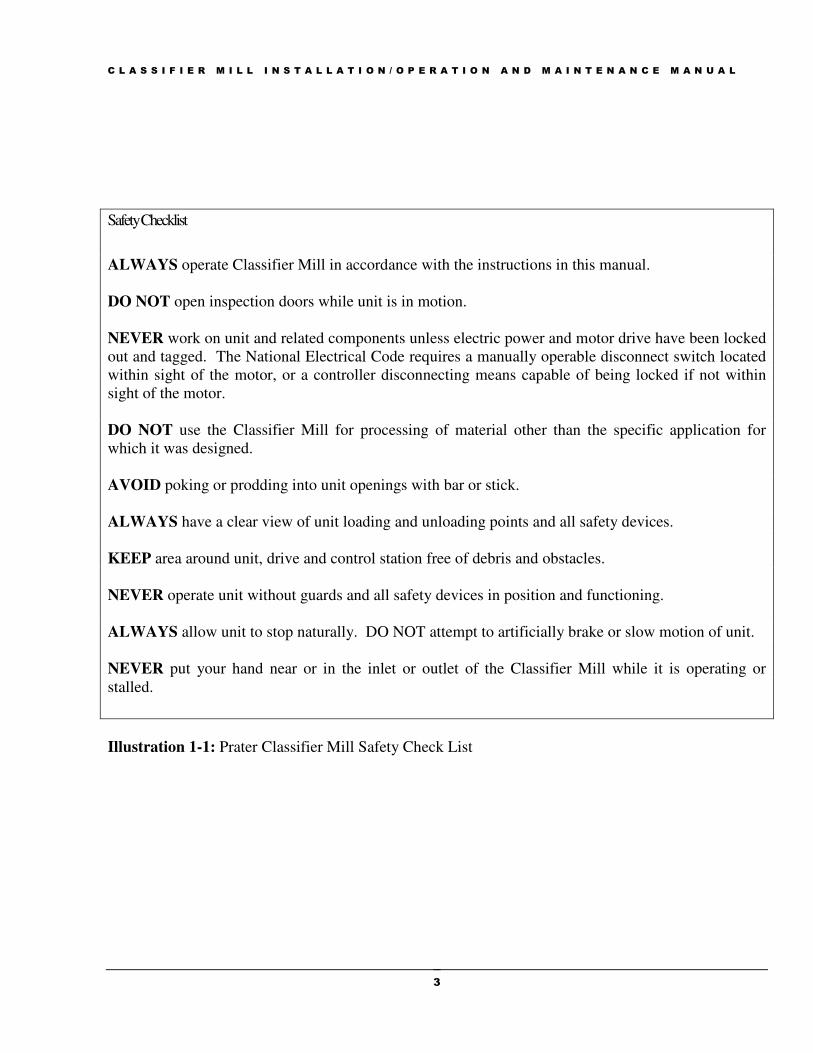
Illustration 1-1 is a checklist of safety precautions and proper operating procedures. Failure to observe
and follow the precautions may result in serious personal injury or property damage.
OPERATORS MUST BE INSTRUCTED NOT TO PUT HANDS, FINGERS OR OTHER FOREIGN OBJECTS IN THE MACHINE, AND NOT TO REMOVE ANY COVER, DOOR, HATCH OR OTHER PROTECTIVE DEVICES PLACED ON THIS MACHINE FOR THE SAFETY OF THE OPERATOR. ANY ATTEMPT TO DEFEAT THESE DEVICES COULD RESULT IN SERIOUS INJURY.
ELECTRICAL SERVICE TO THE MACHINE MUST BE LOCKED
OUT WHILE ANY REPAIRS OR ADJUSTMENTS ARE BEING MADE OR WHILE ANY COVER, DOOR, HATCH OR OTHER
PROTECTIVE DEVICE IS NOT IN PLACE.
WHEN PROCESSING MATERIALS THAT MAY REACT TO A SPARK
CAUSED BY METAL HITTING METAL OR STONES, ETC., THE USE OF
A MILL DUST COLLECTOR EQUIPPED WITH AN EXPLOSION VENT
IS STRONGLY RECOMMENDED. SEE APPENDIX G FOR MORE
INFORMATION ABOUT EXPLOSION VENTING.
C L A S S I F I E R M I L L I N S T A L L A T I O N / O P E R A T I O N A N D M A I N T E N A N C E M A N U A L
3
Safety Checklist
ALWAYS operate Classifier Mill in accordance with the instructions in this manual.
DO NOT open inspection doors while unit is in motion.
NEVER work on unit and related components unless electric power and motor drive have been locked
out and tagged. The National Electrical Code requires a manually operable disconnect switch located
within sight of the motor, or a controller disconnecting means capable of being locked if not within
sight of the motor.
DO NOT use the Classifier Mill for processing of material other than the specific application for
which it was designed.
AVOID poking or prodding into unit openings with bar or stick.
ALWAYS have a clear view of unit loading and unloading points and all safety devices.
KEEP area around unit, drive and control station free of debris and obstacles.
NEVER operate unit without guards and all safety devices in position and functioning.
ALWAYS allow unit to stop naturally. DO NOT attempt to artificially brake or slow motion of unit.
NEVER put your hand near or in the inlet or outlet of the Classifier Mill while it is operating or
stalled.
Illustration 1-1: Prater Classifier Mill Safety Check List

C L A S S I F I E R M I L L I N S T A L L A T I O N / O P E R A T I O N A N D M A I N T E N A N C E M A N U A L
4
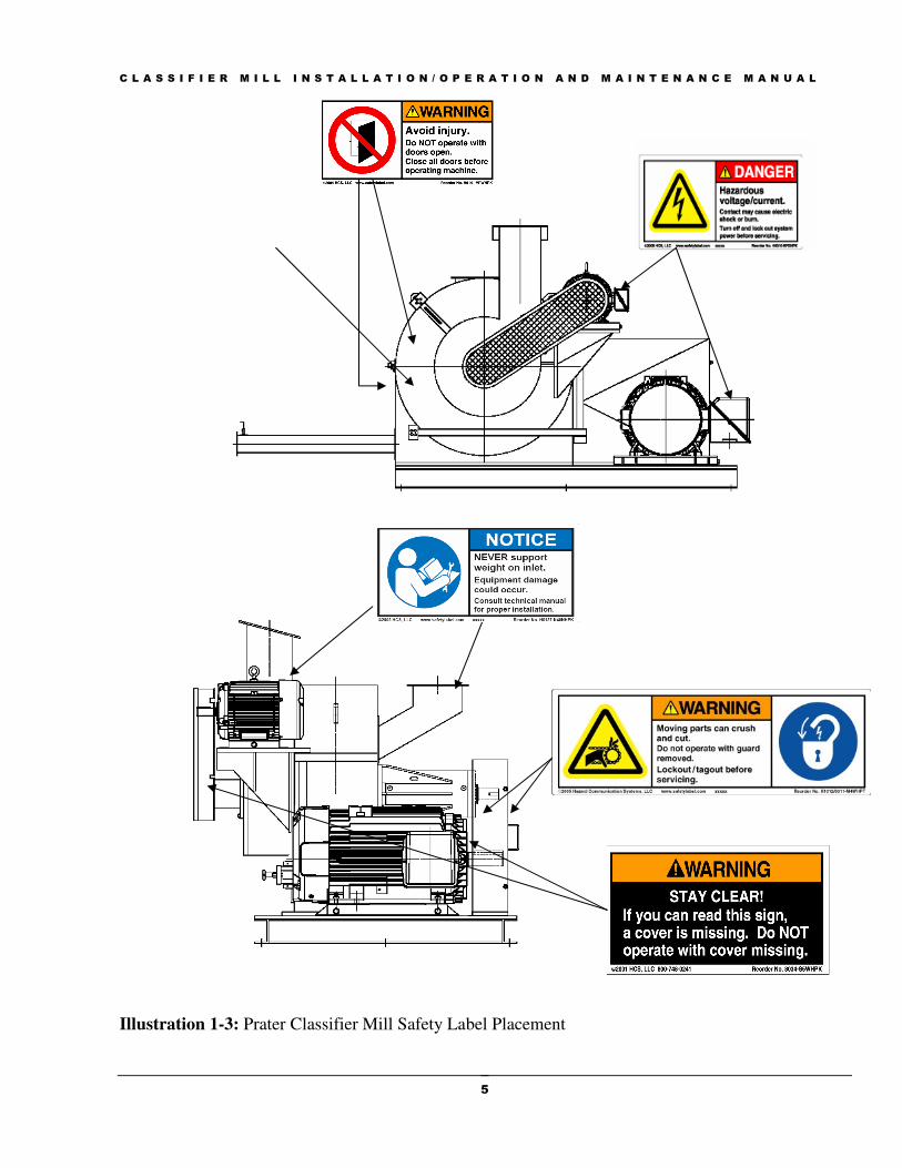
1.3 Classifier Mill Safety Labels
Illustration 1-2 shows the safety labels used on the Classifier Mill. These labels are important for
worker information and must not be removed from the unit.
Illustration 1-2: Prater Classifier Mill Safety Labels
C L A S S I F I E R M I L L I N S T A L L A T I O N / O P E R A T I O N A N D M A I N T E N A N C E M A N U A L
5
Illustration 1-3: Prater Classifier Mill Safety Label Placement
C L A S S I F I E R M I L L I N S T A L L A T I O N / O P E R A T I O N A N D M A I N T E N A N C E M A N U A L
6
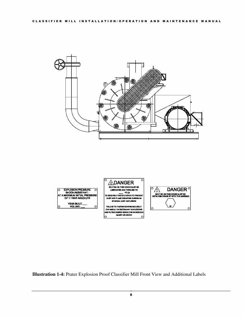
Illustration 1-4: Prater Explosion Proof Classifier Mill Front View and Additional Labels
C L A S S I F I E R M I L L I N S T A L L A T I O N / O P E R A T I O N A N D M A I N T E N A N C E M A N U A L
7
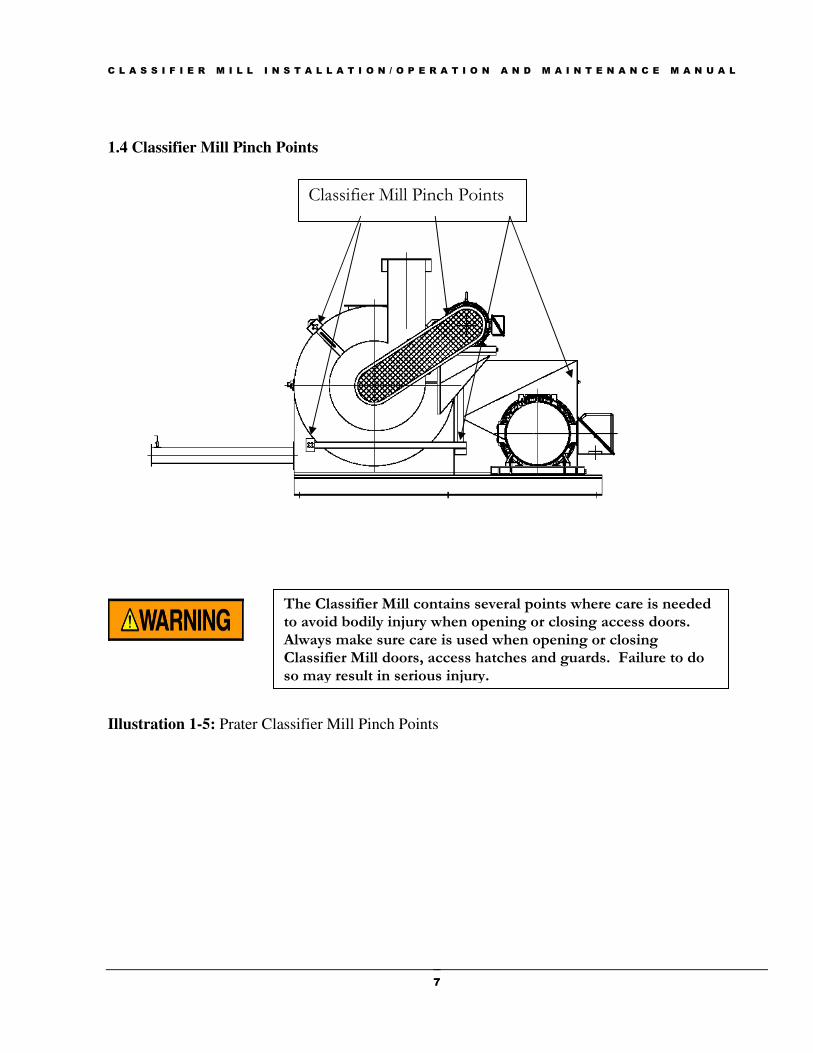
1.4 Classifier Mill Pinch Points
Illustration 1-5: Prater Classifier Mill Pinch Points
Classifier Mill Pinch Points
The Classifier Mill contains several points where care is needed to avoid bodily injury when opening or closing access doors. Always make sure care is used when opening or closing Classifier Mill doors, access hatches and guards. Failure to do so may result in serious injury.
C L A S S I F I E R M I L L I N S T A L L A T I O N / O P E R A T I O N A N D M A I N T E N A N C E M A N U A L
8
Section 2: Introduction
2.1 Manual Overview
This manual describes the installation requirements, procedures, and routine maintenance of Prater’s
Classifier Mill, Model #’s CLM – 36, CLM – 51, CLM – 76, and CLM - 101. Refer to this manual before
beginning and during installation. Keep this manual available for future reference. Cross section and
exploded views are located in the rear of the manual. The procedures throughout this manual refer to these
drawings. Locate the view for your Model Classifier Mill and refer to the view for clarification.
Reliable operation, personnel safety, and long service life of this equipment depend on three important
considerations:
� The care exercised during installation.
� The frequency/quality of maintenance and periodic inspections.
� A common sense approach to the Classifier Mills operation.
To keep operating costs down and profits up, carefully follow the instructions listed for installation,
operation, safety, and maintenance.
2.2 Receiving The Unit
When your shipment arrives, thoroughly inspect the Classifier Mill and all related equipment. In the
event of shipping damage, note the problem on the bill of lading or freight bill and make sure you
obtain the driver’s signature for a possible claim against the delivering carrier.
The Classifier Mill is always supplied with the mill pulley (Figure 6.5 - 19) and classifier pulley (if
applicable) mounted and the motor pulley and V-belts supplied loose (except when motor and base are
factory supplied).
The rotor’s are supplied loose and must be properly installed before operating the unit. Inspect the grinder
rotor and locate the serial number, which is stamped along with the letter F or FRONT on one side of the
rotor on the center hub or near the bore for the shaft. Rotor installation procedures are covered later in this
manual.
Section
2

C L A S S I F I E R M I L L I N S T A L L A T I O N / O P E R A T I O N A N D M A I N T E N A N C E M A N U A L
9
2.3 Before Installation
Be sure the installation crew or millwrights are aware of installation requirements. If they have any
questions or are unsure of proper procedures, clarify the matter to avoid improper installation. Section
3 of this manual covers important steps to ensure safe, vibration-free installation. Personnel
responsible for installation should be familiar with these procedures.
In preparing for installation, make sure you provide for all appropriate safety devices. Prater provides a
door interlock lock as standard on all classifier mills, unless specifically instructed by the customer, in
writing not to supply this device because the customer will use his own protective system. Prater Industries,
Inc. does not install your machine. It is your responsibility to provide lockout switches, guards, and other
safety devices and safety procedures to protect the machine operator or maintenance personnel.
2.4 Before Operation
Make sure operating personnel are well trained in procedures for operating and maintaining the
Classifier Mill. In particular, make sure they understand the essential safety precautions described in
Section 1 of this manual.
The RECEIVER is responsible for Inspection and filing claims against the CARRIER for any damage to the Classifier Mill in transit.
NOTICE
If the mill is to be installed in an enclosed room it is important to allow
adequate venting to provide proper air volume to the Classifier Mill.
Inadequate air volume will severely restrict throughput of the system
and may cause other problems.
NOTICE
IN SOME SITUATIONS, THE CLASSIFIER HOUSING (FIGURE 6.5 & 6.7 - 1) IS SHIPPED LOOSE FROM THE CLASSIFIER BASE (FIGURE 6.5 & 6.7 - 9). IN THESE SITUATIONS, DO NOT OPEN THE CLASSIFIER DOOR (FIGURE 6.5 & 6.7 - 6) BEFORE PROPERLY INSTALLING THE CLASSIFIER HOUSING ONTO THE BASE. THERE IS A POTENTIAL FOR THE UNIT TO TIP AND CAUSE PERSONAL INJURY OR DEATH AS WELL AS SEVERE DAMAGE TO THE UNIT.
C L A S S I F I E R M I L L I N S T A L L A T I O N / O P E R A T I O N A N D M A I N T E N A N C E M A N U A L
10
2.5 Classifier Mill Applications
The Prater Classifier Mill can be used for a wide range of applications in the field of fine and very fine
particle size reduction. Typical applications for the Prater Classifier Mill include processing chemicals,
pharmaceuticals, natural products, foodstuffs, cereal grains, powder coatings, organic and inorganic
pigments, and resins. Its design provides efficient utilization of applied horsepower.
2.6 Unit Design
.
Body assembly (Figure 6.5 & 6.7 - 1) is a rigid welded construction, with a bolted on bearing
assembly (Figure 6.5 & 6.7 - 2), which can be exchanged in one piece. The mill shaft runs on ball
bearings and carries the rotor assembly (Figure 6.5 & 6.7 - 3).
The rotor assembly is designed symmetrically. A single disc rotor (Figure 6.9 - 1) has wear resistant
blades (Figure 6.9 - 3) positioned in grooves. Retaining rings (Figure 6.9 - 2) hold the blades in the
grooves.
The screen assembly (Figure 6.5 & 6.7 - 4) is arranged around the rotor assembly, and is either bolted
to the back wall of the mill (CLM 36, 51) or is supported by pins threaded into the rear wall (CLM 76,
101). The rotor (Figure 6.5 & 6.7 - 3) and the screen assembly (Figure 6.5 & 6.7 - 4) are carefully
machined to maintain an accurate gap between the rotor assembly and the screen assembly to
maximize grinding efficiency. The classifier rotor (Figure 6.5 & 6.7 - 5) allows fine material to pass
and recirculates oversize material back to the grinding chamber for further reduction. By controlling
the speed of the classifier rotor, very precise control of the particle size is achieved. The large door
(Figure 6.5 & 6.7, 6) provides easy and sufficient access to all internal parts for inspection and
maintenance.
2.7 Operating Principle
Prater Classifier Mills operate on a high-speed impact principle. Material together with the necessary
amount of air is fed through the product inlet, either by gravity or within a conveying air stream, into the
rear of the Classifier Mill.
NOTICE
NOTICE
THIS PARAGRAPH REFERS TO FIGURES 6.4, 6.6 AND 6.8 IN THE
REAR OF THE MANUAL.
THIS PARAGRAPH REFERS TO FIGURE 6.16 IN THE REAR OF THE MANUAL.

C L A S S I F I E R M I L L I N S T A L L A T I O N / O P E R A T I O N A N D M A I N T E N A N C E M A N U A L
11
Prater highly recommends that the user install a magnet in the feed inlet to capture most ferrous
materials. Unless other arrangements have been made Prater does not normally supply this magnet. In
addition to the feed inlet magnet, for maximum production security, it is strongly recommended that
magnetic separation be incorporated into the system prior to the Classifier Mill as well. If other
foreign materials, such as stainless steel, aluminum, rock, etc may be contained in the product,
additional separation or screening should be used to maintain suitable screen and rotor life.
The rotor blades in the first stage grinding section act as a fan and generate an air stream through the
Classifier Mill. Particles move outward, impacting on each other, and then exit the first stage section
thru the screens or the center opening in the screenless assembly. After first stage grinding the ground
material is pulled toward the classifier rotor for classification. A secondary air stream is used to aid in
classification. Particles small enough to pass through the rotor are discharged with the air stream for
collection in the system dust collector. Oversize particles are rejected by the classifier and returned to
the second stage grinding section for further size reduction. Increasing or decreasing the classifier
speed can adjust the finished particle size.
The secondary air inlet allows air to be introduced between the primary grinding stage and the
classification zone. This ensures that a consistent airflow is maintained in the classification zone
irrespective of the air being generated by the grinding action. Because of this unique feature, feeds
that already contain significant quantities of in specification material can be fed into the secondary air
inlet. This allows removal of this material and lightens the load of the grinder to achieve higher
capacities or reduced energy consumption.
The classifier rotor is either direct motor driven (CLM 36, 51 with no bearing housing assembly) or
belt driven (CLM 76, 101 with bearing housing assembly). The speed of the classifier is VFD
controlled allowing instant changes to the speed and cut point of the classifier.
Due to the secondary airflow and the rotation of the classifier rotor, a spiraling air system is set up and
classification of the material is possible. As the particles approach the rotor, they are subjected to a
centrifugal force which can be several hundred gravities depending on the speed of the rotor.
On particles that are smaller than the cut point the centripetal drag force exerted on the particles by the
air stream overcomes this force and these particles are carried through the classifier rotor and exit the
mill with the air stream through the fines discharge. On particles that are larger than the cut point the
centrifugal force predominates. These particles are pushed away from the rotor and reenter the milling
chamber for second stage grinding.

C L A S S I F I E R M I L L I N S T A L L A T I O N / O P E R A T I O N A N D M A I N T E N A N C E M A N U A L
12
2.8 Classifier Mill Specifications
2.8.1 Dimensions
Table 2-1: Classifier Mill Dimensions
2.8.2:
Classifier Mill Speeds
Table 2-2: Classifier Mill Speeds
Classifier Mill CLM 36 CLM 51 CLM 76 CLM 101
Mill Rotor Diameter (In.) 13.8” 19.63" 29.63” 39.4”
Rotor Width (In.) 3.75” 5.3” 8.25” 11.0”
Mill Motor Size (HP) 20-40 30-60 75-125 125-250
Mill Motor (RPM) 3600 3600 1800 1800
Classifier Rotor Dia. (In.) 9.13” 11.8” 19.69” 27.11”
Classifier Rotor width (In.) 3.65” 5.48” 8” 10.34”
Class. Motor Size (HP) 3-5 5-7.5 10-15 15-25
Class. Motor RPM 3600 3600 1800 1800
~Weight (LBS) 552 1652 4100 8650
Min Air Volume (CFM) 750 1500 3000 6000
Max Air Volume (CFM) 1200 2400 4800 9600
Classifier Mill Grinder Rotor RPM
CLM-36 CLM-51 CLM-76 CLM-101
At 120 M/S 6538 4600 3045 2290
At 100 M/S 5450 3832 2540 1908
At 80 M/S 4360 3065 2031 1527
At 60 M/S 3270 2300 1523 1145
Class. Speed Range 400-6000 350-4600 325-3600 300-2250

C L A S S I F I E R M I L L I N S T A L L A T I O N / O P E R A T I O N A N D M A I N T E N A N C E M A N U A L
13
Section 3: Installation
3 . 1 Introduction
Proper installation of Prater’s Classifier Mill is critical for efficient and productive operation. The
proper site preparation and placement of the Classifier Mill and related equipment will insure that the
grinder operates safely and to its fullest capacity.
The following are important considerations in Classifier Mill installations:
3.1.1 Location
Make sure the operating location will provide strong, vibration-free base support and allow
easy access to all parts of the Classifier Mill. See Section 3.2 & 3.3.
3.1.2 Leveling The Classifier Mill must be mounted horizontally on a flat surface, which has sufficient
strength to prevent deflections of more than 0.003” and be large enough to incorporate the full
base of the Classifier Mill. Sections 2.3 and 2.4 explain how to check for proper leveling and
prevention of vibration damage during operation.
3.1.3 Drive
The Classifier Mill is always supplied with the mill pulley (Figure 6.5, 19) mounted and the
motor pulley (Figure 6.5, 17) and V-belts supplied loose (except when motor and base are
factory supplied). On the CLM-76/101 the classifier pulley and V-belt drive are supplied
mounted. Section 3.6 explains proper drive installation.
3.1.4 Grounding the Classifier Mill.
Effective July 1, 2007 all Classifier Mills will be shipped with grounding lugs installed to
easily make a connection from the mill base to earth ground. Failure to properly connect the
unit to earth ground can result in extensive damage to the mill bearings and rotor assemblies.
Refer to Appendix F for more information on static electricity and the importance of properly
grounding the unit.
3.2 Mill Base Foundation
Section
3

C L A S S I F I E R M I L L I N S T A L L A T I O N / O P E R A T I O N A N D M A I N T E N A N C E M A N U A L
14
The Classifier Mill must be supported in a vibration free location. The Classifier Mills CLM-36, and
CLM-51 are bolted down with four bolts. The Classifier Mill CLM-76 and CLM-101 are bolted down
with six bolts.
In most instances Prater Industries will supply the stand. If however the user desires to construct the
stand the stand need only be designed for a dead weight loading. The Classifier Mill is balanced to
very rigid specifications, eliminating any additional dynamic loading conditions.
The Classifier Mill must be mounted on a foundation that will not only support the weight of the mill
but will provide a vibration free environment as well. The recommended foundation sizes for each
model Classifier Mill can be found in Table 3-1 below.
TABLE 3-1 Classifier Foundation
In most cases mounting the mill to the floor will require some shimming of the mill base to
accommodate irregularities in the floor. After proper support and leveling of the Classifier Mill the
unit must be securely bolted to the floor. Prater recommends securing the mill with the fasteners in
Table 3-2.
TABLE 3-2 Recommended Fasteners
MODEL ANCHOR ANCHOR
DIAMETER LENGTH
CLM-36* 3/8” 6”
CLM-51 ½” 8”
CLM-76 ¾’ 10”
CLM-101 7/8” 12”
Prater Classifier Mill bases can be equipped with optional vibration dampeners (SHIPPED IN A
SEPARATE BOX), to minimize transmissions of high frequency noise and reduce vibration
transmission to the Classifier Mill from other surrounding equipment.
Model Mill Weight
(with largest motor)
(lbs)
Required
Foundation Mass
(lbs)
Foundation
Dimensions
Length x Width
(ft x ft)
Min. Depth of Concrete
(150 lb/ft^3 concrete)
(inches)
CLM-36 1,425 4,275 7-1/2 x 5-1/2 8-1/2
CLM-51 3,000 9,000 8-1/2 x 6-1/2 13
CLM-76 5,500 16,500 12 x 7-1/2 15
CLM-101 11,250 33,750 14-1/2 x 8-1/2 22
C L A S S I F I E R M I L L I N S T A L L A T I O N / O P E R A T I O N A N D M A I N T E N A N C E M A N U A L
15
*Note: The CLM 36 can be installed on a portable base with wheels, instead of a floor secured base.
3.3 Clearance
There should be sufficient open space in all directions around the Classifier Mill to allow access for
changing screens and other maintenance operations. No excessive weight can be resting on or
supported from the Classifier Mill.
3.4 Installing the Classifier Mill Rotors
Depending on the size of the unit power/mechanical assistance installing the rotor may be necessary.
Prater Industries manufactures many assistive tools designed specifically for rotor installation and
removal. Contact Customer Service for details and pricing information. These instructions refer
to Figures in Section 6 in the rear of the manual.
3.4.1 Grinding Rotor Installation
1. For the CLM 36, and CLM 51 remove the entire screen frame assembly (Figure 6.5, 4) by
removing the hex head cap screws securing the frame to the rear of the mill housing.
2. For the CLM 76, and CLM 101 remove the baffle plate (Figure 6.11, 3) to allow clearance for
the rotor.
3. Locate the serial number and the F or Front, which should be stamped on the rotor and face the
door after installation (Figure 6.9).
4. Slide rotor (Figure: 6.5 & 6.7, 3) onto shaft assembly (Figure 6.5 & 6.7, 2).
Classifier Mill Rotors contain sharp edges, which may cause personal injury if not handled properly. Always use care when working with Classifier Mill Rotors. Classifier Mill Rotors can be very heavy. Always insure that proper methods and adequate support are used at all times.
Rolling the Classifier Mill Rotor on the rotor blades may seriously
damage the rotor. CAUTION
NEVER BLOCK THE ROTOR USING THE ROTOR BLADES TO
PREVENT ROTATION DURING TIGHTENING OF THE BOLTS. CAUTION

C L A S S I F I E R M I L L I N S T A L L A T I O N / O P E R A T I O N A N D M A I N T E N A N C E M A N U A L
16
5. Align key ways and insert key.
6. The rotor and key should slide smoothly and seat against the shaft shoulder.
7. Install end cap, lock washer, and bolt (Figure 6.1 - 9, 19, 20) and using Table 3-1, tighten to the
recommended torque.
8. Re-install screen frame assembly or baffle plate.
3.4.2 Classifier Rotor Installation
1. For the CLM-36: Insert the rotor spacer and key (Figure 6.10 - 11, 14) into the hub assembly
(Figure 6.10 - 1). Align the keyways and insert the classifier rotor onto the motor shaft (Figure
6.4 - 5, 10). Install washer and bolt (Figure 6.10 - 12,13) and tighten to recommended torque.
2. For the CLM-51/76/101: Locate the keyway on the shaft and rotate to the 12 o’clock position
and insert the key (Figure 6.4 - 18). With the keyway at the 12 o’clock position slide the
classifier rotor onto the shaft. It may be necessary to rotate slightly to align the keyways. insert
end cap, cap screw and washer (Figure 6.11 - 3, 14, 20) into recess of classifier rotor and tighten
to recommended torque listed in Table 3-1.
Table 3-1: Recommended bolt torque
3.5 Vibration
The Prater Classifier Mill is constructed to run without noticeable vibration. Vibration indicates a problem
that must be found and corrected immediately. If left uncorrected, vibration will cause: Classifier Mill
damage, Structural damage. There are several conditions that cause vibration, including:
• Uneven base (See Section 3.2)
• Loose motor fasteners
• Defective motor or Classifier Mill bearings (See Section 5)
• Other equipment transferring vibration thru contact with the Classifier Mill.
• Worn, missing or broken rotor blades (Figure 6.9 - 3)
• Material buildup on rotor disk or blades.
3.6 Drive
The Classifier Mill has been supplied with the proper size pulley, balanced and properly mounted. In
case it’s necessary to change the speed, always change only the pulley on mill shaft (Figure 6.7 - 20).
Mill Mill Bolt Size Class. Bolt Size Torque (in -lb)
CLM 36 3/8” - 16 Grade 8 525
CLM 51 5/8” - 11 Grade 8 2550
CLM 76 ¾” - 10 Grade 8 4500
CLM 101 7/8”- 9 Grade 8 7275

C L A S S I F I E R M I L L I N S T A L L A T I O N / O P E R A T I O N A N D M A I N T E N A N C E M A N U A L
17
A maximum tip or circumferential speed however, of 120 meters per second (23, 616 FPM) should
never be exceeded. The motor pulley is also standard, and is properly balanced and sized to provide
the proper tip speed.
Alignment of pulleys after motor installation is very important because of the high rotational speeds.
Improper alignment causes rapid bearing failure on motor and/or Classifier Mill (Illustration 3-2).
Proper belt tensioning is very important. The belts are a matched set and require sufficient tension to
prevent slippage under full motor load. New units are shipped with the pulleys laser aligned with a
preset centerline distance to insure proper tensioning. The belts should be inspected frequently during
the first few days of operation and then periodically thereafter. The new belts have a tendency to
stretch, causing them to loosen up and squeal. (See any standard belt manufacturer’s catalogue for
tensioning specifications).
A V-belt guard will be provided with all Classifier Mills, unless the customer requests, in writing, that
the guard need not be provided. The guard is built to rigid specifications to our standard center
distances and locations. “OSHA” requirements mandate guarding all drives; therefore the customer
MUST supply an approved design guard if they request Prater Companies not to supply one.
Exposed V-belts are a HAZARDOUS condition.
Illustration 3-2 Pulley Alignment
3.7 Bearing Assembly Air Purge
Units shipped after December 31, 2001 will incorporate a front bearing cover/air purge assembly as an
integral part of the mill bearing assembly. Prater Industries, Inc. strongly recommends that
INCORRECT CORRECT

C L A S S I F I E R M I L L I N S T A L L A T I O N / O P E R A T I O N A N D M A I N T E N A N C E M A N U A L
18
customers utilize the air purge. The purge is installed to protect the mill bearings from product
contamination due to dusty conditions and water during any cleaning of the mill and support
equipment. To be effective the air purge must operate at all times. As received the mill bearing
assembly incorporates a 1/8” NPT tapped hole, which is plugged at the factory. This port is located in
the front bearing cover, which incorporates a lantern ring or an air assisted Inpro seal to operate the air
purge assembly. The air supply to the purge must be clean dry compressed air at 2 – 4 psi. The air
volume requirements will be 4 – 10 ACFM depending on the size of the mill.
3.8 Feeding
After the Classifier Mill is mounted in place, the product inlet (Figure 6.7 - 8) must be connected to a
device capable of providing a uniform controlled feed rate to the mill. Prater Industries, Inc.
recommends that feeding devices be operated with a Variable Frequency Drive to allow for
adjustments due to changes in the feed material characteristics.
IT IS ESSENTIAL THAT THE FEED BE CONTROLLED in order to prevent overfeed, or uncontrolled
pulsations which can overload the Classifier Mill. Any device, such as a slide gate, rotary feeder, vibrating
trap feeder, screw conveyor, etc., may be used, as long as it provides a uniform controlled feed. The feeding
device should be supported from the building or other static structure. DO NOT support the feeder on the
mill feed inlet (Figure 6.7 - 8).
Establishing feed rate by averaging total feed over a period of time may allow non-uniform feed. There are
no guarantees that short feeding cycles may not be too high or provide erratic feed during the run.
3.8.1 Protecting the Mill from Tramp Material Damage
The Prater Classifier Mill must be protected from damage by tramp material. One way to provide
this protection is to provide an in-line magnet in the incoming product stream immediately before the
Mill inlet. It is the user’s responsibility to provide this protection. Damage caused to the Mill because
it lacks such protection will not be covered by the Prater warranty.
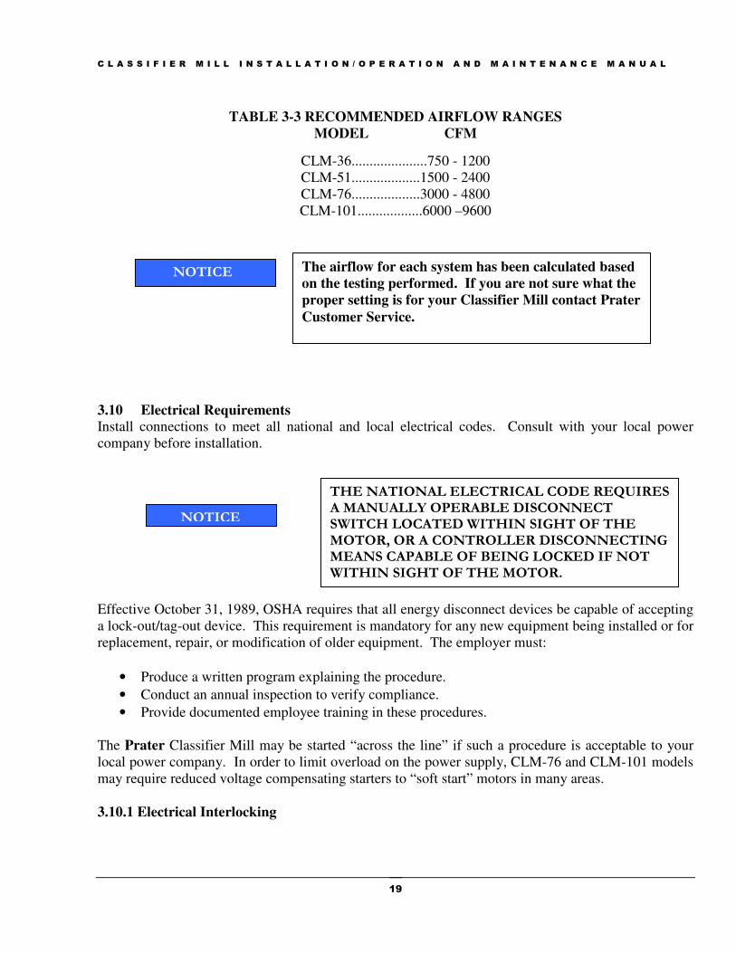
3.9 Required Air Flow
Table 3-3 lists the Classifier Mill models matched with the required airflow volumes in cubic feet per
minute.
The capacity and/or fineness listed will only be achieved if the density, particle size, shape, moisture content, and chemical make up of the feed material is consistent and IDENTICAL to that which we tested or specified, and is fed evenly and uniformly in a controlled manner to the PRATER unit(s) shown.
NOTICE
C L A S S I F I E R M I L L I N S T A L L A T I O N / O P E R A T I O N A N D M A I N T E N A N C E M A N U A L
19
TABLE 3-3 RECOMMENDED AIRFLOW RANGES
MODEL CFM
CLM-36.....................750 - 1200
CLM-51...................1500 - 2400
CLM-76...................3000 - 4800
CLM-101..................6000 –9600
3.10 Electrical Requirements
Install connections to meet all national and local electrical codes. Consult with your local power
company before installation.
Effective October 31, 1989, OSHA requires that all energy disconnect devices be capable of accepting
a lock-out/tag-out device. This requirement is mandatory for any new equipment being installed or for
replacement, repair, or modification of older equipment. The employer must:
• Produce a written program explaining the procedure.
• Conduct an annual inspection to verify compliance.
• Provide documented employee training in these procedures.
The Prater Classifier Mill may be started “across the line” if such a procedure is acceptable to your
local power company. In order to limit overload on the power supply, CLM-76 and CLM-101 models
may require reduced voltage compensating starters to “soft start” motors in many areas.
3.10.1 Electrical Interlocking
THE NATIONAL ELECTRICAL CODE REQUIRES A MANUALLY OPERABLE DISCONNECT SWITCH LOCATED WITHIN SIGHT OF THE MOTOR, OR A CONTROLLER DISCONNECTING MEANS CAPABLE OF BEING LOCKED IF NOT WITHIN SIGHT OF THE MOTOR.
NOTICE
The airflow for each system has been calculated based
on the testing performed. If you are not sure what the
proper setting is for your Classifier Mill contact Prater
Customer Service.
NOTICE

C L A S S I F I E R M I L L I N S T A L L A T I O N / O P E R A T I O N A N D M A I N T E N A N C E M A N U A L
20
As a general guide, the last piece of process equipment is started first with subsequent starts working
up the line to the feeder, which is the last item started.
3.11 Unit Check
After installation is complete, carefully inspect all work before the installation crew leaves to see that
all instructions have been properly followed.
3.12 Adjustments
To achieve the most efficient performance with the Classifier Mill through all possible adjustments it
is important to remember how particle size reduction is achieved through impact and acceleration.
The following adjustments will influence the grinding results.
3.12.1 SPEED - Changing the pulley on the mill shaft.
Larger: slows tip speed – coarser product.
Smaller: raises tip speed – fine product.
3.12.2 CLASSIFIER SPEED – Changing the frequency of the classifier VFD ouput
Higher Frequency: Increases classifier speed and produces a finer product.
Lower Frequency: Decreases classifier speed and produces a coarser product.
3.12.3 SCREEN - Different screen hole sizes give different particle sizing.
Larger holes – coarser product.
Smaller holes – finer product.
3.12.4 JAWS - Adds to impact – finer product
A TIME DELAY IS ALWAYS REQUIRED BETWEEN START-UP OF THE CLASSIFIER MILL AND START UP OF THE FEEDER, TO ALLOW THE CLASSIFIER MILL TO REACH FULL OPERATING SPEED BEFORE PRODUCT IS INTRODUCED.
NOTICE
ON SHUT DOWN, A TIME DELAY IS REQUIRED TO ASSURE THAT ALL OF THE PRODUCT HAS CLEARED THE CLASSIFIER MILL.
NOTICE
C L A S S I F I E R M I L L I N S T A L L A T I O N / O P E R A T I O N A N D M A I N T E N A N C E M A N U A L
21
3.12.5 AIRFLOW – Higher - airflow leads generally to coarser grind and higher capacity.
Lower - airflow usually gives finer grind and lower capacity.
3.12.6 FEED – In some cases a finer pregrind will increase capacity.
Uniform feed – smooth, uniform amperage draw, efficient operation, high capacity
Non-uniform feed – pulsating amperage draw, inefficient operation, low capacity
The more non-uniform the feed rate the greater the amperage pulsating and the higher the reduction in
capacity. In the case of rotary valve type feeders Prater requires a minimum of 15 RPM to insure a
uniform feed. Speeds less than 15 RPM will result in larger amperage pulsations, inconsistent finished
product particle distribution and inefficient electrical use.
C L A S S I F I E R M I L L I N S T A L L A T I O N / O P E R A T I O N A N D M A I N T E N A N C E M A N U A L
22
Section 4: Operation
4.1 Introduction
Pre-run inspections and safety checks throughout this section insure that the Classifier Mill is in proper
operating condition. Other aspects of operation covered in this section include: start-up and shut
down sequences.
4.2 Pre-Run Inspection
Before attempting to run the Classifier Mill even to check rotation, perform the following inspection:
1. Open access door (Figure 6.5 & 6.7 - 6).
2. For the CLM 36 remove the screen frame assembly ( Figure 6.5 - 4), for CLM 51, 76, and 101
remove the baffle plate (Figure 6.13 & 6-14 - 1). Remove any loose material or foreign matter
lying in the Classifier Mill.
3. Reinstall the screen assembly, or baffle plate.
3. Turn the rotor assembly by hand to see that it turns freely.
4. Close and lock door.
5. Inspect the mill drive for proper sheave alignment and belt tensioning
4.3 Safety Check-Up
Before starting the Classifier Mill check the following:
� The inside of the Classifier Mill for foreign material, i.e., nuts, bolts, wire.
� That screen assembly is properly installed.
� That the rotor assembly moves freely and is not hitting surrounding parts.
� That all guards are mounted and secure.
� That all inspection doors are closed and locked.
Section
4
ELECTRICAL SERVICE TO THE MACHINE MUST BE
LOCKED OUT WHILE ANY REPAIRS OR ADJUSTMENTS ARE BEING MADE OR WHILE ANY COVER, DOOR, HATCH OR
OTHER PROTECTIVE DEVICE IS NOT IN PLACE.
C L A S S I F I E R M I L L I N S T A L L A T I O N / O P E R A T I O N A N D M A I N T E N A N C E M A N U A L
23
� That all electrical starting equipment, meters, disconnect switches, and other control devices
are clearly visible readily accessible to the operator.
4.4 Rotor Rotation
The rotors in the classifier mill both rotate counter clockwise when visualized by looking at the door
of the classifier mill.
4.5 Start-Up Sequence
This start-up sequence is intended as a general guide. The start-up sequence you use will depend on
your specific operation and any unique characteristics of your installation.
As a general guide to electrical interlocking, you turn on equipment in reverse order from product
flow. The final piece of equipment to be started should be the product feeder.
4.6 Running the Classifier Mill For The First Time
Insure that all equipment has been “bumped” to insure proper rotation
If the system is being controlled by a PLC, discuss the start and shut down sequence with the
programmer. In a standard Classifier Mill installation the sequence is as follows:
CLASSIFIER MILL GRINDING SYSTEMS CAN
GENERATE NOISE LEVELS THAT MAY SEVERELY
DAMAGE HEARING. IF THE CLASSIFIER MILL IS
OPERATING IN AN ENCLOSED AREA EAR
PROTECTION MUST BE WORN AT ALL TIMES WHEN
THE SYSTEM IS RUNNING. PRATER INDUSTRIES CAN
PROVIDE MUFFLING DEVICES TO REDUCE THIS NOISE
UPON REQUEST.
A TIME DELAY IS ALWAYS REQUIRED BETWEEN
START-UP OF THE CLASSIFIER MILL AND START UP
OF THE FEEDER, TO ALLOW CLASSIFIER MILL TO
REACH FULL OPERATING SPEED BEFORE PRODUCT
IS INTRODUCED. ON SHUT DOWN, A TIME DELAY IS
REQUIRED TO ASSURE THAT ALL OF THE PRODUCT
HAS CLEARED THE CLASSIFIER MILL
NOTICE

C L A S S I F I E R M I L L I N S T A L L A T I O N / O P E R A T I O N A N D M A I N T E N A N C E M A N U A L
24
1. Start the system chiller, dryer, etc. if installed.
2. Start the finished product, discharge equipment and any post milling equipment, i.e. sifters, mixers,
etc.
3. Start the system fan, pulse and the classifier motor.
4. Start the mill.
5. The first time the mill is started perform the following:
A. Feel the bearing assembly to determine if there is any excessive vibration.
B. By feel, determine if any vibration exists between the bearing housing front plate and the mill
rear wall.
C. Check the mill floor mounts by feel to determine if there is any vibration between the mill
footpads and the floor mount.
D. If the vibration feels excessive and correcting items B-D does not alleviate the problem follow
this procedure:
A. If the grinder rotor was unmarked reverse the rotor and repeat item 3a above.
B. If the rotor is marked and properly installed, recheck the rotor for loose blades.
C. Next tighten all the fasteners for the mill housing, motor, motor base, bearing housing,
and feed inlet.
D. Restart the mill and keep it running until bearing temperature is stable / falling or the
unit reaches 200 degrees F.
E. If the bearing housing temperature reaches 200 degrees F stop the unit and call Prater
for consultation.
6. If the vibration initially feels normal, then while the bearing temperature rise is being monitored
set the system dampers and perform the system airflow readings.
7. The normal arrangement for the dampers should be an approximate 40/60 split between the feed
inlet and the secondary air inlet. If readings are not available to make the split the Operator should
set the dampers by feel.
8. Start the feed to the mill at about 50 percent of the rated capacity or 60 percent of the motor full
load amps. Continue running at this setting until the system stabilizes. Stabilization occurs when
the fluctuation in the mill motor current draw is between 5 and 10 percent of the FLA rating of the
motor. This value is determined by voltage, hp and operator experience. There should only be
light loading of the classifier motor at this point.
9. If stabilization does not occur at this setting it may still be possible to achieve stabilization at a
higher feed rate. After a sample has been collected, analyzed, and any necessary changes to the
mill have been completed the feed rate should be increased in increments.
10. Once the maximum sustainable feed rate has been achieved a sample should be collected for
analysis. At this time a means of determining the feed rate should be found. Acceptable methods
for attaining this are:
a. Direct timing from the feed mechanism.
b. Direct timing from the discharge of a cyclone.
c. Shift timing in an operation where the mill is being continuously fed over a shift of at
least eight hours.
Unacceptable methods for attaining this are:

C L A S S I F I E R M I L L I N S T A L L A T I O N / O P E R A T I O N A N D M A I N T E N A N C E M A N U A L
25
a. Direct timing from the discharge of a new uncoated dust collector or one where the filters
have recently been changed.
b. Shift timing in an operation where the feed is anything other than continuous.
4.7 Initial inspection after 2 days or 48 hours running time
After not more than 48 hours of operation the customer should open the mill up and inspect
the mill internals.
� Inspect the rotor for any blade loosening and retighten as needed.
� Inspect all the internal parts for any wear or material buildup.
� Inspect the parts for impact damage from foreign material.
While inspecting the blades and securing the fasteners it is important to check each
individual blade to insure there are no loose ones before the rotor is installed. After each
eight hours of running the blades should be checked and retightened to see if any loose
blades are identified. These checks should continue until two consecutive inspections
reveal no loose blades.
The customer should inspect the mill monthly for materials that tend to be abrasive. For
softer items, i.e. sugar the inspection interval should be quarterly. The customer should use
these inspections to determine the life of the internal components and implement a
Preventive Maintenance Program to insure continuous operation.
DO NOT OPEN THE CLASSIFIER MILL OR ATTEMPT
ANY FORM OF INSPECTION UNTIL BOTH ROTORS
HAVE COME TO A COMPLETE STOP AND THE
ELECTRICAL DISCONNECT HAS BEEN LOCKED IN THE
OPEN POSITION.

C L A S S I F I E R M I L L I N S T A L L A T I O N / O P E R A T I O N A N D M A I N T E N A N C E M A N U A L
26
Section 5: Maintenance
5.1 Introduction
The Classifier Mill is designed to operate with minimal maintenance. Routine inspections and regular
maintenance will identify any worn or broken parts before they become a problem. Worn or broken parts
are damaging to the Classifier Mill and its output. When operated without vibration or foreign materials
entering the screen assembly, only those parts subject to the heaviest wear, i.e. drive belts, rotor blades, and
screens will require maintenance.
5.2 Routine Inspection
High speed rotating equipment requires regular routine preventative maintenance procedures.
Regular inspection of the rotor blades (Figure 6.9 - 3) should be carried out particularly where abrasive
materials are being processed. The wear pattern on the rotor blades (Figure 6.9 - 3) will vary
depending upon operating conditions. Visual inspection will show the necessity for change.
Prater Classifier Mill blades are manufactured from a special alloy steel designed to give them
strength and durability. The blades are inspected for cracks or defects prior to being installed at the
factory or shipped as replacement parts. The service life of the blades is dependent on several factors
such as: abrasiveness of material being ground in the mill; contact with foreign material in the feed
(i.e. metal, stones, etc.); excessive vibration over a period of time, foreign material entering the mill,
and unintentional damage prior to being installed in the rotor such as being dropped on the floor or
miss-handled during shipping.
To help prevent the problems mentioned above, Prater recommends the following:
1. Install components in the process before the mill to remove foreign material
and break-up or remove large product agglomerations.
Section
5
DO NOT OPEN THE CLASSIFIER MILL OR ATTEMPT
ANY FORM OF INSPECTION UNTIL THE CLASSIFIER
MILL HAS COME TO A COMPLETE STOP AND THE
ELECTRICAL DISCONNECT HAS BEEN LOCKED IN THE
OPEN POSITION.

C L A S S I F I E R M I L L I N S T A L L A T I O N / O P E R A T I O N A N D M A I N T E N A N C E M A N U A L
27
2. Prater recommends inspecting the blades every 30 days for wear or damage.
3. When inspection indicates that damage has occurred (bending, gouging, pitting, discoloration,
etc.), replace all blades in the mill with new ones. The old undamaged blades can be magnetic
particle tested, and possibly reused.
4. Install vibration detection equipment to help detect a problem before a blade breaks.
5. Instruct maintenance personnel in regard to proper handling of the blades
during installation.
The blade-retaining ring (Figure 6.9 - 2) should be inspected for sign of wear and replaced if necessary
and the screens (Figure 6.12, 6.13, 6.14 - 4) should not be allowed to wear so thin as to break up.
The rotors (Figures 6.5 & 6.7 - 3, 5) are statically and dynamically balanced to a high standard to
ensure smooth, vibration-free running. Should increased vibration develop, immediately stop the
machine.
5.3 Screens
The screens (Figure 6.12, 6.13, 6.14 - 4) help control the particle size of the final product. Inspect the
screens frequently to maintain the desired output and clean as necessary. The screens may require
replacement if they are showing signs of wear.
5.3.1 Screen Replacement
5.3.2 CLM-36 and CLM-51 Screen Replacement
1. Turn off the Classifier Mill and allow the rotors (Figures 6.5 - 3, 5) to come to a complete stop.
2. Lock out electrical power to the Classifier Mill.
3. Open door (Figure 6.5 - 6) and remove the screen frame assembly (Figure 6.5 - 4) by
removing bolts (Figure 6.12 - 7) from the back of the mill housing.
4. Remove Socket Head Cap Screws (Figure 6.12 - 8) this will allow removal of the baffle plate
and the grinding ring.
5. Remove screens (Figure 6.12 - 4).
6. Clean all slots in housing, rear ring, front grinding ring, and grinding jaws.
7. Slide new screens into position, making certain that they are flush with the groove in the rear
ring.
DO NOT OPEN THE CLASSIFIER MILL OR ATTEMPT
ANY FORM OF INSPECTION UNTIL BOTH ROTORS
HAVE COME TO A COMPLETE STOP AND THE
ELECTRICAL DISCONNECT HAS BEEN LOCKED IN THE
OPEN POSITION.

C L A S S I F I E R M I L L I N S T A L L A T I O N / O P E R A T I O N A N D M A I N T E N A N C E M A N U A L
28
8. To replace grinding jaw (Figure 6.12 - 3), remove flat head screws (Figure 6.12 - 8) and install
new grinding jaws as needed.
9. Replace full grinding ring and baffle plate, and secure with screws removed in step 4.
10. Reinstall screen frame assembly and secure with bolts removed in step 3.
11. Rotate the mill rotor by hand to check for any interference between the rotor and grinding jaws.
12. Close door and secure
5.3.3 CLM-76 and CLM-101 Screen Replacement
1. Turn off the Classifier Mill and allow the rotors (Figure 6.7 - 3,5) to come to a complete stop.
2. Lock out electrical power to the Classifier Mill.
3. Open door (Figure 6.7 - 6).
4. Remove bolt and lock washer (Figure 6.14 - 7) and remove baffle plate (Figure 6.14 - 1).
5. Remove front grinding ring (Figure 6.14 - 2) by sliding the segmented parts off of the support
pins.
6. Slide out screens (Figure 6.14 - 4)
7. Clean all slots in the full grinding ring, segments, rear ring, and the housing.
8. At this point you can also replace the rear grinding jaws by sliding them off the support pins
and replacing as necessary.
9. Slide new screens into position, making certain that they are flush with the housing groove.
10. Replace grinding ring segments removed in step 5.
11. Replace baffle plate removed in step 3.
12. Rotate the mill rotor by hand to check for any interference between the rotor and grinding
jaws.
13. Close door and secure.
5.3.4 Replacing the Screenless Frame Rings
1. Turn off the Classifier Mill and allow the rotors (Figure 6.5 & 6.7 - 3,5) to come to a complete
stop.
2. Lock out electrical power to the Classifier Mill and open the door.
3. Remove lockwasher and nut assembly (Figure 6.15 - 1) and remove the baffle plate (Figure
6.15 - 2).
4. Remove the front grinding ring (Figure 6.15 - 3) by sliding it forward off the guide pins
(Figure 6.15 - 6)
5. Remove the spacers (Figure 6.15 - 4) from the guide pins.
6. Slide the rear-grinding ring (Figure 6.15 - 5) off the guide pins.
NOTICE If you are replacing the guide pins (Figure 6.14 - 6), the pins
in the CLM 36, and CLM 51 are removed from the back of the
mill housing. For the CLM 76, and CLM 101 the pins are
removed from the door side of the housing, and don’t
incorporate a lockwasher.
C L A S S I F I E R M I L L I N S T A L L A T I O N / O P E R A T I O N A N D M A I N T E N A N C E M A N U A L
29
7. Slide the new rear-grinding ring onto the new or thoroughly cleaned old guide pins.
8. Install spacers removed in step 6.
9. Slide the new front grinding ring onto the guide pins.
10. Reinstall the baffle plate and secure with lockwasher and nut assembly removed in step 4.
11. Close door and secure.
5.4 Mill Grinder Rotor Blade Replacement
1. Turn off the Classifier Mill and allow the rotors (Figure 6.5 & 6.7 - 3,5) to come to a complete
stop.
2. Lock out electrical power to the Classifier Mill.
3. Open door (Figure 6.5 & 6.7 - 6).
4. For the CLM 36 and CLM 51 follow the procedure in section 5.3.2 to remove the entire screen
frame assembly.
5. For the CLM 76, and CLM 101 remove bolt and lock washer (Figure 6.14 - 7) and remove
baffle plate (Figure 6.14 - 1).
6. Remove fasteners (Figure 6.9 - 5) that secure the retaining ring (Figure 6.9 - 2).
7. Mark the position of the retaining ring to ensure it is reinstalled in the same position. Use the
tapped holes in the retaining ring to unseat the ring.
8. Remove the worn/broken blades.
DO NOT OPEN THE CLASSIFIER MILL OR ATTEMPT ANY FORM OF INSPECTION UNTIL THE CLASSIFIER MILL HAS COME TO A COMPLETE STOP AND THE ELECTRICAL DISCONNECT HAS BEEN LOCKED IN THE OPEN POSITION.
THE ROTOR (Figure 6.5 & 6.7 - 3) DOES NOT HAVE TO BE
REMOVED FROM MILL BEARING HOUSING SHAFT
(FIGURE 6.5 & 6.7 - 2), HOWEVER PRATER INDUSTRIES,
INC. RECOMMENDS REMOVAL OF THE ROTOR TO
INSURE THAT BOTH RETAINING RINGS ARE PROPERLY
TIGHTENED.
NOTICE
WHEN REPLACING DAMAGED OR WORN BLADES WITH
NEW BLADES, IT IS NECESSARY TO ALSO REPLACE THE
BLADE DIRECTLY OPPOSITE THE WORN BLADE. IF THE
BLADES ARE PROPERLY MATCHED THIS SHOULD KEEP
THE ROTOR IN BALANCE.
NOTICE
C L A S S I F I E R M I L L I N S T A L L A T I O N / O P E R A T I O N A N D M A I N T E N A N C E M A N U A L
30
Proper installation of the rotor blades is critical to insure continued vibration free operation and
unnecessary downtime due to excessive vibration. Rotor blades purchased from Prater Industries, Inc.
are shipped as a matched set. A matched set of blades is a set of blades where the deviation between
the heaviest and lightest blades are within Prater tolerances, and does not mean the blades are all the
same weight. Prater Industries, Inc. recommends that customers weigh the individual blades to insure
uniform weight distribution around the rotor.
9. If the full set of blades is to be replaced refer to Appendix H.
10. Install the new blades.
11. Position the retaining ring and align with the markings from step 7.
12. Install the fasteners removed in step 6.
13. Check each blade to make sure there is no movement in any direction.
14. Reinstall the baffle plate or screen frame.
15. Close and secure the door.
After each eight hours of running the blades should be checked and retightened to see if any loose
blades are identified. These checks should continue until two consecutive inspections reveal no loose
blades.
IF ONE BLADE IS CRACKED, IT IS RECOMMENDED THAT ALL BLADES BE MAGNETIC PARTICLE TESTED TO DETECT ANY UNSEEN HAIRLINE CRACKS. BLADES WITH THESE IMPERFECTIONS WILL PROBABLY BREAK AND CAUSE ADDITIONAL BLADE FAILURES AND OTHER EQUIPMENT DAMAGE. USED BLADES, WHICH SHOW NO CRACKS OR IMPERFECTIONS AFTER MAGNETIC PARTICLE TESTING ARE NORMALLY SAFE TO REINSTALL. IF IN DOUBT OR IF YOU HAVE ANY QUESTIONS CONTACT PRATER INDUSTRIES FOR HELP AND/OR RETURN OF THE ROTOR FOR FURTHER INSPECTION AND TESTING.
CAUTION
CAUTION IT IS IMPORTANT TO STAGGER THE BOLTS ON EITHER SIDE OF THE ROTOR WHEN REINSTALLING THE RETAINING RINGS (FIGURE 6.9 - 2) TO ENSURE PROPER TIGHTENING OF ROTOR BLADES. NEVER USE THE SAME HOLE FOR TWO BOLTS!
C L A S S I F I E R M I L L I N S T A L L A T I O N / O P E R A T I O N A N D M A I N T E N A N C E M A N U A L
31
5.5 Classifier Top Fan Blade Replacement
The purpose of the classifier top fan blades is to prevent coarse material from passing over the top
of the classifier rotor and discharging into the fines collector. When these blades begin to wear
excessively the classifier speed must be increased to keep product in specification. This results in
heavier loading of the grinder and reduced capacity. Rounding of the outside corner of the top fan
blades indicates worn blades.
1. Turn off the Classifier Mill and allow the rotors (Figure 6.5 & 6.7 - 3,5) to come to a complete
stop.
2. Lock out electrical power to the Classifier Mill.
3. Open door (Figure 6.5 & 6.7 - 6).
4. Remove bolt(s) securing the classifier rotor to the shaft and slide the rotor off the shaft.
5. Remove socket head cap screws and lock washers (Figure 6.11 - 17, 13) to remove fan blades
(Figure 6.11 - 4).
6. Install new fan blades and tighten Socket Head Cap Screw (SHCS) and lock washers (Figure
6.11 - 17, 13) until the blades are firmly held in place.
7. Using the procedure in Section 3.4 reinstall the classifier rotor.
8. Manually rotate the rotor to insure there is no contact between the newly installed blades and
the discharge housing.
9. Check the clearance between the fan blades and the housing to insure it is less than 0.060”.
10. Close and secure door.
5.6 Classifier Rotor Blade Replacement
The rotor blades of the classifier are manufactured from hardened tool steel to provide abrasion
resistance and long life. If inspection of the rotor indicates thinning of the blades toward the
center, it is time to replace the blades.
DO NOT OPEN THE CLASSIFIER MILL OR ATTEMPT
ANY FORM OF INSPECTION UNTIL BOTH ROTORS
HAVE COME TO A COMPLETE STOP AND THE
ELECTRICAL DISCONNECT HAS BEEN LOCKED IN THE
OPEN POSITION.
DO NOT OPEN THE CLASSIFIER MILL OR ATTEMPT
ANY FORM OF INSPECTION UNTIL BOTH ROTORS
HAVE COME TO A COMPLETE STOP AND THE
ELECTRICAL DISCONNECT HAS BEEN LOCKED IN THE
OPEN POSITION.

C L A S S I F I E R M I L L I N S T A L L A T I O N / O P E R A T I O N A N D M A I N T E N A N C E M A N U A L
32
1. Turn off the Classifier Mill and allow the rotors (Figure 6.5 & 6.7 - 3,5) to come to a complete
stop.
2. Lock out electrical power to the Classifier Mill.
3. Open door (Figure 6.5 & 6.7 - 6).
4. Remove bolt(s) securing the classifier rotor to the shaft and slide the rotor off the shaft.
5. Lay the classifier on a worktable with the door side facing upward.
6. Loosen the Flat Head Cap Screw (FHCS) (Figure 6.11 - 9) enough to allow you to raise the top
carrier ring 9/16”; use spacers to keep the ring separated 9/16”.
7. Pivot the blade (Figure 6.11 - 8) outward and remove the blade from the slots in the carrier
ring.
8. Install new blades.
9. Secure the top carrier ring by tightening the FHCS loosened in step 6.
10. Using the procedure in Section 3.4 reinstall the classifier rotor.
11. Close and secure door.
5.7 Greasing the Bearings
All Classifier Mill bearings are shielded bearings that are “greased for life.” They require no
additional lubrication for the life of the bearing. Replace bearings at normal maintenance intervals, or
when the bearing is damaged or contaminated. Prater recommends that bearings be changed yearly or
after 2,500 hours running time, whichever occurs first.
WHEN REPLACING DAMAGED OR WORN BLADES WITH
NEW BLADES, IT IS NECESSARY TO ALSO REPLACE THE
BLADE DIRECTLY OPPOSITE THE WORN BLADE. IF THE
BLADES ARE PROPERLY MATCHED THIS SHOULD KEEP
THE ROTOR IN BALANCE.
NOTICE
IF ONE BLADE IS CRACKED, IT IS RECOMMENDED THAT ALL BLADES BE MAGNETIC PARTICLE TESTED TO DETECT ANY UNSEEN HAIRLINE CRACKS. BLADES WITH THESE IMPERFECTIONS WILL PROBABLY BREAK AND CAUSE ADDITIONAL BLADE FAILURES AND OTHER EQUIPMENT DAMAGE. USED BLADES, WHICH SHOW NO CRACKS OR IMPERFECTIONS AFTER MAGNETIC PARTICLE TESTING ARE NORMALLY SAFE TO REINSTALL. IF IN DOUBT OR IF YOU HAVE ANY QUESTIONS CONTACT PRATER INDUSTRIES FOR HELP AND/OR RETURN OF THE ROTOR FOR FURTHER INSPECTION AND TESTING.
CAUTION
C L A S S I F I E R M I L L I N S T A L L A T I O N / O P E R A T I O N A N D M A I N T E N A N C E M A N U A L
33
5.8 Bearing Disassembly and Reassembly
5.8.1 CLM-36 Mill Bearing Disassembly
1. Turn off the Classifier Mill and allow the rotors (Figure 6.5 - 3,5) to come to a complete stop.
2. Lock out electrical power to the Classifier Mill.
3. Open door (Figure 6.5 - 6) and remove the screen frame (CLM 36)
4. Remove end cap, lock washer, and bolt (Figure 6.1 - 9, 19, 20).
5. Withdraw rotor (Figure 6.5 - 3) from bearing housing shaft (Figure 6.1 - 2).
6. Remove rotor key (Figure 6.1 - 7) from mill shaft (Figure 6.1 - 2).
7. Open the drive belts guard (Figure 6.5 - 9) and release belt tension until the drive belts can be
removed from the pulleys without damage.
8. Remove mill pulley (Figure 6.5 - 19) from mill bearing shaft (Figure 6.1 - 2), and drive key
(Figure 6.1 - 8).
9. Remove the HHCS to remove the front rotor side end cap assembly (Figure 6.1 - 3).
10. Mill shaft (Figure 6.1 - 2) is now ready for removal. Using a rubber mallet or similar device,
displace shaft from the drive side of the bearing housing assembly, moving the shaft axially
one to three inches towards the mill housing side of the bearing assembly.
11. Once the shaft is clear of the bearing seats, it can be pulled out from the bearing housing.
Remove the drive bearing (Figure 6.1 - 13) by removing the locknut and lock washer (Figure
6.1 - 10, 11). Make sure to bend tab on lock washer so it is clear of the locknut.
12. Remove the inner shaft sleeve (Figure 6.1 - 16) to remove the rotor bearing (Figure 6.1 - 14).
DO NOT OPEN THE CLASSIFIER MILL OR ATTEMPT ANY
FORM OF INSPECTION UNTIL THE CLASSIFIER MILL HAS
COME TO A COMPLETE STOP AND THE ELECTRICAL
DISCONNECT HAS BEEN LOCKED IN THE OPEN POSITION.
THE BEARING ASSEMBLY CAN NOW BE REMOVED IN ONE PIECE BY REMOVING THE BOLTS AND WASHERS FASTENING IT TO THE MILL HOUSING. NOTICE
CAUTION Be careful not to damage the shaft seal during shaft
removal.
C L A S S I F I E R M I L L I N S T A L L A T I O N / O P E R A T I O N A N D M A I N T E N A N C E M A N U A L
34
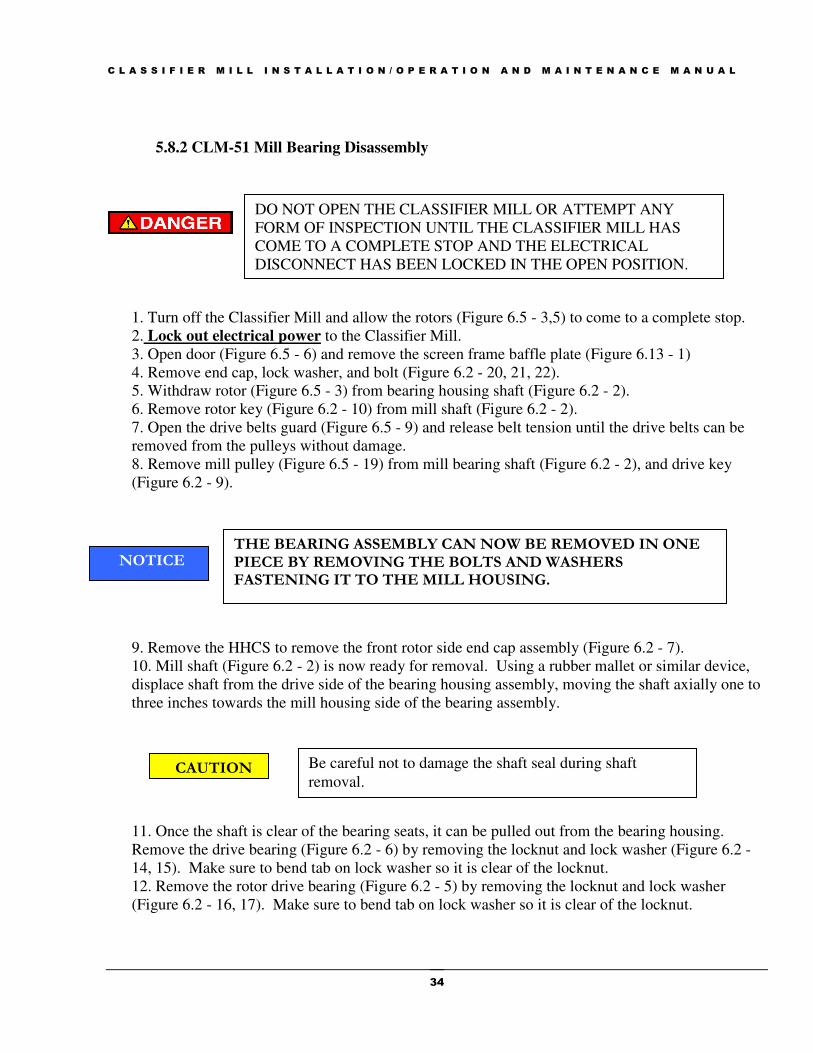
5.8.2 CLM-51 Mill Bearing Disassembly
1. Turn off the Classifier Mill and allow the rotors (Figure 6.5 - 3,5) to come to a complete stop.
2. Lock out electrical power to the Classifier Mill.
3. Open door (Figure 6.5 - 6) and remove the screen frame baffle plate (Figure 6.13 - 1)
4. Remove end cap, lock washer, and bolt (Figure 6.2 - 20, 21, 22).
5. Withdraw rotor (Figure 6.5 - 3) from bearing housing shaft (Figure 6.2 - 2).
6. Remove rotor key (Figure 6.2 - 10) from mill shaft (Figure 6.2 - 2).
7. Open the drive belts guard (Figure 6.5 - 9) and release belt tension until the drive belts can be
removed from the pulleys without damage.
8. Remove mill pulley (Figure 6.5 - 19) from mill bearing shaft (Figure 6.2 - 2), and drive key
(Figure 6.2 - 9).
9. Remove the HHCS to remove the front rotor side end cap assembly (Figure 6.2 - 7).
10. Mill shaft (Figure 6.2 - 2) is now ready for removal. Using a rubber mallet or similar device,
displace shaft from the drive side of the bearing housing assembly, moving the shaft axially one to
three inches towards the mill housing side of the bearing assembly.
11. Once the shaft is clear of the bearing seats, it can be pulled out from the bearing housing.
Remove the drive bearing (Figure 6.2 - 6) by removing the locknut and lock washer (Figure 6.2 -
14, 15). Make sure to bend tab on lock washer so it is clear of the locknut.
12. Remove the rotor drive bearing (Figure 6.2 - 5) by removing the locknut and lock washer
(Figure 6.2 - 16, 17). Make sure to bend tab on lock washer so it is clear of the locknut.
DO NOT OPEN THE CLASSIFIER MILL OR ATTEMPT ANY
FORM OF INSPECTION UNTIL THE CLASSIFIER MILL HAS
COME TO A COMPLETE STOP AND THE ELECTRICAL
DISCONNECT HAS BEEN LOCKED IN THE OPEN POSITION.
THE BEARING ASSEMBLY CAN NOW BE REMOVED IN ONE PIECE BY REMOVING THE BOLTS AND WASHERS FASTENING IT TO THE MILL HOUSING.
NOTICE
CAUTION Be careful not to damage the shaft seal during shaft
removal.

C L A S S I F I E R M I L L I N S T A L L A T I O N / O P E R A T I O N A N D M A I N T E N A N C E M A N U A L
35
5.8.3 CLM-76/101 Mill Bearing Disassembly
1. Turn off the Classifier Mill and allow the rotors (Figure 6.7 - 3,5) to come to a complete stop.
2. Lock out electrical power to the Classifier Mill.
3. Open door (Figure 6.7 - 6) and remove the screen frame baffle plate (Figure 6.14 - 1)
4. Remove end cap, lock washer, and bolt (Figure 6.3 - 20, 21, 22).
5. Withdraw rotor (Figure 6.7 - 3) from bearing housing shaft (Figure 6.3 - 3).
6. Remove rotor key (Figure 6.3 - 10) from mill shaft (Figure 6.3 - 3).
7. Open the drive belts guard (Figure 6.7 - 10) and release belt tension until the drive belts can be
removed from the pulleys without damage.
8. Remove mill pulley (Figure 6.7 - 20) from mill bearing shaft (Figure 6.3 - 3), and drive key
(Figure 6.3 - 11).
9. Remove the HHCS to remove the front rotor side end cap assembly (Figure 6.3 - 12).
10. Mill shaft (Figure 6.3 - 3) is now ready for removal. Using a rubber mallet or similar device,
displace shaft from the drive side of the bearing housing assembly, moving the shaft axially one to
three inches towards the mill housing side of the bearing assembly.
11. Once the shaft is clear of the bearing seats, it can be pulled out from the bearing housing.
Remove the drive bearing (Figure 6.3 - 4) by removing the locknut and lock washer (Figure 6.3 -
5, 6). Make sure to bend tab on lock washer so it is clear of the locknut.
12. Remove the rotor drive bearing (Figure 6.3 - 7) by removing the locknut and lock washer
(Figure 6.3 - 8, 9). Make sure to bend tab on lock washer so it is clear of the locknut.
DO NOT OPEN THE CLASSIFIER MILL OR ATTEMPT ANY
FORM OF INSPECTION UNTIL THE CLASSIFIER MILL HAS
COME TO A COMPLETE STOP AND THE ELECTRICAL
DISCONNECT HAS BEEN LOCKED IN THE OPEN POSITION.
THE BEARING ASSEMBLY CAN NOW BE REMOVED IN ONE PIECE BY REMOVING THE BOLTS AND WASHERS FASTENING IT TO THE MILL HOUSING.
NOTICE
CAUTION Be careful not to damage the shaft seal during shaft
removal.

C L A S S I F I E R M I L L I N S T A L L A T I O N / O P E R A T I O N A N D M A I N T E N A N C E M A N U A L
36
5.8.4 CLM-36 Mill Bearing Reassembly
Assemble bearings (Figure 6.1 - 13, 14) on mill shaft (Figure 6.1 - 2) using the following
procedure:
Before starting the assembly, inspect all parts to be sure they are clean of dirt, grease, burrs, etc.
Lay all parts of the assembly on a clean, dry surface. Inspect the labels on the boxes containing the
bearings to be assembled and be sure they have a green inspection sticker, which ensures Prater
has inspected the critical dimensions. Be sure your hands are free of any grease, metal chips, dirt,
etc. Remove the bearings from the box and verify that the bearings contain the 2Z, C3 and JEM
designations. This is extremely important. Do not use a bearing that does not say 2Z and C3 in
the part designation. Check both sides of the bearing to be sure the shields are not damaged. Once
the bearing is out of the box, always lay it on a clean, dry, flat surface. Bearings have three
external parts: the inner race, the shields and the outer race. When assembling a bearing housing,
the shields on the bearings should never be touched by any tools or even squeezed between the
fingers. This could cause undetected damage to the internal parts of the bearing, resulting in
premature bearing failure. Prater recommends that the critical bearing dimensions (ID, OD, etc.)
be measured to insure they are within the manufacturers tolerances if Prater did not supply the
bearings.
Assembling without an Induction Heater
The pressure applied to the bearing must be on the inner race, and the inner race only. Never put
pressure on the outer race to press a shaft into the inner race of a bearing. Be sure the tool being
used to apply pressure to the inner race is only touching the inner race. Never apply pressure to
one bearing while using the opposite bearing for resistance or as a stop. This will damage the
opposite bearing. The assembly operation starts by pressing the rotor side bearing (Figure 6.1 -
14) onto the bearing housing shaft (Figure 6.1 - 2). Install inner shaft sleeve (Figure 6.1 - 16).
Press the drive side bearing (Figure 6.1 - 13) onto the shaft (Figure 6.1 - 2). Replace lock washers
and lock nuts (Figure 6.1 - 10, 11) so they are tight against the inner race. Make sure the tabs in
the lock washers are bent down onto the lock nut.
Assembling with an Induction Heater
Using an induction heater, heat the rotor side bearing (Figure 6.1 - 14) and insert it on the shaft
(Figure 6.1 - 2) and against the shaft shoulder and let it cool. MAXIMUM temperature is 230° F
(110°C). Slide the shaft sleeve (Figure 6.1 - 16) over the shaft (Figure 6.1 - 2). Heat the drive side
bearing (Figure 6.1 - 13) and insert it on the shaft (Figure 6.1 - 2) and against the shaft sleeve
shoulder (Figure 6.1 - 16) and let it cool. MAXIMUM temperature is 230° F (110°C). Replace
lock washers and lock nuts (Figure 6.1 - 10, 11) so they are tight against the inner race. Make sure
the tab in the lock washer is bent down onto the lock nut.
Once the bearings are pressed onto the shaft, the bearing and shaft assembly can be pressed into
the housing. The first bearing into the housing is the one the resides closest to the pulley. Since

C L A S S I F I E R M I L L I N S T A L L A T I O N / O P E R A T I O N A N D M A I N T E N A N C E M A N U A L
37
this bearing cannot be directly pushed into its seat in the housing, it is important to be sure it is
inserted as straight and accurate as possible. A little care will go a long way.
Next the inner bearing, the one closest to the rotor, is then pushed into the housing by applying
pressure to the outer race of this bearing. Be sure the tool being used to apply pressure to the outer
race is only touching the outer race. Do not use excessive pressure to push this bearing into place.
If the interference is too great, contact a Prater customer service representative for more
information. Do not force the bearing into place with undue pressure. This will only damage the
internal parts of the bearing and results in premature failure of the bearing.
Once the outer bearing is seated in place, install the wave spring so that it rests on the outer race of
the drive side bearing. The bearing end caps are installed to lock the outer race of the bearings into
the housing. Before installing the caps carefully inspect the inpro seals to ensure that they are not
worn or damaged and replace if necessary. Install the bearing caps with the proper hardware.
Reinstall bearing assembly into the mill body and reconnect the air purge lines.
Replace rotor (Figure 6.5 - 3) and install end cap, lock washer, and bolt (Figure 6.1 - 9, 19, 20).
Check for smooth rotor rotation and zero endplay. Install and tension the drive belts then close
and secure the drive belts guard.
5.8.5 CLM-51 Mill Bearing Reassembly
Assemble bearings (Figure 6.2 - 5, 6) on mill shaft (Figure 6.2 - 2) using the following procedure:
Before starting the assembly, inspect all parts to be sure they are clean of dirt, grease, burrs, etc.
Lay all parts of the assembly on a clean, dry surface. Inspect the labels on the boxes containing the
bearings to be assembled and be sure they have a green inspection sticker, which ensures Prater
has inspected the critical dimensions. Be sure your hands are free of any grease, metal chips, dirt,
etc. Remove the bearings from the box and verify that the bearings contain the 2Z, C3 and JEM
designations. This is extremely important. Do not use a bearing that does not say 2Z and C3 in
the part designation. Check both sides of the bearing to be sure the shields are not damaged. Once
the bearing is out of the box, always lay it on a clean, dry, flat surface. Bearings have three
external parts: the inner race, the shields and the outer race. When assembling a bearing housing,
the shields on the bearings should never be touched by any tools or even squeezed between the
fingers. This could cause undetected damage to the internal parts of the bearing, resulting in
premature bearing failure. Prater recommends that the critical bearing dimensions (ID, OD, etc.)
be measured to insure they are within the manufacturers tolerances if Prater did not supply the
bearings.
Assembling without an Induction Heater
Be careful not to damage the shaft seal during shaft
replacement into the mill body.
CAUTION
C L A S S I F I E R M I L L I N S T A L L A T I O N / O P E R A T I O N A N D M A I N T E N A N C E M A N U A L
38
The pressure applied to the bearing must be on the inner race, and the inner race only. Never put
pressure on the outer race to press a shaft into the inner race of a bearing. Be sure the tool being
used to apply pressure to the inner race is only touching the inner race. Never apply pressure to
one bearing while using the opposite bearing for resistance or as a stop. This will damage the
opposite bearing. The assembly operation starts by pressing the rotor side bearing (Figure 6.2 - 5)
onto the bearing housing shaft (Figure 6.2 - 2). Install the lock washer and lock nut (Figure 6.2 -
16, 17) so they are tight against the inner race. Press the drive side bearing (Figure 6.2 - 6) onto
the shaft (Figure 6.2 - 2). Replace lock washers and lock nuts (Figure 6.2 - 14, 15) so they are
tight against the inner race. Make sure the tabs in the lock washers are bent down onto the lock
nut.
Assembling with an Induction Heater
Using an induction heater, heat the rotor side bearing (Figure 6.2 - 5) and insert it on the shaft
(Figure 6.2 - 2) and against the shaft shoulder and let it cool. MAXIMUM temperature is 230° F
(110°C). Install the lock washer and lock nut (Figure 6.2 - 16, 17) so they are tight against the
inner race. Heat the drive side bearing (Figure 6.2 - 6) and insert it on the shaft (Figure 6.2 - 2)
and against the shaft shoulder and let it cool. MAXIMUM temperature is 230° F (110°C).
Replace lock washers and lock nuts (Figure 6.2 - 14, 15) so they are tight against the inner race.
Make sure the tab in the lock washer is bent down onto the lock nut.
Once the bearings are pressed onto the shaft, the bearing and shaft assembly can be pressed into
the housing. The first bearing into the housing is the one the resides closest to the pulley. Since
this bearing cannot be directly pushed into its seat in the housing, it is important to be sure it is
inserted as straight and accurate as possible. A little care will go a long way.
Next the inner bearing, the one closest to the rotor, is then pushed into the housing by applying
pressure to the outer race of this bearing. Be sure the tool being used to apply pressure to the outer
race is only touching the outer race. Do not use excessive pressure to push this bearing into place.
If the interference is too great, contact a Prater customer service representative for more
information. Do not force the bearing into place with undue pressure. This will only damage the
internal parts of the bearing and results in premature failure of the bearing.
Once the outer bearing is seated in place, install the wave spring so that it rests on the outer race of
the drive side bearing. The bearing end caps are installed to lock the outer race of the bearings into
the housing. Before installing the caps carefully inspect the inpro seals to ensure that they are not
worn or damaged and replace if necessary. Install the bearing caps with the proper hardware.
Reinstall bearing assembly into the mill body and reconnect the air purge lines.
Be careful not to damage the shaft seal during shaft
replacement into the mill body. CAUTION

C L A S S I F I E R M I L L I N S T A L L A T I O N / O P E R A T I O N A N D M A I N T E N A N C E M A N U A L
39
Replace rotor (Figure 6.5 - 3) and install end cap, lock washer, and bolt (Figure 6.2 - 20, 21, 22).
Check for smooth rotor rotation and zero endplay. Install and tension the drive belts then close
and secure the drive belts guard.
5.8.6 CLM-76/101 Mill Bearing Reassembly
Assemble bearings (Figure 6.3 - 4, 7)) on mill shaft (Figure 6.3 - 3) using the following procedure:
Before starting the assembly, inspect all parts to be sure they are clean of dirt, grease, burrs, etc.
Lay all parts of the assembly on a clean, dry surface. Inspect the labels on the boxes containing the
bearings to be assembled and be sure they have a green inspection sticker, which ensures Prater
has inspected the critical dimensions. Be sure your hands are free of any grease, metal chips, dirt,
etc. Remove the bearings from the box and verify that the bearings contain the 2Z, C3 and JEM
designations. This is extremely important. Do not use a bearing that does not say 2Z and C3 in
the part designation. Check both sides of the bearing to be sure the shields are not damaged. Once
the bearing is out of the box, always lay it on a clean, dry, flat surface. Bearings have three
external parts: the inner race, the shields and the outer race. When assembling a bearing housing,
the shields on the bearings should never be touched by any tools or even squeezed between the
fingers. This could cause undetected damage to the internal parts of the bearing, resulting in
premature bearing failure. Prater recommends that the critical bearing dimensions (ID, OD, etc.)
be measured to insure they are within the manufacturers tolerances if Prater did not supply the
bearings.
Assembling without an Induction Heater
The pressure applied to the bearing must be on the inner race, and the inner race only. Never put
pressure on the outer race to press a shaft into the inner race of a bearing. Be sure the tool being
used to apply pressure to the inner race is only touching the inner race. Never apply pressure to
one bearing while using the opposite bearing for resistance or as a stop. This will damage the
opposite bearing. The assembly operation starts by pressing the rotor side bearing (Figure 6.3 - 7)
onto the bearing housing shaft (Figure 6.3 - 3). Install the lock washer and lock nut (Figure 6.3 - 8,
9) so they are tight against the inner race. Press the drive side bearing (Figure 6.3 - 4) onto the
shaft (Figure 6.3 - 3). Replace lock washers and lock nuts (Figure 6.3 - 5, 6) so they are tight
against the inner race. Make sure the tabs in the lock washers are bent down onto the lock nut.
Assembling with an Induction Heater
Using an induction heater, heat the rotor side bearing (Figure 6.3 - 7) and insert it on the shaft
(Figure 6.3 - 3) and against the shaft shoulder and let it cool. MAXIMUM temperature is 230° F
(110°C). Install the lock washer and lock nut (Figure 6.3 - 8, 9) so they are tight against the inner
race. Heat the drive side bearing (Figure 6.3 - 4) and insert it on the shaft (Figure 6.3 - 3) and
against the shaft shoulder and let it cool. MAXIMUM temperature is 230° F (110°C). Replace

C L A S S I F I E R M I L L I N S T A L L A T I O N / O P E R A T I O N A N D M A I N T E N A N C E M A N U A L
40
lock washers and lock nuts (Figure 6.3 - 5, 6) so they are tight against the inner race. Make sure
the tab in the lock washer is bent down onto the lock nut.
Once the bearings are pressed onto the shaft, the bearing and shaft assembly can be pressed into
the housing. The first bearing into the housing is the one the resides closest to the pulley. Since
this bearing cannot be directly pushed into its seat in the housing, it is important to be sure it is
inserted as straight and accurate as possible. A little care will go a long way.
Next the inner bearing, the one closest to the rotor, is then pushed into the housing by applying
pressure to the outer race of this bearing. Be sure the tool being used to apply pressure to the outer
race is only touching the outer race. Do not use excessive pressure to push this bearing into place.
If the interference is too great, contact a Prater customer service representative for more
information. Do not force the bearing into place with undue pressure. This will only damage the
internal parts of the bearing and results in premature failure of the bearing.
Once the outer bearing is seated in place, install the wave spring so that it rests on the outer race of
the drive side bearing. The bearing end caps are installed to lock the outer race of the bearings into
the housing. Before installing the caps carefully inspect the inpro seals to ensure that they are not
worn or damaged and replace if necessary. Install the bearing caps with the proper hardware.
Reinstall bearing assembly into the mill body and reconnect the air purge lines.
Replace rotor (Figure 6.7 - 3) and install end cap, lock washer, and bolt (Figure 6.3 - 20, 21, 22).
Check for smooth rotor rotation and zero endplay. Install and tension the drive belts then close
and secure the drive belts guard.
5.8.7 CLM-76/ 101Classifier Bearing Dissassembly
1. Turn off the Classifier Mill and allow the rotors (Figure 6.7 - 3,5) to come to a complete stop.
2. Lock out electrical power to the Classifier Mill.
3. Open door (Figure 6.7 - 6) and remove the lock washers, screws, and end cap (Figure 6.11 - 3,
14, 20) that attach the classifier rotor (Figure 6.7 - 5) to the classifier bearing assembly (Figure 6.7
- 7).
Be careful not to damage the shaft seal during shaft
replacement into the mill body. CAUTION
DO NOT OPEN THE CLASSIFIER MILL OR ATTEMPT ANY
FORM OF INSPECTION UNTIL THE CLASSIFIER MILL HAS
COME TO A COMPLETE STOP AND THE ELECTRICAL
DISCONNECT HAS BEEN LOCKED IN THE OPEN POSITION.

C L A S S I F I E R M I L L I N S T A L L A T I O N / O P E R A T I O N A N D M A I N T E N A N C E M A N U A L
41
4. Withdraw the classifier rotor (Figure 6.7 - 5) from the bearing housing shaft (Figure 6.4 - 1).
5. Remove rotor key (Figure 6.4 - 18) from mill shaft (Figure 6.4 - 1).
6. Open the drive belts guard (Figure 6.7 - 11) and release belt tension by adjusting the classifier
motor (Figure 6.7 - 16) until the drive belts can be removed from the pulleys without damage.
7. Remove the classifier drive pulley from the classifier bearing shaft (Figure 6.4 - 1) and remove
the drive key (Figure 6.4 - 17).
8. Remove the HHCS to remove the front rotor side end cap assembly (Figure 6.4 - 9) and spacer
(Figure 6.4 - 7) from the classifier bearing assembly.
9. The classifier bearing shaft (Figure 6.4 - 1) is now ready for removal. Using a rubber mallet or
similar device, displace shaft from the drive side of the bearing housing assembly, moving the
shaft axially one to three inches towards the mill housing side of the bearing assembly.
10. Once the shaft is clear of the bearing seats, it can be pulled out from the bearing housing.
Remove the rotor drive bearing (Figure 6.4 - 4) from the shaft (Figure 6.4 - 1).
11. Remove the drive bearing (Figure 6.4 - 3) by removing the locknut and lock washer (Figure 6.4
- 5, 6). Make sure to bend tab on lock washer so it is clear of the locknut.
5.8.8 CLM-76/ 101 Classifier Bearing Reassembly
Assemble bearings (Figure 6.4 - 3, 4) on mill shaft (Figure 6.4 - 1) using the following procedure:
Before starting the assembly, inspect all parts to be sure they are clean of dirt, grease, burrs, etc.
Lay all parts of the assembly on a clean, dry surface. Inspect the labels on the boxes containing the
bearings to be assembled and be sure they have a green inspection sticker, which ensures Prater
has inspected the critical dimensions. Be sure your hands are free of any grease, metal chips, dirt,
etc. Remove the bearings from the box and verify that the bearings contain the 2Z, C3 and JEM
designations. This is extremely important. Do not use a bearing that does not say 2Z and C3 in
the part designation. Check both sides of the bearing to be sure the shields are not damaged. Once
the bearing is out of the box, always lay it on a clean, dry, flat surface. Bearings have three
external parts: the inner race, the shields and the outer race. When assembling a bearing housing,
the shields on the bearings should never be touched by any tools or even squeezed between the
THE BEARING ASSEMBLY CAN NOW BE REMOVED IN ONE PIECE BY REMOVING THE BOLTS AND WASHERS FASTENING IT TO THE MILL HOUSING.
NOTICE
CAUTION Be careful not to damage the shaft seal during shaft
removal.

C L A S S I F I E R M I L L I N S T A L L A T I O N / O P E R A T I O N A N D M A I N T E N A N C E M A N U A L
42
fingers. This could cause undetected damage to the internal parts of the bearing, resulting in
premature bearing failure. Prater recommends that the critical bearing dimensions (ID, OD, etc.)
be measured to insure they are within the manufacturers tolerances if Prater did not supply the
bearings.
Assembling without an Induction Heater
The pressure applied to the bearing must be on the inner race, and the inner race only. Never put
pressure on the outer race to press a shaft into the inner race of a bearing. Be sure the tool being
used to apply pressure to the inner race is only touching the inner race. Never apply pressure to
one bearing while using the opposite bearing for resistance or as a stop. This will damage the
opposite bearing. The assembly operation starts by pressing the drive side bearing (Figure 6.4 - 3)
onto the bearing housing shaft (Figure 6.4 - 1). Install the lock washer and lock nut (Figure 6.4 - 5,
6) so they are tight against the inner race. Press the rotor side bearing (Figure 6.4 - 4) onto the
shaft (Figure 6.4 - 1). Replace the rotor side end cap and spacer (Figure 6.4 - 9, 7) and make sure
the spacer is pressed firmly against the inner race of the classifier rotor bearing (Figure 6.4 - 4)
before reinstalling the classifier rotor.
Assembling with an Induction Heater
Using an induction heater, heat the drive side bearing (Figure 6.4 - 3) and insert it on the shaft
(Figure 6.4 - 1) and against the shaft shoulder and let it cool. MAXIMUM temperature is 230° F
(110°C). Install the lock washer and lock nut (Figure 6.4 - 5, 6) so they are tight against the inner
race. Heat the rotor side bearing (Figure 6.4 - 4) and insert it on the shaft (Figure 6.4 - 1) and
against the shaft shoulder and let it cool. MAXIMUM temperature is 230° F (110°C). Replace
the rotor side end cap and spacer (Figure 6.4 - 9, 7) and make sure the spacer is pressed firmly
against the inner race of the classifier rotor bearing (Figure 6.4 - 4) before reinstalling the classifier
rotor.
Once the bearings are pressed onto the shaft, the bearing and shaft assembly can be pressed into
the housing. The first bearing into the housing is the one the resides closest to the pulley. Since
this bearing cannot be directly pushed into its seat in the housing, it is important to be sure it is
inserted as straight and accurate as possible. A little care will go a long way.
Next the inner bearing, the one closest to the rotor, is then pushed into the housing by applying
pressure to the outer race of this bearing. Be sure the tool being used to apply pressure to the outer
race is only touching the outer race. Do not use excessive pressure to push this bearing into place.
If the interference is too great, contact a Prater customer service representative for more
information. Do not force the bearing into place with undue pressure. This will only damage the
internal parts of the bearing and results in premature failure of the bearing.
Once the outer bearing is seated in place, install the wave spring so that it rests on the outer race of
the drive side bearing. The bearing end caps are installed to lock the outer race of the bearings into
the housing. Before installing the caps carefully inspect the inpro seals to ensure that they are not

C L A S S I F I E R M I L L I N S T A L L A T I O N / O P E R A T I O N A N D M A I N T E N A N C E M A N U A L
43
worn or damaged and replace if necessary. Install the bearing caps with the proper hardware.
Reinstall bearing assembly into the mill body and reconnect the air purge lines.
Replace the rotor key (Figure 6.4 - 18) onto the mill shaft (Figure 6.4 - 1) and reattach the
classifier rotor (Figure 6.7 - 5) using the lock washers, screws, and end cap (Figure 6.11 - 3, 14,
20). Install and tension the drive belts then close and secure the drive belts guard.
5.8.9 New Bearing Run-In Procedure
Bearing Temperatures
Initial bearing running temperatures and stabilization time will bary depending upon the following
factors:
1. Rotational speed (RPM)
2. Installed bearing internal clearance
3. Grease fill volume
4. Bearing size
5. Ambient temperature
It is recommended to start new bearings running at half speed, if a VFD is available, for about one
hour. After an hour, increase to full speed and run until both bearing temperatures stabilize below
140° F. If VFD is not available, try an initial warm-up procedure of power-on, then power-off, the
mill drive motor to achieve an average break-in speed of about half the normal running speed for
the first 15 minutes of running time.
Bearings with less internal clearance will run warmer initially and take longer to stabilize.
Generally, larger bearings will run warmer than smaller bearings, since the rolling elements must
spin at a higher velocity.
It is not uncommon for a new bearing to reach 160° F during initial run-in, but in no case should a
bearing temperature be allowed to exceed 180° F for an extended period of time. Grease may
begin to bleed above 180° F. Grease life is best if the bearing temperature stabilizes below 140° F.
Depending upon the variables given above, bearing temperatures should reduce to a stabilized
running temperature below 140° F within the first 24 hours of operation. The final stabilized
temperature for a particular bearing will depend on the ambient temperature and bearing internal
clearance.
Be careful not to damage the shaft seal during shaft
replacement into the mill body. CAUTION

C L A S S I F I E R M I L L I N S T A L L A T I O N / O P E R A T I O N A N D M A I N T E N A N C E M A N U A L
44
5.9 Belt Tension
1. Turn off the Classifier Mill and allow the rotors (Figures 6.4 & 6.6 - 3, 5) to come to a
complete stop.
2. Lock out electrical power to the Classifier Mill.
3. Open mill drive guard door by using a tool to remove fasteners that attach front guard face to
the main guard body.
4. Press firmly on the mid-point of the belt and measure the belt deflection. Deflection should be
1/4" or less.
5. If deflection is more than 1/4", loosen the motor mounting bolts, tighten the belt and tighten the
mounting bolts.
6. Reattach drive guard door.
7. Repeat above steps for classifier rotor drive.
DO NOT OPEN THE CLASSIFIER MILL OR ATTEMPT ANY
FORM OF INSPECTION UNTIL THE CLASSIFIER MILL HAS
COME TO A COMPLETE STOP AND THE ELECTRICAL
DISCONNECT HAS BEEN LOCKED IN THE OPEN POSITION.

C L A S S I F I E R M I L L I N S T A L L A T I O N / O P E R A T I O N A N D M A I N T E N A N C E M A N U A L
45
Section 6: Drawings and Parts List
The following figures and illustrations are provided to assist in the operation and maintenance of
Prater Classifier Mills as well as a general reference for any spare or replacement parts for Prater
Classifier Mills. For specific Classifier Mill questions please contact Prater Customer Service.
Section
6

C L A S S I F I E R M I L L I N S T A L L A T I O N / O P E R A T I O N A N D M A I N T E N A N C E M A N U A L
46
Figure 6.1: CLM-36 Exploded Mill Bearing Assembly

C L A S S I F I E R M I L L I N S T A L L A T I O N / O P E R A T I O N A N D M A I N T E N A N C E M A N U A L
47
Figure 6.2: CLM-51 Exploded Mill Bearing Assembly
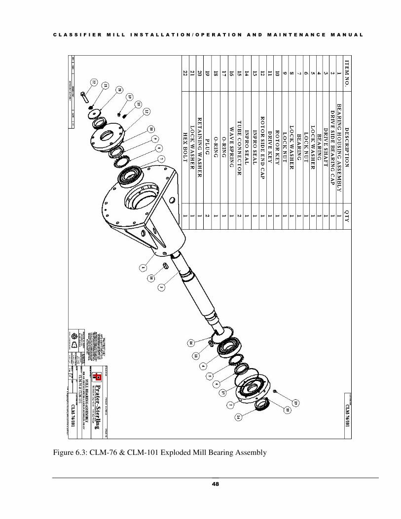
C L A S S I F I E R M I L L I N S T A L L A T I O N / O P E R A T I O N A N D M A I N T E N A N C E M A N U A L
48
Figure 6.3: CLM-76 & CLM-101 Exploded Mill Bearing Assembly

C L A S S I F I E R M I L L I N S T A L L A T I O N / O P E R A T I O N A N D M A I N T E N A N C E M A N U A L
49
Figure 6.4: CLM-76 & CLM-101 Exploded Classifier Bearing Assembly

C L A S S I F I E R M I L L I N S T A L L A T I O N / O P E R A T I O N A N D M A I N T E N A N C E M A N U A L
50
Figure 6.5: CLM-36 & CLM-51 Main Assembly Exploded View

C L A S S I F I E R M I L L I N S T A L L A T I O N / O P E R A T I O N A N D M A I N T E N A N C E M A N U A L
51
Table 6.6: CLM-36 & CLM-51 Main Assembly Parts List
CLM-36 & CLM-51 Main Assembly Parts List
Item No. Description Qty.
1 Housing Assembly 1
2 Mill Bearing Assembly 1
3 Mill Rotor Assembly 1
4 Screen Frame Assembly 1
5 Classifier Rotor Assembly 1
6 Door Assembly 1
7 Product Inlet 1
8 Secondary Air Inlet 1
9 Mill Drive Guard Assembly 1
10 Classifier Motor 1
11 Door Seal 1
12 Door Plate 1
13 Classifier Mill Base 1
14 Housing Body Seal 1
15 Mill Motor Base 1
16 Mill Motor 1
17 Motor Drive Pulley 1
18 Motor Drive Pulley Bushing 1
19 Rotor Drive Pulley 1
20 Rotor Drive Pulley Bushing 1
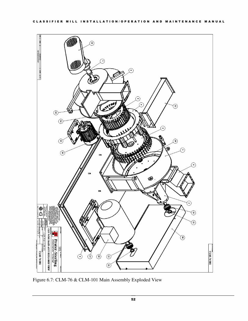
C L A S S I F I E R M I L L I N S T A L L A T I O N / O P E R A T I O N A N D M A I N T E N A N C E M A N U A L
52
Figure 6.7: CLM-76 & CLM-101 Main Assembly Exploded View
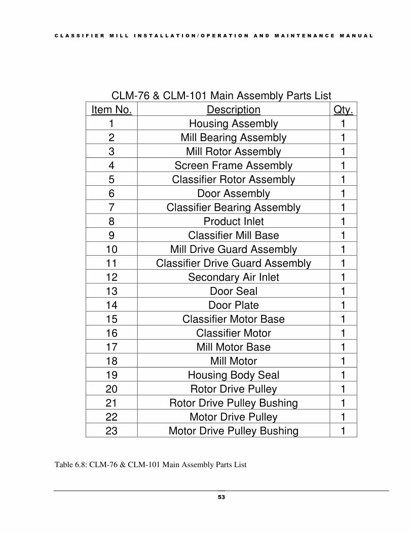
C L A S S I F I E R M I L L I N S T A L L A T I O N / O P E R A T I O N A N D M A I N T E N A N C E M A N U A L
53
Table 6.8: CLM-76 & CLM-101 Main Assembly Parts List
CLM-76 & CLM-101 Main Assembly Parts List
Item No. Description Qty.
1 Housing Assembly 1
2 Mill Bearing Assembly 1
3 Mill Rotor Assembly 1
4 Screen Frame Assembly 1
5 Classifier Rotor Assembly 1
6 Door Assembly 1
7 Classifier Bearing Assembly 1
8 Product Inlet 1
9 Classifier Mill Base 1
10 Mill Drive Guard Assembly 1
11 Classifier Drive Guard Assembly 1
12 Secondary Air Inlet 1
13 Door Seal 1
14 Door Plate 1
15 Classifier Motor Base 1
16 Classifier Motor 1
17 Mill Motor Base 1
18 Mill Motor 1
19 Housing Body Seal 1
20 Rotor Drive Pulley 1
21 Rotor Drive Pulley Bushing 1
22 Motor Drive Pulley 1
23 Motor Drive Pulley Bushing 1

C L A S S I F I E R M I L L I N S T A L L A T I O N / O P E R A T I O N A N D M A I N T E N A N C E M A N U A L
54
Figure 6.9: CLM Mill Rotor Assembly Exploded View and Parts List

C L A S S I F I E R M I L L I N S T A L L A T I O N / O P E R A T I O N A N D M A I N T E N A N C E M A N U A L
55
Figure 6.10: CLM-36 Classifier Rotor Assembly Exploded View and Parts List
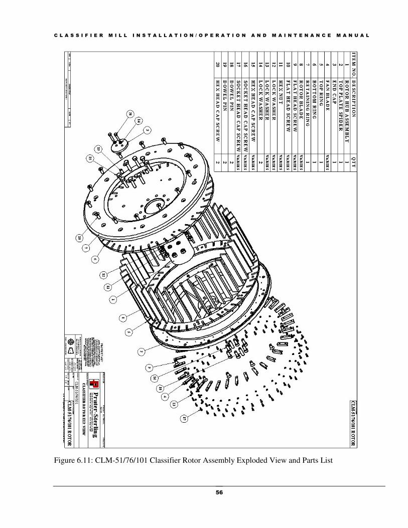
C L A S S I F I E R M I L L I N S T A L L A T I O N / O P E R A T I O N A N D M A I N T E N A N C E M A N U A L
56
Figure 6.11: CLM-51/76/101 Classifier Rotor Assembly Exploded View and Parts List
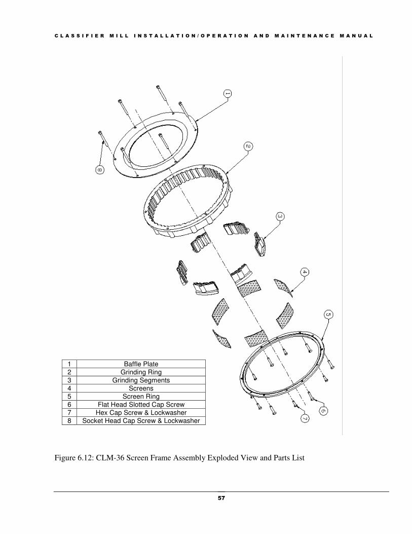
C L A S S I F I E R M I L L I N S T A L L A T I O N / O P E R A T I O N A N D M A I N T E N A N C E M A N U A L
57
Figure 6.12: CLM-36 Screen Frame Assembly Exploded View and Parts List
1 Baffle Plate
2 Grinding Ring
3 Grinding Segments
4 Screens
5 Screen Ring
6 Flat Head Slotted Cap Screw
7 Hex Cap Screw & Lockwasher
8 Socket Head Cap Screw & Lockwasher

C L A S S I F I E R M I L L I N S T A L L A T I O N / O P E R A T I O N A N D M A I N T E N A N C E M A N U A L
58
Figure 6.13: CLM-51 Screen Frame Assembly Exploded View and Parts List
1 Baffle Plate 2 Grinding Ring 3 Grinding Jaw 4 Screen 5 Screen Spacer 6 Screen Ring 7 HHCS & Lockwasher

C L A S S I F I E R M I L L I N S T A L L A T I O N / O P E R A T I O N A N D M A I N T E N A N C E M A N U A L
59
Figure 6.14: CLM-76/101 Screen Frame Assembly Exploded View and Parts List
1 Baffle Plate Assembly
2 Grinding Ring Segment Assemblies 3 Grinding Plate Assemblies
4 Screens 5 Spacer Pin
6 Segment Spacer 7 Screw & Lockwasher

C L A S S I F I E R M I L L I N S T A L L A T I O N / O P E R A T I O N A N D M A I N T E N A N C E M A N U A L
60
Figure 6.15: CLM Screenless Screen Frame Assembly Exploded View and Parts List
1 Hex Nut & Lockwasher 2 Baffle Plate Assembly 3 Front Grinding Ring 4 Spacer 5 Rear Grinding Ring 6 Guide Pin & Lockwasher

C L A S S I F I E R M I L L I N S T A L L A T I O N / O P E R A T I O N A N D M A I N T E N A N C E M A N U A L
61
Figure 6.16: CLM Operating Principle

C L A S S I F I E R M I L L I N S T A L L A T I O N / O P E R A T I O N A N D M A I N T E N A N C E M A N U A L
62
ITEM NO. DESCRIPTION ITEM NO. DESCRIPTION
1. Mill Pulley 25. Lockwasher
2. Body Assembly/Housing 26. Drive Bearing
3. Sensor Disc 27. Bearing Housing
4. Collar 28. Key
5. Yoke Pin 29. Mill Shaft
6. Collar 30. Key
7. Yoke Door Latch 31. Grease Retainer
8. Threaded Rod 32. Rotor Bearing
9. Latch Knob 33. Gasket
10. Door Seal 34. Bearing Cover
11. Door Seal 35. Lockwasher
12. Classifier 35A. Locknut
13. Screw 36. Screw
14. Main Ring 37. Labyrinth
15. Grinding Jaw 38. Rotor Spacer
16. Screen 39. End Cap
17. Grinding Ring 40. Lockwasher
18. Screw 41. Screw
18A. Baffle Ring/Plate 43. Rotor Blade
19. Screw 44. Screw
20. Lockwasher 45. Retainer Ring
21. Snap Ring 46. Rotor Disc
22. Rear Bearing Cap 47. Screw
23. Seal 48. Lockwasher
24. Locknut
Table 6.17: CLM-36, CLM-51, and CLM-101 Assembly Parts List

C L A S S I F I E R M I L L I N S T A L L A T I O N / O P E R A T I O N A N D M A I N T E N A N C E M A N U A L
63
Figure 6.18: CLM-36 Components

C L A S S I F I E R M I L L I N S T A L L A T I O N / O P E R A T I O N A N D M A I N T E N A N C E M A N U A L
64
Figure 6.19: CLM-51 Components
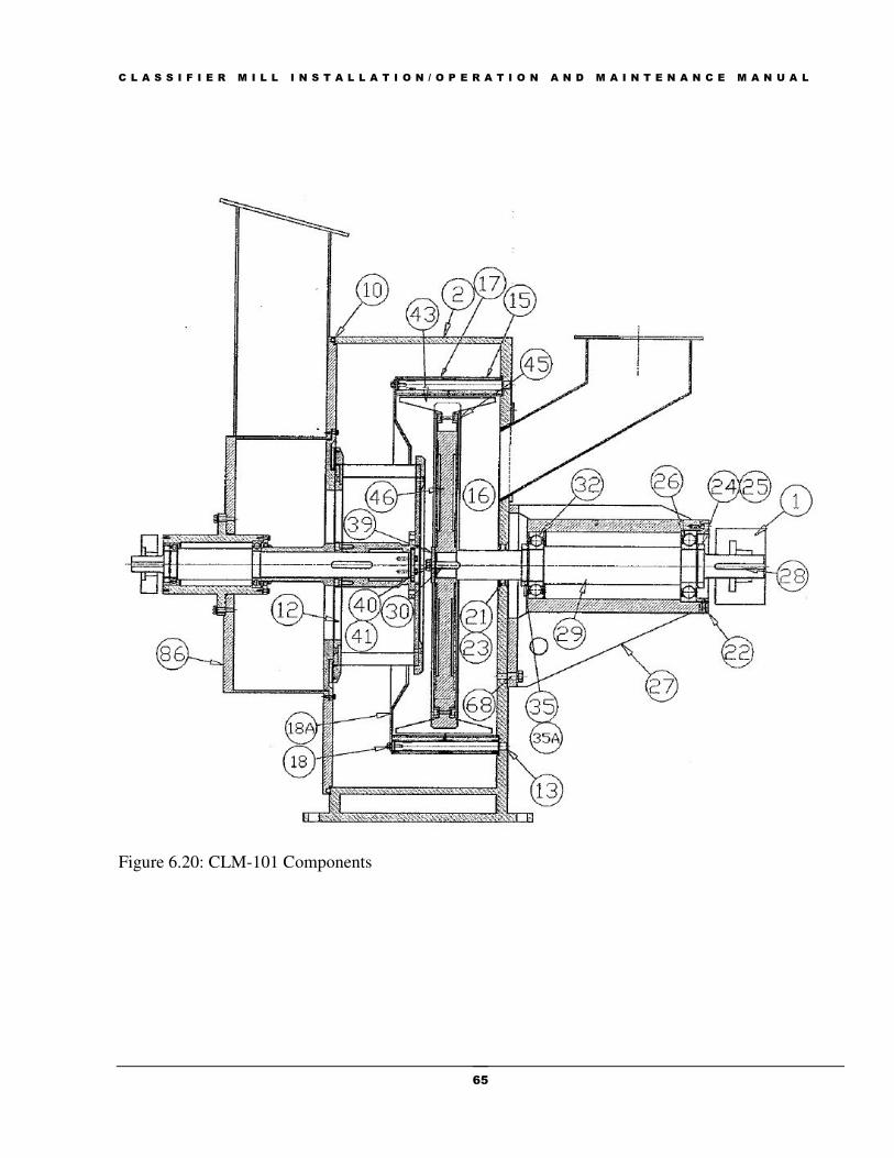
C L A S S I F I E R M I L L I N S T A L L A T I O N / O P E R A T I O N A N D M A I N T E N A N C E M A N U A L
65
Figure 6.20: CLM-101 Components

C L A S S I F I E R M I L L I N S T A L L A T I O N / O P E R A T I O N A N D M A I N T E N A N C E M A N U A L
66
ITEM NO. DESCRIPTION ITEM NO. DESCRIPTION
47. Screw 70. Ball Bearing
48. Lockwasher 71. Washer
49. Screw 72. Bearing Housing
50. Screw 73. Top Retainer
51. Retaining 74. Bearing
52. Bottom Carrier Ring 75. Lockwasher
53. Rotor Blade 76. Locknut
54. Hub 77. Flinger
55. Retaining Ring 78. Rear Bearing Cap
56. Spider Ring 79. Washer
57. Screw 80. Screw
58. Spacer 81. Pulley
59. Seal 82. Screw
60. Fan Blade 83. Belt
61. Washer 84. Pulley
62. Screw 85. Drive Guard
63. Spacer 86. Door
64. Key 87. Door Plate
65. Rotor Shaft 88. Lockwasher
65A. Spacer 89. Washer
66. Labyrinth 90. Screw
67. Screw 91. Motor
68. Screw 92. Taperlock Bushing
69. Bearing Cover 93. Taperlock Sheave
Table 6.21: CLM-36, CLM-51, and CLM-101 Classifier Parts List
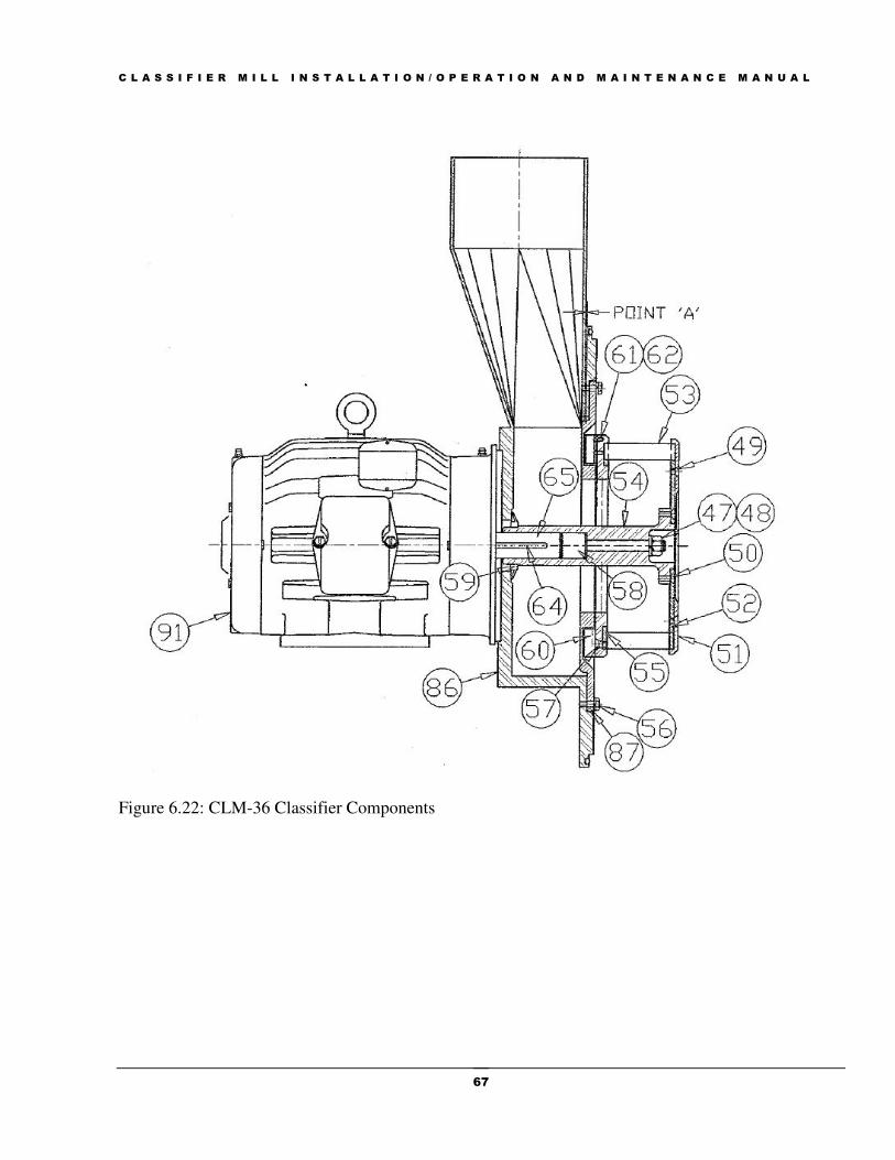
C L A S S I F I E R M I L L I N S T A L L A T I O N / O P E R A T I O N A N D M A I N T E N A N C E M A N U A L
67
Figure 6.22: CLM-36 Classifier Components

C L A S S I F I E R M I L L I N S T A L L A T I O N / O P E R A T I O N A N D M A I N T E N A N C E M A N U A L
68
Figure 6.23: CLM-51 Classifier Components

C L A S S I F I E R M I L L I N S T A L L A T I O N / O P E R A T I O N A N D M A I N T E N A N C E M A N U A L
69
Figure 6.24: CLM-101 Classifier Components
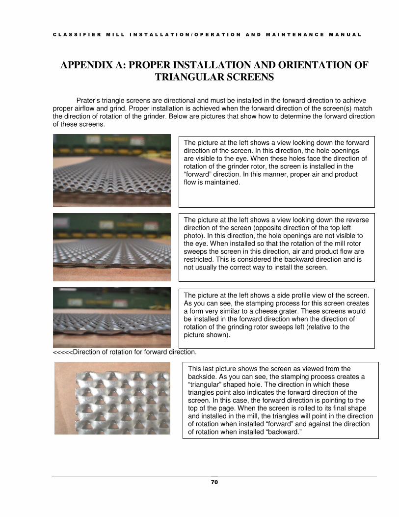
C L A S S I F I E R M I L L I N S T A L L A T I O N / O P E R A T I O N A N D M A I N T E N A N C E M A N U A L
70
APPENDIX A: PROPER INSTALLATION AND ORIENTATION OF
TRIANGULAR SCREENS
Prater’s triangle screens are directional and must be installed in the forward direction to achieve proper airflow and grind. Proper installation is achieved when the forward direction of the screen(s) match the direction of rotation of the grinder. Below are pictures that show how to determine the forward direction of these screens.
<<<<<Direction of rotation for forward direction.
The picture at the left shows a view looking down the forward direction of the screen. In this direction, the hole openings are visible to the eye. When these holes face the direction of rotation of the grinder rotor, the screen is installed in the “forward” direction. In this manner, proper air and product flow is maintained.
The picture at the left shows a view looking down the reverse direction of the screen (opposite direction of the top left photo). In this direction, the hole openings are not visible to the eye. When installed so that the rotation of the mill rotor sweeps the screen in this direction, air and product flow are restricted. This is considered the backward direction and is not usually the correct way to install the screen.
The picture at the left shows a side profile view of the screen. As you can see, the stamping process for this screen creates a form very similar to a cheese grater. These screens would be installed in the forward direction when the direction of rotation of the grinding rotor sweeps left (relative to the picture shown).
This last picture shows the screen as viewed from the backside. As you can see, the stamping process creates a “triangular” shaped hole. The direction in which these triangles point also indicates the forward direction of the screen. In this case, the forward direction is pointing to the top of the page. When the screen is rolled to its final shape and installed in the mill, the triangles will point in the direction of rotation when installed “forward” and against the direction of rotation when installed “backward.”
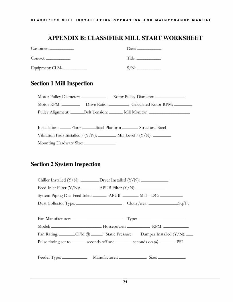
C L A S S I F I E R M I L L I N S T A L L A T I O N / O P E R A T I O N A N D M A I N T E N A N C E M A N U A L
71
APPENDIX B: CLASSIFIER MILL START WORKSHEET
Customer: ___________ Date: ___________
Contact: ___________ Title: ___________
Equipment: CLM-___________ S/N: ___________
Section 1 Mill Inspection
Motor Pulley Diameter: ___________ Rotor Pulley Diameter: _____________
Motor RPM: ________ Drive Ratio: _________ Calculated Rotor RPM: ________
Pulley Alignment: ______Belt Tension: ______ Mill Monitor: __________________
Installation: _____Floor ______Steel Platform _______ Structural Steel
Vibration Pads Installed ? (Y/N): ________ Mill Level ? (Y/N): ________
Mounting Hardware Size: ______________
Section 2 System Inspection
Chiller Installed (Y/N): ________ Dryer Installed (Y/N): ____________
Feed Inlet Filter (Y/N): ________ APUB Filter (Y/N): _____________
System Piping Dia: Feed Inlet: ______ APUB: _______ Mill – DC: __________
Dust Collector Type: ____________________ Cloth Area: _____________Sq/Ft
Fan Manufacturer: ______________________ Type: ____________________
Model: ______________________ Horsepower: __________ RPM: ___________
Fan Rating: _______CFM @ _____” Static Pressure Damper Installed (Y/N): ___
Pulse timing set to ______ seconds off and _______ seconds on @ _______ PSI
Feeder Type: ___________ Manufacturer: ____________ Size: ____________
C L A S S I F I E R M I L L I N S T A L L A T I O N / O P E R A T I O N A N D M A I N T E N A N C E M A N U A L
72
APPENDIX C: AIRFLOW ABSTRACT
Proper airflow is essential for efficient production. This discussion outlines methods for measuring
airflow in an operating system.
Air Flow and Air Pressure Relationships
We must first review some basic principles of airflow and pressure, and then show how to obtain the
required value of Velocity Pressure. In the illustrations that follow, we show a simple U-shaped glass
tube connected to an air duct with flexible tubing. The U-tube holds water and has marked graduations
showing inched of water column on both legs of the tube.
In determining static pressure, one end of the U-tube is open to atmospheric pressure and the other end
is connected to a port at the side of the air duct.
The total pressure measurement differs from static pressure in that a rigid elbow extends into the duct
to gage the force of the moving air stream as shown in Figure C-1.
The velocity pressure measurement connects both ends of the U-tube to the air duct; one to the side
and the other in the air stream with a rigid elbow as shown in Figure C-1.
The three types of pressures are related in the manner:
Ptot = Pvel + Pst
Pvel = Ptot - Pst
Sample Calculation
The following example shows how to calculate airflow in cubic feet per minute.
If using the U-tube as shown in Figure C-1, you measure:
Pst at 14.0” W.C. (inches water column)
Ptot at -12.5” W.C. (inches water column)
And you know
The duct diameter to be 10”
Then, you can use the formula:
Ptot = Pvel + Pst
To calculate the correct airflow in cubic feet per minute as follows:
-12.5 = Pvel + (-14.0)
Pvel = 14 - 12.5 = 1.5
Using Table C-1, locate the intersecting columns for Pvel at 1.5, and Duct Diameter at 10".
The Air Flow for this example is 2565 CFM.
Velocity Pressure can also be measured with a pitot tube in a configuration such as shown in Figure C-
1. The determination shown has the advantages of simplicity and of providing a direct reading of
Velocity Pressure in inches of water column.
Velocity Pressure and Air Volume
With a value for Pvel obtained by any appropriate method, Table C-1 allows a direct reading of
airflow in cubic feet per minute. The table covers duct diameters 4 to 18 inches and Velocity Pressures
up to 2-1/2 inches of water column.

C L A S S I F I E R M I L L I N S T A L L A T I O N / O P E R A T I O N A N D M A I N T E N A N C E M A N U A L
73
The examples shown describe the Negative air systems. In Positive systems the total pressure would
be higher than the static pressure.
4 5 6 8 10 12 14 16 18
3.83 4.83 5.83 7.79 9.79 11.79 13.79 15.79 17.74
.081 .128 .187 .331 .523 .758 1.037 1.360 1.716
Velocity Air
Pressure Speed
(Inches WC) (fpm)
.10 1266 103 162 237 419 662 960 1313 1722 2172
.20 1791 145 229 335 593 937 1358 1857 2436 3073
.30 2194 178 281 410 726 1147 1663 2275 2984 3765
.40 2533 205 324 474 838 1325 1920 2627 3445 4347
.50 2832 229 362 530 937 1481 2147 2937 3852 4860
.60 3102 251 397 580 1027 1622 2351 3217 4219 5323
.70 3351 271 429 627 1109 1753 2540 3475 4557 5750
.80 3582 290 458 670 1186 1873 2715 3715 4872 6147
.90 3799 308 486 710 1257 1987 2880 3940 5167 6519
1.00 4005 324 513 749 1326 2095 3036 4153 5447 6873
1.10 4200 340 538 785 1390 2197 3184 4355 5712 7207
1.20 4387 355 562 820 1452 2294 3325 4549 5966 7528
1.30 4566 370 584 854 1511 2388 3461 4735 6210 7835
1.40 4739 384 607 886 1569 2478 3592 4914 6445 8132
1.50 4905 397 628 917 1624 2565 3718 5086 6671 8417
1.60 5066 410 648 947 1677 2650 3840 5253 6890 8693
1.70 5222 423 668 977 1728 2731 3958 5415 7102 8961
1.80 5373 435 688 1005 1778 2810 4073 5572 7307 9220
1.90 5521 447 707 1032 1827 2887 4185 5725 7509 9474
2.0 5664 459 725 1059 1875 2962 4293 5874 7703 9719
2.10 5804 470 743 1085 1921 3035 4399 6019 7893 9960
2.20 5940 481 760 1111 1966 3107 4503 6160 8078 10193
2.30 6074 492 777 1136 2010 3177 4604 6299 8261 10423
2.40 6205 503 794 1160 2054 3245 4703 6435 8439 10648
Air Flow CFM (Cubic Feet per Minute)
Duct Area (SQ. FT)
Duct OD (Inches)
Duct ID (Inches)
Table C-1
Air Volume Measurements
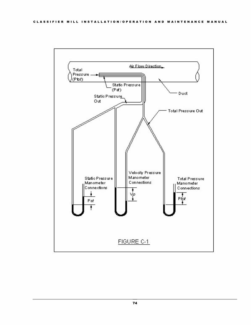
C L A S S I F I E R M I L L I N S T A L L A T I O N / O P E R A T I O N A N D M A I N T E N A N C E M A N U A L
74

C L A S S I F I E R M I L L I N S T A L L A T I O N / O P E R A T I O N A N D M A I N T E N A N C E M A N U A L
75
APPENDIX D: TROUBLESHOOTING GUIDE
This section covers some common operating problems that might be encountered with the Prater
Industries, Inc. Classifier Mill. This is offered as a general guide to analyzing and correcting common
problems with the Classifier Mill. This is not intended as a guide to every problem you might
encounter with the milling system. If after reviewing this section and making any necessary
adjustments you have not identified the specific cause of the problem contact Prater Industries, Inc.
Customer Service for further assistance.
Ground Product Too Coarse
1. Obtain a sample of the feed material and perform an evaluation of the sample for particle size,
moisture, and oil content. If any of these parameters have changed an adjustment to the mill
speed or screen frame may be necessary. Prater recommends contacting Prater Industries, Inc.
Customer Service for further guidance.
2. Check to ensure the proper screen size and screen frame configuration is being used.
3. Check for wear on the rotor blades, grinding jaws, and screens.
4. Check the speed of the mill using a tachometer to determine if the speed has changed due to
electrical or belt slippage problems.
5. Check to ensure the mill is being fed the proper rate, and does not have large variations in the
current draw due to pulsing of the feed.
6. Check to ensure proper air volume entering the mill with the feed.
Ground Product Too Fine
1. Obtain a sample of the feed material and perform an evaluation of the sample for particle size,
moisture, and oil content. If any of these parameters gave changed an adjustment to the mill
speed or screen frame may be necessary. Prater recommends contacting Prater Industries, Inc.
Customer Service for further guidance.
2. Check to ensure the proper screen size and screen frame configuration is being used.
3. Check the speed of the mill using a tachometer to determine if the speed has changed due to
electrical or belt slippage problems.
4. Ensure proper air volume thru mill feed inlet. Check for obstructions in piping or buildup on
the dust collector filters, check the system fan.
Low Capacity
1. Obtain a sample of the feed material and perform an evaluation of the sample for particle size,
moisture, and oil content. If any of these parameters gave changed an adjustment to the mill
speed or screen frame may be necessary. Prater recommends contacting Prater Industries, Inc.
Customer Service for further guidance.
2. Check to ensure the proper screen size and screen frame configuration is being used.

C L A S S I F I E R M I L L I N S T A L L A T I O N / O P E R A T I O N A N D M A I N T E N A N C E M A N U A L
76
3. Check the speed of the mill using a tachometer to determine if the speed has changed due to
electrical or belt slippage problems.
4. Ensure proper air volume thru mill feed inlet. Check for obstructions in piping or buildup on
the dust collector filters, check the system fan.
5. Check for wear on the rotor blades, grinding jaws, and screens.
6. Check to ensure the mill is being fed properly, and does not have large variations in the
current draw due to pulsing of the feed.
Excessive Vibration/High Bearing Temperature
If you are running the Classifier Mill for the first time refer to sections 2 and 3 in the manual to insure
proper installation requirements have been met. Section 3.6: Running the Classifier Mill for the first
time contains a comprehensive procedure to assist in diagnosing vibration problems on new and old
units. If the Classifier Mill has been in service for some time and vibration suddenly increases, this is
an indication of a serious problem. Review the items in Sections 2 and if everything seems to be in
order the following procedure should be used to assist in diagnosing the problem:
1. Stop the Classifier Mill and allow the rotor to come to a complete stop. Lock out power to the
Classifier Mill.
2. Open the mill access door and visually inspect the rotor for bent, or broken blades.
3. Visually inspect the screen frame assembly for damaged grinding jaws or screens.
4. Manually rotate the rotor to determine if there is any contact between the moving and
stationary components. If contact occurs proceed with the following:
a. Contact between moving and stationary parts indicates a serious problem.
b. After the rotor returns to a complete stop, remove the screen frame assembly.
c. Firmly grasp each individual rotor blade and by feel determine if there is any looseness
of any blades in any direction. If looseness exists refer to section 5.4 Rotor Blade
Replacement.
d. If no loose blades are identified and no visual damage to the rotor has been identified,
remove the rotor assembly and the drive belts.
e. Manually rotate the shaft and determine if by feel any roughness exists in the assembly.
f. If the assembly feels smooth, determine by feel if there is any play or looseness in the
assembly.
g. If items e and/or f fail the inspection, replace the bearings.
h. Attach a Dial Indicator to the rear wall of the mill and determine deflection of the
bearing assembly, this should be less than 0.002”.
i. Remove the shaft/bearing assembly from the housing and visually inspect the bearing
housing for wear. If the housing shows visible wear, contact Prater Industries, Inc. for
further instructions.
j. If all of the above steps do not reveal the problem contact Prater Industries, Inc. for
further instructions.
5. If no contact occurs proceed with the following:

C L A S S I F I E R M I L L I N S T A L L A T I O N / O P E R A T I O N A N D M A I N T E N A N C E M A N U A L
77
a. Firmly grasp each individual rotor blade and by feel determine if there is any looseness
of any blades in any direction. If looseness exists refer to section 5.4 Rotor Blade
Replacement.
b. If no loose blades are identified and no visual damage to the rotor has been identified,
remove the rotor assembly and the drive belts.
c. Manually rotate the shaft and determine if by feel any roughness exists in the assembly.
d. If the assembly feels smooth, determine by feel if there is any play or looseness in the
assembly.
e. If items C and/or D fail the inspection, replace the bearings.
f. If all of the above steps do not reveal the problem contact Prater Industries, Inc. for
further instructions.
Rotor Blade Breakage
A broken rotor blade usually indicates a serious problem in the system and Prater Industries, Inc.
highly recommends a service call by a Prater Industries, Inc. Technician to assist in evaluating the
cause and extent of the damage. If you choose not to have Prater Industries, Inc. Technicians assist in
the evaluation and rebuild, the following procedure must be used to evaluate the potential damage
caused by the breakage.
1. Remove bearing assembly from the housing.
2. Visually and by feel inspect the housing looking for grooving of the bearing seat.
3. If grooving is present, the housing will need to be replaced
4. Remove bearings from shaft and discard.
5. Inspect shaft for bending, deflection of more than 0.002” is over tolerance and the shaft will
need to be replaced.
6. Mark the position of the rotor retaining rings in the rotor disk and remove both rings.
7. Remove all the blades and discard the broken blades.
8. Inspect the remaining blades and discard any bent, chipped, and scarred blades.
9. Have the remaining blades magna-fluxed.
10. Inspect the retaining rings where the blades failed for grooves cut into the rings when the
blade(s) broke. If the blade(s) cut a groove in the rings they will need to be replaced.
11. Inspect the rotor disk and determine if any corruption of the slots has occurred.
12. If it is determined that one or more slots have been corrupted, it is recommended to return the
disk to Prater for inspection.
13. If this is not possible, leave the corrupted slots and the 180-degree opposite slots empty. This
is not recommended if more than 10 percent of the slots are corrupted.
14. If all the parts are inspected and are within tolerances, reassemble the bearing assembly using
new bearings.
15. Reinstall both retaining rings into the disk and install the rotor less blades.
16. Run the rotor (less blades) and determine if vibration level is within tolerance.
17. If vibration is within tolerance it is then necessary to weigh all the blades and install the blades
following the procedure in the manual.

C L A S S I F I E R M I L L I N S T A L L A T I O N / O P E R A T I O N A N D M A I N T E N A N C E M A N U A L
78
18. If all of the above is done and the mill still vibrates a service call must be scheduled or the
rotor, bearing and screen frame assemblies will need to be sent to Prater for further inspection
and repair.
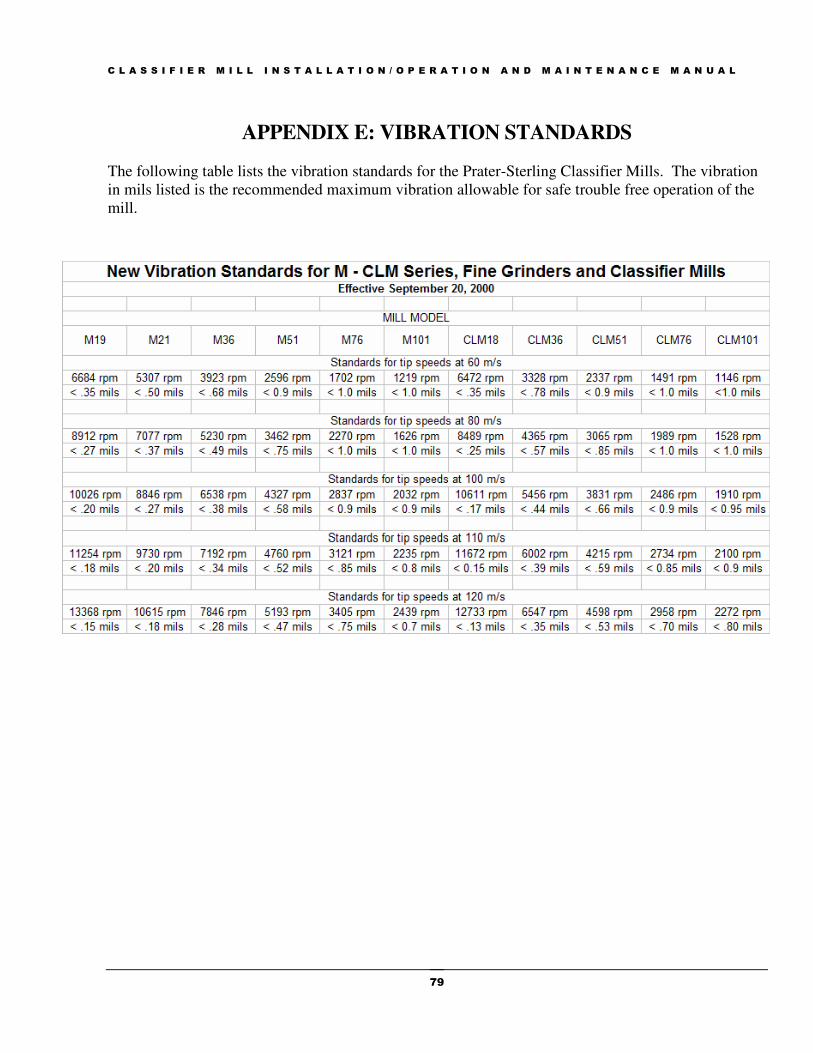
C L A S S I F I E R M I L L I N S T A L L A T I O N / O P E R A T I O N A N D M A I N T E N A N C E M A N U A L
79
APPENDIX E: VIBRATION STANDARDS The following table lists the vibration standards for the Prater-Sterling Classifier Mills. The vibration
in mils listed is the recommended maximum vibration allowable for safe trouble free operation of the
mill.

C L A S S I F I E R M I L L I N S T A L L A T I O N / O P E R A T I O N A N D M A I N T E N A N C E M A N U A L
80
APPENDIX F: PROTECTING THE CLASSIFIER MILL FROM
STATIC ELECTRICITY
Bearing Failures from Static Electricity
In many applications the processing of certain materials may generate static electricity inside the
Classifier Mill. Another source of static electricity is the friction that develops between the belts and
the drive sheaves. Without proper grounding of the mill rotor shaft this static may build to a point
where the voltage is great enough to overcome the resistance of the thin film of oil in the bearings.
Once this occurs the static buildup will discharge to ground typically through the mill housing causing
fusion craters in the bearings. Over a short period of time these craters increase in size and number
resulting in frosting, pitting, fluting, and eventually bearing failure. If there is no condition monitoring
installed on the mill this will likely lead to a catastrophic rotor failure if the mill is not stopped
immediately after the bearing failure
Rotor Blade Failures from Static Electricity
In some applications, particularly where the feed material is pneumatically conveyed into the mill,
static buildup may discharge inside the grinding chamber. This discharge may occur between the rotor
blades and the rotor disk, the rotor blades and the retaining rings, and the rotor blades and the screen
frame assembly. This may result in catastrophic rotor failure, which causes extensive and expensive
damage to the mill internal components. As in bearing failures, if there is no condition monitoring
installed on the mill this failure may result in a bearing failure as well.
Protecting the Classifier Mill from Static Electricity
Prater recommends that all Classifier Mills be equipped with a microfiber brush. Grounding brushes
provides a direct route to earth ground for any static buildup in the grinding chamber that allows the
charge to reach ground without going thru the bearings. Additionally this will protect the bearings
from any static generated by friction between the belts and the sheaves.
In any application where the feed material is pneumatically conveyed into the mill, the feed inlet must
incorporate a ground probe just prior to the entrance of the mill. The ground probe should be
connected to earth ground to allow any static buildup from conveying to discharge outside the mill.
Effective July 1, 2007 all Prater Classifier Mills will be equipped with a grounded bearing assembly and a lug on the frame for connection to earth ground.
NOTICE
C L A S S I F I E R M I L L I N S T A L L A T I O N / O P E R A T I O N A N D M A I N T E N A N C E M A N U A L
81
APPENDIX G: DUST COLLECTOR EXPLOSION VENTING
This guide applies to the design, location, installation, maintenance, and use of devices and systems
that vent the combustion gases and pressures resulting from a deflagration within an enclosure so that
structural and mechanical damage is minimized. A deflagration can result from the ignition of a
flammable gas, mist, or combustible dust. 1.1.2 This guide should be used as a companion document
to NFPA 69, Standard on Explosion Prevention Systems, which covers explosion prevention measures
and can be used in place of, or in conjunction with, NFPA 68. The choice of the most effective and
reliable means for explosion control should be based on an evaluation that includes the specific
conditions of the hazard and the objectives of protection. Venting of deflagrations only minimizes the
damage that results from combustion. 1.1.3. This guide does not apply to detonations, bulk
autoignition of gases, or unconfined deflagrations, such as open-air or vapor cloud explosions. 1.1.4*
This guide does not apply to devices that are designed to protect storage vessels against excess internal
pressure due to external fire exposure or to exposure to other heat sources. 1.1.5 This guide does not
apply to emergency vents for runaway exothermic reactions or self-decomposition reactions. 1.1.6
This guide does not apply to pressure relief devices on equipment such as oil-insulated transformers. It
also does not apply to pressure relief valves on tanks, pressure vessels, or domestic (residential)
appliances.
Dust Explosion Venting
NFPA 68, Venting of Deflagrations, applies to equipment or enclosures needing to withstand more
than 1.5 psig pressure. Most dust collectors need additional reinforcement for that capability. The
maximum pressure that will be reached during an explosion will always be greater than the pressure at
which the vent device releases. NFPA 68 calls for a pressure differential of at least 50 lbs./ft2 or 0.35
psi between the vent release pressure and the resistive pressure of the dust collector (enclosure). This
NFPA guide lists the following basic principles that are common to the venting of deflagrations. You
should become familiar with these principles so that you can correctly specify the conditions the dust
collector and explosion vent must satisfy.
1. The vent design must be sufficient to prevent deflagration pressure inside the dust collector
from exceeding two-thirds of the ultimate strength of the weakest part of the dust collector,
which must not fail. This criterion does anticipate that the dust collector may deform. So do
expect some downtime with the dust control system after an explosion.
2. Snow, ice, sticky materials or similar interferences must not affect dust vent explosion
operation.
3. Dust explosion vent closures must have a low mass per unit area to reduce opening time.
NFPA recommends a maximum total mass divided by the area of the vent opening of 2.5
lbs./ft2.
4. Dust explosion vent closures should not become projectiles as a result of their operation. The
closure should be properly restrained without affecting its function.

C L A S S I F I E R M I L L I N S T A L L A T I O N / O P E R A T I O N A N D M A I N T E N A N C E M A N U A L
82
5. Vent closures must not be affected by the process conditions, which it protects, or by
conditions on the non-process side.
6. Explosion vent closures must release at overpressures close to their design release pressures.
Magnetic or spring-loaded closures will satisfy this criterion when properly designed.
7. Explosion vent closures must reliably withstand fluctuating pressure differentials that are
below the design release pressure.
8. Dust explosion vent closures must be inspected and properly maintained in order to ensure
dependable operation. In some cases, this may mean replacing the vent closure at suitable time
intervals.
9. The supporting structure for the dust collector must be strong enough to withstand any reaction
forces developed as a result of operation of the dust explosion vent.
10. Industrial exhaust system ductwork connected to the dust collector may also require explosion
venting.

C L A S S I F I E R M I L L I N S T A L L A T I O N / O P E R A T I O N A N D M A I N T E N A N C E M A N U A L
83
APPENDIX H: ROTOR BLADE PLACEMENT PROCEDURES
CLM – 35/36 Rotor Blade Installation Procedures
Weigh all blades using a scale with 0.1 gram resolution and arrange them in ascending order by
weight. The lightest blade will be #1 and the heaviest #30. Thoroughly clean the blade slots and the
seat for the retaining ring before beginning the blade placement. Using the weight that was added to
the bare rotor as reference, install blade number one, into slot number one next to the weight.
Continue to install blades into corresponding slots on the diagram as shown. Write down weights of
blades on diagram for reference.
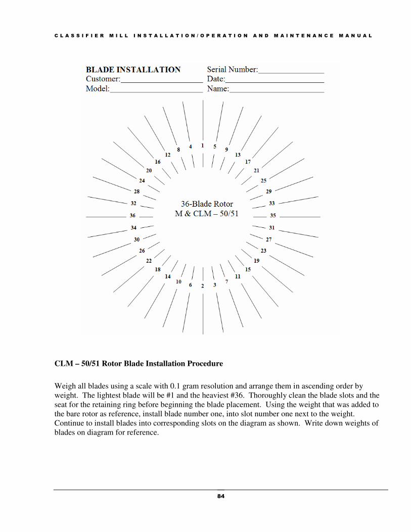
C L A S S I F I E R M I L L I N S T A L L A T I O N / O P E R A T I O N A N D M A I N T E N A N C E M A N U A L
84
CLM – 50/51 Rotor Blade Installation Procedure
Weigh all blades using a scale with 0.1 gram resolution and arrange them in ascending order by
weight. The lightest blade will be #1 and the heaviest #36. Thoroughly clean the blade slots and the
seat for the retaining ring before beginning the blade placement. Using the weight that was added to
the bare rotor as reference, install blade number one, into slot number one next to the weight.
Continue to install blades into corresponding slots on the diagram as shown. Write down weights of
blades on diagram for reference.

C L A S S I F I E R M I L L I N S T A L L A T I O N / O P E R A T I O N A N D M A I N T E N A N C E M A N U A L
85
CLM – 75/76 Rotor Blade Installation Procedures
Weigh all blades using a scale with 0.1 gram resolution and arrange them in ascending order by
weight. The lightest blade will be #1 and the heaviest #40. Thoroughly clean the blade slots and the
seat for the retaining ring before beginning the blade placement. Using the weight that was added to
the bare rotor as reference, install blade number one, into slot number one next to the weight.
Continue to install blades into corresponding slots on the diagram as shown. Write down weights of
blades on diagram for reference.

C L A S S I F I E R M I L L I N S T A L L A T I O N / O P E R A T I O N A N D M A I N T E N A N C E M A N U A L
86
CLM-100/101 Rotor Blade Installation Procedure
Weigh all blades using a scale with 0.1 gram resolution and arrange them in ascending order by
weight. The lightest blade will be #1 and the heaviest #48. Thoroughly clean the blade slots and the
seat for the retaining ring before beginning the blade placement. Using the weight that was added to
the bare rotor as reference, install blade number one, into slot number one next to the weight.
Continue to install blades into corresponding slots on the diagram as shown. Write down weights of
blades on diagram for reference.