classification and tracking of dynamic objects with …€¦ · classification and tracking of...
TRANSCRIPT
Classification and Tracking of Dynamic Objects with Multipl e Sensorsfor Autonomous Driving in Urban Environments
Michael Darms, Paul Rybski, Chris Urmson
Abstract— Future driver assistance systems are likely touse a multisensor approach with heterogeneous sensors fortracking dynamic objects around the vehicle. The quality andtype of data available for a data fusion algorithm dependsheavily on the sensors detecting an object. This article presentsa general framework which allows the use sensor specificadvantages while abstracting the specific details of a sensor.Different tracking models are used depending on the currentset of sensors detecting the object. A sensor independentalgorithm for classifying objects regarding their current andpast movement state is presented. The described architectureand algorithms have been successfully implemented in TartanRacing’s autonomous vehicle for the Urban Grand Challenge.Results are presented and discussed.
I. INTRODUCTION
Most of the existing commercial driver assistance systemswith environmental perception are designed for longitudinaltraffic in well structured environments (for example AdaptiveCruise Control [1]). Currently new driver assistance systemsare being developed which work in more complex envi-ronments and use a multisensor fusion approach to processsensor data [2]. Examples are systems for intersection assis-tance or systems that assist drivers in construction sites on ahighway.
One challenge that must be addressed is the distinctionof static and moving obstacles in these environments. Someadaptive cruise control systems for example are designed tonot react to objects which have not been detected movingby the system to avoid false reactions due to sensor artifacts(where artifacts are defined as erroneous detections or mis-interpretations). On the other hand future driver assistancesystems will be designed to work with static obstacleslike poles or guardrails, too. Analogous to moving obstacletracking [2], special algorithms exist to estimate the positionand shape of static obstacles. To reduce artifacts with thesealgorithms it is important to distinguish static from dynamicobstacles, too [4].
In well structured environments like on a highway sensorartifacts are well understood and a distinction of static and
This work would not have been possible without the dedicatedeffortsof the Tartan Racing team and the generous support of our sponsorsincluding General Motors, Caterpillar, and Continental. This work wasfurther supported by DARPA under contract HR0011-06-C-0142.
Passages about the model switching approach have been published ona local german conference ”Steuerung und Regelung von Fahrzeugen undMotoren”, 12./13. February 2008 in Baden-Baden [5].
M. Darms is with Continental Inc., Auburn Hills, MI, USA. Email:[email protected]
P. Rybski is with Carnegie Mellon University, Pittsburgh, PA, USA.Email: [email protected]
C. Urmson is with Carnegie Mellon University, Pittsburgh, PA, USA.Email: [email protected]
moving obstacles can be done reliably. In more complexenvironments like an urban setting new artifacts come intoplay. Here a multisensor approach can help to make themovement classification more robust using the availableredundancy.
On the other hand more sensors lead to an increasedcomplexity. Typical driver assistance systems today use asingle environmental sensor and a tracking model tied tothe characteristics of this sensor. When using heterogeneoussensors which are based on different sensor technologies thequality and type of the data now depends on the combinationof sensors detecting an object [5][6]. Besides that, differ-ent sensors produce different kinds of misinterpretationsofmeasurements, so called artifacts. These depend on sensorinternals like the detection mechanism and feature extractionalgorithms for example.
This article describes an architecture for sensor data fusionwhich allows to incorporate the information of differentsensors in a generalized way. All sensor specific algorithmsare encapsulated in sensor specific modules with a general-ized interface. This reduces the effort needed to extend thesystem with new sensors or sensor technologies. Two sensorindependent algorithms implemented in this architecture willbe described which address the topics described above:An adaptive model switching approach which deals withthe phenomenon of sensor dependent data quality, and amovement classification algorithm which robustly combinesthe information of different sensors to an overall movementclassification.
The architecture and algorithms have been successfullyimplemented in Tartan Racing’s autonomous vehicle for theUrban Challenge 2007 . Data from thirteen environmentalsensors with different detection modes has been fused intoa model of composite object hypotheses. The data was usedin a variety of applications including distance keeping, inter-section handling and parking. The environment consisted ofan urban road network with intersections, sharp curves andfree traffic in open parking lots.
II. M ULTISENSORSETUP
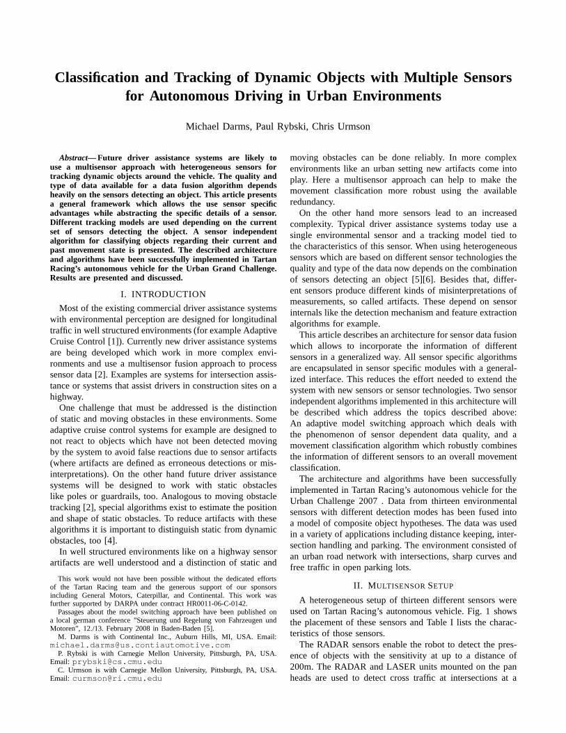
A heterogeneous setup of thirteen different sensors wereused on Tartan Racing’s autonomous vehicle. Fig. 1 showsthe placement of these sensors and Table I lists the charac-teristics of those sensors.
The RADAR sensors enable the robot to detect the pres-ence of objects with the sensitivity at up to a distance of200m. The RADAR and LASER units mounted on the panheads are used to detect cross traffic at intersections at a

Fig. 1. Sensor setup on Tartan Racing’s autonomous vehicle [5].
TABLE I
SENSORSCHARACTERISTICS[5]
Edge Target/2D coordinates, height
information target for validation
360°26.8°120mScanning Laser,
64 beams
Velodyne
HDL-64E
Edge Target/2D coordinates of
detection
240°3.2°200mScanning Laser,
4 level
IBEO
AlascaXT
Edge Target/2D coordinates ofdetection
180°0.25°80 mScanning Laser,
1 level
SICK
LMS291
2D coordinates of detection14°4°150mFixed Beam
Laser
Continental
ISF172
2D coordinates of detection/velocity56/184.3°60m/
200m
Scanning Radar
(near/far)
Continental
ARS300
Features used for trackingHoriz.Angle*
Vertic.
Angle*
Max.
Range*
Sensor TypeSensor
*according to specification
sufficient distance to merge safely with traffic moving atspeeds up to 30mph. The RADARs measure Doppler shiftwhich allows direct measure of velocity which is moreaccurate than having to estimate velocity from multiplesequential distance measurements like the LASER sensors.The features extracted from RADAR data are reported as aset of 2D position coordinates that reflect the center of theobject along with an associated velocity of that point. Thefixed beam LASER sensors only return a 2D point, no directvelocity measurement is possible.
The planar scanning LASER sensors return informationabout the (2D) shape and orientation of a vehicle in thenear range [8]. The shape is computed from the intersectionof the plane of the beam with the object. The returnedshape is used to estimate the yaw angle and yaw rate ofthe detected vehicle. Due to the fixed angular resolution ofthe scanning lasers, the shape information at long distances isnot good enough to perform yaw estimation with the requiredaccuracy. As with the RADAR sensors the data however isaccurate enough to associate the information to lanes on theroad.
The 3D LASER scanner is the only sensor on the robotthat provides information about the shape of the object inheight as well as width and length. However, the effectivedetection range of the sensor is not sufficient for autonomousdriving with merging and passing maneuvers in 30mphtraffic. Furthermore, the top of the vehicle occludes some ofthe laser’s field of view and as such the laser cannot detectobjects that are extremely close to the vehicle (including alarge blind spot in the rear).
For the Urban Challenge no one sensor or sensor modalitywas sufficient to provide enough information to track objects
around the vehicle. The multiple sensors provided completesensing coverage all around the vehicle and the combinationof RADARs and LIDARs allowed for long-range detectionof vehicles while still being able to estimate shape andorientation as the vehicle approaches the robot. The multiplesensors also provided redundancy in case of sensor failuresand artifacts.
III. M ODELING MOVING OBSTACLES
A. Tracking Model
Tracking algorithms like the Kalman filter use a model todescribe the dynamic properties of an object hypothesis [3].The detail of the tracking model is defined both by the needsof the application and the capabilities of the used sensors.
We propose an approach where the tracking model isswitched according to the available sensor information. Twomodels were sufficient for all application scenarios of theUrban Challenge and serve as an example in the followingpart of the article: a box model and a point model.
The box model uses a fixed widthw and lengthl > w
to represent the shape of a vehicle whereas the point modelhas no shape information. The box model uses the positionof the center of the boxx, y the yaw angleφ, raw angle rateφ, a velocityv, and an accelerationa as state variables. Thevelocity and acceleration are always in the direction of thelonger edge of lengthl. The state propagation equations arebased on a simple bicycle model [7] which couple thex andy coordinates via the yaw angle and yaw rate.
The point model is described by 2 coordinates in the 2Dplanex, y the corresponding velocitiesx, y and accelerationsx, y. A constant acceleration model is used for state propa-gation [3]. The noise parameters adapt with the length anddirection of the velocity vector(x, y). This again couples thex andy coordinates and—similar to the bicycle model—doesnot constrain the model to a predefined direction definedby the coordinate system. This way the model is usablefor tracking vehicles driving in an arbitrary and previouslyunknown direction.
B. Movement Classification
Some applications need reliable information if an objectis potentially moving (like a vehicle) or if it is a static object(like a pole or traffic cone). For an autonomous vehicle likein the Urban Challenge this information is needed for thebehavior algorithms of the system. These are responsiblefor the decisions of the vehicle, like safe driving throughan intersection (”Is this object a parked vehicle or waitingfor precedence?”). Driver assistance systems make use ofthis information, too. Examples are systems for intersectionassistance or collision avoidance algorithms.
To get this information a detailed scene understandingis necessary. Even if a classification algorithm classifies anobject as a vehicle, ambiguous cases exist such as if thevehicle is parked or just about to start moving.
As a simplification which was sufficient for the scenariosof the Urban Challenge, we propose an algorithm whichclassifies all object hypothesis into:

Sensor Layer
Fusion Layer
Measurement (Detection/Observation,
Alternative/New Proposals, Movement Observation)
Object Hypothesis & Prediction
Proposal Generation
Local Movement Classification
Association
Feature Extraction
Estimation
Best Model Selection
Global Movement Classification
Applications
Fig. 2. Sensor Fusion Architecture [4], [5].
• The current movement state: Moving and Not Moving• The past movement state: Observed Moving and Not
Observed Moving
The current movement state is set to moving once the objecttracking system decides that the object is not stopped. Thepast movement state is set to observed moving, once theobject hypothesis has significantly changed its position. Asimilar classification is used in current adaptive cruise controlimplementations, which only react to objects, that have beenobserved moving in the past.
IV. SYSTEM ARCHITECTURE FOROBJECT TRACKING
Fig. 2 shows the architecture of a sensor fusion systemthat implements the two approaches described in the previoussections (see also [5], [9]). It is divided into two layers, aSensor Layer and a Fusion Layer. For each sensor type (e.g.RADAR, scanning LASER, etc.) a specialized sensor layeris implemented. For each sensor an instance of its particularsensor layer runs on the system. This way all sensor typespecific operations are encapsulated in specialized modules.New sensor types can be added without changing existingsensor modules and the implementation of the fusion layer.This simplifies the extensibility of the system.
At the fusion layer all general functions for object trackingare performed. These include state estimation, best modelselection, and movement classification (Fig. 3). State estima-tion is done with a probabilistic estimator using a predictionand an update step [5]. The algorithms for best modelselection and the movement classification will be describedin the following sections.
The current set of best object hypothesis is provided tothe applications and is also fed back to the sensor layer. Tobe compatible with this decomposition the algorithms insidethe fusion layer must have the following properties:
• Be independent of sensor types.• Be independent of the number of sensors used in the
tracking system.• Be independent of the number of tracking models used
in the tracking system.
All information about how states are propagated is encap-sulated in the fusion layer, the state propagation equations
x
y
Edge Target extracted from
laser raw data
x
y
Edge Target extracted from
laser raw data
1
2
3
4
Fig. 3. Left: Possible Box Model interpretations of Edge Targets. Right:Snapshots of a vehicle driving perpendicular to the robot through anintersection. Edge Targets: Laser scanner features; Diamonds: Radar features[5].
are hidden to the sensor layer. An application specific fil-tering can be achieved this way [9], however this was notimplemented for the Urban Grand Challenge.
Each time a sensor has new raw data it requests aprediction of the current best set of object hypothesis atthe current measurement time and associates the raw datato these predicted object hypothesis [9]. For each extractedfeature a set of possible interpretations is created by usinga heuristic which takes the sensor specific characteristicsofthe raw data into account. Examples for these characteristicsare the resolution of the sensor, the noise level of distancemeasurements, the maximum angle under which an objectis detectable or a special treatment of the boundaries of thefield of view.
Fig. 3 (right) shows edge targets which are extracted fromthe raw data of the scanning lasers (a heuristic for the planarlasers is described in [8]). Edge target features are ”L”shaped features, which describe objects which either havetwo edges with a near 90 angle or objects where only oneedge is visible. Fig. 3 (left) shows possible interpretations ofedge targets as a box model. As there is a great deal of uncer-tainty in the edge target features all possible interpretationsare generated. If the data is not sufficient to be interpretedasa box model (e.g. at larger distances or because the raw datadoes not represent a vehicle) a point object interpretationisused instead.
Based on a sensor specific heuristic a measure for thecompatibility of the generated interpretations with the asso-ciated prediction is computed. Then it is checked if any of theinterpretations differs significantly from the current trackingmodel used on the fusion layer.
If this is not the case then the best interpretation will beused to generate an observation. An observation holds allinformation necessary for the update step of the estimationat the fusion layer. It encapsulates the measurement equationsand the information about the measurement noise. Analogousto the state propagation encapsulated in the fusion layer, allof the observation information is encapsulated in the sensorlayer. Thus the algorithm which updates the state estimate atthe fusion layer does not need to interpret the data from thesensor layer. This makes the fusion layer independent of thesensors modules implemented in the system.
If any of the interpretation differs significantly from the

prediction provided by the fusion layer the sensor initializesa new object hypothesis for each differing interpretation.Any of these new hypothesis can potentially replace thecurrent model hypothesis used on the fusion layer. A setof hypothesis is called proposal. A proposal can be providedin addition to an observation or - if there is no interpretationcompatible with the current best object hypothesis - withoutan observation. In this case the associated data is only calleda detection to reflect the fact that the sensor detected theobject, but cannot provide any meaningful information forthe state estimation. For features which cannot be associatedto any object hypothesis a sensor module provides an unasso-ciated proposal per extracted feature with an ordinal orderingof the quality of the contained new object hypotheses.
In the fusion layer the best tracking model is selectedbased on the proposals provided from the different sensorsand any other information available. The implementationused during the Urban Challenge uses information about roadshape to bias the selection of the best proposal in on roadscenarios. In parking lots scenarios the best proposal accord-ing to the ordinal ordering of the new object hypotheses isselected.
Depending on the sensor capabilities a sensor specificmovement classification algorithm is implemented inside thesensor layer. The result of the sensor internal classificationis a so called movement observation. This can be one outof three possibilities:movement confirmation, no movementconfirmation, no information available.
A movement confirmationtells the fusion layer that thesensor assumes that the associated object hypothesis iscurrently moving based on the sensor internal judgement.In our configuration the RADAR module could measure thevelocity via the Doppler shift. The movement of objects notmoving perpendicular to the RADAR measurement directioncan be detected reliably this way.
A no movement confirmationtells the fusion layer thatthe associated object hypothesis is currently not moving. Ascertain sensors can detect a movement only in a specificdirections (like the RADAR sensor described above) theinformation is passed in form of a so calledno movement vec-tor, which is a unit vector pointing in the direction in whichthe sensor detected no movement. A special case is a nullvector which can be used if based in the sensor informationthe object is not moving at all. This approach could be usedwith vehicle to vehicle communication available for example,however it was not used during the Urban Challenge.
Finally no information availabletells the fusion layer thatthe sensor module cannot provide any information regardingthe current movement state for the associated object.
V. M ODEL SELECTION ALGORITHM
A heuristic is used inside the fusion layer to determine thebest model for tracking [5]. It is only based on the proposalsand observations from sensors which currently detect orobserve a given object.
A sensorsupportsa model if by using only observationsfrom this particular sensor the model is observable in princi-
ple. For instance, the planar and 3D LASER sensors supportboth the box and the point model while the RADAR andfixed beam LASER sensors can only support the point model.
A sensorproposesa particular model if it provides anproposal with this model as an alternative to the modelcurrently in use by the fusion layer. The model may bedifferent in either the state vector (e.g. a different yaw anglefor a box model, for example); or it may be a differentmodel entirely (e.g. a point model instead of a box model).A sensor will propose an entirely different model if it cannotsupport the current model at all (e.g. a RADAR sensor willalways propose a point model, if the current model is a boxmodel) or if the sensor does not support the current modelbased on the internally computed quality measure for theinterpretation (e.g. a LASER sensor can propose a pointmodel if the detected vehicle is at a distance where yawcannot be estimated anymore).
A model iscurrently supportedby a sensor if the sensor iscurrently directly observing the object with the model (e.g.LASER sensor observes a box model) or if the sensor iscurrently proposing the model as an alternative (e.g LASERsensor proposes a box model while the point model is thecurrent model). Before a proposal can be considered by thefusion layer, the sensor must continually propose that modelfor a pre-defined number of consecutive cycles. This helps tomitigate rapid model switching in the case where the sensoris receiving noisy returns.
Algorithm 1 Model selection algorithm1: j = 0, modelPref[0...numberOfModels]= 02: for all possible modelsi = 1...numberOfModelsdo3: relSupport[i] ← numCurrentlySupportingSenors/numSupportingSensors4: if relSupport[i] >= minRelSupportthen5: modelPref[i] ← modelPref[j] + 16: j = i
7: end if8: end for9: maxModelPref← max(modelPref[])10: maxModelPrefIdx← max arg(modelPref[])11: if 0 == maxModelPrefthen12: do nothing (no decision is possible, keep the current best model)13: exit the algorithm14: else15: bestModel← model[maxModelPrefIdx]16: end if17: if bestModel==currentModelthen18: thresh← floor(numSupportingSensors∗thresholdReinit)19: if numProposingSensors> thresh then20: reinitialize model (model is OK but states need to be reinitialized)21: else22: do nothing (may be a false alarm)23: end if24: else25: change model to bestModel26: end if
In the current implementation the box model is the pre-ferred model above the point model and the system willattempt to use that model whenever possible due to theadditional information in conveys. Alg. 1 describes thedecision algorithm [5]. Lines 1-16 of the algorithm decidewhich model type has the highest support by the sensors. Byvarying the valueminRelSupportthe point at which modelsare switched can be adjusted. A higher value ensures that aswitch to model with a higher accuracy will be performed

only if there are enough sensors supporting it. In the TartanRacing system the number of supporting sensors increasesas the tracked vehicle gets closer to the robot. For example,at a range closer than 30m up to four sensors can support thebox model, which helps to suppress artifacts as shown in Fig4, right. Lines 17-26 of the algorithm determine if the modelneeds to be reinitialized. Here again a minimum number ofsensors is needed to support the request for a reinitialization.The floor function ensures that not all sensors need to agreeto a reinitialization unlessthresholdReinitis set to 1.
VI. M OVEMENT CLASSIFICATION
A. Moving vs. Not Moving
The following heuristic inside the fusion layer combinesthe movement observations from all sensors detecting anobject to determine the current movement state.
First how often an object has been confirmed movingis determined by polling all sensors. If the total numberis above a thresholdthmoving then the object is calledpotentially moving. As all sensors are counted the time that isnecessary to get to the resultpotentially movingis dependenton the number of sensors currently detecting the object.If only one sensor detects the objectthmoving consecutiveconfirmations are needed.
If the object is not classified aspotentially movingbasedon the movement confirmations a statistical test on thevelocity estimation is performed. It is checked if the hy-pothesisH0: ”Absolute velocity is smaller thanvmin.” canbe rejected. If this is the case, then the object is classifiedaspotentially moving.
The statistical test can always be performed as it is basedon the state variables only. This is the case for situationswhere none of the sensors has the capability to perform asensor based movement confirmation as described above. Inour system this was true for the LASER sensors as no sensorspecific algorithm was implemented. There may however beways, to exploit information included in the raw data todetect a movement.
To get robust results the significance levelα of the testand vmin can be tuned. With a highervmin and a lowerα the test becomes more conservative. Loweringα leadsto longer times until enough data is available to rejectH0,increasingvmin leads to less false positives at low speeds,however slow objects are not classified correctly. Hardwarewise the test can influenced by increasing the number ofsensors detecting an object or with a higher accuracy of asingle sensor.
If an object is classified aspotentially movinga crosscheck against the no movement vectors provided by thesensors is performed. For this the dot product between thenormalized current velocity estimate and the no movementvector is build and checked against a threshold. If the resultfrom any of the dot products reveals that the object is notmoving then the object is classified as not moving, otherwiseit is classified as moving.
If the cross check can be performed depends on the sensorsdetecting the object. In our system the cross check could only
Autonomous Vehicle
at T-Intersection
Tracked Vehicle
on Road
(Point Model)
Tracked Vehicle
(Box Model)
Fig. 4. The model is switched from point to box once the vehicle isdetected with the scanning LASER sensors [5].
be performed when at least one RADAR sensor detected theobject. In all other cases only the result of the statisticaltestcan be used to determine the movement state.
B. Observed Moving vs. Not Observed Moving
To determine if an object should be classified asobservedmoving the following heuristic works robustly. First thedistance traveled is estimated from the last time the objecthas been classified asnot observed movingis evaluated. Ifthis distance is above a threshold it is checked if the objectisclassified asmovingbased on the movement observations. Ifthis is true, then the object is classified asobserved moving.If it is not true then the object has to be classified asmovingfor a time periodtobm
min,1 to be classified asobserved moving.The mandatory check against the distance traveled in-
creased the robustness against short term artifacts, especiallyduring the initialization phase of the filters. It is possibleto not perform this check for objects which are confirmedmoving by the sensors alone, however this did not increasethe performance significantly, so that the more conservativeapproach makes sense.
Because of artifacts and noise every approach will leadto wrong classifications in certain cases. This implies thatthere has to be a way to revise the current decision regardingthe observed movingclassification. The following heuristictakes short term artifact into account. Theobserved movingdecision is only kept if the object is classified as moving fora time periodtobm
min,2 > tobmmin,1. Once this time period is over
the observed moving flag is kept fortobmmax > tobm
min,2. As aresult a wrongobserved movingclassification is kept for amaximum oftobm
max.
VII. RESULTS
Fig. 4 shows a vehicle driving up to an intersectionwith the autonomous vehicle waiting for precedence. At adistance of more than 150m only the pointed RADAR sensordetects the approaching vehicle—the point model is usedfor tracking. The adaptation of the noise with respect to thevelocity vector stabilizes velocity estimation in the directionof travel. As soon as the vehicle is close enough for the

a) b) c)
(a) (b) (c)
Fig. 5. (a) Edge Targets. The targets left and right to the road originatefrom bushes. (b) Object hypotheses. (c) Only object hypotheses with theobserved moving flag are shown.
LASER sensors to generate box model proposals the trackingmodel is changed. The RADAR sensors still provide accuratevelocity measurements which allow a precise estimationof the time gap for merging—the position measurementshowever are represented only with a very low weight in theobservation. Due to the information provided by the LASERsensors the yaw angle of the object can now be estimated.
In open parking lots the sensor configuration can generatea box model with sufficient accuracy to predict the movementof a tracked vehicle for up to three seconds based onestimated states only. This makes the robot able to drivein an open parking lot together with other vehicles—humanor robot driven.
The distinction of static and moving obstacles was akey concept of the perception system of Tartan Racing’sautonomous vehicle for the Urban Challenge 2007 [4]. Fig.5 (a) shows features extracted form LASER scanner data ona road which has dense bushes and a fence next to the roadboundaries. Fig. 5 (b) shows the according object hypothesisand Fig. 5 (c) only object hypothesis which are classified asobserved moving. Only the vehicle driving down the road isclassified asobserved moving.
In environments encountered during the Urban Challengethe approach allowed smooth autonomous driving. The con-figuration used on the robot however was a compromisebetween the delay to classify an object hypothesis as moving,the minimum classification velocity and the suppression offalse alarms. In areas like shown in Fig. 5 (a) not all falsealarms for moving obstacles could be suppressed. Additionalinformation about the location of obstacles relative to theroad was used to bias the decision and reduce the numberof false alarms to nearly zero.
VIII. CONCLUSIONS AND FUTURE WORK
In a data fusion system with heterogeneous sensors thesensors contribute different levels of information. To make
the system extensible and flexible for changes an architectureand algorithms have to be found which allow an abstractionof the sensors.
In this paper we proposed an architecture which en-capsulates all sensor specific algorithms in a sensor layerand sensor independent algorithms in a fusion layer. Thearchitecture allowed an efficient development of our obstacletracking system for the Urban Challenge.
For object tracking we proposed an adaptive model switch-ing approach, where the tracking model is selected based onthe available sensor information. The selection is based onvotes from sensors detecting the object and is independentof the underlying sensors and tracking models. The practicalrealization showed that the approach works robustly for acombination of RADAR and LASER sensors (fixed beamand scanning).
For classifying the movement state of detected dynamicobstacles an sensor independent algorithm has been pre-sented, which combines sensor specific movement observa-tions and a sensor independent hypothesis test into a robustclassification of the movement state. We showed results ofthe algorithm which allow smooth autonomous driving ofour robot.
The feature extraction algorithms used for the LASERsensors searched for ”L” shapes only. In areas with bushesartifacts caused by this approach can lead to false pos-itives regarding the movement classification. Future workwill include the development of more sophisticated featureextraction algorithms which are able to reject this data in anearly stage. The additional use of information about the roadalready showed very good results.
REFERENCES
[1] Winner, H.: Adaptive Cruise Control. In Jurgen, R. K. (Hrsg.):Automotive Electronics Handbook. 2. Auflage. New York, London:Mcgraw-Hill, 1999, 30.1-30.30.
[2] Bishop, R.: ”Intelligent Vehicle Technology and Trends”, Bosten,London: Artech House Publishers, 2005.
[3] Bar-Shalom, Y.; Li, X.-R.: ”Multitarget multisensor tracking - princi-ples and techniques”, YBS, 1995, ISBN 0964831201.
[4] Darms, M., Rybski, P., Urmson, C.: ”Vehicle Detection and Track-ing for the Urban Grand Challenge”, AAET - Automatisierungs-,Assistenz- und eingebettete Systeme fr Transportmittel, Symposium13./14. Feb 2008, Braunschweig, 2008.
[5] Darms, M., Rybski, P., Urmson, C.: ”An Adaptive Model SwitchingApproach for a Multisensor Tracking System used for AutonomousDriving in an Urban Environment”, in Steuerung und RegelungvonFahrzeugen und Motoren - AUTOREG 2008. VDI-Berichte, Dsseldorf:VDI-Verlag, 2008.
[6] Stker, D.: Heterogene Sensordatenfusion zur robusten Objektverfol-gung im automobilen Straenverkehr. Oldenburg, Univ., Diss. (OnlinePublication), 2004 URL: http://deposit.d-nb.de/cgi-bin/dokserv?idn=972494464i.
[7] Kaempchen, N. et al.:”IMM object tracking for high dynamic drivingmaneuvers.”, IEEE Intelligent Vehicles Symposium 2004, 825 - 830.
[8] MacLachlan R.: ”Tracking Moving Objects From a Moving VehicleUsing a Laser Scanner”, tech. report CMU-RI-TR-05-07, CarnegieMellon University, June, 2005.
[9] Darms, M.; Winner, H. [Modular System Architecture]: A modularsystem architecture for sensor data processing of ADAS applications.In Intelligent Vehicles Symposium, 2005. Proceedings. IEEE. LasVegas, USA, 6.-8. Juni 2005 2005, 729 734