classic combi ff 280 - free boiler manuals · the boiler is directed to the dhw calorifier, ......
TRANSCRIPT

Classic Combi FF 280Installation & ServicingWall Mounted, Fanned, Balanced Flue Gas Boilers
NOTE TO THE INSTALLER: LEAVE THESE INSTRUCTIONS ADJACENT TO THE GAS METER
Classic Combi G.C. Appliance No.FF 280 .............................47 415 08
Natural Gas Models Only
CAUTION.To avoid the possibility of injury during the installation and servicing of this appliance, care should be taken when handling edges of sheet components.

Classic Combi FF 280 - Installation2
INTRODUCTIONThe new Classic Combi FF280 is a cast iron, balanced flue,fanned gas boiler.
Central heating (CH) output is spot rated at 23.4 kW (80 000Btu/h) with on/off thermostatic control and is suitable for use withheating loads down to 4.4 kW (15 000 Btu/h).
Maximum instantaneous domestic hot water (DHW) output isalso 23.4kW (80 000 Btu/h).
The boiler is designed for use with fully pumped sealed watersystems but can also be connected to open water systems ifrequired.
The boiler casing is of white enamelled mild steel with aremovable controls pod. A drop-down door gives access to thecontrol box.
Note. This boiler can only be used on fully pumped systems.
The boiler is supplied fully assembled, with a domestic hot watercalorifier, diverter valve, circulating pump, pressure gauge,safety valve and CH expansion vessel (contained in a moduleon top of the boiler).
Fixed temperature CH and DHW controls are fitted and theboiler incorporates a DHW 'preheat' facility.
The module also includes a CH thermostatic valve and bypass.No external bypass is required.
The domestic hot water and central heating pipe connectionsmay be made at the top or bottom of the boiler as required.
The boiler is supplied with a standard flue kit suitable for rear orside outlet applications up to 600mm (23 1/2"). Optional extraextension ducts up to 3m (118"), rear or side outlet, areavailable.
Note. A Vertex Flue Kit with a side outlet may be used - see theVertex Flue Kit Installation Instructions for details.
OPERATIONDomestic Hot Water (DHW)With no call for either DHW or CH the boiler will periodically fireat low gas rate for a few seconds, in order to maintain the DHWcalorifier in a preheated condition.
Note. The DHW 'preheat' operates 24 hours a day unless anexternal programmer is fitted, when it can be timed.
When there is demand for DHW the boiler fires at full gas rate,the diverter valve remains de-energised and the full output fromthe boiler is directed to the DHW calorifier, providing a maximumDHW draw-off of 9.6 l/m (2.1 gpm) at 35° C. temperature rise.
At DHW draw-off rates below approximately 6 l/m (1.3 gpm) theboiler reduces to low gas rate when the DHW temperaturereaches about 60°C and maintains the low draw-offtemperature between 50°C and 75°C. When the demand forDHW is satisfied the 'preheat' cycle resumes, unless there is aCH demand, which takes priority.Central Heating (CH)When there is demand for CH, the boiler fires at full output, tosupply the demand. The CH circuit within the moduleincorporates a thermostatic valve which operates to maintain ahigh boiler temperature during periods of cold CH start-up,necessary for the instantaneous delivery of DHW , if there is ademand at this time. Water is not released to the system until atemperature of 60°C. is reached within the boiler.Refer also to 'Boiler Water Circuit Diagrams'.
GENERAL
CONTENTS
Air Supply ..................................................................... 7
Boiler Clearances ......................................................... 6
Boiler Exploded View ................................................. 46
Burner Exploded View .............................................. .47
Control Box Exploded View ..................................... .47
Electrical Connections .............................................. 25
Electrical Regulations ................................................. 8
Extension Ducts - Fitting ........................................... 21
External Control ......................................................... 27
Fault Finding .............................................................. 48
Flueing .......................................................................... 7Rear Installation ...................................................... 13Side Installation ...................................................... 17
Gas Safety (Installation & Use)Regulations, 1994 ........................................................ 5
Gas Supply ................................................................... 5
Health & Safety Document No 635 ............................. 5
Initial Lighting . .......................................................... 29
Installation .................................................................. 11
Mandatory Requirements ............................................ 5
Pump ........................................................................... 24
Servicing ..................................................................... 32
Short List of Parts ...................................................... 54
Spares Replacement .................................................. 35
Terminal Guards. .......................................................... 7
Thermostatic Radiator Valves. .................................... 8
Water Circuit Diagrams ............................................... 4
Water Connections .................................................... 24
Water Requirements .................................................... 7

Classic Combi FF 280 - Installation 3
Boiler size FF 280Gas supply connection Rc 1/2 (1/2" BSP/t )Inlet connection Domestic Hot Water 15mm compression unionOutlet connection Domestic Hot Water 15mm compression unionFlow connection Central Heating 22mm compression unionReturn connection Central Heating 22mm compression unionSafety valve drain pipe connection 15mm copper (female)Flue terminal diameter mm (in.) 100 (4)Maximum working pressure (sealed systems) bar (psi) 2.5 (36.3)Maximum static water head m (ft.) 25 (82)Minimum static water head - open water systems m (ft.) 1.5 (5.0)Maximum domestic hot water inlet pressure bar (psi) 10.0 (145.0)Minimum domestic hot water inlet pressure bar (psi) 0.9 (13.1)Electrical supply 230 V ~ 50 HzMaximum power consumption 160WFuse rating External; 3A Internal; 2A (F)Water content Central Heating litre (gal.) 4.65 (1.0)
Domestic Hot Water litre (gal.) 0.55 (0.12)Dry weight (total) kg (lb) 78.7 (173)Maximum installation weight kg (lb) Combi module - 11.4 (25.1)
Boiler module - 52.6 (116)Boiler casing size Height mm (in.) 1045 (41 1/4)
Width mm (in.) 380 (15.0)Depth mm (in.) Top water connections - 300 (11 3/4)
Bottom water connections - 345 (13 1/2)
Table 1 - General DataGENERAL
Note. Gas consumption is calculated using a calorific value of 38.7 MJ/m3 (1038 Btu/ft3)
Domestic Hot Water Maximum
Burner setting pressure (hot) mbar (in.w.g.) 16.0 (6.4)
DHW output kW (Btu/h) 23.4 (80 000)
DHW input kW (Btu/h) 29.3 (100 000)
Gas consumption (hot) l/s (ft3/h) 0.76 (96.3)
Domestic hot water flow rate at 35°C. temp. rise l/m (gpm) 9.6 (2.1)
Table 3 - Performance Data - Domestic Hot Water
Table 2 - Performance Data - Central Heating
Central Heating Maximum
Burner setting pressure (hot) mbar (in.w.g.) 16.0 (6.4)
Output kW (Btu/h) 23.4 (80 000)
Input kW (Btu/h) 29.3 (100 000)
Gas consumption (hot) l/s (ft3/h) 0.76 (96.3)

Classic Combi FF 280 - Installation4
1 BOILER WATER CIRCUIT DIAGRAMS
GENERAL

Classic Combi FF 280 - Installation 5
OPTIONAL EXTRA KITSA Programmer KitA 90° Flue Elbow KitExtension ducts up to 3 m (118").
GENERAL
GAS SAFETY (INSTALLATION AND USE)REGULATIONS, 1994.It is law that all gas appliances are installed by a CORGIregistered installer (identified by ) in accordance with theabove regulations. Failure to install appliances correctly couldlead to prosecution. It is in your own interest, and that of safety,to ensure the law is complied with.
The installation of the boiler MUST also be in accordance withthe latest I.E.E Wiring Regulations, local building regulations,bylaws of the local water authority, the Building Regulations andBuilding Standards (Scotland) and any relevant requirements ofthe local authority.
Detailed recommendations are contained in the following BritishStandard Codes of Practice:
BS.6891 Low pressure installation pipes.
BS.6798 Installation of gas fired hot water boilers of ratedinput not exceeding 60 kW.
BS.5449 Forced circulation hot water systems.
BS.5546 Installation of gas hot water supplies for domesticpurposes (2nd Family Gases).
BS.5440:1 Flues for gas appliances of rated input notexceeding 60 kW.
BS.5440:2 Ventilation for gas appliances of rated input notexceeding 60 kW.
BS.7593:1992 Treatment of water in domestic hot water centralheating systems
HEALTH & SAFETY DOCUMENT NO 635The Electricity at Work Regulations, 1989.
Manufacturer’s notes must NOT be taken in any way asoverriding statutory obligations.
IMPORTANT.This appliance is certificated by the British Standards Institutionfor safety and performance. It is, therefore, important that noexternal control devices, e.g. flue dampers, economisers etc.,are directly connected to this appliance - unless covered bythese Installation and Servicing Instructions or otherwiserecommended by Caradon Ideal Ltd. in writing.If in doubt please enquire.
Any direct connection of a control device not approved byCaradon Ideal Ltd., could invalidate the BSI Certification andthe normal appliance warranty. It could also infringe the GasSafety Regulations and the above regulations.
LOCATION OF BOILERThe boiler must be installed on a flat and vertical wall, capable ofadequately supporting the weight of the boiler and any ancillaryequipment.
The boiler may be fitted on a combustible wall. Insulationbetween the wall and the boiler is not necessary, unless requiredby the local authority. The boiler must not be fitted outside.
Timber Framed BuildingsIf the boiler is to be fitted in a timber framed building it should befitted in accordance with the British Gas publication 'Guide forGas Installations in Timber Frame Housing', reference DM2.
BathroomsThe boiler may be installed in any room or internal space,although particular attention is drawn to the requirements of thecurrent I.E.E. (BS. 7671) Wiring Regulations and, in Scotland,the electrical provisions of the building regulations applicable inScotland with respect to the installation of the boiler in a room orinternal space containing a bath or shower.
Where a room-sealed appliance is installed in a room containinga bath or shower then the appliance and any electrical switch orappliance control utilising mains electricity should be so situatedthat it cannot be touched by a person using the bath or shower.
Where installation will be in an unusual location specialprocedures may be necessary and BS.6798 gives detailedguidance on this aspect.
Compartment InstallationsA compartment used to enclose the boiler should be designedand constructed specially for this purpose.An existing cupboard or compartment may be used, providedthat it is modified for the purpose.
In both cases details of essential features of cupboard /compartment design, including airing cupboard installation, areto conform to the following:
BS. 6798.
The position selected for installation MUST allow adequatespace for servicing in front of the boiler and for aircirculation around the boiler - see section on 'Air Supply'.
For the minimum clearances required for safety andsubsequent service see the wall mounting template andFrame 2. In addition, sufficient space may be required toallow lifting access to the wall mounting plate.
GAS SUPPLYThe local gas supplier should be consulted, at the installationplanning stage, in order to establish the availability of anadequate supply of gas. An existing service pipe must NOT beused without prior consultation with the local gas supplier.
A gas meter can only be connected by the local gas supplier orby a local regional contractor.
An existing meter should be checked, preferably by the gassupplier, to ensure that the meter is adequate to deal with therate of gas supply required. A MINIMUM pressure of 20mbarMUST be available at the boiler inlet, with the boiler operating.
Installation pipes MUST be fitted in accordance with BS. 6891.Pipework from the meter to the boiler MUST be of an adequatesize.
The complete installation MUST be tested for gas soundnessand purged as described in the above code.

Classic Combi FF 280 - Installation6
GENERAL2 BOILER DIMENSIONS / SERVICES
Flue length Accessories Product no.
Up to 600 B pack 1 off 111 492
600 to 1800 B pack 1 off + D pack 1 off 111 492 +111 493
1800 to 3000 B pack 1 off + D pack 2 off 111 492 +111 493, 2 offAll dimensions in mm (in.)
It is MOST important that the boiler is installed in avertical position.
3 DETERMINING THE FLUE LENGTH
Dimension X: Wall thickness (top water connections)orX plus 45mm (bottom water connections)
Dimension Y: Wall thickness plus boiler spacing
IMPORTANT. The direction of the water connections, i.e. tothe top or bottom of the boiler, must be decided BEFOREdetermining the flue length and position.
FLUE KITSPack B: supplied as standard.
Pack D: optional extension kit for side flue or rear flue outlet.Refer to 'Flue Extension Ducts'
1. A maximum of 2 extension ducts (plus the standard flueduct) may be used together.
2. Flue extensions of greater than 1m (39") should besupported with the bracket provided. If the stand-offbrackets have been used it is necessary, in order to keepthe flue aligned, to use the spacer bracket with thesupport bracket.
Dimension Side Flue Rear FlueA 425mm 390mm
B 25mm 5mmflue side both sides40mm
non-flue side
Additional space willbe required forinstallation,depending upon siteconditions.
Side Flue onlyProvided that the fluehole is cut accurately,e.g. with a core drill,
The following minimum clearances must be maintained foroperation and servicing (see diagram).
BOILER CLEARANCES
the flue can be installed from inside the building, up to 610mm(24") but, with flue lengths greater than the width of the boiler, thespace in which the boiler is to be installed must be at least equalto the flue length plus the length of the terminal grille.
Installation from insideONLYIf a core boring tool is to beused inside the building thespace in which the boiler isto be installed must be atleast wide enough toaccommodate the tool.
All installationsOnce the boiler has beeninstalled, the sideclearances may be reducedto 5mm.
Front clearance; 450mm(17 3/4") from the front ofthe boiler casing. Minimumfront clearance when built into cupboard is 75mm (3")
2. DHW outlet3. Safety valve drain
4. CH return5. CH flow
LEGEND1. DHW inlet

Classic Combi FF 280 - Installation 7
AIR SUPPLYDetailed recommendations for air supply are given inBS.5440:2.The following notes are for general guidance:1. It is NOT necessary to have a purpose provided air vent in
the room or internal space in which the boiler is installed.2. If the boiler is to be installed in a cupboard or compartment,
permanent air vents are required (for cooling purposes) atboth high and low levels. The air vents must eithercommunicate with room/internal space or be direct to outsideair. The minimum effective areas of the permanent air ventsrequired in the cupboard/compartment are specified asfollows and are related to maximum rated heat input.
3. Both air vents MUST communicate with the same room orinternal space or MUST be on the same wall to outside air.
4. In siting the air vents care must be taken to avoid thefreezing of pipework.
Refer to Table 5 for details of air vent position and sizing.
GENERAL
FLUE INSTALLATIONThe flue must be installed in accordance with therecommendations of BS. 5440:1.
The following notes are intended for general guidance:
1. The boiler MUST be installed so that the terminal is exposedto external air.
2. It is important that the position of the terminal allows the freepassage of air across it at all times.
3. Minimum acceptable spacing from the terminal toobstructions and ventilation openings are specified inTable 4.
4. Where the lowest part of the terminal is fitted less than 2m(6'6") above a balcony, above ground or above a flat roof towhich people have access then the terminal MUST beprotected by a purpose designed guard. The minimumspacing in Table 4; Nos. 2, 3, 4, 5 and 6 would be 75mm inorder to allow a terminal guard to be fitted.
Terminals guards are available from:
Tower Flue Components Ltd.,Vale Rise, Tonbridge, Kent TN9 1TB
Telephone No. 01732 351 555
Ensure that the guard is fitted centrally.
5. Where the terminal is fitted within 1000mm (39 1/2") of aplastic or painted gutter or 500mm (19 1/2") of paintedeaves then an aluminium shield at least 1000mm (39 1/2")long should be fitted to the underside of the gutter orpainted surface.
6. The air inlet/products outlet duct and the terminal of theboiler MUST NOT be closer than 25mm (1") to combustiblematerial. Detailed recommendations on the protection ofcombustible material are given in BS.5440: Part 1.
7. Where it is essential that the terminal wall plate is fitted, i.e.wall thicknesses over 600mm (23 5/8") or with aninaccurately cut hole, the minimum spacing in Table 4, Nos.2,3, 5 and 6 would be 60mm in order to allow the terminalwall plate to be fitted.
IMPORTANTIt is absolutely ESSENTIAL to ensure, in practice, that productsof combustion discharging from the terminal cannot re-enter thebuilding or any other adjacent building through ventilators,windows, doors, other sources of natural air infiltration or forcedventilation/air conditioning.
If this should occur, the appliance MUST be turned OFFimmediately, labelled 'unsafe' and corrective action taken.
TERMINALThe terminal assembly can be adapted to accommodate variouswall thicknesses - refer to Frame 6 'Unpacking'.
Table 4 - Balanced flue terminal position
Terminal Position Minimum Spacing
1. Directly below or alongside anopenable window, air vent or otherventilation opening 300 mm (12")
2. Below guttering, drain pipes or soilpipes 25 mm ( 1")
3. Below eaves 25 mm ( 1")4. Below balconies or a car port roof 25 mm ( 1")5. From vertical drain pipes or soil pipes 25 mm ( 1")6. From internal or external corners 25 mm ( 1")7. Above adjacent ground, roof or
balcony level 300 mm (12")8. From a surface facing the terminal 600 mm (24")9. From a terminal facing a terminal 1200 mm (48")10. From an opening in a car port
(e.g. door or window) into dwelling 1200 mm (48")11. Vertically from a terminal on the
same wall 1500 mm (60")
12. Horizontally from a terminal on the wall 300 mm (12")
Table 5 - Air supply
Position of air vent Air from room/ Air directinternal space from outside
High level cm2 (in2) 264 (41) 132 (21)
Low level cm2 (in2) 264 (41) 132 (21)
WATER CIRCULATION SYSTEMThe boiler is designed for connection to sealed water centralheating systems but connection may be made to open watersystems, if required. The domestic hot water (DHW) calorifier isincorporated within the boiler casing and only requiresconnection to the mains water supply.

Classic Combi FF 280 - Installation8
Water connections maybe made at the top of, or to the bottomof the boiler.
IMPORTANT
Ensure that the mains water supply pressure is adequate toprovide the required DHW flow rate. Refer to Tables 1 and 3 onpage 3.
The central heating system should be in accordance with BS.6798 and, in addition, for smallbore and microbore systems,BS. 5449.
The domestic hot water system should be in accordance withthe relevant recommendations of BS. 5546.
Copper tubing to BS. 2871:1 is recommended for water-carrying pipework, and MUST be used for pipework carryingpotable water.
Ancillary pipework not forming part of the useful heating surfaceshould be lagged to prevent heat loss and any possible freezing- particularly where pipes run through roof spaces andventilated underfloor spaces.
IMPORTANTDraining taps MUST be located in accessible positions, whichpermit the draining of the whole system. They should be at least1/2" BSP nominal size and be in accordance with BS. 2879.
Maximum recommended system hydraulic losses are given inTable 6 below:
Table 6 - Water flow rate and pressure loss
System load kW 23.4 19.0 4.4(Btu/h) (80 000) (65 000) (15 000)
Water flow rate l/min 22.5 24.8 5(gal/h) (297) (327) (75)
Temperature °C 15 11 11differential (°F) (27) (20) (20)
Pressure mbar 157 118 391available for system (in. w.g.) (63) (47) (157)
GENERAL
THERMOSTATIC RADIATOR VALVESCaradon Ideal Ltd. recommend that heating systems utilisingfull thermostatic radiator valve control of temperature inindividual rooms should also be fitted with a room thermostatcontrolling the temperature in a space served by radiators notfitted with such a valve, as stated in BS. 5449.
When thermostatic radiator valves are used the space heatingtemperature control over a living / dining area or hallway havinga heating requirement of at least 10% of the boiler heat outputshould be achieved using a room thermostat, whilst other roomsare individually controlled by thermostatic radiator valves.However, if the system employs thermostatic radiator valves onall radiators or 2 port valves without end switches then a bypassmust be fitted to ensure a flow of water, should all valves be inthe closed position.
ELECTRICAL SUPPLYWiring external to the appliance MUST be in accordance withthe current I.E.E. (BS.7671) Wiring Regulations and any localregulations which apply.
The point of connection to the mains should be readilyaccessible and adjacent to the boiler, except that for bathroominstallations; the point of connection to the mains MUST besituated outside of the bathroom.
Note. Where a room sealed appliance is installed in a roomcontaining a bath or shower then the appliance and anyelectrical switch or appliance control utilising mains electricityshould be so situated that it cannot be touched by a personusing the bath or shower.

Classic Combi FF 280 - Installation 9
Safety valve setting bar 3.0Vessel charge pressure bar 0.5 to 0.75System pre-charge pressure bar None 1.0System volume (litres) Expansion vessel
v o l u m e (l i t r e s )25 1.6 1.850 3.1 3.775 4.7 5.5
100 6.3 7.4125 7.8 9.2150 9.4 11.0175 10.9 12.9190 11.9 14.0200 12.5 14.7250 15.6 18.4300 18.8 22.1
Multiplying factors forother system volumes 0.063 0.074
4 SYSTEM REQUIREMENTS - CENTRAL HEATING
Mains watersupply
Boiler
3. Mains Connection
There must be no direct connection to the mains water supplyor to the water storage tank supplying domestic water, eventhrough a non-return valve, without the approval of the localwater authority.
4. Filling
The system may be filled by one of the following methods:
a. Through a temporary hose connection from a draw-off tapsupplied from a service pipe under mains pressure. Wherethe mains pressure is excessive a pressure reducing valvemust be used to facilitate filling.
i. Thoroughly flush out the whole system with coldwater.
ii. Fill and vent the system until the pressure gaugeregisters 1.5 bar (21.5 psi) and examine for leaks.
iii. Check the operation of the safety valve by raising thewater pressure until the valve lifts. This should occurwithin 0.3 bar (4.3psi) of the pre-set lift pressure.
iv. Release water from the system until the minimumsystem design pressure is reached - 1.0bar (14.5 psi)if the system is to be pre-pressurised.
CH RETURN CH FLOW
stop valve test cock
Double check valve
Hosepipe(disconnectafter filling)
Hoseunion bib
tap
Notes.a. The method of filling, refilling, topping up or flushing sealed
primary hot water circuits from the mains via a temporary hoseconnection is only allowed if acceptable to the local waterauthority.
b. Antifreeze fluid, corrosion and scale inhibitor fluids suitable for usewith boilers having cast iron heat exchangers may be used in thecentral heating system. For further information contact:
Fernox Manufacturing Co. Ltd.,Britannic Works, Clavering, Essex. CB11 4QZ.Tel: 01799 550 811orGrace Service ChemicalsGrace Dearborn Ltd.,Widnes, Cheshire. WA8 8UD.Tel: 0151 424 5351
1. Generala. The installation must comply with the requirements of
BS.6891:1988 and BS.5449:1.b. The installation should be designed to work with flow
temperatures of up to 820C.c. All components of the system must be suitable for a
working pressure of 3 bar (45psi ) and temperature of1100C. Care should be taken in making all connections sothat the risk of leakage is minimised.The following components are incorporated within theappliance:• Circulating pump• Safety valve, with a non-adjustable pre-set lift
pressure of 3bar (45 psi)• Pressure gauge, covering a range of 0-6 bar.• 8-litre expansion vessel, with an initial charge
pressure of 0.75 bar.For further details refer to BS. 5449:1 and British Gaspublication 'Specifications for Domestic Central Heating andHot Water'.
2. Make-up WaterProvision must be made for replacing water lossfrom the system, either:
a. From a manually filled 'make-up' vessel with areadily visible water level.The vessel should be mounted at least 150mm (6")above the highest point of the system, and beconnected through a non-return valve to thesystem, fitted at least 150mm (6") below themake-up vessel on the return side of the domestichot water cylinder or radiators.
b. Where access to a make-up vessel would bedifficult by pre-pressurisation of the system.Refer to note 4 'Filling'. The maximum cold watercapacity of the system should not exceed 127litres if not pressurized. However, if the system isto be pressurized the efficiency of the expansionvessel will be reduced and a larger vessel (orsmaller system volume) may be necessary. If thecapacity of the vessel is not considered sufficientfor this, or for any other reason, an additionalvessel MUST be installed on the return to theboiler. Guidance on vessel sizing is given in thetable shown and also in BS.7074:1 andBS.5449:1.

Classic Combi FF 280 - Installation10
5 SYSTEM REQUIREMENTS - CENTRAL HEATING - continued
The following fittings shall form a permanent part of thesystem and shall be fitted in the order stated:
• A stop valve complying with the requirements ofBS. 1010:2 (the hose from the draw-off tap shall beconnected to this fitting).
• A test cock.• A double check valve of an approved type.
GENERAL
Boiler
CisternMainswatersupply
b. Through a cistern, used for no other purposes, via a ballvalve permanently connected directly to a service pipeand/or a cold water distributing pipe.The static head available from the cistern should beadequate to provide the desired initial system designpressure.
Note. The stop valve may remain open during normaloperation of the system if automatic water make-up isrequired.
5. The maximum recommended system hydraulic losses aregiven below:
System load kW 23.4 19.0 4.4(Btu/h) (80 000) (65 000) (15 000)
Water flow rate l/min 22.5 24.8 5.7(gal/h) (297) (327) (75)
Temperature °C 15 11 11differential (°F) (27) (20) (20)
Pressure mbar 157 118 391available for system (in. w.g.) (63) (47) (157)
6. Thermostatic radiator valves
Caradon Ideal Ltd., support the recommendations madeby leading manufacturers of domestic heating controls thatheating systems utilising full thermostatic radiator valvecontrol of temperature in individual rooms should also befitted with a room thermostat controlling the temperature ina space served by radiators not fitted with such a valve.Such an arrangement will provide for a more efficientcontrol of the environment and will also avoid thecontinuous running of the circulation pump duringprogrammed heating ON periods, saving electrical energy.It is therefore strongly recommended that, whenthermostatic radiator valves are used, the space heatingtemperature control over a living / dining area or a hallwayhaving a heating requirement of at least 10% of the boileroutput is achieved using a room thermostat, whilst otherrooms are individually controlled by thermostatic radiatorvalves.
7. Open vented systems
The Classic Combi FF280 is designed for use with sealedsystems but can also be connected to open ventedsystems if required.
Note. To comply with the relevant requirements ofBS.5449:1 and BS.6798 the positions of the cold feed andvent must be as shown.
DOMESTIC HOT WATER REQUIREMENTSThe Classic Combi FF280 is suitable for connection to mosttypes of washing machine and dish washing appliances.
When connecting to suitable showers ensure that:
• The cold inlet to the boiler is fitted with an approved anti-vacuum or syphon non-return valve.
• Hot and cold water supplies to the shower are of equalpressure.
IMPORTANT.
Provision must be made to accommodate the expansion ofDHW contained within the appliance if a non-return valve isfitted to the DHW inlet. Refer to Frame 4.
22mm open vent
Water level450mm (min.)
450mm (min.) abovehighest point in the
system
150mm(max.)
Boiler
Inverted cold feedconnection - 15mm
Heatingload
1500mm(min.)
CH RETURN CHFLOW
Non-return valve
Automaticair vent
stop valve

Classic Combi FF 280 - Installation 11
Pack A Contents
Combi module
Boiler
Pack A1
INSTALLATION
The appliance is supplied as 2 separate modules (i.e. boiler module and Combi module) together with wall mounting plate(Pack A1) in one Pack A.
Also supplied is a standard flue assembly for lengths up to 600mm (23 1/2"), rear or side flue outlet, in Pack B.
Optional extras, if ordered (Extension Duct Kit D, Vertex Flue Kit G, Roof Flue Kit H and 90° Flue Elbow Kit) are available inseparate boxes.
Unpack and check the contents.
6 UNPACKING
Pack B Contents:
Flue cutting support (cardboard) - 1 off
Terminal wall plate - 1 off
Terminal grille assembly - 1 off
Polyurethane foam seal 400 lg - 1 off
No. 8 x 8 lg. Pozi pan screw hd. screws - 3 off
Pack A1 Contents(contained within Pack A)
Installation & Servicing InstructionsUser's InstructionsHardware Pack (listed below)Wall mounting templateWall mounting plateStand-off brackets - 2 offSide outlet terminal mounting plate
Hardware Pack Contents
No.14 x 50mm wood screws - 8 off(for wall mounting plate)
No.10 x 50mm wood screws - 8 off(for side outlet plate and terminalwall plate)
Wall plugs - 16 off
M6 nuts - 8 off(for stand-off brackets)
M6 screws - 8 off(for stand-off brackets)
M6 washers - 8 off(for stand-off brackets)
Sealing plate - 1 off(for back panel)
M8 x 12mm screw - 1 off(for sealing plate)
M8 washer - 1 off(for sealing plate)
22mm compression elbow - 1 off(for boiler / combi RETURN)
22mm brass elbow - 1 off(for boiler / combi FLOW)
Plastic elbow extractor - 1 off
7/8" sealing washers - 2 off(for CH flow and return)
3/4" sealing washer - 1 off
1/2" sealing washers - 3 off(for DHW inlet & outlet and CH expansion vessel)
2 1/2" pozi-screw - 1 off(for Combi module cover)
Rubber gasket and screw - 1 off(bypass valve)
Terminal strip cover - 1 off
M5 washer - 1 off
M5 extended nut - 1 off
Flue extension tube - 1 off
M5 wing nut - 3 off
IEC mains plug
Boiler sealing plate
INS
TA
LL
AT
ION
Flue terminal Terminal wall plate

Classic Combi FF 280 - Installation12
INSTALLATION7 PACKAGING AND CASING REMOVAL
INS
TA
LL
AT
ION
1. Unpack the boiler.
2. Remove the casing as follows and place to one side toavoid damage:
a. Release controls pod fixing screws (a) 3 full turns only.Remove the pod by pulling it forward to disengage fromthe keyhole slots.
b. Undo the 4 screws (b) retaining thecasing to the back panel.
c. Remove the casing in the direction of thearrows.
3. Remove the boiler from its packaging base.The boiler may now be stood upright on itscontrols support protection frame to easehandling and installation.
4. Unpack the flue assembly / extension fluebox(es).
(a) Controls pod fixing screws, 2 off
(b) Casing retaining screws, 4 off
Packing base
Controls pod casing

Classic Combi FF 280 - Installation 13
Note. If theterminal is to besited within 25-40mm of a corneror vertical pipe(refer to Table 4)then the holeMUST beaccurately cut andthe rubberweather sealtrimmed aroundthe grooveprovided.The terminal wallplate need not befitted.
INSTALLATION REAR FLUE OUTLET ONLY8 FLUE ASSEMBLY - Exploded View
10 PREPARING THE WALLIMPORTANT.Ensure that, during the cutting operation, masonry falling outsideof the building does not cause damage or personal injury.
1. Cut the flue hole preferably with a 125mm (5") core boringtool, ensuring that the hole is square to the wall. If the holehas been quite accurately cut with a drill, then making goodthe wall faces is not essential as seals are provided at bothends of the flue. However, both wall faces immediately aroundthe cut hole should be flat; make good if necessary. For lessaccurate holes make good to approximately 125mm (5")diameter at the 2 wall faces.
2. Drill 9 holes for the wall mounting plate with an 8mm (5/16")masonry drill.
3. Insert the plastic plugs provided.
1. An optional flueduct extensionkit is requiredfor wallthicknessesgreater than600mm (23 1/2")Refer to Frame36.
9 WALL MOUNTING TEMPLATE
Note. The template shows the positions for the fixing holesand the flue hole centres for standard installation. Caremust be taken to ensure the correct holes are drilled.
LEGEND
1. Terminal.2. Weather seal.3. Flue assembly.4. Boiler sealing plate.5. Flue extension tube.
RE
AR
F
LU
E O
UT
LE
T
Note. Check all of the holepositions BEFORE drilling
1. Discard both sections B of the template.
2. Tape the template into the selected position.
3. Ensure squareness by hanging a plumb line as shown.
4. Mark onto the wall (if required) the following:
a. The 8 wall mounting plate screw positions and thelower fixing screw positions.
b. The position of the flue duct.
Note. Mark the centre of the flue hole as well as thecircumference.
5. Remove the template from the wall.

Classic Combi FF 280 - Installation14
11 CUTTING THE FLUE - wall thicknesses of 114 to 600mmINSTALLATION
14 FITTING THE FLUE ASSEMBLY1. Insert the flue extension tube into the flue assembly.
2. Insert the flue assembly through the hole far enough toallow the rubber seal to unfold completely and form anadequate seal on the outside wall.
3. Ensure the notch is at the top - this will aid the location ofthe studs into the boiler back panel.
12 FITTING THE BOILER SEALING RINGTO THE FLUE
2. Drill 3 holes 3.2mm (1/8") dia. through the outer flue duct andboiler sealing ring. Do NOT drill the inner flue duct.
3. Insert the self tapping screws,provided, in order to fix the boilersealing ring in position.
4. Stick the self adhesive foamstrip, provided in the hardwarepack, onto the flue immediatelybehind the boiler sealing ring.
1. Fit the boiler sealing ring insidethe outer flue duct. Ensure theboiler sealing ring is fullyengaged.Ensure the notch aligns withthe groove on the outer flueduct. This ensures correctalignment of the flue terminal.
1. Engage the plate(or plate andstand-offbrackets) on thetop fixing screws.
2. Locate six No.14x 2" screws in thelower fixing holesand drive homeall screws.
3. Check with aspirit level thatthe plate isvertical.
15 WALL MOUNTING PLATE
RE
AR
F
LU
E O
UT
LE
T
13 FITTING THE STAND-OFF BRACKETS
screws MUST be fitted in the top holes (marked with the symbol) with the shakeproof washers positioned under the screwheads.
1. Measure and note the wall thickness X.
2. Mark the wall thickness onto the flue.
3. To ensure the tube is cut square, mark the flue all theway round.
4. Cut to length X, using the cardboard ring for support.
5. Remove the cardboard ring and remove any burrs.
Note.If the stand-off brackets are used it is essential that 45mmis added to the measured wall thickness when marking theflue, to allow for the thickness of the brackets.
Installations with bottom water connectionsSecure the 2 stand-offbrackets to the wallmounting plate, using theeight M6 nuts, screws andshakeproof washersprovided so that the plate islocated BEHIND the frontreturns of the brackets, asshown.
Note. If the clearancesabove and below the boilerare less than the length ofthe pipes to be fitted behindthe wall mounting plate, thenrefer to Frame 16.
IMPORTANT. To ensureearth continuity, securing

Classic Combi FF 280 - Installation 15
2. Extend the pipes down the wall, as shown, ensuringthat:
a. They terminate at least 50mm (2") below the bottomof the wall mounting plate.
b. The CH flow and return pipes are vented to aidfilling.
Note. If the clearances above and below the boiler are less than the length of the pipes it will be necessary to position the piperuns behind the wall mounting plate BEFORE the plate is screwed to the wall.
FOR BOTH TOP AND BOTTOM WATER CONNECTIONS
If required, connection to the system pipework may now be made BEFORE the boiler is mounted on the wall.
PROCEED TO FRAME 42
INSTALLATION
17 PRE-WIRING
The mains supply and other external wiring may now be made, if required, BEFORE the boiler and Combimodules are mounted on the wall - refer to Frames 46 to 49.
RE
AR
&
S
ID
E F
LU
E O
UT
LE
T
IMPORTANT.
For installations with bottom water connections only; thefollowing pipe runs must be made before the boiler is mountedon the wall.
1. Make the connections to the fittings on top of the wallmounting plate, as shown.
Note. For installations with a minimum top clearance of100mm (4") the following fittings should be used.
• 22mm vented elbow (e.g. NIBCO)• 22mm M & F elbow (e.g. ENDEX)
16 PRE-PIPING

Classic Combi FF 280 - Installation16
INSTALLATION18 MOUNTING THE BOILER
19 CONNECTING THE FLUE TO THE BOILER
1. Pull the flue through the wall mounting plate and locatethe 3 studs in the holes in the back panel.
2. Secure the flue to the boiler using the three M5 wing nutsprovided.
3. Pull the flue extension tube and engage onto the fan,locate and secure with the M4 screw attached to the fan.
4. If a terminal wall plate is to be fitted proceed to Frame 34.
Note.
The sealing plate studs will locate in the back panel one wayonly. This will ensure that the terminal grille is correctlyaligned.
The boiler mounts ontothe wall plate hooks andis retained by the centralM8 screw, plain washerand large rectangularplate.
Note. Have ready to hand the M8 screw,plain washer and rectangular plate suppliedin the hardware pack.
1. Lift the boiler onto the wall mountingplate hooks as shown.
DO NOT USE THE BURNER /CONTROLS ASSEMBLY FOR LIFTING
IMPORTANT.
The boiler module MUST be positionedCENTRALLY on the wall mounting plate.Refer to the index mark on the backpanel.
2. Fit the M8 screw, washer and rectangularplate to retain the boiler.
Note.
Before fully tightening the M8 screw, checkthe boiler alignment using a spirit level, andadjust as necessary with the jacking screw -refer to Frame 3.
DO NOT USE THE BURNER / CONTROLS ASSEMBLY FOR LIFTING
APPLIANCES FITTED WITH A REAR OUTLET FLUE: PROCEED DIRECTLY TO FRAME 38
RE
AR
F
LU
E O
UT
LE
T

Classic Combi FF 280 - Installation 17
INSTALLATION SIDE FLUE OUTLET ONLY
20 FLUE ASSEMBLY - Exploded ViewFor wall thickness 114mm to 600mm
1. An optional flue ductextension kit is required forlengths (distance from theoutside wall to the relevantside of the boiler casing)greater than 600mm (23 1/2")Refer to Frame 3 .
LEGEND1. Terminal2. Weather seal3. Flue assembly4. Boiler sealing plate5. Flue extension tube
21 WALL MOUNTING TEMPLATENote. The template shows the positions for the fixing holes and the flue hole centresfor standard installation.
Installations with top water connections only:Tear off and discard the shaded portion of template B (refer to Frame 6)Care MUST be taken to ensure the correct holes are drilled.1. Separate the templates.2. Tape both templates into the selected position, locating template B through an
extended centre line, as shown.3. Ensure squareness by hanging a plumb line as shown.4. Mark onto the wall the following:
a. The wall mounting plate screw positions (choose one from each group).b. The 4 screw positions for the side outlet plate.c. The position of the flue duct hole. (Ensure that the correct centre is marked,
depending upon whether the brackets are used or not)Note. Mark the centre of the hole as well as the circumference.d. The side of the casing nearest the flue outlet.
SID
E F
LU
E O
UT
LE
T
5. Remove both templates from the wall.
22 PREPARING THE WALLIMPORTANT. Ensure that, during the cutting operation, masonry fallingoutside of the building does not cause damage or personal injury.
1. Cut the flue hole preferably with a 125mm (5") core boring tool, ensuringthat the hole is square to the wall. If the hole has been accurately cut witha drill then making good the wall faces is not essential as seals areprovided at both ends of the flue. However, both wall faces immediatelyaround the cut hole should be flat; make good if necessary. For lessaccurate holes make good to approximately 125mm (5") diameter at the 2wall faces.
2. Drill 8 holes with an 8mm (5/16") masonry drill and insert the plastic plugsprovided, for the side mounting plate and the wall mounting plate.
3. Drill 4 holes with a 7mm (9/32") masonry drill and insert the plastic plugsprovided for the side mounting plate.
Note. If the terminal is to be sited within 25-40mm of a corner or vertical pipe (refer toTable 4) then the hole MUST be accurately cut and the rubber weather seal trimmedaround the groove provided. The terminal wall plate need not be fitted.
Extended centre line
Terminal mounting plate screw and flue duct hole positions

Classic Combi FF 280 - Installation18
INSTALLATION
Flue assembly
26 FITTING THE FLUE ASSEMBLY
1. Insert the flue assembly through the hole far enough toallow the rubber seal to unfold completely and form anadequate seal on the outside wall. This will also ensurethe correct alignment of the flue terminal.
2. Ensure the notch is at the top. This will aid the location ofthe studs into the boiler back panel.
25 FITTING THE BOILER SEALING RINGTO THE FLUE
1. Fit the boiler sealing ring inside the outer flue duct.Ensure the boiler sealing ring is fully engaged.Ensure the notch aligns with the groove on the outer flueduct. This ensures correct alignment of the flue terminal.
2. Drill 3 holes 3.2mm (1/8") dia. through the outer flue ductand boiler sealing ring. Do not drill the inner flueduct.
3. Insert the self tapping screws, provided, in order to fix theboiler sealing ring in position.
24 FITTING THE FOAM SEAL
1. To determine the position for the foam seal, measure thewall thickness and mark it onto the flue, measuring fromthe groove near the terminal.
2. Wrap the self adhesive foam strip round the flue,ensuring that the foam is on the terminal side of the line.This seals the gap between the flue and the wall.
23 CUTTING THE FLUEFor flue lengths 114 to 600mm ONLY1. Measure the flue length required (i.e. the distance from
the side of the boiler to the outside face of the wall) -refer to Frame 3.
2. Mark the flue length required on to the flue, measuringfrom the groove near the terminal.
3. To ensure the tube is cut square, mark the flue all theway round.
4. Insert the cardboard duct ring for support and cut tolength.
5. Remove cardboard duct ring and remove any burrs.
For flue lengths greater than 600mm, refer toFrames 36 and 37- Flue extension ducts.
SID
E
FL
UE
OU
TLE
T

Classic Combi FF 280 - Installation 19
INSTALLATION
30 PRE-PIPING 31 PRE-WIRING
29 FITTING THE SIDE OUTLET PLATESNote. If the boiler is fitted closer than 25mm to the side wallthe side outletplate must befitted now.
1. Split the sideoutlet plateinto 2 downthe split line.
2. Fit the 2halves of theside outletplate to thewall,ensuring thatthey arebehind theboilersealing ring.
28 WALL MOUNTING PLATE1. Locate two No.14 x
2" screws in thewall mounting platetop fixing holes andscrew home towithin 6mm (1/4")of the wall surface.
2. Engage the plate(or plate and stand-off brackets) on thescrews.
3. Locate six No.14 x2" screws in thelower fixing holesand drive home all8 screws.
4. Check with a spiritlevel that the plateis vertical.
SID
E F
LU
E O
UT
LE
T
Secure the 2 stand-off brackets to the wall mounting plate,using the eight M6 nuts, screws and shakeproof washersprovided, so that the plate is located BEHIND the front returnsof the brackets, as shown.
Note.If the clearances above and below the boiler are less than thelength of the pipes to be fitted behind the wall mounting platethen refer to Frame 16.
IMPORTANT.
To ensure earth continuity, securing screws MUST be fitted inthe top holes (marked with the symbol) with the shakeproofwashers positioned under the screw heads.
Installations with bottom water connections only
27 FITTING THE STAND-OFF BRACKETS
IMPORTANT.
For installations with bottom water connections only
The pipe runs shown in Frame 16 must be made before theboiler is mounted on the wall.
For installations with both top and bottom water connections
If required, connection to the system pipework may now bemade before the boiler is mounted on the wall - proceed to'Water Connections', Frame 42.
The mains supply and other external wiring may now bemade, if required, before the boiler and Combi modulesare mounted on the wall.
Refer to Frames 46 to 49.

Classic Combi FF 280 - Installation20
INSTALLATION32 MOUNTING THE BOILER MODULE Note. Have ready to hand the M8 screw, plain washer
and rectangular plate supplied in the hardware pack.
1. Lift the boiler onto the wall mounting plate hooks asshown.
DO NOT USE THE BURNER / CONTROLS ASSEMBLYFOR LIFTING
IMPORTANT.
The boiler module MUST be positioned CENTRALLY onthe wall mounting plate. Refer to the index mark on theback panel
2. Fit the M8 screw, plain washer and rectangular plate toretain the boiler.
Note.Before fully tightening the M8 screw, check the boileralignment using a spirit level, and adjust as necessarywith the jacking screw - refer to Frame 3.
DO NOT USE THE BURNER / CONTROLS ASSEMBLY FOR LIFTING
The boiler mountsonto the wall platehooks and isretained by thecentral M8 screw,plain washer andlarge rectangularplate.
Terminal mounting plateThe air duct spigot engagesin the hole in the side panel.
33 CONNECTING THE FLUE TO THE BOILER
1. Pull the flue through the side outlet plate andlocate the 3 studs in the hole in the side ofthe boiler.
2. Secure the flue to the boiler using the threeM5 nuts, provided.
3. Insert the flue extension tube into the flue.
4. First remove the underside screw which isnot required then fit the 900 flue elbow,supplied with the boiler, onto the fan in thedirection required. Secure in position with thescrew.
5. Pull the flue extension tube and engage ontothe fan elbow and secure with the screw.
Note.The sealing plate studs will locate in the backpanel one way only. This will ensure that theterminal grille is correctly aligned.
SID
E F
LU
E O
UT
LE
T
Wall mounting plate

Classic Combi FF 280 - Installation 21
INSTALLATION
SID
E F
LU
E O
UT
LE
TGeneral arrangement
Note. Side flue shown.
1. A maximum of 2 extension ducts (plus the standard flueduct) may be used together.
2. Flue extensions of greater length than 1m (39") should besupported with the bracket provided. If the stand-offbrackets have been used it is necessary, in order to keepthe flue aligned, to use the spacer bracket with the supportbracket.
Flue length Accessories Product No.
Up to 600 B Pack 1 off see Frame 3
600 to 1800 B Pack 1 off + D Pack, 1 off see Frame 3
1800 to 3000 B Pack 1 off + D Pack, 2 off see Frame 3
Use a maximum of two extension ducts only
36 FLUE EXTENSION DUCTS - continued
35 FLUE EXTENSION DUCTS - For flue lengths greater than 600mm
34 TERMINAL WALL PLATE
This plate allows neat concealment and full compression of therubber seal. Its use is not essential if the flue hole and flue ductshave been accurately cut and the outside wall face is flat.
1. Position the terminal wall plate over the terminal.
2. Drill 4 fixing holes with an 7mm (9/32") masonry drill.
3. Insert the 4 plastic plugs provided.
4. Secure the plate with 4 of the No.10 x 2" screws provided.
Note.If the terminal is less than 2m (6' 6") above ground level, anapproved terminal guard should be fitted. Refer to the contentslist on Page 2.
PACK D Flue Extension Duct Kit contents
Flue length
Extension duct
Flue connector
Standard flue
Terminal grille
Boiler
Extension tube
Wall plug
No. 8 x 1/4" self tapping screws - 14 off
No. 10 x 3" wood screw -1off
Support bracket
Extension duct1.2m (42") long
Flue connectors - 2 off
Classic Combi FF 280 - Installation22
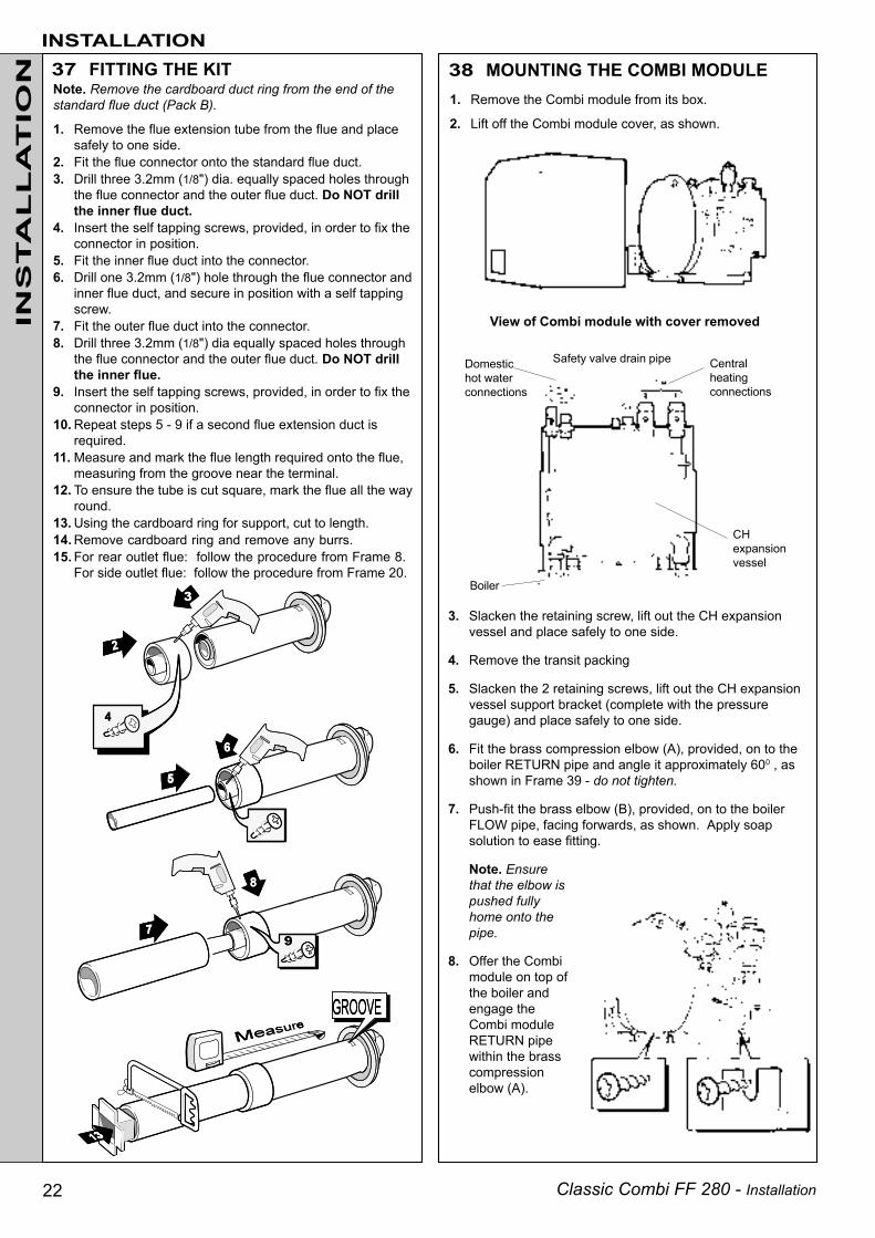
Note. Remove the cardboard duct ring from the end of thestandard flue duct (Pack B).
1. Remove the flue extension tube from the flue and placesafely to one side.
2. Fit the flue connector onto the standard flue duct.3. Drill three 3.2mm (1/8") dia. equally spaced holes through
the flue connector and the outer flue duct. Do NOT drillthe inner flue duct.
4. Insert the self tapping screws, provided, in order to fix theconnector in position.
5. Fit the inner flue duct into the connector.6. Drill one 3.2mm (1/8") hole through the flue connector and
inner flue duct, and secure in position with a self tappingscrew.
7. Fit the outer flue duct into the connector.8. Drill three 3.2mm (1/8") dia equally spaced holes through
the flue connector and the outer flue duct. Do NOT drillthe inner flue.
9. Insert the self tapping screws, provided, in order to fix theconnector in position.
10. Repeat steps 5 - 9 if a second flue extension duct isrequired.
11. Measure and mark the flue length required onto the flue,measuring from the groove near the terminal.
12. To ensure the tube is cut square, mark the flue all the wayround.
13. Using the cardboard ring for support, cut to length.14. Remove cardboard ring and remove any burrs.15. For rear outlet flue: follow the procedure from Frame 8.
For side outlet flue: follow the procedure from Frame 20.
Safety valve drain pipe Centralheatingconnections
Domestichot waterconnections
Boiler
CHexpansionvessel
3. Slacken the retaining screw, lift out the CH expansionvessel and place safely to one side.
4. Remove the transit packing
5. Slacken the 2 retaining screws, lift out the CH expansionvessel support bracket (complete with the pressuregauge) and place safely to one side.
6. Fit the brass compression elbow (A), provided, on to theboiler RETURN pipe and angle it approximately 600 , asshown in Frame 39 - do not tighten.
7. Push-fit the brass elbow (B), provided, on to the boilerFLOW pipe, facing forwards, as shown. Apply soapsolution to ease fitting.
Note. Ensurethat the elbow ispushed fullyhome onto thepipe.
8. Offer the Combimodule on top ofthe boiler andengage theCombi moduleRETURN pipewithin the brasscompressionelbow (A).
INSTALLATIONIN
STA
LL
AT
ION
1. Remove the Combi module from its box.
2. Lift off the Combi module cover, as shown.
View of Combi module with cover removed
37 FITTING THE KIT 38 MOUNTING THE COMBI MODULE

Classic Combi FF 280 - Installation 23
9. Swing the Combi module intoposition, as shown, and snap theCombi module FLOW pipe intothe brass elbow (B), ensuringthat it is pushed fully home to theindex mark on the Combi moduleflow pipe.
Note. Should it be necessary torealign the brass push-fit elbowon the boiler flow pipe elbow, thiscan be done using the plasticextractor supplied in thehardware pack.
DO NOT TIGHTEN THE BRASSCOMPRESSION ELBOW UNIONS
It may be found necessary to adjust the position of the pressuregauge in order for it to locate centrally in the aperture provided in themodule casing. This can be eased by checking the dimension fromthe bottom of the pressure gauge bezel and the top of the boilercasing, at the point when the expansion vessel is fitted.
INSTALLATION
INS
TA
LL
AT
ION39 MOUNTING THE COMBI MODULE - continued Automatic
air vent
47 mm
CHexpansionvesselsupportbracket
View of boiler module with CH expansionvessel in the servicing position
10. Connect the DHW inlet andoutlet pipes, safety valve drainpipe and the CH flow andreturn pipes to the bulkheadfittings on top of the wallmounting plate, using the 5sealing washers provided.Fully tighten. Refer to the viewopposite.
Notes.a. Make the 2 outside connections first, i.e. DHW inlet and CH
flow. Tighten and draw the assembly up.b. The automatic air vent may be removed, to gain better access
to the CH union connections.
11. Tighten the union nuts of the brass compression elbow (A).
12. Fit the CH expansion vessel support bracket.
13. Connect the pressure gauge capillary to the safety valve.
14. Hang the CH expansion vessel in the servicing position andconnect the flexible pipe, using the sealing washer provided.Ensure that the pipe is positioned at 900 to the vessel, as shown.
If adjustment is found tobe necessary undo the2 locking nuts provided,adjust the hexagonheaded screws until the47mm dimension isachieved and tightenthe locking nuts.
40 PRESSURE GAUGE HEIGHT ADJUSTMENT
Hexagonheadedscrew andlockingnut - 2 off
Refer to diagram.

Classic Combi FF 280 - Installation24
Isolatingvalve
INSTALLATION41 GAS CONNECTION
42 WATER CONNECTIONSCENTRAL HEATING
When the CH load exceeds 20.5 kW (70 000 Btu/h) then28mm (11/10") pipes should be used, both to and fromthe boiler, as soon as is practicable after the initial 22mmconnection.For methods of filling refer to Frame 4.
1. Connect the CH flow and returnpipes to the boiler, as shown, orto the pipework previously fitted(Installations with bottomconnections only -refer toFrame 16).
2. Ensure that the CH isolatingvalves are open.
Compressionfitting
Boiler
DHWcalorifier vent
The DHW supply pipe must be thoroughly flushedBEFORE connecting to the boiler.
The boiler incorporates a DHW filter therefore noexternal device is necessary.
It is recommended that a water softening device is fittedon the cold water inlet supply, particularly in hard waterareas.
Ensure that the mains supply pressure is sufficient toprovide the maximum delivery of domestic hot water(approximately 0.9 bar, minimum). In areas where themains water pressure is known to be high (greater than10 bar) it is recommended that a water governor is fittedon the cold inlet supply to the boiler.
DOMESTIC HOT WATER SUPPLY
4. Ensure that the pump selector switch is set to No.3 andthat the pump is free to rotate.
a. Remove the vent plug.
b. Using a screwdriver, rotate the shaft several times.
c. Replace the vent plug.
Note. Some slight water leakage will occur.
INS
TA
LL
AT
ION
Vent plug
Detail of pumpselector switch
Refer to 'Gas Supply' (page 5), for gas inlet service dimensions (Frame 2).
A minimum pressure of 20mbar MUST be available at the boiler inlet, with the boiler operating.The main gas cock is on the left hand side of the gas control valve.To facilitate connection the gas cock may be removed from the gas control valve.
b. The cap on the automaticair vent MUST be loose atall times.When filling there may be aslight water leak from thevent therefore electricalconnections should beprotected.
c. Vent the DHW calorifiercircuit via the manual airvent on top of the calorifier.
3. Fill and vent the system. Check for water soundness.
IMPORTANT. When filling:
a. Set the diverter valve manual lever to the OPENposition.
Automatic air vent
Pump
Diverter valveNote. The
manuallever is
shown inthe
CLOSEDposition
When filling is completereturn the lever to its
CLOSED position.
IMPORTANT. Devices incorporating non-return valvesMUST NOT be fitted to the DHW inlet, unless provision ismade to accommodate the expansion of the DHWcontained within the appliance. A suitable expansionvessel of the 'Zilmet' or 'WMP' type should be fitted,externally to the boiler, between the non-return valve andthe boiler.
1. Connect the hot and cold watersupply pipes to the boiler, asshown, or to the pipeworkpreviously fitted (Installationswith bottom connectionsonly - refer to Frame 16).
2. Open the domestic hot waterdraw-off taps, clear air locksand check for watersoundness.
Compressionfitting
Boiler

Classic Combi FF 280 - Installation 25
INSTALLATION43 WATER CONNECTIONS - continued
Route a 15mm pipe fromthe safety valve overflowconnection, on top of thewall mounting plate, to aposition outside of thebuilding so that anydischarge of water orsteam from the valvecannot create a hazardto the occupants ordamage to electricalcomponents and wiring.
Fit the CH expansion vessel in its working position andsecure with the retaining screw.
Working position
44 SAFETY VALVE OVERFLOW 45 CH EXPANSION VESSEL LOCATION
INS
TA
LL
AT
ION
Flow wiring diagram
46 ELECTRICAL CONNECTIONS
Hanging bracket
Servicing position
Retaining screw
3. Domestic hot water flow rate setting:
a. Fully open all DHW taps in turn and ensure that water flows freelyfrom them.
b. Close all taps, except the furthest from the boiler, and check that theboiler is firing at maximum rate.
c. Turn the DHW flow adjuster CLOCKWISE, to reduce the DHW flowrate, until a rate of approximately 9.6 l/min (2.1gpm) is obtained atthe tap.
d. Turn off the DHW tap.
WARNING.The appliance must be efficiently earthed.
A mains supply of 230 V ~ 50 Hz is required.
All external controls and wiring must besuitable for mains voltage.
Wiring should be in 3-core PVC insulatingcable, not less than 0.75mm2 (24 x 0.2mm) toBS. 6500 Table 16 and 70°C 'T' rating.
The supply connection must be made via adouble-pole switch, fused at 3 Amps, having a3mm contact separation in both poles, servingonly the boiler and system controls.
Pictorial and schematic wiring diagrams areshown in Frames 49 and 50.
Note.If the optional Programmer Kit is to be fitted,refer to the instructions provided with the kitand Frame 48 .
Note.Ensure that the expansion vessel is orientated as shown,to facilitate the fitting of the Combi module cover.
Safetyvalveoverflowconnection

Classic Combi FF 280 - Installation26
INSTALLATIONIN
STA
LL
AT
ION 47 WIRING THE BOILER
1. Plug the wall plate wiring harness leadinto the PCB (Board No.27) as shown.
PCB (Board No.27)
4. Plug in the lead to the gas valve
Connecting the mains supply
5. Wire the mains lead into the supply terminals marked L, Nand . Secure with the cable clamp.
6. Wire the control box cable into the terminal at the side ofthe protection frame.
2. Connect the earth lead from the wall plate wiring harness to theearth post on the underside of the boiler control support.
3. Connect the lead from the wiringharness to the flying leadconnection outside the control box.
Notes.a. The mains lead connection MUST be made in such a
way that, should the lead slip from the anchorage, thecurrent conductors become taut before the earthingconductor.
b. The 'T' rating of the mains lead should be 70 0C.
c. Ensure that no basic insulation is accessible outsideof the terminal box and that the cable is secured intothe clamp on its supplementary insulation.
7. Fit the terminal strip cover under the control box andsecure it to the wall mounting plate with the extended nutas shown.
Classic Combi FF 280 - Installation 27
INSTALLATION
INS
TA
LL
AT
ION
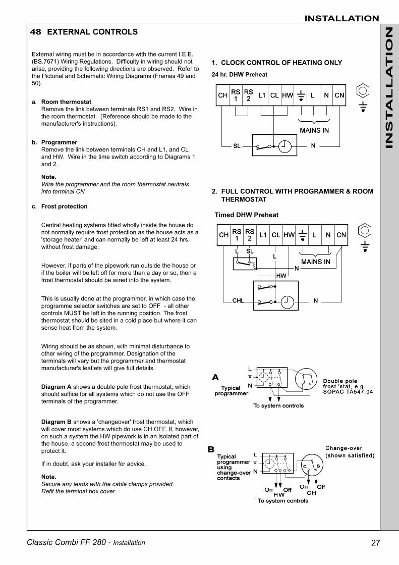
1. CLOCK CONTROL OF HEATING ONLY24 hr. DHW Preheat
2. FULL CONTROL WITH PROGRAMMER & ROOMTHERMOSTAT
Timed DHW Preheat
External wiring must be in accordance with the current I.E.E.(BS.7671) Wiring Regulations. Difficulty in wiring should notarise, providing the following directions are observed. Refer tothe Pictorial and Schematic Wiring Diagrams (Frames 49 and50).
a. Room thermostatRemove the link between terminals RS1 and RS2. Wire inthe room thermostat. (Reference should be made to themanufacturer's instructions).
b. ProgrammerRemove the link between terminals CH and L1, and CLand HW. Wire in the time switch according to Diagrams 1and 2.
Note.Wire the programmer and the room thermostat neutralsinto terminal CN
c. Frost protection
Central heating systems fitted wholly inside the house donot normally require frost protection as the house acts as a'storage heater' and can normally be left at least 24 hrs.without frost damage.
However, if parts of the pipework run outside the house orif the boiler will be left off for more than a day or so, then afrost thermostat should be wired into the system.
This is usually done at the programmer, in which case theprogramme selector switches are set to OFF - all othercontrols MUST be left in the running position. The frostthermostat should be sited in a cold place but where it cansense heat from the system.
Wiring should be as shown, with minimal disturbance toother wiring of the programmer. Designation of theterminals will vary but the programmer and thermostatmanufacturer's leaflets will give full details.
Diagram A shows a double pole frost thermostat, whichshould suffice for all systems which do not use the OFFterminals of the programmer.
Diagram B shows a 'changeover' frost thermostat, whichwill cover most systems which do use CH OFF. If, however,on such a system the HW pipework is in an isolated part ofthe house, a second frost thermostat may be used toprotect it.
If in doubt, ask your installer for advice.
Note.Secure any leads with the cable clamps provided.Refit the terminal box cover.
48 EXTERNAL CONTROLS

Classic Combi FF 280 - Installation28
49 PICTORIAL WIRING DIAGRAM
50 SCHEMATIC WIRING DIAGRAM
INS
TA
LL
AT
ION
INSTALLATION
LEGENDb bluebk black
g/y green/yellowbk/w black/white
br brownr red
y yelloww white
v violetgy grey
LEGEND
b bluebk blackbr brownr redy yelloww whiteg/y green/yellowbk/w black/whitev violetgy grey

Classic Combi FF 280 - Installation 29
INSTALLATION51 COMMISSIONING AND TESTING
52 INITIAL LIGHTINGBoiler module
Lift the boiler casing up to the boiler assembly and secure with4 captive screws.
Controls casing podLocate the pod on the 2 fixing screws. Push the pod forward toengage in the keyhole slots and tighten the fixing screws.
Combi module coverLift the cover up to the module and push forward to engage inthe keyhole slots. Secure with the 2 1/2" pozi screw provided.
continuing until the pilot is established. The main burner willthen light at low rate, approximately 6.0mb (2.4 in.w.g.) burnerpressure. If this sequence does not occur refer to the FaultFinding section.
8. Check that the pilot flame envelops the ignition / detectionelectrode. If the pilot flame appears incorrect refer to 'PilotBurner Replacement' in the Servicing section.
9. Test for gas soundness around ALL boiler gas components,using leak detection fluid. Particularly check gas valve flanges.
10. Set the burner on/off switch to OFF.
INS
TA
LL
AT
ION
(a) Electrical Installation1. Checks to ensure electrical safety should be carried out by
a competent person.
2. ALWAYS carry out preliminary electrical system checks, i.e.earth continuity, polarity, resistance to earth and shortcircuit using a suitable test meter.
(b) Gas Installation1. The whole of the gas installation, including the meter,
MUST be inspected and tested for soundness and purgedin accordance with the recommendations of BS. 6891.
2. Purging air from the gas installation may be expedited byloosening the union on the gas service cock on the boilerand purging until gas is detected.
3. Retighten the union and check for gas soundness.
WARNING. Whilst effecting the required gas soundness test and purging air from the gas installation open all windows anddoors, extinguish naked lights and DO NOT SMOKE.
The casing mustseat correctlyand compressthe sealing stripto make anairtight joint.Visually checkthe side sealsbut if sideclearances arelimited thencheck that thetop and bottomedges of thecasing arecorrectlylocated.
1. Check that the electricity supply is OFF.
2. Check that all the drain cocks are closed and the centralheating isolating valves (J and K) and the domestic hot waterisolating valve (M) are OPEN. Check that the diverter valvemanual lever is in the CLOSED position. Refer to Frame 42.
3. Check that the gas service cock (F) is OPEN. Also check thatthe CH switch (B) and burner on/off switch (C) are OFF.
4. Fit the boiler casing but do not fit the Combi module cover orthe controls casing pod.
WARNING. Do NOT operate the boiler with the casingremoved as damage to the control box may result
5. Slacken the screw in the burner pressure test point (I) andconnect a gas pressure gauge via a flexible tube.
6. Switch the electricity supply ON and check that all externalcontrols are calling for heat: The pump will start.
TO LIGHT THE BOILER7. Set the burner on/off switch to ON and the fan (and pump) will
start. After the fan has run for a few seconds the pilot solenoidvalve will open and the intermittent spark commence,
LEGENDA SightglassB CH / HW switchC Burner on/off switchD Overheat thermostat reset buttonE CH pressure gaugeF Gas service cock.G Inlet pressure test point
H Main burner pressureadjuster (outer)
I Burner pressure test pointJ CH flow isolating valveK CH return isolating valveL DHW outletM DHW inlet isolating valve.N Low rate adjusting
screw (inner)
FITTING THE BOILER CASING

Classic Combi FF 280 - Installation30
DOMESTIC HOT WATER1. With the burner firing as above, fully open a DHW tap and
set the CH/HW switch (B) to HW ONLY. Check that:a. The pump continues to run.b. The diverter valve de-energises.c. The burner continues to fire at maximum rate.
2. Reduce the DHW draw-off rate to the minimum required tokeep the boiler firing. The DHW control operates at aburner pressure of 6.0mb (2.4 in.w.g.). Should it benecessary to adjust the burner pressure turn the inneradjusting screw (N) in either direction until the desiredburner pressure is achieved. Refer to Frame 52.Note. Recheck the maximum burner pressure (CH) aftersetting the minimum burner pressure (HW) and adjust asnecessary.
3. Turn off the DHW tap and set the burner on/off switch toOFF.
53 INITIAL LIGHTING - continuedINSTALLATION
54 GENERAL CHECKSDOMESTIC HOT WATER MODE1. Set the CH/HW switch (B) to HW ONLY and the burner on/off
switch (C) to ON. The pump should start circulating waterthrough the DHW calorifier and the burner should fire atminimum rate for about 3 minutes, preheating the DHWcalorifier.
a. If no DHW is drawn off the boiler will fire periodically for ashort time to maintain the calorifier temperature.
b. The DHW preheat operates 24 hours a day unless aprogrammer is fitted, when it can be timed.
2. Fully open a DHW tap. Check that the pump starts and the mainburner fires at maximum rate. Check that DHW is delivered.
3. Reduce the DHW draw-off rate to the minimum required tokeep the boiler firing and check that the burner pressurereduces to low rate in response to DHW temperature rise.
4. Close the DHW tap and check that the main burnerextinguishes and the pump stops.
CENTRAL HEATING AND DOMESTIC HOT WATER MODE1. Set the CH/HW switch (B) to CH & HW. Check that the main
burner fires at the maximum rate.
2. Fully open a DHW tap and check that the hot water is delivered.
3. Close the DHW tap and turn off the CH/HW switch (B). Checkthat the main burner extinguishes and the pump stops.
4. Check the correct operation of the programmer, if fitted, and allother system controls. Operate each control separately andcheck that the main burner responds.
5. Remove the pressure gauge and tube. Tighten the sealingscrew in the pressure test point, ensuring that a gas-tight sealis made.
WATER CIRCULATING SYSTEM1. With the system COLD, check that the initial pressure is
correct to the system design requirements. For pre-pressurised systems this should be 1.0 bar (14.5 psi).
2. Set the RED fill pressure indicator on the pressure gauge (E)to the initial system pressure. Refer to Frame 4 'Filling'.
INS
TA
LL
AT
ION
CENTRAL HEATING1. Set the CH/HW switch (B) to CH & HW, and the burner on/
off switch (C) to ON. Check that:a. The pump is running.b. The diverter valve energises - no resistance should be
felt when the manual lever is moved by hand.c. The fan starts and the main burner cross-lights
smoothly at maximum rate.Note. The burner may fire initially at low rate but shouldincrease to maximum rate after 1-2 minutes.
2. Operate the boiler for 10 minutes to stabilise the burnertemperature.
3. The boiler CH control operates at a burner pressure of16.0mb (6.4 in.w.g.). Should it be necessary to adjust theburner pressure remove the plastic cover (refer to Frame52) then turn the outer adjusting screw (H) in eitherdirection until the correct pressure is achieved.
Note. Burner setting pressures and boiler performance detailsare given in Tables 2 & 3 and on the data plate, located on thecontrol support frame.
3. With the system still hot, examine all water connections forsoundness. The system pressure will increase withtemperature rise but should not exceed 2.5 bar (36.6 psi).
4. With the system still hot, turn off the gas, water and electricitysupplies to the boiler and drain down, in order to complete theflushing process.
5. Refill and vent the system, as described in 'Guide to SystemRequirements', clear all air locks and again check for watersoundness.
6. Reset the system initial pressure to the design requirement.7. Balance the system.
FINALLY1. Fit the Combi module cover. Refer to Frame 52.2. Refit the controls casing pod and tighten the 2 front fixing
screws.3. Set the controls to the user's requirements and close the pod
door.• The design water output temperatures are as
follows:Central Htg 820C maximumDomestic 700C approx at 3.5 l/min (nominal) draw-offHot Water 350C temperature rise at 9.6 l/min draw-off
• If a programmer is fitted refer to the programmerinstructions.
4. Check that the casing is seated correctly and is compressingthe sealing strip all around the casing.
IMPORTANT.It is absolutely essential to ensure, in practice, that productsof combustion discharging from the terminal cannot re-enterthe building, or any other adjacent building, throughventilators, windows, doors, other sources of natural airinfiltration or forced ventilation/air conditioning.If this should occur the appliance must be TURNED OFFIMMEDIATELY and the local gas supplier called toinvestigate.
WARNING. Do not operate the boiler with the casing removed.

Classic Combi FF 280 - Installation 31
55 HANDING OVERINSTALLATION
After completing the installation and commissioning ofthe system the installer should hand over to thehouseholder by the following actions:
1. Hand the User's Instructions to the Householder andexplain his or her responsibilities under the Gas Safety(Installation and Use) Regulations 1994.
2. Draw attention to the Lighting Instruction label affixed to thecontrols pod door.
3. Explain and demonstrate the lighting and shutting downprocedures.
4. The operation of the boiler and the use and adjustment ofALL system controls should be fully explained to theHouseholder, to ensure the greatest possible fuel economyconsistent with household requirements of both heatingand hot water consumption.Advise the User of the precautions necessary to preventdamage to the system and to the building, in the event ofthe system remaining inoperative during frosty conditions.
5. Explain the function and the use of the boiler heating anddomestic hot water controls.
6. Explain the function of the boiler overheat thermostat andemphasise that if cutout occurs, the boiler should beturned off and a CORGI registered installer consulted.
7. Explain and demonstrate the function of time andtemperature controls, radiator valves etc., for theeconomic use of the system.
8. If any Programmer Kit is fitted, then draw attention tothe Programmer Kit User's Instructions and hand themto the Householder.
9. Loss of system water pressure
Explain that the dial on the Combi module indicates thecentral heating system pressure and that if the normalCOLD pressure of the system (indicated by the redarrow in the dial) is seen to decrease over a period oftime then a water leak is indicated. In this event aCORGI registered installer should be consulted.
DO NOT FIRE THE BOILER IF THE PRESSURE HASREDUCED TO ZERO FROM THE ORIGINALSETTING
10. Stress the importance of regular servicing by a CORGIregistered installer and that a comprehensive serviceshould be carried out AT LEAST ONCE A YEAR.
INS
TA
LL
AT
ION

Classic Combi FF 280 - Installation32
SERVICING56 SCHEDULE
58 BURNER AND AIR BOX REMOVAL1. Remove the screw retaining the front burner support bracket
to the combustion chamber. Remove the M5 pozi-screwsituated at the LH bottom rear of the burner and pull theburner downward to disengage the retention tab. Removeburner to a safe place for inspection and cleaning.
2. Remove the control box fixing screw. Pull the box forwardand downward to disengage.
3. Pull the HT lead connection off the printed circuit board andpull the lead upwards through the bottom panel grommet.
4. Remove the 4 screws retaining the air box /pilot assemblyto the vertical manifold and carefully remove the assembly.
To ensure the continued safe and efficient operation of theappliance it is recommended that it is checked at regularintervals and serviced as necessary. The frequency ofservicing will depend upon the installation condition andusage, but should be carried out at least annually. It is thelaw that any service work must be carried out by a CORGIregistered installer.
a. Light the boiler and, using the flue sampling point(provided on the top RH side of the back panel), carryout a pre-service check, noting any operational faults.
b. Clean the main burner.
c. Clean the heat exchanger.
d. Clean the main and pilot injectors.
e. Remove any debris from inside the base of the casing.
f. Check that the flue terminal is unobstructed and thatthe flue system, including the inner cover, is sealedcorrectly.
g. If the appliance has been installed in a compartment,check that the ventilation areas are clear.
The servicing procedures are covered more fully inFrames 57 to 63 and must be carried out in sequence.
WARNING. Disconnect the electrical supply and turn off thegas supply.
IMPORTANT. After completing the servicing or exchangeof components always test for gas soundness and carryout functional checks as appropriate.
When work is complete the casing MUST be correctlyrefitted, ensuring that a good seal is made.The boiler must NOT be operated if the casing is notfitted.
Note. In order to carry out either servicing or replacementof components, the boiler casing must be removed(Frame 57).
SE
RV
ICIN
G
57 BOILER CASING REMOVALCombi Module Cover
Release the securing screw and withdraw the cover.
Boiler Casing
1. Open the controls pod door.
2. Release the 4 captive screws at the top and bottom of thecasing. Lift the casing off the boiler and retain in a safeplace .
3. Isolate the gas supply at the service cock fitted to theboiler. Refer to Frame 64.

Classic Combi FF 280 - Installation 33
SERVICING
1. Remove the 2 silicon rubber tubes from the fan sensingpoints.
2. Disconnect the fan leads and the fan earth connection.
3a. Rear flueSlacken the M4 screw securing the flue connector to thefan. Disconnect the connector from the fan and slide intothe flue.
3b.Side flueSlacken off two M4 screws securing the flue elbow andflue connector. Disconnect the flue connector from theelbow and slide into the flue. Remove the flue elbow.
4. Disconnect the silicon rubber tube from the rear of thecollector hood.
5. Slacken the two M5 nuts on the front tie rods, releasingthe tie rods from the combustion chamber.
6. Remove the M5 central fixing screw at the rear of thecollector hood and remove collector hood/fan assembly.
7. Check that the fan impeller runs freely. Remove anydebris from the impeller with a soft brush.
8. Remove the flue baffle clips and remove the flue baffles.
59 CLEANING THE FAN ASSEMBLY / THE FLUEWAYS
1. Brush off any deposits that may have fallen on to theburner head, ensuring the flame ports are unobstructed,and remove any debris that may have collected.Note. Brushes with metallic bristles must not be used.
2. Remove the main burner injector and ensure there is noblockage or damage. Clean or renew as necessary.
3. Refit the injector, using an approved jointing compoundsparingly.
4. Inspect the pilot burner and ignition / detection electrode.Ensure that they are clean and in good condition. Checkthat:
a. The pilot burner injector is not blocked or damaged.Refer to Frame 68 for removal details.
b. The pilot burner is clean and unobstructed.c. The ignition / detection electrode is clean and
undamaged.e. The ignition / detection lead is in good condition.f. The spark gap is correct (Frame 68). Clean or renew as
necessary.Note. The pilot shield is located around the pilot assemblybracket and is located by the electrode retaining nut.
5. Refit the control box.
6. Reconnect the gas supply and the electrical wiring. Refer toFrames 41 and 46.
7. Check the sightglass in the boiler casing. Clean or renewas necessary. Refer to Frame 65.
8. Check for gas soundness. Check the gas service cock andpressure test point.
9. Refit the boiler casing and tighten the 4 captive screws.
IMPORTANT.
When work is complete the casing must be correctlyrefitted. Ensure that a good seal is made.
10. Close the controls pod door.
9. Remove all loose deposits from the heat exchanger,particularly between the fins, using a suitable brush.
10. Reassemble in reverse order, ensuring that the fan leads,fan earth connection and 3 sensing tubes are reconnected.
SE
RV
ICIN
GReassemble the boiler in the following order:
1. Refit the flue baffles.
2. Inspect the collector hood rope gasket and replace, ifnecessary, ensuring that the self adhesive rope is fittedcentrally onto the lip of the collector hood /fan assembly.
The boiler efficiency will be adversely affected if incorrectlyfitted.
Refit the collector hood and retain with the 2 front tie rodsand the rear central fixing screws. Tighten the nuts andscrew. Ensure that the sealing gasket is compressed.
3. Refit the 3 sensing tubes and reconnect the electricalleads.
4. Refit the air box assembly and burner. Ensure that theburner front fixing is refitted.
61 RE-ASSEMBLY
60 CLEANING THE BURNER AND PILOT ASSEMBLY

Classic Combi FF 280 - Installation34
SERVICING62 CLEANING THE DOMESTIC HOT
WATER (DHW) FILTER
1. Remove the DHW flow switch. Refer to Frame 79.
2. Prise the filter from the housing in the flow switch inletand clean or renew as necessary.
SE
RV
ICIN
G
63 GAS PRESSURE ADJUSTMENT
PILOTLight the boiler and check that the pilot flame envelops theignition / detection electrode.
The pilot is factory set to maximum and no furtheradjustment is possible. If, however, the pilot flame length isincorrect then remove and inspect the pilot injector. Refer toFrame 68.Relight in accordance with 'Initial lighting', Frames 52 and53.
MAIN BURNER
After any servicing, reference should be made to Table 2,which quotes details of the rated output with the relatedburner setting pressure and the heat input.
Any required adjustments should be made by using thepressure adjustment screw.
Refer to 'Initial Lighting', Frame 52.

Classic Combi FF 280 - Installation 35
Note. In order to assist fault finding, the control box printed circuitboard is fitted with 4 indicator lights which represent the followingboiler conditions:
Neon I1 Air pressure switch made.
Neon I2 Fan voltage indication
Neon I3 Main supply to PCB 25B.
Neon SGI Flashes to indicate spark operation(stops after detection).
Refer also to Frame 64
1. Remove the control box fixing screw.
67 CH OVERHEAT THERMOSTAT REPLACEMENT2. Pull the box forward and downward to disengage.
3. To remove the overheatthermostat pull off theelectrical connections atthe thermostat. Removethe backnut retaining thethermostat to the bracket.Remove the thermostatfrom the heat exchangerpocket.
4. Reassemble in reverseorder.
65 SIGHTGLASS REPLACEMENT1. Refer to Frame 64.2. Unfasten the 2 nuts and washers holding the sightglass
assembly to the casing front panel.3. When fixing the new assembly ensure that the parts are in
the correct order. The frame must have the return edge atthe bottom.
4. Retighten the 2 nuts to ensure an airtight seal. DO NOTOVERTIGHTEN.
5. Replace the boiler casing. Refer to Frame 52.
66 DHW PREHEAT, CONTROL, OVERHEAT AND CH CONTROL THERMOSTATREPLACEMENT
1. Refer to Frame 64.
2. Release the retaining screw and hang the CH expansionvessel in the servicing position. Refer to Frame 45.
3. Remove the 2 securing screws and withdraw the faultythermostat.
4. Pull off the 2 electrical leads from the thermostat.
5. Fit the new thermostat and re-assemble in reverse order(polarity is immaterial).
THE BOILER MUST NOT BE OPERATED IF THE CASING IS NOT FITTED
64 GENERAL
When replacing any component:1. Isolate the electricity supply.
2. Turn OFF the gas supply.
3. Remove the boiler casings. Refer to Frame 57.
IMPORTANT. When work is complete the casing must becorrectly refitted, ensuring that a good seal is made.
REPLACEMENT OF PARTS
SE
RV
ICIN
G
SERVICING

Classic Combi FF 280 - Installation36
68 PILOT BURNER REPLACEMENT
1. Refer to Frame 64.2. Remove the burner and air box assembly.
Refer to Frame 58.3. Remove the electrode retaining nut and remove the pilot
shield and electrode.4. Unscrew the central pilot fixing screw and lift the pilot clear
of the pilot injector. The pilot injector may now beunscrewed if required.
5. Replace the pilot burner and retain with the M4 screwpreviously removed. Ensure that the copper sealing washeris replaced when refitting the pilot injector.
70 MAIN BURNER & MAIN BURNER INJECTOR REPLACEMENT1. Refer to Frame 64
2. Remove the screw retaining the front burner support bracketto the combustion chamber.
3. Remove the M5 pozi screw and washer, situated at the lefthand bottom rear of the burner. Pull the burner downward todisengage the retention tab and remove the burner.
4. At this stage the main burner injector can be removed,checked, cleaned or replaced as required. Ensure that anapproved jointing compound is used sparingly.
5. Fit the new burner, ensuring that the retention tab is correctlylocated in the air box slot.
6. Refit the M5 retaining screw and washer.
7. Refit the boiler casing.
8. Check the burner for cross-lighting and flame stability.
1. Refer to Frame 64.
2. Remove the burner and air box assembly. Refer to Frame 58.
3. Remove the electrode retaining nut.
4. Remove the pilot shield.
5. Remove the spark electrode and integral lead.
6. Fit the new electrode and lead in reverse order.Ensure that the pilot shield is replaced.
7. Check the spark gap. Refer to Frame 68.
8. Replace the boiler casing.
9. Check the pilot ignition.
69 SPARK ELECTRODE AND LEAD REPLACEMENT
6. Replace the electrode and pilot shield, retaining both withthe electrode nut. Check the spark gap.
7. Replace the box assembly.
8. Replace the burner.
9. Replace the boiler casing.
10. The pilot is factory set to maximum and no furtheradjustment is possible. Ensure that there is an inletpressure of 20 mbar available. Also check burner ignitionand cross-lighting.
SE
RV
ICIN
GSERVICING

Classic Combi FF 280 - Installation 37
SERVICING
71 COMBUSTION CHAMBER INSULATION REPLACEMENT1. Refer to Frame 64
2. Remove the burner and air box assembly. Refer to Frame 58.
3. Remove the tie rods and combustion chamber.
4. Remove the 2 side panel retaining brackets.
5. Remove the side insulation panels.
6. Remove the front and rear insulation panels.
7. Fit the new front and rear insulation panels.
8. Fit the new side panels and retain with the brackets andscrews previously removed.
9. Refit the combustion chamber and tie rods.
10. Re-assemble the rest of the appliance in reverse order.
72 GAS CONTROL VALVE REPLACEMENT
7. Remove the gas control / manifold assembly.
8. Remove the 4 screws retaining the manifold to the gascontrol valve and fit the manifold to the new gas controlvalve. Ensure that the new control is fitted the correct wayround (an arrow engraved on the back indicates thedirection of flow).
Note. Remove the gas cock stub and refit into the newgas control valve. Use an approved jointing compound onthe pipe stub.
9. Reassemble in reverse order.
10. Replace the boiler casing.
11. Check the gas valve operation / gas soundness.
SE
RV
ICIN
G
Note. Also refer to Frames 93 & 94, 'Exploded Views' , for illustration of the procedure detailed below.
1. Refer to Frame 64.
2. Remove the burner support bracket, burner and air boxassembly. Refer to Frame 58.
3. Remove the control box fixing screw. Pull the boxforward and downward to disengage.
4. Remove the gas control valve electrical connections.
5. Disconnect and remove the gas union from the gascontrol valve.
6. Whilst supporting the gas control valve, remove the 2screws retaining the manifold to the back panel.
73 FAN REPLACEMENT1. Remove the 2 silicon rubber tubes from the fan sensing points.
2. Disconnect the fan leads and the fan earth connection.
3a. Rear flue: Slacken the M4 screw securing the flue connector to the fan.Disconnect the connector from the fan and slide into the flue.
3b.Side flue: Slacken off two M4 screws securing the flue elbow and flueconnector. Disconnect the flue connector from the elbow and slide intothe flue. Remove the flue elbow.
4. Disconnect the silicon rubber tube from the rear of the collector hood.
5. Slacken the two M5 nuts on the front tie rods, releasing the tie rods fromthe combustion chamber.
6. Remove the M5 central fixing screw at the rear of the collector hood andremove collector hood/fan assembly.
7. Remove the three M4 screws retaining the fan to the collector hood.
8. Reassemble in reverse order, ensuring the fan leads, fan earthconnection and 3 sensing tubes are reconnected.
9. Refit the boiler casing.
10. Check the boiler operation.

Classic Combi FF 280 - Installation38
76 PRINTED CIRCUIT BOARD (PCB) REPLACEMENT
74 AIR PRESSURE SWITCH (APS) REPLACEMENT
75 BURNER ON/OFF AND CH/HW SWITCH REPLACEMENT1. Refer to Frame 64.2. Remove the control box fixing screw, pull the box forward
and downward to disengage.3. Disconnect the 2 electrical leads from the switch.4. BURNER ON/OFF SWITCH ONLY
Compress the retaining clips and prise the defective switchout of the front panel.CH / HW SWITCH ONLYa. Pull off the knob.b. Remove the backnut and withdraw the switch.
5. Connect the new switch in reverse order. Ensure that theswitch is the correct way round, i.e. with the terminalstowards the right, as shown (burner on/off switch) or thatthe switch is correctly orientated (CH/HW switch). Polarityis immaterial
Note. Refer to Frames 93 and 94, 'Exploded Views' for illustration of the procedure detailed below.
6. Refit the boiler casing.7. Check the switch operation.
SE
RV
ICIN
GSERVICING
1. Refer to Frame 64.
2. Remove the control box fixing screw. Pull the box forwardand downward to disengage.
3. Remove the HT lead from the PCB
4. Remove the 4 push-in electrical connectors from the PCB.
5. Remove the neutral wire on the PCB from its connection tothe back of the socket inside the control box.
6. Remove the earth wire on the PCB from its connection tothe earth stud inside the control box.
7. Remove the 2 connections from the on/off switch andremove the switch.
8. Compress the barbs on the PCB stand-offs to release thePCB from the box.
9. Fit the new PCB and reassemble in reverse order.
10. Refit the boiler jacket.
11. Check the operation of the boiler.
12. Check the ignition operation.
1. Refer to Frame 64.
2. Remove the control box fixing screw. Pull the box forwardand downward to disengage.
3. Pull off both sensing tubes from the APS and remove thecover.
4. Remove the 3 electrical connections from the APS.
5. Remove the switch from the controls box.
6. Connect the new switch in reverse order.
7. Refit the control box.
8. Refit the boiler casing.
9. Check the boiler operation.

Classic Combi FF 280 - Installation 39
78 DIVERTER VALVE ACTUATOR REPLACEMENT
1. Refer to Frame 64 (The Combi module cover only need beremoved.)
2. Release the retaining screw and hang the CH expansionvessel in the servicing position. Refer to Frame 45.
3. Disconnect the diverter valve at the inlineconnector.
4. Release the captive screw (A)and lift off the valvecover.
5. SET THE MANUALLYOPERATED VALVELEVER TO OPEN.
6. Release the 2 captivescrews (B) and lift theactuator off the valve body.
Note. At this stage, if required, theSyncron motor may be replaced. Refer tothe instructions supplied with the replacementmotor.
7. Fit the new actuator. PRESET TO THE OPEN POSITIONand reassemble in reverse order.
77 LOGIC PCB 27 REPLACEMENT
Logic PCB 27
1. Refer to Frame 64 (The Combi module cover only need be removed.)
2. Release the retaining screw and hang the CH expansion vessel in the servicingposition. Refer to Frame 45.
3. Withdraw the PCB and unplug the 8 electrical leads(A to H).
4. Fit the new PCB 27 and re-assemble in reverse order.
SERVICING
SE
RV
ICIN
G

Classic Combi FF 280 - Installation40
79 DHW FLOW SWITCH REPLACEMENT
81 DRAINING THE BOILER
6. Open the lowest DHW draw-off tap.
7. Drain any residual water into a receptacle via the DHWdrain point.
8. Undo the DHW outlet pipe union nuts A & B and move thepipe aside.
9. Undo the DHW inlet pipe union nuts C & D and withdrawthe switch assembly.
10. Transfer the pipes and DHW filter. Refer to Frame 80.
11. Fit the new flow switch complete with new sealingwashers, ensuring that the switch is fitted the right way
round. An arrow on the switch head indicates thedirection of flow (downward).
12. Re-assemble in reverse order.
Note. Refer to Frames 92 and 93 (Boiler and Combimodules - exploded views) for illustration of the proceduredetailed below:
1. Refer to Frame 64.
2. Close the CH isolating valves.
3. Remove the heat exchanger drain plug, using a 3/16"Allen key, and drain the water into a suitable receptacle.
4. Refit the drain plug, using a suitable jointing compound.
5. In order to refill the boiler refer to Frame 4.
80 DHW FILTER REPLACEMENT
1. Refer to Frame 64 (The Combi module cover only needbe removed).
2. Remove the DHW flow switch. Refer to Frame 79.
3. Prise the filter fromthe housing inthe flowswitch inlet,and cleanor renew asnecessary.
4. Re-assemble inreverse order.
1. Refer to Frame 64 (the Combi module cover only need beremoved).
2. Release the retaining screw and hang the CH expansionvessel in the servicing position. Refer to Frame 45.
3. Disconnect the flow switch lead from the Logic PCB 27.
4. Remove the 2 securing screws and withdraw the pipesupport bracket.
5. Close the DHW isolating valve.
SERVICINGS
ER
VIC
ING
IMPORTANT.In order to replace the components in Frames 82 to 90 it isnecessary to drain the boiler.

Classic Combi FF 280 - Installation 41
82 PRESSURE GAUGE REPLACEMENT
83 CH EXPANSION VESSEL REPLACEMENT
6. Fit the new gauge and re-assemble in reverse order,ensuring that:
a. The capillary is carefully and neatly routed, aspreviously.
b. The gauge is correctly orientated within thehousing.
1. Refer to Frame 64.
2. Drain the boiler. Refer to Frame 81.
3. Release the retaining screw and hang the CH expansionvessel in the servicing position. Refer to Frame 45.
4. Disconnect the pressure gauge capillary from the safetyvalve.
5. Compress the 2 retaining lugs and withdraw the gaugefrom the bracket.
1. Refer to Frame 64.
2. Drain the boiler. Refer to Frame 81.
3. Disconnect the flexible pipe from the vessel.
4. Release the retaining screw and withdraw the expansionvessel.
5. Fit the new expansion vessel, complete with the newsealing washer, and re-assemble in reverse order.
SERVICING
SE
RV
ICIN
G

Classic Combi FF 280 - Installation42
85 DIVERTER VALVE (COMPLETE) REPLACEMENT
84 DHW CALORIFIER REPLACEMENT1. Refer to Frame 64.
2. Drain the boiler. Refer to Frame 81.
3. Remove the CH expansion vessel. Refer to Frame 45.
4. Remove the 2 securing screws and withdraw the pipesupport bracket.
5. Close the DHW inlet isolating valve.
6. Open the lowest DHW draw-off tap.
7. Drain any residual water into a receptacle via the DHWdrain point.
8. Undo the unions on the DHW inlet pipe and move the pipeaside.
9. Slacken diverter valve union nut C.
10. Undo calorifier union nut D.
11. Undo calorifier unions A and B and withdraw the calorifierfrom the boiler.
12. Fit the new calorifier, complete with the new sealingwashers provided, and re-assemble in reverse order.
TO DESCALE THE CALORIFIER:
a. Remove the calorifier from the boiler as describedabove.
b. Descale the domestic hot water coil, using a proprietarydescaling agent.
c. Rinse thoroughly with clean water.
d. Re-assemble in reverse order.
WARNING. The agents are highly corrosive - ingestion orcontact with skin, eyes and clothing MUST be avoided.Protective clothing should be worn and the descalingoperation conducted out of doors in a well ventilated area.
Note. The names and addresses of suppliers of suitabledescaling agents are given in Frame 4.
1. Refer to Frame 64.
2. Drain the boiler. Refer to Frame 81.
3. Remove the CH expansion vessel. Refer to Frame 45.
4. Remove the automatic air vent. Refer to Frame 88.
5. Disconnect the diverter valve lead at the inline connector.
6. Undo diverter valve union A and the bypass union.
7. Slacken the CH flow pipe union.
8. Undo diverter valve union B.
9. Slacken diverter valve union nut C as far back as possible.
10. Prevent union nut C from turning and undo calorifier unionnut D. This will jack the diverter valve towards the rightand permit its withdrawal from the boiler, complete withstub pipe.
11. Transfer the stub pipe to the new valve.
12. Fit the new diverter valve and re-assemble in reverseorder.
SERVICINGS
ER
VIC
ING

Classic Combi FF 280 - Installation 43
gaskets provided, transfer the boiler return pipe to the newpump.
12. Fit the new pump and re-assemble in reverse order,ensuring that:
a. The new sealing gasket provided is fitted at the pumpreturn union.
b. The electrical connections are correctly remade. (Referto the diagram inside the terminal box cover).
c. The pump selector switch cover is correctly fitted andthat the switch is set at position 3.
87 SAFETY VALVE REPLACEMENT
86 PUMP REPLACEMENT1. Refer to Frame 64.
2. Drain the boiler. Refer to Frame 81.
3. Remove the CH expansion vessel. Refer to Frame 45.
4. Disconnect the pressure gauge capillary from thesafety valve. Refer to Frame 82.
5. Slacken the 2 securing screws and remove the CHexpansion vessel support bracket. Refer to Frame 45.
6. Remove the pump terminal box cover and disconnectthe electrical leads.
7. Slide the cable entry out and withdraw the cable fromthe terminal box.
Note. If required, the PUMP HEAD ONLY may now bereplaced.
a. Remove the 4 socket screws and withdraw thepump head.
b. Fit the new head and re-assemble in reverse order.
To remove the COMPLETE pump, proceed as follows:
8. Undo the boiler return elbow unions.
9. Undo the pump return union.
10. Swing the pump to disengage the boiler return pipefrom the clip and withdraw the pump, complete withreturn pipe.
11. Undo the pump flow union and, using one of the new
1. Refer to Frame 64.
2. Drain the boiler. Refer to Frame 81.
3. Remove the CH expansion vessel. Refer to Frame 45.
4. Remove the 2 securing screws and withdraw the pipesupport bracket. Refer to Frame 45.
5. Disconnect the pressure gauge capillary from the safetyvalve.
6. Disconnect the overflowpipe at the bulkheadfitting on top of the wallmounting plate.
7. Undo the safety valveunion and withdraw thevalve, complete with theoverflow pipe.
8. Transfer the overflow pipe to the new valve, ensuring thatits orientation is the same as that of the previousassembly (use the arrow engraved on the side of thevalve to aid realignment).
9. Fit the new safety valve, complete with the new sealingwashers provided, and re-assemble in reverse order.
SE
RV
ICIN
G
SERVICING
Overflow pipeunion

Classic Combi FF 280 - Installation44
90 BOILER HEAT EXCHANGER REPLACEMENT
88 AUTOMATIC AIR VENT REPLACEMENT1. Refer to Frame 64.
2. Drain the boiler. Refer to Frame 81.
3. Unscrew the automatic air vent from the boiler flowheader, applying an appropriate counter-force to theboss, in order to prevent damage.
4. Fit the new air vent, using the 'O' ring provided, and re-assemble in reverse order.
IMPORTANT. Ensure that the vent cap is loose.
89 CH THERMOSTATIC VALVEREPLACEMENT
1. Refer to Frame 64.
2. Drain the boiler. Refer to Frame 81.
3. Remove the CH expansion vessel. Refer to Frame 45.
4. Remove the automatic air vent. Refer to Frame 88.
5. Remove the 2 securing screws and withdraw the pipe supportbracket. Refer to Frame 79.
6. Undo the diverter valve union A, the bypass union B and thethermostat top union C.
7. Swing the flow pipe to the right to clear the diverter valveunion, unclip and withdraw the pipe, complete with thermostat.
8. Transfer the flow pipe to the new thermostat and re-assemblein reverse order, using the new sealing washers provided.
SE
RV
ICIN
GSERVICING
IMPORTANT.Before starting the removal procedure, protect the gas andelectrical controls with a waterproof sheet or similar.
Note. Refer to Frame 93 'Boiler Assembly - Exploded View'for illustration of the procedure detailed below.
1. Drain the boiler.
2. Remove the CH expansion vessel. Refer to Frame 83.
3. Disconnect the electrical lead.Remove the Combi module - following the procedure (inreverse order) described in Frame 38.
Note. An extraction tool is provided (in the Hardware Pack)to remove the push-fit brass elbow from the boiler andCombi module.
4. Remove the burner / air box assembly. Refer to Frame 58.
5. Remove the fan assembly. Refer to Frame 73.
6. Remove the combustion chamber by unscrewing the 4 tierods.
7. Remove the thermostat sensors from the pockets on theheat exchanger.
8. Slacken 3 turns only the 4 heat exchanger / inter-panelretaining screws.
9. Lift the heat exchanger / inter-panel assembly upward andforward to disengage key hole fixings. Pull the assemblydownward to clear the water pipes from the back panel.
10. Remove the 2 rubber sealing grommets from the top of theback panel to facilitate fitting the new assembly.
11. Fit the new heat exchanger assembly, complete with waterpipes, and hang it on the key hole slots and screws.
12. Retighten the screws.
13. Replace the 2 rubber sealing grommets.
14. Re-assemble in reverse order.
15. Remake all water connections, ensuring that thecompression fittings (if used) are correctly refitted.
16. Fully test all functions, including water and gas soundness.

Classic Combi FF 280 - Installation 45
91 BOILER CASING SEAL REPLACEMENT
92 COMBI MODULE - Exploded View
1. Refer to Frame 64.
2. Remove the old seal from the bottom edge of the casing and alsofrom the edges of the boiler back panel.
3. Fit the new self-adhesive seals.
INNER VIEW OF BOILER CASING
51. Flexible hose
53. CH expansion vessel
104. CH expansion vessel support bracket
A. Pressure gauge height adjustment screws and locking nuts - 2 off.
LEGEND27. Automatic air vent
28. Pressure gauge
32. Safety valve
35. Pump
38. Push-fit elbow
41. Diverter valve
43. CH thermostatic valve
45. Calorifier
47. DHW flow switch
SE
RV
ICIN
G
SERVICING

Classic Combi FF 280 - Installation46
93 BOILER ASSEMBLY - Exploded ViewSERVICING
SE
RV
ICIN
G
LEGEND
1. Heat exchanger2. Flue baffles7. Combustion chamber12. Main burner18. Control box24. Fan / collector hood assembly26a & 26b. Pressure sensing pipes29. CH control thermostat30. DHW preheat thermostat
35. Pump45. Calorifier55. Sealing plates, 2 off58. Wall mounting plate59. Stand-off brackets (LH & RH side)62. Back panel100. DHW inlet isolating valve101. DHW outlet connection102. Safety valve drain connection
103. CH flow and return isolatingvalves
105. Inter-panel106. Pumped return pipe107. Pumped flow pipe108. Rubber sealing grommets109. Overheat thermostat110. Boiler drain point111. Programmer (if fitted)112. Burner support bracket113. Terminal strip cover
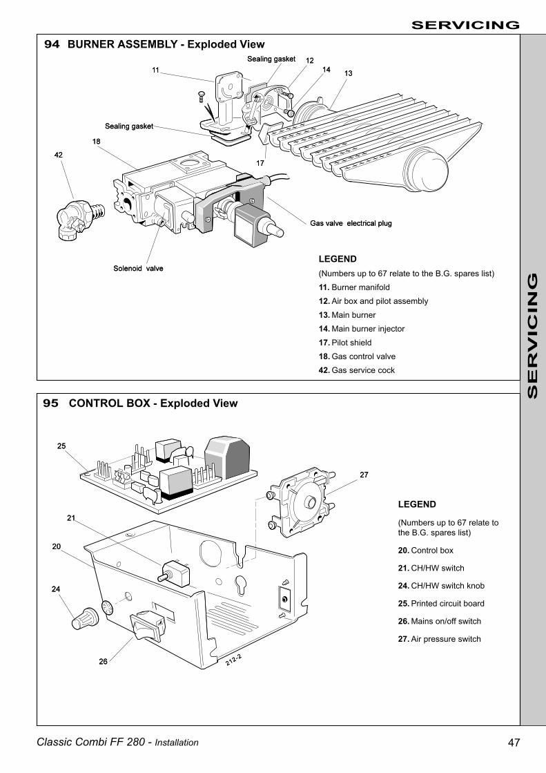
Classic Combi FF 280 - Installation 47
94 BURNER ASSEMBLY - Exploded View
95 CONTROL BOX - Exploded View
LEGEND
(Numbers up to 67 relate tothe B.G. spares list)
20. Control box
21. CH/HW switch
24. CH/HW switch knob
25. Printed circuit board
26. Mains on/off switch
27. Air pressure switch
SERVICING
SE
RV
ICIN
G
LEGEND(Numbers up to 67 relate to the B.G. spares list)11. Burner manifold12. Air box and pilot assembly13. Main burner14. Main burner injector17. Pilot shield18. Gas control valve42. Gas service cock

Classic Combi FF 280 - Installation48
Notes.
1. Ensure that the boiler and system is full of water, free from air locks and that the pump is running.
2. Press the overheat thermostat reset button and continue with the fault finding procedure. Replace the thermostat if it operatesbefore the normal working temperature is reached.
3. In order to assist fault finding, the control box printed circuit board is fitted with 4 indicator lights:
Neon I1 Air pressure switch madeNeon I2 Fan voltage indicationNeon I3 Mains supply to PCB 25B.Neon SGI Flashes to indicate spark operation (stops after detection)
Replace thefan
Check allfuses
Replace thethermostat
Replace theswitch
Has theburner on/offswitch made
contact ?
Replacethe pump
Is the airpressure
switch in theNC position atthe start of the
ignitionsequence ?
Does thefan start ?
Is there asupply
voltage atthe pump ?
Expect230 V AC
+10% -6%
Does thefan start ?
Is there asupply voltage
to the fan ?(230 V
+10% -6%)
Is the DHWthermostatcalling for
heat ?
Has the DHWflowswitchoperated ?
Is the DHWoverheat
thermostatcalling for
heat?
Replace thethermostat
Replace theflow switch
Replace LogicPCB No.27
Switch ON themains supplyand fully opena DHW tap.
Does neon I3
on PCBNo.25B glow ?
Does thepump start ?
Does neon I2
on PCBNo.25B glow?
Switch OFFthe mains
supply,disconnectthe DHWpreheat
thermostat
Does neon I1
on PCBNo.25B glow ?
YES
NO
YES
YES
NO
YES
NO
NONONO
NO
NO
NO
YES
YES YES
Check thatthe pumpis free torotate.
Does thepump now
start ?
NO
NO
NO
NO
YES
YES
NO YES
NO
NO
Before attempting to rectify any electrical fault ALWAYS carry out the preliminary electrical system checks, using a suitable testmeter. Detailed instructions on the replacement of faulty parts are contained within the 'Servicing' section of this publication.
96 DOMESTIC HOT WATER MODE Start from cold. Turn the CH / HW switch to HW ONLY and theburner ON/OFF switch to ON. Also turn any time clock ON andswitch ON the mains electricity supply.
Replace theair pressure
switch
FAULT FINDING
Is there asupply voltageat the mains
input terminalstrip?
Expect 230 VAC +10% -6%
Replace automaticignition PCB
No. 25B
FA
ULT
F
IND
ING
THEN YES
Does neon I2
now glow ?
YES

Classic Combi FF 280 - Installation 49
Is there avoltage at thebypass valveGV3 ? (230 V
AC+10% -6%)
Replaceautomaticignition
PCBNo. 25B
Is therea gassupplyto thepilot ?
Check that theDHW draw-off rate
is greater than6.5 l/min. Is therenow a voltage atgas valve GV3 ?
Replace theDHW controlthermostat
ReplaceLogic PCB
No.27
Has the airpressure
switchoperated ?
Is theboilercasing
correctlyfitted ?
NO
Is the pilotinjector
free fromblockage?
Isthere agoodsparkat thepilot ?
NO
YESYES
Does themain
burnercross-lightfrom thepilot ?
Is theMAXIMUM
burnerpressureattained ?
NONONONO
NO
NO
NO
NO
Is there a regularflash from the tubeon the auto ignition
PCB No. 25B ?
NO
The boiler isoperatingcorrectly
Replacethe gascontrolvalve
Replacethe gascontrolvalve
FAULT FINDING
Check thesensingpipes forblockageand bad
connections.Does the
airpressure
switch nowoperate ?
Replacethe
pressureswitch
NO
YES
Refer toFrame 68.
Check the gapbetween the
electrode andhood. Checkthat the HT
lead andelectrode areundamaged
and thatconnections
are not close toearthed
metalwork
YES YESNO YES
FA
ULT
F
IND
ING
Is there asupply voltage
at the pilotvalve
terminals ?(230 V AC
+10% -6%)
YES
Does thespark
stop afterthe pilothas lit ?
Doesthe pilotlight ?
YES
YES
YES
Replacethe gascontrolvalve
YES YESYES
Is there avoltage at the
main gasvalve? (230 V
AC +10% -6%)
Does theburner
pressurereduce tominimumsetting, in
response toan increase
in theDomesticHot Water
temperature,when the
rate isreduced toless than6 l/min ?

Classic Combi FF 280 - Installation50
97 PREHEAT MODE
Is the airpressure
switch in theNC position atthe start of the
ignitionsequence ?
Does thefan start ?
Is there asupply
voltage atthe pump ?(Expect 230V AC +10%
-6%)
Check all fuses
Replace theswitch
Has the burneron/off switch
made contact ?
Is the boilercasing correctly
fitted ?
Does thefan start ?
Check thesensing pipesfor blockage
and badconnections.Does the air
pressure switchnow operate ?
Does neon I2
now glow ?
Replace thepressure switch
Is there asupply
voltage tothe fan ?(230 V
+10% -6%)
Replace thethermostat
Is the DHW overheatthermostat calling for
heat ?
Replace thethermostat
Is the DHW preheatthermostat calling for
heat ?
Check thatthe pump is
free torotate. Does
the pumpnow start ?
Replace thepump
YES YES Does thepump start ?
Does the neon I3
on PCB No.25Bglow ?
Doesneon I2
glow ?
YES YES YESDoesneon I1
glow ?
NONONO
NO
NO
NO
NO
YES
YES
YES
NO
Has the airpressure switch
operated ?
YESNO
NO
YES
NO
YES
NO
YES
NO
NO
NO
NO
NO
Start from cold. Turn the CH/HW switch to HW ONLY and any time clock ON. Ensure that all DHW taps are OFF.Turn the burner on/off switch ON. Switch ON the mains supply.
Replace the airpressure switch
Replacethe fan
Replace automatic ignition
PCB No. 25B
FAULT FINDING
Is there a supplyvoltage at themains input
terminal strip ?(Expect 230 VAC +10 -6%)
FA
ULT
F
IND
ING
Replace the Logic PCB No.27

Classic Combi FF 280 - Installation 51
Does thepilot light ?
Does thespark stop
after the pilotis lit ?
Does the mainburner cross-
lightfrom the pilot ?
Is theMINIMUM
burnerpressureattained ?
Is there agood spark
at the pilot ?
Is there avoltage atthe bypassvalve GV3 ?
(Expectzero)
Is there avoltage at the
main gasvalve ?
(230 V AC+10% -6%)
Replaceautomatic
ignitionPCB
No.25B
Replace thethermostat
Is the DHWpreheat
thermostatcalling for heat?
Is the pilotinjector
free fromblockage ?
Replace theDHW preheat
thermostat
Is there asupply
voltage atthe pilot
valveterminals ?(230 V AC+10% -6%)
Refer toFrame 68.Check the
gap betweenthe
electrodeand hood.Check thatthe HT lead
andelectrode
areundamaged
and thatconnectionsare not close
to earthedmetalwork
Is there aregular flash
from thetube on
automaticignition PCB
No.25B ?
YESYES YES YES YES
NO
NONONONO
YES
Is therea gassupplyto thepilot ?
YES
NO
YES
YES
Replace thegas control
valve
NO
YES
ReplaceLogic PCB
No.27
YES
YESNO
FAULT FINDING
NO
Does the burnerextinguish after
approx 3minutes, inresponse to
increased boilertemperature ?
FA
ULT
F
IND
ING
Replace thegas control
valve
YES
The boiler isoperatingcorrectly

Classic Combi FF 280 - Installation52
Does thefan start ?
Is the boilercasing correctly
fitted ?
Check thesensing pipesfor blockage
and badconnections.Does the air
pressure switchnow operate ?
Replace thepressure switch
Has the airpressure switch
operated ?
NO
YES
NO
YES
NO
YES
NO
Start from cold. Turn the CH/HW switch to CH & HW, and any time clock and room thermostat ON.Ensure that all DHW taps remain OFF. Turn the burner ON/OFF switch ON. Switch ON the mains supply.
Doesneon I1
glow ?
Replacethe fan
Replacethe air
pressureswitch
Replace automatic ignition
PCB No. 25B
Doesneon I2
glow ?
Doesneon I2
nowglow ?
Does thepumpstart ?
98 CENTRAL HEATING MODE
YES
YES
Is the CHcontrol
thermostatcalling for
heat ?
YES
Has theoverheat
thermostatoperated?
ReplaceLogic PCB
No.27
NO
NO
Is the airpressure
switch in theNC position
at the start ofthe ignitionsequence ?
Checkthat thepump isfree torotate.
Does thepumpnow
start ?
Does thedivertervalve
operate ?
NO NO NO NO
NO
NO YES
Checkthat themanuallever isfree tomove.
Does thevalve now
open?
Replacethe valveactuator
NO
Replacethe pump
NO
YES NO NO
NO
Check allfuses
Replacethe switch
Replace thethermostat
Can thethermostatbe reset ?
Replacethe
thermostat
NO
FAULT FINDINGFA
ULT
F
IND
ING
YESYESYESYESDoes neon I3
on PCBNo.25B glow?
YESIs there asupply
voltage at themains input
terminalstrip? (Expect
230 V AC+10% -6%)
NO
NO
Replacethe switch
Has theCH / HW
switch madecontact ?
Has theburner on/offswitch made
contact ?
NO
NO
YES
YES
Is there asupply
voltage atthe valve?
(Expect 230V AC
+10% -6%)
Is there asupply
voltage atthe pump?
(Expect 230V AC
+10% -6%)
Does thefan start ?
Is there asupply voltage
to the fan ?(Expect 230 V
AC+10% -6%)

Classic Combi FF 280 - Installation 53
NO
Is there agood spark
at the pilot ?
Is therea gassupplyto thepilot ?
Is there asupply
voltage atthe pilot
valveterminals?(230 V AC+10% -6%)
Replace thethermostatic
valve
NO
YES YES YESIs theMAXIMUM
burnerpressureattained ?
NONO
YES
YES
Refer toFrame 68.Check the
gap betweenthe
electrodeand hood.Check thatthe HT lead
andelectrode
areundamaged
and thatconnectionsare not close
to earthedmetalwork
NO YES
Does thespark stopafter the
pilot is lit ?
NO
Replaceautomatic
ignitionPCB
No.25B
YES Does themain burnercross-lightfrom the
pilot?
NO
YES
Replacethe gascontrolvalve
ReplaceLogic PCB
No.27
NO
Replace theCH controlthermostat
NO
FAULT FINDING
Doesthe pilotlight ?
YES YES Does theboiler flow
temperaturerise toapprox600C
beforeallowinghot water
to thesystem
(approx.10mins.)
Does theburner
extinguishin
responseto an
increase in CHtemp-
erature?
The boiler isoperatingcorrectly
NO YES
Replace thegas control
valve
FA
ULT
F
IND
ING
Is there aregular flash
from thetube on
automaticignition PCB
No.25B ?
Is the pilotinjector
free fromblockage ?
Is there avoltage at
the main gasvalve ?
(230 V AC+10% -6%)
Is there avoltage atthe bypassvalve GV3?
(Expect230 V AC
+10% -6%)YES NO

Classic Combi FF 280 - Installation54
Key No. GC Part No. Description Qty. Product No.
8 308 365 Sightglass assembly kit 1 079 602
12 379 919 Main burner: AEROMATIC No. AC 19/123 292 1 111 709
13 398 065 Main burner injector: BRAY Cat. 10 - size 2300; 1 004 444
14 397 943 Pilot burner injector: HONEYWELL 4580 1 004 982
14A 308 358 Pilot burner: HONEYWELL Q359 A 1124 1 079 599
16 -- Gas control valve: HONEYWELL VR 4601 PA 2020 1 111 075
17 308 536 Ignition electrode complete with lead and backnut 1 111 881
18 -- Control box assembly 1 150 615
19 374 073 Rotary on/off switch 1 005 823
21 386 149 Automatic ignition printed circuit board - PACTROL PCB No. 25B 1 079 716
22 386 802 Burner on/off switch:ARROW HART Cygnet Series No. 100 0 11 E (A) 1 004 882
23 -- Pressure switch: HONEYWELL YAMATAKE C6065 A 1010 1 137 990
24 308 536 Fan assembly 1 111 947
27 386 830 Automatic air vent: CALEFFI 5030 1 113 116
28 374 088 Pressure gauge 1 113 089
29 392 921 Thermostat - high setting 1 079 634
30 378 074 DHW preheat thermostat:ELMWOOD 2455 R - 192 / 940 (green dot) 1 079 635
31 378 075 DHW control thermostatELMWOOD 2455 R - 192 / 941 (yellow dot) 1 079 636
32 374 045 Safety valve: CALEFFI 3141 1 113 026
33 374 074 Combi module cover (with fixing screw) 1 079 637
35 374 076 Pump: GRUNDFOS 15 - 50 1 005 595
41 374 081 Diverter valve assy: HONEYWELL 4044 C 1536 1 005 871
43 374 083 CH thermostatic valve 1 005 803
47 374 086 DHW flow switch assy: HONSBERG Fluvatest UM 15 MA 1 005 856
48 378 085 DHW filter: GASCON G - C 901 1 005 810
52 378 076 Logic PCB No.27, PACTROL 1 005 632
53 374 100 CH 8 -litre expansion vessel 1 113 205
54 -- Boiler casing assembly 1 079 947
56 -- Controls casing door 1 079 948
57 308 331 Boiler sealing pack 1 079 605
67 378 087 CH overheat thermostat, RANCO LM7 - P 8508 1 005 900
SHORT LIST OF PARTSThe following are parts commonly required due to damage orexpendability. Their failure or absence is likely to affect safetyor performance of this appliance.
The list is extracted from the British Gas List of Parts, whichcontains all available spare parts.
The full list is held by British Gas, Caradon Ideal distributorsand merchants.
Classic Combi FF 280Gas Boilers
When ordering spares please quote:
1. Boiler Model2. Appliance G.C. Number3. Description4. Quantity5. Product Number

Classic Combi FF 280 - Installation 55
99 SHORT PARTS LISTSHORT LIST OF PARTS

100 BOILER CASING ASSEMBLY
Customer Care & Technical SupportPlease use the following numbers for speedy assistance.
Ideal Parts ................................... Tel: 01482 498 665................................................... Fax: 01482 498 489Customer Care & Technical Support.Scotland/N. England/Midlands ..... Tel: 01482 498 636Southern England/S. Wales ......... Tel: 01482 498 660................................................... Fax: 01482 498 666
Publications/literature. ............... Tel: 01482 498 467
The Caradon Ideal Technical Training Centre offers a seriesof first class training courses for domestic, commercial andindustrial heating installers, engineers and system specifiers.For details of courses please ring:............................... Alexa Beadle on 01482 498 432
Technical Training
CARADON IDEAL Ltd.,P.O. Box 103, National Avenue,Kingston upon Hull, HU5 4JN.Telephone: 01482 492 251 Fax: 01482 448 858.Registration No. London 322 137.Registered Office; National Avenue,Kingston upon Hull, HU5 4JN.A subsidiary of Caradon p.l.c
CARADON IDEAL Ltd. pursuesa policy of continuingimprovement in the design andperformance of its products. Theright is therefore reserved to varyspecification without notice.
CE NO. FF.87/AQ/41
Printed in England
THIS SYMBOL IS YOURASSURANCE OF QUALITY
These appliances are designed for use with NaturalGas only. They have been tested and conform withthe provisions of BS. 6332 and BS. 5258.
CERTIFIED PRODUCTManufactured under a BS EN ISO 9001:1994Quality System accepted by BSI.
March 1997 112 228 A05